Embed Size (px)
Citation preview

S V S
O L E N O I D
TATION
ALVE
1/2"
8
Contact Information:Parker Hannifin CorporationRefrigerating Specialties Division2445 South 25th Avenue Broadview, IL 60155-3891
phone (708) 681-6300 fax (708) 681-6306
www.parker.com/refspec
Parker Weld-in Valve StationProduct Bulletin 10-02
Purpose:The S8VS provides a safe and economical solution for small capacity lines. These products feature a weld-in construction which offers increased safety over traditional two-bolt flange connections. These valve stations come standard with an integrated strainer which eliminates the need to order and install additional components.
The S8VS is based on the proven performance of S8F solenoid valves, RSF strainers, and R/S hand valves; sharing common components which reduces complexity and spare part requirements.
Product Features:•Suitable for ammonia and other
common refrigerants
• Integrated 60 mesh strainer
•Replaceable seat ensures easy service and long life
• Interchangeable components with S8F solenoids, R/S hand valves, and RSF strainer
•Coil options to meet various applications
•Complies with PED 2014/68/EU
•AC and DC coil options
Type: S8VS

Bulletin 10-02
2
ElectricalThe Parker Refrigerating Specialties Division molded water resistant Class “F” solenoid coil is designed for long life and powerful opening force. The standard coil housing meets NEMA 4 requirements. This sealed construction can withstand direct contact with moisture and ice. By def nition, Class “F” coil construction will permit coil temperatures, as measured by resistance method, as high as 155°C (311°F). Final coil temperatures are a function of both fluid and ambient temperatures. The higher fluid temperatures require lower ambient temperatures for the maximum coil temperature not to be exceeded. Conversely, low fluid tem peratures permit higher ambient temperatures.
A solenoid coil should never be energized except when mounted on its corresponding solenoid tube.
The molded Class “F” coil is available from stock with most standard voltages. However, coils are available for other voltages and frequencies, as well as for direct current.
The solenoid coil must be connected to electrical lines with Volts and Hertz same as stamped on the coil. The supply circuits must be properly sized to give adequate voltage at the coil leads even when other electrical equipment is operating. The coil is designed to operate with line voltage from 85% to 110% of rated coil voltage. Operating with a line voltage above or below these limits may result in coil burn‑out. Also, operating with line voltage below the limit will defnitely result in lowering the valve’s maximum opening pressure differential. Power consumption during nor mal operation will be 35 watts or less.
Table 1: General Coil Information
Coil Features• Leaded coils are provided with 18 gage wires at
457 mm (18") in length.
• Both leaded and DIN quick disconnect (QD) coil are Nema 4x.
• Optional LED knobs that indicate when the coil is energized are available in red or green for AC coils only.
Coil (Volts/Hz)
PowerLead
NeutralLead
InrushCurrent(Amps)
RunningCurrent(Amps)
Fuse Size(Amps)
TempºC (ºF)
24/50 Brown White 6.82 2.99 4 250 (482)
24/60 Brown White 6.70 2.73 4 250 (482)
115/50 Purple White 1.22 0.21 1 90 (194)
120/60 Blue White 1.18 0.46 1 90 (194)
208/60 Red White 0.63 0.24 1 90 (194)
230/50 Yellow White 0.65 0.26 1 90 (194)
240/50 Black White 0.59 0.24 1 90 (194)
240/60 Orange White 0.60 0.23 1 98 (208)
12 DC Brown White − − − −
24 DC Brown White 6.70 6.70 − 204 (400)
ValvePort Size Connection
Flow Coefficient (control module)
Flow Coefficient (complete valve)
mm inch SW BW (ANSI / DIN) kV cV kV cV
S8VS 15 1/2" 1/2", 3/4" 1/2", 3/4" / DN15, DN20 2.3 2.7 2.28 2.63
Table of ContentsTechnical Data . . . . . . . . . . . . . . . . . . . . . . . . . . . . . . . . . . . . . . . . . . . . . . . 2
Electrical . . . . . . . . . . . . . . . . . . . . . . . . . . . . . . . . . . . . . . . . . . . . . . . . . . . . 2
Function and Design . . . . . . . . . . . . . . . . . . . . . . . . . . . . . . . . . . . . . . . . . 3
Manual Operating Step Operation . . . . . . . . . . . . . . . . . . . . . . . . . . . . . 3
Material List: Isolation Valve (Hand Shutoff) . . . . . . . . . . . . . . . . . . . 4
Material List: Strainer . . . . . . . . . . . . . . . . . . . . . . . . . . . . . . . . . . . . . . . . 4
Material List: Solenoid . . . . . . . . . . . . . . . . . . . . . . . . . . . . . . . . . . . . . . . 5
Material List: Expansion Valve . . . . . . . . . . . . . . . . . . . . . . . . . . . . . . . . 5
Installation . . . . . . . . . . . . . . . . . . . . . . . . . . . . . . . . . . . . . . . . . . . . . . . . . . 6
Nameplate Information . . . . . . . . . . . . . . . . . . . . . . . . . . . . . . . . . . . . . . 6
Maintenance and Service . . . . . . . . . . . . . . . . . . . . . . . . . . . . . . . . . . . . . 7
Dimensional Information . . . . . . . . . . . . . . . . . . . . . . . . . . . . . . . . . . . . . 8
Parts Kit Reference . . . . . . . . . . . . . . . . . . . . . . . . . . . . . . . . . . . . . . . . . . . 9
Technical Data Liquid Temperature Range . . . . . . . ‑50°C to 105°C (‑58°F to 221°F)
Ambient Temperature Range . . . . . . ‑50°C to 60°C (‑58°F to 140°F)
Maximum Rated Pressure (MRP) . . . . . . . . . . . . . . . 32 bar (465 psig)
Maximum Operating Pressure Diff. (MOPD) . . . . 21 bar (305 psid)
Burst Pressure . . . . . . . . . . . . . . . . . . . . . . . . . . . . . . . . . . . . . . > 5 x MRP
Coil Classification . . . . . . . . . . . . . . . . . . . . . . . . . . . . Class F; NEMA 4

Bulletin 10-02
3
Function and DesignThe S8VS is a multi‑module platform and is available as a four position, as shown in Figure 1, unit with the capability of interchangeable modules in the fourth position.
Position 1: Isolation valve (hand shut‑off)Position 2: Strainer (60 mesh)Position 3: SolenoidPosition 4: Option 1: Isolation valve (hand shut‑off)
Option 2: Stop expansion valve Option 3: Stop check valve Option 4: Stop check hand expansion
Figure 1: S8VS Modules
The S8VS can be confgured for many different applications including liquid feed and as a purge point solenoid.
Isolation Valve (Hand Shut Off) ModuleThe isolation valves are located in position 1 and optionally in position 4. These are designed based on the proven technology of the R/S hand valve series and serve to isolate the strainer. These isolation valves feature a proven seat and seal as well as a back‑seating design.
Strainer ModuleThe RSF refrigerant strainer in position 2 collects foreign materials and dirt in a refrigerant system at minimal pressure drop to minimize damage to or prevent malfunction of control valves. This is extremely important upon start‑up of a new refrigeration system where dirt, scale, and weld particles may be present in the system and are disturbed and circulated when pressure testing or upon system start‑up. It is also important when an existing system is revised and any settled dirt or foreign matter may be disturbed and circulated throughout the system.
S8 - Solenoid Module The S8 solenoid valve in position 3 is a semi‑direct acting valve. A small pilot port is opened by a magnetically‑lifted solenoid plunger assembly, causing relief of pressure from the top of a main valve and piston assembly. The resulting pressure difference between valve inlet and valve outlet allows the main valve to be lifted. A minimum pressure difference of approximately 1 psi is required for operation.
Stop / Check / Expansion ModulePosition 4 features a isolation valve with an optional expansion and check feature. The expansion valve feature allows the user to manually adjust the flow rate. The check valve feature prevents backflow and is generally used in applications that employ a hot gas defrost.
Operation is as follows, starting with a closed valve.
1. When energized, the solenoid coil (1) forms a magnetic feld which pulls the solenoid plunger (2) upward, striking the valve needle and pulling it up from its pilot seat. This permits fluid travel from chamber A (in and above piston plug assembly [3]), through orifce B in the piston plug assembly, and to the downstream side of the valve.
2. When the pressure in chamber A has dropped almost to the downstream pressure, the higher upstream pressure, acting on the annular portion of the piston plug assembly (3) outside of the seat bead, lifts the main valve to its open position.
3. When the electrical circuit to the valve is broken, the solenoid coil (1) is de‑energized, allowing the solenoid plunger (2) to drop and the valve needle to close the pilot port (4) in the piston plug.
4. Liquid and/or gas leakage through the clearance area around the piston plug (3) causes a rapid pressure buildup in chamber A. This pressure, along with the downward force of the spring in the solenoid plunger (2) and the weight of the piston plug assembly, forces the main valve disc tight against the seat bead to stop all flow.
2
34
1
A B
Figure 2: S8VS Function Schematic
Manual Opening Stem OperationTo manually open the S8VS solenoid port, frst remove the bottom seal cap. Turn the manual opening stem in (clockwise viewed from beneath). The rising stem will lift the piston assembly from its seat and permit flow through the valve. To resume automatic operation, turn the manual opening stem out (counterclockwise viewed from beneath) until it stops and then replace the seal cap.
4
3
1
2

Bulletin 10-02
4
1
5
6
7
109
8
4
3
212
11 (4)12
11
1
2
3
4
5
Material List: Isolation Valve (Hand Shutoff)
Material List: Strainer
Item Description Material
1 Strainer Basket, 60 Mesh 304 Stainless Steel
2 Gasket, Strainer Garlock 2930
3 Nut, Strainer 416 Stainless Steel
4 Cap, Strainer Bottom Zinc-Plated Steel
5 Plug Pipe Zinc-Plated Steel
Item Description Material
1 Seal CapAluminum, 2011-T3 per ASTM B211
2 Stem, Hand Valve 303 Stainless Steel
3 Nut, Packing 303 Stainless Steel
4 Packing Gland PTFE, Carbon Filled
5 Packing Style 235A Crane Foil
6 Bonnet, Hand ValveSteel, Zinc Plated - A350-LF2 Class 1
7 Disc Carrier, Hand Valve 1117 Stainless Steel
8 Seat Disc, Hand Valve PTFE, Carbon Filled
9 Washer, Retaining RingLow Carbon Steel, Zinc with Clear Chromate Plated
10 Retaining Ring Carbon Spring, Temper Steel
11 Bolts, Hand Valve BonnetStainless Steel, DIN ISO 3506-1 Grade A2
12 Gasket, Hand Valve Bonnet Gylon 3500
– O-Rings Neoprene
Bulletin 10-02
5
13
1
5
6
710
9
8
4
3
2
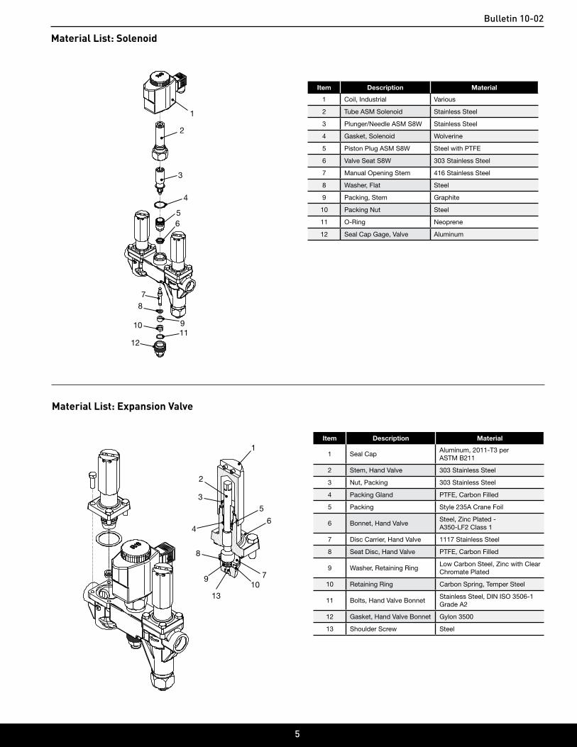
Material List: Solenoid
Item Description Material
1 Coil, Industrial Various
2 Tube ASM Solenoid Stainless Steel
3 Plunger/Needle ASM S8W Stainless Steel
4 Gasket, Solenoid Wolverine
5 Piston Plug ASM S8W Steel with PTFE
6 Valve Seat S8W 303 Stainless Steel
7 Manual Opening Stem 416 Stainless Steel
8 Washer, Flat Steel
9 Packing, Stem Graphite
10 Packing Nut Steel
11 O-Ring Neoprene
12 Seal Cap Gage, Valve Aluminum
Material List: Expansion Valve
Item Description Material
1 Seal CapAluminum, 2011-T3 per ASTM B211
2 Stem, Hand Valve 303 Stainless Steel
3 Nut, Packing 303 Stainless Steel
4 Packing Gland PTFE, Carbon Filled
5 Packing Style 235A Crane Foil
6 Bonnet, Hand ValveSteel, Zinc Plated - A350-LF2 Class 1
7 Disc Carrier, Hand Valve 1117 Stainless Steel
8 Seat Disc, Hand Valve PTFE, Carbon Filled
9 Washer, Retaining RingLow Carbon Steel, Zinc with Clear Chromate Plated
10 Retaining Ring Carbon Spring, Temper Steel
11 Bolts, Hand Valve BonnetStainless Steel, DIN ISO 3506-1 Grade A2
12 Gasket, Hand Valve Bonnet Gylon 3500
13 Shoulder Screw Steel
1
2
3
4
56
78
91011
12

Bulletin 10-02
6
Item Description
1 Model - Connection Size
2 Safe Working Pressure
3 Port Size
4 Maximum Operating Pressure Differential
5 Year / Serial Number
Nameplate Information
Table 2: S8VS Nameplate Identification
Figure 3: S8VS Nameplate
1
54
3
2
In the event the valve is left disassembled for any length of time, protecting the components is essential. Place the components in a polyethylene bag or apply a rust protection agent, such as refrigerant oil.
Contractors need to follow a WPS (Welding Procedure Specifcation) for all welding. The procedure must be qualifed and the welder doing the weld qualifed to perform that procedure.
The codes applicable to the welding of socket weld valves require that the pipe be inserted into the socket until bottomed against the stop. The pipe is then to be backed out approximately 1 ⁄16 of an inch before welding. Use of welding rings is optional, but recommended for butt weld valves. They help alignment, control gap for full penetration welding, and reduce welding debris entry.
Note: When welding carbon steel and stainless steel, the welded joint should be painted to prevent galvanic corrosion.
Socket welding, where allowed, is the preferred connection. This connection helps to reduce the amount of welding debris in the piping system.
Remove welding debris and any dirt from the pipes and valve body before reassembling the valve.
Before putting valves into service, all pipe connections, valve seats, bonnet seals, and stem seals should be tested for leaks at pressure levels called for in the appropriate codes.
InstallationAll valves are packed for a maximum protection. Unpack carefully. Check the carton to make sure all items are unpacked. Save the enclosed instruction for the installer and eventual user.
Do not remove the protective coverings from the inlet and outlet of the valve until the valve is ready to be installed. Protect the inside of the valve from dirt and chips before and during installation.
i Caution
All personnel working on valves must be qualifed to work on refrigeration systems. If there are any questions contact Parker Refrigerating Specialties before proceeding with the work.
The valve should be installed in a location where it is easily accessible for adjustment and maintenance. The location should be such that the valve can not be easily damaged by material handing equipment. When it is necessary to insulate the valve, the insulation should be installed to provide access for adjustment and maintenance. Do not insulate solenoid coils. Proper indicating gauges should be installed to be easily visible to the operating engineer for system checks and adjustment purposes.
The preferred mounting method for the S8VS series is in the upright horizontal position. The valve must be installed with the arrow pointing in the direction of flow for the valve to function properly. Prior to welding, protect the inside of the valve body from welding debris and dirt.
Bulletin 10-02
7
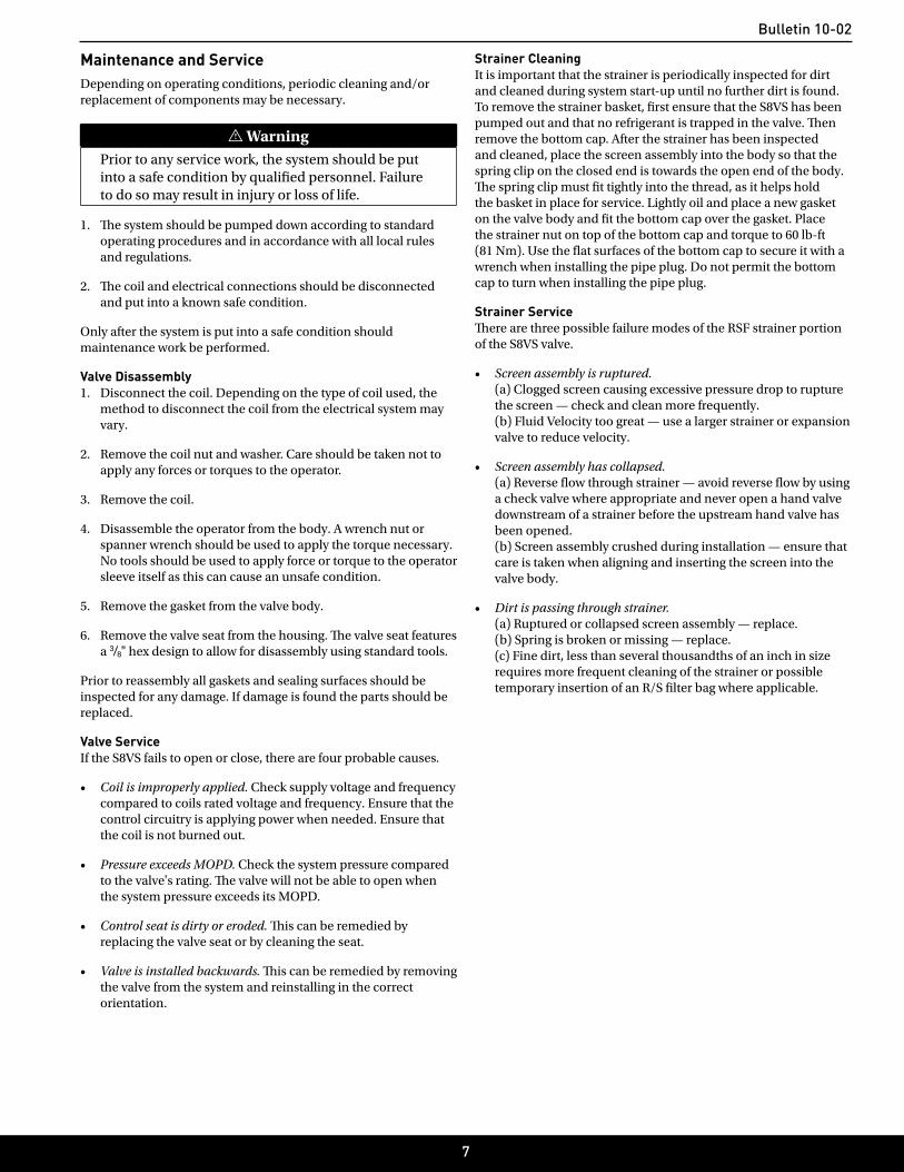
Maintenance and Service Depending on operating conditions, periodic cleaning and/or replacement of components may be necessary.
i WarningPrior to any service work, the system should be put into a safe condition by qualifed personnel. Failure to do so may result in injury or loss of life.
1. The system should be pumped down according to standard operating procedures and in accordance with all local rules and regulations.
2. The coil and electrical connections should be disconnected and put into a known safe condition.
Only after the system is put into a safe condition should maintenance work be performed.
Valve Disassembly1. Disconnect the coil. Depending on the type of coil used, the
method to disconnect the coil from the electrical system may vary.
2. Remove the coil nut and washer. Care should be taken not to apply any forces or torques to the operator.
3. Remove the coil.
4. Disassemble the operator from the body. A wrench nut or spanner wrench should be used to apply the torque necessary. No tools should be used to apply force or torque to the operator sleeve itself as this can cause an unsafe condition.
5. Remove the gasket from the valve body.
6. Remove the valve seat from the housing. The valve seat features a 3/8" hex design to allow for disassembly using standard tools.
Prior to reassembly all gaskets and sealing surfaces should be inspected for any damage. If damage is found the parts should be replaced.
Valve ServiceIf the S8VS fails to open or close, there are four probable causes.
• Coil is improperly applied. Check supply voltage and frequency compared to coils rated voltage and frequency. Ensure that the control circuitry is applying power when needed. Ensure that the coil is not burned out.
• Pressure exceeds MOPD. Check the system pressure compared to the valve's rating. The valve will not be able to open when the system pressure exceeds its MOPD.
• Control seat is dirty or eroded. This can be remedied by replacing the valve seat or by cleaning the seat.
• Valve is installed backwards. This can be remedied by removing the valve from the system and reinstalling in the correct orientation.
Strainer CleaningIt is important that the strainer is periodically inspected for dirt and cleaned during system start‑up until no further dirt is found. To remove the strainer basket, frst ensure that the S8VS has been pumped out and that no refrigerant is trapped in the valve. Then remove the bottom cap. After the strainer has been inspected and cleaned, place the screen assembly into the body so that the spring clip on the closed end is towards the open end of the body. The spring clip must ft tightly into the thread, as it helps hold the basket in place for service. Lightly oil and place a new gasket on the valve body and ft the bottom cap over the gasket. Place the strainer nut on top of the bottom cap and torque to 60 lb‑ft (81 Nm). Use the flat surfaces of the bottom cap to secure it with a wrench when installing the pipe plug. Do not permit the bottom cap to turn when installing the pipe plug.
Strainer ServiceThere are three possible failure modes of the RSF strainer portion of the S8VS valve.
• Screen assembly is ruptured. (a) Clogged screen causing excessive pressure drop to rupture the screen — check and clean more frequently. (b) Fluid Velocity too great — use a larger strainer or expansion valve to reduce velocity.
• Screen assembly has collapsed. (a) Reverse flow through strainer — avoid reverse flow by using a check valve where appropriate and never open a hand valve downstream of a strainer before the upstream hand valve has been opened. (b) Screen assembly crushed during installation — ensure that care is taken when aligning and inserting the screen into the valve body.
• Dirt is passing through strainer. (a) Ruptured or collapsed screen assembly — replace. (b) Spring is broken or missing — replace. (c) Fine dirt, less than several thousandths of an inch in size requires more frequent cleaning of the strainer or possible temporary insertion of an R/S flter bag where applicable.
Bulletin 10-02
8
146mm[5.76”]
56mm[2.22”]
164mm[6.46”]
117mm[4.62”]
235mm[9.25”]
Clearance Zone 152.40 [6.00]
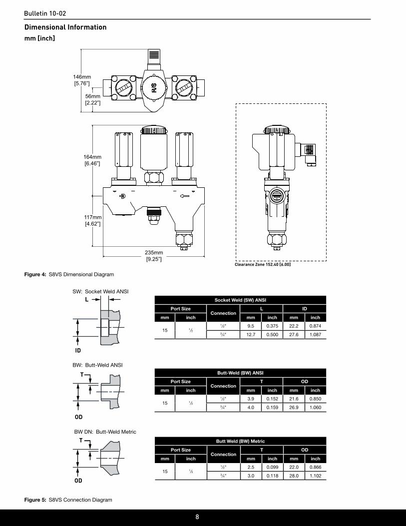
Dimensional Informationmm [inch]
Figure 4: S8VS Dimensional Diagram
L
ID
Socket Weld (SW) ANSI
Port SizeConnection
L ID
mm inch mm inch mm inch
15 1⁄21 ⁄2" 9.5 0.375 22.2 0.874
3 ⁄4" 12.7 0.500 27.6 1.087
SW: Socket Weld ANSI
OD
T Butt-Weld (BW) ANSI
Port SizeConnection
T OD
mm inch mm inch mm inch
15 1⁄21 ⁄2" 3.9 0.152 21.6 0.850
3 ⁄4" 4.0 0.159 26.9 1.060
BW: Butt-Weld ANSI
OD
T Butt Weld (BW) Metric
Port SizeConnection
T OD
mm inch mm inch mm inch
15 1⁄21 ⁄2" 2.5 0.099 22.0 0.866
3 ⁄4" 3.0 0.118 28.0 1.102
BW DN: Butt-Weld Metric
Figure 5: S8VS Connection Diagram

Bulletin 10-02
9
Parts Kit Reference
Figure 6: S8VS Exploded View
1 Encapsulated coils are available in a variety of styles and voltages. Contact factory for coil options and part number.
S8VS Service Parts List
Item Description Kit DescriptionKit/
Part No.
12
KnobO-Ring
Knob KitStandard (No LED)Green LEDRed LED
205237208543208544
1 - 23
Knob KitCoil
Industrial CoilConsult
Price List
46
Tube Assembly, SolenoidGasket, Solenoid
Tube KitStandardDN
209320209321
56
Plunger/Needle AssemblyGasket, Solenoid
Plunger KitAC CoilDC Coil
201019201021
678
Gasket, SolenoidPistonSeat
Piston/Seat Kit 210562
6 (10)Gasket, Solenoid Tube Assembly
Gasket Kit 209322
910
Seal CapGasket, Seal Cap
Seal Cap KitHand Shut OffHand ExpansionStop Check
210458210514210515
1112(4)
-
Bonnet Assembly, S8VSBolts, 5 ⁄16"-18 x 1" Long SSGasket, Bonnet
Bonnet Assembly KitHand Shut OffHand ExpansionStop Check
210564210565210567
1314151617
Strainer BasketGasket, StrainerCap, Bottom StrainerCoverPipe Plug
1/2" Screen Kit 205945
18192021
Stem, Manual OpeningFlat WasherPackingPacking Nut
Opening Stem Kit 210563
- (2)6
14
Gaskets, Bonnet AssemblyGasket, Solenoid Tube AssemblyGasket, Strainer
Gasket Kit, S8VS 210561
2223
O-Ring, CapCap, Manual Opening Stem
Cap, Manual Opening Stem
209916
Table 3: S8VS Repair Kits [1]
1
6
8
9
5
4
7
3
12(4)
11
19
2
10
16
15
20
13
14
21
17
22
9
10
12(4)
11
23
18

Bulletin 10-02
10
Bulletin 10-02
11
ISO 9001 CERTIFIED
Safe Operation (See Bulletin RSBCV)People doing any work on a refrigeration system must be qualified and completely familiar with the system and the Refrigerating Specialties Division valves involved, or all other precautions will be meaningless. This includes reading and understanding pertinent Refrigerating Specialties Division Product Bulletins and Safety Bulletin RSB prior to installation or servicing work.
Where cold refrigerant liquid lines are used, it is necessary that certain precautions be taken to avoid damage which could result from liquid expansion. Temperature increase in a piping section full of solid liquid will cause high pressure due to the expanding liquid which can possibly rupture a gasket, pipe or valve. All hand valves isolating such sections should be marked, warning against accidental closing, and must not be closed until the liquid is removed. Check valves must never be installed upstream of solenoid valves, or regulators with electric shut-off, nor should hand valves upstream of solenoid valves or downstream of check valves be closed until the liquid has been removed.
It is advisable to properly install relief devices in any section where liquid expansion could take place. Avoid all piping or control arrangements which might produce thermal or pressure shock.
For the protection of people and products, all refrigerant must be removed from the section to be worked on before a valve, strainer, or other device is opened or removed. Flanges with ODS connections are not suitable for ammonia service.
WarrantyAll Refrigerating Specialties products are under warranty against defects in workmanship and materials for a period of one year from date of shipment from factory. This warranty is in force only when products are properly installed, field assembled, maintained, and operated in use and service as specifically stated in Refrigerating Specialties Catalogs or Bulletins for normal refrigeration applications, unless otherwise approved in writing by the Refrigerating Specialties Division. Defective products, or parts thereof returned to the factory with transportation charges prepaid
and found to be defective by factory inspection, will be replaced or repaired at Refrigerating Specialties option, free of charge, F.O.B. factory. Warranty does not cover products which have been altered, or repaired in the field, damaged in transit, or have suffered accidents, misuse, or abuse. Products disabled by dirt or other foreign substances will not be considered defective.
The express warranty set forth above constitutes the only warranty applicable to Refrigerating Specialties products, and is in lieu of all other warranties, expressed or implied, written including any warranty of merchantability, or fitness for a particular purpose. In no event is Refrigerating Specialties responsible for any consequential damages of any nature whatsoever. No employee, agent, dealer or other person is authorized to give any warranties on behalf of Refrigerating Specialties, nor to assume, for Refrigerating Specialties, any other liability in connection with any of its products.
© 2018 Parker Hannifin Corporation 314449RSD ECO: 0209946 03/07/2018