Embed Size (px)
Citation preview

17
SimAUD�2014� Symposium�on�Simulation�for�Architecture�and�Urban�Design Tampa,�Florida,�USA
Parametric Spatial Models for Energy Analysis in the Early Design Stages
Wassim Jabi
Welsh School of Architecture Cardiff University
Cardiff, United Kingdom, CF10 3NB [email protected]
Keywords: Spatial Models, Energy Analysis, Parametric Design, Thermal Simulation, Non-manifold Geometry.
Abstract Much of the research into integrating performance
analysis in the design process has focused on the use of Building Information Modeling (BIM) as input for analysis engines. The main disadvantage of this approach is that BIM models are resource intensive and thus are usually developed in the later stages of design. BIM models are also not necessarily compatible with energy analysis engines and thus a conversion and export process is needed. This can lead to data loss, calculation errors, and failures.
Starting with the premise that energy analysis is more compatible with earlier design stages where simpler schematic models are the norm, this paper presents a software system that integrates non-manifold spatial topology, a parametric design environment and an energy analysis engine for a more seamless generate-test cycle in the early design stages. The paper includes a description of the system architecture, initial results, and an outline of future work.
1. INTRODUCTIONThe noted architect Steven Holl has written, “While
artists work from the real to the abstract, architects must work from the abstract to the real” (Holl 2013). Underpinning this quote is the notion that architects invariably begin their design process with representations that are not merely simpler models of what they would construct in later stages, but ones that are abstracted to encompass only the ideas, concepts, and information necessary to move the design process forward. As the design process unfolds, architects create models that more closely correspond to the real project. They also then start to
analyse the implications of their design decisions and simulate performance aspects of their project. Unfortunately, most of these analyses happen later in the design process when design modification may not be feasible or be very costly. In many cases, the analysis (e.g., thermal and daylight analysis) is conducted to measure compliance with external regulations or to satisfy the client regarding the performance of the project rather than to fundamentally reflect on the parameters of the design (Mhadavi et al. 2003). Many researchers, architects, and clients wish to have that analysis done earlier in the design process so that they discover and avoid problems earlier and create a more considered design solution (Brahme et al. 2001). Unsurprisingly, the difficulty with conducting performance analysis in the early design stage stems mainly from the lack of appropriate representations and information. Current performance analysis software such as daylighting requires detailed inputs of materials and constructions that are simply not available during the early design stages.
While architects create several types of analogue and digital representations and conduct several types of analyses, the focus in this paper is on spatial digital representations and models of their work and the role of energy analysis in the early stages of design. The aim of this research project is to more closely harmonise the outputs of parametric digital spatial representations with the input requirements for building performance simulation. The goal is to better integrate energy analysis in the design process and thus improve the overall outcome of design.
DSOS is software that was developed by the author to analyse the energy use of a parametrically designed building using Autodesk DesignScript and the U.S. Department of Energy (DOE) EnergyPlus software through the use of the

18
SimAUD�2014� Symposium�on�Simulation�for�Architecture�and�Urban�Design Tampa,�Florida,�USA
OpenStudio Software Development Kit (SDK). EnergyPlus
is a whole building energy simulation program that allows
building professionals and researchers to better understand
the performance of the simulated building and optimise its
design to use less energy and resources (Crawley et al.
2000). It was chosen over other tools such as ECOTECT
due to the fact that it is an industry standard and offers a
robust API that is easy to work with. Additionally,
EnergyPlus is being incorporated in cloud-based solutions
that promise to vastly increase processing speed. However,
additional analysis engines should be considered in the
future. OpenStudio is a collection of software tools
developed by the U.S. National Renewable Energy
Laboratory (NREL) to support whole building energy
modelling using EnergyPlus and advanced daylight analysis
using Radiance (Guglielmetti et al. 2011). OpenStudio is an
open source project to facilitate community development,
extension, and private sector adoption. OpenStudio includes
graphical interfaces along with an SDK. The DSOS plugin
exposes many of these services in scripts, handling most of
the process of sorting, labelling, and otherwise abstracting a
model into OpenStudio’s specifications. To generate an
analysis, a scriptwriter simply needs to specify the
building’s location through a weather file, specify which
days and conditions to simulate, its general program
(architectural use), and a spatial representation of the form.
Once the simulation is complete, the results are displayed in
the parametric design environment. This workflow allows
the users to iterate parametrically through multiple design
alternatives and even display a matrix of alternatives side-
by-side for comparative analysis without the need to export
to different software packages and use file formats that may
lose information in the process.
2. MODELS FOR ENERGY SIMULATION While daylight simulations are most accurate when
models closely represent reality in detail and material (Ibara
and Reinhold 2009), energy analysis software such as
EnergyPlus requires input models to consist of
infinitesimally thin surfaces that represent walls or partitions
between thermal zones. This has presented a problem for the
simulation of models built within Building Information
Modeling (BIM) environments. BIM models strive to
include all details needed to construct and manage a
building (Figure 1). Yet, energy simulation requires a
simplified and abstracted version of that model. As
Jackubiec and Reinhart report, this has divided the building
simulation community because while BIM strives for a
single model, there are advantages of using hybrid models
that combine several models for several types of analyses
(Jackubeic and Reinhart 2011).
Figure 1. A typical mature BIM model from industry.
Interestingly, architects and designers generally use
these types of ‘sketch models’ in the early stages of design
(Granadeiro 2012). Architects frequently think of their
design projects to be made out of spaces that are enclosed
by boundaries that have yet to acquire thickness and
materiality (Figure 2). They place these spaces intuitively
and visually in proportion to each other without much
attention to tectonic detail (Jabi 1998). This conceptual or
idealised approach allows designers to “build the lightest
possible model using the least effort that gives the most
accurate feedback about their design …” (Aish and Pratap
2013).
Figure 2. A typical architect’s sketch from the early design stages. Image
courtesy of fc3 architecture+design.
If architects and designers sketch and build idealised
analogue spatial models that can be a good fit with energy
simulation, the question then becomes: do they do the same
when building digital models? Sadly, in most cases the
answer is no. One example is the use of SketchUp as a
generator of models for energy analysis. SketchUp is one of
19
SimAUD�2014� Symposium�on�Simulation�for�Architecture�and�Urban�Design Tampa,�Florida,�USA
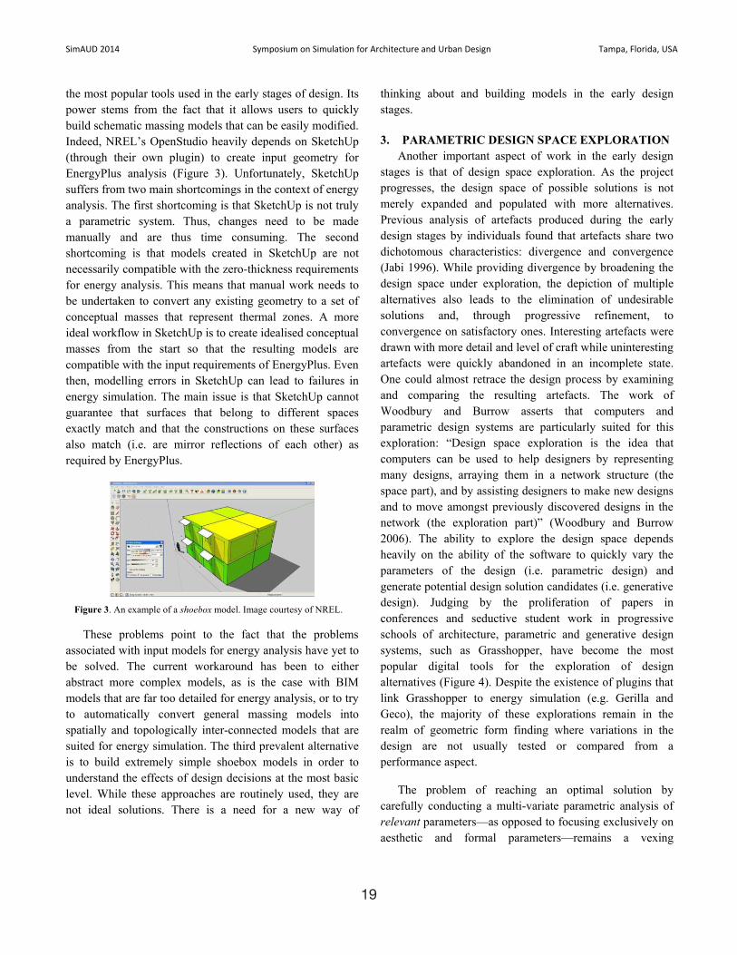
the most popular tools used in the early stages of design. Its power stems from the fact that it allows users to quickly build schematic massing models that can be easily modified. Indeed, NREL’s OpenStudio heavily depends on SketchUp (through their own plugin) to create input geometry for EnergyPlus analysis (Figure 3). Unfortunately, SketchUp suffers from two main shortcomings in the context of energy analysis. The first shortcoming is that SketchUp is not truly a parametric system. Thus, changes need to be made manually and are thus time consuming. The second shortcoming is that models created in SketchUp are not necessarily compatible with the zero-thickness requirements for energy analysis. This means that manual work needs to be undertaken to convert any existing geometry to a set of conceptual masses that represent thermal zones. A more ideal workflow in SketchUp is to create idealised conceptual masses from the start so that the resulting models are compatible with the input requirements of EnergyPlus. Even then, modelling errors in SketchUp can lead to failures in energy simulation. The main issue is that SketchUp cannot guarantee that surfaces that belong to different spaces exactly match and that the constructions on these surfaces also match (i.e. are mirror reflections of each other) as required by EnergyPlus.
Figure 3. An example of a shoebox model. Image courtesy of NREL.
These problems point to the fact that the problems associated with input models for energy analysis have yet to be solved. The current workaround has been to either abstract more complex models, as is the case with BIM models that are far too detailed for energy analysis, or to try to automatically convert general massing models into spatially and topologically inter-connected models that are suited for energy simulation. The third prevalent alternative is to build extremely simple shoebox models in order to understand the effects of design decisions at the most basic level. While these approaches are routinely used, they are not ideal solutions. There is a need for a new way of
thinking about and building models in the early design stages.
3. PARAMETRIC DESIGN SPACE EXPLORATION Another important aspect of work in the early design
stages is that of design space exploration. As the project progresses, the design space of possible solutions is not merely expanded and populated with more alternatives. Previous analysis of artefacts produced during the early design stages by individuals found that artefacts share two dichotomous characteristics: divergence and convergence (Jabi 1996). While providing divergence by broadening the design space under exploration, the depiction of multiple alternatives also leads to the elimination of undesirable solutions and, through progressive refinement, to convergence on satisfactory ones. Interesting artefacts were drawn with more detail and level of craft while uninteresting artefacts were quickly abandoned in an incomplete state. One could almost retrace the design process by examining and comparing the resulting artefacts. The work of Woodbury and Burrow asserts that computers and parametric design systems are particularly suited for this exploration: “Design space exploration is the idea that computers can be used to help designers by representing many designs, arraying them in a network structure (the space part), and by assisting designers to make new designs and to move amongst previously discovered designs in the network (the exploration part)” (Woodbury and Burrow 2006). The ability to explore the design space depends heavily on the ability of the software to quickly vary the parameters of the design (i.e. parametric design) and generate potential design solution candidates (i.e. generative design). Judging by the proliferation of papers in conferences and seductive student work in progressive schools of architecture, parametric and generative design systems, such as Grasshopper, have become the most popular digital tools for the exploration of design alternatives (Figure 4). Despite the existence of plugins that link Grasshopper to energy simulation (e.g. Gerilla and Geco), the majority of these explorations remain in the realm of geometric form finding where variations in the design are not usually tested or compared from a performance aspect.
The problem of reaching an optimal solution by carefully conducting a multi-variate parametric analysis of relevant parameters—as opposed to focusing exclusively on aesthetic and formal parameters—remains a vexing

20
SimAUD�2014� Symposium�on�Simulation�for�Architecture�and�Urban�Design Tampa,�Florida,�USA
problem. Some researchers have made progress by using evolutionary heuristic methods to quickly evolve and search the solution space for a set of potentially optimal candidates (Figure 5). For example, Gerber and Lin have researched and integrated computational strategy using genetic algorithms to “expand the solution space of a design problem as well as presort and qualify candidate designs.” Their approach avoids the pitfall of attempting to find the perfect solution: “… What is not afforded nor necessarily expected is the solving for a single optimal result … the experiment is still inclusive of designer-driven choice, where the [chosen alternatives] exhibit some improved scoring, they are not necessarily the aggregate best scores as form and implicit architectural constraints come into play and become major factors for consideration in the design decision making.”
Figure 4. A typical exploration of architectural form using Grasshopper. Image courtesy of Rodrigo Ruiz.
Figure 5. Multi-variate parametric design space exploration. Image courtesy of Dr. David Gerber, USC School of Architecture.
Combining rapid design alternative generation with evolutionary heuristic methods can enable complex geometries to be better understood beyond their aesthetics and significantly strengthen the relationship between geometry and performance (Gerber and Lin 2012).
4. INTEGRATING NON-MANIFOLD TOPOLOGY, PARAMETRIC DESIGN AND ENERGY ANALYSIS
As stated earlier, the aim of this research is to integrate parametric systems and performance analysis engines. We envisage a seamless generate-test cycle that will ultimately be conducted in real-time and is invisible to the user (Figure 6). Such a cycle would avoid the drawbacks of file import and export and data loss due to subtle incompatibilities. This research project seeks to find out spatial representations and parametric digital workflows that are suitable for early design stages as well as energy simulation. The research starts with two premises based on the work of (Aish and Pratap 2013). The first premise is that a non-manifold topology, as explained below, satisfies the requirement for conceptual design as well as energy analysis. The second premise is that integrating a generative/parametric scripting environment with an energy simulation engine can help the designer make better decisions in the early design stages.
Figure 6. The design-analyse cycle.
4.1. Manifold and Non-Manifold Topology While it is beyond the scope of this paper to delve into
the mathematics of manifold topology, for the purposes of this paper one can think of three-dimensional manifold geometries with boundaries to be polyhedral solids such as cuboids. In manifold polyhedral geometries, each surface separates the interior solid condition of the object from the exterior world. Each edge is shared by exactly two surfaces of the solid. All surfaces form the outer boundary of the solid such that it is said to be watertight. These guaranteed attributes allow 3D software to easily operate on such geometry (e.g. calculating surface area, volume and

21
SimAUD�2014� Symposium�on�Simulation�for�Architecture�and�Urban�Design Tampa,�Florida,�USA
centroid, and intersecting the solid with other solids). Non-manifold geometry is also made of surfaces, edges, and vertices. However, edges can be shared by more than two surfaces (Figure 7). Furthermore, surfaces can either be a boundary between the solid interior of the object and the exterior world or between two spatial cells within the object. The implementation of non-manifold topology within DesignScript allows the scriptwriter to create regular polyhedral geometries at the start and then boolean them with other geometries using a non-regular (i.e. non-manifold) operation that maintains the interior surfaces that would have been otherwise lost (Aish and Pratap 2013). The implementation also allows the scriptwriter to slice a manifold geometry using a series of planes in order to create a non-manifold geometry with cells and surfaces. The scriptwriter can then query the non-manifold geometry for its vertices, its edges, its surfaces, and its cells. Methods within the non-manifold class return useful information, such as the cells at each side of a surface or whether the surface is a boundary between the inside and the outside of the object.
Figure 7. (Left) A manifold polyhedral geometry; (Right) a non-mainfold geometry.
4.2. The DSOS System Architecture The DSOS software architecture is composed of a
dynamically linked library (.dll) written in C# and a set of scripts using DesignScript which in turn runs as a plugin within the AutoCAD environment (Figure 8). In order to use the DSOS plugin, one must first install AutoCAD, the DesignScript software, EnergyPlus, and the DSOS files. DSOS provides the needed OpenStudio .dll files. The DSOS plugin generates files that are fully compatible with OpenStudio and EnergyPlus. Thus, a user can optionally install the OpenStudio graphical user interface software to further investigate the generated models or use other software that can read EnergyPlus file formats.
The DSOS system architecture is composed of the following files and parameters:
1) dsos.dll. This is a dynamically linked library thatprovides the dsos.Utility object. This objectprovides the main functionality (methods andattributes) for specifying an OpenStudio model. Forexample, the dsos.Utility object can create the mainabstract model, the building, the building storeys,the spaces and thermal zones, and save the model inpreparation for EnergyPlus analysis.
2) DSProtoGeometry.dll. This is a special version ofthe DesignScript ProtoGeometry library. In order toavoid naming conflicts with OpenStudio, thislibrary prefixes all DesignScript geometries with theletters “DS” (e.g. DSCuboid instead of Cuboid).This is a temporary workaround. Autodesk isworking to resolve this issue so that DSOSscriptwriters can revert to using the regularProtoGeometry.dll file.
3) OpenStudio.dll. This is the NREL OpenStudio suiteof linked libraries.
4) EPW file. This is the standard EnergyPlus Weatherdata file. This file describes the weather data for aspecific geographic location.
5) DDY file. This is the ASHRAE Design ConditionsDesign Day Data file. These files specify the designdays and their conditions that EnergyPlus uses torun its simulation.
6) OSM file. This is the NREL OpenStudio TemplateFile. This file provides a minimal template for aparticular building type. NREL provides severaltemplates. A template usually contains defaultconstruction sets and schedule sets, but nogeometry.
7) Initialise.ds. This script imports the required classesfor DSOS to function properly. It initialises certainparameters with default values that can be changedby the user.
8) Building.ds. This script can be named by the userand is where the user constructs a parametricbuilding using a non-manifold topology.

22
SimAUD�2014� Symposium�on�Simulation�for�Architecture�and�Urban�Design Tampa,�Florida,�USA
9) Analyse.ds. This script loads the building from the previous scripts, conducts the analysis and displays the results.
10) Building.osm. This is the OpenStudio model generated by the DSOS software. It serves as the input to the analysis cycle.
11) eplusout.sql. This is the standard SQL database file generated by EnergyPlus. This file gets read back into the software and can be queried using the standard SQL format.
Figure 8. The DSOS system architecture.
4.3. The DSOS Workflow The DSOS Workflow is quite simple. The user
structures their design scripts by modifying default scripts organised in three stages (e.g. Initialise.ds, Building.ds,Analyse.ds). The initialisation script usually remains as is with only a change to some path names depending on the installation. The second file is where the user can generate any parametric non-manifold geometry they wish. This geometry can be derived from the parametric process at any time. The only three requirements for that script are: 1) Define a global variable called building to store the resulting non-manifold geometry of the building. 2) Define a global variable called numFloors with a value greater than 1 that represents the number of floors (stories) in the
building. 3) Define a global variable called glazingRatiothat represents the ratio of glazing to exterior wall surfaces.
Within the analysis script a user can request that the analysis is conducted and then construct an SQL query to retrieve any results from the EnergyPlus analysis. These results can then be visually displayed to the user or used to further investigate and modify the design.
The usual steps to build a parametric model and visualise analysis results consist of the following steps:
1) Import the Initialise.ds file:
import("C:\dsos\Scripts\Initialise.ds");
2) Define the required parameters for the building. The script assumes the dimensions of the building are in metres and the temperatures in degrees Celsius. The glazing ratio applies to each exterior wall surface individually.
buildingWidth = 40; buildingLength = 30; buildingHeight = 15; numFloors = 5; glazingRatio = 0.5;
3) Generate a non-manifold geometry (to be called building). Each cell in the non-manifold geometry translates into a space in the OpenStudio model and has its own thermal zone. Each horizontal slice of the geometry will translate into an OpenStudio Building Storey.
4) Create an Analyse.ds script (starting from the given default file) that imports the previous script:
import("C:\dsos\Scripts\MyBuilding.ds");
5) Get the OpenStudio Model from the template:
osModel = dsos.getModelFromTemplate(templatePath, EPWPath, DDYPath);
6) Get the OpenStudio Building from the osModel:
osBuilding = dsos.getBuilding(osModel, buildingName, buildingType, buildingHeight, numFloors, spaceType);
7) Create a space for each cell in the non-manifold geometry:
numCells = Count(building.Cells); list = 1..numCells; names = "Space_" + list; spaces = addSpace(building.Cells, names, osModel, WCS.ZAxis);

23
SimAUD�2014� Symposium�on�Simulation�for�Architecture�and�Urban�Design Tampa,�Florida,�USA
8) Save the model and run the analysis:
saveCondition = dsos.saveModel(osModel, outputPath); result = getAnalysisResults(logPath, outputPath, EPWPath, outDirPath); totalSE = result.totalSiteEnergy(); Print("Total Site Energy use: "+totalSE.get());
The scriptwriter can then experiment with retrieving and
displaying different energy simulation results. Further
information regarding NREL’s sqlFile object specification
can be found at: http://goo.gl/jfnKtq
5. INITIAL RESULTSThis paper reports on initial results from test runs of the
software where some analysis results such as peak
temperatures for cooling loads were translated into colours
and assigned to the respective spaces in the model (Figure
9).
Figure 9. The DSOS graphical user interface.
The resulting geometry is overlaid with the original
parametric model. These results should not be considered
indicative of the full extent of the capabilities of the
software. For example, the parametric software can create
geometry of any degree of complexity and is not limited to
orthogonal structures (Figure 10). Multiple parametric
studies can also be conducted and presented to the user in a
matrix, or browsed through. The results indicate that using
non-manifold topology is a powerful representation of both
parametric spatial constructs and input models for energy
analysis. The tight integration of parametric design system
and an energy analysis engine created a reasonably seamless
experience and, more importantly, avoided the pitfalls of
file export and import. By being mostly script-based, DSOS
can be considered an open platform for scriptwriters to
develop their own spatial parametric constructs and analysis
scenarios.
Figure 10. Parametric modeling and analysis of non-orthogonal building.
6. FUTURE WORKThe DSOS software is under active development. One of
the main obstacles to overcome is the amount of time it
takes EnergyPlus to complete its analysis. A possible
solution is to integrate distributed high performance
computing (HPC) with DSOS. We are pursuing that
solution with our university’s HPC centre as well as
investigating NREL’s new initiative to offer OpenStudio as
server software on Amazon’s Elastic Compute Cloud (EC2).
In doing so, we will thrive to maintain a seamless generate-
test cycle. Another option would be to use HPC to generate
a vast array of possible candidates, similar to (Gerber and
Lin 2012), and invent user-friendly ways to visualise,
explore and select optimal pre-analysed solutions. The
current implementation of non-manifold topology in
DesignScript does not allow for the specification of sub-
surfaces (e.g., glazing subsurfaces). In DSOS, we opted to
use a glazing ratio as a temporary substitute for a more
accurate representation of glazing surfaces. While it is not
impossible to add the ability to model glazing surfaces in
DSOS itself, it would be preferable if the non-manifold
topology itself were extended to handle subsurfaces. Finally,
we intend to offer DSOS on as many platforms as possible.
To that end, we are currently developing a version that will
run within Autodesk’s 3ds Max since it too can create and
represent non-manifold geometries. We are also planning
support for Autodesk’s Vasari and Revit if and when
Autodesk incorporates non-manifold geometry into
DesignScript and/or Dynamo for these platforms. Finally,
we are keenly interested in verifying the software against
industry standard case studies to find out if energy analysis
in the early design stages using idealised spatial models is

24
SimAUD�2014� Symposium�on�Simulation�for�Architecture�and�Urban�Design Tampa,�Florida,�USA
comparable in accuracy to analysis conducted using more complex and mature BIM models. The comparison to real world case studies is always of interest, but we are cognisant that even the most sophisticated energy analysis results are far from their real-world values. Because this software is intended for the early stages of design, we are less interested in exact measures and more interested in trend analysis based on parametric variation.
7. CONCLUSION This paper provided an alternative approach to the
integration of energy analysis in the design process. Rather than rely on file export and import of BIM models and their associated pitfalls, energy analysis can be conducted much earlier in the design cycle using far simpler and more idealised models. We presented the DSOS software that integrated the use of non-manifold topology, a parametric design system, and an energy analysis engine for use in the early design stages. The results of this software can be visualised using user-friendly methods to investigate trends rather than focus on precise values. We believe this is an appropriate approach for designers and architects in the early design stages where complete building information is not available and precise numeric information is not needed. Since analysis data is present in the software as it is running, it can be both visualised and used to affect the parameters of the design. Although DSOS is in its initial development stages, initial results indicate that energy analysis in the early design stages is possible and can raise awareness of the energy implications of early design decisions.
Acknowledgements This research would not have been possible without the
contribution of Dr. Robert Aish, who suggested I research non-manifold geometries and helped me develop my ideas. I am also grateful for the invaluable help of Daniel Macumber and the whole OpenStudio team at NREL. I would also like to thank Prof. Ian Knight, Simon Lannon, and Enrico Crobu at the Welsh School of Architecture for their insights and help in developing the ideas behind this paper.
References AISH, R. AND PRATAP, A. 2013. Spatial Information Modeling of Buildings
Using Non-Manifold Topology with ASM and DesignScript. Advances in Architectural Geometry 2012. 25-36.
BRAHME, R. ET AL. 2003. Complex Building Performance Analysis in Early Stages of Design. Seventh International IBPSA Conference, Rio de Janeiro, Brazil, August 13-15, 2001. 661-668.
CRAWLEY, D. ET AL. 2000. EnergyPlus: Energy Simulation Program. ASHRAE Journal Online. Vol. 42, No. 4, April 2000. 49-56.
GERBER, D., LIN, S. 2012. Synthesizing Design Performance: An evolutionary approach to multidisciplinary design search. 32nd Annual Conference of the Association for Computer Aided Design in Architecture (ACADIA), San Francisco 18-21 October 2012. 67-75.
GRANADEIRO, V., ET AL. 2013. Building Envelope Shape Design in Early Stages of the Design Process: Integrating architectural design systems and energy simulation. Automation in Construction 32 (2013). 196–209.
GUGLIELMETTI, R., MACUMBER, D. AND LONG, N. 2011. OpenStudio: An Open Source Integrated Analysis Platform. Twelfth International IBPSA Conference, Sydney, Australia, November 14-16, 2011. 442-449.
HOLL, S. 2013. What is Architecture? (Art?). The Brooklyn Rail: Critical Perspectives on Arts, Politics, and Culture. September 2013. Available at: http://www.brooklynrail.org/2013/09/criticspage/what-is-architecture-art. (Accessed on 8 November 2013).
IBARRA, D. AND REINHART, C. 2009. Daylight Factor Simulations – How Close Do Simulation Beginners ‘Really’ Get?. Eleventh International IBPSA Conference, Glasgow, Scotland, July 27-30, 2009. 196-203.
JABI, W. 1996. An Outline of the Requirements for a Computer-Supported Collaborative Design System. Open House International 21/1 (March 1996). 22-30.
JABI, W. 1998. The Role of Artifacts in Collaborative Design. Proceedings of the Third Conference on Computer-Aided Architectural Design Research in Asia, Osaka, Japan: CAADRIA, Department of Architecture and Civil Engineering, Kumamoto University, 1998. 271-280.
JACKUBEIC, J.A. AND REINHART, C. 2011. Diva 2.0: Integrating Daylight And Thermal Simulations Using Rhinoceros 3d, Daysim And EnergyPlus. Twelfth International IBPSA Conference, Sydney, Australia, November 14-16, 2011. 2202-2209.
MAHDAVI, A. ET AL. 2003. An Inquiry into The Building Performance Simulation Tools Usage By Architects in Austria. Eighth International IBPSA Conference, Eindhoven, Netherlands, August 11-14, 2003. 777-784.
NAGHMI I.S. ET AL. 2011. Design Space Exploration in Parametric Systems: Analyzing effects of goal specificity and method specificity on design solutions. ACM Creativity & Cognition, Atlanta, Georgia, November 3-6, 2011. 249-258.
WOODBURY, R. AND BURROW, A. 2006. Whither Design Space? AIE EDAM: Artificial Intelligence for Engineering Design, Analysis, and Manufacturing, Vol. 20, No. 02, May 2006. 63-82.