Embed Size (px)
Citation preview

IJISET - International Journal of Innovative Science, Engineering & Technology, Vol. 4 Issue 6, June 2017
ISSN (Online) 2348 – 7968 | Impact Factor (2016) – 5.264
www.ijiset.com
162
Parametric Analysis of Gas Turbine Cogeneration cycle
for Various Blade Cooling Means
Ankita Sharma P
1P, Shubham TiwariP
2P, Laxmi Kant SahuP
3
P
1PDepartment of Mechanical Engineering, Technocrats Institute of Technology, Bhopal, MP, India;
P
2PDepartment of Mechanical Engineering, Technocrats Institute of Technology, Bhopal, MP, India,
P
3PDepartment of Mechanical Engineering, Institute of Technology, Korba, CG, India;
Abstract
The present work deals with the first law
thermodynamic analysis of cogeneration cycle
employing different means of turbine blade
cooling for various configurations. Based on
modeling and governing equations a computer
program has been constructed in C++ language,
to do the first law thermodynamic analysis of
eight configurations of cogeneration cycle.
With the help of input data, results have been
plotted and analyzed in terms of dependent and
independent parameters.
Key words: Air film cooling, heat recovery
steam generator (HRSG). Turbine inlet
temperature (TIT), Specific fuel consumption
(SFC)
1. Introduction
Energy is one of the major inputs for the
economic development of any country and is
vital to the sustenance of a modern economy.
In the case of the developing countries, the
energy sector assumes a critical importance in
view of the ever increasing energy needs
requiring huge investments to meet them. Co-
generation refers to the simultaneous
generation of power and heat. Thermal power
plants in general, do not convert all of their
available energy into electricity. In most power
plants, a bit more than half is wasted as excess
heat. By capturing the excess heat in the form
of steam generated from the exhaust of gas
turbine in heat recovery steam generator, Co-
generation plants uses heat that would be
wasted in a conventional power plant,
potentially reaching an efficiency of up to
89%, compared with 55% for the best
conventional plants. This means that less fuel
needs to be consumed to produce the same
amount of useful energy. The system is
efficient and the cost of power production per
kW is less. Also, less pollution is produced for
a given economic benefit. A large number of
configurations of cogeneration cycle plants are
possible. Schematic and energy flow diagram
of cogeneration cycle plant is represented in
figure 1.1.

IJISET - International Journal of Innovative Science, Engineering & Technology, Vol. 4 Issue 6, June 2017
ISSN (Online) 2348 – 7968 | Impact Factor (2016) – 5.264
www.ijiset.com
163
Figure 1.1(a) Schematic diagram of a cogeneration cycle plant (b) Energy flow diagram of cogeneration cycle power plant
Various researchers have contributed a lot in
the field of Gas turbine, cogeneration plant and
cooling means of the turbine. Shukla and Singh
[1] investigated the combined effect of inlet
evaporative cooling (IEC), steam injection (SI)
and film cooling (FC) on the power
augmentation of simple gas turbine cycle.
Ahmed et al. [2] presents a proposal of a
combined scheme for applying a vapour
compression refrigeration system to cool the
condenser of a steam plant. In this scheme the
refrigerant (mostly liquid) leaving the throttle
valve of the refrigeration system is circulated
through the pipes of the shell and tube
condenser, while the steam exhausting the plant
turbine flows in the shell around the outer
surfaces of the tubes. Mohamed et al. [3]
experienced about the ambient temperatures
rising during hot seasons have significant
losses and impacts on both output power and
efficiency of the gas turbine. When the ambient
temperature increases, the air mass flow rate
decreases, and hence leads to reduce the gas
turbine produced power. Ambient air can be
cooled by using either evaporative cooler or
absorption chiller. Sanjay et al. [4] compared
the thermodynamic performance of MS9001
gas turbine based cogeneration cycle having a
two-pressure heat recovery steam generator
(HRSG) for different blade cooling means.
Dong et al. [5] have used the Conjugate
calculation methodology to simulate the C3X
gas turbine vanes cooled with leading edge films
of “shower-head” type. Ting W. and Xianchang
Li [6] successfully used Air film cooling to
cool gas turbine hot sections for the last half
century. A promising technology is proposed to
enhance air film cooling with water mist
injection. They obtained the adiabatic wall film
cooling effectiveness and the heat transfer over
a film -cooled surface that is made inclined at
various angles with respect to a highly
turbulent flow. Zhihong G. et al. [7] have
measured the film cooling effectiveness on the
surface of a high pressure turbine blade using
the pressure sensitive paint (PSP) technique.
Four rows of axial laid-back, fan-shaped
cooling holes are distributed on the pressure
side while two such rows are provided on the
suction side. Krishnan V. et al [8] established
an analytical study of low temperature hot
corrosion (LTHC) in the context of high
temperature turbines using coal gas or syngas
with trace amount of sulphur in the fuel. Sanjay
et al [9] have presented a comparative study of
the influence of different means of turbine

IJISET - International Journal of Innovative Science, Engineering & Technology, Vol. 4 Issue 6, June 2017
ISSN (Online) 2348 – 7968 | Impact Factor (2016) – 5.264
www.ijiset.com
164
blade cooling on the thermodynamic
performance of combined cycle power plant.
Seven schemes involving air and steam as
coolants under open and closed loop cooling
techniques have been studied. Sanjay et al. [10]
have presented parametric energy and exergy
analysis of reheat gas–steam combined cycle
using closed-loop-steam-cooling. Of the blade
cooling techniques closed-loop-steam-cooling
has been found to be superior to air-film
cooling. The literature review on cogeneration
cycle based power plants exhibits that an
extensive research is needed in this direction to
enhance the performance of these power plants.
The present work deals with analysis of
cogeneration cycles employing different means
of turbine blade cooling for various
configurations.
The Paper is organized as following the
introduction, Section 2 describe the modelling
of various configurations of cogeneration cycle
plants by governing equations. Section 3
illustrates the results obtained from modelling
of the various design parameters and also the
results are analyzed and discussed. Finally
conclusions are drawn in Section 4.
2. Mathematical modeling of cooling
blades of gas turbine
Unlike steam turbine blading, gas turbine
blading need cooling. The objective of the
blade cooling is to keep the metal temperature
at the safe level, to ensure, a long creep life,
low oxidation rates, and low thermal stresses.
The universal method of blade cooling is by air
bled from compressor or by other cooling fluid
flowing through the internal pressure in the
blades. The cooling techniques may be internal
convection, film or transpiration cooling. The
cooling medium may be air or steam. The
cooling loop may be open or closed. Thus
cooling means for gas turbine blading may be
categorized mainly in two categories. Open
loop cooling is further subdivided as Air
internal convection cooling (AICC), Air film
cooling (AFC), Air transpiration cooling
(ATC), Steam internal convection cooling
(SICC), Steam film cooling (SFC), Steam
transpiration cooling (STC). Open and closed
loop cooling of gas turbine is shown in Figure
2.1. In open loop cooling, the cooling fluid
mixes with the working fluid (i.e. the
combustion products), while in closed loop, the
cooling fluid does not mix with working fluid.
The different cooling techniques will require
different amounts of coolant flows.
Figure 2.1 Air cooled gas turbine with open &
closed loop blade cooling

IJISET - International Journal of Innovative Science, Engineering & Technology, Vol. 4 Issue 6, June 2017
ISSN (Online) 2348 – 7968 | Impact Factor (2016) – 5.264
www.ijiset.com
165
Sources of losses in open loop cooling are
much more than that is in closed loop
cooling. In open loop cooling, the mixing
of the spent cooling fluid with the main gas
stream causes total pressure loss and
reduction in gas enthalpy. There is a loss in
turbine output due to reduction of mass
flow rate of gas entering to the turbine due
to bled air from compressor. Further, there
is a cooling loss, which results in lower gas
turbine exhaust temperature and also
pumping loss, while closed loop cooling
only suffers from cooling loss and there is
no pressure loss due to mixing of two
streams.
In the present study open loop air
cooling techniques are used as cooling
medium. Several approaches for the
determination of open loop coolant flow
are given in the literature such as Louis et
al [11], Harlock et al. [12], El-Masri [13],
etc. the model used for cooled turbine is
the refined version of Louis et al. [11]
model and Harlock at al. [12] depicted in
Figures 2.2, 2.3, 2.4. The following
assumptions are made for the development
of model:
I. Gas turbine blades cooled by internal
convection are treated as heat exchangers
operating at constant temperature and the
coolant exit temperature is expressed as a
function of heat exchanger effectiveness.
II. A concept of isothermal effectiveness
�ηiso� is introduced for film or
transpiration cooling to account the
reduced heat transfer rate from hot gas to
blades. The isothermal effectiveness due to
transpiration cooling �ηiso, trans� is higher
than that due to film cooling. For internal
convection cooling ηiso = 0.
III. A factor, Fsa= 1.05 is used to
convert pitch line blade surface area to
actual blade surface area.
Open loop cooling:
(i) Internal Convection Cooling,
(ICC): A simple model for internal
convection cooling of blades is shown in
Figure 2.2. For an internally cooled turbine
configuration, the ration of coolant to main
gas flow ���𝑐/��𝑔� is proportional to the
difference of enthalpy, which drives the
heat transfer to the blades to the ability of
the coolant to absorb heat, which is also
termed as cooling factor RRcR. Thus,
mcmg
= Heat transfer to bladesAbility of coolant to absorb heat
∝ hg,i-hb
hc,e-hc,i∝Rc(2.1
) The concept of heat exchanger
effectiveness (ε) is introduced to account
the exit temperature of coolant
𝜀 = 𝑇𝑐,𝑒−𝑇𝑐,𝑖𝑇𝑏−𝑇𝑐,𝑖
(2.2)
Thus, the cooling factor ‘RRcR’ is expressed
as Rc=�Tg,i-Tb�.cp,g
ε.�Tb-Tc,i�.cp,c
(2.3)

IJISET - International Journal of Innovative Science, Engineering & Technology, Vol. 4 Issue 6, June 2017
ISSN (Online) 2348 – 7968 | Impact Factor (2016) – 5.264
www.ijiset.com
166
From the equation (2.1, 2.2, 2.3) we
conclude that cooling factor and cooling
requirement are inversely proportional to
the blade heat exchanger effectiveness. A
simple heat balance for a typically
internally convective cooled blade row is
given by
Qnet=��c.cp,c.�Tc,e-Tc,i�=��g.cp,g.�Tg,i-Tg,e�=ℎ�g.As,g.�Tg,i-Tb�
(2.4)
Using effectiveness from equation (2.2), we get Qnet=��c.cp,c.ε�Tb-Tc,i�=��g.cp,g.�Tg,i-Tg,e�=ℎ�g.As,g.�Tg,i-Tb� (2.5)
Figure 2.2 Model for open loop internal convection turbine blade cooling There exists reasonable a constant ratio
relationship between the exposed area of
heat transfer (ARs,gR) to the cross-section area
of the main hot gas flow (ARgR) for a set of
similar gas turbine, i.e.
As,g=λ.Ag=�λ.mg�/ �ρg.Cg�
Thus, by replacing ARs,g Requation (2.5)
becomes
mc.cp.ε�Tb-Tc,i�=λ �h�g/ �ρg.Cg�� .mg.cp,g.�Tg,i-Tb�
(2.6) After rearranging, the
equation (2.6) becomes
𝑚𝑐𝑚𝑔
=
𝜆. �𝑐𝑝,𝑔
𝑐𝑝,𝑐� . � ℎ�𝑔
𝑐𝑝,𝑔.𝜌𝑔.𝐶𝑔� . �
�𝑇𝑔,𝑖−𝑇𝑏�𝜀.�𝑇𝑏−𝑇𝑐,𝑖�
�
=λ. �Cp,g
Cp,c� .𝑆tin. � �Tg,i-Tb�
ε.�Tb-Tc,i��
(2.7)
Where S�tin= h�g
cp,g.ρg.Cg is the mean Stanton
number based on the condition at cascade
inlet. For a row in which the blade length
is ‘H’, the blade chord is ‘c’ and the blade
pitch is ‘t’, the blade perimeter is ‘SRgR’ the
flow discharge angle is ‘α’, the ratio ‘λ’ is
given by
λ= Asg
Ag= 2H.c
H.t cosα= 2c
t cosα= Sg.Fsa
t cosα (2.8)
Where, FRsaR is correction factor to account
for actual blade surface area. From
equations (2.6), (2.7) and (2.8), we have
mcmg
=S�tm. � Sg
t cosα� .Fsa. �cp,g
cp,c� . � Tg,i-Tb
ε. �Tb-Tc,i�� (2.9)
or mcmg
=[S�tm]. � Sg
t cosα. Fsa� . [Rc] (2.10)
Equation (2.10) shows that the cooling
requirement in a blade row depends upon
average Stanton number (S� t), turbine blade
geometry �Sg. Fsa
t cosα� And cooling factor (RRcR).
In general S�tm=0.005, Sg
t cosα=3.0 and if
FRsaR=1.04, so equation (2.10) takes the form
as mcmg
=0.0156Rc (2.11)

IJISET - International Journal of Innovative Science, Engineering & Technology, Vol. 4 Issue 6, June 2017
ISSN (Online) 2348 – 7968 | Impact Factor (2016) – 5.264
www.ijiset.com
167
Equations (2.10) and (2.11) form the basic
to calculate the cooling requirements for all
types of cooling means and only the
expressions and values of RRcR will change.
In the present work internal convection
cooling include air and steam as the
cooling medium. So in calculating the
cooling requirement of air and steam, the
value of specific heat of coolant (cRp,cR) will
be taken accordingly in the expression of
RRcR equation (2.3) i.e. for air cRp,cR will be cRp,
aR and for steam cRp,cR will be cRp,sR.
(i) Film cooling (FC): in film cooling,
the coolant is injected from the leading
edge of the blade and forms a film over the
blades which reduce the heat transfer from
gas to blades. A simple model for film
cooling is shown in Fig. 2.3. A concept of
isothermal effectiveness for film cooling
(ηRisoR)RfilmR is introduces and the resulting
cooling factor is expressed by
(Rc)film=�Tg,i-Tb�. cp,g.�1-ηiso�film
ε. �Tb-Tc,i�. cp,c (2.12)
Figure 2.3 Model of open loop film cooling turbine blade
The value of (ηRisoR)R filmR is taken as 0.4. Thus
the cooling requirement for film cooling is
expressed as
mcmg
=S�ti. �Sg
t cosα. Fsa� . [Rc]film=0.0156[Rc]film
(2.13)
For air and steam film cooling, the value of
cRp,cR in equation (2.12) will be taken
according to the coolant used.
(iii)
Transpiration Cooling (TC): In
transpiration cooling, coolant passes
through numerous, very small
channels/holes in the blade wall i.e., the
wall is made up of porous material. A
simple model for transpiration cooling is
shown in Fig 2.4.
Figure 2.4 Model for transpiration cooling of turbine blade The heat transfer co-efficient within the
wall channels is so high that the coolant
achieves the wall temperature before
emerging from the wall. It assumed that
the coolant flow velocity is uniformly
distributed and normal to the wall. A new
thick transpired boundary layer is formed
and serves to provide thermal protection
for the blade from hot gas. A concept of
isothermal effectiveness for transpiration
IJISET - International Journal of Innovative Science, Engineering & Technology, Vol. 4 Issue 6, June 2017
ISSN (Online) 2348 – 7968 | Impact Factor (2016) – 5.264
www.ijiset.com
168
air-cooling (ηRisoR)R trans Ris introduced whose
value is taken as 0.5 and the resulting
cooling factor is given by
(Rc)trans=�Tg,i-Tb�. cp,g. �1-�ηiso�trans�
ε�Tb-Tc,i�. cp,c (2.14)
For air and steam transpiration cooling the
value of cRp,cR will be taken according to the
coolant used. Thus the coolant requirement
for transpiration cooling is requirement for
transpiration cooling is mcmg
=S�tin. � Sg
t cosα. Fsa� . [Rc]trans=0.0156[Rc]trans
(2.15) 3. Results and Discussion
With the help of assumptions and input
data listed in subsequent articles results
have been obtained and plotted using
origin graphic package for dependent
versus independent variables. Eight
selected configurations for performance
have been studied by constructing a
computer code “NabhCogen” in C++
language on the basis of modeling and
governing equations. For the systematic
study of performance of configurations this
chapter is divided in to several sections and
sub-section combining the configurations
into groups. The effects of cooling means
on the performance have been studied for
selected configurations. In the study of
cogeneration plants the required steam
pressure and temperature varies widely
according to use (customer requirements).
3.1 Assumptions and Input Parameters Based on above modeling and
governing equations, the parametric
analysis has been carried out by using the
input data which conform to the current
state-of-art technology with common
practical data of various manufacturers and
research papers. For basic cycle
configuration, the range of compressor
pressure ratio selected varies from 12 to
30. From the available literature [4] it is
desired to go for higher TIT with the
advancement of blade material technology
available, so the range of TIT varies from
1400K to 2000K while TIT for
regeneration cycle is taken as 2200K with
allowable blade temperature of 1122K. The
selection of inlet steam temperature is
governed by the turbine exhaust
temperature and selected approach
temperature. The maximum steam
temperature is limited to 570 P
oPC due to
metallurgical conditions in HRSG as per
current state-of-art technology. It is
essential that for better utilization of waste
heat stack temperature should be as low as
possible. But for controlling the
maintenance and life of stack the selection
of stack temperature is limited by dew
point temperature. In this study stack
temperature is taken as 80 P
oPC.The
assumption and input parameters are
tabulated in 4.1.

IJISET - International Journal of Innovative Science, Engineering & Technology, Vol. 4 Issue 6, June 2017
ISSN (Online) 2348 – 7968 | Impact Factor (2016) – 5.264
www.ijiset.com
169
Table 4.1 Input Data used for Analysis
Parameter Symbol Unit
GasProperties Cp=f(T) KJ/KgK Enthalpy h=fcRpR(T)dT KJ/Kg
Compressor
Polytropic efficiency ( RpcR)= 92.0 % Mechanical efficiency (m)=98.0 % Air inlet temperature =288 K Inlet plenum loss=0.5% of entry pr. bar
Gas turbine
Polytropic effifciency(RptR)=92.0 %
Exhaust pressure= 1.08 bar Turbine Blade Temprature=1122 K Intercooler pressure Loss=2.0 bar Intercooler effectiveness=92 % Recuperator pressure Loss=2.0 bar Recuperator effectiveness=70 %
HRSG
Steam pressure=70 bar Steam temperature 843 K Steam reheat temperature=843(Max) K
Alternator Alternator efficiency=98.5 %
4.2 Gas Properties Evaluation as a
Function of Temperature.
Unlike steam tables, ready-made gas
properties table are not available for
finding out specific heat of air combustion
products as a function of temperature and
pressure. In real situations the specifics
heats of air and products of combustion are
a function of temperature at moderate
pressure. Further, the percentage of excess
air in combustion products is a function of
A/F ratio, which is governed by
compression pressure ratio and turbine
inlet temperature.
4.3 Effect of different cooling means for
various TIT and rRpR on plant specific
work, plant efficiency, specific plant
specific fuel consumption and mRcR/mRg Rfor
BGT configuration
• Variation on plant efficiency and plant specific work Figure 4.1 to 4.7 are plotted for different
cooling means. From the graphs it is
observed that for AICC, AFC, ATC, SICC,
SFC and STC plant efficiency increases
with increase in TIT and rRpR. This is
because of the fact that increment in TIT
increases the turbine work meanwhile
compressor work remains same for any
value of TIT which results in the increment
in plant specific work. As the higher value
of TIT demands slight increase in plant
specific fuel consumption the value of
plant efficiency increases. For higher value
of rRpR the outlet temperature of the
compressed air increases which in turn
lowers the amount of plant specific fuel
required for generation of same value of
TIT. Although the slight increase in
compressor work is observed for higher rRpR
but the high value of rRpR also increases the
turbine work which in turn compensate the
loss. Owing to these facts the plant
efficiency increases.
It is observed from the results that in all the
cases of cooling means, at any TITR Rthe

IJISET - International Journal of Innovative Science, Engineering & Technology, Vol. 4 Issue 6, June 2017
ISSN (Online) 2348 – 7968 | Impact Factor (2016) – 5.264
www.ijiset.com
170
plant efficiency increase with rRpR. At any
TIT except above rRp R=27, the plant specific
work first increases and then decreases
with increase in rRpR. There exist an optimum
rRp Rat any TIT with reference to plant
specific work and this is also a function of
cooling means. The value of optimum rRp, Rat
any TIT with reference to the maximum
plant efficiency is due to the combined
effect of many factors. With increasing rRpR
and TIT, the compressor work input, the
plant specific fuel consumption and
coolant air requirements increase, the gas
cycle work increases but restricted by the
increasing pumping, cooling and mixing
losses.
• Variation of plant specific work for
varying compressor pressure ratio
Figure 4.8 depicts the variation of plant
specific work with compressor pressure
ratio, for different means of cooling for
BGT configuration at TIT=1700 K and
TRbR=1122 K. It is observed that there is
significant increase in plant specific work
with change in compressor pressure ratio
for all cooling means. This is attributed to
the fact that the increasing compressor
work input is not able to offset the
advantage gained by increasing turbine
output and lesser plant specific fuel
consumption requirement, while the
coolant requirement are more or less
unaffected with increasing rRpR upto rRpR=30.
The highest and lowest plant specific
works are exhibited by SICC and AICC
cooling means respectively. This is
because of the fact that in open loop steam
cooling, SICC, the gas turbine acts as
steam injected gas turbine in gas turbine
itself which expands and yields additional
work due to higher steam coolant required
as compared to STC and SFC.
• Variation of plant efficiency for
varying compressor pressure ratio
The effect of rp on plant efficiency is
depicted in Fig. 5.9 for various means of
cooling at TIT=1700 K and Tb=1122 K for
BGT system. It is obvious from the results
that at TIT=1700 K the gas cycle
efficiency first increases slowly upto rp=27
and afterwards rapidly in case all cooling
means. This is attributed to the fact
explained earlier.
• Variation of specific plant specific
fuel consumption for varying
compressor pressure ratio
Fig 4.10 shows the variation of 'sfc' with
various rp for constant TIT = 1700K and
Tb = 1122K using different cooling means.
The results show that lowest 'sfc' is
possible by selecting higher rRpR. This is
because of the fact that at higher rRpR inlet
temperature of air at combustor increases
which in turn reduces the amount of
enthalpy required at combustor for same
TIT and thus the specific plant specific fuel
IJISET - International Journal of Innovative Science, Engineering & Technology, Vol. 4 Issue 6, June 2017
ISSN (Online) 2348 – 7968 | Impact Factor (2016) – 5.264
www.ijiset.com
171
consumption decreases. Higher and lower
specific fuel consumption are observed in
case CLSC and AICC respectively.
• Variation of mass of coolant to gas �𝒎𝒄 𝒎𝒈⁄ � for varying compressor pressure ratio Fig, 4.11 depicts a comparative study of
mass of coolant to gas �𝑚𝑐 𝑚𝑔⁄ �required
for varying rRpR at fixed value of TIT=1700K
and TRbR=1122K for various cooling means.
The higher �𝑚𝑐 𝑚𝑔⁄ � is exhibited by all air
cooling means as compared to steam
cooling means. It can be seen that variation
in cooling flow rates with change in rRpR for
all cooling means is not appreciable, rather
monotonous.
• Variation of plant specific work for
varying TIT
Fig. 4.12 shows the effect of varying
turbine inlet temperature (TIT) on plant
specific work. It is observed that plant
specific work increases linearly with the
increase in TIT for all cooling means. This
behaviour is because of the fact that
increment in TIT increases the turbine
work meanwhile compressor work remains
same at constant rp, which results in the
increment in plant specific work. Higher
value of plant specific work is observed for
SICC while lower value is for AICC.
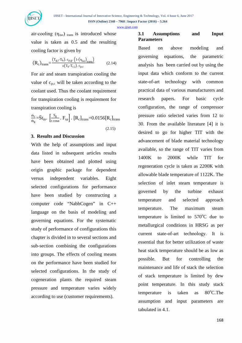
• Variation of plant efficiency for
varying TIT
Fig. 4.13 shows the effect of varying
turbine inlet temperature (TIT) on plant
efficiency. It is observed that plant
efficiency increases with the increase in
TIT at constant rp for all cooling means.
For higher value of TIT gas turbine output
is higher and to achieve higher TIT
although plant specific fuel consumption at
combustor is higher but compressor work
requirement is constant for constant rp so it
increases the plant efficiency. For AICC
higher value of plant efficiency may be
observed while lower value is for CLSC.
• Variation of specific plant specific
fuel consumption for varying TIT
Fig. 4.14 shows the effect of varying
turbine inlet temperature (TIT) on plant
specific plant specific fuel consumption. It
is observed that specific plant specific fuel
consumption decreases with the increase in
TIT at constant rp for all cooling means. It
is because of the fact that specific plant
specific fuel consumption is inversely
proportional to plant efficiency. As in fig.
350 400 450 500 550 600 650 700 750 800 850
34
36
38
40
42
44
46
48
TIT = 1400K - 2000K
2000
1900
1800
1700
1600
1500
1400
rp= 30
rp= 27rp= 24
rp= 21rp= 18
rp= 15
rp= 12Plan
t effi
cien
cy (%
)
Plant specific work (kJ/kg)

IJISET - International Journal of Innovative Science, Engineering & Technology, Vol. 4 Issue 6, June 2017
ISSN (Online) 2348 – 7968 | Impact Factor (2016) – 5.264
www.ijiset.com
172
4.13 plant efficiency increases with the
TIT thus the specific plant specific fuel
consumption decreases with increase in
TIT. Highest specific plant specific fuel
consumption is seen with CLSC and
lowest specific plant specific fuel
consumption is seen with AICC.
• Variation of mass of coolant to gas
�𝐦𝐜 𝐦𝐠⁄ � for varying TIT
The coolant requirement increases with
increase in TIT for all types of cooling
considered. The minimum coolant
requirement is found to be in the case of
STC. The maximum cooling requirement
is found in the case of AICC and it
increases faster with increase in TIT as
compared to other cooling means. The
results of CLSC and SICC overlap each
other because the values of specific heat of
steam, entering to the gas turbine blades
and heat exchanger (blades) effectiveness
are same in both the cases. Fig. 4.15 shows
that if TIT is increased beyond 1700 K
(temperature level in modern turbines),
steam cooling is the best coolant option
whereas for air-cooling ATC, followed by
AFC are the next options. ATC offers
reduced heat transfer due to transpired
coolant film completely shrouding the
blade surface. Similarly, AFC also
provides coolant film over blade surface,
which acts as thermal barrier for the hot
gas.
Figure 4.1 Basic gas turbine with convection cooling.
Figure 4.2 Basic gas turbine withfilm cooling.
Figure 4.3 Basic gas turbine with transpiration cooling.
350 400 450 500 550 600 650 700 750 800 850
34
36
38
40
42
44
46
48
TIT = 1400K - 2000K
2000
1900
1800
1700
1600
1500
1400
rp= 30
rp= 27rp= 24
rp= 21rp= 18
rp= 15
rp= 12
Plan
t eff
icie
ncy
(%)
Plant specific work (kJ/kg)
350 400 450 500 550 600 650 700 750 800 850
34
36
38
40
42
44
46
48
TIT = 1400K - 2000K
2000
1900
1800
1700
1600
1500
1400
rp= 30
rp= 27rp= 24
rp= 21rp= 18
rp= 15
rp= 12
Plan
t eff
icie
ncy
(%)
Plant specific work (kJ/kg)

IJISET - International Journal of Innovative Science, Engineering & Technology, Vol. 4 Issue 6, June 2017
ISSN (Online) 2348 – 7968 | Impact Factor (2016) – 5.264
www.ijiset.com
173
Figure 4.4 Basic gas turbine with open loop steam convection cooling.
Figure 4.5 Basic gas turbine with open loop steam film cooling.
Figure 4.6 Basic gas turbine with open loop steam transpiration cooling.
Figure 4.7 Basic gas turbine with closed loop steam convection cooling.
Figure 4.8 Compressor pressure ratio vs. Plant specific work with different cooling means for basic gas turbine.
Figure 4.9 Compressor pressure ratios vs. Plant efficiency with different cooling means for basic gas turbine.
350 400 450 500 550 600 650 700 750 800 850 900 950
34
36
38
40
42
44
46
48
TIT = 1400K - 2000K
2000
1900
1800
1700
1600
1500
1400 rp= 30
rp= 27rp= 24
rp= 21rp= 18
rp= 15
rp= 12
Plan
t effi
cien
cy (%
)
Plant specific work (kJ/kg)
350 400 450 500 550 600 650 700 750 800 850 900 950
34
36
38
40
42
44
46
48
TIT = 1400K - 2000K
200019
0018
0017
0016
0015
0014
00 rp= 30
rp= 27rp= 24
rp= 21rp= 18
rp= 15
rp= 12
Plan
t eff
icie
ncy
(%)
Plant specific work (kJ/kg)
350 400 450 500 550 600 650 700 750 800 850 900 950
34
36
38
40
42
44
46
48
TIT = 1400K - 2000K
200019
0018
0017
0016
0015
0014
00 rp= 30
rp= 27rp= 24
rp= 21rp= 18
rp= 15
rp= 12
Plan
t eff
icie
ncy
(%)
Plant specific work (kJ/kg)
350 400 450 500 550 600 650 700 750 800 850
34
36
38
40
42
44
46
48
TIT = 1400K - 2000K
200019
00180017
0016
0015
0014
00
rp= 30
rp= 27rp= 24
rp= 21rp= 18
rp= 15rp= 12
Plan
t effi
cien
cy (%
)
Plant specific work (kJ/kg)
10 12 14 16 18 20 22 24 26 28 30 32 34540550560570580590600610620630640650660 TIT = 1700K; Tb= 1122K
AICC AFC ATC SICC SFC STC CLSC
Plan
t spe
cific
wor
k (k
J/kg
)
Compressor pressure ratio (rp)
10 12 14 16 18 20 22 24 26 28 30 32 3434353637383940414243444546 TIT = 1700K; Tb= 1122K
AICC AFC ATC SICC SFC STC CLSCPl
ant e
ffici
ency
(%)
Compressor pressure ratio (rp)

IJISET - International Journal of Innovative Science, Engineering & Technology, Vol. 4 Issue 6, June 2017
ISSN (Online) 2348 – 7968 | Impact Factor (2016) – 5.264
www.ijiset.com
174
Figure 4.10 Compressor pressure ratio vs. sfc with different cooling means for basic gas turbine.
Figure 4.11 Compressor pressure ratio vs mRcR/mRgR with different cooling means for basic gas turbine.
Figure 4.12 TIT vs. plant specific work with different cooling means for basic gas turbine.
Figure 4.13 TIT vs. plant efficiency with different cooling means for basic gas turbine.
Figure 4.14 TIT vs. SFC with different cooling means for basic gas turbine.
Figure 4.15 TIT vs. mRcR/mRgR with different cooling means for basic gas Turbine.
4. Conclusion
10 12 14 16 18 20 22 24 26 28 30 32 340.18
0.19
0.20
0.21
0.22
0.23
0.24
0.25 TIT = 1700K; Tb= 1122K
AICC AFC ATC SICC SFC STC CLSC
Spec
ific
fuel
con
sum
ptio
n (k
g/kW
-Hr)
Compressor pressure ratio (rp)
10 12 14 16 18 20 22 24 26 28 30 32 34123456789
10 TIT = 1700K; Tb= 1122K
AICC AFC ATC SICC SFC STC CLSC
mc/m
g (%
)
Compressor pressure ratio (rp)
1400 1500 1600 1700 1800 1900 2000350400450500550600650700750800850 rp= 21; Tb= 1122K
AICC AFC ATC SICC SFC STC CLSC
Plan
t spe
cific
wor
k (k
J/kg
)
Turbine inlet temperature (K)
1400 1500 1600 1700 1800 1900 2000 210038
39
40
41
42rp= 21; Tb= 1122K
AICC AFC ATC SICC SFC STC CLSC
Plan
t eff
icie
ncy
(%)
Turbine inlet temperature (K)
1400 1500 1600 1700 1800 1900 2000 21000.19
0.20
0.21
0.22 rp= 21; Tb= 1122K
AICC AFC ATC SICC SFC STC CLSC
Spec
ific
fuel
con
sum
ptio
n (k
g/kW
-Hr)
Turbine inlet temperature (K)
1400 1500 1600 1700 1800 1900 2000 21000
2
4
6
8
10
12
14 rp= 21; Tb= 1122K
AICC AFC ATC SICC SFC STC CLSC
mc/m
g (%
)
Turbine inlet temperature (K)

IJISET - International Journal of Innovative Science, Engineering & Technology, Vol. 4 Issue 6, June 2017
ISSN (Online) 2348 – 7968 | Impact Factor (2016) – 5.264
www.ijiset.com
175
Based on mathematical modeling of
various elements of the cogeneration cycle
and governing equations, using seven
cooling means of gas turbine blade cooling
has been developed in C++ language to
predict the thermodynamic performance of
eight configurations of cogeneration plants.
For all seven cooling means, the coolant
requirement increases linearly with TIT as
expected. The effect of rRpR on cooling flow
requirement is negligible for all cooling
means. The behavior of basic gas turbine
(BGT) plant specific work with rRpR at higher
and lower range of TIT is different. For
higher range of TIT it increases with rRpR
while for lower range of TIT it first
increases and then decreases for all seven
cooling means. BGT plant efficiency
increases linearly with increase in TIT at
any rRp Rfor all seven cooling means. For
basic gas turbine plant efficiency is higher
with AICC and minimum with CLSC
while plant specific work is higher with
SICC and minimum with AICC at constant
TIT = 1700K.
References:
[1] Shukla, A.K, Singh, O., “Performance evaluation of steam injected gas turbine based power plant with inlet evaporative cooling”, Applied Thermal Engineering, Vol. 102, June 2016
[2] Ahmed H., Yahya R. and Abraham E., “Feasibility of using vapor compression refrigeration system for cooling steam
plant condenser”, Applied Thermal Engineering, Vol. 106, August 2016.
[3] Alaa A. El-Shazly, Mohamed E., Medhat M. S. and Wael M. El-Maghlany, “Gas turbine performance enhancement via utilizing different integrated turbine inlet cooling techniques”, Alexandria Engineering Journal, Vol. 55, Issue 3, September 2016.
[4] Sanjay, Singh O. and Prasad B.N., “Comparative performance analysis of cogeneration gas turbine cycle for different blade cooling means”, International Journal of Thermal Sciences, Vol. 48, July 2009, pp. 1432-1440.
[5] Ping Dong, Qiang Wang, Zhaoyuan Guo, Hongyan Huang and Guotai Feng, “Conjugate Calculation of Gas Turbine Vanes Cooled with Leading Edge Films”, Chinese Journal of Aeronautics, Vol. 22, Issue 2, April 2009, pp. 145-152.
[6] Ting Wang and Xianchang Li, “Mist film cooling simulation at gas turbine operating conditions”, International Journal of Heat and Mass Transfer, Vol. 51, Issues 21-22, October 2008, pp. 5305-5317.
[7] Zigong Gao, Diganta P. N. and Je-Chin Han, “Film cooling on a gas turbine blade pressure side or suction side with axial shaped holes” International Journal of Heat and Mass Transfer, Vol. 51, Issues 9-10, May 2008, pp. 2139-2152.
[8] Vaidyanathan Krishnan, Sanjeev Bharani, Kapat J.S., Sohn Y.H. and Desai V.H., “A simplistic model to study the influence of film cooling on low temperature hot corrosion rate in coal gas/syngas fired gas turbines”, International Journal of Heat and Mass Transfer, Vol. 51, Issues 5-6, March 2008, pp. 1049-1060.
[9] Sanjay, Singh O. and Prasad B.N., “Influence of different means of turbine blade cooling on the thermodynamic

IJISET - International Journal of Innovative Science, Engineering & Technology, Vol. 4 Issue 6, June 2017
ISSN (Online) 2348 – 7968 | Impact Factor (2016) – 5.264
www.ijiset.com
176
performance of combined cycle”, Applied Thermal Engineering, Vol. 28, 2008, pp. 2315–2326.
[10] Sanjay, Singh O. and Prasad B.N., “Energy and exergy analysis of steam cooled reheat gas-steam combined cycle”, Applied Thermal Engineering, Vol. 27, 2007, pp. 2779–2790.
[11] Louis J.F., Hiraoka K., and El-Masri M.A., “A comparative study of influence of different means of turbine cooling on gas turbine performance”, ASME Paper no. 83-GT-180, 2003.
[12] Horlock, J.H., Watson, D.T., and Jones, T.V., “Limitation on Gas Turbine Performance Imposed by Large Turbine Cooling Flows”, ASME Journal of Engg Gas Turbines Power, Vol.123, 2001, pp. 487-493.
[13] El-Masri M.A., “On Thermodynamics of Gas Turbine Cycles: Part 3- Thermodynamic Potential and Limitations of Cooled Reheated-Gas-Turbine Combined Cycles”, ASME Journal of Engineering for Gas Turbine and Power, Vol.108, 1986, pp. 160-169.
[14] Bolland O. and Stadaas J. F., “Comparative Evaluation of Combined Cycles and Gas Turbine Systems with Water Injection, Steam Injection, and Recuperation”, Journal of engineering for gas turbines and power, Vol. 117, 1995, pp. 138-145.
[15] Yadav R., “Effect of Bottoming Cycle Alternatives on the Performance of Combined Cycle”, Proceeding of ASME Turbo. Expo 2003 June 16-19, Geogia Atlanta, USA (GT 2003 –38052), 2003.
AUTHORS
Ankita Sharma received the Bachelors of Engineering
degree in Mechanical Engineering from Institute of Technology, Korba, Chhattisgarh Swami Vivekananda Technical University, Bhilai, Chhattisgarh, India in 2014 and Masters of Technology in Heat Power and thermal Engineering from Technocrats Institute of Technology, Bhopal, India in 2016. He had worked in Govt. Polytechnic College, Korba (C.G) as an lecturer in Mechanical Engineering
department.
Shubham Tiwari received the Bachelors of Engineering degree in Mechanical Engineering from Annamalai University, Tamilnadu, India
in 2013 and Masters of Technology in Heat Power and thermal Engineering from Technocrats Institute of Technology, Bhopal, India in 2016. He had worked in Institute of Technology, Korba (C.G) as an lecturer in Mechanical Engineering department.
Laxmi Kant Sahu received the Bachelors of Engineering degree in Mechanical Engineering from Govt. Engineering College,
Bilaspur, Chhattisgarh Swami Vivekananda Technical University, Bhilai, Chhattisgarh, India in 2010 and Masters of Technology in Machine Design from Guru Ghasidas Vishwavidyalaya (a central university), Bilaspur, Chhattisgarh, India in 2014. He had worked in Institute of Technology, Korba (C.G) as an Assistant Professor in Mechanical Engineering department.


![Optimising The Parameters For The Congo Red Dye …ijiset.com/vol4/v4s1/IJISET_V4_I01_01.pdf · 2017-01-09 · found [14] suitable for the removal of congo red from dye waste water](https://img.pdfslide.us/doc/110x75/5f427cd47965bc770d0f9e86/optimising-the-parameters-for-the-congo-red-dye-2017-01-09-found-14-suitable.jpg)

![Solving Economic Dispatch Problems By Using Grey Wolf ...ijiset.com/vol4/v4s9/IJISET_V4_I09_17.pdf · [7]Pradhan, Moumita, Provas Kumar Roy, and Tandra Pal. "Grey wolf optimization](https://img.pdfslide.us/doc/110x75/605b856a77fdd420854ed08e/solving-economic-dispatch-problems-by-using-grey-wolf-7pradhan-moumita-provas.jpg)