Embed Size (px)
Citation preview
Chinese Journal of Aeronautics, (2014),27(5): 1051–1061
Chinese Society of Aeronautics and Astronautics& Beihang University
Chinese Journal of Aeronautics
Parametric analyses for synthetic jet control
on separation and stall over rotor airfoil
* Corresponding author. Tel.: +86 25 84893753.
E-mail address: [email protected] (Q. Zhao).
Peer review under responsibility of Editorial Committee of CJA.
Production and hosting by Elsevier
http://dx.doi.org/10.1016/j.cja.2014.03.0231000-9361 ª 2014 Production and hosting by Elsevier Ltd. on behalf of CSAA & BUAA. Open access under CC BY-NC-ND license.
Zhao Guoqing, Zhao Qijun *
National Key Laboratory of Rotorcraft Aeromechanics, Nanjing University of Aeronautics and Astronautics, Nanjing 210016, China
Received 11 October 2013; revised 27 November 2013; accepted 20 December 2013
Available online 15 March 2014
KEYWORDS
Flow control;
Flow separation;
Parametric analysis;
Rotor;
Synthetic jet
Abstract Numerical simulations are performed to investigate the effects of synthetic jet control on
separation and stall over rotor airfoils. The preconditioned and unsteady Reynolds-averaged
Navier–Stokes equations coupled with a k � x shear stream transport turbulence model are
employed to accomplish the flowfield simulation of rotor airfoils under jet control. Additionally,
a velocity boundary condition modeled by a sinusoidal function is developed to fulfill the perturba-
tion effect of periodic jets. The validity of the present CFD procedure is evaluated by the simulated
results of an isolated synthetic jet and the jet control case for airfoil NACA0015. Then, parametric
analyses are conducted specifically for an OA213 rotor airfoil to investigate the effects of jet param-
eters (forcing frequency, jet location and momentum coefficient, jet direction, and distribution of jet
arrays) on the control effect of the aerodynamic characteristics of a rotor airfoil. Preliminary results
indicate that the efficiency of jet control can be improved with specific frequencies (the best lift-drag
ratio at F+ = 2.0) and jet angles (40� or 75�) when the jets are located near the separation point of
the rotor airfoil. Furthermore, as a result of a suitable combination of jet arrays, the lift coefficient
of the airfoil can be improved by nearly 100%, and the corresponding drag coefficient decreased by
26.5% in comparison with the single point control case.ª 2014 Production and hosting by Elsevier Ltd. on behalf of CSAA & BUAA.Open access under CC BY-NC-ND license.
1. Introduction
The retreating blades of a rotor are usually manipulated withlarge pitch angles. Therefore, flow separation and dynamic
stall occur frequently during the forward flight of a helicopter.
The dynamic stall of retreating blades is one of the typicalunsteady aerodynamic characteristics of a helicopter rotor,and it induces the loss of lift, the increase of drag and pitching
moment of the rotor, which significantly impacts the aerody-namic performance of a helicopter, threatening the stabilityof the rotor and restricting the speed envelope of the helicop-
ter. Strategies for delaying the flow separation and stall of therotor (airfoil) and further extending the post stall envelope ofthe rotor (airfoil) have been an active topic in the field of heli-copter technology for many years. The active flow control
(AFC) method is a new approach in improving the aerody-namic characteristics of the rotor (airfoil), and is consideredone of the innovative technologies for the next generation of
1052 G. Zhao, Q. Zhao
rotorcraft.1 Furthermore, AFC has the potential to signifi-cantly improve the aerodynamic characteristics of airfoilswithout any deflecting control surfaces, which helps to retain
a minimum radar cross section.Recently, a novel method of AFC by using synthetic jet actu-
ators has been experimentally demonstrated to be one of the
most promising AFC methods, especially for rotary wingaircraft.2 It is because the synthetic jet actuator generates ahigh-frequency jet from the flow with zero net mass injection.
The synthetic jet actuator was manufactured by Smith andGlezer in 1994. A synthetic jet is created by driving one side ofa cavity using a piston or piezoelectric diaphragm in a periodicmanner, and the jet is synthesized by the interactions of counter
rotating vortex pairs formed at the edge of an orifice.3 The fluiddriven out of the cavity forms a shear layer between the expelledfluid and the surrounding fluid. This layer of vorticity rolls up to
form two parallel vortices in the case of a rectangular actuator.By the time the diaphragm begins to move away from the orificeto pull the fluid back into the cavity, the vortices havemoved far
away enough. Thus a train of vortex pairs are created by theactuator. Therefore, a synthetic jet requires no mass injection,but only electrical power. It is feasible for the flow control on
the rotor and airfoil. Many experimental and numerical resultsdemonstrate that a synthetic jet with appropriate combinationsof parameters can reattach the separation flow over the rotorairfoils or delay its separation,1,4–10 resulting in improving the
aerodynamic characteristics of airfoils and delaying stall byenlarging the stall angle.
Seifert et al. carried out active flow control experiments on
a NACA 0015 airfoil by placing a synthetic jet actuator at theleading edge,11 and the results indicated that a jet placed justupstream of the separation location was effective on control-
ling the flow separation of an airfoil. In the aspect of numericalsimulations for synthetic jet control, Donovan et al. usedReynolds-averaged Navier–Stokes (RANS) equations to inves-
tigate the effect of synthetic jet on the flowfield of an airfoil justaccording to the experiments,12 and good agreements wereobtained between the numerical results and the test data.The results give us the confidence that the RANS approach
can be used to investigate the active flow control on rotor air-foils by using unsteady synthetic jets. Lorber et al. conductednumerical and experimental investigations on avoiding or
delaying retreating blade stalls by a directed synthetic jet(DSJ) over helicopter rotor airfoil SC2110.13 The resultsindicated that the DSJ was valuable on controlling the post
and dynamic stall of a rotor retreating blade. Kim et al.numerically investigated the flow control using a synthetic jetto improve the aerodynamic performance of tiltrotor airfoilsunder various flight conditions,14 and the calculated results
revealed that the download could be efficiently reduced byusing both the leading edge and trailing edge jets in the hover-ing flight mode.
Although the synthetic jet has a good potential in applica-tions for active flow control on rotors and airfoils, there aresome problems that have not been resolved.15 The interactions
of jet vortex pairs with low speed and viscous boundary layerare still not very clear yet, and the applications of the syntheticjet on a rotor airfoil still remain theoretical because of the large
number of controlling parameters,16 such as actuator location,forcing frequency, blowing magnitude and direction, etc.Additionally, there are some disagreements among differentreferences. For example, He et al. pointed out that the
synthetic jet was not sensitive to the blowing directions,16 whileHassan considered that the synthetic jet had the best perfor-mance when the jet angle was about 25�.17 Furthermore, the
numerical conclusions of Hassan preliminarily indicated thata jet array with two synthetic jet actuators could help improvethe benefits of the enhancement of aerodynamic characteristics
for rotor airfoils.17 However, the research work only involveda two point AFC control with the actuators at a fixed location,while the control mechanism of synthetic jet arrays at various
locations and with more than two actuators has not been takeninto consideration.
This paper aims at obtaining in depth the effects of severalparameters (especially jet angle and jet array) about the syn-
thetic jet on the control efficiency of the aerodynamic charac-teristics of a rotor airfoil (measured by the increment ordecrement rates of the aerodynamic forces of the rotor airfoil
under control compared with the baseline case or a specified jetcontrolled case). Quite a number of numerical simulationshave been conducted to investigate the effects of synthetic jet
control on the separation and stall over rotor airfoils. Toimprove the accuracy of prediction on low speed flow inducedby a synthetic jet with strong adverse pressure gradients and
pressure-induced boundary layer separation, preconditionedRANS equations and a k � x shear stream transport (SST)turbulent model are adopted to investigate the characteristicsof the synthetic jet and the effectiveness of periodic jet control
on the separation and post-stall for rotor airfoils. The feasibil-ity and efficiency of this method are evaluated and demon-strated. Then, based on the present method, parametric
analyses of synthetic jet control for rotor airfoil OA213 arecarried out to study the control mechanism of the syntheticjet on the aerodynamic characteristics of the rotor airfoil,
and some significant conclusions are obtained.
2. Numerical methods
2.1. Governing equations
Based on the CFD method developed by the author of thispaper,18 and to overcome the stiffness of the solution systemand improve the computational efficiency when the local Machnumber is low, flows around a rotor including unsteady pertur-
bations induced by a synthetic jet are simulated by solving theunsteady preconditioned RANS equations. The precondi-tioned Navier–Stokes equations in a control volume X in the
integral form by using pressure p, flow velocity u, v, and tem-perature T as parameters W= [p, u, v, T]T, can be written as
C@
@t
ZWdXþ
IðF� FvÞ � ndS ¼ 0 ð1Þ
where F, Fv denote respectively the vectors of convective and
viscous fluxes, n is the unit vector normal to surface elementdS, C the preconditioning matrix, and the Weiss–Smith matrixis employed in this paper.19
C ¼
H 0 0 qT
Hu q 0 qTu
Hv 0 q qTv
HH� 1 qu qv qcp þ qTH
26664
37775 ð2Þ
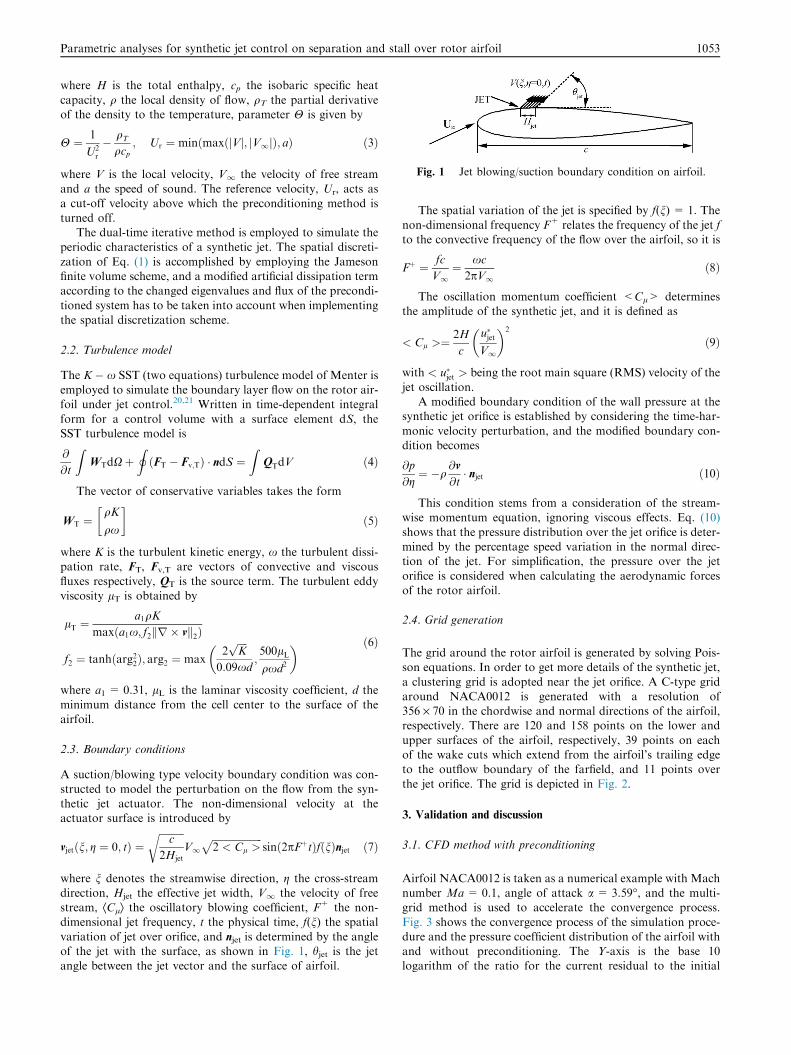
Fig. 1 Jet blowing/suction boundary condition on airfoil.
Parametric analyses for synthetic jet control on separation and stall over rotor airfoil 1053
where H is the total enthalpy, cp the isobaric specific heat
capacity, q the local density of flow, qT the partial derivativeof the density to the temperature, parameter H is given by
H ¼ 1
U2r
� qT
qcp; Ur ¼ minðmaxðjVj; jV1jÞ; aÞ ð3Þ
where V is the local velocity, V1 the velocity of free streamand a the speed of sound. The reference velocity, Ur, acts as
a cut-off velocity above which the preconditioning method isturned off.
The dual-time iterative method is employed to simulate theperiodic characteristics of a synthetic jet. The spatial discreti-
zation of Eq. (1) is accomplished by employing the Jamesonfinite volume scheme, and a modified artificial dissipation termaccording to the changed eigenvalues and flux of the precondi-
tioned system has to be taken into account when implementingthe spatial discretization scheme.
2.2. Turbulence model
The K � x SST (two equations) turbulence model of Menter isemployed to simulate the boundary layer flow on the rotor air-foil under jet control.20,21 Written in time-dependent integral
form for a control volume with a surface element dS, theSST turbulence model is
@
@t
ZWTdXþ
IðFT � Fv;TÞ � ndS ¼
ZQTdV ð4Þ
The vector of conservative variables takes the form
WT ¼qK
qx
� �ð5Þ
where K is the turbulent kinetic energy, x the turbulent dissi-pation rate, FT, Fv,T are vectors of convective and viscous
fluxes respectively, QT is the source term. The turbulent eddyviscosity lT is obtained by
lT ¼a1qK
maxða1x; f2kr � vk2Þ
f2 ¼ tanhðarg22Þ; arg2 ¼ max2ffiffiffiffiKp
0:09xd;500lL
qxd2
� � ð6Þ
where a1 = 0.31, lL is the laminar viscosity coefficient, d the
minimum distance from the cell center to the surface of theairfoil.
2.3. Boundary conditions
A suction/blowing type velocity boundary condition was con-structed to model the perturbation on the flow from the syn-thetic jet actuator. The non-dimensional velocity at theactuator surface is introduced by
vjetðn; g ¼ 0; tÞ ¼ffiffiffiffiffiffiffiffiffiffic
2Hjet
rV1
ffiffiffiffiffiffiffiffiffiffiffiffiffiffiffiffiffiffiffiffi2 < Cl >
psinð2pFþtÞfðnÞnjet ð7Þ
where n denotes the streamwise direction, g the cross-streamdirection, Hjet the effective jet width, V1 the velocity of freestream, ÆClæ the oscillatory blowing coefficient, F+ the non-dimensional jet frequency, t the physical time, f(n) the spatial
variation of jet over orifice, and njet is determined by the angleof the jet with the surface, as shown in Fig. 1, hjet is the jetangle between the jet vector and the surface of airfoil.
The spatial variation of the jet is specified by f(n) = 1. The
non-dimensional frequency F+ relates the frequency of the jet fto the convective frequency of the flow over the airfoil, so it is
Fþ ¼ fc
V1¼ xc
2pV1ð8Þ
The oscillation momentum coefficient <Cl> determinesthe amplitude of the synthetic jet, and it is defined as
< Cl >¼2H
c
u�jetV1
� �2
ð9Þ
with < u�jet > being the root main square (RMS) velocity of the
jet oscillation.A modified boundary condition of the wall pressure at the
synthetic jet orifice is established by considering the time-har-
monic velocity perturbation, and the modified boundary con-dition becomes
@p
@g¼ �q
@v
@t� njet ð10Þ
This condition stems from a consideration of the stream-wise momentum equation, ignoring viscous effects. Eq. (10)
shows that the pressure distribution over the jet orifice is deter-mined by the percentage speed variation in the normal direc-tion of the jet. For simplification, the pressure over the jet
orifice is considered when calculating the aerodynamic forcesof the rotor airfoil.
2.4. Grid generation
The grid around the rotor airfoil is generated by solving Pois-son equations. In order to get more details of the synthetic jet,
a clustering grid is adopted near the jet orifice. A C-type gridaround NACA0012 is generated with a resolution of356 · 70 in the chordwise and normal directions of the airfoil,respectively. There are 120 and 158 points on the lower and
upper surfaces of the airfoil, respectively, 39 points on eachof the wake cuts which extend from the airfoil’s trailing edgeto the outflow boundary of the farfield, and 11 points over
the jet orifice. The grid is depicted in Fig. 2.
3. Validation and discussion
3.1. CFD method with preconditioning
Airfoil NACA0012 is taken as a numerical example with Machnumber Ma= 0.1, angle of attack a = 3.59�, and the multi-grid method is used to accelerate the convergence process.
Fig. 3 shows the convergence process of the simulation proce-dure and the pressure coefficient distribution of the airfoil withand without preconditioning. The Y-axis is the base 10logarithm of the ratio for the current residual to the initial
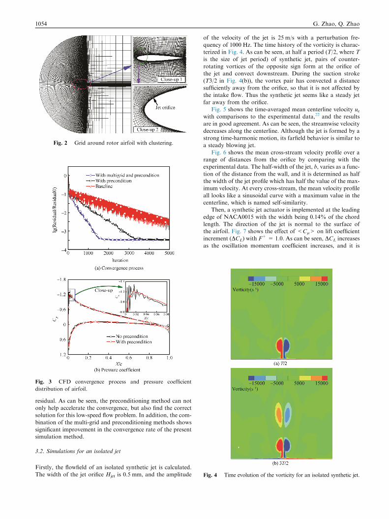
Fig. 2 Grid around rotor airfoil with clustering.
Fig. 3 CFD convergence process and pressure coefficient
distribution of airfoil.
Fig. 4 Time evolution of the vorticity for an isolated synthetic jet.
1054 G. Zhao, Q. Zhao
residual. As can be seen, the preconditioning method can notonly help accelerate the convergence, but also find the correctsolution for this low-speed flow problem. In addition, the com-
bination of the multi-grid and preconditioning methods showssignificant improvement in the convergence rate of the presentsimulation method.
3.2. Simulations for an isolated jet
Firstly, the flowfield of an isolated synthetic jet is calculated.The width of the jet orifice Hjet is 0.5 mm, and the amplitude
of the velocity of the jet is 25 m/s with a perturbation fre-quency of 1000 Hz. The time history of the vorticity is charac-terized in Fig. 4. As can be seen, at half a period (T/2, where T
is the size of jet period) of synthetic jet, pairs of counter-rotating vortices of the opposite sign form at the orifice ofthe jet and convect downstream. During the suction stroke
(T3/2 in Fig. 4(b)), the vortex pair has convected a distancesufficiently away from the orifice, so that it is not affected bythe intake flow. Thus the synthetic jet seems like a steady jet
far away from the orifice.Fig. 5 shows the time-averaged mean centerline velocity uc
with comparisons to the experimental data,22 and the resultsare in good agreement. As can be seen, the streamwise velocity
decreases along the centerline. Although the jet is formed by astrong time-harmonic motion, its farfield behavior is similar toa steady blowing jet.
Fig. 6 shows the mean cross-stream velocity profile over arange of distances from the orifice by comparing with theexperimental data. The half-width of the jet, b, varies as a func-
tion of the distance from the wall, and it is determined as halfthe width of the jet profile which has half the value of the max-imum velocity. At every cross-stream, the mean velocity profile
all looks like a sinusoidal curve with a maximum value in thecenterline, which is named self-similarity.
Then, a synthetic jet actuator is implemented at the leadingedge of NACA0015 with the width being 0.14% of the chord
length. The direction of the jet is normal to the surface ofthe airfoil. Fig. 7 shows the effect of <Cl> on lift coefficientincrement (DCL) with F+ = 1.0. As can be seen, DCL increases
as the oscillation momentum coefficient increases, and it is
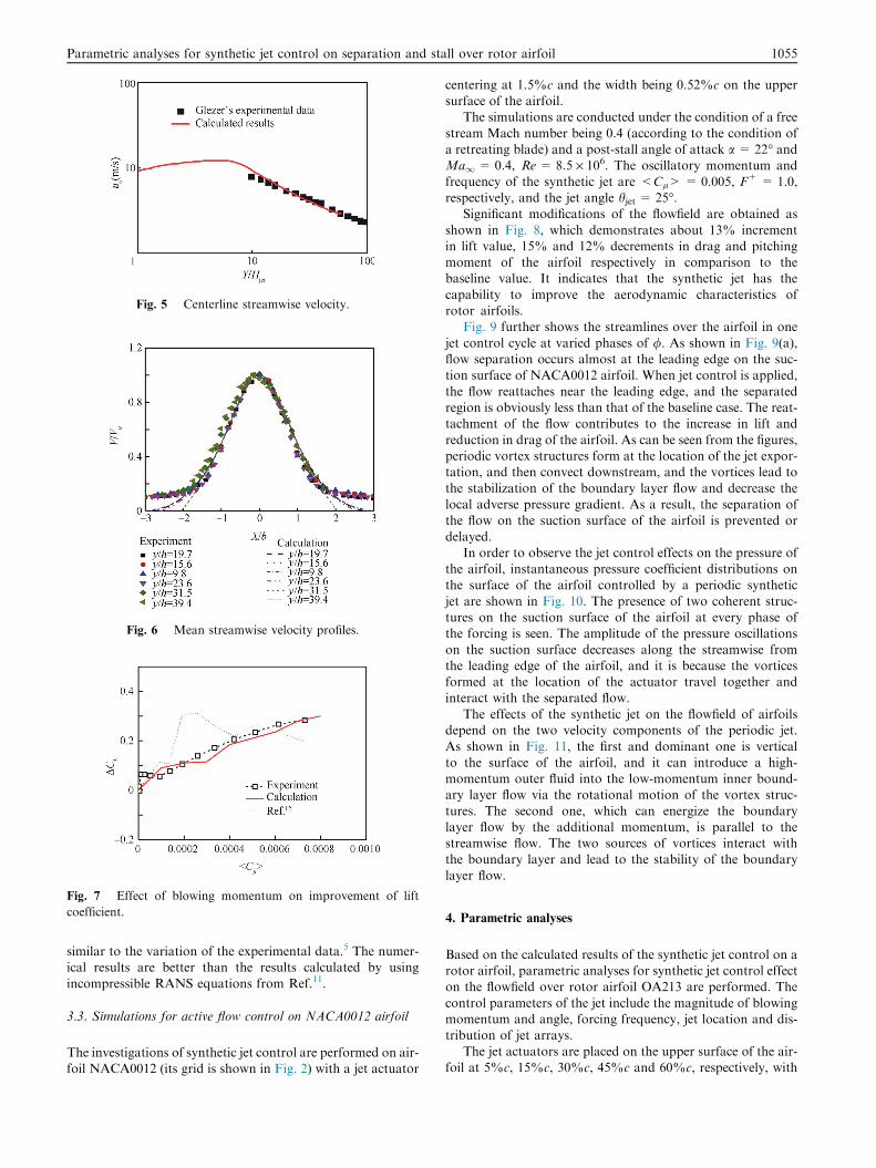
Fig. 5 Centerline streamwise velocity.
Fig. 6 Mean streamwise velocity profiles.
Fig. 7 Effect of blowing momentum on improvement of lift
coefficient.
Parametric analyses for synthetic jet control on separation and stall over rotor airfoil 1055
similar to the variation of the experimental data.5 The numer-ical results are better than the results calculated by using
incompressible RANS equations from Ref.11.
3.3. Simulations for active flow control on NACA0012 airfoil
The investigations of synthetic jet control are performed on air-foil NACA0012 (its grid is shown in Fig. 2) with a jet actuator
centering at 1.5%c and the width being 0.52%c on the uppersurface of the airfoil.
The simulations are conducted under the condition of a free
stream Mach number being 0.4 (according to the condition ofa retreating blade) and a post-stall angle of attack a = 22� andMa1= 0.4, Re= 8.5 · 106. The oscillatory momentum and
frequency of the synthetic jet are <Cl> = 0.005, F+ = 1.0,respectively, and the jet angle hjet = 25�.
Significant modifications of the flowfield are obtained as
shown in Fig. 8, which demonstrates about 13% incrementin lift value, 15% and 12% decrements in drag and pitchingmoment of the airfoil respectively in comparison to thebaseline value. It indicates that the synthetic jet has the
capability to improve the aerodynamic characteristics ofrotor airfoils.
Fig. 9 further shows the streamlines over the airfoil in one
jet control cycle at varied phases of /. As shown in Fig. 9(a),flow separation occurs almost at the leading edge on the suc-tion surface of NACA0012 airfoil. When jet control is applied,
the flow reattaches near the leading edge, and the separatedregion is obviously less than that of the baseline case. The reat-tachment of the flow contributes to the increase in lift and
reduction in drag of the airfoil. As can be seen from the figures,periodic vortex structures form at the location of the jet expor-tation, and then convect downstream, and the vortices lead tothe stabilization of the boundary layer flow and decrease the
local adverse pressure gradient. As a result, the separation ofthe flow on the suction surface of the airfoil is prevented ordelayed.
In order to observe the jet control effects on the pressure ofthe airfoil, instantaneous pressure coefficient distributions onthe surface of the airfoil controlled by a periodic synthetic
jet are shown in Fig. 10. The presence of two coherent struc-tures on the suction surface of the airfoil at every phase ofthe forcing is seen. The amplitude of the pressure oscillations
on the suction surface decreases along the streamwise fromthe leading edge of the airfoil, and it is because the vorticesformed at the location of the actuator travel together andinteract with the separated flow.
The effects of the synthetic jet on the flowfield of airfoilsdepend on the two velocity components of the periodic jet.As shown in Fig. 11, the first and dominant one is vertical
to the surface of the airfoil, and it can introduce a high-momentum outer fluid into the low-momentum inner bound-ary layer flow via the rotational motion of the vortex struc-
tures. The second one, which can energize the boundarylayer flow by the additional momentum, is parallel to thestreamwise flow. The two sources of vortices interact withthe boundary layer and lead to the stability of the boundary
layer flow.
4. Parametric analyses
Based on the calculated results of the synthetic jet control on arotor airfoil, parametric analyses for synthetic jet control effecton the flowfield over rotor airfoil OA213 are performed. The
control parameters of the jet include the magnitude of blowingmomentum and angle, forcing frequency, jet location and dis-tribution of jet arrays.
The jet actuators are placed on the upper surface of the air-foil at 5%c, 15%c, 30%c, 45%c and 60%c, respectively, with
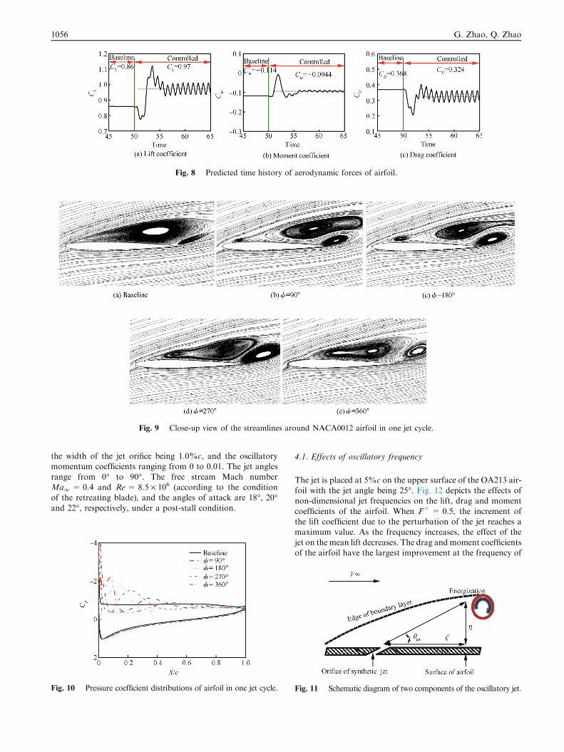
Fig. 8 Predicted time history of aerodynamic forces of airfoil.
Fig. 9 Close-up view of the streamlines around NACA0012 airfoil in one jet cycle.
1056 G. Zhao, Q. Zhao
the width of the jet orifice being 1.0%c, and the oscillatorymomentum coefficients ranging from 0 to 0.01. The jet angles
range from 0� to 90�. The free stream Mach numberMa1= 0.4 and Re= 8.5 · 106 (according to the conditionof the retreating blade), and the angles of attack are 18�, 20�and 22�, respectively, under a post-stall condition.
Fig. 10 Pressure coefficient distributions of airfoil in one jet cycle.
4.1. Effects of oscillatory frequency
The jet is placed at 5%c on the upper surface of the OA213 air-foil with the jet angle being 25�. Fig. 12 depicts the effects ofnon-dimensional jet frequencies on the lift, drag and moment
coefficients of the airfoil. When F+ = 0.5, the increment ofthe lift coefficient due to the perturbation of the jet reaches amaximum value. As the frequency increases, the effect of the
jet on the mean lift decreases. The drag and moment coefficientsof the airfoil have the largest improvement at the frequency of
Fig. 11 Schematic diagram of two components of the oscillatory jet.
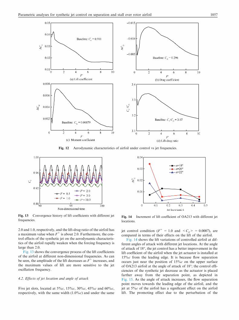
Fig. 12 Aerodynamic characteristics of airfoil under control vs jet frequencies.
Fig. 13 Convergence history of lift coefficients with different jet
frequencies.Fig. 14 Increment of lift coefficient of OA213 with different jet
locations.
Parametric analyses for synthetic jet control on separation and stall over rotor airfoil 1057
2.0 and 1.0, respectively, and the lift-drag ratio of the airfoil has
a maximum value when F+ is about 2.0. Furthermore, the con-trol effects of the synthetic jet on the aerodynamic characteris-tics of the airfoil rapidly weaken when the forcing frequency is
large than 2.0.Fig. 13 shows the convergence process of the lift coefficients
of the airfoil at different non-dimensional frequencies. As canbe seen, the amplitude of the lift decreases as F+ increases, and
the maximum values of lift are more sensitive to the jetoscillation frequency.
4.2. Effects of jet location and angle of attack
Five jet slots, located at 5%c, 15%c, 30%c, 45%c and 60%c,respectively, with the same width (1.0%c) and under the same
jet control condition (F+ = 1.0 and <Cl> = 0.0007), arecompared in terms of their effects on the lift of the airfoil.
Fig. 14 shows the lift variations of controlled airfoil at dif-
ferent angles of attack with different jet locations. At the angleof attack of 18�, the jet control has a better improvement in thelift coefficient of the airfoil when the jet actuator is installed at
15%c from the leading edge. It is because flow separationoccurs just near the position of 15%c on the upper surfaceof OA213 airfoil at the angle of attack of 18�; the control effi-ciencies of the synthetic jet decrease as the actuator is placedfarther away from the separation point, as depicted inFig. 15. As the angle of attack increases, the flow separationpoint moves towards the leading edge of the airfoil, and the
jet at 5%c of the airfoil has a significant effect on the airfoillift. The promoting effect due to the perturbation of the
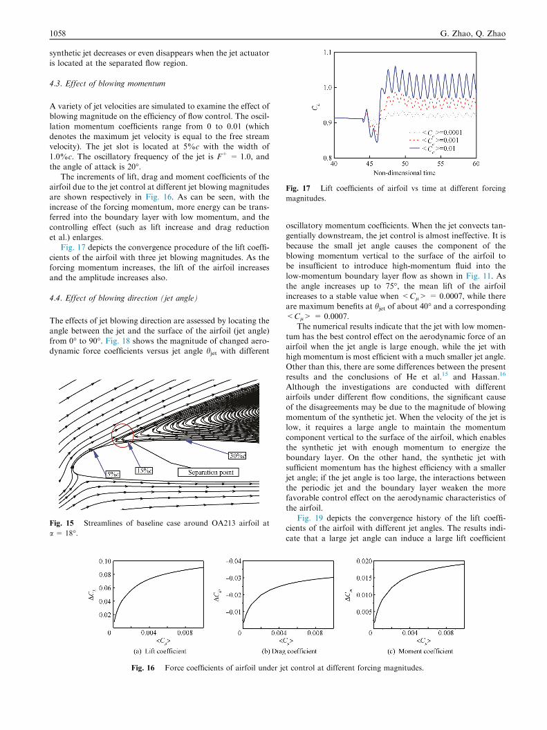
Fig. 17 Lift coefficients of airfoil vs time at different forcing
magnitudes.
1058 G. Zhao, Q. Zhao
synthetic jet decreases or even disappears when the jet actuatoris located at the separated flow region.
4.3. Effect of blowing momentum
A variety of jet velocities are simulated to examine the effect ofblowing magnitude on the efficiency of flow control. The oscil-
lation momentum coefficients range from 0 to 0.01 (whichdenotes the maximum jet velocity is equal to the free streamvelocity). The jet slot is located at 5%c with the width of
1.0%c. The oscillatory frequency of the jet is F+ = 1.0, andthe angle of attack is 20�.
The increments of lift, drag and moment coefficients of the
airfoil due to the jet control at different jet blowing magnitudesare shown respectively in Fig. 16. As can be seen, with theincrease of the forcing momentum, more energy can be trans-ferred into the boundary layer with low momentum, and the
controlling effect (such as lift increase and drag reductionet al.) enlarges.
Fig. 17 depicts the convergence procedure of the lift coeffi-
cients of the airfoil with three jet blowing magnitudes. As theforcing momentum increases, the lift of the airfoil increasesand the amplitude increases also.
4.4. Effect of blowing direction (jet angle)
The effects of jet blowing direction are assessed by locating theangle between the jet and the surface of the airfoil (jet angle)
from 0� to 90�. Fig. 18 shows the magnitude of changed aero-dynamic force coefficients versus jet angle hjet with different
Fig. 15 Streamlines of baseline case around OA213 airfoil at
a = 18�.
Fig. 16 Force coefficients of airfoil under je
oscillatory momentum coefficients. When the jet convects tan-gentially downstream, the jet control is almost ineffective. It is
because the small jet angle causes the component of theblowing momentum vertical to the surface of the airfoil tobe insufficient to introduce high-momentum fluid into the
low-momentum boundary layer flow as shown in Fig. 11. Asthe angle increases up to 75�, the mean lift of the airfoilincreases to a stable value when <Cl> = 0.0007, while there
are maximum benefits at hjet of about 40� and a corresponding<Cl> = 0.0007.
The numerical results indicate that the jet with low momen-
tum has the best control effect on the aerodynamic force of anairfoil when the jet angle is large enough, while the jet withhigh momentum is most efficient with a much smaller jet angle.Other than this, there are some differences between the present
results and the conclusions of He et al.15 and Hassan.16
Although the investigations are conducted with differentairfoils under different flow conditions, the significant cause
of the disagreements may be due to the magnitude of blowingmomentum of the synthetic jet. When the velocity of the jet islow, it requires a large angle to maintain the momentum
component vertical to the surface of the airfoil, which enablesthe synthetic jet with enough momentum to energize theboundary layer. On the other hand, the synthetic jet with
sufficient momentum has the highest efficiency with a smallerjet angle; if the jet angle is too large, the interactions betweenthe periodic jet and the boundary layer weaken the morefavorable control effect on the aerodynamic characteristics of
the airfoil.Fig. 19 depicts the convergence history of the lift coeffi-
cients of the airfoil with different jet angles. The results indi-
cate that a large jet angle can induce a large lift coefficient
t control at different forcing magnitudes.
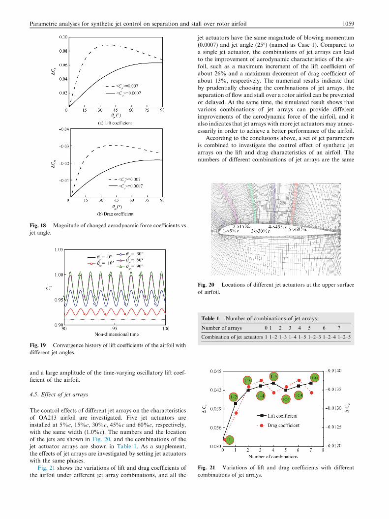
Fig. 18 Magnitude of changed aerodynamic force coefficients vs
jet angle.
Fig. 19 Convergence history of lift coefficients of the airfoil with
different jet angles.
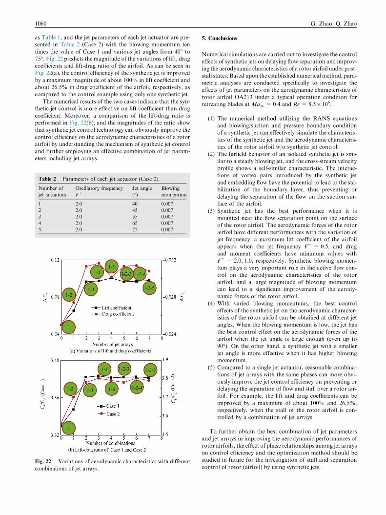
Fig. 20 Locations of different jet actuators at the upper surface
of airfoil.
Table 1 Number of combinations of jet arrays.
Number of arrays 0 1 2 3 4 5 6 7
Combination of jet actuators 1 1–2 1–3 1–4 1–5 1–2–3 1–2–4 1–2–5
Fig. 21 Variations of lift and drag coefficients with different
combinations of jet arrays.
Parametric analyses for synthetic jet control on separation and stall over rotor airfoil 1059
and a large amplitude of the time-varying oscillatory lift coef-ficient of the airfoil.
4.5. Effect of jet arrays
The control effects of different jet arrays on the characteristics
of OA213 airfoil are investigated. Five jet actuators areinstalled at 5%c, 15%c, 30%c, 45%c and 60%c, respectively,with the same width (1.0%c). The numbers and the location
of the jets are shown in Fig. 20, and the combinations of thejet actuator arrays are shown in Table 1. As a supplement,the effects of jet arrays are investigated by setting jet actuatorswith the same phases.
Fig. 21 shows the variations of lift and drag coefficients ofthe airfoil under different jet array combinations, and all the
jet actuators have the same magnitude of blowing momentum(0.0007) and jet angle (25�) (named as Case 1). Compared toa single jet actuator, the combinations of jet arrays can lead
to the improvement of aerodynamic characteristics of the air-foil, such as a maximum increment of the lift coefficient ofabout 26% and a maximum decrement of drag coefficient of
about 13%, respectively. The numerical results indicate thatby prudentially choosing the combinations of jet arrays, theseparation of flow and stall over a rotor airfoil can be prevented
or delayed. At the same time, the simulated result shows thatvarious combinations of jet arrays can provide differentimprovements of the aerodynamic force of the airfoil, and italso indicates that jet arrays with more jet actuators may unnec-
essarily in order to achieve a better performance of the airfoil.According to the conclusions above, a set of jet parameters
is combined to investigate the control effect of synthetic jet
arrays on the lift and drag characteristics of an airfoil. Thenumbers of different combinations of jet arrays are the same
1060 G. Zhao, Q. Zhao
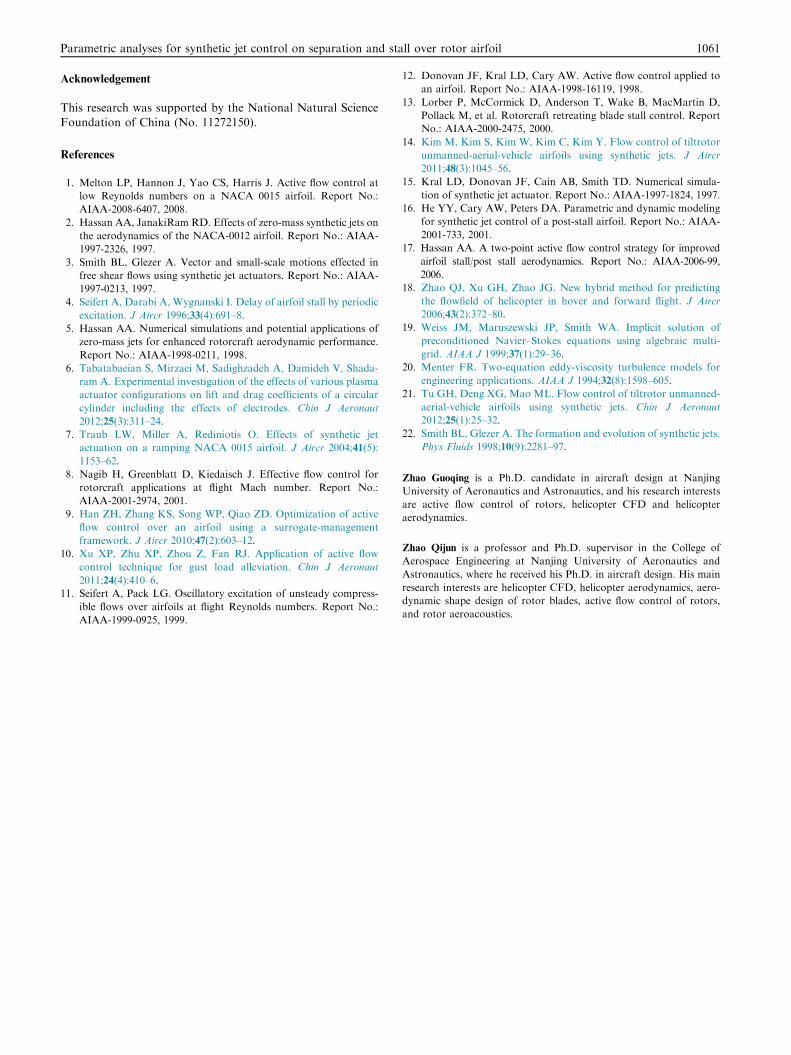
as Table 1, and the jet parameters of each jet actuator are pre-sented in Table 2 (Case 2) with the blowing momentum tentimes the value of Case 1 and various jet angles from 40� to
75�. Fig. 22 predicts the magnitude of the variations of lift, dragcoefficients and lift-drag ratio of the airfoil. As can be seen inFig. 22(a), the control efficiency of the synthetic jet is improved
by a maximum magnitude of about 100% in lift coefficient andabout 26.5% in drag coefficient of the airfoil, respectively, ascompared to the control example using only one synthetic jet.
The numerical results of the two cases indicate that the syn-thetic jet control is more effective on lift coefficient than dragcoefficient. Moreover, a comparison of the lift-drag ratio isperformed in Fig. 22(b), and the magnitudes of the ratio show
that synthetic jet control technology can obviously improve thecontrol efficiency on the aerodynamic characteristics of a rotorairfoil by understanding the mechanism of synthetic jet control
and further employing an effective combination of jet param-eters including jet arrays.
Table 2 Parameters of each jet actuator (Case 2).
Number of
jet actuators
Oscillatory frequency
F+Jet angle
(�)Blowing
momentum
1 2.0 40 0.007
2 2.0 45 0.007
3 2.0 55 0.007
4 2.0 65 0.007
5 2.0 75 0.007
Fig. 22 Variations of aerodynamic characteristics with different
combinations of jet arrays.
5. Conclusions
Numerical simulations are carried out to investigate the controleffects of synthetic jets on delaying flow separation and improv-
ing the aerodynamic characteristics of a rotor airfoil under post-stall states. Based upon the established numerical method, para-metric analyses are conducted specifically to investigate the
effects of jet parameters on the aerodynamic characteristics ofrotor airfoil OA213 under a typical operation condition forretreating blades at Ma1= 0.4 and Re = 8.5 · 106.
(1) The numerical method utilizing the RANS equationsand blowing/suction and pressure boundary conditionof a synthetic jet can effectively simulate the characteris-
tics of the synthetic jet and the aerodynamic characteris-tics of the rotor airfoil w/o synthetic jet control.
(2) The farfield behavior of an isolated synthetic jet is sim-
ilar to a steady blowing jet, and the cross-stream velocityprofile shows a self-similar characteristic. The interac-tions of vortex pairs introduced by the synthetic jet
and embedding flow have the potential to lead to the sta-bilization of the boundary layer, thus preventing ordelaying the separation of the flow on the suction sur-face of the airfoil.
(3) Synthetic jet has the best performance when it ismounted near the flow separation point on the surfaceof the rotor airfoil. The aerodynamic forces of the rotor
airfoil have different performances with the variation ofjet frequency: a maximum lift coefficient of the airfoilappears when the jet frequency F+ = 0.5, and drag
and moment coefficients have minimum values withF+ = 2.0, 1.0, respectively. Synthetic blowing momen-tum plays a very important role in the active flow con-
trol on the aerodynamic characteristics of the rotorairfoil, and a large magnitude of blowing momentumcan lead to a significant improvement of the aerody-namic forces of the rotor airfoil.
(4) With varied blowing momentums, the best controleffects of the synthetic jet on the aerodynamic character-istics of the rotor airfoil can be obtained at different jet
angles. When the blowing momentum is low, the jet hasthe best control effect on the aerodynamic forces of theairfoil when the jet angle is large enough (even up to
90�). On the other hand, a synthetic jet with a smallerjet angle is more effective when it has higher blowingmomentum.
(5) Compared to a single jet actuator, reasonable combina-
tions of jet arrays with the same phases can more obvi-ously improve the jet control efficiency on preventing ordelaying the separation of flow and stall over a rotor air-
foil. For example, the lift and drag coefficients can beimproved by a maximum of about 100% and 26.5%,respectively, when the stall of the rotor airfoil is con-
trolled by a combination of jet arrays.
To further obtain the best combination of jet parameters
and jet arrays in improving the aerodynamic performances ofrotor airfoils, the effect of phase relationships among jet arrayson control efficiency and the optimization method should bestudied in future for the investigation of stall and separation
control of rotor (airfoil) by using synthetic jets.
Parametric analyses for synthetic jet control on separation and stall over rotor airfoil 1061
Acknowledgement
This research was supported by the National Natural Science
Foundation of China (No. 11272150).
References
1. Melton LP, Hannon J, Yao CS, Harris J. Active flow control at
low Reynolds numbers on a NACA 0015 airfoil. Report No.:
AIAA-2008-6407, 2008.
2. Hassan AA, JanakiRam RD. Effects of zero-mass synthetic jets on
the aerodynamics of the NACA-0012 airfoil. Report No.: AIAA-
1997-2326, 1997.
3. Smith BL, Glezer A. Vector and small-scale motions effected in
free shear flows using synthetic jet actuators. Report No.: AIAA-
1997-0213, 1997.
4. Seifert A, Darabi A, Wygnanski I. Delay of airfoil stall by periodic
excitation. J Aircr 1996;33(4):691–8.
5. Hassan AA. Numerical simulations and potential applications of
zero-mass jets for enhanced rotorcraft aerodynamic performance.
Report No.: AIAA-1998-0211, 1998.
6. Tabatabaeian S, Mirzaei M, Sadighzadeh A, Damideh V, Shada-
ram A. Experimental investigation of the effects of various plasma
actuator configurations on lift and drag coefficients of a circular
cylinder including the effects of electrodes. Chin J Aeronaut
2012;25(3):311–24.
7. Traub LW, Miller A, Rediniotis O. Effects of synthetic jet
actuation on a ramping NACA 0015 airfoil. J Aircr 2004;41(5):
1153–62.
8. Nagib H, Greenblatt D, Kiedaisch J. Effective flow control for
rotorcraft applications at flight Mach number. Report No.:
AIAA-2001-2974, 2001.
9. Han ZH, Zhang KS, Song WP, Qiao ZD. Optimization of active
flow control over an airfoil using a surrogate-management
framework. J Aircr 2010;47(2):603–12.
10. Xu XP, Zhu XP, Zhou Z, Fan RJ. Application of active flow
control technique for gust load alleviation. Chin J Aeronaut
2011;24(4):410–6.
11. Seifert A, Pack LG. Oscillatory excitation of unsteady compress-
ible flows over airfoils at flight Reynolds numbers. Report No.:
AIAA-1999-0925, 1999.
12. Donovan JF, Kral LD, Cary AW. Active flow control applied to
an airfoil. Report No.: AIAA-1998-16119, 1998.
13. Lorber P, McCormick D, Anderson T, Wake B, MacMartin D,
Pollack M, et al. Rotorcraft retreating blade stall control. Report
No.: AIAA-2000-2475, 2000.
14. Kim M, Kim S, Kim W, Kim C, Kim Y. Flow control of tiltrotor
unmanned-aerial-vehicle airfoils using synthetic jets. J Aircr
2011;48(3):1045–56.
15. Kral LD, Donovan JF, Cain AB, Smith TD. Numerical simula-
tion of synthetic jet actuator. Report No.: AIAA-1997-1824, 1997.
16. He YY, Cary AW, Peters DA. Parametric and dynamic modeling
for synthetic jet control of a post-stall airfoil. Report No.: AIAA-
2001-733, 2001.
17. Hassan AA. A two-point active flow control strategy for improved
airfoil stall/post stall aerodynamics. Report No.: AIAA-2006-99,
2006.
18. Zhao QJ, Xu GH, Zhao JG. New hybrid method for predicting
the flowfield of helicopter in hover and forward flight. J Aircr
2006;43(2):372–80.
19. Weiss JM, Maruszewski JP, Smith WA. Implicit solution of
preconditioned Navier–Stokes equations using algebraic multi-
grid. AIAA J 1999;37(1):29–36.
20. Menter FR. Two-equation eddy-viscosity turbulence models for
engineering applications. AIAA J 1994;32(8):1598–605.
21. Tu GH, Deng XG, Mao ML. Flow control of tiltrotor unmanned-
aerial-vehicle airfoils using synthetic jets. Chin J Aeronaut
2012;25(1):25–32.
22. Smith BL, Glezer A. The formation and evolution of synthetic jets.
Phys Fluids 1998;10(9):2281–97.
Zhao Guoqing is a Ph.D. candidate in aircraft design at Nanjing
University of Aeronautics and Astronautics, and his research interests
are active flow control of rotors, helicopter CFD and helicopter
aerodynamics.
Zhao Qijun is a professor and Ph.D. supervisor in the College of
Aerospace Engineering at Nanjing University of Aeronautics and
Astronautics, where he received his Ph.D. in aircraft design. His main
research interests are helicopter CFD, helicopter aerodynamics, aero-
dynamic shape design of rotor blades, active flow control of rotors,
and rotor aeroacoustics.