Embed Size (px)
Citation preview
ENTSO-E AISBL • Avenue de Cortenbergh 100 • 1000 Brussels • Belgium • Tel + 32 2 741 09 50 • Fax + 32 2 741 09 51 • [email protected] • www. entsoe.eu
Parameters related to voltage issues
ENTSO-E guidance document for national
implementation for network codes on grid connection
16 November 2016
Parameters related to voltage issues
ENTSO-E AISBL • Avenue de Cortenbergh 100 • 1000 Brussels • Belgium • Tel + 32 2 741 09 50 • Fax + 32 2 741 09 51 • [email protected] • www. entsoe.eu
2
Table of Contents Description ...................................................................................................................................................3
Code(s) and Article(s) ..............................................................................................................................3
Introduction ..............................................................................................................................................3
NC Frame .................................................................................................................................................4
Further Info...............................................................................................................................................7
INTERDEPENDENCIES ............................................................................................................................7
Within CNCs ............................................................................................................................................7
In other NCs .............................................................................................................................................8
System Characteristics .............................................................................................................................8
Technology characteristics .......................................................................................................................8
COLLABORATION ....................................................................................................................................9
TSO – TSO ...............................................................................................................................................9
TSO – DSO ..............................................................................................................................................9
RSO – Grid User ......................................................................................................................................9
Table 1 – RfG Non-Exhaustive Requirements ...........................................................................................10
Table 2 – DCC Non-Exhaustive Requirements ..........................................................................................14
Table 3 – HVDC Non-Exhaustive Requirements ......................................................................................16
Parameters related to voltage issues
ENTSO-E AISBL • Avenue de Cortenbergh 100 • 1000 Brussels • Belgium • Tel + 32 2 741 09 50 • Fax + 32 2 741 09 51 • [email protected] • www. entsoe.eu
3
Description
Code(s) and
Article(s)
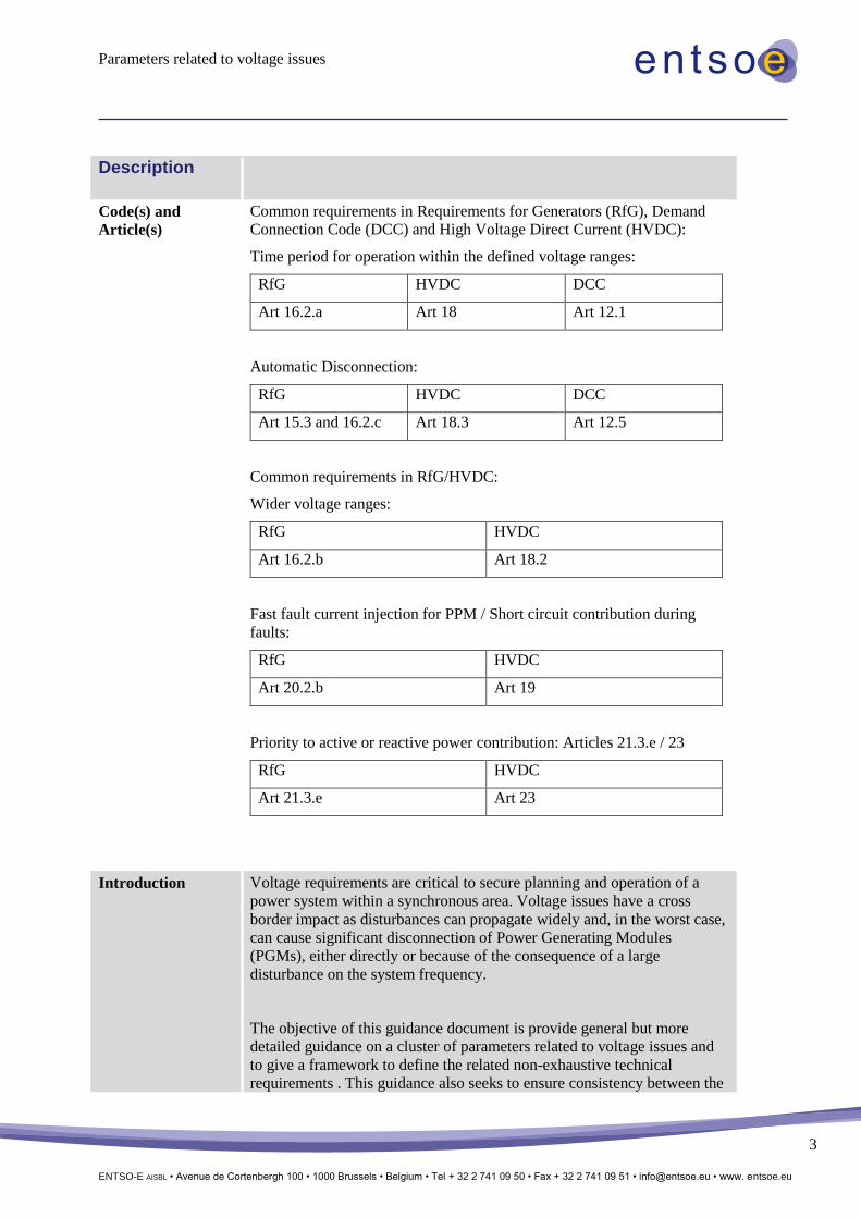
Common requirements in Requirements for Generators (RfG), Demand
Connection Code (DCC) and High Voltage Direct Current (HVDC):
Time period for operation within the defined voltage ranges:
RfG HVDC DCC
Art 16.2.a Art 18 Art 12.1
Automatic Disconnection:
RfG HVDC DCC
Art 15.3 and 16.2.c Art 18.3 Art 12.5
Common requirements in RfG/HVDC:
Wider voltage ranges:
RfG HVDC
Art 16.2.b Art 18.2
Fast fault current injection for PPM / Short circuit contribution during
faults:
RfG HVDC
Art 20.2.b Art 19
Priority to active or reactive power contribution: Articles 21.3.e / 23
RfG HVDC
Art 21.3.e Art 23
Introduction Voltage requirements are critical to secure planning and operation of a
power system within a synchronous area. Voltage issues have a cross
border impact as disturbances can propagate widely and, in the worst case,
can cause significant disconnection of Power Generating Modules
(PGMs), either directly or because of the consequence of a large
disturbance on the system frequency.
The objective of this guidance document is provide general but more
detailed guidance on a cluster of parameters related to voltage issues and
to give a framework to define the related non-exhaustive technical
requirements . This guidance also seeks to ensure consistency between the
Parameters related to voltage issues
ENTSO-E AISBL • Avenue de Cortenbergh 100 • 1000 Brussels • Belgium • Tel + 32 2 741 09 50 • Fax + 32 2 741 09 51 • [email protected] • www. entsoe.eu
4
requirements for generators, HVDC links and demand facilities in order to
ensure voltage stability or recovery.
As such this guidance document should be viewed in conjunction with the
general guidance on non-exhaustive requirements and more specific IGDs
on these issues.
This guidance document will also address the elements to be considered in
deciding whether a non-mandatory requirement shall be required by a
Transmission System Operator (TSO).
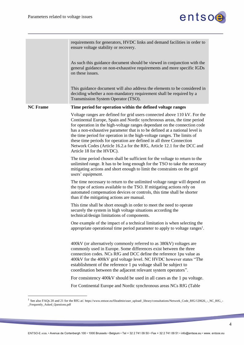
NC Frame Time period for operation within the defined voltage ranges
Voltage ranges are defined for grid users connected above 110 kV. For the
Continental Europe, Spain and Nordic synchronous areas, the time period
for operation in the high-voltage ranges dependant on the connection code
has a non-exhaustive parameter that is to be defined at a national level is
the time period for operation in the high-voltage ranges. The limits of
these time periods for operation are defined in all three Connection
Network Codes (Article 16.2.a for the RfG, Article 12.1 for the DCC and
Article 18 for the HVDC).
The time period chosen shall be sufficient for the voltage to return to the
unlimited range. It has to be long enough for the TSO to take the necessary
mitigating actions and short enough to limit the constraints on the grid
users’ equipment.
The time necessary to return to the unlimited voltage range will depend on
the type of actions available to the TSO. If mitigating actions rely on
automated compensation devices or controls, this time shall be shorter
than if the mitigating actions are manual.
This time shall be short enough in order to meet the need to operate
securely the system in high voltage situations according the
technical/design limitations of components.
One example of the impact of a technical limitation is when selecting the
appropriate operational time period parameter to apply to voltage ranges1.
400kV (or alternatively commonly referred to as 380kV) voltages are
commonly used in Europe. Some differences exist between the three
connection codes. NCs RfG and DCC define the reference 1pu value as
400kV for the 400kV grid voltage level. NC HVDC however states “The
establishment of the reference 1 pu voltage shall be subject to
coordination between the adjacent relevant system operators”.
For consistency 400kV should be used in all cases as the 1 pu voltage.
For Continental Europe and Nordic synchronous areas NCs RfG (Table
1 See also FAQs 20 and 21 for the RfG at: https://www.entsoe.eu/fileadmin/user_upload/_library/consultations/Network_Code_RfG/120626_-_NC_RfG_-
_Frequently_Asked_Questions.pdf
Parameters related to voltage issues
ENTSO-E AISBL • Avenue de Cortenbergh 100 • 1000 Brussels • Belgium • Tel + 32 2 741 09 50 • Fax + 32 2 741 09 51 • [email protected] • www. entsoe.eu
5
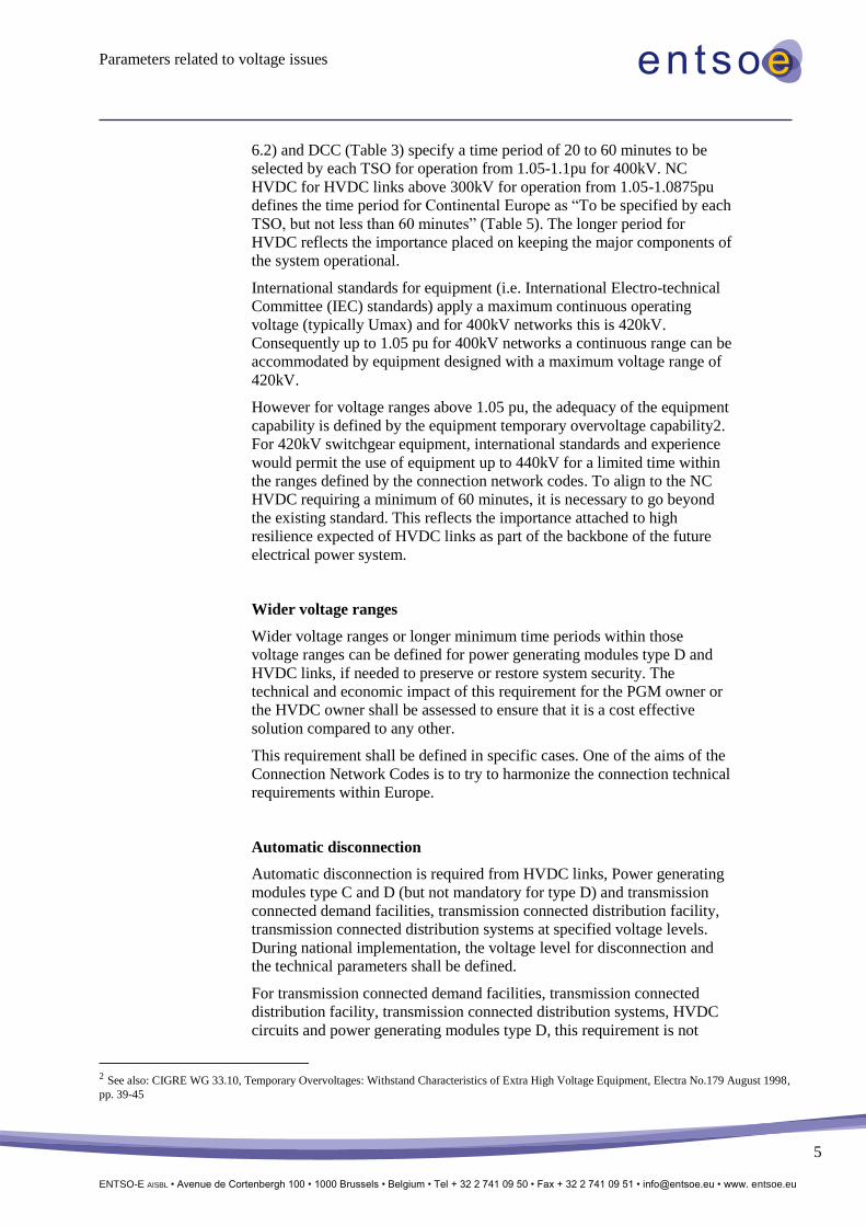
6.2) and DCC (Table 3) specify a time period of 20 to 60 minutes to be
selected by each TSO for operation from 1.05-1.1pu for 400kV. NC
HVDC for HVDC links above 300kV for operation from 1.05-1.0875pu
defines the time period for Continental Europe as “To be specified by each
TSO, but not less than 60 minutes” (Table 5). The longer period for
HVDC reflects the importance placed on keeping the major components of
the system operational.
International standards for equipment (i.e. International Electro-technical
Committee (IEC) standards) apply a maximum continuous operating
voltage (typically Umax) and for 400kV networks this is 420kV.
Consequently up to 1.05 pu for 400kV networks a continuous range can be
accommodated by equipment designed with a maximum voltage range of
420kV.
However for voltage ranges above 1.05 pu, the adequacy of the equipment
capability is defined by the equipment temporary overvoltage capability2.
For 420kV switchgear equipment, international standards and experience
would permit the use of equipment up to 440kV for a limited time within
the ranges defined by the connection network codes. To align to the NC
HVDC requiring a minimum of 60 minutes, it is necessary to go beyond
the existing standard. This reflects the importance attached to high
resilience expected of HVDC links as part of the backbone of the future
electrical power system.
Wider voltage ranges
Wider voltage ranges or longer minimum time periods within those
voltage ranges can be defined for power generating modules type D and
HVDC links, if needed to preserve or restore system security. The
technical and economic impact of this requirement for the PGM owner or
the HVDC owner shall be assessed to ensure that it is a cost effective
solution compared to any other.
This requirement shall be defined in specific cases. One of the aims of the
Connection Network Codes is to try to harmonize the connection technical
requirements within Europe.
Automatic disconnection
Automatic disconnection is required from HVDC links, Power generating
modules type C and D (but not mandatory for type D) and transmission
connected demand facilities, transmission connected distribution facility,
transmission connected distribution systems at specified voltage levels.
During national implementation, the voltage level for disconnection and
the technical parameters shall be defined.
For transmission connected demand facilities, transmission connected
distribution facility, transmission connected distribution systems, HVDC
circuits and power generating modules type D, this requirement is not
2 See also: CIGRE WG 33.10, Temporary Overvoltages: Withstand Characteristics of Extra High Voltage Equipment, Electra No.179 August 1998,
pp. 39-45
Parameters related to voltage issues
ENTSO-E AISBL • Avenue de Cortenbergh 100 • 1000 Brussels • Belgium • Tel + 32 2 741 09 50 • Fax + 32 2 741 09 51 • [email protected] • www. entsoe.eu
6
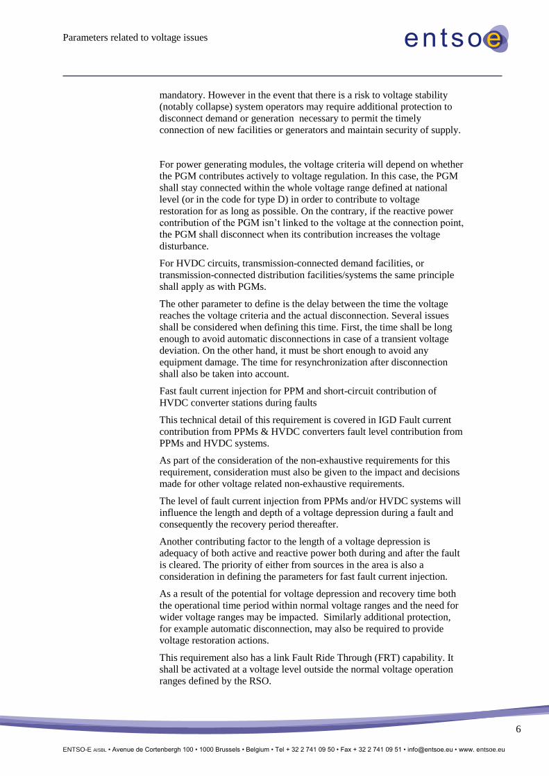
mandatory. However in the event that there is a risk to voltage stability
(notably collapse) system operators may require additional protection to
disconnect demand or generation necessary to permit the timely
connection of new facilities or generators and maintain security of supply.
For power generating modules, the voltage criteria will depend on whether
the PGM contributes actively to voltage regulation. In this case, the PGM
shall stay connected within the whole voltage range defined at national
level (or in the code for type D) in order to contribute to voltage
restoration for as long as possible. On the contrary, if the reactive power
contribution of the PGM isn’t linked to the voltage at the connection point,
the PGM shall disconnect when its contribution increases the voltage
disturbance.
For HVDC circuits, transmission-connected demand facilities, or
transmission-connected distribution facilities/systems the same principle
shall apply as with PGMs.
The other parameter to define is the delay between the time the voltage
reaches the voltage criteria and the actual disconnection. Several issues
shall be considered when defining this time. First, the time shall be long
enough to avoid automatic disconnections in case of a transient voltage
deviation. On the other hand, it must be short enough to avoid any
equipment damage. The time for resynchronization after disconnection
shall also be taken into account.
Fast fault current injection for PPM and short-circuit contribution of
HVDC converter stations during faults
This technical detail of this requirement is covered in IGD Fault current
contribution from PPMs & HVDC converters fault level contribution from
PPMs and HVDC systems.
As part of the consideration of the non-exhaustive requirements for this
requirement, consideration must also be given to the impact and decisions
made for other voltage related non-exhaustive requirements.
The level of fault current injection from PPMs and/or HVDC systems will
influence the length and depth of a voltage depression during a fault and
consequently the recovery period thereafter.
Another contributing factor to the length of a voltage depression is
adequacy of both active and reactive power both during and after the fault
is cleared. The priority of either from sources in the area is also a
consideration in defining the parameters for fast fault current injection.
As a result of the potential for voltage depression and recovery time both
the operational time period within normal voltage ranges and the need for
wider voltage ranges may be impacted. Similarly additional protection,
for example automatic disconnection, may also be required to provide
voltage restoration actions.
This requirement also has a link Fault Ride Through (FRT) capability. It
shall be activated at a voltage level outside the normal voltage operation
ranges defined by the RSO.
Parameters related to voltage issues
ENTSO-E AISBL • Avenue de Cortenbergh 100 • 1000 Brussels • Belgium • Tel + 32 2 741 09 50 • Fax + 32 2 741 09 51 • [email protected] • www. entsoe.eu
7
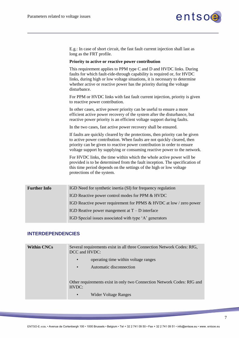
E.g.: In case of short circuit, the fast fault current injection shall last as
long as the FRT profile.
Priority to active or reactive power contribution
This requirement applies to PPM type C and D and HVDC links. During
faults for which fault-ride-through capability is required or, for HVDC
links, during high or low voltage situations, it is necessary to determine
whether active or reactive power has the priority during the voltage
disturbance.
For PPM or HVDC links with fast fault current injection, priority is given
to reactive power contribution.
In other cases, active power priority can be useful to ensure a more
efficient active power recovery of the system after the disturbance, but
reactive power priority is an efficient voltage support during faults.
In the two cases, fast active power recovery shall be ensured.
If faults are quickly cleared by the protections, then priority can be given
to active power contribution. When faults are not quickly cleared, then
priority can be given to reactive power contribution in order to ensure
voltage support by supplying or consuming reactive power to the network.
For HVDC links, the time within which the whole active power will be
provided is to be determined from the fault inception. The specification of
this time period depends on the settings of the high or low voltage
protections of the system.
Further Info IGD Need for synthetic inertia (SI) for frequency regulation
IGD Reactive power control modes for PPM & HVDC
IGD Reactive power requirement for PPMS & HVDC at low / zero power
IGD Reative power mangement at T – D interface
IGD Special issues associated with type ‘A’ generators
INTERDEPENDENCIES
Within CNCs Several requirements exist in all three Connection Network Codes: RfG,
DCC and HVDC:
• operating time within voltage ranges
• Automatic disconnection
Other requirements exist in only two Connection Network Codes: RfG and
HVDC:
• Wider Voltage Ranges
Parameters related to voltage issues
ENTSO-E AISBL • Avenue de Cortenbergh 100 • 1000 Brussels • Belgium • Tel + 32 2 741 09 50 • Fax + 32 2 741 09 51 • [email protected] • www. entsoe.eu
8
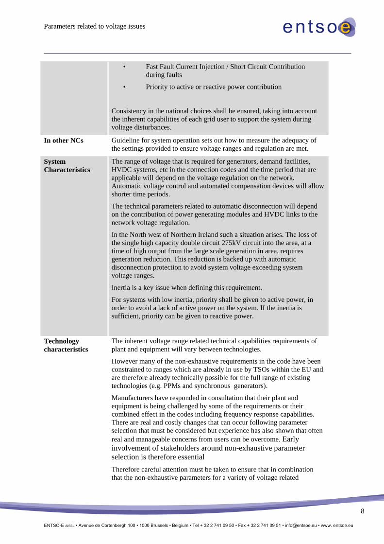
• Fast Fault Current Injection / Short Circuit Contribution
during faults
• Priority to active or reactive power contribution
Consistency in the national choices shall be ensured, taking into account
the inherent capabilities of each grid user to support the system during
voltage disturbances.
In other NCs Guideline for system operation sets out how to measure the adequacy of
the settings provided to ensure voltage ranges and regulation are met.
System
Characteristics
The range of voltage that is required for generators, demand facilities,
HVDC systems, etc in the connection codes and the time period that are
applicable will depend on the voltage regulation on the network.
Automatic voltage control and automated compensation devices will allow
shorter time periods.
The technical parameters related to automatic disconnection will depend
on the contribution of power generating modules and HVDC links to the
network voltage regulation.
In the North west of Northern Ireland such a situation arises. The loss of
the single high capacity double circuit 275kV circuit into the area, at a
time of high output from the large scale generation in area, requires
generation reduction. This reduction is backed up with automatic
disconnection protection to avoid system voltage exceeding system
voltage ranges.
Inertia is a key issue when defining this requirement.
For systems with low inertia, priority shall be given to active power, in
order to avoid a lack of active power on the system. If the inertia is
sufficient, priority can be given to reactive power.
Technology
characteristics
The inherent voltage range related technical capabilities requirements of
plant and equipment will vary between technologies.
However many of the non-exhaustive requirements in the code have been
constrained to ranges which are already in use by TSOs within the EU and
are therefore already technically possible for the full range of existing
technologies (e.g. PPMs and synchronous generators).
Manufacturers have responded in consultation that their plant and
equipment is being challenged by some of the requirements or their
combined effect in the codes including frequency response capabilities.
There are real and costly changes that can occur following parameter
selection that must be considered but experience has also shown that often
real and manageable concerns from users can be overcome. Early
involvement of stakeholders around non-exhaustive parameter
selection is therefore essential
Therefore careful attention must be taken to ensure that in combination
that the non-exhaustive parameters for a variety of voltage related
Parameters related to voltage issues
ENTSO-E AISBL • Avenue de Cortenbergh 100 • 1000 Brussels • Belgium • Tel + 32 2 741 09 50 • Fax + 32 2 741 09 51 • [email protected] • www. entsoe.eu
9
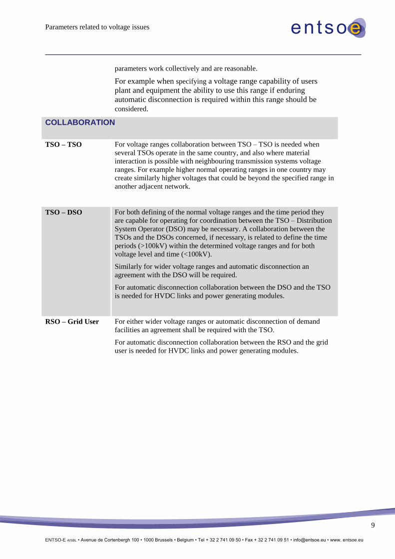
parameters work collectively and are reasonable.
For example when specifying a voltage range capability of users
plant and equipment the ability to use this range if enduring
automatic disconnection is required within this range should be
considered.
COLLABORATION
TSO – TSO For voltage ranges collaboration between TSO – TSO is needed when
several TSOs operate in the same country, and also where material
interaction is possible with neighbouring transmission systems voltage
ranges. For example higher normal operating ranges in one country may
create similarly higher voltages that could be beyond the specified range in
another adjacent network.
TSO – DSO For both defining of the normal voltage ranges and the time period they
are capable for operating for coordination between the TSO – Distribution
System Operator (DSO) may be necessary. A collaboration between the
TSOs and the DSOs concerned, if necessary, is related to define the time
periods (>100kV) within the determined voltage ranges and for both
voltage level and time (<100kV).
Similarly for wider voltage ranges and automatic disconnection an
agreement with the DSO will be required.
For automatic disconnection collaboration between the DSO and the TSO
is needed for HVDC links and power generating modules.
RSO – Grid User For either wider voltage ranges or automatic disconnection of demand
facilities an agreement shall be required with the TSO.
For automatic disconnection collaboration between the RSO and the grid
user is needed for HVDC links and power generating modules.
Parameters related to voltage issues
ENTSO-E AISBL • Avenue de Cortenbergh 100 • 1000 Brussels • Belgium • Tel + 32 2 741 09 50 • Fax + 32 2 741 09 51 • [email protected] • www. entsoe.eu
10
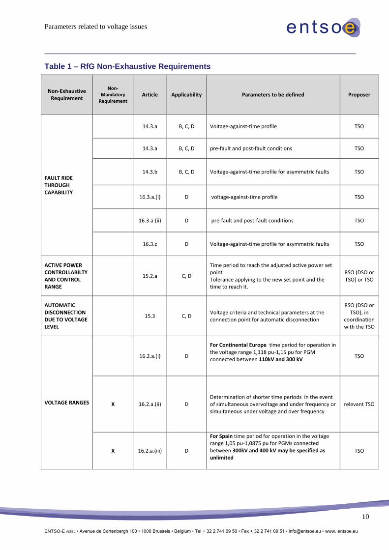
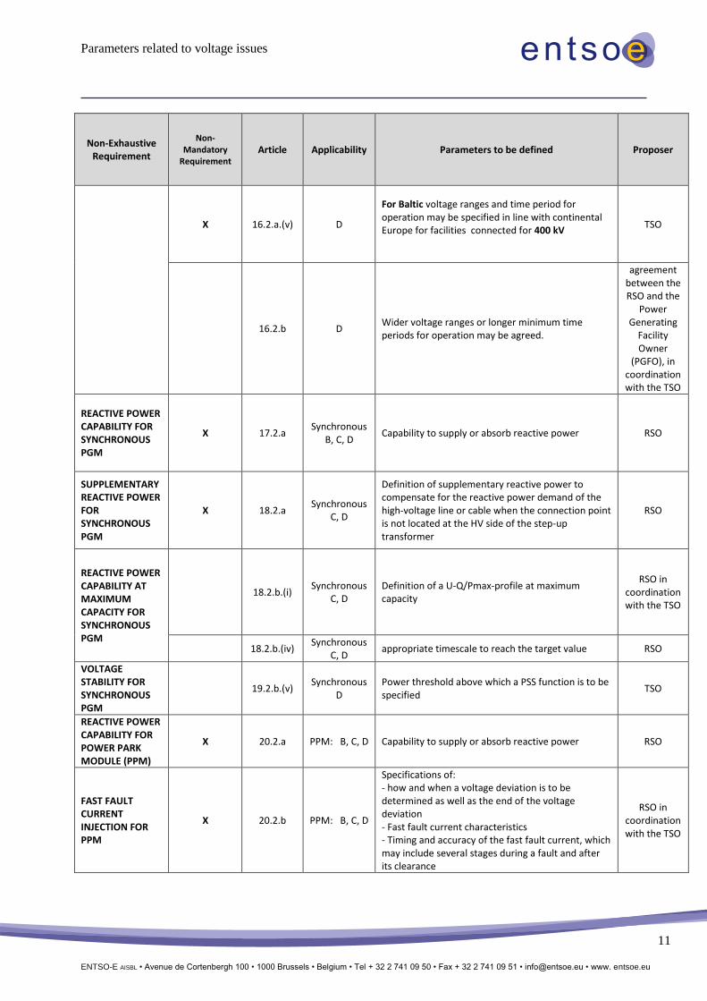
Table 1 – RfG Non-Exhaustive Requirements
Non-Exhaustive Requirement
Non-Mandatory
Requirement Article Applicability Parameters to be defined Proposer
FAULT RIDE THROUGH CAPABILITY
14.3.a B, C, D Voltage-against-time profile TSO
14.3.a B, C, D pre-fault and post-fault conditions TSO
14.3.b B, C, D Voltage-against-time profile for asymmetric faults TSO
16.3.a.(i) D voltage-against-time profile TSO
16.3.a.(ii) D pre-fault and post-fault conditions TSO
16.3.c D Voltage-against-time profile for asymmetric faults TSO
ACTIVE POWER CONTROLLABILTY AND CONTROL RANGE
15.2.a C, D
Time period to reach the adjusted active power set point Tolerance applying to the new set point and the time to reach it.
RSO (DSO or TSO) or TSO
AUTOMATIC DISCONNECTION DUE TO VOLTAGE LEVEL
15.3 C, D Voltage criteria and technical parameters at the connection point for automatic disconnection
RSO (DSO or TSO), in
coordination with the TSO
VOLTAGE RANGES
16.2.a.(i) D
For Continental Europe time period for operation in the voltage range 1,118 pu-1,15 pu for PGM connected between 110kV and 300 kV
TSO
X 16.2.a.(ii) D Determination of shorter time periods in the event of simultaneous overvoltage and under frequency or simultaneous under voltage and over frequency
relevant TSO
X 16.2.a.(iii) D
For Spain time period for operation in the voltage range 1,05 pu-1,0875 pu for PGMs connected between 300kV and 400 kV may be specified as unlimited
TSO
Parameters related to voltage issues
ENTSO-E AISBL • Avenue de Cortenbergh 100 • 1000 Brussels • Belgium • Tel + 32 2 741 09 50 • Fax + 32 2 741 09 51 • [email protected] • www. entsoe.eu
11
Non-Exhaustive Requirement
Non-Mandatory
Requirement Article Applicability Parameters to be defined Proposer
X 16.2.a.(v) D
For Baltic voltage ranges and time period for operation may be specified in line with continental Europe for facilities connected for 400 kV
TSO
16.2.b D Wider voltage ranges or longer minimum time periods for operation may be agreed.
agreement between the RSO and the
Power Generating
Facility Owner
(PGFO), in coordination with the TSO
REACTIVE POWER CAPABILITY FOR SYNCHRONOUS PGM
X 17.2.a Synchronous
B, C, D Capability to supply or absorb reactive power RSO
SUPPLEMENTARY REACTIVE POWER FOR SYNCHRONOUS PGM
X 18.2.a Synchronous
C, D
Definition of supplementary reactive power to compensate for the reactive power demand of the high-voltage line or cable when the connection point is not located at the HV side of the step-up transformer
RSO
REACTIVE POWER CAPABILITY AT MAXIMUM CAPACITY FOR SYNCHRONOUS PGM
18.2.b.(i) Synchronous
C, D Definition of a U-Q/Pmax-profile at maximum capacity
RSO in coordination with the TSO
18.2.b.(iv) Synchronous
C, D appropriate timescale to reach the target value RSO
VOLTAGE STABILITY FOR SYNCHRONOUS PGM
19.2.b.(v) Synchronous
D Power threshold above which a PSS function is to be specified
TSO
REACTIVE POWER CAPABILITY FOR POWER PARK MODULE (PPM)
X 20.2.a PPM: B, C, D Capability to supply or absorb reactive power RSO
FAST FAULT CURRENT INJECTION FOR PPM
X 20.2.b PPM: B, C, D
Specifications of: - how and when a voltage deviation is to be determined as well as the end of the voltage deviation - Fast fault current characteristics - Timing and accuracy of the fast fault current, which may include several stages during a fault and after its clearance
RSO in coordination with the TSO
Parameters related to voltage issues
ENTSO-E AISBL • Avenue de Cortenbergh 100 • 1000 Brussels • Belgium • Tel + 32 2 741 09 50 • Fax + 32 2 741 09 51 • [email protected] • www. entsoe.eu
12
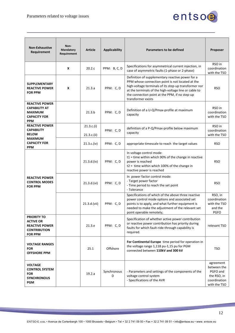
Non-Exhaustive Requirement
Non-Mandatory
Requirement Article Applicability Parameters to be defined Proposer
X 20.2.c PPM: B, C, D Specifications for asymmetrical current injection, in case of asymmetric faults (1-phase or 2-phase)
RSO in coordination with the TSO
SUPPLEMENTARY REACTIVE POWER FOR PPM
X 21.3.a PPM: C, D
Definition of supplementary reactive power for a PPM whose connection point is not located at the high-voltage terminals of its step-up transformer nor at the terminals of the high-voltage line or cable to the connection point at the PPM, if no step-up transformer exists
RSO
REACTIVE POWER CAPABILITY AT MAXIMUM CAPACITY FOR PPM
21.3.b PPM: C, D Definition of a U-Q/Pmax-profile at maximum capacity
RSO in coordination with the TSO
REACTIVE POWER CAPABILITY BELOW MAXIMUM CAPACITY FOR PPM
21.3.c.(i)
21.3.c.(ii)
PPM: C, D definition of a P-Q/Pmax-profile below maximum capacity
RSO in coordination with the TSO
21.3.c.(iv) PPM: C, D appropriate timescale to reach the target values RSO
REACTIVE POWER CONTROL MODES FOR PPM
21.3.d.(iv) PPM: C, D
In voltage control mode: t1 = time within which 90% of the change in reactive power is reached t2 = time within which 100% of the change in reactive power is reached
RSO
21.3.d.(vi) PPM: C, D
In power factor control mode: - Target power factor - Time period to reach the set point - Tolerance
RSO
21.3.d.(vii) PPM: C, D
Specifications of which of the above three reactive power control mode options and associated set points is to apply, and what further equipment is needed to make the adjustment of the relevant set point operable remotely;
RSO, in coordination with the TSO
and the PGFO
PRIORITY TO ACTIVE OR REACTIVE POWER CONTRIBUTION FOR PPM
21.3.e PPM: C, D
Specification of whether active power contribution or reactive power contribution has priority during faults for which fault-ride-through capability is required.
relevant TSO
VOLTAGE RANGES FOR OFFSHORE PPM
25.1 Offshore
For Continental Europe time period for operation in the voltage range 1,118 pu-1,15 pu for PGM connected between 110kV and 300 kV
TSO
VOLTAGE CONTROL SYSTEM FOR SYNCHRONOUS PGM
19.2.a Synchronous
D
- Parameters and settings of the components of the voltage control system - Specifications of the AVR
agreement between the
PGFO and the RSO, in
coordination with the TSO
Parameters related to voltage issues
ENTSO-E AISBL • Avenue de Cortenbergh 100 • 1000 Brussels • Belgium • Tel + 32 2 741 09 50 • Fax + 32 2 741 09 51 • [email protected] • www. entsoe.eu
13
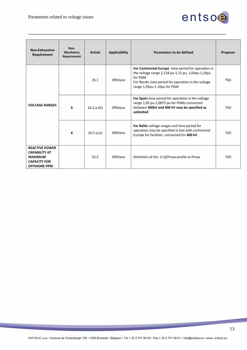
Non-Exhaustive Requirement
Non-Mandatory
Requirement Article Applicability Parameters to be defined Proposer
VOLTAGE RANGES
25.1 Offshore
For Continental Europe time period for operation in the voltage range 1,118 pu-1,15 pu, 1,05pu-1,10pu for PGM For Nordic time period for operation in the voltage range 1,05pu-1,10pu for PGM
TSO
X 16.2.a.(iii) Offshore
For Spain time period for operation in the voltage range 1,05 pu-1,0875 pu for PGMs connected between 300kV and 400 kV may be specified as unlimited
TSO
X 16.2.a.(v) Offshore
For Baltic voltage ranges and time period for operation may be specified in line with continental Europe for facilities connected for 400 kV
TSO
REACTIVE POWER CAPABILITY AT MAXIMUM CAPACITY FOR OFFSHORE PPM
25.5 Offshore Definition of the U-Q/Pmax-profile at Pmax TSO
Parameters related to voltage issues
ENTSO-E AISBL • Avenue de Cortenbergh 100 • 1000 Brussels • Belgium • Tel + 32 2 741 09 50 • Fax + 32 2 741 09 51 • [email protected] • www. entsoe.eu
14
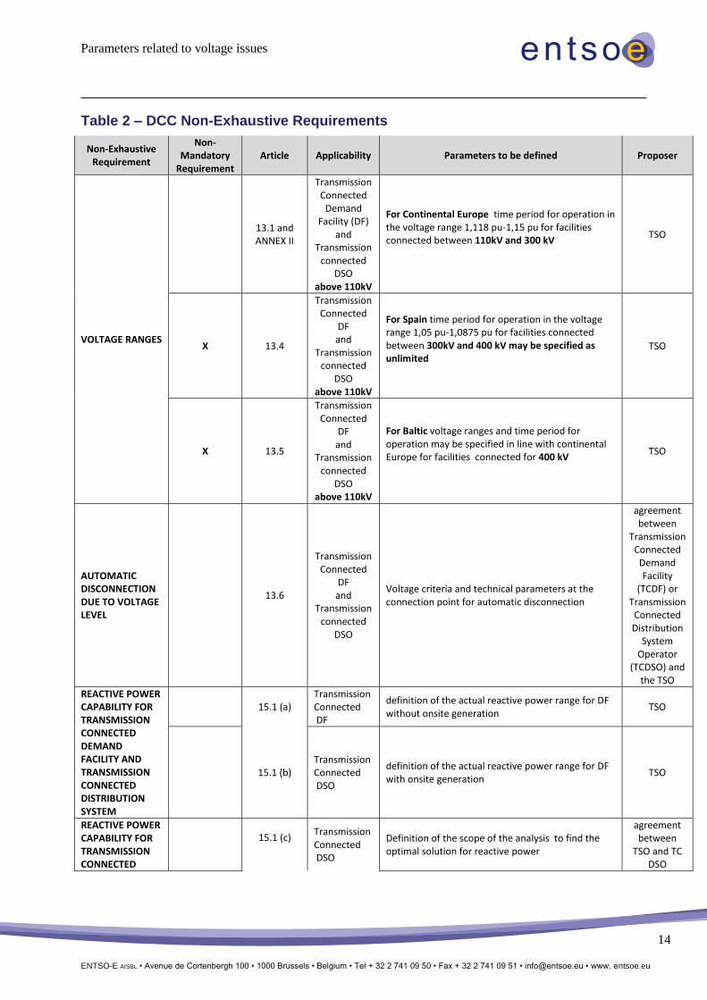
Table 2 – DCC Non-Exhaustive Requirements
Non-Exhaustive Requirement
Non-Mandatory
Requirement Article Applicability Parameters to be defined Proposer
VOLTAGE RANGES
13.1 and ANNEX II
Transmission Connected
Demand Facility (DF)
and Transmission
connected DSO
above 110kV
For Continental Europe time period for operation in the voltage range 1,118 pu-1,15 pu for facilities connected between 110kV and 300 kV
TSO
X 13.4
Transmission Connected
DF and
Transmission connected
DSO above 110kV
For Spain time period for operation in the voltage range 1,05 pu-1,0875 pu for facilities connected between 300kV and 400 kV may be specified as unlimited
TSO
X 13.5
Transmission Connected
DF and
Transmission connected
DSO above 110kV
For Baltic voltage ranges and time period for operation may be specified in line with continental Europe for facilities connected for 400 kV
TSO
AUTOMATIC DISCONNECTION DUE TO VOLTAGE LEVEL
13.6
Transmission Connected
DF and
Transmission connected
DSO
Voltage criteria and technical parameters at the connection point for automatic disconnection
agreement between
Transmission Connected
Demand Facility
(TCDF) or Transmission
Connected Distribution
System Operator
(TCDSO) and the TSO
REACTIVE POWER CAPABILITY FOR TRANSMISSION CONNECTED DEMAND FACILITY AND TRANSMISSION CONNECTED DISTRIBUTION SYSTEM
15.1 (a) Transmission Connected DF
definition of the actual reactive power range for DF without onsite generation
TSO
15.1 (b) Transmission Connected DSO
definition of the actual reactive power range for DF with onsite generation
TSO
REACTIVE POWER CAPABILITY FOR TRANSMISSION CONNECTED
15.1 (c)
Transmission Connected DSO
Definition of the scope of the analysis to find the optimal solution for reactive power
agreement between
TSO and TC DSO
Parameters related to voltage issues
ENTSO-E AISBL • Avenue de Cortenbergh 100 • 1000 Brussels • Belgium • Tel + 32 2 741 09 50 • Fax + 32 2 741 09 51 • [email protected] • www. entsoe.eu
15
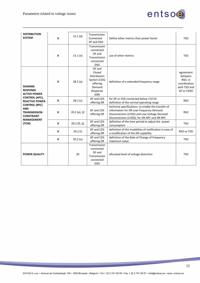
DISTRIBUTION SYSTEM X
15.1 (d) Transmission Connected DF and DSO
Define other metrics than power factor TSO
X 15.1 (e)
Transmission connected
DF and Transmission
connected DSO
use of other metrics TSO
DEMAND RESPONSE ACTIVE POWER CONTROL (APC), REACTIVE POWER CONTROL (RPC) AND TRANSMISSION CONSTRAINT MANAGEMENT (TCM)
X 28.2 (a)
DF and Closed
Distribution System (CDS)
offering Demand
Response (DR)
definition of a extended frequency range
agreement between RSO, in
coordination with TSO and DF or CDSO
X 28.2 (c) DF and CDS offering DR
for DF or CDS connected below 110 kV: definition of the normal operating range
RSO
X 20.2 (e), (l) DF and CDS offering DR
technical specifications to enable the transfer of information for DR Low Frequency Demand Disconnection (LFDD) and Low Voltage Demand Disconnection (LVDD), for DR APC and DR RPC
RSO
X 20.2 (f), (j) DF and CDS offering DR
definition of the time period to adjust the power consumption
TSO
X 20.2 (i) DF and CDS offering DR
definition of the modalities of notification in case of a modification of the DR capability
RSO or TSO
X 20.2 (o) DF and CDS offering DR
definition of the Rate of Change of Frequency maximum value
TSO
POWER QUALITY 20
Transmission connected
DF and Transmission
connected DSO
allocated level of voltage distortion TSO
Parameters related to voltage issues
ENTSO-E AISBL • Avenue de Cortenbergh 100 • 1000 Brussels • Belgium • Tel + 32 2 741 09 50 • Fax + 32 2 741 09 51 • [email protected] • www. entsoe.eu
16
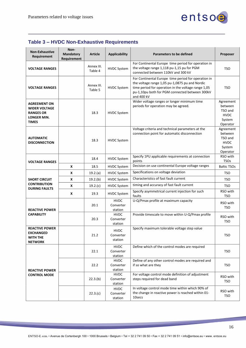
Table 3 – HVDC Non-Exhaustive Requirements
Non-Exhaustive Requirement
Non-Mandatory
Requirement Article Applicability Parameters to be defined Proposer
VOLTAGE RANGES Annex III. Table 4
HVDC System
For Continental Europe time period for operation in the voltage range 1,118 pu-1,15 pu for PGM connected between 110kV and 300 kV
TSO
VOLTAGE RANGES Annex III. Table 5
HVDC System
For Continental Europe time period for operation in the voltage range 1,05 pu-1,0875 pu and Nordic time period for operation in the voltage range 1,05 pu-1,10pu both for PGM connected between 300kV and 400 kV
TSO
AGREEMENT ON WIDER VOLTAGE RANGES OR LONGER MIN. TIMES
18.3 HVDC System
Wider voltage ranges or longer minimum time periods for operation may be agreed.
Agreement between TSO and
HVDC System
Operator
AUTOMATIC DISCONNECTION
18.3 HVDC System
Voltage criteria and technical parameters at the connection point for automatic disconnection
Agreement between TSO and
HVDC System
Operator
VOLTAGE RANGES 18.4 HVDC System
Specify 1PU applicable requirements at connection points
RSO with TSOs
X 18.5 HVDC System Decision on use continental Europe voltage ranges Baltic TSOs
SHORT CIRCUIT CONTRIBUTION DURING FAULTS
X 19.2.(a) HVDC System Specifications on voltage deviation TSO
X 19.2.(b) HVDC System Characteristics of fast fault current TSO
X 19.2.(c) HVDC System timing and accuracy of fast fault current TSO
X 19.3 HVDC System Specify asymmetrical current injection for such faults
RSO with TSO
REACTIVE POWER CAPABILITY
20.1 HVDC
Converter station
U-Q/Pmax profile at maximum capacity RSO with
TSO
20.3 HVDC
Converter station
Provide timescale to move within U-Q/Pmax profile RSO with
TSO
REACTIVE POWER EXCHANGED WITH THE NETWORK
21.2 HVDC
Converter station
Specify maximum tolerable voltage step value
TSO
REACTIVE POWER CONTROL MODE
22.1 HVDC
Converter station
Define which of the control modes are required TSO
22.2 HVDC
Converter station
Define of any other control modes are required and if so what are they TSO
22.3.(b) HVDC
Converter station
For voltage control mode definition of adjustment steps required for dead band
RSO with TSO
22.3.(c) HVDC
Converter station
In voltage control mode time within which 90% of the change in reactive power is reached within 01-10secs
RSO with TSO
Parameters related to voltage issues
ENTSO-E AISBL • Avenue de Cortenbergh 100 • 1000 Brussels • Belgium • Tel + 32 2 741 09 50 • Fax + 32 2 741 09 51 • [email protected] • www. entsoe.eu
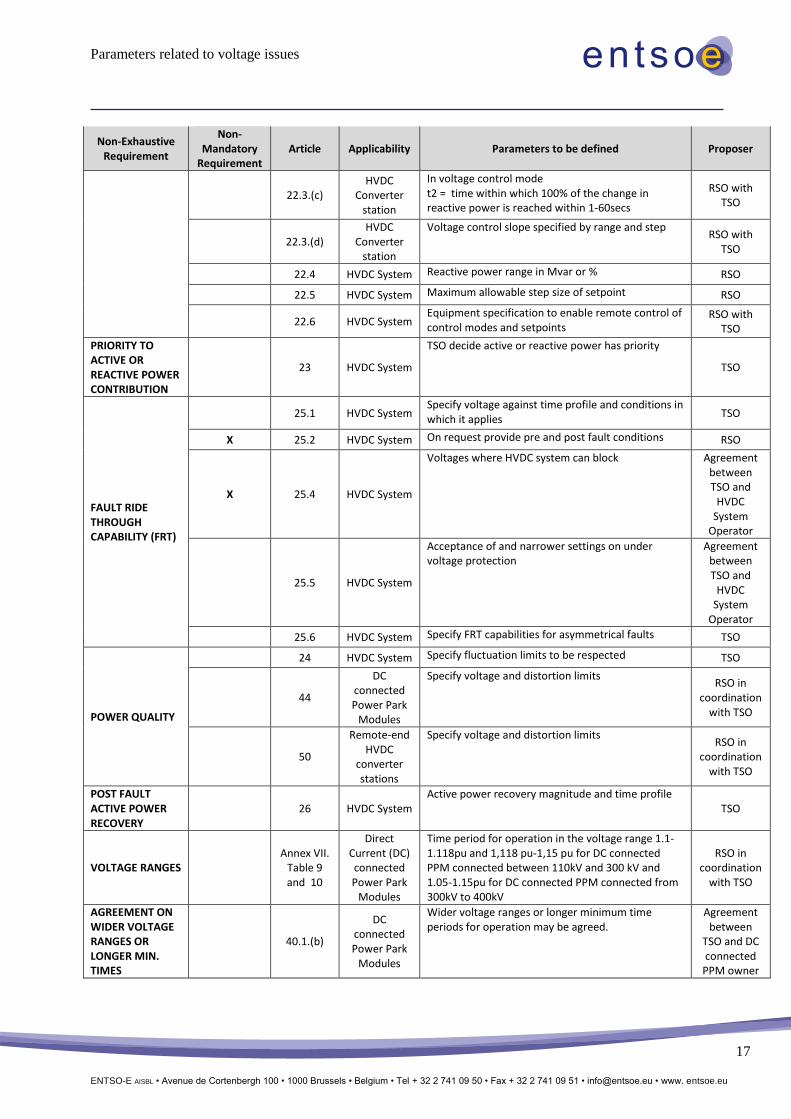
17
Non-Exhaustive Requirement
Non-Mandatory
Requirement Article Applicability Parameters to be defined Proposer
22.3.(c) HVDC
Converter station
In voltage control mode t2 = time within which 100% of the change in reactive power is reached within 1-60secs
RSO with TSO
22.3.(d) HVDC
Converter station
Voltage control slope specified by range and step RSO with
TSO
22.4 HVDC System Reactive power range in Mvar or % RSO
22.5 HVDC System Maximum allowable step size of setpoint RSO
22.6 HVDC System Equipment specification to enable remote control of control modes and setpoints
RSO with TSO
PRIORITY TO ACTIVE OR REACTIVE POWER CONTRIBUTION
23 HVDC System
TSO decide active or reactive power has priority
TSO
FAULT RIDE THROUGH CAPABILITY (FRT)
25.1 HVDC System Specify voltage against time profile and conditions in which it applies
TSO
X 25.2 HVDC System On request provide pre and post fault conditions RSO
X 25.4 HVDC System
Voltages where HVDC system can block Agreement between TSO and
HVDC System
Operator
25.5 HVDC System
Acceptance of and narrower settings on under voltage protection
Agreement between TSO and
HVDC System
Operator
25.6 HVDC System Specify FRT capabilities for asymmetrical faults TSO
POWER QUALITY
24 HVDC System Specify fluctuation limits to be respected TSO
44
DC connected Power Park
Modules
Specify voltage and distortion limits RSO in
coordination with TSO
50
Remote-end HVDC
converter stations
Specify voltage and distortion limits RSO in
coordination with TSO
POST FAULT ACTIVE POWER RECOVERY
26 HVDC System Active power recovery magnitude and time profile
TSO
VOLTAGE RANGES Annex VII.
Table 9 and 10
Direct Current (DC) connected Power Park
Modules
Time period for operation in the voltage range 1.1-1.118pu and 1,118 pu-1,15 pu for DC connected PPM connected between 110kV and 300 kV and 1.05-1.15pu for DC connected PPM connected from 300kV to 400kV
RSO in coordination
with TSO
AGREEMENT ON WIDER VOLTAGE RANGES OR LONGER MIN. TIMES
40.1.(b)
DC connected Power Park
Modules
Wider voltage ranges or longer minimum time periods for operation may be agreed.
Agreement between
TSO and DC connected
PPM owner
Parameters related to voltage issues
ENTSO-E AISBL • Avenue de Cortenbergh 100 • 1000 Brussels • Belgium • Tel + 32 2 741 09 50 • Fax + 32 2 741 09 51 • [email protected] • www. entsoe.eu
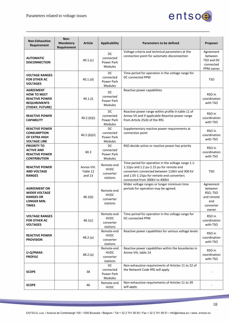
18
Non-Exhaustive Requirement
Non-Mandatory
Requirement Article Applicability Parameters to be defined Proposer
AUTOMATIC DISCONNECTION
40.1.(c)
DC connected Power Park
Modules
Voltage criteria and technical parameters at the connection point for automatic disconnection
Agreement between
TSO and DC connected
PPM owner
VOLTAGE RANGES FOR OTHER AC VOLTAGES
40.1.(d)
DC connected Power Park
Modules
Time period for operation in the voltage range for DC connected PPM
TSO
AGREEMENT HOW TO MEET REACTIVE POWER REQUIREMENTS (TODAY, FUTURE)
40.1.(i)
DC connected Power Park
Modules
Reactive power capabilities RSO in
coordination with TSO
REACTIVE POWER CAPABILITY
40.2.(b)(i)
DC connected Power Park
Modules
Reactive power range within profile in table 11 of Annex VII and if applicable Reactive power range from Article 25(4) of the RfG
RSO in coordination
with TSO
REACTIVE POWER CONSUMPTION OF EXTRA HIGH VOLTAGE LINE
40.2.(b)(ii)
DC connected Power Park
Modules
Supplementary reactive power requirements at connection point
RSO in coordination
with TSO
PRIORITY TO ACTIVE AND REACTIVE POWER CONTRIBUTION
40.3
DC connected Power Park
Modules
RSO decide active or reactive power has priority RSO in
coordination with TSO
REACTIVE POWER AND VOLTAGE RANGES
Annex VIII.
Table 12 and 13
Remote-end HVDC
converter stations
Time period for operation in the voltage range 1.1-1.12pu and 1.2 pu-1.15 pu for remote end converters connected between 110kV and 300 kV and 1.05-1.15pu for remote end converters connected from 300kV to 400kV
TSO
AGREEMENT ON WIDER VOLTAGE RANGES OR LONGER MIN. TIMES
48.1(b)
Remote-end HVDC
converter stations
Wider voltage ranges or longer minimum time periods for operation may be agreed.
Agreement between RSO, TSO
and remote end
converter owner
VOLTAGE RANGES FOR OTHER AC VOLTAGES
48.1(c)
Remote-end HVDC
converter stations
Time period for operation in the voltage range for DC connected PPM
RSO in coordination
with TSO
REACTIVE POWER PROVISION
48.2.(a)
Remote-end HVDC
converter stations
Reactive power capabilities for various voltage levels RSO in
coordination with TSO
U-Q/PMAX-PROFILE
48.2.(a)
Remote-end HVDC
converter stations
Reactive power capabilities within the boundaries in Annex VIII, table 14
RSO in coordination
with TSO
SCOPE 38
DC connected Power Park
Modules
Non-exhaustive requirements of Articles 11 to 22 of the Network Code RfG will apply
-
SCOPE 46 Remote-end
HVDC
Non-exhaustive requirements of Articles 11 to 39 will apply
-
Parameters related to voltage issues
ENTSO-E AISBL • Avenue de Cortenbergh 100 • 1000 Brussels • Belgium • Tel + 32 2 741 09 50 • Fax + 32 2 741 09 51 • [email protected] • www. entsoe.eu
19
Non-Exhaustive Requirement
Non-Mandatory
Requirement Article Applicability Parameters to be defined Proposer
converter stations


![Fault current contribution from PPMS & HVDC codes documents/NC RfG... · Generation, Volume 9, Issue 1, January 2015 [7] Erlich, I., et al: ”Dynamic behavior of offshore wind farms](https://img.pdfslide.us/doc/110x75/5c5bf88209d3f245368cb03b/fault-current-contribution-from-ppms-hvdc-codes-documentsnc-rfg-generation.jpg)