Embed Size (px)
Citation preview

1
VGB / EURELECTRIC’s generators RfG Network Code:
Needs, Feasibility, Alternative Solutions and Costs
The European Commission has tasked a consortium of DNV KEMA and COWI to perform an impact assessment of the provisions contained in the Network Code on Requirements for Grid Connection Applicable to all Generators (RfG), which will investigate:
‐ the need to implement the envisaged requirements, ‐ the technical feasibility of the requirements, ‐ the costs and benefits associated with the implementation of the requirements applicable to
generators as well as the alternative solutions when considering the proposed requirements.
VGB / EURELECTRIC’s generators (referred to as EURELECTRIC thereinafter) propose to discuss and to analyse some crucial (selected) NC RfG requirements and validate them against the criteria enumerated above:
1. Needs 2. Feasibility 3. Alternative solutions 4. Costs

2
Contents
I. Needs, Feasibility, Alternative Solutions and Costs .................................................................................. 3
Needs ............................................................................................................................................................. 3
Technical Feasibility ....................................................................................................................................... 3
Alternative Solutions ..................................................................................................................................... 3
Costs .............................................................................................................................................................. 4
II. Requirements ............................................................................................................................................ 4
Frequency ranges .......................................................................................................................................... 4
Reactive Power Ranges ................................................................................................................................. 6
Voltage ranges ............................................................................................................................................... 9
Fault Ride Through ...................................................................................................................................... 12
Power by falling frequency .......................................................................................................................... 15
Information exchange ................................................................................................................................. 16
Fault Recording Device ................................................................................................................................ 16
Injection of Reactive Current by PPM at Fault ............................................................................................ 17
Changes to, Modernization of or Replacement of Equipment.................................................................... 18
Categorisation ............................................................................................................................................. 19
Retroactivity ................................................................................................................................................ 20
Legal issues .................................................................................................................................................. 21
Missing requirements .................................................................................................................................. 21
Conclusions .................................................................................................................................................. 22

3
I. Needs, Feasibility, Alternative Solutions and Costs
Needs
In VGB / EURELECTRIC’s opinion, the term of reference’s criterion “need to implement the envisaged requirements” must be assessed under the following criteria:
The relevance of the selected requirements,
The allocation of these requirements to the generator categories,
The adequacy of the requirements regarding the system security and cross border trade issues,
The quality of the definition of the requirements (whether a capability is required or a specific solutions is prescribed),
The benefit of implementing new or deviating requirements and finally,
The appropriateness of the process (Article 4) proposed by ENTSO‐E to implement requirements at national level.
Technical Feasibility
In VGB / EURELECTRIC’s opinion, the term of reference’s criterion “technical feasibility” covers not only the pure technical feasibility in terms of physics, design, construction and qualification, but must also consider the following:
Possible interpretations of the provisions: Is the interpretation unambiguous when defining technical specifications?
The way the provisions are implemented: Is it both possible and straightforward to implement the provision?
And the consistency of the provisions: Are several implemented provisions simultaneously compatible? Note that the coherence with other EU network codes is difficult to ascertain as those codes are currently available only in a draft version.
EU network codes should NOT:
Contain requirements which are not technically feasible
Favour national codes to embark requirements which are not easy to implement
Contain wordings generating confusion and further technical debate when defining and
implementing national provisions.
Alternative Solutions
In VGB / EURELECTRIC’s opinion, “Alternative Solutions” shall be considered at requirement level, as far as
the whole process strategy for the development has been endorsed and validated by the EC. VGB /

4
EURELECTRIC’s analysis on this area targets alternative options when considering requirements, when
choosing non‐exhaustive parameters or when allocating duties, e.g. between TSOs and generators.
Costs
VGB / EURELECTRIC will not issue any estimates as to the cost of implementation of the code, due to its status still being unclear in some areas and thus leaving room for interpretation.
It will be difficult to assess the cost impact on existing PGFs, if the exact frame conditions of applying the code are not known. The question on how to proceed if the implementation of the requirements is technically not feasible for existing PGF calls for a clear answer.
Nevertheless, VGB / EURELECTRIC will elaborate on how and to which degree costs accrued to PGF systems and components are impacted by some of the RfG requirements.
II. Requirements
Frequency ranges
Needs and Feasibility
RANGE FOR UNLIMITED TIME PERIOD FOR OPERATION
The draft Network Code on Requirements for Grid Connection applicable to all Generators (RfG) proposes a continuous operating range of frequency in continental Europe area doubled in size to 49Hz – 51Hz instead of the current range (49.5Hz – 50.5Hz). In ENTSO‐E’s justification FAQ 19, it is stated that significant frequency deviations ‘may’ occur with the increased penetration of renewables. This statement is effectively contradicted by the ENTSO‐E’s requirements in the Load Frequency Control and Reserve code (LFC&R) where the clauses describe the standard that they must meet in terms of delivering frequency quality.
The draft LFC&R code keeps unchanged the maximum quasi‐steady‐state frequency deviation of 200 mHz and the normal operating range of 50 Hz +/‐ 50 mHz for Continental Europe. The LFC&R code specifies two further frequency range parameters ‐ the ‘Frequency range within time to recover frequency’ and the ‘Frequency range within time to restore frequency’. The values currently proposed for those parameters are +/‐500 mHz. This range is the current continuous operating range.
The TSOs undertook in the LFC &R code to bring the frequency back in those ranges within the ‘Time to recover frequency’ of 1 minute (UK system) and a ‘Time to restore frequency’ of at most 20 minutes (IR system). With the time and frequency criteria in the LFC&R code, there is no need to require generators to have the capability to operate continuously in a range double that of the frequency range within time to recover frequency or restore frequency.
No additional benefits are identified by requiring this new range. There is no in‐depth justification of the new requirement. Most importantly, any costs associated with such requirements are stranded since the wider range is not required by the TSO under their own criteria.

5
VGB / EURELECTRIC:
‐ have not identified any benefit of doubling the unlimited frequency range in continental Europe area and do not see any appropriate justification for such doubling,
‐ consider generators will be much more stressed and aged if the frequency quality will get worse and will create superfluous costs,
‐ call for alternative solutions to be adequately assessed.
RANGES FOR LIMITED TIME PERIOD FOR OPERATION
The need for ranges covering limited time period comes from the fact that generators cannot be designed to stay connected to the grid regardless of the frequency. Therefore, it is necessary to find out an agreement between generators and TSOs to get the assurance that generators will stay connected during the time period when the frequency is out of the range covering the unlimited time. This agreement shall contain not only the ranges of limited time period for operation, but also the durations and the rate of occurrences. The ranges and the durations give TSOs the conditions and the time to launch corrective measures (activation of manual reserves, load shedding, etc.). The rate of occurrences protects generators against too many abnormal frequency situations which markedly stress generators and may cause severe simultaneous damages on plant equipments.
VGB / EURELECTRIC consider the definition of the needs for limited time period incomplete. The 30 minute minimum duration goes much beyond existing requirements1 in most continental European countries and has not been justified. The durations have been set unilaterally and rate of occurrences is missing.
Alternative Solutions
ENTSO‐E's solution (wider frequency ranges) anticipates a possible degradation of the frequency but does not really solve the problem as it does not address the root causes of frequency deviations ‐ a reduction in system inertia, a limited knowledge of the behaviour of dispatched renewable energy sources and the dispatch of generating units in the electricity market which ignores ramping. The TSOs have not proposed solutions addressing the issues of system inertia and ramping although some work has been published in Ireland on this very matter (http://www.eirgrid.com/media/System_Services_Consultation_Products.pdf). It is clear that alternative solutions exist and should be assessed.
Besides, the conclusion of an ENTSO‐E ad‐hoc team investigating the deterministic frequency deviation found that there is no need for a wider frequency range (ENTSO‐E/EURELECTRIC Deterministic frequency deviations – root causes and proposals for potential solutions2).
According to the current practices (UCTE handbook “Emergency Operations Policy 5”, page 8), load‐shedding has to be executed at frequencies in the range between 49.0 Hz and 48.0 Hz with delays of max 350 ms. VGB / EURELECTRIC do not understand the need to impose a minimum time period of 30 minutes for operation at abnormal frequencies if current practices impose a max delay of 350 ms. Due to the fact that, according to the current rules, every TSO has to right to define also additional actions for under‐frequency load shedding, VGB / EURELECTRIC propose to define the time duration for operation at abnormal frequencies at national level according Art. 4. This proposal favours the integration of national emergency plan without over specifications.
1 For instance, the National grid for the commissioning test in 2011 at WB (UK) plant has limited the duration at 48Hz to 32 s. The code requests .. 90 minutes ! 2 http://www.eurelectric.org/media/26970/frequency_deviations_final_february_2012‐2012‐030‐0186‐01‐e.pdf

6
It is also the intention to develop an “Emergency Code”3 in the near future. It is meaningless to stipulate at this moment Power Generation Modules (PGM) specifications for emergency situations if operational provisions for emergency procedures will be agreed later.
Costs
These requirements address the ability of electrical systems to withstand the ranges and the durations requested, particularly for auxiliary and safety systems.
‐ For nuclear units, safety cases have to be re‐analysed and new licensing studies have to be developed. The extra costs for existing equipments or for new build may be significant if qualification processes have to be upgraded (primary pumps, feed‐water and condensate pumps.). Please refer to the WENRA letter attached for further info.
‐ For hydro units, safety analysis may reveal excessive costs for civil engineering to implement infrastructures hosting compliant equipments (for transformers for instance).
The strongest criterion representing the quality of the frequency, the standard deviation, has been removed from the draft LFC&R Network Code, revealing the objective to allow the degradation of the frequency quality. In widening the frequency standard deviation and the unlimited operating range, VGB / EURELECTRIC expect that the time generators will be operating outside their governor deadband will increase by 30%. Increasing the service of units delivering frequency response will have significant impacts on the lifetime of the governor and turbine components. This can be seen when examining the criteria from Turbine manufacturers for Equivalent Operating Hours.
Further costs must be allotted to the risks associated with the degradation of the frequency:
‐ Risk of common failure modes on existing generators not designed for operation within extended limited frequency ranges. This risk is present on the whole synchronous area due to the standardisation of equipments by the manufacturers on that area.
‐ Risk on security of supply by having long generator outages due to damaged components with high repair/exchange durations (e.g. 18 months for delivery and replacement of turbine blades).
Reactive Power Ranges
Needs and Feasibility
VGB / EURELECTRIC recognize the need for TSOs to request a minimum reactive power capability, giving TSOs the ability to control the voltage in normal situations at the grid connection point. Reactive power is needed to energize the electrical grid and it is logical that power plants generate the variable basic need of reactive power for the grid with a range up to 0.4 rated power. However, it is not logical to prescribe extremely wide ranges as imposed in the RfG network code because cheaper alternatives may exist.
The maximum reactive range requirement proposed by ENTSO‐E during the public consultation got 144 comments posted by stakeholders only on chapter “Type C Synchronous Generating Units shall fulfil the following requirements referring to voltage stability” and the terms “not realistic” is used 21 times in the
3 http://ec.europa.eu/energy/gas_electricity/codes/codes_en.htm mentions a “NC on requirements and operational procedures in emergency” but without delivery date.

7
comments. VGB / EURELECTRIC note that ENTSO‐E has not expressed maximum TSOs needs in a reasonable, comprehensive and clear manner, particularly when considering the binding character of the code. It is clear, that each TSO will have to make its choice out of the envelope being defined by the requirement. However, it is not reasonable to define a maximum range which is technically not feasible.
The choices made by ENTSO‐E to set this requirement using a (V,Q/Pmax) square4 profile and oversized ranges5 for V and Q/Pmax give rise to the following concerns :
‐ The code does not clarify whether the proposed ranges would fit the future needs of the electrical system and whether this capability will be adequate.
‐ The possibility for TSOs to define reactive capability needs using different shapes (squares or parallelograms) will generate competition distortion because the basic needs have not been defined and harmonized.
‐ Art. 13 Table 8: The choice of maximum Q/Pmax values has not been justified and is not aligned with
existing practices in Continental EU (0.5 to 0.75). All power plant experts consider ENTSO‐E’s proposal
for Q/Pmax (0.95) for Continental Europe as too high, leading to extremely onerous costs for
generators. The maximum range of the steady state voltage should be aligned with the unlimited
voltage range. As example, following the comparison between ENTSO‐E desires and the reality in
France:
Comparison of U/Q diagrams at generator voltage terminals “CST alternateur EDF” means standard EDF’s specification for generators
Unclear/ non consistency of combined provisions:
4 Continuous operation with higher voltages / higher current due to reactive power production shortens the life time of the machine. Higher currents also cause higher losses. It is therefore in the interests of the generating unit operator to deliberately limit the reactive power capability. There should at least be provision to compensate the generating unit operator for the additional investment and operating costs if the limits are to be expanded 5 For example, the range for Q/Pmax is far too large for continental Europe in relation to current practices (ENTSOE requests 0.95 where it is only 0.67 in France or 0.74 in Germany). All voltage ranges may vary only in a range of ‐10% till +10% according to EN 50160. Also according to the ENTSO‐E FAQ 20 the limits have to be ‐10% and +10%.
0,80
0,85
0,90
0,95
1,00
1,05
1,10
1,15
1,20
‐0,65 ‐0,45 ‐0,25 ‐0,05 0,15 0,35 0,55 0,75
points RTE décret 2008
données EUR rev.C 2001
ENTSOe fixed outer envelope
ENTSOe max profile envelope in the fixed outer envelope
CST alternateur EDF
DIAGRAMME U/Q ALTERNATEUR
Qalt/Snalt
Ualt/Unalt

8
‐ The outer envelope in Figure 7 in the RfG code describes the capability for a PGF to supply active and reactive power in a maximum voltage range of 0.875 pu to 1.1 pu. The real voltage range is narrower and may not exceed the inner envelop with a maximum voltage range of 0.225 pu.
‐ Table 6.1 imposes that all PGF remain connected to the grid for a voltage range of 0.85 pu to 1.15 pu. So at a voltage level between 0.850 pu to 0.875 pu (or more) and between 1.10 pu (or less) to 1.15 pu, a PGF must remain connected to the grid without requesting reactive power capability.
The combination of both provisions prompts the need to make investments without any potential to benefit from it, in other words, this entails a waste of money.
VGB / EURELECTRIC recommend making Art. 11 coherent with Art. 13 by imposing in Art. 11 a voltage range identical to the inner envelope according to Art. 13.
Alternative and costs
Larger reactive power ranges than those commonly admitted by the industry shall be justified by TSOs and the decision to request larger ranges should be based according a payment process (usage /capacity) delivering the best benefit for the community. Grid solutions like static VAR compensator, capacitor banks or phase‐shifters should be analysed where local needs request larger reactive power capabilities.
Reactive power can be injected by a generating unit or by capacitor banks installed in the grid. Not only the installation costs are different, but also the availability, the reliability and the grid location are to be taken into account for the Cost Benefit Analysis.
The cost of additional MVAr capacity should be compared between:
The cost for the generator:
An alternator with an extra capacity
A step‐up transformer with an extra capacity
An energizing system
The cost for a capacitor bank:
A capacitor bank (without filters6)
Installation cost
HV bay
These requirements impact the size and the weight of the generators, including their cooling and monitoring systems. Energizing systems shall be oversized.
Theoretically, it is possible to get generators compliant with the fixed outer envelope. However, to date there is no existing factory in the world large enough and able to manufacture a 2000 MVA generator compliant with ENTSO‐E fixed outer envelope.
Availability consideration: The voltage control system must always be available. A capacitor bank is always available (at exception of maintenance: 1 day / 3 years). A generating unit supplying the same reactive power can be out of service due to an internal defect or due to market conditions. At the current power market conditions, a CCGT power plant can deliver reactive power only 1000 hours/year which has to be compared with a capacitor bank which is available 8000 hours/year.
6 The cost of a filter is defined by the measured harmonic distortion and depends on the location in the HV grid.

9
The grid operator can define an optimal place in the grid to install a capacitor bank, depending only from grid “reactive power” characteristics. The localization of a generating unit is done by an external party without any impact of the grid characteristics for reactive power management.
VGB / EURELECTRIC propose the following reactive power capability as a minimum requirement (red envelope) included in a maximum standard requirement (green envelope). If TSO’s needs are larger at a specific location, then a CBA should shed light on where would be the best choice to implement the extra reactive power capability.
Diagram proposed by VGB / EURELECTRIC during the public consultation of the RfG code.
Voltage ranges
Needs
Voltage is a varying parameter in electrical grids. In many countries the voltage in the HV grids varies in ranges of ‐7.5% to + 7.5% and this range is much smaller than the range imposed by the RfG network code.
The needs expressed by ENTSO‐E for the voltage between 110kV and 300 kV have dramatically increased between the public consultation and the final draft:
Voltage Ranges 110kV and 300 kV grids
Public Consultation Final Draft
0.80 pu – 0.85 pu 30 min N.A.
0.85 pu – 0.90 pu 60 min 60 min
10
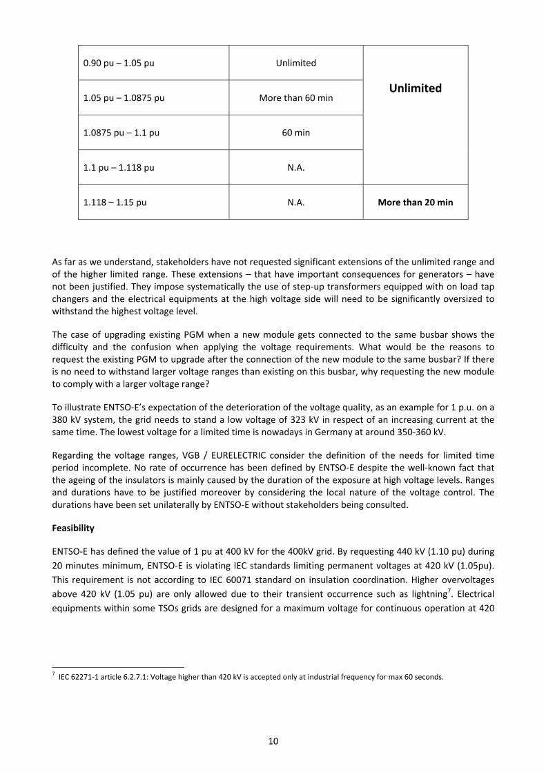
0.90 pu – 1.05 pu Unlimited
Unlimited 1.05 pu – 1.0875 pu More than 60 min
1.0875 pu – 1.1 pu 60 min
1.1 pu – 1.118 pu N.A.
1.118 – 1.15 pu N.A. More than 20 min
As far as we understand, stakeholders have not requested significant extensions of the unlimited range and of the higher limited range. These extensions – that have important consequences for generators – have not been justified. They impose systematically the use of step‐up transformers equipped with on load tap changers and the electrical equipments at the high voltage side will need to be significantly oversized to withstand the highest voltage level.
The case of upgrading existing PGM when a new module gets connected to the same busbar shows the difficulty and the confusion when applying the voltage requirements. What would be the reasons to request the existing PGM to upgrade after the connection of the new module to the same busbar? If there is no need to withstand larger voltage ranges than existing on this busbar, why requesting the new module to comply with a larger voltage range?
To illustrate ENTSO‐E’s expectation of the deterioration of the voltage quality, as an example for 1 p.u. on a 380 kV system, the grid needs to stand a low voltage of 323 kV in respect of an increasing current at the same time. The lowest voltage for a limited time is nowadays in Germany at around 350‐360 kV.
Regarding the voltage ranges, VGB / EURELECTRIC consider the definition of the needs for limited time period incomplete. No rate of occurrence has been defined by ENTSO‐E despite the well‐known fact that the ageing of the insulators is mainly caused by the duration of the exposure at high voltage levels. Ranges and durations have to be justified moreover by considering the local nature of the voltage control. The durations have been set unilaterally by ENTSO‐E without stakeholders being consulted.
Feasibility
ENTSO‐E has defined the value of 1 pu at 400 kV for the 400kV grid. By requesting 440 kV (1.10 pu) during
20 minutes minimum, ENTSO‐E is violating IEC standards limiting permanent voltages at 420 kV (1.05pu).
This requirement is not according to IEC 60071 standard on insulation coordination. Higher overvoltages
above 420 kV (1.05 pu) are only allowed due to their transient occurrence such as lightning7. Electrical
equipments within some TSOs grids are designed for a maximum voltage for continuous operation at 420
7 IEC 62271‐1 article 6.2.7.1: Voltage higher than 420 kV is accepted only at industrial frequency for max 60 seconds.

11
kV. VGB / EURELECTRIC do not accept requirements for power plant operators that are not accepted by
TSOs8.
It is impossible to operate PGM at low frequency and high voltage simultaneously due to excessive
magnetic flux in generators, motors and transformers according to IEC 600349.
For Continental Europe, the RfG network code imposes a voltage range of 0.85 pu to 1.15 pu for 110kV to 300 kV grids and 0.85 pu to 1.10 pu for 300kV to 400 kV grids. This range is only achievable with “on‐load‐tap‐changers” (OLTC) on step‐up transformers. The additional cost of such OLTC is minimal in the total cost of a power plant. However the impact on plant reliability is huge. A survey made by CIGRÉ was published in Electra 88_1. Below, the title and the conclusion are visualized: 41 % of all failures at step‐up transformers are due to the OLTC.
Both requirements have not been adequately justified nor has it been shown that this may be in line with existing practices although it is conflicting with IEC standards.
Alternative Solutions
As general provision, VGB / EURELECTRIC propose to limit voltage ranges to ranges currently in practice in several countries so that an OLTC is not needed. Only for very specific locations where the network is weak, wider voltage ranges are acceptable.
VGB / EURELECTRIC demand to respect always the relevant IEC standards regarding the upper voltage limit.
8 For instance, RTE (France’s TSO) uses 420kV as standard for the highest voltage for overheadlines IEC 60060‐1 (“Tension la plus élevée entre phases pour le matériel (kV valeur efficace)” in Fehler! Verweisquelle konnte nicht gefunden werden. Fehler! Verweisquelle konnte nicht gefunden werden. Fehler! Verweisquelle konnte nicht gefunden werden..
9 For example, in Switzerland at Beznau generators ABB/ALSTOM specifications request BS/BN = U/UN x fN/f < = 1.1
12
VGB / EURELECTRIC recommend also making the tables 6.1 and 6.2 in Art. 11 coherent with the voltage range imposed by the inner envelope according to Art. 13.
Costs
The main equipments concerned are the step‐up transformer, the auxiliary transformer and the high voltage equipments in the bay at the power station. For existing plants it needs to be taken into account that it is highly possible that the transformers are getting bigger that the foundation works and adjustments need to be respected as well. Furthermore extra costs will pile up as spare parts already purchased and stored for future use will become unusable.
OLTC are necessary to achieve the voltage ranges imposed by ENTOS‐E. OLTC have a huge impact on the reliability of the step‐up transformer and should be avoided in strong grids. The time to repair can take till 12 months. The total availability of the generating unit will decrease, thus influencing security of supply.
Fault Ride Through
Faults occurring on the network, within Power Generating Facilities (PGFs) or within consumer installations,
can impact the security of the wider power system. To guarantee the secure operation of the system even
in case of faults, measures are necessary to reduce the effects of those faults on the power supply system.
These measures fall on both the Network Operators and the Power Generating Facilities owners.
Requirements in the Network Code should have the objective to minimize the consequences of occurring
faults in an economically and technically optimised manner for all involved stakeholders.
The expected performance of PGMs during faults resulting in deep voltage dips due to a short circuit in the
network is handled in the fault ride through requirements in the draft network code.
During the time needed for the network protection to identify and clear a short circuit, the local network
voltage will collapse and the PGM will not be able to deliver its electrical power onto the network. The
turbine of the PGM still delivers a constant mechanical power to the shaft of the generator and the
resulting imbalance between input and output power causes a fast acceleration of the rotating parts of
turbine and generator. This acceleration is only stopped by the timely removal of the short circuit. If the
time taken for removal of the short circuit is too long, the acceleration will result in the loss of synchronism
of the PGM and tripping of the PGM becomes necessary. This maximum time is known as the ‘critical
clearance time’ (CCT).
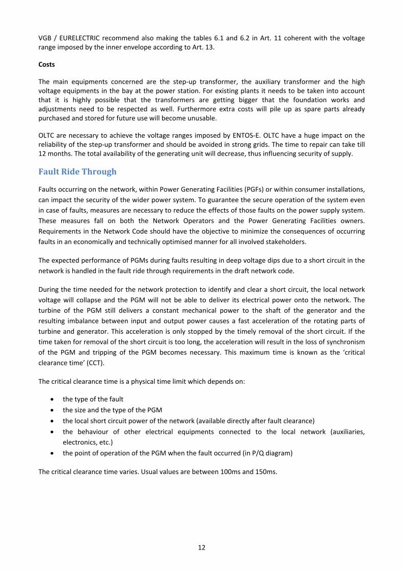
The critical clearance time is a physical time limit which depends on:
the type of the fault
the size and the type of the PGM
the local short circuit power of the network (available directly after fault clearance)
the behaviour of other electrical equipments connected to the local network (auxiliaries,
electronics, etc.)
the point of operation of the PGM when the fault occurred (in P/Q diagram)
The critical clearance time varies. Usual values are between 100ms and 150ms.

13
When the critical clearance time is exceeded before the fault is cleared and the voltage restored, the PGM
must disconnect from the network to avoid serious damage to its equipment.
Network Operator measures: To minimise the effects of short circuit faults, the Relevant Network
Operator must have installed a proper state of the art network protection system which will ensure that
short circuit faults are cleared in the fastest time possible and in particular faster than 90% of the critical
clearance time.
Power Generating Facility Owner measures: Due to the time needed for a circuit breaker to operate, the
PGF’s protection equipment must ensure that the command signal to disconnect is issued before the full
critical clearance time is past. Otherwise, the unit will have lost synchronism before disconnection is
achieved. The PGF owner shall implement a trip time for such protection equal to 90% of the critical
clearance time. This is an essential measure to prevent severe damage and long outages.
If the fault occurs in a grid area with many significant generators and the critical clearance time is not
respected, then there is a serious security of supply risk.
VGB / EURELECTRIC have got negative feedback from vendors and manufacturers to design large
generators FRT capable with a 250ms critical clearance time. For smaller generators, this entails significant
extra costs for generators, turbine governors, energizing systems and control systems. A Cost Benefit
Analysis should be performed to compare these costs with the eventual costs of upgrading the Network
Operators protection systems to achieve a faster fault clearance time. As part of this CBA, the benefits of
harmonising the Fault Ride Through profile across all control areas has to be demonstrated, due to the
substantial diversity of the grid protection system design at EU level.
Needed justification:
i. The requirement of critical clearance time of more than 150 ms for power plants makes only sense
for substations where a “circuit‐breaker‐failure backup” system is installed. As far as we know, such
backup systems are mainly installed in 400 kV substations.
In substations without a “circuit‐breaker‐failure backup” system, the fault clearance time is 130 ms
with a modern redundant protection system and a modern circuit‐breaker. The clearance time is
determined by:
‐ 45 ms for the protection device
‐ 45 ms for the mechanical activation of the circuit‐breaker
‐ 40 ms for the arc extinction in the circuit‐breaker.
Even older circuit‐breakers can achieve fault clearing within 150 ms. If the circuit‐breaker does not
clear the fault, a back‐up in the neighbouring substations will clear the fault after 500 ms or more.
In substations with a “circuit‐breaker‐failure backup” system, a state of the art protection system
and modern circuit‐breaker can eliminate every fault in backup in 200 ms. The clearance time is 130
ms as mentioned above. When operating in backup, the additional time is:
‐ 20 ms for a waiting time period after the refusal to trip of the first circuit‐breaker

14
‐ 85 ms for the opening of the backup circuit‐breaker.
The total clearance time is 200 ms. Imposing more than 200 ms effectively means that the TSO has
not installed state of the art apparatus in the substation.
A large majority of power plants is connected to substations without a “circuit‐breaker‐failure
backup” system where the fault clearance time is always lower than 150 ms or higher than 500 ms.
Only power plants connected to substations with a “circuit‐breaker‐failure backup” system need a
critical clearance time of 200 ms and nothing more.
ii. Review of the existing national network codes shows that nearly all TSOs expect to clear short
circuits resulting in severe voltage dips in 150ms or less. This value comes from a global
optimisation performed in the past time where electrical systems were integrated, balancing
performances and costs between generation and transmission.
However, ENTSO‐E has proposed in the draft code that PGFs should expect severe short circuits not
be cleared until 250ms in the future. This dramatic reduction in performance expected from the
Network Operator’s protection systems is a significant degradation from existing practise and has
severe implications for existing PGFs. Despite the common statement of all stakeholders for a
150ms critical clearance time, ENTSO‐E has refused during the last RfG Users Group to set the
critical clearance time to 150ms in all synchronous area except for Nordic, arguing that TSOs may in
the future need a greater critical clearance time once again, without sound justification based on
CBA. TSOs may currently define CCT for their area on a lower level as this is a non‐exhaustive
requirement. However, for PGF owners it is an undue risk that they have to expect larger CCT in the
future whereby TSO shift costs to PGFs without justification.
The costs for loss of Equivalent Operating Hour (EOH) are also not considered by the code and
would mean an additional shifting of these costs to the PGM owner.
Alternative Solutions
VGB / EURELECTRIC propose the code to consider the following values for the Maximum Clearance Time
Synchronous area Maximum Clearance Time Without Circuit Breaker Failure Backup Systems
Maximum Clearance Time With Circuit Breaker Failure
Backup Systems
Continental Europe 150ms 200ms
Nordic 250ms 250ms
Great Britain 150ms 200ms
Ireland 150ms 200ms
Baltic 150ms 200ms

15
Power by falling frequency
Needs and feasibility
Controlling power with falling frequency cannot ignore physics applicable for each type of PGM (gas turbines, hydro, boiler, etc.). This requirement is influenced by the size of the headroom.
For example, gas turbines:
‐ maintaining initial power when the frequency falls is not possible between 50Hz and approx. 49 Hz as indicated in the next graph (Source: Siemens)
‐ limitations occur because of "rotating stall": compressor pumping can occur depending on rotor speed and other parameters like ambient temperature and output power. It is well known, that such a rotating stall may lead to the disintegration of a gas turbine.
Commissioning and testing of such systems under real conditions is not possible. The risk exists during
normal operation to trip the plant (meaning a Fast Shut Down). Reliability of continued operation at low
frequencies has to prevail above a higher output with less reliability. Furthermore the behaviour of some
technologies at low frequencies depends strongly on ambient conditions.
This graph from Siemens shows the power output of a gas turbine at falling frequencies for various ambient temperatures. The requirements according to Art.8 (Figure 2) are outlined in this graph. The conclusion is that the capacity decreases also for frequencies outside the area requested by the code.
Alternative Solutions
As it is written in NC RfG, this requirement allows TSOs to adapt or change dramatically the technical conditions (“Applicability of this reduction is limited to a selection of affected generation technologies and may be subject to further conditions defined by the Relevant TSO while respecting the provisions of Article 4(3).”).
Considering the necessity to take into account the physical characteristics of the PGM and the environmental need to maximise its efficiency and its power output, VGB / EURELECTRIC propose two options to define the requirement:

16
i. a general statement without values for parameters granting maximum efficiency and output for each PGM at falling frequency
ii. a detailed statement for each type of PGM requesting active power reduction with falling frequency with values for parameters.
Costs
As currently written, the requirement imposes to operate a gas turbine at about 97% of its nominal capacity instead of 100%, thereby decreasing its efficiency by 1 percentage point and resulting in higher CO2 emission. At an average price of 65 EUR/MWh for a CCGT, this operational constraint will increase the price with 0.65 EUR/MWh. For an open cycle gas turbine, the additional cost will even be higher (about 1 EUR/MWh).
Information exchange
ENTSO‐E’s requirements related to information exchange (in article 9.2.5.d) are too general because of the
binding character of the code. Because of the need to harmonise the system operation codes and the
associated inter TSOs coordination, only a list of minimum mandatory signals should be defined. The usage
of the data provided by the signals shall be clearly stated.
Besides, ENTSO‐E requests in article 10.2.f six specific signals for FSM monitoring, without considering the
feasibility and the security constraints. VGB / EURELECTRIC’s experience shows that cyber protection or
uncertainties of the calculation make usage and reliability of certain data very difficult. PGF owners cannot
accept direct access by TSOs to the digital control systems due to cyber security reasons.
The signals requested by the code should be defined in a functional way including all relevant constraints as
cyber security and TSOs shall be obliged to disclose the usage of the signals.
As already mentioned, this requirement will generate many misinterpretations and disputes.
Alternative Solutions
VGB / EURELECTRIC recommend a deeper coordination with stakeholders to define a minimum list.
Fault Recording Device
There is no doubt about the necessity to record and timestamp the electrical signals at the plant interface
to analyse electrical faults and events.
All the parameters listed in the code are intended to be used by the Relevant Network Operator or
Relevant TSO for the assessment of PGF performance. As all performance criteria in the network Code are
defined at the connection point, i.e. in the HV network, it is obvious that the instrumentation should be
installed at that location.
As far as VGB / EURELECTRIC understand, no code imposes TSO to have their own Fault Recording Device.
It is the responsibility of TSOs to perform the analysis of grid events and they should use their own
recording devices to do so.

17
Even though there is no need to impose PGF owners to have their own Fault Recording Device, VGB /
EURELECTRIC recommend PGG owners to have them.
It should be the sole decision of the PGF Owners to decide to install a Fault Recording Device at its premises
to provide fault recording and dynamic system behaviour monitoring (not only voltage, active oower,
reactive power, and frequency; but also current, breaker positions, etc.)
Since
‐ the use of such instrumentation is for the Relevant Network Operator,
‐ the location of the installation of the instrumentation is under the control of the Relevant Network
Operator,
‐ the PGF Owner has no equipment beyond the HV connections of the generator step‐up
transformer,
The instrumentation required to be installed for monitoring the fault performance, dynamic performance and power quality indices should be installed by the Relevant Network Operator to their own specification. This is currently the case for the Fault Recording Device used by TSOs for their own bays.
VGB / EURELECTRIC see the risk that ENTSO‐E shifts the cost of the Fault Recording Device from TSOs to Generators. This option might even be understood if it was the choice of National Regulators and Authorities. However, there is no technical benefit from installing such equipment within the PGF and the data gained from the PGF would be very difficult to translate to the connection point leading to disputes and confusion.
Alternative Solutions
The Fault Recording Device should be specified and installed by TSOs on their property. Recording devices
are already installed in most substations to record faults on grid elements (lines / cables / transformers).
Recording faults in the connection of a PFM means only an additional rack in the existing cabinet at a very
low cost.
Costs
The ENTSO‐E solution is not cost optimized because it requires a stand‐alone system in each PGM instead
of additional equipment in the fault recording system of the TSO.
Injection of Reactive Current by PPM at Fault
Needs and feasibility
Short‐circuit currents allow to detect and localize faults in a grid. The short‐circuit currents are injected by power plants in the transmission grids and consequently also in distribution grids. In general transmission grids are meshed and sophisticated protection systems are in place; distribution grids are in general radial and equipped with simple over‐current protection systems. The over‐current relays order a trip of the circuit‐breaker at currents far higher than the rated current.
Art. 15 allows the national authorities to impose for Power Park Modules (PPM) above 1 MW to inject a reactive current at fault in the network. This current is limited to the rated current.

18
The major characteristic of a PPM is the intermittent nature of the power injection. This would mean that depending on the status (injecting power or not) of the PPM, a short‐circuit current will or will not be injected by the PPM imposing different protection schemes for the affected grid.
If connected at DSO level, VGB sees a number of problems due to the different flows of the fault current depending on the operational status of the PPM. But it is up to DSOs to formulate their point of view
If connected at TSO level, this feature has sense, but the specifications of 10 ms and 60 ms in Art. 15.2.b.2 are not realistic according to information from VESTAS and GE. It is true that GE made some experiments achieving 10 ms reaction time period, but this was under well‐defined grid conditions without any guarantee that it is also applicable to industrial grid conditions. The comment of a manufacturer was simple: “With a time period of only 10 ms, I fear to inject flicker into the grid”. This provision is not feasible for wind parks connected at TSO level because the specifications are not according to proven technology.
Alternative Solutions
VGB / EURELECTRIC support EWEA proposal for Art. 15.2.b.2:
“The Power Park Module […] shall be capable of providing at least 90% of the additional reactive Current (positive sequence of the fundamental) within a time period specified by the Relevant TSO, which shall not be less than 60 milliseconds The target value of this additional reactive Current […] shall be reached with an accuracy of -10%/+20% (of rated current) within 100 milliseconds from the moment the voltage deviation has occurred as further specified […]. Below 40 % of the retained voltage, reactive current shall be supplied as far as technically feasible.”
Changes to, Modernization of or Replacement of Equipment
ENTSO‐E’s requirements (“changes to, modernisation and replacement” Art. 10.6.g) are not proportionate and are mixed up.
‐ First, it should be the responsibility of the PGF owner to inform the Relevant Network Operator (RNO) on the functional changes/modernisation /replacement of equipments.
‐ Equipments are changed / upgraded either to maintain the plant systems with the same functions and performances (replacement) or to give the plant systems new functions and new performances (modernization). Therefore replacement and modernisation cannot be considered at the same level in the code when considering compliance to the requirements.
NEED FOR MODERNISATION
It is unlikely that the RNO has the expertise to assess the impacts of a retrofit on the performances related to the NC RfG. Modernisation is needed for functional reasons or for solving technology/industrial obsolescence.
This impact assessment of the modernisation should be a PGF owner responsibility. If the modernisation is caused by obsolescence and keeps the performance unchanged, there is no reason to request the compliance with the NC. Modernisation does not change the design bases of a PGF and therefore the technical basis remains the same, when for example the voltage regulator or the block protection needs to be replaced. The technical capability is unchanged in that case, thermodynamics, turbine, generator and main transformer remaining with the same behaviour.
REPLACEMENT OF EXISTING EQUIPMENT WITH SPARE PARTS

19
Most of the existing generating units have standardized components built with standardized parts. PGO have bought spare components to reduce the outage durations and often pools of spare parts from manufacturers of identical design have been ordered to cover the PGM fleets. Designing changed replacement parts, if possible at all, is expensive and will take long delivery times!
Mainly, these components have been bought at the commissioning date of the power plant and were compatible with then standards used by grid components.
There is no need to request “the use of existing spare components that do not comply with the requirements has to be agreed” unless it has been evidenced by the RNO that the absence of retrofit will lead to cross border issue or to system security threats. However, in such a case the relevant requirement of the NC for RfG would have to be adapted to existing plants according to the provisions in Art. 3(2).
Considering the “cost balanced” concept brought up in article 4.2, it is interesting to notice that no stakeholder has requested during the consultation “the use of existing spare components by TSOs on grid equipments that are not compatible with the requirements applicable for generators has to be agreed by the Stakeholders”.
Alternative Solutions
To propose a new writing for Art. 10.6.g:
“With regard to modernization of equipment of Power Generating Modules, any Power Generating Facility Owner intending to change plant and equipment of the Power Generating Module that may have an impact on the grid connection and on the interaction, such as turbines, alternators, converters, high‐voltage equipment, protection and control systems (hardware and software), shall notify in advance (in accordance with agreed or decided national timescales) the Relevant Network Operator in case it is reasonable to foresee that these intended changes may affect the fullfillment of requirements of this Network Code and shall, while respecting the provisions of Article 4(3), agree on these requirements before the proposals are implemented with the Relevant Network Operator in coordination with the Relevant TSO.
With regard to replacement of equipment or to use of spare parts in Power Generating Modules the compliance with the requirements will not be requested if the new equipment has the same functions and performances.”
Categorisation
Except a few paragraphs in Art. 3.6, there is no document discussing the allocation of requirements to categories, no clear explanation of the usage of categories in system planning and operation, and no sound definition of category choices and thresholds.
How “Power Generating Facility Owners shall assist and contribute to this determination of the threshold and provide the relevant data as requested by the Relevant TSO” if they do not have any view on the choices at the origin of the thresholds in Table 1 and on associated reasons?
The Framework Guidelines clearly state (in 2.1) that: “The network code(s) shall specify the criteria and methodology for the definition of significant grid users.” The definition of “significant” is exaggerated for Type A generators (“Power Generating Module which is deemed significant on the basis of its impact on the cross‐border system performance via influence” ) unless it is proven that a group of identical generators having the same frequency behaviour can represent a clear threat for system stability.

20
The methodology as described in the code to identify significant generators is too vague, ignores the voltage level at the connection point below 110kV for the categorisation and assumes that any kind of generator (>800 W) is supposed to become a threat for the system security, which is obviously excessive.
Two mains issues arise on the classification of PGM:
i. Contrary to the ACER’s Framework Guidelines the classification of generators does not consider voltage as a criterion for the classification of PGM. A small class B generator (2 MW) will be connected at medium voltage grids and a medium class B (40 MW) generator will connected at high voltage grids. Therefore unique requirements such as FRT for type B small and for type B medium generation are not possible. According to current practice, voltage variations in medium voltage grids are limited to ‐4% to +4% because the European standard EN50160 has to be respected also for low voltage consumers (also additional voltage variations in the low voltage grids apply for those consumers). Consequently imposing identical voltage ranges for generators connected at medium voltage and a high voltage will impose exaggerated requirements for medium voltage connected generators. The justification of the need to impose FRT to all Type B generators is weak. During the stakeholder group at ENTSOE on 22/11/2012, maps of Germany, France and the UK were shown with simulations of voltage during a fault in the 400 kV grid. ENTSO‐E has used these maps to justify the necessity to request FTR for Type B generators. This methodology is not relevant to impose the FRT behaviour of Type B PGM. Most of these PGM are connected to lower voltage levels separated by one or several transformers from the 400kV grid and the voltage of those grids remains higher during a fault in the 400 kV grid. Higher voltages in lower grids were also mentioned during this presentation by ENTSOE on following slides but were not retained in the final conclusion.
ii. The thresholds proposed in Table 1 appear too low when considering cross border issues. Is it absolutely necessary that all PGM in continental Europe greater than 1 MW shall be FRT‐capable? Is it absolutely necessary that all PGM in continental Europe greater than 75 MW have the full features, even if they are not connected to interconnectors or to HV backbones? Thresholds have not been justified and “no significant test” has been applied for their selection.
The process to define generators’ categories seems an open attempt from ENTSO‐E to take control of all new EU generators from 800W to 1700 MW, without justifying the basic needs and benefits. All generators are required to improve their performances. Does this fit with the proportionality requirements?
Retroactivity
Because of the uncertain methodology of CBA, the retroactivity process as described in Article 3.2 should be restricted only to cases preventing severe system security threats. Stakeholders do not have any idea if there will be needs, now or later, to upgrade existing generation. It is unclear why, on a specific requirement, retroactivity would be requested in one country and not in the neighbouring states.
ENTSO‐E has often mentioned the risk of system blackout to justify the requirements and the need for compliance. VGB / EURELECTRIC would like to underline there is no obvious and no immediate direct link between the non‐compliance of one or a few PGFs with particular requirements and a severe electrical

21
system event. TSOs have to plan and operate the system with contingencies (N‐1, etc) according to their knowledge and their confidence in PGM performances. The contingencies are used to cover uncertainties and local temporary non‐compliance. When considering the first phase of CBA process, TSOs should be obliged to assess cliff effects (or scale effects) when thinking about retrofitting existing PGMs. Such lack would be similar to the lack of significance tests in the RfG NC development process.
Alternative Solutions
VGB / EURELECTRIC propose the code to integrate:
‐ A restriction of retroactive application to system security threats ‐ A more detailed CBA methodology including involvement of stakeholders in first phase, significance
tests and cliff effects.
Legal issues
i. The implementation of the provisions will be difficult and will generate a severe administrative
burden due to the poor quality of the consultation:
1. As all provisions can be modified every three years, no guarantees exist for a business
plan covering the total lifetime of a PGF.
2. A request for derogation can only be submitted by the PGF operator, not by
manufacturers. Also a class‐derogation is not allowed even where external regulations
impose more stringent requirements (e.g. nuclear, hydro). Because many requirements
are not applicable to nuclear technology, going through local derogations for
standardised plant will create a lot of additional, avoidable red‐tape. Class‐derogations
should therefore be possible.
3. In order to be proportionate regarding the system needs and to avoid discrimination, the
repeated compliance procedure throughout the lifetime of a PGF (Art. 35.2) should take
place at the same rhythm and not more frequently than every 10 years for all PGF
owners.
ii. The NC RfG and the Frequently Asked Questions, 19 June 2012 page 18 stipulate that the public
consultation will be carried out by the TSO instead of the NRA. As an interested party, the TSO
cannot be the correct party for the consultation or indeed for the CBA which ought to be
undertaken by an independent body appointed by the National Regulatory Authority.
Missing requirements
i. The FG 2.1 stipulates harmonisation as far as technically possible and economically beneficial
throughout the EU. At least the values of parameters decided by the national TSO/NRA should
require coordination at synchronous level.
Alternative Solution: ART 4(3) 3. Where in this code, the determination of the terms and conditions for connection and access to networks or the methodologies to establish them shall be set by the National Regulatory Authorities, or any other entity designated by a Member State in compliance with Directive 2009/72/EC, it shall be made in close cooperation with the neighbouring National Regulatory Authorities, or any other entity designated by a Member State in compliance with Directive 2009/72/EC, of the synchronous area and it shall be subject to prior public consultation of the

22
involved stakeholders and to prior recommendation of the Agency, in accordance with the rules of national law implementing Directive 2009/72/EC, and with the principles of transparency, proportionality and non‐discrimination. 4. Any decision by a Network Operator other than the Relevant TSO and any agreement between a Network Operator other than the Relevant TSO and a Power Generating Facility Owner shall be approved by the Relevant National Regulatory Authority pursuant to the principles of the previous paragraph of the present Article and shall be exercised in compliance with and respecting the Relevant TSO’s responsibility to ensure system security according to national legislation. Further details to ensure this principle may be specified either by national legislation or by agreements between the Relevant TSO and the Network Operators in its Control Area, as the case may be. 5. When this Network Code establishes that a requirement can or shall be agreed, the TSO can determine this requirement if national law assigns it to the TSO and such an assignment was in place at the date of the entry into force of this Network Code.”
ii. A description of all derogations is not publicly available. This is a violation of the principle of
“openness of government”.
iii. More generally, when considering system evolution, there is a big risk of lots of derogation
during the implementation phase10. To make matters worse, no change process has been
identified that could open up the code for future adaptation or evolution.
iv. We are missing a requirement for TSOs to coordinate transparently when implementing the
code (principle of openness of government).
v. The network code must aim at striking a balance between achieving high overall efficiency and
lowering the total cost for all involved stakeholders. No impositions for TSO are described in
the network code related to voltage regulation capacity (the voltage can be regulated by the
PGF and by the TSO/DSO).
vi. Article 10.2.c.4 is an excellent example of unclear provision: “The Frequency Response
Deadband of Frequency deviation and Droop are selected by the TSO and must be able to be
reselected subsequently (without requiring to be online or remote) within the given frames in
the table 4.”
In a general way, the process allowing TSOs to reselect parameters should garantee the
technical11 and the industrial feasibility.
Conclusions
This paper has highlighted some crucial requirements stemming from ENTSO‐E draft NC RfG that generators feel particularly strong about. Taking a pro‐active stance and using concrete evidence from the RfG code and available information as much as possible, the paper shed lights on those requirements which are:
10 Some existing provisions are out of the ranges proposed by ENTSO‐E, for example the fault ride through Tclear parameter in Poland which is 120ms, below the proposed range of 140‐250ms. The second sentence of the grey bullet on page 34 of the document “Requirement In The Context Of Present Practices” appears to be incorrect. 11 For instance, depending on the technology, a droop value may be applicable to switch from normal operation to islanding operation.

23
Not technically feasible (e.g. reactive power ranges) Contradicting requirements contained in other network codes being developed by ENTSO‐E (e.g.
frequency ranges for limited time period of operation) Put disproportionate burdens onto power generators ‐ without achieving societal benefits such as
increased reliability of the grid, hence reduced risk of blackouts (e.g. voltage ranges) Can be re‐drafted taking into account a fairer burden‐sharing between PGF owners and TSOs (e.g.
fault recording devices)
**************************************

24
GLOSSARY
CBA Cost Benefit Analysis
CCGT Combined Cycle Gas Turbine
CIGRÉ Conseil International des Grands Réseaux Électriques
DIN Deutsche Institute für Normung
EOH Equivalent Operating Hour
FRT Fault Ride Through
FSM Frequency Sensitivity Mode
IEC International Electrical Commission
MVA Mega Volt Amps
NRA National Regulatory Authority
OLTC On Load Tap Changer
PGF Power Generating Facility
PGM Power Generating Modules
PPM Power Park Module
RNO Relevant Network Operator