Embed Size (px)
DESCRIPTION
Parameter Mapping NokiaSiemensEricsson
Citation preview
No
kia
Ob
jec
t
No
kia
Lo
ng
Na
me
No
kia
na
me
Sie
me
ns
Ob
jec
t
WCEL Cell Barred CellBarred cell rslc
WCEL Cell Reserved for operator use Cell_Reserved cell rslc
NA NA NA cell rslc
WCEL Cell reselection triggering time Treselection cell rslc
WCEL Minimum required quality level in the cell QqualMin cell rslc
WCEL Minimum required RX level in the cell QrxlevMin cell rslc
HOPI Cell Re-selection Minimum Quality AdjiQqualMin euc
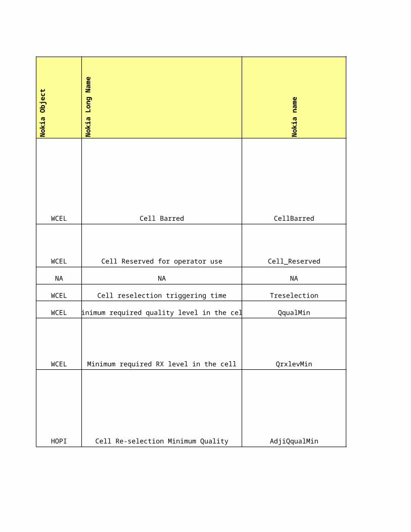
HOPS Cell Re-selection Minimum Quality AdjsQqualMin euc
WCEL Intra-frequency cell re-selection indicator IntraFreq_Cell_Reselect_Ind cell rslc
WCEL Cell barred period Tbarred cell rslc
WCEL Cell reselection hysteresis 1 Qhyst1 cell rslc
WCEL Cell reselection hysteresis 2 Qhyst2 cell rslc
WCEL Maximum UE transmission power on DPCH UEtxPowerMaxDPCH cell rslc
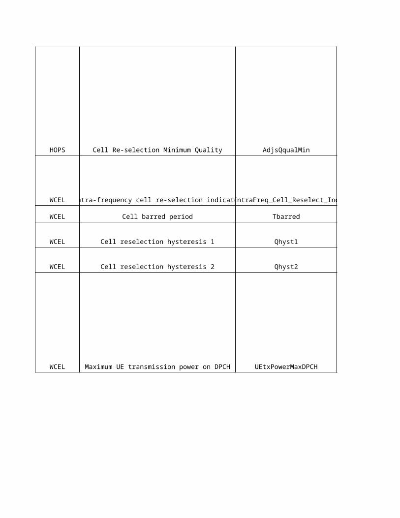
ADJI Maximum UE TX Power on RACH AdjiTxPwrRACH euc
ADJS Maximum UE TX Power on RACH AdjsTxPwrRACH euc
ADJG Maximum UE TX Power on RACH AdjgTxPwrMaxRACH egcNA NA NA cell rslcNA NA NA cell rslcNA NA NA cell rslcNA NA NA cell rslc
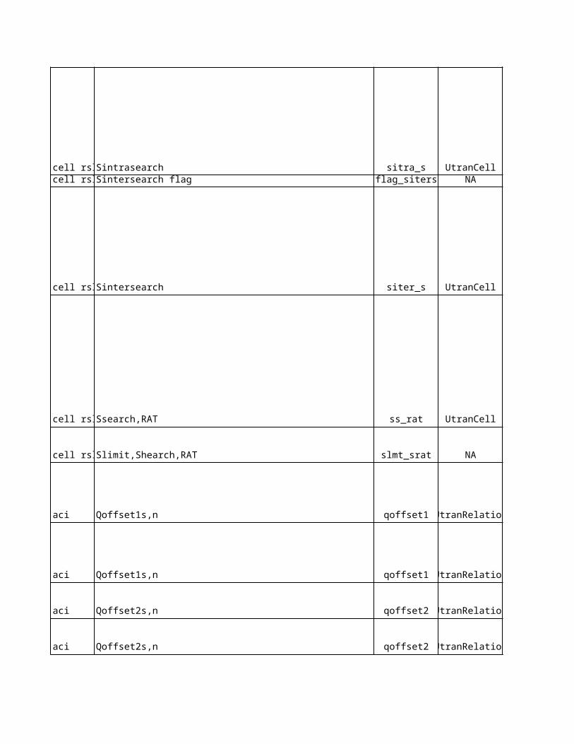
WCEL S intrasearch Sintrasearch cell rslcNA NA NA cell rslc
WCEL S intersearch Sintersearch cell rslc
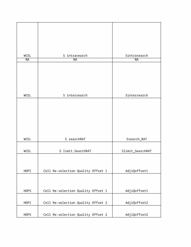
WCEL S searchRAT Ssearch_RAT cell rslc
WCEL S limit,SearchRAT Slimit_SearchRAT cell rslc
HOPI Cell Re-selection Quality Offset 1 AdjiQoffset1 aci
HOPS Cell Re-selection Quality Offset 1 AdjiQoffset1 aci
HOPI Cell Re-selection Quality Offset 2 AdjiQoffset2 aci
HOPS Cell Re-selection Quality Offset 2 AdjiQoffset2 aci
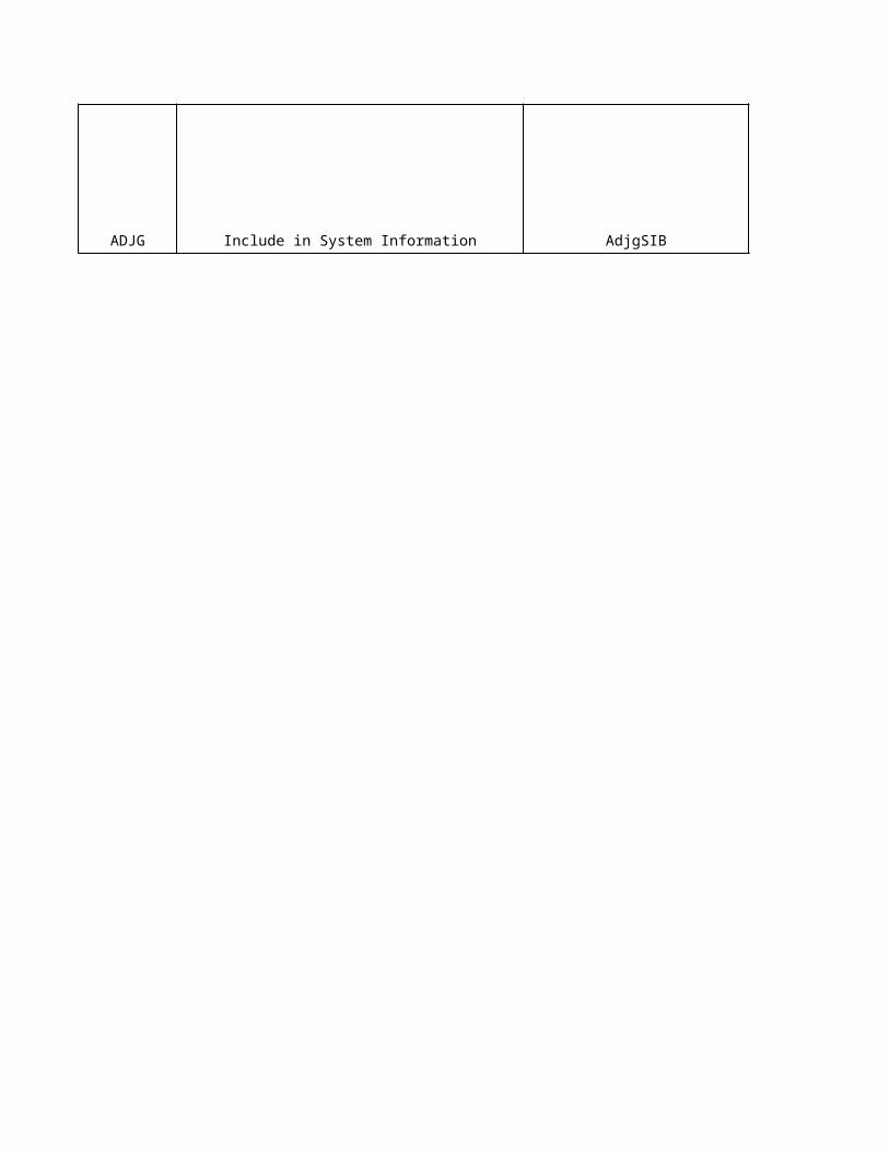
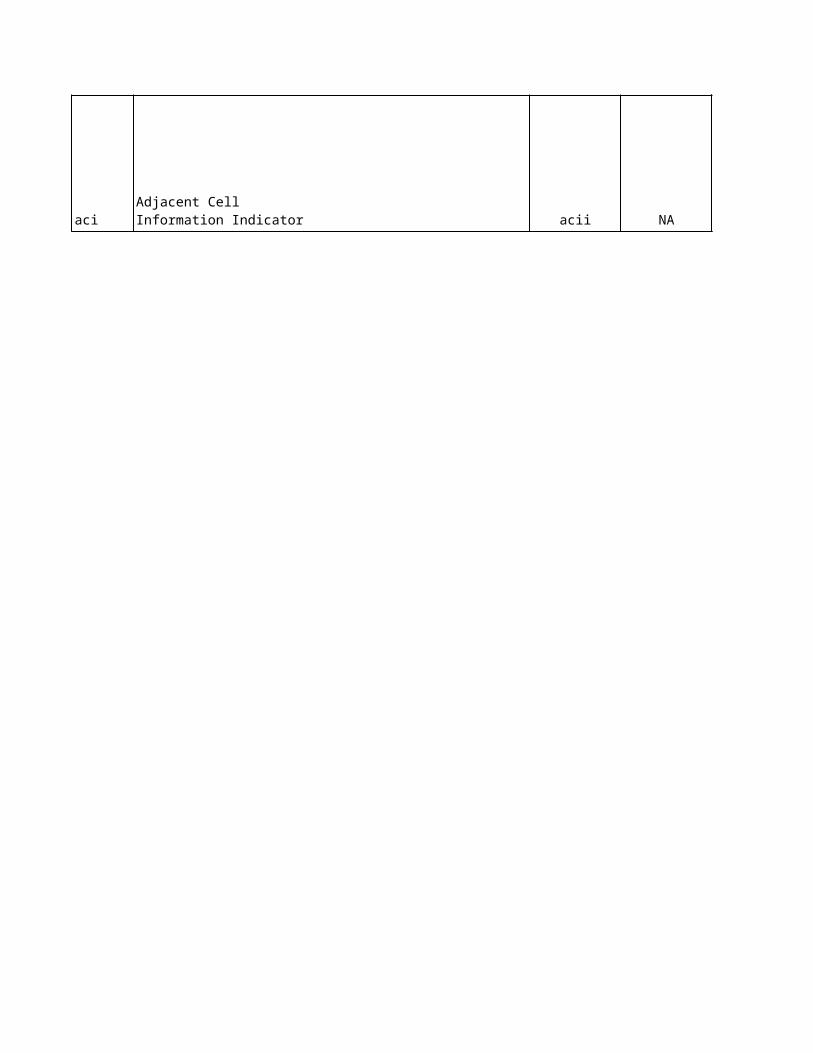
ADJG Include in System Information AdjgSIB aci
Sie
me
ns
Lo
ng
Na
me
Sie
me
ns
na
me
Eri
cs
so
n O
bje
ct
Cell Barred cellbr UtranCell
cellrop UtranCell
csrqm UtranCell
Treselections trslct UtranCell
Qqualmin qqualm UtranCell
Qrxlevmin qrxlevmin UtranCell
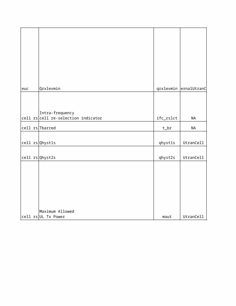
Qqualmin qqualm ExternalUtranCell
Cell Reserved for operator useCell_ selection_ and_reselection_quality_ measure
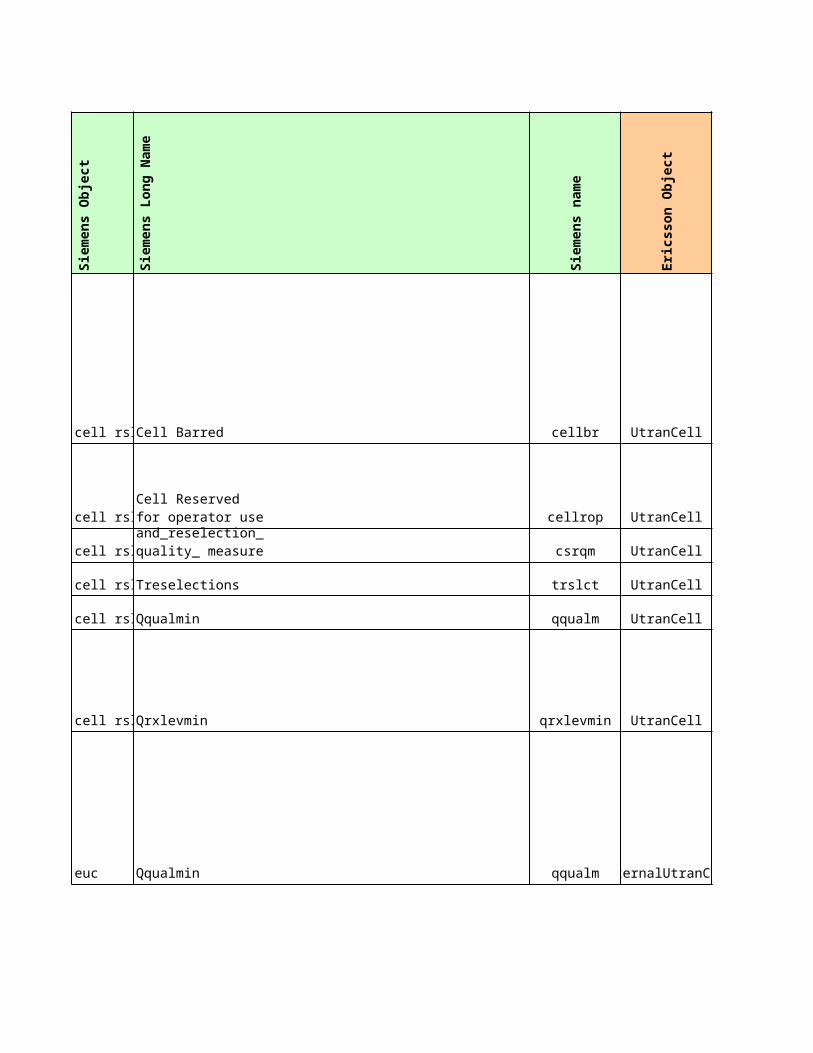
Qrxlevmin qrxlevmin ExternalUtranCell
ifc_rslct NA
Tbarred t_br NA
Qhyst1s qhyst1s UtranCell
Qhyst2s qhyst2s UtranCell
maut UtranCell
maut ExternalUtranCell
Intra-frequency cell re-selection indicator
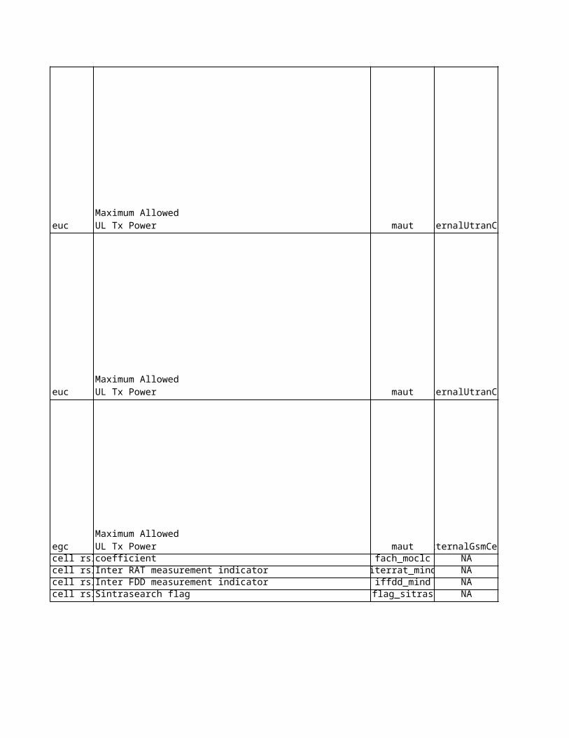
Maximum Allowed UL Tx Power
Maximum Allowed UL Tx Power
maut ExternalUtranCell
maut ExternalGsmCellfach_moclc NA
Inter RAT measurement indicator iterrat_mind NAInter FDD measurement indicator iffdd_mind NASintrasearch flag flag_sitras NA
Sintrasearch sitra_s UtranCellSintersearch flag flag_siters NA
Sintersearch siter_s UtranCell
Maximum Allowed UL Tx Power
Maximum Allowed UL Tx Powercoefficient
Ssearch,RAT ss_rat UtranCell
Slimit,Shearch,RAT slmt_srat NA
Qoffset1s,n qoffset1 UtranRelation
Qoffset1s,n qoffset1 UtranRelation
Qoffset2s,n qoffset2 UtranRelation
Qoffset2s,n qoffset2 UtranRelation
acii NAAdjacent Cell Information Indicator
Eri
cs
so
n L
on
g N
am
e
Eri
cs
so
n n
am
e
No
kia
pro
po
se
d
Sie
me
ns
cu
rre
nt
Eri
cs
so
n c
urr
en
t
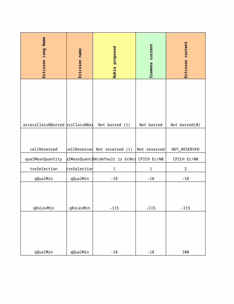
accessClassNBarredaccessClassNBarred Not barred (1) Not barred Not barred(0)
cellReserved cellReserved Not reserved (1) Not reserved NOT_RESERVED
qualMeasQuantity qualMeasQuantityNA(default is EcNo) CPICH Ec/N0 CPICH Ec/N0
treSelection treSelection 1 1 2
qQualMin qQualMin -18 -18 -18
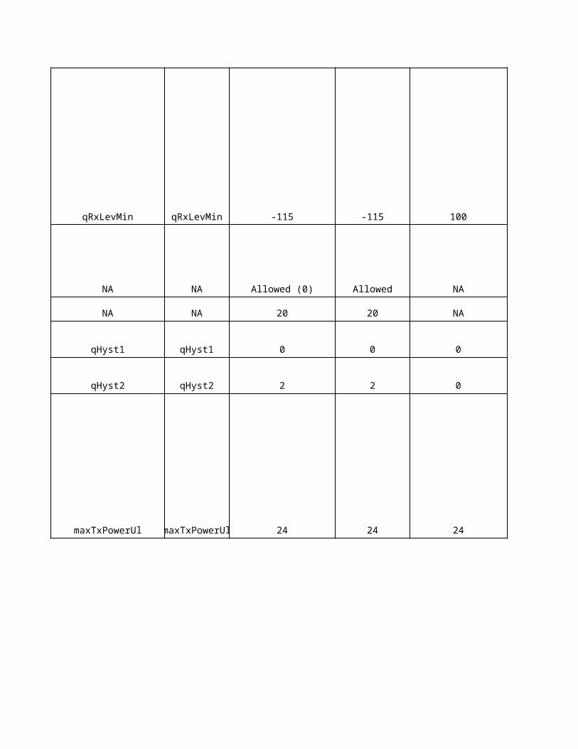
qRxLevMin qRxLevMin -115 -115 -115
qQualMin qQualMin -18 -18 100
qRxLevMin qRxLevMin -115 -115 100
NA NA Allowed (0) Allowed NA
NA NA 20 20 NA
qHyst1 qHyst1 0 0 0
qHyst2 qHyst2 2 2 0
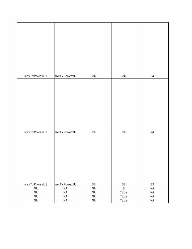
maxTxPowerUl maxTxPowerUl 24 24 24
maxTxPowerUl maxTxPowerUl 24 24 24
maxTxPowerUl maxTxPowerUl 24 24 24
maxTxPowerUl maxTxPowerUl 33 33 33NA NA NA 3 NANA NA NA True NANA NA NA True NANA NA NA True NA
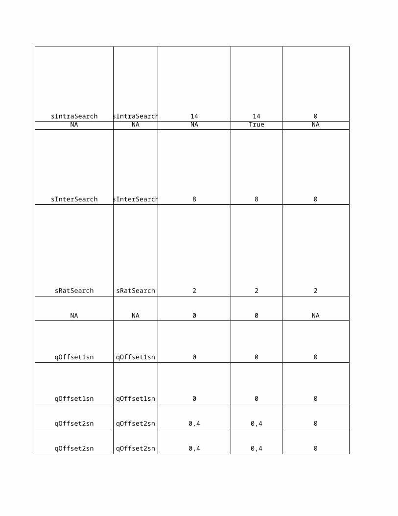
sIntraSearch sIntraSearch 14 14 0NA NA NA True NA
sInterSearch sInterSearch 8 8 0
sRatSearch sRatSearch 2 2 2
NA NA 0 0 NA
qOffset1sn qOffset1sn 0 0 0
qOffset1sn qOffset1sn 0 0 0
qOffset2sn qOffset2sn 0,4 0,4 0
qOffset2sn qOffset2sn 0,4 0,4 0
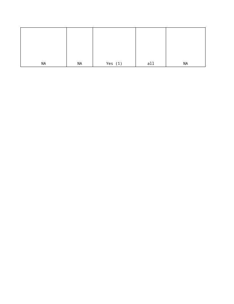
NA NA Yes (1) all NA
Ag
ree
d
No
kia
Un
it
Sie
me
ns
Un
it
Eri
cs
so
n U
nit
- - -
- - -
- - -
s s s
dB dB dB
dBm dBm dBm
dB dB dB
dBm dBm dBm
- - -
s s s
dB dB dB
dB dB dB
dBm dBm dBm
dBm dBm dBm
dBm dBm
dBm dBm dBm- - -- - -- - -- - -
dB dB dB- -
dB dB dB
dB dB dB
dB dB dB
dB dB dB
dB dB dB
dB dB dB
dB dB dB
- - -
No
kia
De
sc
rip
tio
n
NA
The UE triggers the reselection of a new cell if the cell reselection criteria are fulfilled during the time interval Treselection.
The minimum required quality level in the cell (Ec/No).
Defines whether the cell is barred or not. A barred cell is a cell where a UE is not allowed to camp on. Emergency calls shall be allowed in all cells whose barred status is "not barred". When cell status is "barred", the UE is not permitted to select/re-select the cell, not even for emergency calls.
Defines whether the cell is reserved for operator use or not. A reserved cell is a cell on which camping is not allowed, except for particular UEs, if so indicated. When cell status is "not barred" and "not reserved" for operator use the UE may select/re-select this cell during the cell selection and cell re-selection procedures in Idle mode and in Connected mode. When cell status is "not barred" and "reserved" for operator use, the UEs assigned to Access Class 11 or 15 may select/re-select this cell if in the home PLMN. UEs assigned to Access Class in the range 0 to 9 and 12 to 14 shall behave as if cell status "barred" is indicated.
The minimum required RX level in the cell. Note: This parameter is also used to create value for the parameter DeltaQrxlevmin to be sent in SIB3/4 when the used value is < -115.
Determines the minimum required CPICH Ec/No level which must be exceeded by the measurement result of the inter-frequency neighbour cell before the cell re-selection becomes possible.
When the cell is barred, the UE must check between the time interval ‘Cell barred period’, whether the status of the barred cell has changed.
Qhyst1 is used for TDD and GSM cells, and for FDD cells when cell selection and re-selection quality measure is set to CPICH RSCP.
Qhyst2 is used for FDD cells when cell selection and re-selection quality measure is set to CPICH Ec/No.
Determines the minimum required CPICH Ec/No level which must be exceeded by the measurement result of the neighbouring cell before the cell re-selection becomes possible.
Defines whether intra-frequency cell re-selection is allowed or not when the cell is barred. When a cell's status is "barred", the UE is not permitted to select/re-select this cell, except in some cases for an emergency call. If the "Intra-frequency cell re-selection indicator" is set to value "allowed", the UE may select another cell on the same frequency if selection/re-selection criteria are fulfilled. If the "Intra-frequency cell re-selection indicator" is set to "not allowed" the UE shall not re-select even a different cell on the same frequency as the barred cell. For emergency call, the Intra-frequency cell re-selection indicator IE" shall be ignored. "Intra-frequency cell re-selection indicator" is part of SIB3/4 in the case the "cell barred" indicator is true.
This parameter defines the maximum transmission power level a UE can use on DPCH. It is signaled to UE in the Maximum allowed UL TX power IE of a proper RRC message, when a radio link is set up.
This parameter indicates the maximum transmission power level that a UE can use when accessing the neighbouring cell on the RACH. The UE uses the parameter in the cell re-selection procedure. If the maximum output power of the UE is lower than the value of the parameter, the UE adds the power difference (dB value) to the minimum required CPICH Ec/No level, which the measurement result of the neighbouring cell must exceed before the cell re-selection is possible.
NANANANA
The threshold for intra-frequency measurements, and for the HCS measurement rules. Note: If no threshold is given, MS performs measurements.NA
The threshold for inter-frequency measurements, and for the HCS measurement rules. Note: If no threshold is given, MS performs measurements.
This parameter indicates the maximum transmission power level that a UE can use when accessing the neighbouring cell on the RACH. The UE uses the parameter in the cell re-selection procedure. If the maximum output power of the UE is lower than the value of the parameter, the UE adds the power difference (dB value) to the minimum required CPICH Ec/No level, which the measurement result of the neighbouring cell must exceed before the cell re-selection is possible.
This parameter indicates the maximum transmission power level that an UE can use when accessing the GSM neighbour cell on the RACH. The UE uses the parameter in the cell re-selection procedure. If the maximum output power of the UE is lower than the value of the parameter, the UE adds the power difference (dB value) to the minimum required GSM RSSI level, which the measurement result of the GSM neighbour cell must exceed before the cell re-selection is possible.

The RAT-specific threshold for inter-RAT measurement rules. Note: If no threshold is given, MS performs measurements.
Threshold for skipping inter-RAT measurement rules in HCS. Above this RAT specific threshold in the serving UTRA cell, the UE does not need to perform any inter-RATm measurements. Needed only if HCS is used.
This parameter is used in the cell re-selection and ranking between WCDMA cells. The value of this parameter is subtracted from the measured CPICH RSCP of the inter-frequency neighbour cell before the UE compares the quality measure with the cell re-selection/ranking criteria.
This parameter is used in the cell re-selection and ranking between WCDMA cells. The value of this parameter is subtracted from the measured CPICH RSCP of the neighbour cell before the UE compares the quality measure with the cell re-selection/ranking criteria.
This parameter is used in the cell re-selection and ranking between WCDMA cells. The value of this parameter is subtracted from the measured CPICH Ec/No of the inter-frequency neighbour cell before the UE compares the quality measure with the cell re-selection/ranking criteria.
This parameter is used in the cell re-selection and ranking between WCDMA cells. The value of this parameter is subtracted from the measured CPICH Ec/No of the neighbour cell before the UE compares the quality measure with the cell re-selection/ranking criteria.
The parameter indicates whether the GSM neighbour cell is included in the System Information Block 11&12&18 for the cell selection and re-selection procedures. The GSM neighbour cell is included in the system information when the value of the parameter is "yes". If the Wireless Priority Service feature is enabled, then parameter Include in System Information shall be set to have value "yes" for ADJG-0. If the total number of intra-frequency, inter-frequency and GSM neighbour cells, which are included in the System Information, exceeds the physical size of SIB data, the NBAP interface is not able to pack the neighbour cell information into the SIB data and the scheduling of the system information blocks fails. The cell is blocked by the system and an alarm 7771 WCDMA CELL OUT OF USE (BCCH scheduling error) is reported for the cell. Note: The parameter AdjgSIB does not affect GSM measurements in CELL_DCH state of connected mode. That is, all GSM neighbour cells are monitored for the inter-system handover regardless of the value of the parameter AdjgSIB.
Sie
me
ns
De
sc
rip
tio
n
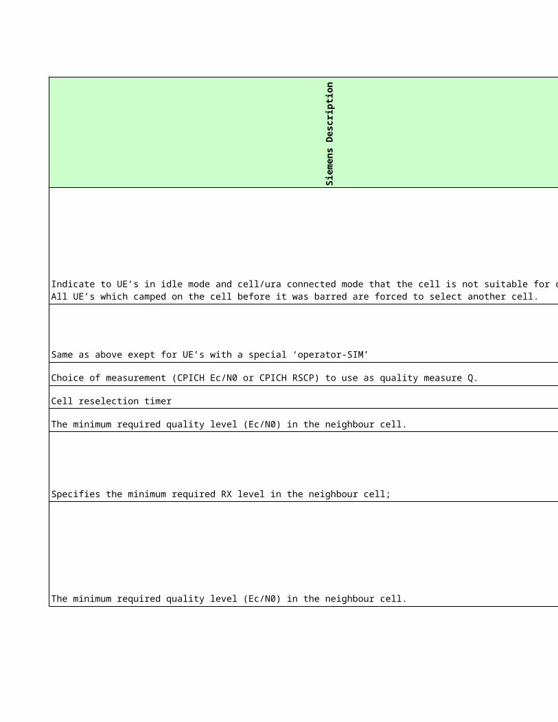
Same as above exept for UE’s with a special ‘operator-SIM’
Choice of measurement (CPICH Ec/N0 or CPICH RSCP) to use as quality measure Q.
Cell reselection timer
The minimum required quality level (Ec/N0) in the neighbour cell.
Specifies the minimum required RX level in the neighbour cell;
The minimum required quality level (Ec/N0) in the neighbour cell.
Indicate to UE’s in idle mode and cell/ura connected mode that the cell is not suitable for camping. All UE’s which camped on the cell before it was barred are forced to select another cell.
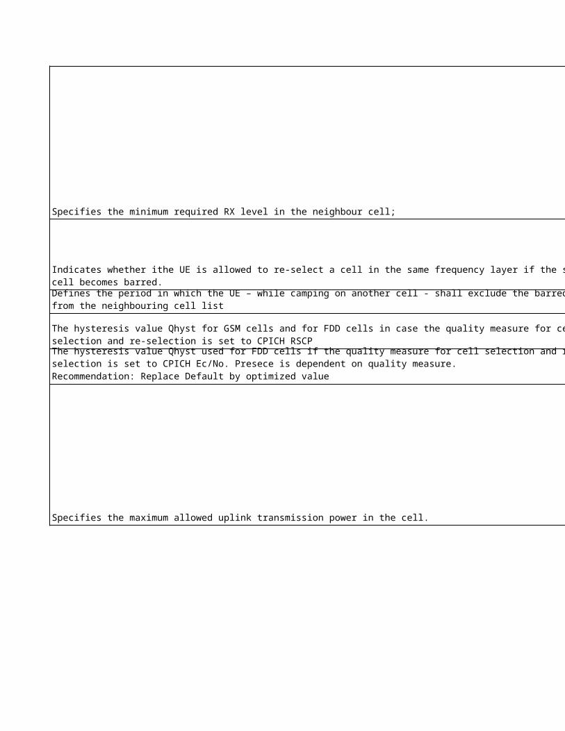
Specifies the minimum required RX level in the neighbour cell;
Indicates whether ithe UE is allowed to re-select a cell in the same frequency layer if the serving cell becomes barred.
Specifies the maximum allowed uplink transmission power in the cell.
Specifies the maximum allowed uplink transmission power in the cell.
Defines the period in which the UE – while camping on another cell - shall exclude the barred cell from the neighbouring cell list
The hysteresis value Qhyst for GSM cells and for FDD cells in case the quality measure for cell selection and re-selection is set to CPICH RSCP
The hysteresis value Qhyst used for FDD cells if the quality measure for cell selection and re-selection is set to CPICH Ec/No. Presece is dependent on quality measure.Recommendation: Replace Default by optimized value
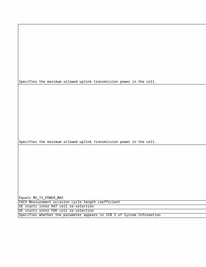
Specifies the maximum allowed uplink transmission power in the cell.
Equals MS_TX_POWER_MAXFACH Measurement occasion cycle length coefficientUE starts inter RAT cell re-selectionUE starts inter FDD cell re-selectionSpecifies whether the parameter appears in SIB 3 of System Information
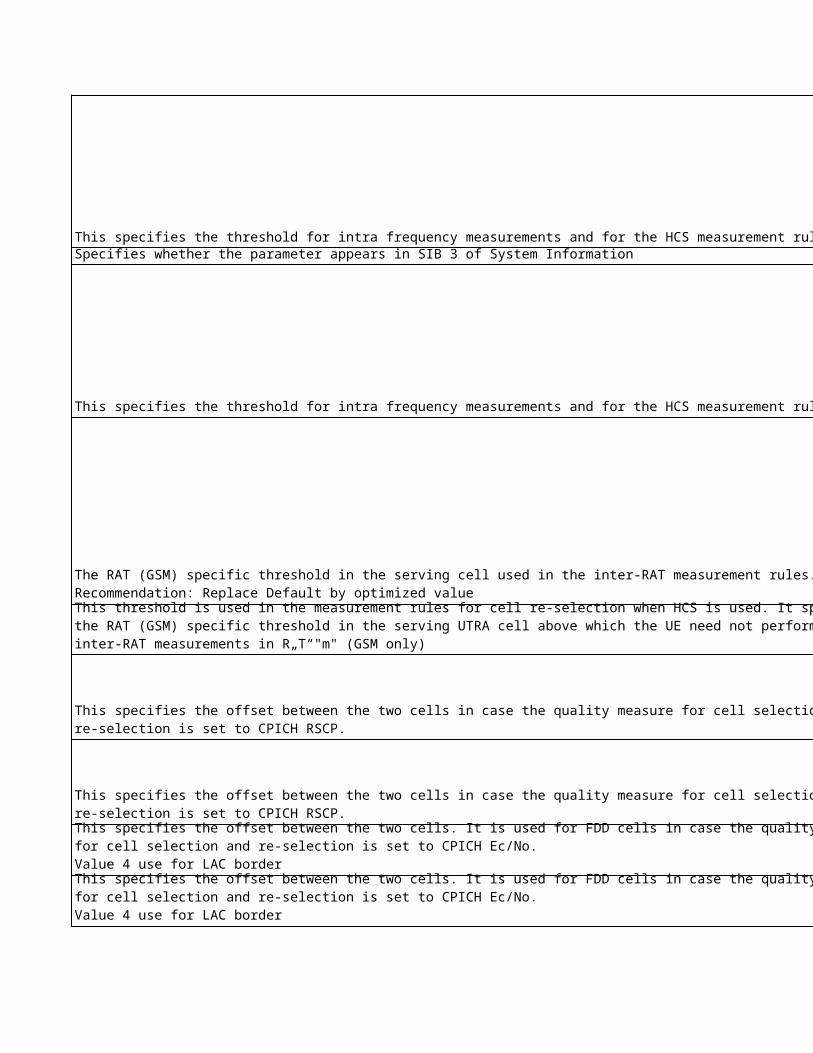
This specifies the threshold for intra frequency measurements and for the HCS measurement rules. Specifies whether the parameter appears in SIB 3 of System Information
This specifies the threshold for intra frequency measurements and for the HCS measurement rules.
The RAT (GSM) specific threshold in the serving cell used in the inter-RAT measurement rules.Recommendation: Replace Default by optimized value
This threshold is used in the measurement rules for cell re-selection when HCS is used. It specifies the RAT (GSM) specific threshold in the serving UTRA cell above which the UE need not perform any inter-RAT measurements in R„T“"m" (GSM only)
This specifies the offset between the two cells in case the quality measure for cell selection and re-selection is set to CPICH RSCP.
This specifies the offset between the two cells in case the quality measure for cell selection and re-selection is set to CPICH RSCP.
This specifies the offset between the two cells. It is used for FDD cells in case the quality measure for cell selection and re-selection is set to CPICH Ec/No.Value 4 use for LAC border
This specifies the offset between the two cells. It is used for FDD cells in case the quality measure for cell selection and re-selection is set to CPICH Ec/No.Value 4 use for LAC border
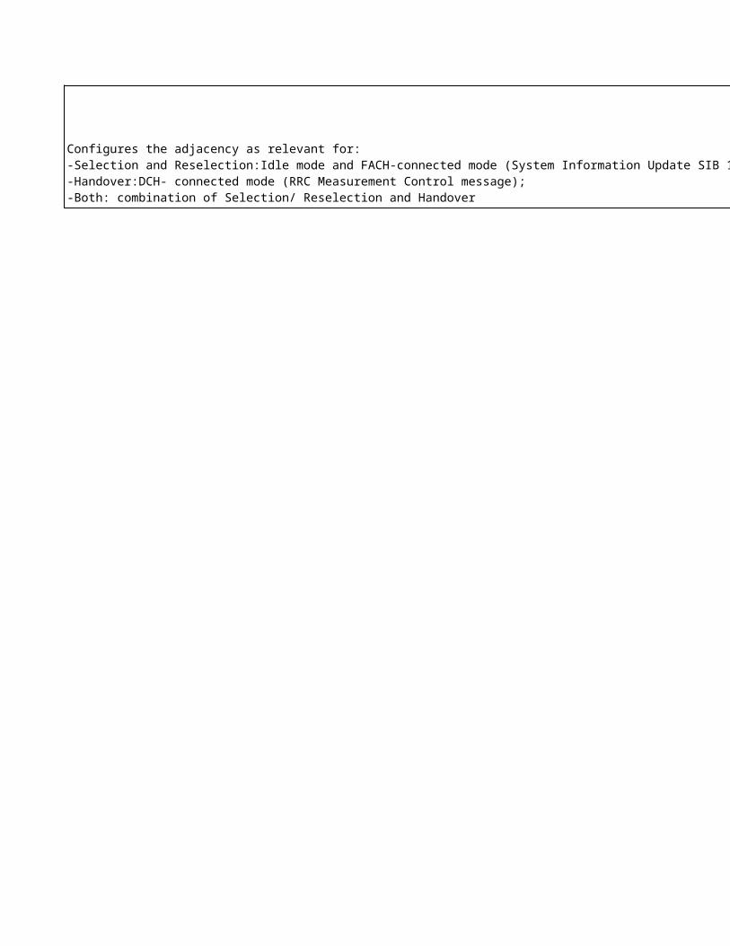
Configures the adjacency as relevant for:-Selection and Reselection:Idle mode and FACH-connected mode (System Information Update SIB 11);-Handover:DCH- connected mode (RRC Measurement Control message);-Both: combination of Selection/ Reselection and Handover
Eri
cs
so
n D
es
cri
pti
on
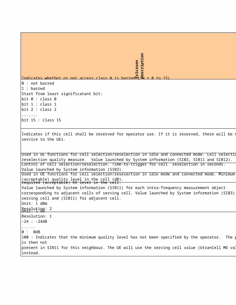
Indicates whether or not access class N is barred ( N = 0 to 15). 0 : not barred1 : barredStart from least significatant bit:bit 0 : class 0 bit 1 : class 1 bit 2 : class 2 .......bit 15 : class 15
Indicates if this cell shall be reserved for operator use. If it is reserved, there will be no service to the UEs.
Used in UE functions for cell selection/reselection in idle and connected mode. Cell selection and reselection quality measure. Value launched by System information (SIB3, SIB11 and SIB12).
Control of cell selection/reselection. Time-to-trigger for cell reselection in seconds. Value launched by System information (SIB3).
Used in UE functions for cell selection/reselection in idle mode and connected mode. Minimum required (acceptable) quality level in the cell (dB).
Used in UE functions for cell selection/reselection in idle mode and connected mode. Minimum required (acceptable) RX level in the cell. Value launched by System information (SIB11) for each intra-frequency measurement object corresponding to adjacent cells of serving cell. Value launched by System information (SIB3) for serving cell and (SIB11) for adjacent cell.Unit: 1 dBmResolution: 2
Used in UE functions for cell selection/reselection in idle mode and connected mode. Minimum required (acceptable) quality level in the cell (dB). Used to set cell border between two cells. Unit: 1 dBResolution: 1-24 : -24dB......0 : 0dB100 : Indicates that the minimum quality level has not been specified by the operator. The parameter is then notpresent in SIB11 for this neighbour. The UE will use the serving cell value (UtranCell MO value) instead.
NA
NA
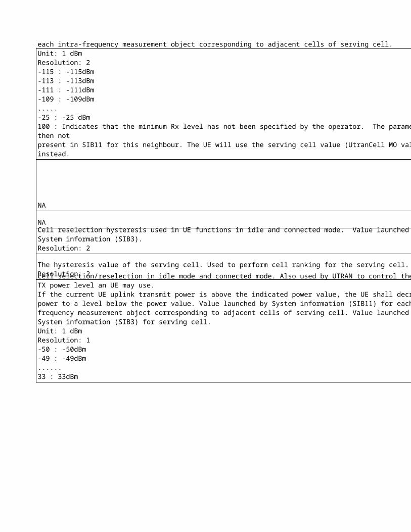
Used in UE functions for cell selection/reselection in idle mode and connected mode. Minimum required (acceptable) RX level in the cell. (dBm). Value launched by System information (SIB11) for each intra-frequency measurement object corresponding to adjacent cells of serving cell.Unit: 1 dBmResolution: 2-115 : -115dBm-113 : -113dBm-111 : -111dBm-109 : -109dBm.....-25 : -25 dBm100 : Indicates that the minimum Rx level has not been specified by the operator. The parameter is then notpresent in SIB11 for this neighbour. The UE will use the serving cell value (UtranCell MO value) instead.
Cell reselection hysteresis used in UE functions in idle and connected mode. Value launched by System information (SIB3).Resolution: 2
The hysteresis value of the serving cell. Used to perform cell ranking for the serving cell. Resolution: 2
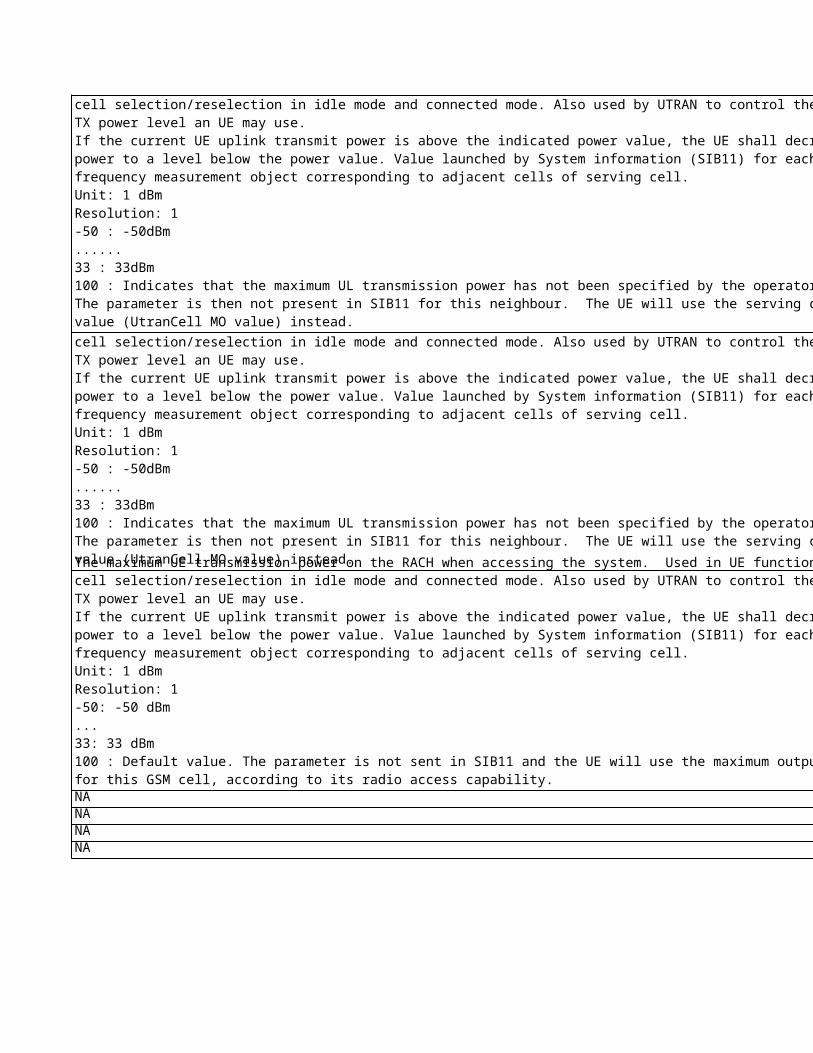
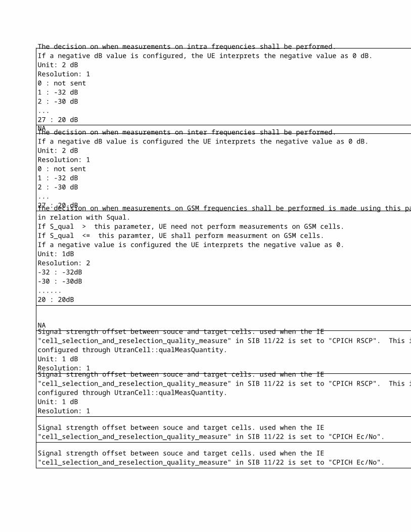
The maximum UE transmission power on the RACH when accessing the system. Used in UE functions for cell selection/reselection in idle mode and connected mode. Also used by UTRAN to control the maximum TX power level an UE may use. If the current UE uplink transmit power is above the indicated power value, the UE shall decrease the power to a level below the power value. Value launched by System information (SIB11) for each intra-frequency measurement object corresponding to adjacent cells of serving cell. Value launched by System information (SIB3) for serving cell. Unit: 1 dBmResolution: 1-50 : -50dBm-49 : -49dBm......33 : 33dBm
The maximum UE transmission power on the RACH when accessing the system. Used in UE functions for cell selection/reselection in idle mode and connected mode. Also used by UTRAN to control the maximum TX power level an UE may use. If the current UE uplink transmit power is above the indicated power value, the UE shall decrease the power to a level below the power value. Value launched by System information (SIB11) for each intra-frequency measurement object corresponding to adjacent cells of serving cell. Unit: 1 dBmResolution: 1-50 : -50dBm......33 : 33dBm100 : Indicates that the maximum UL transmission power has not been specified by the operator.The parameter is then not present in SIB11 for this neighbour. The UE will use the serving cell value (UtranCell MO value) instead.
NANANANA
NA
The maximum UE transmission power on the RACH when accessing the system. Used in UE functions for cell selection/reselection in idle mode and connected mode. Also used by UTRAN to control the maximum TX power level an UE may use. If the current UE uplink transmit power is above the indicated power value, the UE shall decrease the power to a level below the power value. Value launched by System information (SIB11) for each intra-frequency measurement object corresponding to adjacent cells of serving cell. Unit: 1 dBmResolution: 1-50 : -50dBm......33 : 33dBm100 : Indicates that the maximum UL transmission power has not been specified by the operator.The parameter is then not present in SIB11 for this neighbour. The UE will use the serving cell value (UtranCell MO value) instead.
The maximum UE transmission power on the RACH when accessing the system. Used in UE functions for cell selection/reselection in idle mode and connected mode. Also used by UTRAN to control the maximum TX power level an UE may use. If the current UE uplink transmit power is above the indicated power value, the UE shall decrease the power to a level below the power value. Value launched by System information (SIB11) for each intra-frequency measurement object corresponding to adjacent cells of serving cell.Unit: 1 dBmResolution: 1-50: -50 dBm...33: 33 dBm100 : Default value. The parameter is not sent in SIB11 and the UE will use the maximum output power for this GSM cell, according to its radio access capability.
The decision on when measurements on intra frequencies shall be performed. If a negative dB value is configured, the UE interprets the negative value as 0 dB.Unit: 2 dBResolution: 10 : not sent 1 : -32 dB2 : -30 dB...27 : 20 dB
The decision on when measurements on inter frequencies shall be performed. If a negative dB value is configured the UE interprets the negative value as 0 dB.Unit: 2 dBResolution: 10 : not sent1 : -32 dB2 : -30 dB...27 : 20 dB
NA
NA
The decision on when measurements on GSM frequencies shall be performed is made using this parameter in relation with Squal. If S_qual > this parameter, UE need not perform measurements on GSM cells.If S_qual <= this paramter, UE shall perform measurment on GSM cells. If a negative value is configured the UE interprets the negative value as 0.Unit: 1dBResolution: 2-32 : -32dB-30 : -30dB......20 : 20dB
Signal strength offset between souce and target cells. used when the IE "cell_selection_and_reselection_quality_measure" in SIB 11/22 is set to "CPICH RSCP". This is configured through UtranCell::qualMeasQuantity.Unit: 1 dBResolution: 1
Signal strength offset between souce and target cells. used when the IE "cell_selection_and_reselection_quality_measure" in SIB 11/22 is set to "CPICH RSCP". This is configured through UtranCell::qualMeasQuantity.Unit: 1 dBResolution: 1
Signal strength offset between souce and target cells. used when the IE "cell_selection_and_reselection_quality_measure" in SIB 11/22 is set to "CPICH Ec/No".
Signal strength offset between souce and target cells. used when the IE "cell_selection_and_reselection_quality_measure" in SIB 11/22 is set to "CPICH Ec/No".
No
kia
Ob
jec
t
No
kia
Lo
ng
Na
me
No
kia
na
me
Sie
me
ns
Ob
jec
t
NA NA NA rnc
NA NA NA rnc
NA NA NA rncNA NA NA rncNA NA NA rncNA NA NA rncNA NA NA rncNA NA NA rncNA NA NA rnc
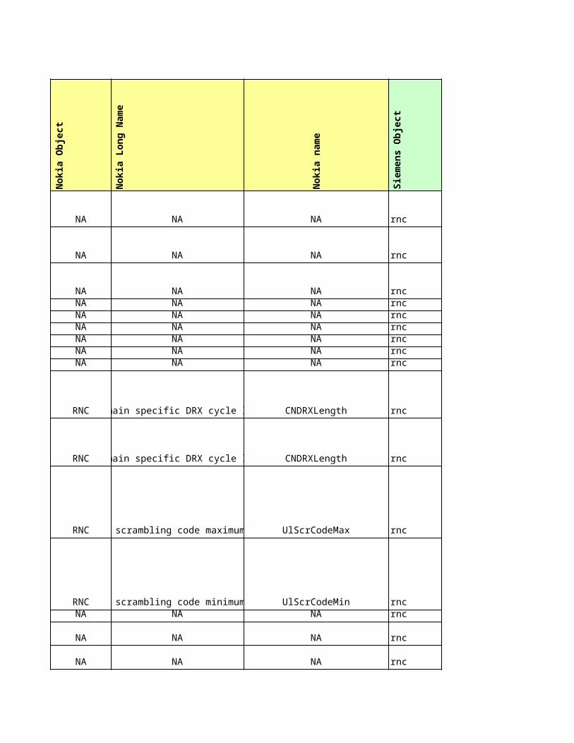
RNCCN domain specific DRX cycle length CNDRXLength rnc
RNCCN domain specific DRX cycle length CNDRXLength rnc
RNCUplink scrambling code maximum value UlScrCodeMax rnc
RNCUplink scrambling code minimum value UlScrCodeMin rncNA NA NA rnc
NA NA NA rnc
NA NA NA rnc
NA NA NA rncNA NA NA rncNA NA NA rnc
NA NA NA rncNA NA NA rncNA NA NA rncNA NA NA rnc
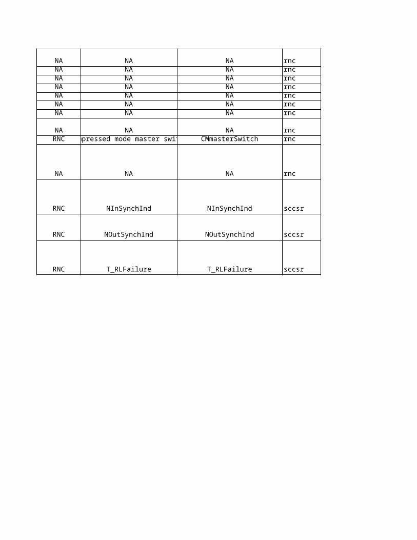
NA NA NA rncRNC Compressed mode master switch CMmasterSwitch rnc
NA NA NA rnc
RNC NInSynchInd NInSynchInd sccsr
RNC NOutSynchInd NOutSynchInd sccsr
RNC T_RLFailure T_RLFailure sccsr
Sie
me
ns
Lo
ng
Na
me
Sie
me
ns
na
me
Eri
cs
so
n O
bje
ct
Eri
cs
so
n L
on
g N
am
e
Eri
cs
so
n n
am
e
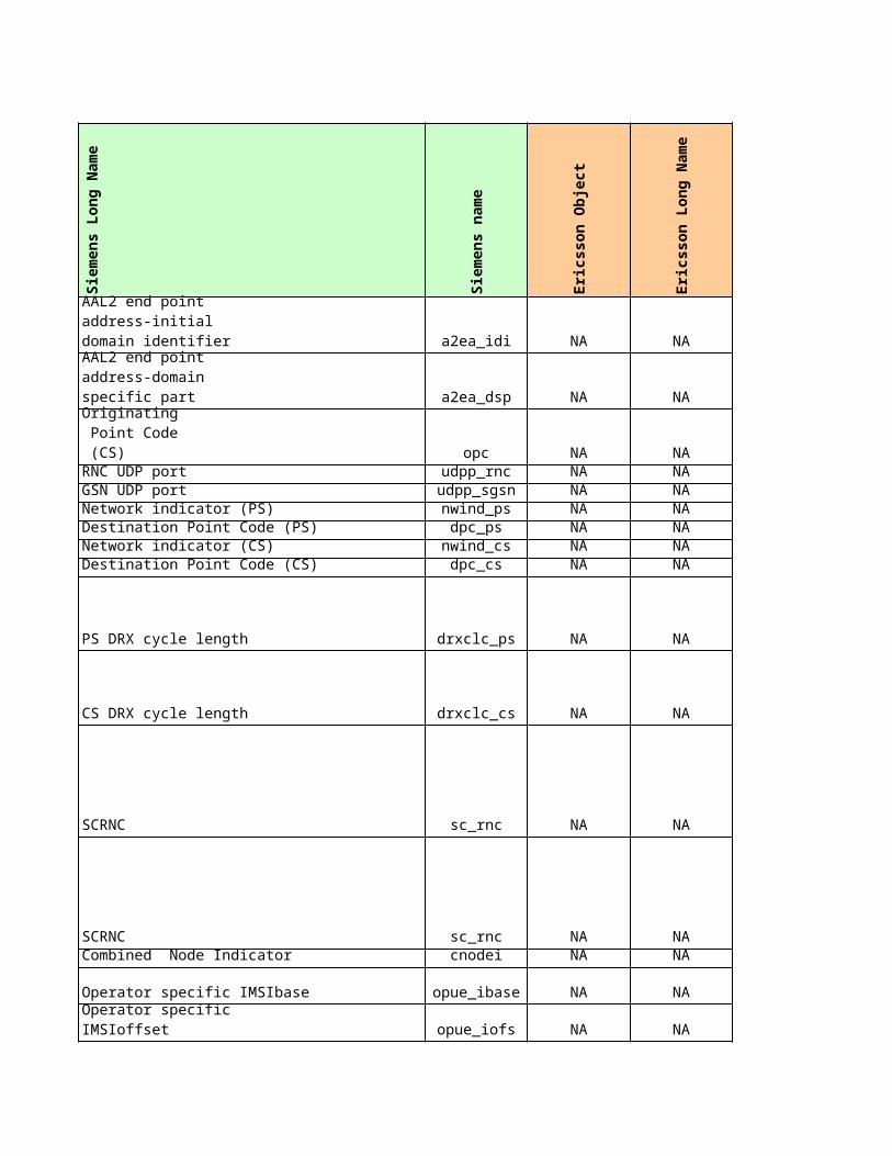
a2ea_idi NA NA NA
a2ea_dsp NA NA NA
opc NA NA NARNC UDP port udpp_rnc NA NA NAGSN UDP port udpp_sgsn NA NA NANetwork indicator (PS) nwind_ps NA NA NADestination Point Code (PS) dpc_ps NA NA NANetwork indicator (CS) nwind_cs NA NA NADestination Point Code (CS) dpc_cs NA NA NA
PS DRX cycle length drxclc_ps NA NA NA
CS DRX cycle length drxclc_cs NA NA NA
SCRNC sc_rnc NA NA NA
SCRNC sc_rnc NA NA NACombined Node Indicator cnodei NA NA NA
Operator specific IMSIbase opue_ibase NA NA NA
opue_iofs NA NA NA
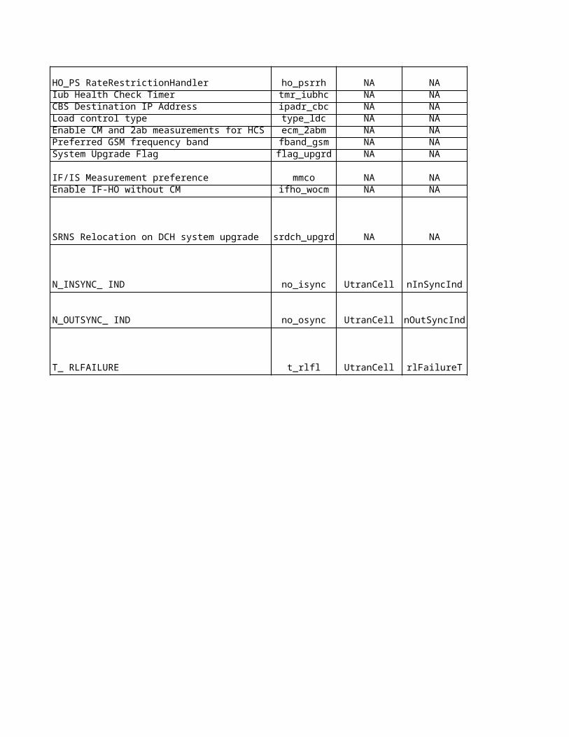
HO_PS RateRestrictionHandler ho_psrrh NA NA NAIub Health Check Timer tmr_iubhc NA NA NACBS Destination IP Address ipadr_cbc NA NA NA
AAL2 end point address-initial domain identifier
AAL2 end point address-domain specific part
Originating Point Code (CS)
Operator specificIMSIoffset
Load control type type_ldc NA NA NAEnable CM and 2ab measurements for HCS ecm_2abm NA NA NAPreferred GSM frequency band fband_gsm NA NA NASystem Upgrade Flag flag_upgrd NA NA NA
IF/IS Measurement preference mmco NA NA NAEnable IF-HO without CM ifho_wocm NA NA NA
SRNS Relocation on DCH system upgrade srdch_upgrd NA NA NA
N_INSYNC_ IND no_isync UtranCell nInSyncInd nInSyncInd
N_OUTSYNC_ IND no_osync UtranCell nOutSyncInd nOutSyncInd
T_ RLFAILURE t_rlfl UtranCell rlFailureT rlFailureT
No
kia
pro
po
se
d
Sie
me
ns
cu
rre
nt
Eri
cs
so
n c
urr
en
t
Ag
ree
d
No
kia
Un
it
Sie
me
ns
Un
it
Eri
cs
so
n U
nit
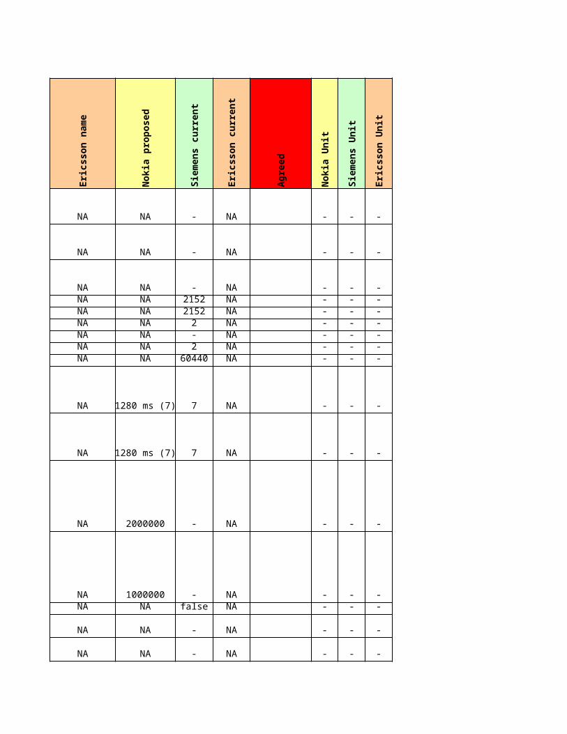
NA - NA - - -
NA - NA - - -
NA - NA - - -NA 2152 NA - - -NA 2152 NA - - -NA 2 NA - - -NA - NA - - -NA 2 NA - - -NA 60440 NA - - -
1280 ms (7) 7 NA - - -
1280 ms (7) 7 NA - - -
2000000 - NA - - -
1000000 - NA - - -NA false NA - - -
NA - NA - - -
NA - NA - - -
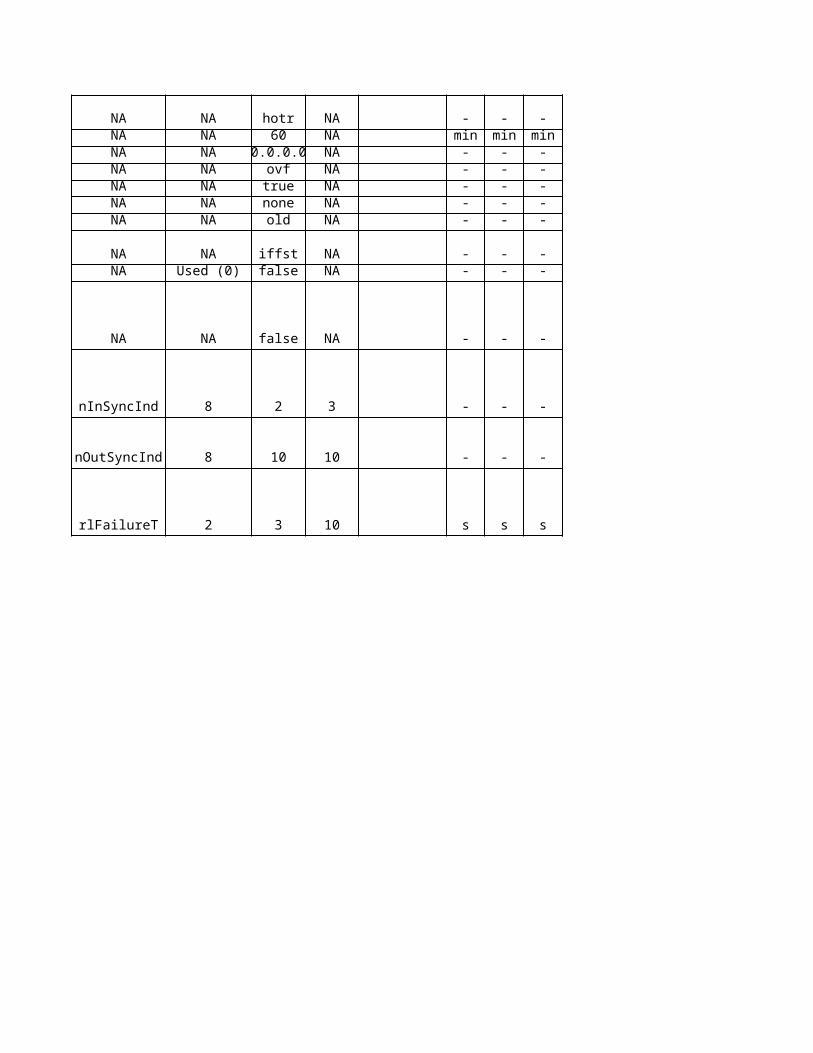
NA hotr NA - - -NA 60 NA min min minNA 0.0.0.0 NA - - -
NA ovf NA - - -NA true NA - - -NA none NA - - -NA old NA - - -
NA iffst NA - - -Used (0) false NA - - -
NA false NA - - -
8 2 3 - - -
8 10 10 - - -
2 3 10 s s s

No
kia
De
sc
rip
tio
n
NA
NA
NANANANANANANA
NA
NA
NA
NANANA
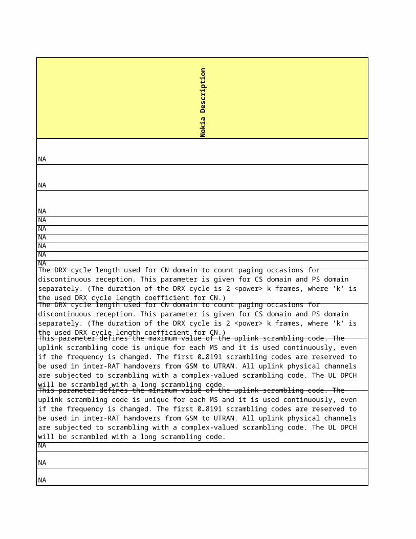
The DRX cycle length used for CN domain to count paging occasions for discontinuous reception. This parameter is given for CS domain and PS domain separately. (The duration of the DRX cycle is 2 <power> k frames, where 'k' is the used DRX cycle length coefficient for CN.)
The DRX cycle length used for CN domain to count paging occasions for discontinuous reception. This parameter is given for CS domain and PS domain separately. (The duration of the DRX cycle is 2 <power> k frames, where 'k' is the used DRX cycle length coefficient for CN.)
This parameter defines the maximum value of the uplink scrambling code. The uplink scrambling code is unique for each MS and it is used continuously, even if the frequency is changed. The first 0…8191 scrambling codes are reserved to be used in inter-RAT handovers from GSM to UTRAN. All uplink physical channels are subjected to scrambling with a complex-valued scrambling code. The UL DPCH will be scrambled with a long scrambling code.
This parameter defines the minimum value of the uplink scrambling code. The uplink scrambling code is unique for each MS and it is used continuously, even if the frequency is changed. The first 0…8191 scrambling codes are reserved to be used in inter-RAT handovers from GSM to UTRAN. All uplink physical channels are subjected to scrambling with a complex-valued scrambling code. The UL DPCH will be scrambled with a long scrambling code.
NANANANA
NAThis parameter defines whether or not compressed mode is used on the system level.
NA
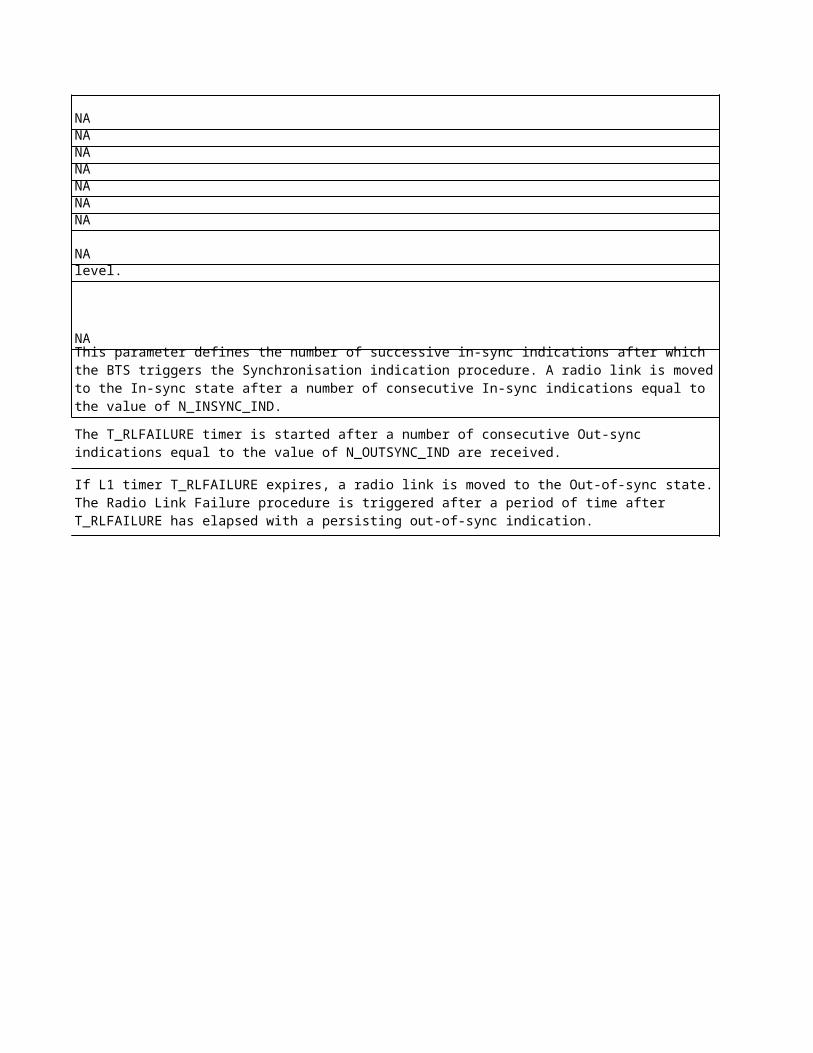
This parameter defines the number of successive in-sync indications after which the BTS triggers the Synchronisation indication procedure. A radio link is moved to the In-sync state after a number of consecutive In-sync indications equal to the value of N_INSYNC_IND.
The T_RLFAILURE timer is started after a number of consecutive Out-sync indications equal to the value of N_OUTSYNC_IND are received.
If L1 timer T_RLFAILURE expires, a radio link is moved to the Out-of-sync state. The Radio Link Failure procedure is triggered after a period of time after T_RLFAILURE has elapsed with a persisting out-of-sync indication.
Sie
me
ns
De
sc
rip
tio
n
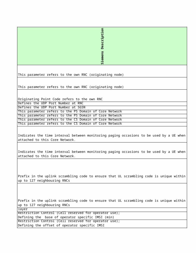
This parameter refers to the own RNC (originating node)
This parameter refers to the own RNC (originating node)
Originating Point Code refers to the own RNCDefines the UDP Port Number at RNCDefines the UDP Port Number at SGSNThis parameter refers to the PS Domain of Core NetworkThis parameter refers to the PS Domain of Core NetworkThis parameter refers to the CS Domain of Core NetworkThis parameter refers to the CS Domain of Core Network
Indicates whether the Core Network combines the PS and CS domain from transport network layer
Specifies the period for the Health Check procedureIP address of Cell Broadcast Center
Indicates the time interval between monitoring paging occasions to be used by a UE when attached to this Core Network.
Indicates the time interval between monitoring paging occasions to be used by a UE when attached to this Core Network.
Prefix in the uplink scrambling code to ensure that UL scrambling code is unique within up to 127 neighbouring RNCs
Prefix in the uplink scrambling code to ensure that UL scrambling code is unique within up to 127 neighbouring RNCs
Restriction Control (Cell reserved for operator use);Defining the base of operator specific IMSI (min)
Restriction Control (Cell reserved for operator use);Defining the offset of operator specific IMSI
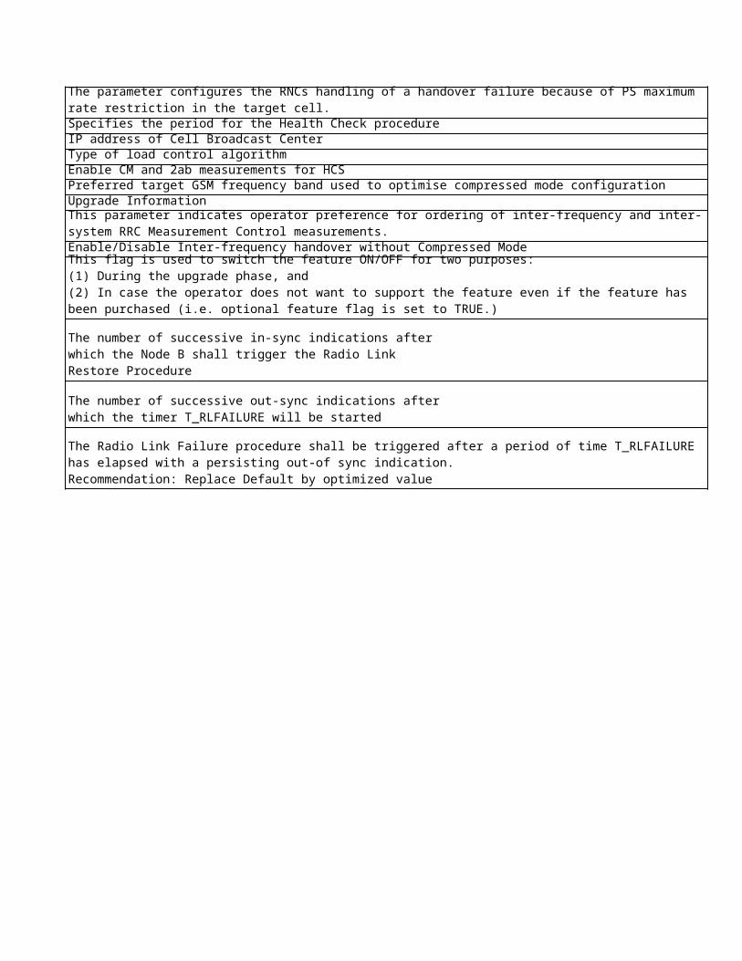
The parameter configures the RNCs handling of a handover failure because of PS maximum rate restriction in the target cell.
Type of load control algorithmEnable CM and 2ab measurements for HCSPreferred target GSM frequency band used to optimise compressed mode configurationUpgrade Information
Enable/Disable Inter-frequency handover without Compressed Mode
This parameter indicates operator preference for ordering of inter-frequency and inter-system RRC Measurement Control measurements.
This flag is used to switch the feature ON/OFF for two purposes:(1) During the upgrade phase, and (2) In case the operator does not want to support the feature even if the feature has been purchased (i.e. optional feature flag is set to TRUE.)
The number of successive in-sync indications after which the Node B shall trigger the Radio Link Restore Procedure
The number of successive out-sync indications after which the timer T_RLFAILURE will be started
The Radio Link Failure procedure shall be triggered after a period of time T_RLFAILURE has elapsed with a persisting out-of sync indication.Recommendation: Replace Default by optimized value
Eri
cs
so
n D
es
cri
pti
on
NA
NA
NANANANANANANA
NA
NA
NA
NANA
NA
NA
NANANA
NANANANA
NANA
NA
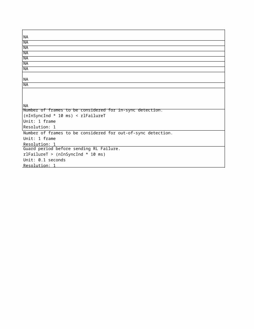
Number of frames to be considered for in-sync detection.(nInSyncInd * 10 ms) < rlFailureTUnit: 1 frameResolution: 1
Number of frames to be considered for out-of-sync detection. Unit: 1 frameResolution: 1
Guard period before sending RL Failure. rlFailureT > (nInSyncInd * 10 ms)Unit: 0.1 secondsResolution: 1
No
kia
Ob
jec
t
No
kia
Lo
ng
Na
me
No
kia
na
me
NA NA NANA NA NANA NA NANA NA NANA NA NANA NA NANA NA NANA NA NA
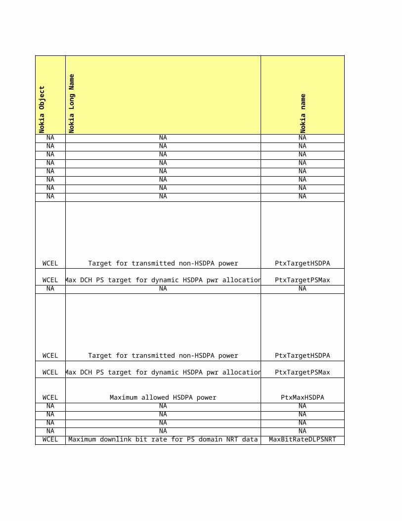
WCEL Target for transmitted non-HSDPA power PtxTargetHSDPA
WCEL Max DCH PS target for dynamic HSDPA pwr allocation PtxTargetPSMaxNA NA NA
WCEL Target for transmitted non-HSDPA power PtxTargetHSDPA
WCEL Max DCH PS target for dynamic HSDPA pwr allocation PtxTargetPSMax
WCEL Maximum allowed HSDPA power PtxMaxHSDPANA NA NANA NA NANA NA NANA NA NA
WCEL Maximum downlink bit rate for PS domain NRT data MaxBitRateDLPSNRT
NA NA NA
NA NA NANA NA NANA NA NA
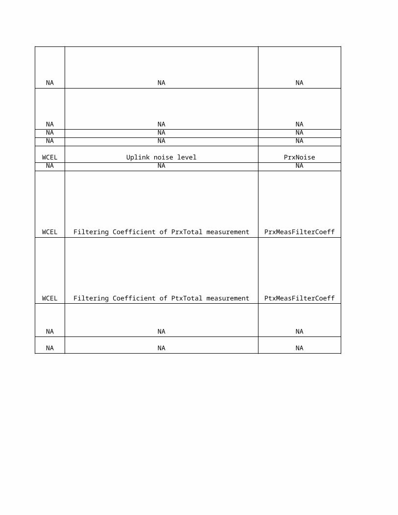
WCEL Uplink noise level PrxNoiseNA NA NA
WCEL Filtering Coefficient of PrxTotal measurement PrxMeasFilterCoeff
WCEL Filtering Coefficient of PtxTotal measurement PtxMeasFilterCoeff
NA NA NA
NA NA NA
Sie
me
ns
Ob
jec
t
Sie
me
ns
Lo
ng
Na
me
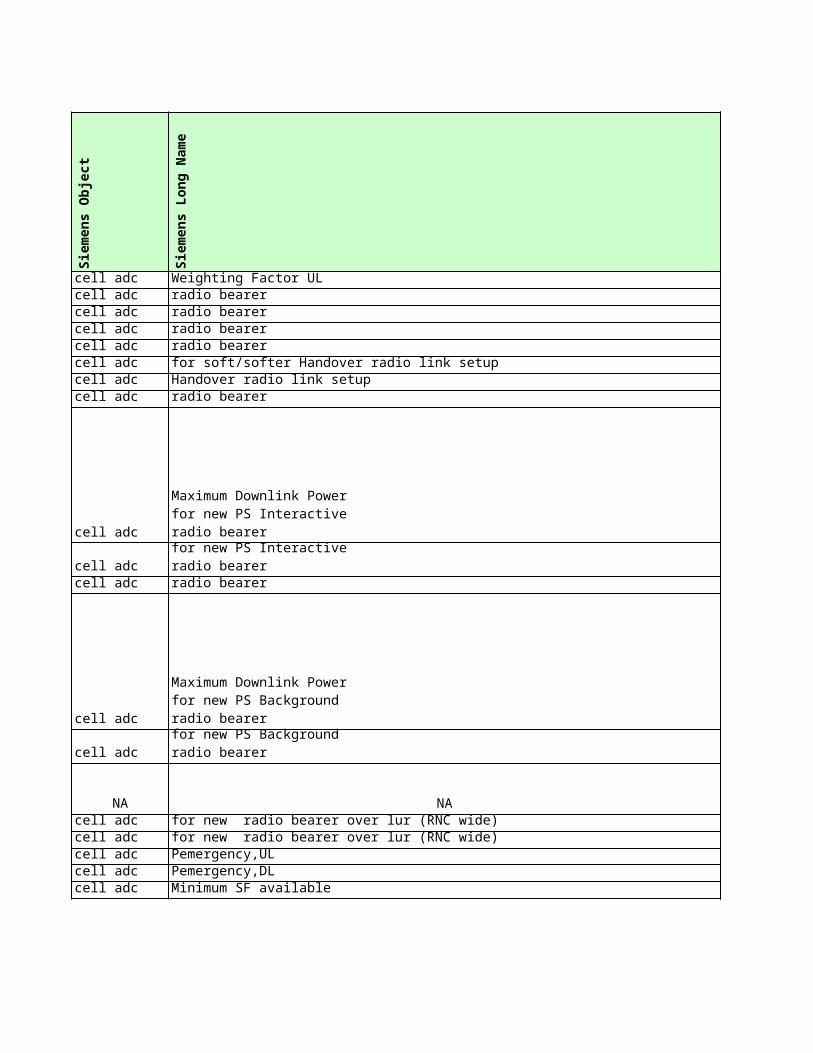
cell adc Weighting Factor ULcell adccell adccell adccell adccell adccell adccell adc
cell adc
cell adccell adc
cell adc
cell adc
NA NAcell adccell adccell adccell adccell adc Minimum SF available
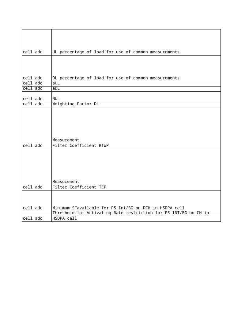
cell adc UL percentage of load for use of common measurements
radio bearer radio bearer radio bearer radio bearer for soft/softer Handover radio link setup Handover radio link setupradio bearer
Maximum Downlink Powerfor new PS Interactive radio bearer Maximum Downlink Powerfor new PS Interactive radio bearer radio bearer
Maximum Downlink Powerfor new PS Background radio bearer Maximum Downlink Powerfor new PS Background radio bearer
for new radio bearer over lur (RNC wide)for new radio bearer over lur (RNC wide)Pemergency,ULPemergency,DL
cell adc DL percentage of load for use of common measurementscell adc aULcell adc aDL
cell adc NULcell adc Weighting Factor DL
cell adc
cell adc
cell adc Minimum SFavailable for PS Int/BG on DCH in HSDPA cell
cell adc Threshold for Activating Rate restriction for PS INT/BG on CH in HSDPA cell
Measurement Filter Coefficient RTWP
Measurement Filter Coefficient TCP
Sie
me
ns
na
me
Eri
cs
so
n O
bje
ct
Eri
cs
so
n L
on
g N
am
e
Eri
cs
so
n n
am
e
No
kia
pro
po
se
d
Sie
me
ns
cu
rre
nt
Eri
cs
so
n c
urr
en
t
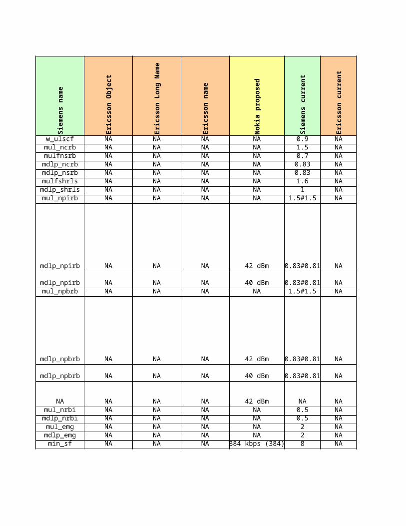
w_ulscf NA NA NA NA 0.9 NAmul_ncrb NA NA NA NA 1.5 NAmulfnsrb NA NA NA NA 0.7 NA
mdlp_ncrb NA NA NA NA 0.83 NAmdlp_nsrb NA NA NA NA 0.83 NAmulfshrls NA NA NA NA 1.6 NA
mdlp_shrls NA NA NA NA 1 NAmul_npirb NA NA NA NA 1.5#1.5 NA
mdlp_npirb NA NA NA 42 dBm 0.83#0.81 NA
mdlp_npirb NA NA NA 40 dBm 0.83#0.81 NAmul_npbrb NA NA NA NA 1.5#1.5 NA
mdlp_npbrb NA NA NA 42 dBm 0.83#0.81 NA
mdlp_npbrb NA NA NA 40 dBm 0.83#0.81 NA
NA NA NA NA 42 dBm NA NAmul_nrbi NA NA NA NA 0.5 NA
mdlp_nrbi NA NA NA NA 0.5 NAmul_emg NA NA NA NA 2 NA
mdlp_emg NA NA NA NA 2 NAmin_sf NA NA NA 384 kbps (384) 8 NA
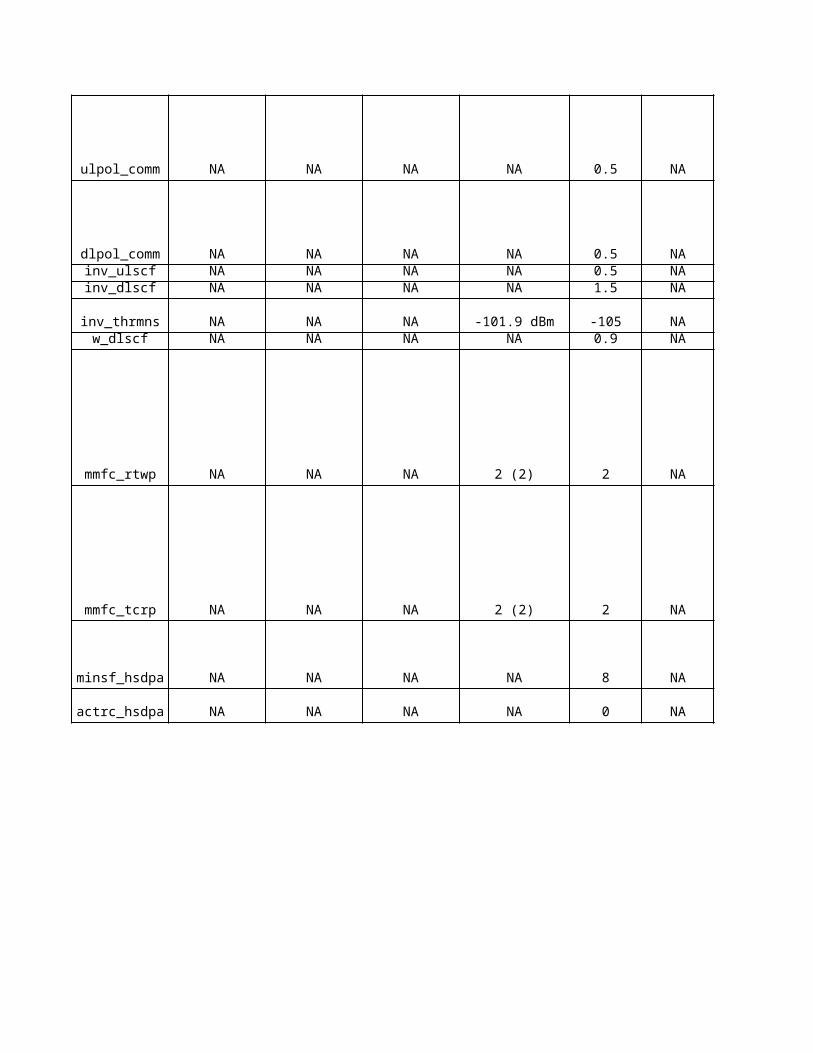
ulpol_comm NA NA NA NA 0.5 NA
dlpol_comm NA NA NA NA 0.5 NAinv_ulscf NA NA NA NA 0.5 NAinv_dlscf NA NA NA NA 1.5 NA
inv_thrmns NA NA NA -101.9 dBm -105 NAw_dlscf NA NA NA NA 0.9 NA
mmfc_rtwp NA NA NA 2 (2) 2 NA
mmfc_tcrp NA NA NA 2 (2) 2 NA
minsf_hsdpa NA NA NA NA 8 NA
actrc_hsdpa NA NA NA NA 0 NA
Ag
ree
d
No
kia
Un
it
Sie
me
ns
Un
it
Eri
cs
so
n U
nit
- - -- - -- - -- - -- - -- - -- - -- - -
- - -
- - -- - -
- - -
- - -
dBm - -- - -- - -- - -- - -- -
- -
- -- -- -
dBm dBm- -
- -
- -
- -
UE UE
No
kia
De
sc
rip
tio
n
NANANANANANANANA
NA
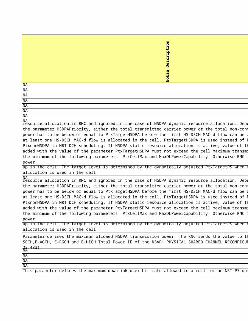
NANANANAThis parameter defines the maximum downlink user bit rate allowed in a cell for an NRT PS domain RAB.
NA
Parameter defines the target scheduling threshold for HSDPA power allocation. It is applicable to the HSDPA static resource allocation in RNC and ignored in the case of HSDPA dynamic resource allocation. Depending on the setting of the parameter HSDPAPriority, either the total transmitted carrier power or the total non-controllable transmitted power has to be below or equal to PtxTargetHSDPA before the first HS-DSCH MAC-d flow can be allocated in the cell. If at least one HS-DSCH MAC-d flow is allocated in the cell, PtxTargetHSDPA is used instead of PtxTarget as a target of PtxnonHSDPA in NRT DCH scheduling. If HSDPA static resource allocation is active, value of the parameter PtxMaxHSDPA added with the value of the parameter PtxTargetHSDPA must not exceed the cell maximum transmission power defined by the minimum of the following parameters: PtxCellMax and MaxDLPowerCapability. Otherwise RNC internally limits HSDPA power.
This parameter defines the maximum allowed target level for DCH packet scheduling when one or more MAC-d flows is set up in the cell. The target level is determined by the dynamically adjusted PtxTargetPS when HSDPA dynamic resource allocation is used in the cell.
Parameter defines the maximum allowed HSDPA transmission power. The RNC sends the value to the BTS in HS-PDSCH, HS-SCCH,E-AGCH, E-RGCH and E-HICH Total Power IE of the NBAP: PHYSICAL SHARED CHANNEL RECONFIGURATION REQUEST message (TS 25.433).
NANANA
NA
NA
NA
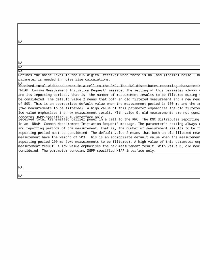
Defines the noise level in the BTS digital receiver when there is no load (thermal noise + noise figure). This parameter is needed in noise rise calculations.
This parameter defines how measurement values should be filtered before Node B reports the common measurement of the received total wideband power in a cell to the RNC. The RNC distributes reporting characteristics to Node B in an 'NBAP: Common Measurement Initiation Request' message. The setting of this parameter always depends on the measurement and its reporting periods, that is, the number of measurement results to be filtered during the reporting period must be considered. The default value 2 means that both an old filtered measurement and a new measurement have the weight of 50%. This is an appropriate default value when the measurement period is 100 ms and the reporting period 200 ms (two measurements to be filtered). A high value of this parameter emphasises the old filtered measurement result. A low value emphasises the new measurement result. With value 0, old measurements are not considered. This parameter concerns 3GPP-specified NBAP-interface only.
This parameter defines how measurement values should be filtered before Node B reports the common measurement of the received total transmitted carrier power in a cell to the RNC. The RNC distributes reporting characteristics to Node B in an 'NBAP: Common Measurement Initiation Request' message. The parameter's setting always depends on the measurement and reporting periods of the measurement; that is, the number of measurement results to be filtered during the reporting period must be considered. The default value 2 means that both an old filtered measurement and a new measurement have the weight of 50%. This is an appropriate default value when the measurement period is 100 ms and the reporting period 200 ms (two measurements to be filtered). A high value of this parameter emphasises the old filtered measurement result. A low value emphasises the new measurement result. With value 0, old measurements are not considered. The parameter concerns 3GPP-specified NBAP-interface only.
Sie
me
ns
De
sc
rip
tio
n
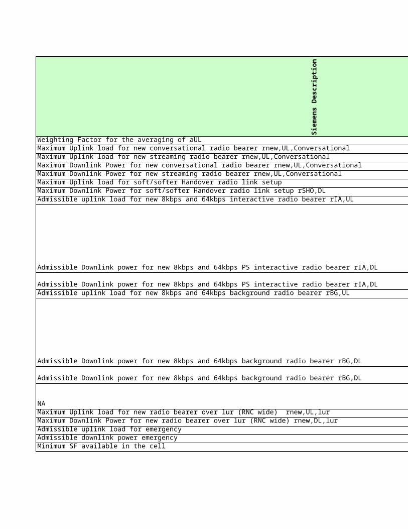
Weighting Factor for the averaging of aULMaximum Uplink load for new conversational radio bearer rnew,UL,ConversationalMaximum Uplink load for new streaming radio bearer rnew,UL,ConversationalMaximum Downlink Power for new conversational radio bearer rnew,UL,ConversationalMaximum Downlink Power for new streaming radio bearer rnew,UL,ConversationalMaximum Uplink load for soft/softer Handover radio link setupMaximum Downlink Power for soft/softer Handover radio link setup rSHO,DLAdmissible uplink load for new 8kbps and 64kbps interactive radio bearer rIA,UL
Admissible Downlink power for new 8kbps and 64kbps PS interactive radio bearer rIA,DL
Admissible Downlink power for new 8kbps and 64kbps PS interactive radio bearer rIA,DLAdmissible uplink load for new 8kbps and 64kbps background radio bearer rBG,UL
Admissible Downlink power for new 8kbps and 64kbps background radio bearer rBG,DL
Admissible Downlink power for new 8kbps and 64kbps background radio bearer rBG,DL
NAMaximum Uplink load for new radio bearer over lur (RNC wide) rnew,UL,lurMaximum Downlink Power for new radio bearer over lur (RNC wide) rnew,DL,lurAdmissible uplink load for emergency Admissible downlink power emergency Minimum SF available in the cell
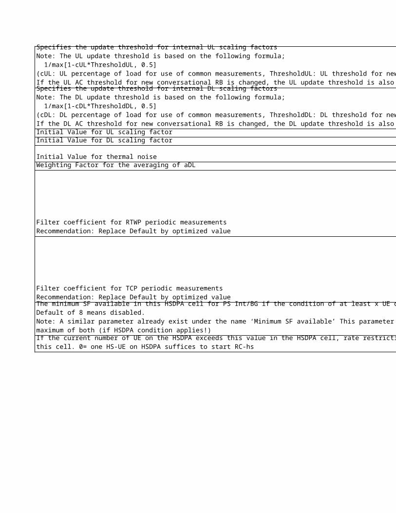
Specifies the update threshold for internal UL scaling factorsNote: The UL update threshold is based on the following formula; 1/max[1-cUL*ThresholdUL, 0.5] (cUL: UL percentage of load for use of common measurements, ThresholdUL: UL threshold for new conversational RB)If the UL AC threshold for new conversational RB is changed, the UL update threshold is also changed.
Initial Value for UL scaling factorInitial Value for DL scaling factor
Initial Value for thermal noiseWeighting Factor for the averaging of aDL
Specifies the update threshold for internal DL scaling factorsNote: The DL update threshold is based on the following formula; 1/max[1-cDL*ThresholdDL, 0.5] (cDL: DL percentage of load for use of common measurements, ThresholdDL: DL threshold for new conversational RB)If the DL AC threshold for new conversational RB is changed, the DL update threshold is also changed.
Filter coefficient for RTWP periodic measurementsRecommendation: Replace Default by optimized value
Filter coefficient for TCP periodic measurementsRecommendation: Replace Default by optimized value
The minimum SF available in this HSDPA cell for PS Int/BG if the condition of at least x UE on HSDPA is fulfilled.Default of 8 means disabled.Note: A similar parameter already exist under the name ‘Minimum SF available’ This parameter is still needed since AC will determine the maximum of both (if HSDPA condition applies!)
If the current number of UE on the HSDPA exceeds this value in the HSDPA cell, rate restriction for PS Int/BG on DPCH will be applied in this cell. 0= one HS-UE on HSDPA suffices to start RC-hs
Eri
cs
so
n D
es
cri
pti
on
NANANANANANANANA
NA
NANA
NA
NA
NANANANANANA
NA
NANANA
NANA
NA
NA
NA
NA
No
kia
Ob
jec
t
No
kia
Lo
ng
Na
me
No
kia
na
me
Sie
me
ns
Ob
jec
t
NA NA NA cell cctl
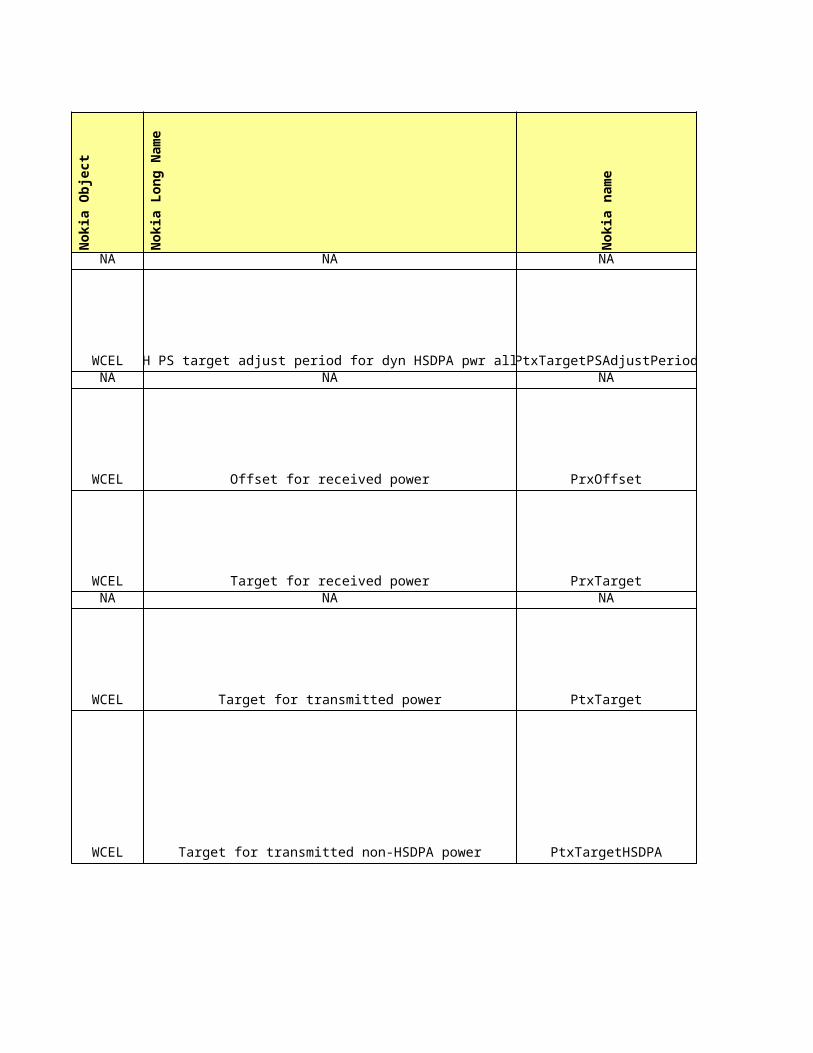
WCEL DCH PS target adjust period for dyn HSDPA pwr alloc PtxTargetPSAdjustPeriod cell cctlNA NA NA cell cctl
WCEL Offset for received power PrxOffset cell cctl
WCEL Target for received power PrxTarget cell cctlNA NA NA cell cctl
WCEL Target for transmitted power PtxTarget cell cctl
WCEL Target for transmitted non-HSDPA power PtxTargetHSDPA cell cctl
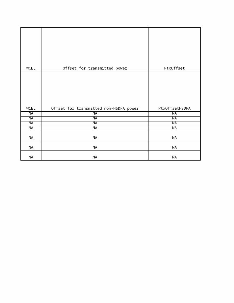
WCEL Offset for transmitted power PtxOffset cell cctl
WCEL Offset for transmitted non-HSDPA power PtxOffsetHSDPA cell cctlNA NA NA cell cctlNA NA NA cell cctlNA NA NA cell cctlNA NA NA cell cctl
NA NA NA cell cctl
NA NA NA cell cctl
NA NA NA cell cctl
Sie
me
ns
Lo
ng
Na
me
Sie
me
ns
na
me
Eri
cs
so
n O
bje
ct
Eri
cs
so
n L
on
g N
am
e
Eri
cs
so
n n
am
e
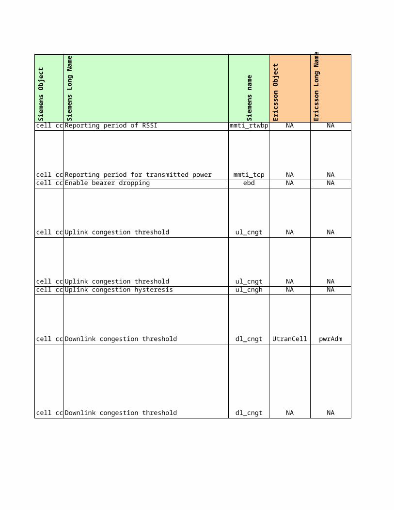
Reporting period of RSSI mmti_rtwbp NA NA NA
Reporting period for transmitted power mmti_tcp NA NA NAEnable bearer dropping ebd NA NA NA
Uplink congestion threshold ul_cngt NA NA NA
Uplink congestion threshold ul_cngt NA NA NAUplink congestion hysteresis ul_cngh NA NA NA
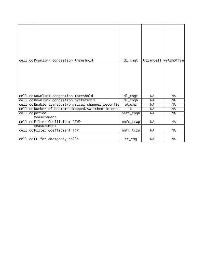
Downlink congestion threshold dl_cngt UtranCell pwrAdm pwrAdm
Downlink congestion threshold dl_cngt NA NA NA
Downlink congestion threshold dl_cngt UtranCell pwrAdmOffsetpwrAdmOffset
Downlink congestion threshold dl_cngt NA NA NADownlink congestion hysteresis dl_cngh NA NA NAEnable transport/physical channel reconfiguration etpchr NA NA NANumber of bearers dropped/switched in one step k NA NA NA
peri_cngh NA NA NA
mmfc_rtwp NA NA NA
mmfc_tcrp NA NA NA
CC for emergency calls cc_emg NA NA NA
period
Measurement Filter Coefficient RTWP
Measurement Filter Coefficient TCP
No
kia
pro
po
se
d
Sie
me
ns
cu
rre
nt
Eri
cs
so
n c
urr
en
t
Ag
ree
d
No
kia
Un
it
Sie
me
ns
Un
it
Eri
cs
so
n U
nit
NA 10 NA s s
10 10 NA s sNA dis NA - -
6 60 NA dB dB
30 60 NA dB dBNA 2 NA dB dB
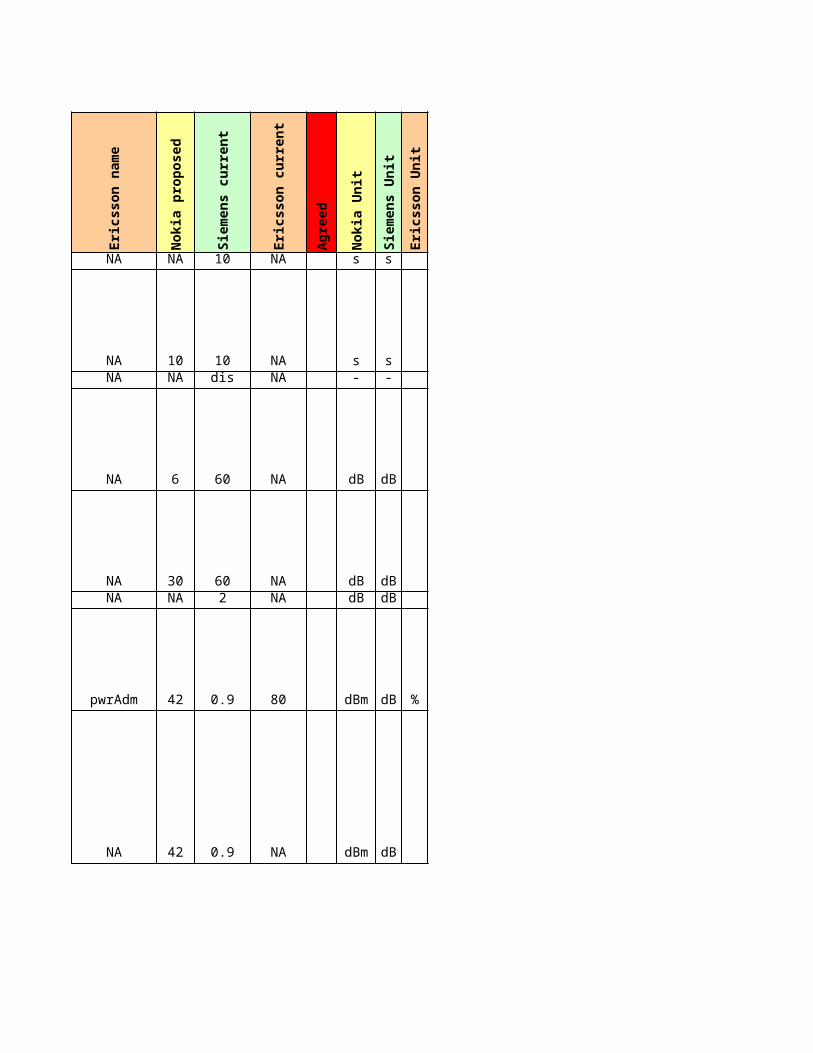
42 0.9 80 dBm dB %
42 0.9 NA dBm dB
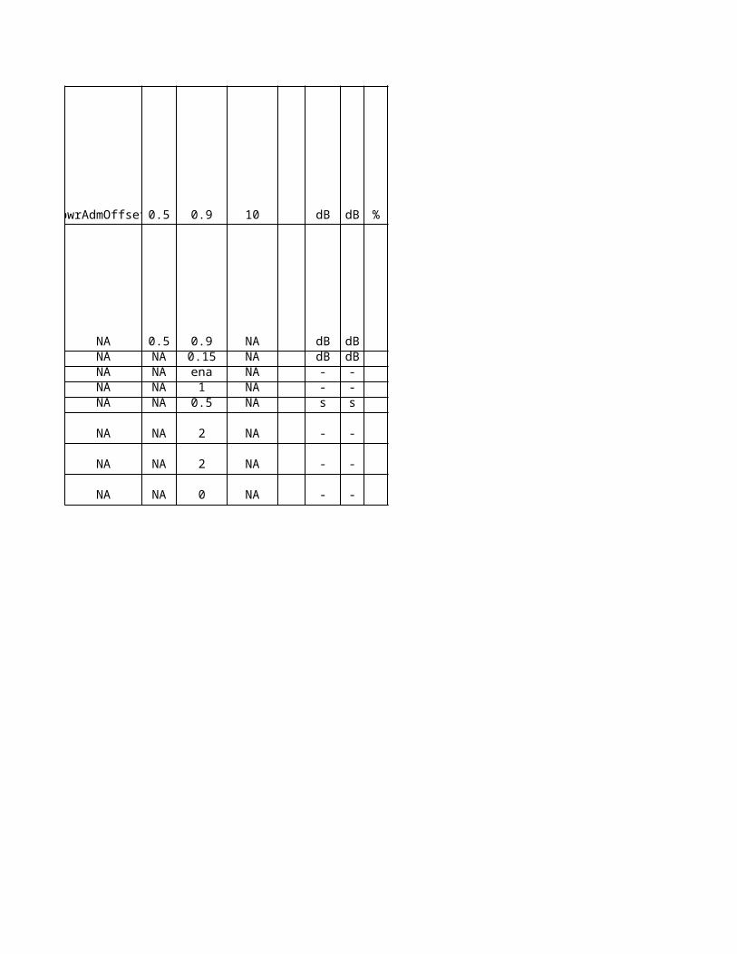
0.5 0.9 10 dB dB %
0.5 0.9 NA dB dBNA 0.15 NA dB dBNA ena NA - -NA 1 NA - -NA 0.5 NA s s
NA 2 NA - -
NA 2 NA - -
NA 0 NA - -
No
kia
De
sc
rip
tio
n
NA
NA
NA
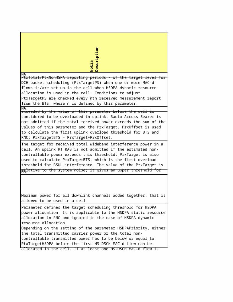
This parameter defines the adjustment period - in terms of PtxTotal/PtxNonHSPA reporting periods - of the target level for DCH packet scheduling (PtxTargetPS) when one or more MAC-d flows is/are set up in the cell when HSDPA dynamic resource allocation is used in the cell. Conditions to adjust PtxTargetPS are checked every nth received measurement report from the BTS, where n is defined by this parameter.
The target value of the total received power (PrxTarget) can be exceeded by the value of this parameter before the cell is considered to be overloaded in uplink. Radio Access Bearer is not admitted if the total received power exceeds the sum of the values of this parameter and the PrxTarget. PrxOffset is used to calculate the first uplink overload threshold for BTS and RNC: PrxTargetBTS = PrxTarget+PrxOffset.
The target for received total wideband interference power in a cell. An uplink RT RAB is not admitted if the estimated non-controllable power exceeds this threshold. PrxTarget is also used to calculate PrxTargetBTS, which is the first overload threshold for BSUL interference. The value of the PrxTarget is relative to the system noise; it gives an upper threshold for the noise rise: the ratio of the total received uplink power to system noise.
Maximum power for all downlink channels added together, that is allowed to be used in a cell
Parameter defines the target scheduling threshold for HSDPA power allocation. It is applicable to the HSDPA static resource allocation in RNC and ignored in the case of HSDPA dynamic resource allocation. Depending on the setting of the parameter HSDPAPriority, either the total transmitted carrier power or the total non-controllable transmitted power has to be below or equal to PtxTargetHSDPA before the first HS-DSCH MAC-d flow can be allocated in the cell. If at least one HS-DSCH MAC-d flow is allocated in the cell, PtxTargetHSDPA is used instead of PtxTarget as a target of PtxnonHSDPA in NRT DCH scheduling.
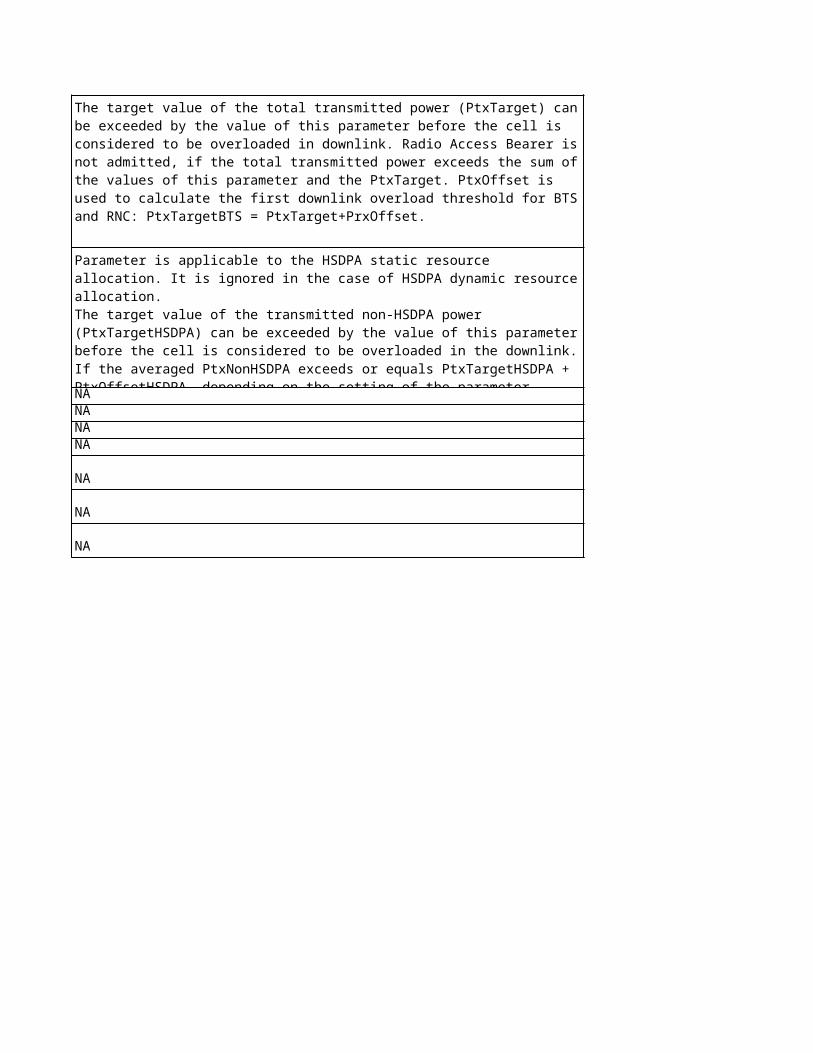
The target value of the total transmitted power (PtxTarget) can be exceeded by the value of this parameter before the cell is considered to be overloaded in downlink. Radio Access Bearer is not admitted, if the total transmitted power exceeds the sum of the values of this parameter and the PtxTarget. PtxOffset is used to calculate the first downlink overload threshold for BTS and RNC: PtxTargetBTS = PtxTarget+PrxOffset.
NANANANA
NA
NA
NA
Parameter is applicable to the HSDPA static resource allocation. It is ignored in the case of HSDPA dynamic resource allocation. The target value of the transmitted non-HSDPA power (PtxTargetHSDPA) can be exceeded by the value of this parameter before the cell is considered to be overloaded in the downlink. If the averaged PtxNonHSDPA exceeds or equals PtxTargetHSDPA + PtxOffsetHSDPA, depending on the setting of the parameter HSDPAPriority, overload control actions targeted either to HS-DSCH MAC-d flows or NRT DCHs are started.
Sie
me
ns
De
sc
rip
tio
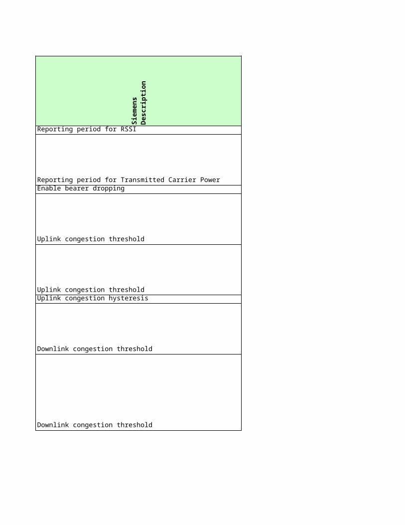
nReporting period for RSSI
Reporting period for Transmitted Carrier PowerEnable bearer dropping
Uplink congestion threshold
Uplink congestion thresholdUplink congestion hysteresis
Downlink congestion threshold
Downlink congestion threshold
Downlink congestion threshold
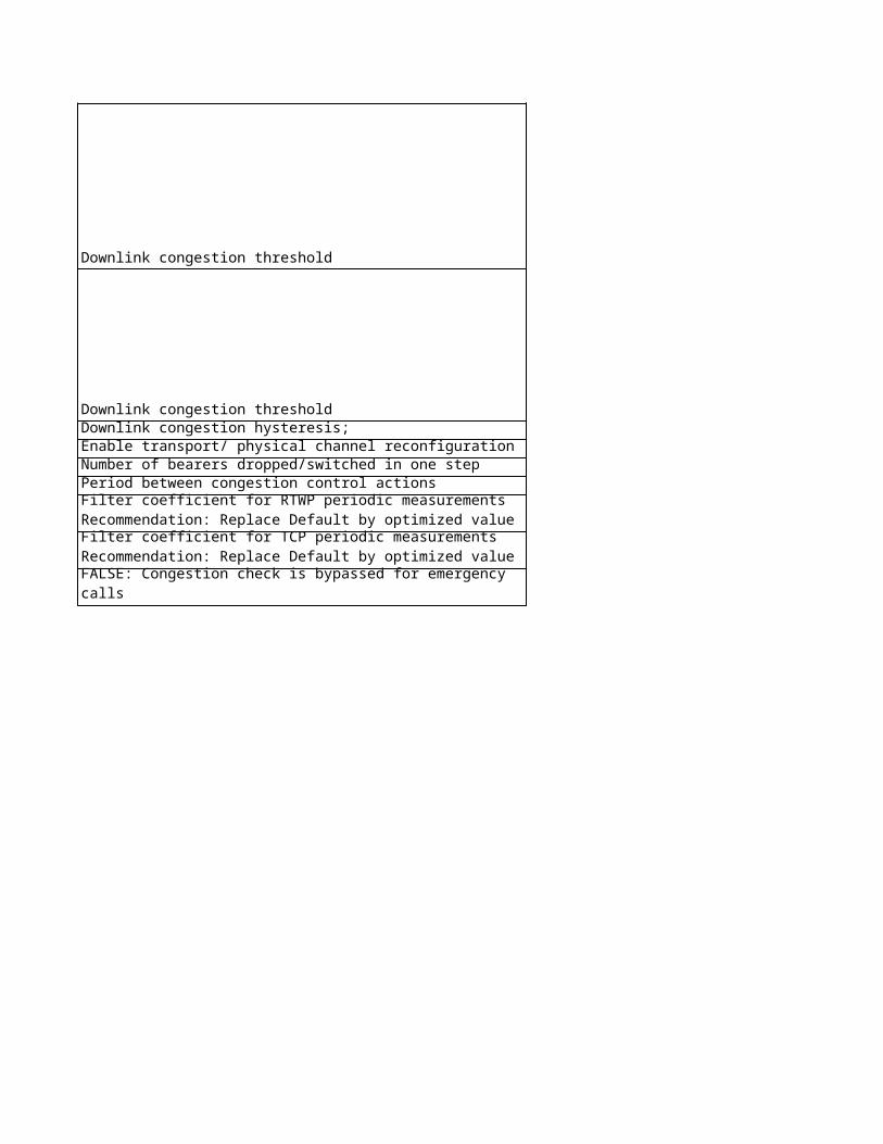
Downlink congestion thresholdDownlink congestion hysteresis;Enable transport/ physical channel reconfigurationNumber of bearers dropped/switched in one stepPeriod between congestion control actions
Filter coefficient for RTWP periodic measurementsRecommendation: Replace Default by optimized value
Filter coefficient for TCP periodic measurementsRecommendation: Replace Default by optimized value
TRUE: Congestion check is performed for emergency callsFALSE: Congestion check is bypassed for emergency calls
Eri
cs
so
n D
es
cri
pti
on
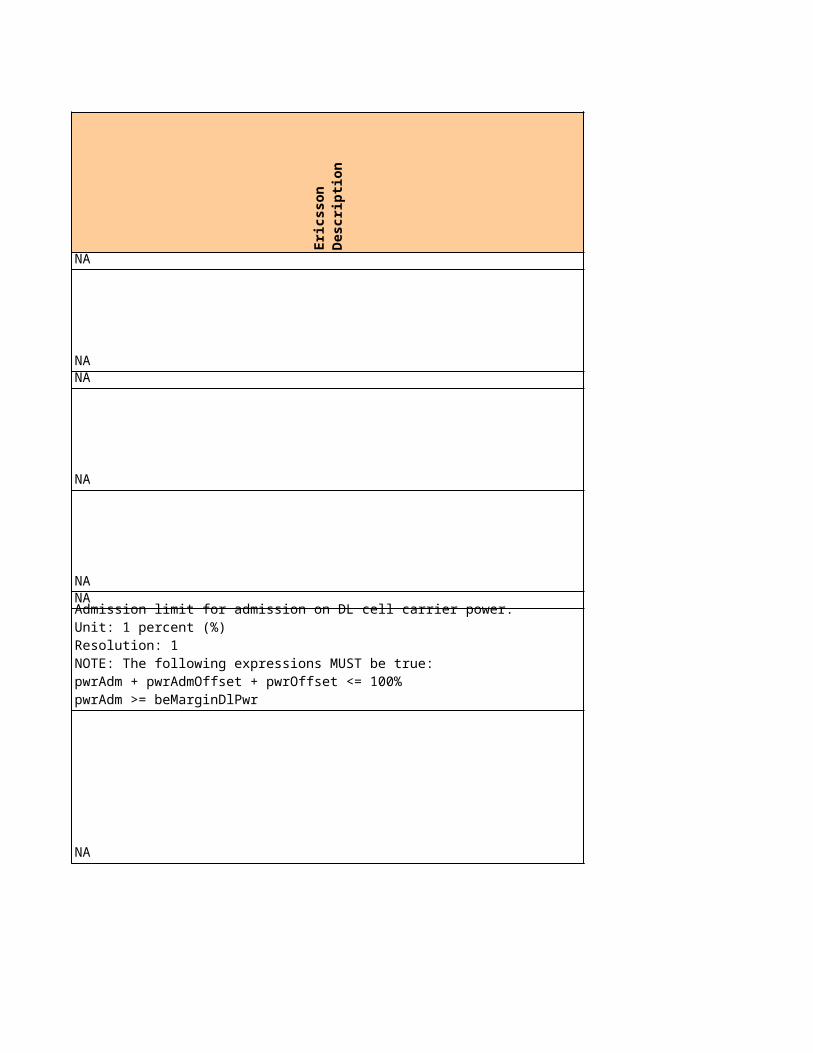
NA
NANA
NA
NANA
NA
Admission limit for admission on DL cell carrier power.Unit: 1 percent (%)Resolution: 1NOTE: The following expressions MUST be true:pwrAdm + pwrAdmOffset + pwrOffset <= 100%pwrAdm >= beMarginDlPwr
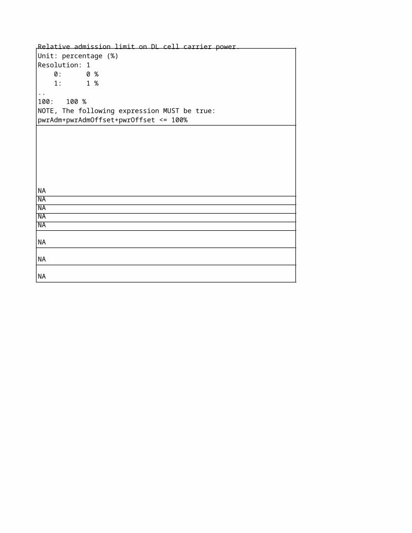
Relative admission limit on DL cell carrier power.Unit: percentage (%)Resolution: 1 0: 0 % 1: 1 %..100: 100 %NOTE, The following expression MUST be true:pwrAdm+pwrAdmOffset+pwrOffset <= 100%
NANANANANA
NA
NA
NA
No
kia
Ob
jec
t
No
kia
Lo
ng
Na
me
No
kia
na
me
NA NA NANA NA NANA NA NA
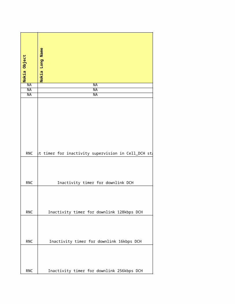
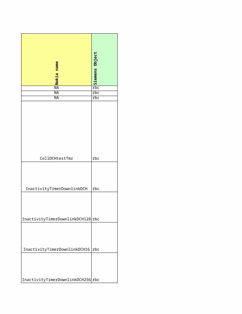
RNC Test timer for inactivity supervision in Cell_DCH state CellDCHtestTmr
RNC Inactivity timer for downlink DCH InactivityTimerDownlinkDCH
RNC Inactivity timer for downlink 128kbps DCH InactivityTimerDownlinkDCH128
RNC Inactivity timer for downlink 16kbps DCH InactivityTimerDownlinkDCH16
RNC Inactivity timer for downlink 256kbps DCH InactivityTimerDownlinkDCH256
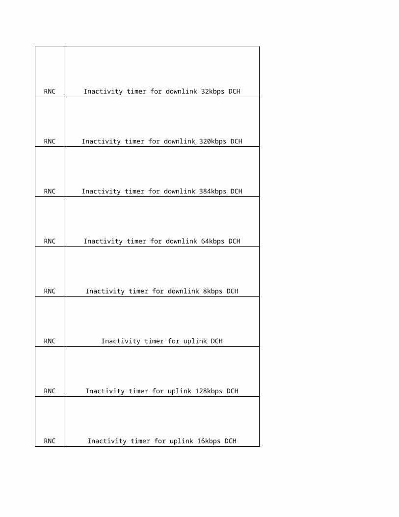
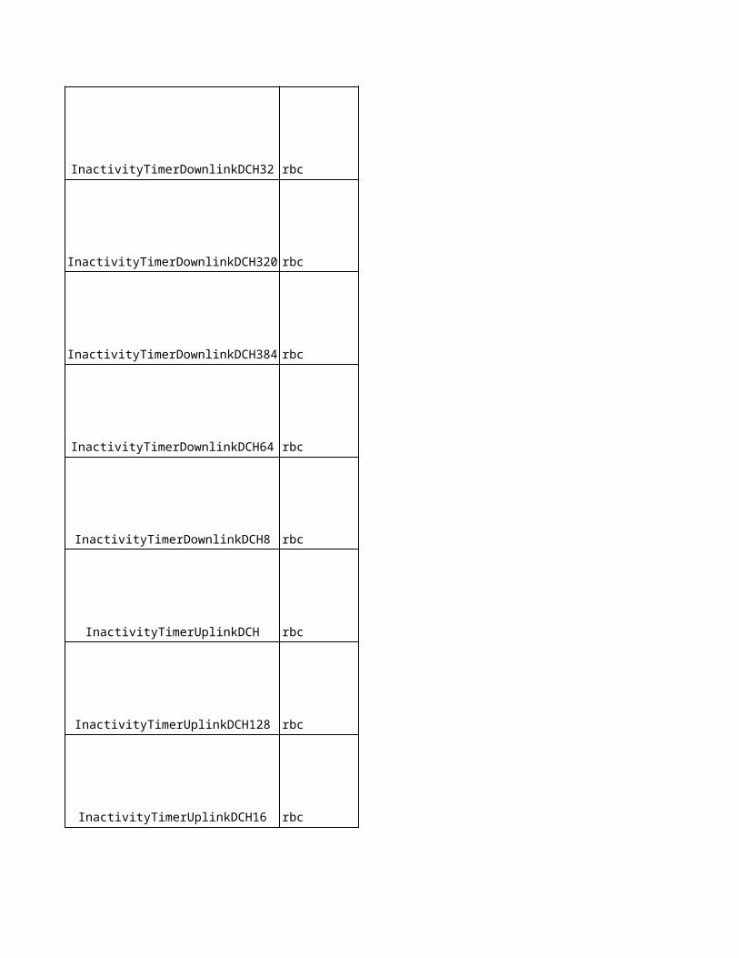
RNC Inactivity timer for downlink 32kbps DCH InactivityTimerDownlinkDCH32
RNC Inactivity timer for downlink 320kbps DCH InactivityTimerDownlinkDCH320
RNC Inactivity timer for downlink 384kbps DCH InactivityTimerDownlinkDCH384
RNC Inactivity timer for downlink 64kbps DCH InactivityTimerDownlinkDCH64
RNC Inactivity timer for downlink 8kbps DCH InactivityTimerDownlinkDCH8
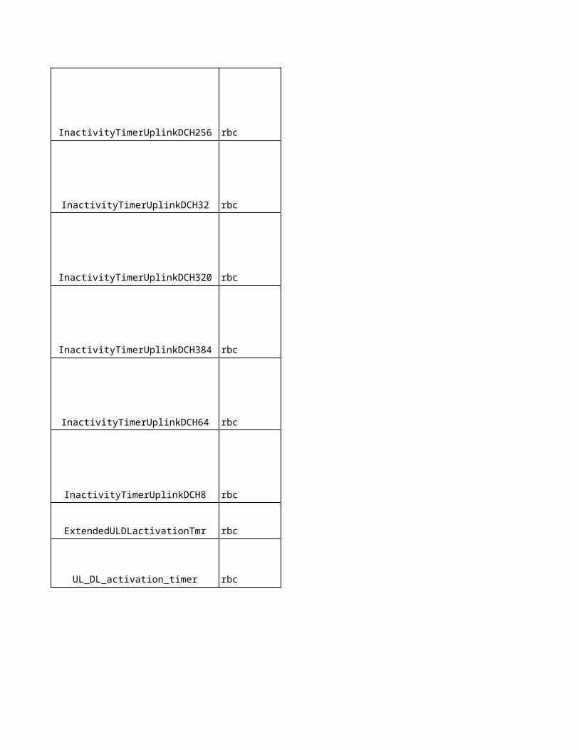
RNC Inactivity timer for uplink DCH InactivityTimerUplinkDCH
RNC Inactivity timer for uplink 128kbps DCH InactivityTimerUplinkDCH128
RNC Inactivity timer for uplink 16kbps DCH InactivityTimerUplinkDCH16
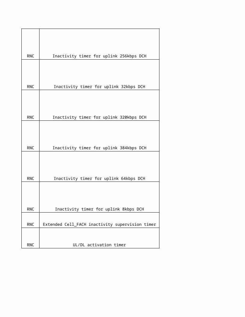
RNC Inactivity timer for uplink 256kbps DCH InactivityTimerUplinkDCH256
RNC Inactivity timer for uplink 32kbps DCH InactivityTimerUplinkDCH32
RNC Inactivity timer for uplink 320kbps DCH InactivityTimerUplinkDCH320
RNC Inactivity timer for uplink 384kbps DCH InactivityTimerUplinkDCH384
RNC Inactivity timer for uplink 64kbps DCH InactivityTimerUplinkDCH64
RNC Inactivity timer for uplink 8kbps DCH InactivityTimerUplinkDCH8
RNC Extended Cell_FACH inactivity supervision timer ExtendedULDLactivationTmr
RNC UL/DL activation timer UL_DL_activation_timer
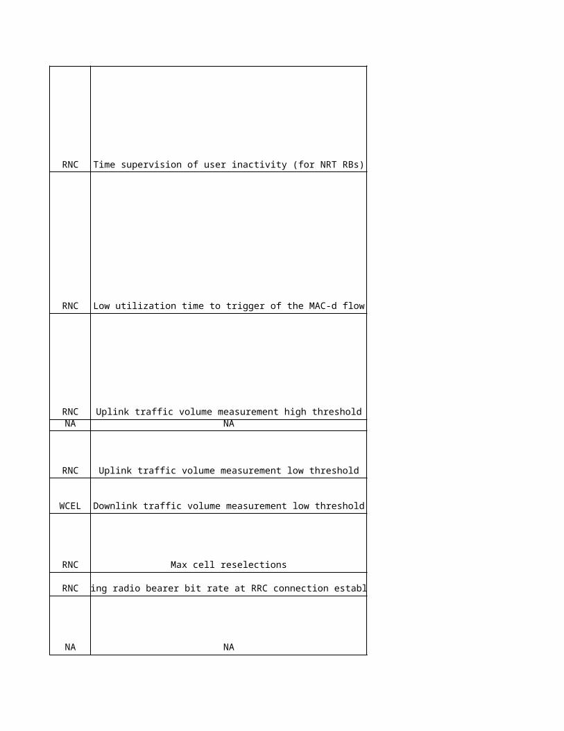
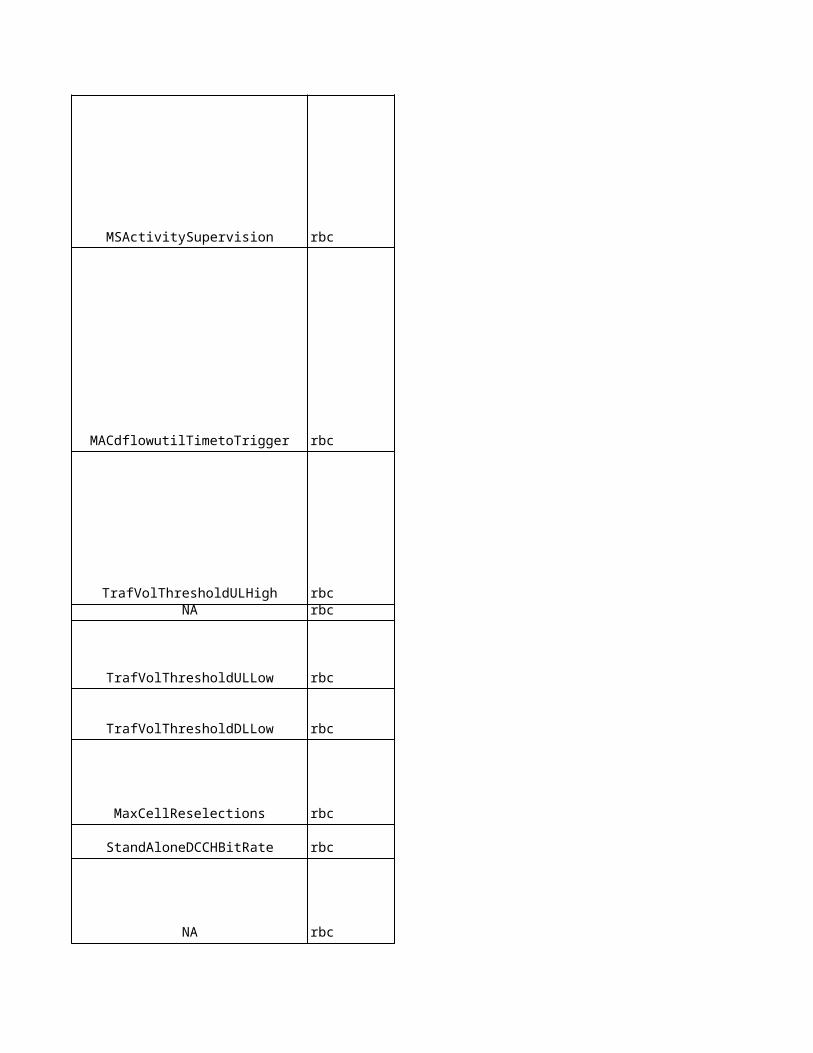
RNC Time supervision of user inactivity (for NRT RBs) MSActivitySupervision
RNC Low utilization time to trigger of the MAC-d flow MACdflowutilTimetoTrigger
RNC Uplink traffic volume measurement high threshold TrafVolThresholdULHighNA NA NA
RNC Uplink traffic volume measurement low threshold TrafVolThresholdULLow
WCEL Downlink traffic volume measurement low threshold TrafVolThresholdDLLow
RNC Max cell reselections MaxCellReselections
RNC Signalling radio bearer bit rate at RRC connection establishment StandAloneDCCHBitRate
NA NA NA
NA NA NA
NA NA NA
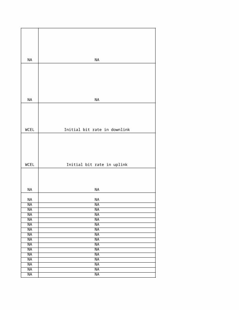
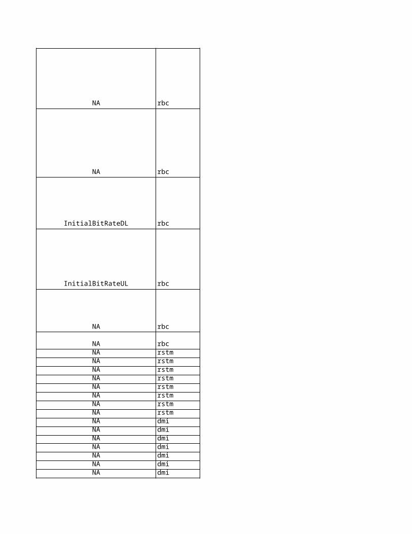
WCEL Initial bit rate in downlink InitialBitRateDL
WCEL Initial bit rate in uplink InitialBitRateUL
NA NA NA
NA NA NANA NA NANA NA NANA NA NANA NA NANA NA NANA NA NANA NA NANA NA NANA NA NANA NA NANA NA NANA NA NANA NA NANA NA NANA NA NANA NA NANA NA NANA NA NANA NA NANA NA NANA NA NANA NA NA
NA NA NANA NA NA
NA NA NA
NA NA NA
Sie
me
ns
Ob
jec
t
Sie
me
ns
Lo
ng
Na
me
Sie
me
ns
na
me
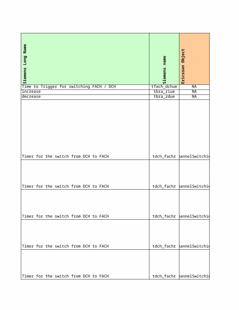
rbc Time to Trigger for switching FACH / DCH tfach_dchuerbc tbra_riuerbc tbra_rdue
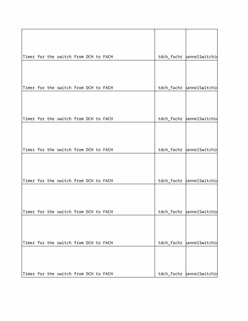
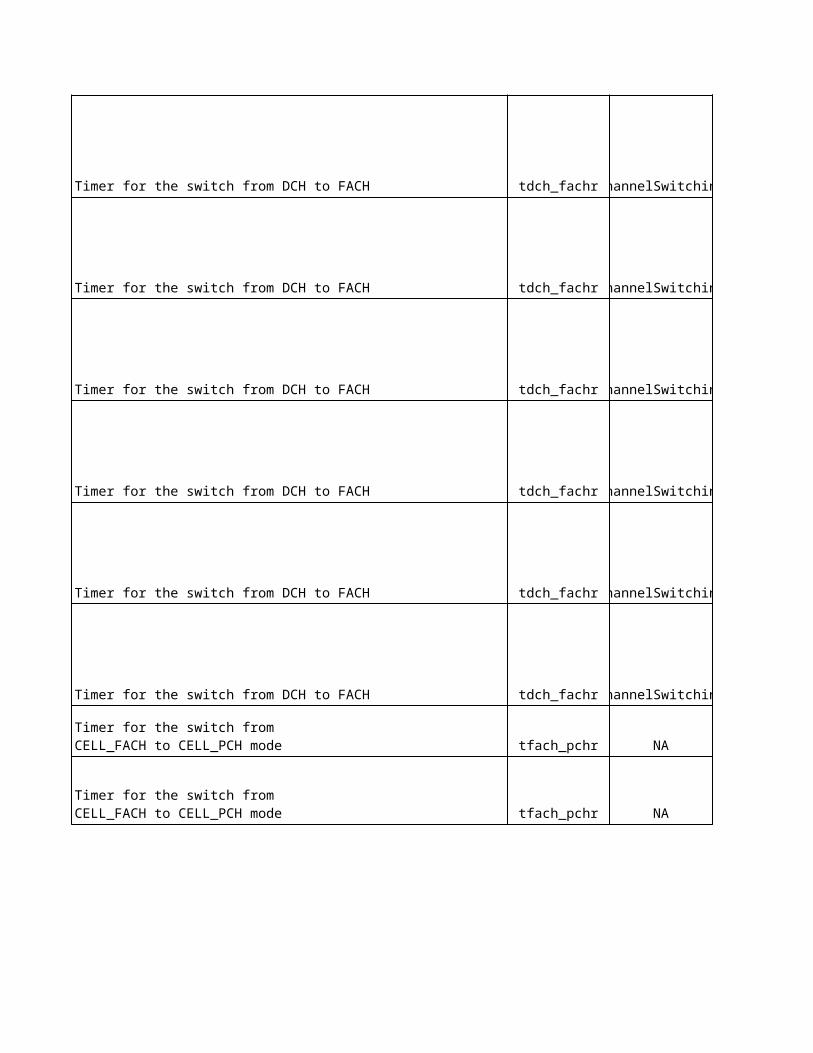
rbc Timer for the switch from DCH to FACH tdch_fachr
rbc Timer for the switch from DCH to FACH tdch_fachr
rbc Timer for the switch from DCH to FACH tdch_fachr
rbc Timer for the switch from DCH to FACH tdch_fachr
rbc Timer for the switch from DCH to FACH tdch_fachr
increasedecrease
rbc Timer for the switch from DCH to FACH tdch_fachr
rbc Timer for the switch from DCH to FACH tdch_fachr
rbc Timer for the switch from DCH to FACH tdch_fachr
rbc Timer for the switch from DCH to FACH tdch_fachr
rbc Timer for the switch from DCH to FACH tdch_fachr
rbc Timer for the switch from DCH to FACH tdch_fachr
rbc Timer for the switch from DCH to FACH tdch_fachr
rbc Timer for the switch from DCH to FACH tdch_fachr
rbc Timer for the switch from DCH to FACH tdch_fachr
rbc Timer for the switch from DCH to FACH tdch_fachr
rbc Timer for the switch from DCH to FACH tdch_fachr
rbc Timer for the switch from DCH to FACH tdch_fachr
rbc Timer for the switch from DCH to FACH tdch_fachr
rbc Timer for the switch from DCH to FACH tdch_fachr
rbc tfach_pchr
rbc tfach_pchr
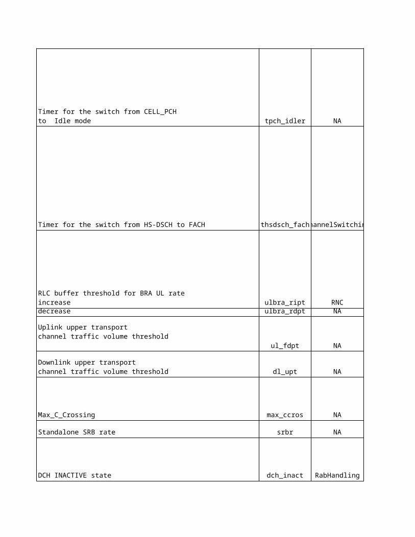
rbc tpch_idler
Timer for the switch from CELL_FACH to CELL_PCH mode
Timer for the switch from CELL_FACH to CELL_PCH mode
Timer for the switch from CELL_PCH to Idle mode
rbc Timer for the switch from HS-DSCH to FACH thsdsch_fach
rbc ulbra_riptrbc ulbra_rdpt
rbc ul_fdpt
rbc dl_upt
rbc Max_C_Crossing max_ccros
rbc Standalone SRB rate srbr
rbc DCH INACTIVE state dch_inact
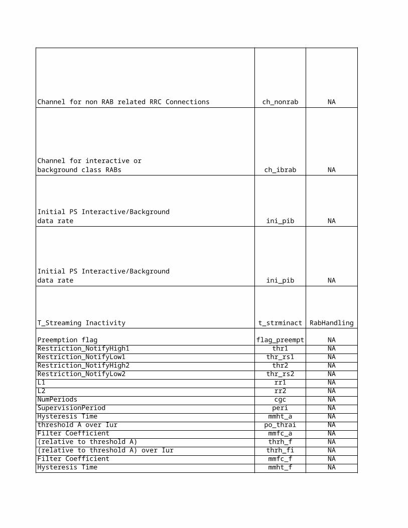
rbc Channel for non RAB related RRC Connections ch_nonrab
RLC buffer threshold for BRA UL rate increasedecrease
Uplink upper transport channel traffic volume threshold
Downlink upper transport channel traffic volume threshold
rbc ch_ibrab
rbc ini_pib
rbc ini_pib
rbc T_Streaming Inactivity t_strminact
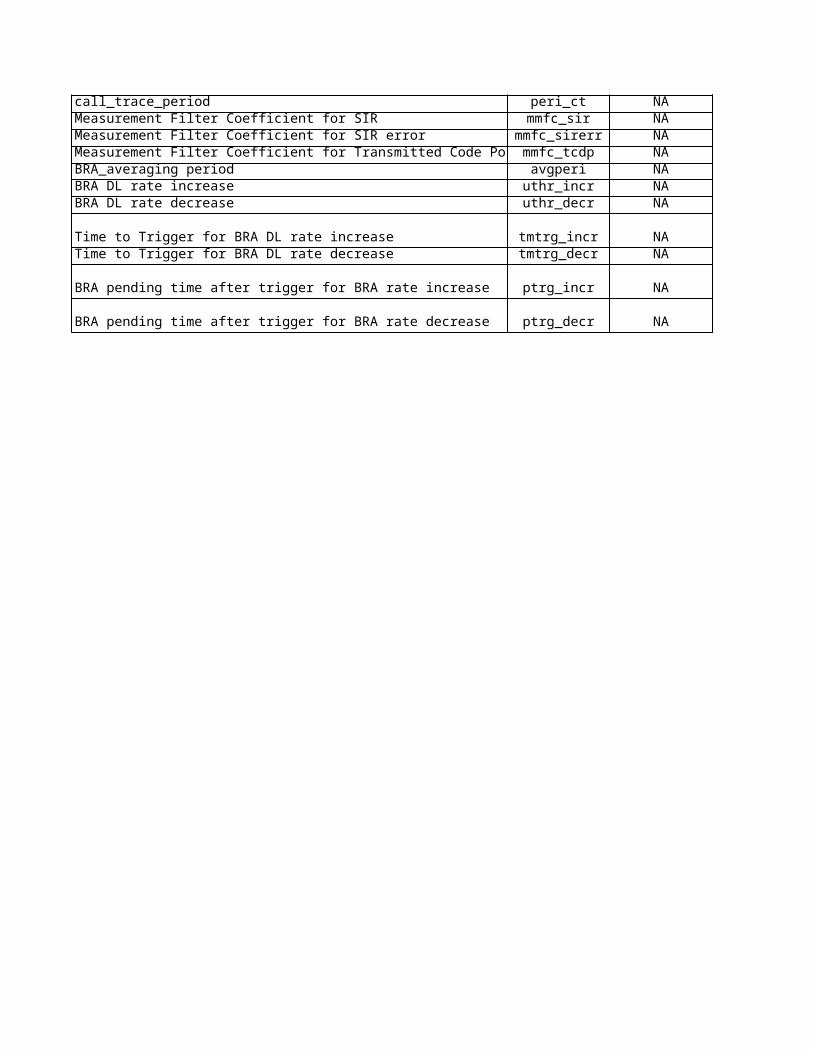
rbc Preemption flag flag_preemptrstm Restriction_NotifyHigh1 thr1rstm Restriction_NotifyLow1 thr_rs1rstm Restriction_NotifyHigh2 thr2rstm Restriction_NotifyLow2 thr_rs2rstm L1 rr1rstm L2 rr2rstm NumPeriods cgcrstm SupervisionPeriod peridmi mmht_admi po_thraidmi mmfc_admi thrh_fdmi thrh_fidmi mmfc_fdmi mmht_fdmi call_trace_period peri_ctdmi Measurement Filter Coefficient for SIR mmfc_sirdmi Measurement Filter Coefficient for SIR error mmfc_sirerrdmi Measurement Filter Coefficient for Transmitted Code Power mmfc_tcdpbumi BRA_averaging period avgperibumi uthr_incrbumi uthr_decr
bumi Time to Trigger for BRA DL rate increase tmtrg_incrbumi Time to Trigger for BRA DL rate decrease tmtrg_decr
Channel for interactive or background class RABs
Initial PS Interactive/Background data rate
Initial PS Interactive/Background data rate
Hysteresis Timethreshold A over IurFilter Coefficient(relative to threshold A)(relative to threshold A) over IurFilter CoefficientHysteresis Time
BRA DL rate increaseBRA DL rate decrease
bumi BRA pending time after trigger for BRA rate increase ptrg_incr
bumi BRA pending time after trigger for BRA rate decrease ptrg_decr
Eri
cs
so
n O
bje
ct
Eri
cs
so
n L
on
g N
am
e
Eri
cs
so
n n
am
e
No
kia
pro
po
se
d
Sie
me
ns
cu
rre
nt
Eri
cs
so
n c
urr
en
t
Ag
ree
d
No
kia
Un
it
Sie
me
ns
Un
it
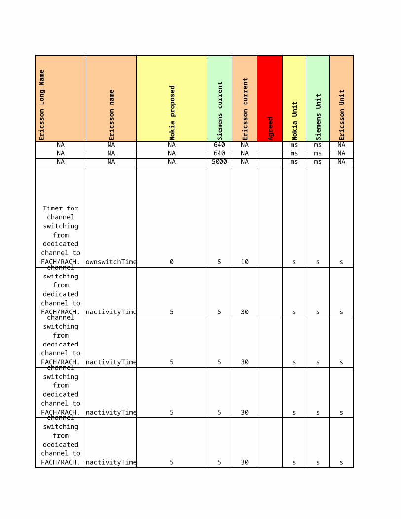
NA NA NA NA 640 NA ms msNA NA NA NA 640 NA ms msNA NA NA NA 5000 NA ms ms
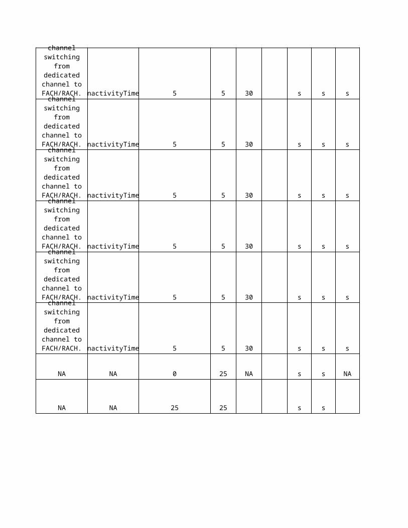
ChannelSwitching downswitchTimer 0 5 10 s s
ChannelSwitching inactivityTimer 5 5 30 s s
ChannelSwitching inactivityTimer 5 5 30 s s
ChannelSwitching inactivityTimer 5 5 30 s s
ChannelSwitching inactivityTimer 5 5 30 s s
Timer for channel
switching from dedicated channel to
FACH/RACH.
Timer for channel
switching from dedicated channel to
FACH/RACH.
Timer for channel
switching from dedicated channel to
FACH/RACH.
Timer for channel
switching from dedicated channel to
FACH/RACH.
Timer for channel
switching from dedicated channel to
FACH/RACH.
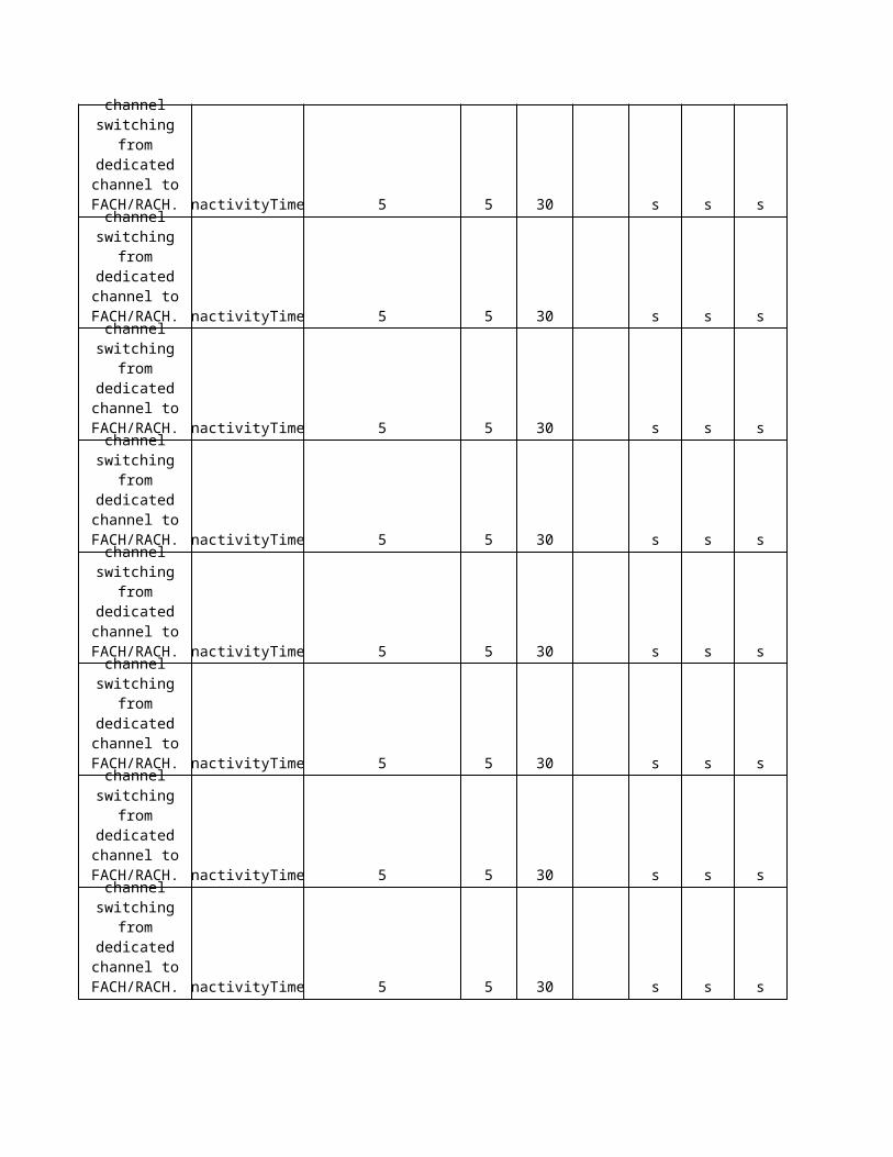
ChannelSwitching inactivityTimer 5 5 30 s s
ChannelSwitching inactivityTimer 5 5 30 s s
ChannelSwitching inactivityTimer 5 5 30 s s
ChannelSwitching inactivityTimer 5 5 30 s s
ChannelSwitching inactivityTimer 5 5 30 s s
ChannelSwitching inactivityTimer 5 5 30 s s
ChannelSwitching inactivityTimer 5 5 30 s s
ChannelSwitching inactivityTimer 5 5 30 s s
ChannelSwitching inactivityTimer 5 5 30 s s
Timer for channel
switching from dedicated channel to
FACH/RACH.
Timer for channel
switching from dedicated channel to
FACH/RACH.
Timer for channel
switching from dedicated channel to
FACH/RACH.
Timer for channel
switching from dedicated channel to
FACH/RACH.
Timer for channel
switching from dedicated channel to
FACH/RACH.
Timer for channel
switching from dedicated channel to
FACH/RACH.
Timer for channel
switching from dedicated channel to
FACH/RACH.
Timer for channel
switching from dedicated channel to
FACH/RACH.
Timer for channel
switching from dedicated channel to
FACH/RACH.
ChannelSwitching inactivityTimer 5 5 30 s s
ChannelSwitching inactivityTimer 5 5 30 s s
ChannelSwitching inactivityTimer 5 5 30 s s
ChannelSwitching inactivityTimer 5 5 30 s s
ChannelSwitching inactivityTimer 5 5 30 s s
NA NA NA 0 25 NA s s
NA NA NA 25 25 s s
NA NA NA 0 1 m s
Timer for channel
switching from dedicated channel to
FACH/RACH.
Timer for channel
switching from dedicated channel to
FACH/RACH.
Timer for channel
switching from dedicated channel to
FACH/RACH.
Timer for channel
switching from dedicated channel to
FACH/RACH.
Timer for channel
switching from dedicated channel to
FACH/RACH.
ChannelSwitching 0 30 10 s s
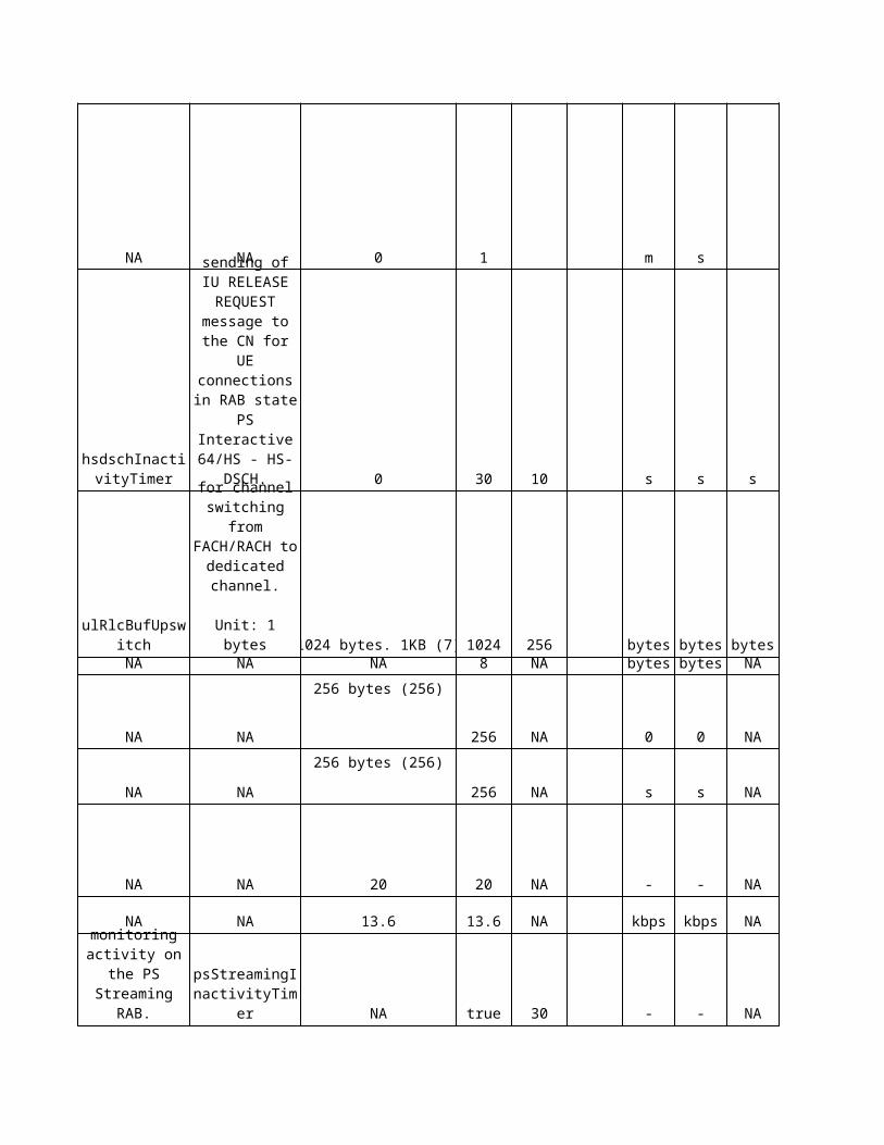
RNC 1024 bytes. 1KB (7) 1024 256 bytes bytesNA NA NA NA 8 NA bytes bytes
NA NA NA
256 bytes (256)
256 NA 0 0
NA NA NA
256 bytes (256)
256 NA s s
NA NA NA 20 20 NA - -
NA NA NA 13.6 13.6 NA kbps kbps
RabHandling NA true 30 - -
NA NA NA NA dedc NA - -
hsdschInactivityTimer
Timer for sending of IU
RELEASE REQUEST message to
the CN for UE connections in RAB state PS
Interactive 64/HS - HS-
DSCH.
ulRlcBufUpswitch
Uplink threshold for
channel switching from FACH/RACH to dedicated
channel.
Unit: 1 bytes
Timer for monitoring
activity on the PS Streaming
RAB.psStreamingInactivityTimer
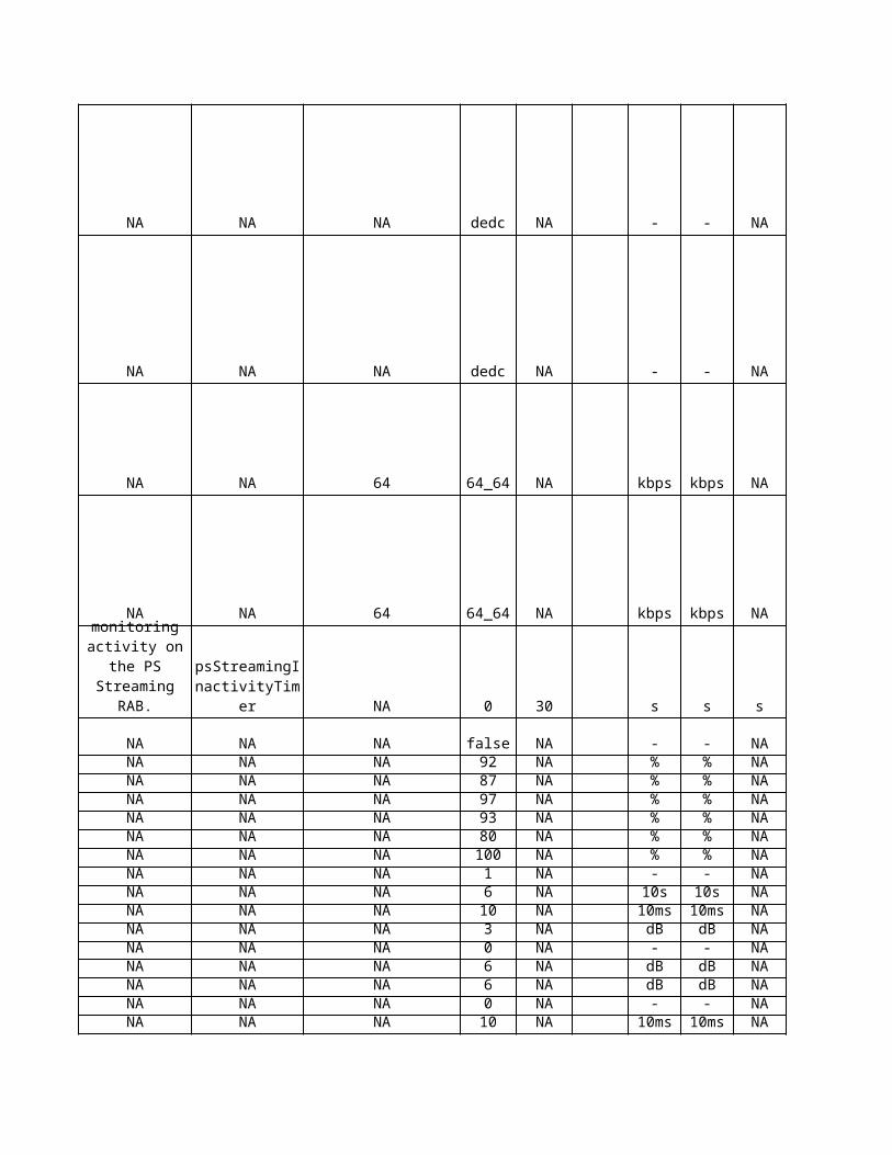
NA NA NA NA dedc NA - -
NA NA NA 64 64_64 NA kbps kbps
NA NA NA 64 64_64 NA kbps kbps
RabHandling NA 0 30 s s
NA NA NA NA false NA - -NA NA NA NA 92 NA % %NA NA NA NA 87 NA % %NA NA NA NA 97 NA % %NA NA NA NA 93 NA % %NA NA NA NA 80 NA % %NA NA NA NA 100 NA % %NA NA NA NA 1 NA - -NA NA NA NA 6 NA 10s 10sNA NA NA NA 10 NA 10ms 10msNA NA NA NA 3 NA dB dBNA NA NA NA 0 NA - -NA NA NA NA 6 NA dB dBNA NA NA NA 6 NA dB dBNA NA NA NA 0 NA - -NA NA NA NA 10 NA 10ms 10msNA NA NA NA 1 NA sec secNA NA NA NA 0 NA - -NA NA NA NA 0 NA - -NA NA NA NA 0 NA - -NA NA NA NA 500 NA ms msNA NA NA NA 80 NA % %NA NA NA NA 10 NA % %
NA NA NA NA 1 NA - -NA NA NA NA 15 NA - -
Timer for monitoring
activity on the PS Streaming
RAB.psStreamingInactivityTimer
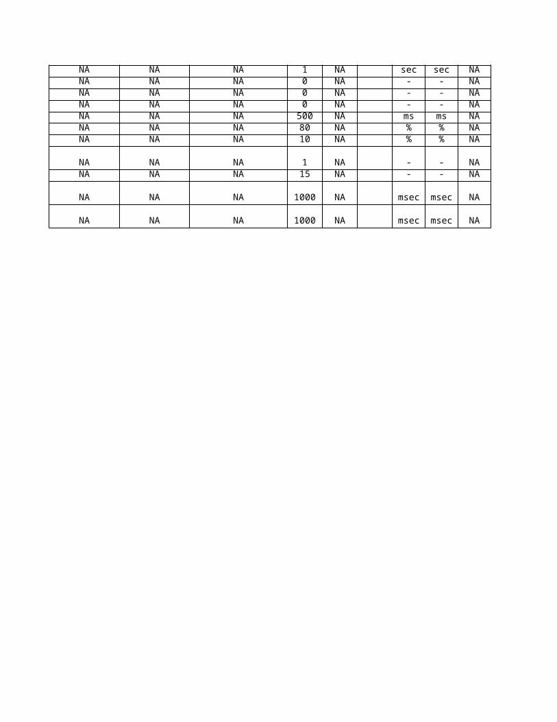
NA NA NA NA 1000 NA msec msec
NA NA NA NA 1000 NA msec msec
Eri
cs
so
n U
nit
NANANA
s
s
s
s
s
s
s
s
s
s
s
s
s
s
s
s
s
s
s
NA
s
bytesNA
NA
NA
NA
NA
NA
NA
NA
NA
NA
s
NANANANANANANANANANANANANANANANANANANANANANANA
NANA
NA
NA
No
kia
De
sc
rip
tio
n
NANANA
When any other value than zero is set to the CellDCHtestTmr, this value is used instead of the RB/DCH specific inactivity timers InactivityTimerUplinkDCH and InactivityTimerDownlinkDCH. The timer CellDCHtestTmr defines the maximum time an inactive MS is allowed to remain in the CELL_DCH state. In the expiry of the timer, the MS is switched to the CELL_FACH state if the parameter ToCellFACHinTest is equal to 'Yes' and the procedures in the CELL_FACH state continue as normal. If ToCellFACHinTest is equal to 'No', an Iu release procedure is initiated and the MS is switched to the idle mode. Note! This parameter is only used for testing purposes and it does not affect any other state transfer recovery function.
The time indicating how long the radio and transmission resources are reserved after silence detection on downlink DCH before release procedures. Default values: 8 kbps: 5 s 16 kbps: 5 s 32 kbps: 5 s 64 kbps: 3 s 128 kbps: 2 s 256 kbps: 2 s 320 kbps: 2 s 384 kbps: 2 s
The time indicating how long the radio and transmission resources are reserved after silence detection on downlink DCH before release procedures. Timer is defined separately for each bit rate. Parameter value 255 (infinity) means that NRT DCH inactivity supervision is not used.
The time indicating how long the radio and transmission resources are reserved after silence detection on downlink DCH before release procedures. Timer is defined separately for each bit rate. Parameter value 255 (infinity) means that NRT DCH inactivity supervision is not used.
The time indicating how long the radio and transmission resources are reserved after silence detection on downlink DCH before release procedures. Timer is defined separately for each bit rate. Parameter value 255 (infinity) means that NRT DCH inactivity supervision is not used.
The time indicating how long the radio and transmission resources are reserved after silence detection on downlink DCH before release procedures. Timer is defined separately for each bit rate. Parameter value 255 (infinity) means that NRT DCH inactivity supervision is not used.
The time indicating how long the radio and transmission resources are reserved after silence detection on downlink DCH before release procedures. Timer is defined separately for each bit rate. Parameter value 255 (infinity) means that NRT DCH inactivity supervision is not used.
The time indicating how long the radio and transmission resources are reserved after silence detection on downlink DCH before release procedures. Timer is defined separately for each bit rate. Parameter value 255 (infinity) means that NRT DCH inactivity supervision is not used.
The time indicating how long the radio and transmission resources are reserved after silence detection on downlink DCH before release procedures. Timer is defined separately for each bit rate. Parameter value 255 (infinity) means that NRT DCH inactivity supervision is not used.
The time indicating how long the radio and transmission resources are reserved after silence detection on downlink DCH before release procedures. Timer is defined separately for each bit rate. Parameter value 255 (infinity) means that NRT DCH inactivity supervision is not used.
The time indicating how long the radio and transmission resources are reserved after silence detection on uplink DCH before release procedures. Default values: 8 kbps: 5 s 16 kbps: 5 s 32 kbps: 5 s 64 kbps: 3 s 128 kbps: 2 s 256 kbps: 2 s 320 kbps: 2 s 384 kbps: 2 s
The time indicating how long the radio and transmission resources are reserved after silence detection on uplink DCH before release procedures. Timer is defined separately for each bit rate. Parameter value 255 (infinity) means that NRT DCH inactivity supervision is not used.
The time indicating how long the radio and transmission resources are reserved after silence detection on uplink DCH before release procedures. Timer is defined separately for each bit rate. Parameter value 255 (infinity) means that NRT DCH inactivity supervision is not used.
The time indicating how long the radio and transmission resources are reserved after silence detection on uplink DCH before release procedures. Timer is defined separately for each bit rate. Parameter value 255 (infinity) means that NRT DCH inactivity supervision is not used.
The time indicating how long the radio and transmission resources are reserved after silence detection on uplink DCH before release procedures. Timer is defined separately for each bit rate. Parameter value 255 (infinity) means that NRT DCH inactivity supervision is not used.
The time indicating how long the radio and transmission resources are reserved after silence detection on uplink DCH before release procedures. Timer is defined separately for each bit rate. Parameter value 255 (infinity) means that NRT DCH inactivity supervision is not used.
The time indicating how long the radio and transmission resources are reserved after silence detection on uplink DCH before release procedures. Timer is defined separately for each bit rate. Parameter value 255 (infinity) means that NRT DCH inactivity supervision is not used.
The time indicating how long the radio and transmission resources are reserved after silence detection on uplink DCH before release procedures. Timer is defined separately for each bit rate. Parameter value 255 (infinity) means that NRT DCH inactivity supervision is not used.
The time indicating how long the radio and transmission resources are reserved after silence detection on uplink DCH before release procedures. Timer is defined separately for each bit rate. Parameter value 255 (infinity) means that NRT DCH inactivity supervision is not used.
This parameter defines an extended Cell_FACH state inactivity supervision time used by the RNC instead of the normal UL_DL_Activation_Timer. If set to a value greater than zero, this value is used for all UEs not supporting the Cell/URA_PCH state.
This timer is used on MAC -c to detect idle periods on data transmission (NRT RBs and SRBs) for the UE, which is in Cell_FACH state. Based on this timer the MAC -c shall give the No_Data indication to the RRC, which further can change the state of the RRC from Cell_FACH state to the Cell_PCH state (or URA_PCH state).
The MSActivitySupervision timer is used in the RRC states CELL_PCH and URA_PCH for supervising the inactivity of NRT RAB(s). The timer starts when a state transition to either state is executed. The MSActivitySupervision timer stops when any activity of NRT RAB(s) is detected and the MS is moved to the CELL_FACH or CELL_DCH state. The timer restarts (from the initial value) when the inactivity of the NRT RAB(s) is detected and the MS is moved back to the CELL_PCH or URA_PCH state again. In the expiry of the MSActivitySupervision timer, when the first “inactive state indication” (i.e. cell/URA update, which does not cause the (re)initiation of the signalling or data flow) is received from the MS, the RNC asks SGSN to release the Iu connection. Note! If the parameter value is set to zero, the state transition to CELL_PCH/URA_PCH is not allowed. When inactivity is detected in the CELL_FACH state, the MS is switched to the idle mode.
This parameter defines the low utilisation time to trigger the timer of the throughput measurement of the MAC-d flow.
NA
NA
NA
The parameter defines the threshold of data in RLC buffer of RB in bytes. This threshold triggers the uplink traffic volume measurement report when the UE is in a Cell_DCH state and bit rate higher than 16 kbps is allocated for the radio bearer. The parameter is sent to the UE using the RRC: MEASUREMENT CONTROL message. Note: If flexible upgrade of NRT DCH data rate is activated by the FlexUpgrUsage parameter, the threshold of data in RLC buffer of RB in bytes is defined by the TrafVolThresholdULHighBitRate parameter instead of this parameter if the allocated DCH bit rate is below the maximum bit rate of the radio bearer. The high threshold of the 16 and 8 kbps DCH is fixed: - 512 bytes for the RB whose NRT DCH bit rate is 8 kbps. - 512 bytes for the RB whose NRT DCH bit rate is 16 kbps.
This parameter defines, in bytes, the threshold of data in the RLC buffers of SRB0, SRB1, SRB2, SRB3, SRB4 and all NRT RBs that triggers the uplink traffic volume measurement report, when the UE is in Cell_FACH state. Otherwise, UE sends data on RACH. This parameter is sent to the UE using an RRC: MEASUREMENT CONTROL message.
This parameter defines, in bytes, the threshold of data in the RLC buffers of SRB3, SRB4 and all NRT RBs that triggers the downlink traffic volume measurement report (capacity request) on MAC, when UE is in Cell_FACH state. Otherwise, RNC sends data on FACH.
Maximum allowed number of Cell Reselections in CELL_FACH or CELL_PCH state before transition to URA_PCH state. Amount of cell reselection is counted in both CELL_FACH and CELL_PCH states. When the MS is in CELL_FACH state, the value of counter MaxCellReselections cannot be used as a trigger for CELL_FACH to URA_PCH transition, but it is used when deciding a target state after the MAC-c entity has sent an inactivity indication to Layer 3.
Parameter defines the bit rate to be used for the signalling radio bearer at the RRC connection establishment. This bit rate is used for RRC signalling until a RAB has been established for the RRC connection.
NA
NA
NANANANANANANANANANANANANANANANANANANANANANANA
NANA
The parameter defines the initial bit rate in the downlink that can be allocated by the PS in the schedule situation. The PS does not schedule downlink NRT DCH bit rates that are below the value of this parameter. The allocated bit rate corresponds to the highest bit rate in the TFS from which the TFCS is constructed. Note: If the maximum bit rate of the RAB is below the value of the minimum allowed bit rate (MinAllowedBitRate) or initial bit rate, it is allowed to schedule a lower NRT DCH bit rate. The maximum bit rate of the RAB is used as a new minimum allowed bit rate or initial bit rate for the RRC connection in question.
The parameter defines the initial bit rate in the uplink that can be allocated by the PS in schedule situation. PS does not schedule uplink NRT DCH bit rates below the value of this parameter. The allocated bit rate corresponds to the highest bit rate in the TFS from which the TFCS is constructed.
Note: If the maximum bit rate of the RAB is below the value of minimum allowed bit rate (MinAllowedBitRateUL) or initial bit rate, it is allowed to schedule a lower NRT DCH bit rate. The maximum bit rate of the RAB is used as a new minimum or initial bit rate for the RRC connection in question.
NA
NA
Sie
me
ns
De
sc
rip
tio
n
Time to Trigger for switching FACH/DCHTime to Trigger for BRA UL rate increaseTime to Trigger for BRA UL rate decrease Used for UE event 4B (on DCH)
Period of uplink and downlink inactivity before the PS I/B RAB is switched to FACH
Period of uplink and downlink inactivity before the PS I/B RAB is switched to FACH
Period of uplink and downlink inactivity before the PS I/B RAB is switched to FACH
Period of uplink and downlink inactivity before the PS I/B RAB is switched to FACH
Period of uplink and downlink inactivity before the PS I/B RAB is switched to FACH
Period of uplink and downlink inactivity before the PS I/B RAB is switched to FACH
Period of uplink and downlink inactivity before the PS I/B RAB is switched to FACH
Period of uplink and downlink inactivity before the PS I/B RAB is switched to FACH
Period of uplink and downlink inactivity before the PS I/B RAB is switched to FACH
Period of uplink and downlink inactivity before the PS I/B RAB is switched to FACH
Period of uplink and downlink inactivity before the PS I/B RAB is switched to FACH
Period of uplink and downlink inactivity before the PS I/B RAB is switched to FACH
Period of uplink and downlink inactivity before the PS I/B RAB is switched to FACH
Period of uplink and downlink inactivity before the PS I/B RAB is switched to FACH
Period of uplink and downlink inactivity before the PS I/B RAB is switched to FACH
Period of uplink and downlink inactivity before the PS I/B RAB is switched to FACH
Period of uplink and downlink inactivity before the PS I/B RAB is switched to FACH
Period of uplink and downlink inactivity before the PS I/B RAB is switched to FACH
Period of uplink and downlink inactivity before the PS I/B RAB is switched to FACH
Timer for the switch from CELL_FACH to CELL_PCH mode
Timer for the switch from CELL_FACH to CELL_PCH mode
Timer for the switch from CELL_PCH to Idle mode
RLC buffer threshold for BRA UL rate increase This value must be greater or equal ulbra_rdptRLC buffer threshold for BRA UL rate decrease This value must be smaller or equal ulbra_ript
Uplink upper transport channel traffic volume threshold
Downlink upper transport channel traffic volume threshold
Maximum number of cell crossing in CELL_PCH mode before switch to URA_PCH mode
Rate of standalone DCCH.
Period of uplink and downlink inactivity before the PS I/B RAB is switched from HS-DSCH to FACH. 0 means that inactivity is not monitored and the connection is not switched to FACH
Allowed: Inactive Interactive/background PS RABs on multicall are reconfigured to UL:0 DL: 0 kbps.Not allowed: Inactive PS RABs on multicall are not reconfigured.
Indicates channel type for RRC Connection establishment when establishment cause is:- Registration, - Detach,- Originating High Priority Signalling,- Originating Low Priority Signalling,- Terminating High Priority Signalling,- Terminating Low Priority Signalling
Initial bit rate to be assigned at PS I/B RAB setup
Initial bit rate to be assigned at PS I/B RAB setup
Timer to release inactive PS Streaming RABs The value 0 means no release due to inactivity
Restriction threshold value of restriction level 1Restore threshold value of restriction level 1Restriction threshold value of restriction level 2Restore threshold value of restriction level 2Restriction control rate of restriction level 1Restriction control rate of restriction level 2Number of connect eventsMeasurement periodNode B BB card limitation (N*100ms) rounding to the nearest 100ms is performed on Node BThis parameter is used to define threshold A on cells belonging to the DRNC.Filter coefficient for layer 3 filtering.Power offset relative to power threshold A Event F threshold = Event A threshold – Power offset for threshold FThis parameter is used to define threshold F on cells belonging to the DRNC.Filter coefficient for layer 3 filtering.Node B BB card limitation (N*100ms) rounding to the nearest 100ms is performed on Node BDetermines the period for the dedicated measurement for Call TraceFilter coefficient for call trace measurements for SIRFilter coefficient for call trace measurements for SIR errorFilter coefficient for call trace measurements for Transmitted Code PowerDownlink averaging periodUtilisation Threshold for BRA DL rate increaseUtilisation Threshold for BRA DL rate decrease
Time to Trigger for BRA DL rate decrease.
Indicates channel type for RRC Connection establishment when establishment cause is:- Originating Interactive Call,- Originating Background Call,- Terminating Interactive Call,- Terminating Background Call,Indicates channel type for RAB establishment when traffic class is:- Interactive- Background
RNC parameter. Suggestion: Same value should be used across the whole network.The parameter is used to switch the feature ON (“True”) and OFF (“False”).
Time to Trigger for BRA DL rate increase.Recommendation: Replace Default by optimized value
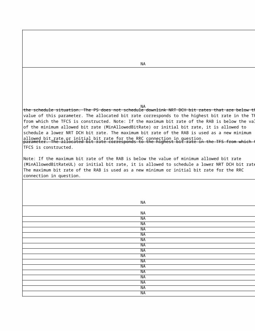
Period between successive rate decrease triggersIndicates the period of time during which it is forbidden to buffer utilisation low report.
Period between successive rate decrease triggersIndicates the period of time during which it is forbidden to buffer utilisation low report.
Eri
cs
so
n D
es
cri
pti
on
NANANA
downswitchTimer : long, Default = 10, Range = 0..1000 Timer for channel
switching from dedicated channel to FACH/RACH.Unit: 100 msResolution: 5 (= 500 ms)
0 indicates that traffic-volume-initiated channel switching from dedicated channel to FACH/RACH is
disabled5: 500 ms = 0.5 s10: 1000 ms = 1 s
...1000: 100000 ms = 100 s
Time not including data transmission, after which UTRAN will send IU RELEASE REQUEST message
to the CN for UEs in state CELL_FACH.
Unit: 1 secondResolution: 1
Time not including data transmission, after which UTRAN will send IU RELEASE REQUEST message
to the CN for UEs in state CELL_FACH.
Unit: 1 secondResolution: 1
Time not including data transmission, after which UTRAN will send IU RELEASE REQUEST message
to the CN for UEs in state CELL_FACH.
Unit: 1 secondResolution: 1
Time not including data transmission, after which UTRAN will send IU RELEASE REQUEST message
to the CN for UEs in state CELL_FACH.
Unit: 1 secondResolution: 1
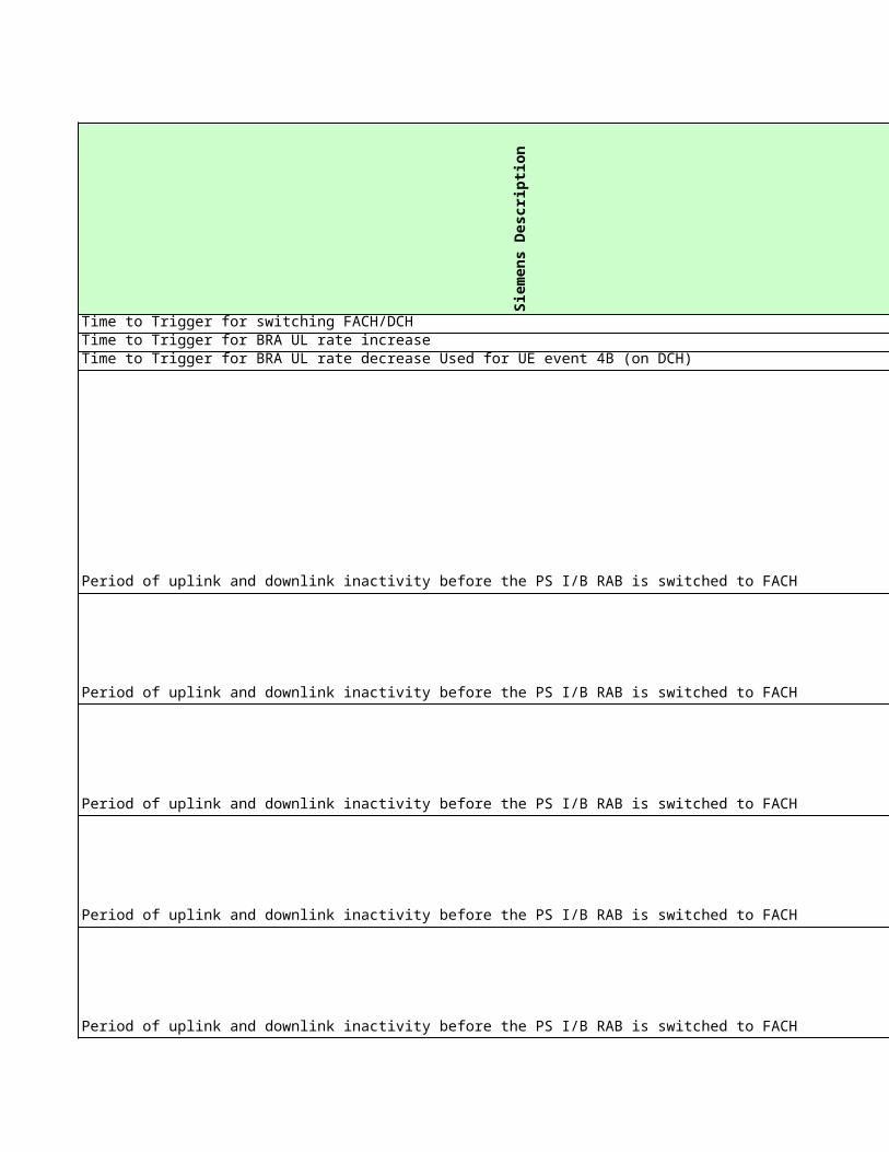
Time not including data transmission, after which UTRAN will send IU RELEASE REQUEST message
to the CN for UEs in state CELL_FACH.
Unit: 1 secondResolution: 1
Time not including data transmission, after which UTRAN will send IU RELEASE REQUEST message
to the CN for UEs in state CELL_FACH.
Unit: 1 secondResolution: 1
Time not including data transmission, after which UTRAN will send IU RELEASE REQUEST message
to the CN for UEs in state CELL_FACH.
Unit: 1 secondResolution: 1
Time not including data transmission, after which UTRAN will send IU RELEASE REQUEST message
to the CN for UEs in state CELL_FACH.
Unit: 1 secondResolution: 1
Time not including data transmission, after which UTRAN will send IU RELEASE REQUEST message
to the CN for UEs in state CELL_FACH.
Unit: 1 secondResolution: 1
Time not including data transmission, after which UTRAN will send IU RELEASE REQUEST message
to the CN for UEs in state CELL_FACH.
Unit: 1 secondResolution: 1
Time not including data transmission, after which UTRAN will send IU RELEASE REQUEST message
to the CN for UEs in state CELL_FACH.
Unit: 1 secondResolution: 1
Time not including data transmission, after which UTRAN will send IU RELEASE REQUEST message
to the CN for UEs in state CELL_FACH.
Unit: 1 secondResolution: 1
Time not including data transmission, after which UTRAN will send IU RELEASE REQUEST message
to the CN for UEs in state CELL_FACH.
Unit: 1 secondResolution: 1
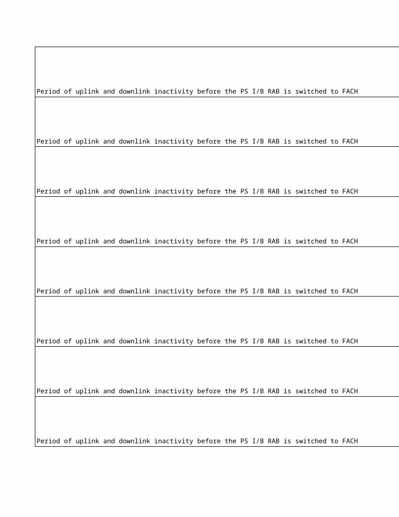
NA
NA
NA
Time not including data transmission, after which UTRAN will send IU RELEASE REQUEST message
to the CN for UEs in state CELL_FACH.
Unit: 1 secondResolution: 1
Time not including data transmission, after which UTRAN will send IU RELEASE REQUEST message
to the CN for UEs in state CELL_FACH.
Unit: 1 secondResolution: 1
Time not including data transmission, after which UTRAN will send IU RELEASE REQUEST message
to the CN for UEs in state CELL_FACH.
Unit: 1 secondResolution: 1
Time not including data transmission, after which UTRAN will send IU RELEASE REQUEST message
to the CN for UEs in state CELL_FACH.
Unit: 1 secondResolution: 1
Time not including data transmission, after which UTRAN will send IU RELEASE REQUEST message
to the CN for UEs in state CELL_FACH.
Unit: 1 secondResolution: 1
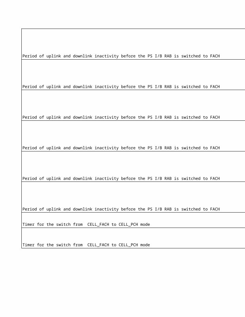
NA
NA
NA
NA
NA
NA
Timer for sending of IU RELEASE REQUEST message to the CN for UE connections in RAB state
PS Interactive 64/HS - HS-DSCH.
Unit: 1 s (seconds)Resolution: 1
The value 7200 seconds is used only for testing purposes.
Uplink threshold for channel switching from FACH/RACH to dedicated channel.
Unit: 1 bytes
Timer for monitoring activity on the PS Streaming RAB. When the timer expires, RNC will request the
CN to release the PS Streaming RAB.1=true0=False
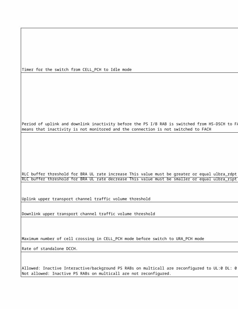
NA
NA
NA
NANANANANANANANANANANANANANANANANANANANANANANA
NANA
Timer for monitoring activity on the PS Streaming RAB. When the timer expires, RNC will request the
CN to release the PS Streaming RAB.1=true0=False
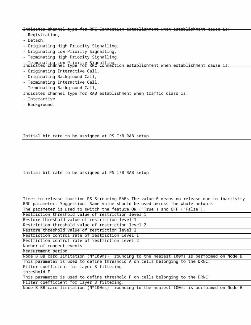
NA
NA
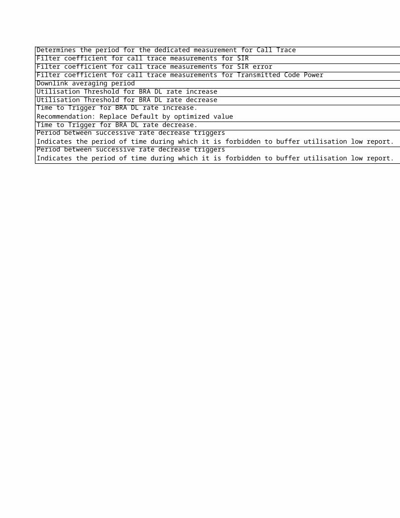
No
kia
Ob
jec
t
No
kia
Lo
ng
Na
me
No
kia
na
me
Sie
me
ns
Ob
jec
tWBTS DLTPCPatternPowerCount DLTPCPatternPowerCount sccsr
Outer Loop Power ControlNA NA NA olpc
RNC Step Size for DCH BLER calculation StepSizeForDCHBLER olpc
NA NA NA olpc
NA NA NA olpcNA NA NA dmi
Downlink Power Balancing
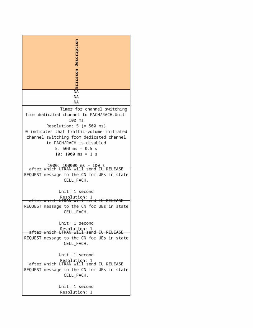
RNCTrigger for sending the updated reference power to BTSsMinPrefChange olpc
RNC Power Balancing on/off PowerBalancing dlpb
RNC Adjustment period time AdjustmentPeriod dlpb
RNC Adjustment ratio AdjustmentRatio dlpb
RNC Maximum adjustment step MaxAdjustmentStep dlpb
Sie
me
ns
Lo
ng
Na
me
Sie
me
ns
na
me
Eri
cs
so
n O
bje
ct
Eri
cs
so
n L
on
g N
am
e
Eri
cs
so
n n
am
e
DL TPC pattern 01 count dltpc01 NA NA NA
Threshold value for new update thr_upd NA NA NA
Step size step_size NA NA NA
SIRerror,min lowthr_sirerr PowerControlThe minimum allowed SIR target.sirMin
SIRerror,max upthr_sirerr PowerControlThe maximum allowed SIR target.sirMaxMeasurement Filter Coefficient for SIR error mmfc_sirerr NA NA NA
Update threshold thr_upd NA NA NA
PB System Upgrade Flag flag_pb PowerControl fixedRefPower
Adjustment Period, k adj_prd NA NA adjustmentPeriod
Adjustment Ratio, r adj_rto NA NA adjustmentRatio
Max Adjustment Step max_adj_stp NA NA maxAdjustmentStep
Fixed DL reference
power used in fixed
balancing DL PC method, expressed relative to
the PCPICH power.
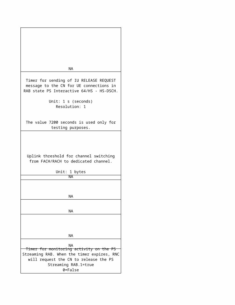
No
kia
pro
po
se
d
Sie
me
ns
cu
rre
nt
Eri
cs
so
n c
urr
en
t
Ag
ree
d
No
kia
Un
it
Sie
me
ns
Un
it
Eri
cs
so
n U
nit
3 8 NA - - NA
NA 0.1 NA dB dB NA
0.3 0.3 NA dB dB NA
NA -3 -82 dB dB dB
NA 3 100 dB dB dBNA 0 NA - - NA
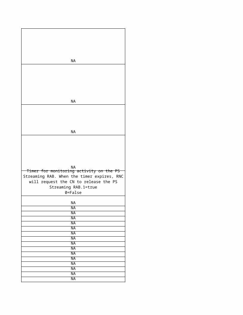
3 0.5 NA dB dB NA
Power Balancing is not in use (0) false 65 - - dB
2 frame
1 NA frames frames NA
0
50 NA dB dB NA
8 slot
2 NA slots slots NA
No
kia
De
sc
rip
tio
n
NA
NA
NANA
This parameter is used to calculate the value of IE DL TPC pattern 01 count, which is used when the uplink is out of synchronisation and the first radio link set towards the UE is set up. The computed IE is used to generate a sequence of TPC commands which progressively increase the UL DPCCH power by 0-24 dB over a four frame period. These sequences are repeated until synchronisation has been achieved. The parameter is set according to following table. Reading instructions: Param value n: resulting Power Increase if DTPC=1dB, resulting Power Increase if DPTC=2dB DTPC = Parameter UplinkInnerLoopPCStepSize Power Increase = Actual UL DPCCH power increase during a single four frame period. parameter value 1: 0 dB, 0 dB parameter value 2: 2 dB, 0 dB parameter value 3: 4 dB, 4 dB parameter value 4: 4 dB, 4 dB parameter value 5: 6 dB, 4 dB parameter value 6: 8 dB, 8 dB parameter value 7: 12 dB, 8 dB parameter value 8: 12 dB, 8 dB parameter value 9: 12 dB, 12 dB parameter value 10: 20 dB, 12 dB parameter value 11: 20 dB, 16 dB parameter value 12: 20 dB, 16 dB parameter value 13: 20 dB, 24 dB parameter value 14: 20 dB, 24 dB parameter value 15: 20 dB, 24 dB The parameter value is sent in configuration data (cell setup request) to the BTS. Note: BTS must be restarted for the modification to come into effect. Note: The uplink out of synchronization concept is specified in 3GPP TS 25.214 and TS 25.433
Step Size for DCH BLER is a weighting coefficient which defines how big the DCH BLER target impact to the Delta SIR is during the DCH Outer Loop Power Control Entity calculation.
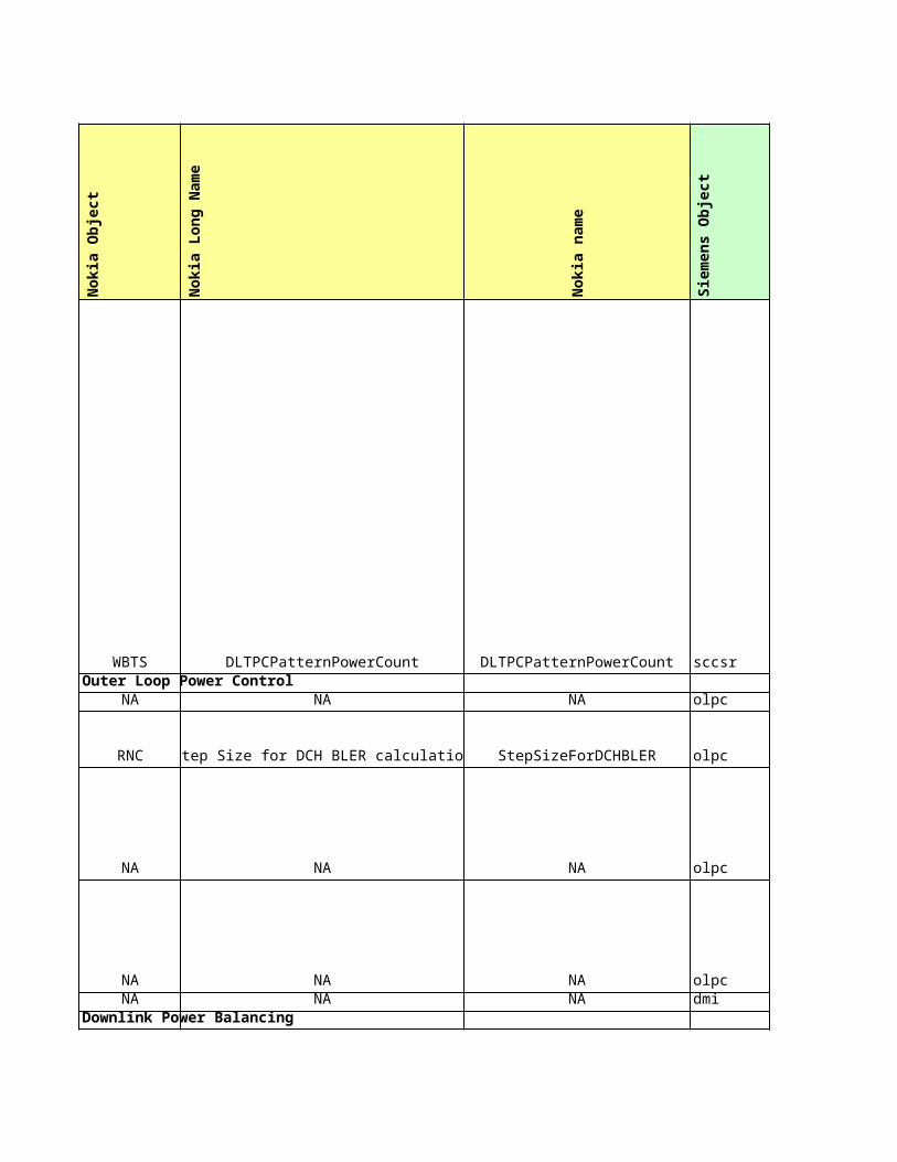
This parameter defines whether Power Balancing is used or not.
When RNC calculates a new reference power for base stations, it is not updated to the base stations if it does not differ from the existing reference power in the base stations at least by a value defined by this parameter. Setting this parameter to a small value, such as 1dB, causes the new reference power to be updated to the related base stations every time the measurement reports arrive and setting it to a larger value causes the reference power to be updated more seldom. In other words, this parameter can be used to limit the amount of messaging traffic related to reference power updates.
This parameter defines the period during which the DL transmitted power has to be corrected to the reference power. Setting this parameter to a small value makes power balancing faster, whereas setting it to a large value makes it slower.
This parameter defines the convergence rate (towards the reference power) used for the associated Adjustment Period. Large values cause underestimations to power corrections. If the value is zero, power is corrected to the DL reference power.
Defines a time period (in terms of a number of slots) during which the accumulated power adjustment will be no more than 1dB. This value does not include the DL inner loop PC adjustment. A small amount of slots grants quick response times for power balancing but may cause overestimations.
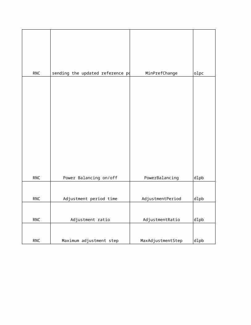
Sie
me
ns
De
sc
rip
tio
n
Threshold value for new update
Step size of the outer loop power control
Lower threshold of SIR error
Upper threshold of SIR errorFilter coefficient for call trace measurements for SIR error
The DL TPC pattern 01 count IE in NBAP:Cell Setup Request message contains the value of the parameter n which is used for determining the DL TPC pattern on Radio Links marked with "first LS" by the First RLS indicator IE before UL synchronisation is achieved
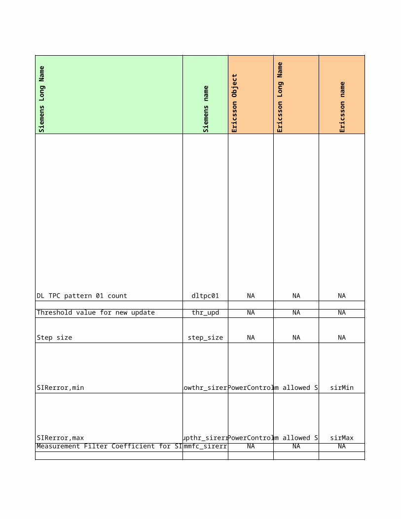
Update threshold for new Pref.
This Flag is used to switch the PB feature ON (“True”) and OF
Indicates the frequency of power adjustments
0 -> 0.001 -> 0.01…100 -> 1.00
Defines a time period in which the accumulated power adjustment will have a maximum value of 1dB.
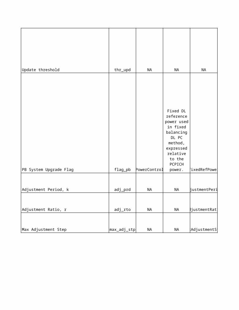
Eri
cs
so
n D
es
cri
pti
on
NA
The minimum allowed SIR target.
-82: -8,2 dB -81: -8,1 dB..173: 17,3 dB
The maximum allowed SIR target.
-82: -8,2 dB -81: -8,1 dB..173: 17,3 dB
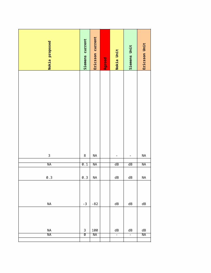
NA
NA
NA
NA
Fixed DL reference power used in fixed balancing DL PC method, expressed relative to the PCPICH power.
Unit: 0.5 decibels (dB)Resolution: 1
1 : -35.0 dB2 : -34.5 dB3 : -34.0 dB4 : -33.5 dB5 : -33.0 dB6 : -32.5 dB...65 : -3.0 dB...70 : -0.5 dB71 : 0.0 dB72 : 0.5 dB...101 : 15.0 dB
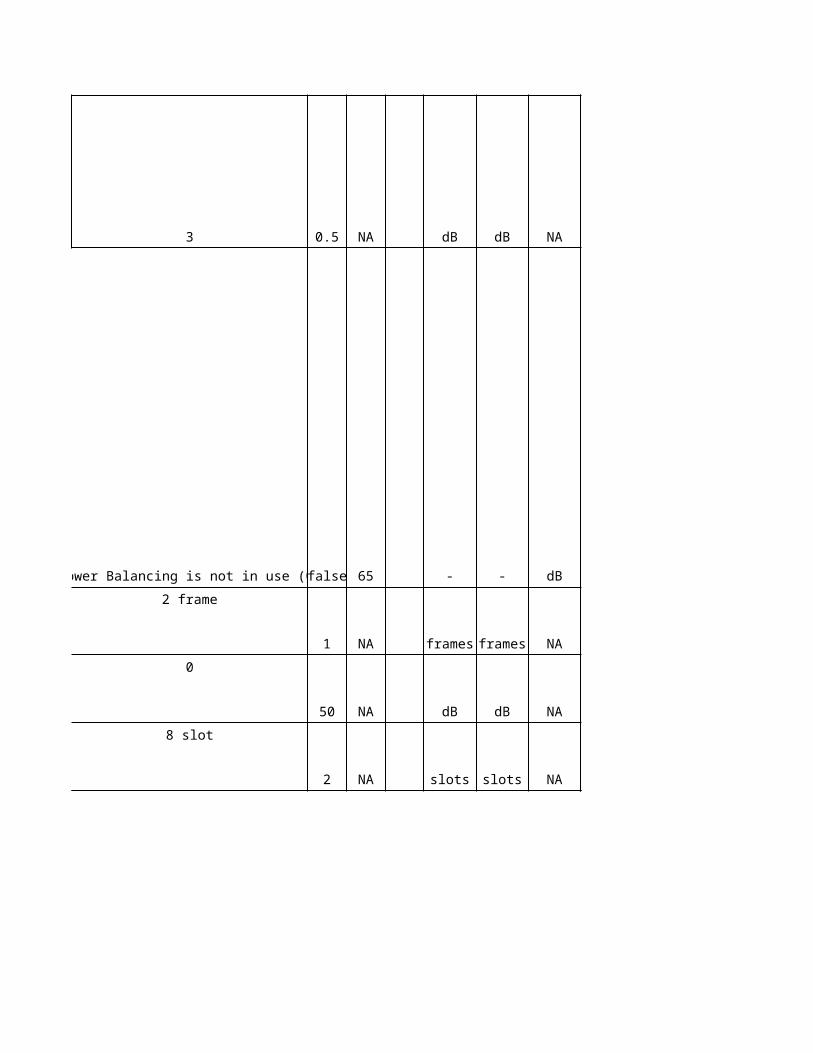
No
kia
Ob
jec
t
No
kia
Lo
ng
Na
me
No
kia
na
me
Sie
me
ns
Ob
jec
t
Sie
me
ns
Lo
ng
Na
me
WCEL HCS priority level for a cell HCS_PRIO cell hcs HCS_PRIO
WCEL Use of HCS UseOfHCS cell hcs HCS_PRIO
HOPI Cell Re-selection HCS Priority AdjiHCSpriority euc HCS_PRIO
HOPS Cell Re-selection HCS Priority AdjsHCSpriority euc HCS_PRIO
HOPG Cell Re-selection HCS Priority AdjgHCSpriority egc HCS_PRIO
WCEL Quality threshold level for HCS QHCS cell hcs QHCS
HOPI Cell Re-selection HCS ThresholdAdjiHCSthreshold euc QHCS
HOPS Cell Re-selection HCS ThresholdAdjsHCSthreshold euc QHCS
HOPG Cell Re-selection HCS ThresholdAdjgHCSthreshold egc QHCS
NA NA NA cell hcs Penalty_Time
HOPI Cell Re-selection Penalty Time AdjiPenaltyTime euc Penalty_Time
HOPS Cell Re-selection Penalty Time AdjsPenaltyTime euc Penalty_Time
HOPG Cell Re-selection Penalty Time AdjgPenaltyTime egc Penalty_Time
NA NA NA cell hcs Temporary_ Offset1
HOPI Cell Re-selection Temporary Offset 1AdjiTempOffset1 euc Temporary_ Offset1
HOPSCell Re-selection Temporary Offset 1AdjsTempOffset1 euc Temporary_ Offset1
HOPGCell Re-selection Temporary Offset 1AdjgTempOffset1 egc Temporary_ Offset1
HOPI Cell Re-selection Temporary Offset 2AdjiTempOffset2 cell hcs Temporary_ Offset2
HOPSCell Re-selection Temporary Offset 2AdjsTempOffset2 cell hcs Temporary_ Offset2
WCELEvaluating period for amount of cell reselectionsTCrmax cell hcs TCrmax
WCELHysteresis to revert from UE high-mobility measurementsTCrmaxHyst cell hcs TCrmaxHyst
WCELMaximum number of cell reselections NCr cell hcs NCR
NA NA NA cell hcs Ssearch,HCS flag
WCEL S searchHCS SsearchHCS cell hcs Ssearch,HCS
NA NA NA cell hcs SHCS,RAT flag
WCELThreshold for inter-RAT measurement rules in HCSSHCS_RAT cell hcs SHCS,RAT
Sie
me
ns
na
me
Eri
cs
so
n O
bje
ct
Eri
cs
so
n L
on
g N
am
e
Eri
cs
so
n n
am
e
No
kia
pro
po
se
d
Sie
me
ns
cu
rre
nt
Eri
cs
so
n c
urr
en
t
pri_hcs NA NA NA NA
pri_hcs NA NA NA NA
pri_hcs NA NA NA - - NA
pri_hcs NA NA NA - - NA
pri_hcs NA NA NA - - NA
qhcs NA NA NA -24 NA
qhcs NA NA NA - - NA
qhcs NA NA NA - - NA
qhcs NA NA NA - - NA
tm_pnlt NA NA NA NA 0 NA
tm_pnlt NA NA NA 0 - NA
tm_pnlt NA NA NA 0 - NA
tm_pnlt NA NA NA 0 - NA
offset1_temp NA NA NA NA 6 NA
R99:1HSDPA:0
R99:1HSDPA:0
1 carrier site: Not used (0)2 carrier site:
Used (1)R99:1
HSDPA:0
R99:0HSDPA:10
offset1_temp NA NA NA 6 - NA
offset1_temp NA NA NA 6 - NA
offset1_temp NA NA NA 6 - NA
offset2_temp NA NA NA 3 3 NA
offset2_temp NA NA NA 3 3 NA
tcrmax NA NA NA 0 0 NA
tcrmax_hyst NA NA NA 0 0 NA
ncr NA NA NA 8 8 NA
flag_sshcs NA NA NA NA true NA
ss_hcs NA NA NA 11 11 NA
flag_shcsrat NA NA NA NA true NA
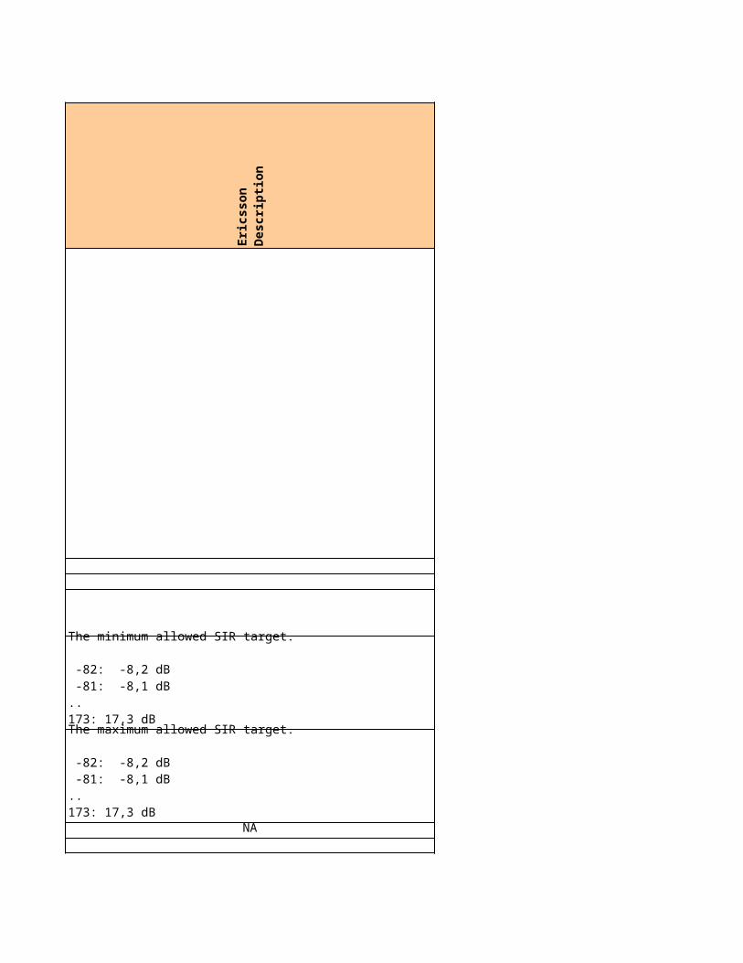
shcs_rat UtranCell sHcsRat sHcsRat 1 1 3
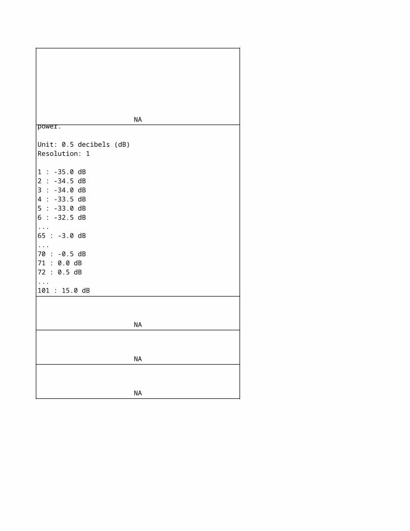
Ag
ree
d
No
kia
Un
it
Sie
me
ns
Un
it
Eri
cs
so
n U
nit
- - NA
NA
- - NA
- - NA
- - NA
dB - NA
- - NA
- - NA
- - NA
s s NA
s s NA
s s NA
s s NA
dB dB NA
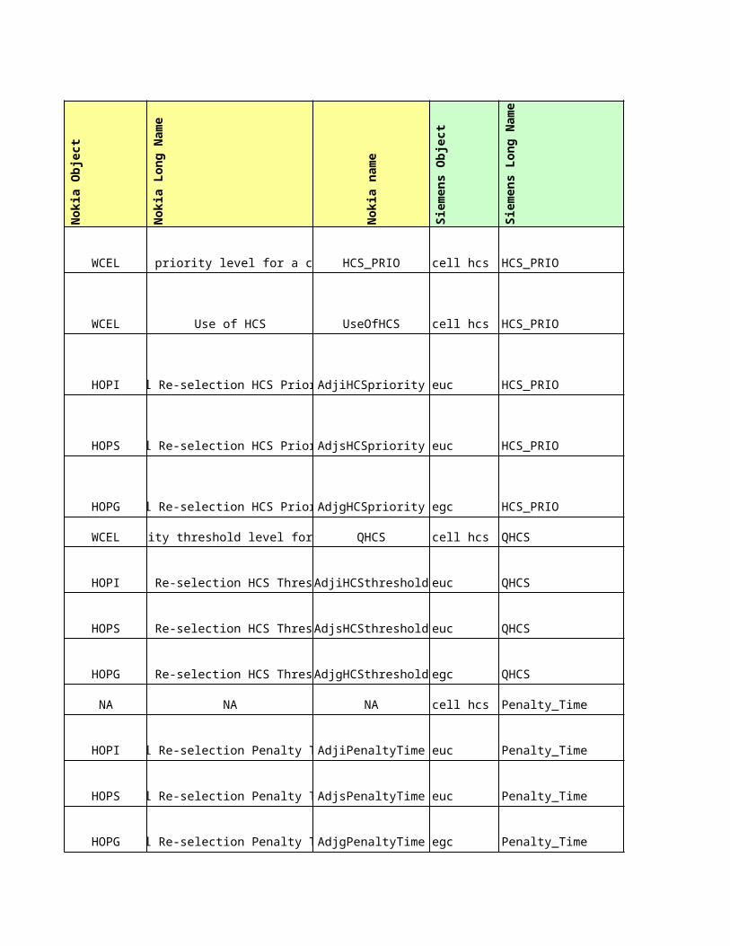
dB dB NA
dB dB NA
dB dB NA
dB dB NA
dB dB NA
s s NA
s s NA
0 0 NA
0 0 NA
dB dB NA
0 0 NA
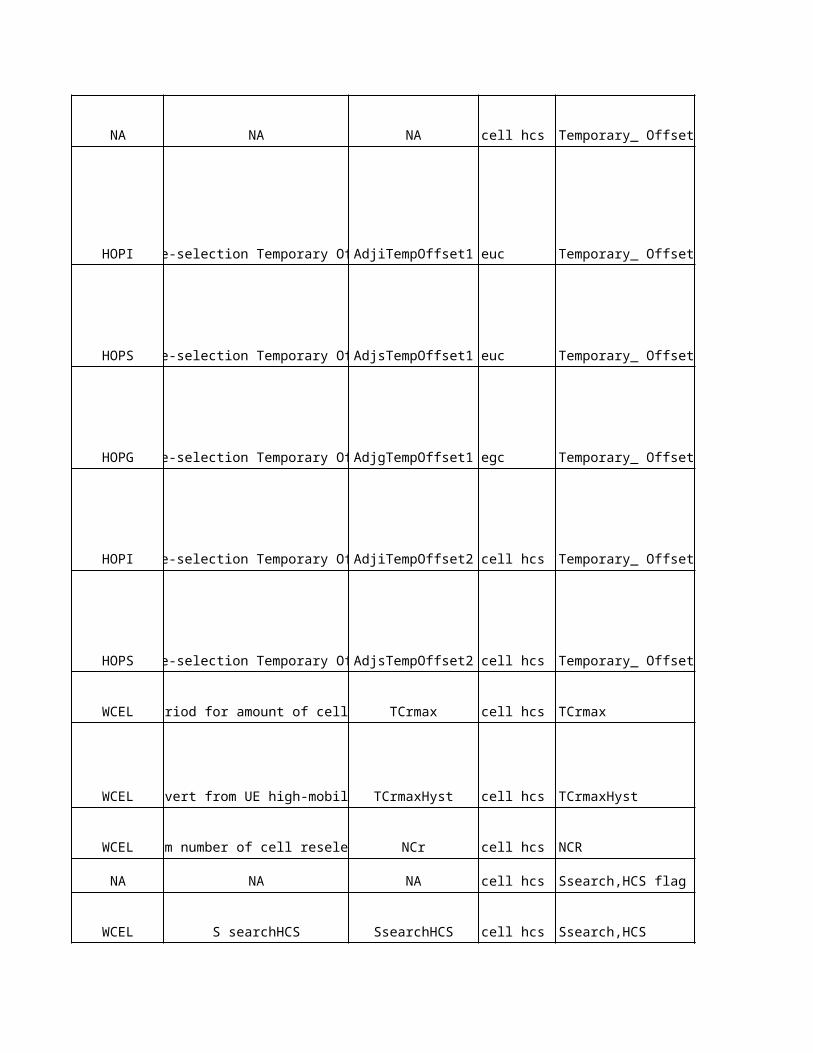
dB dB dB
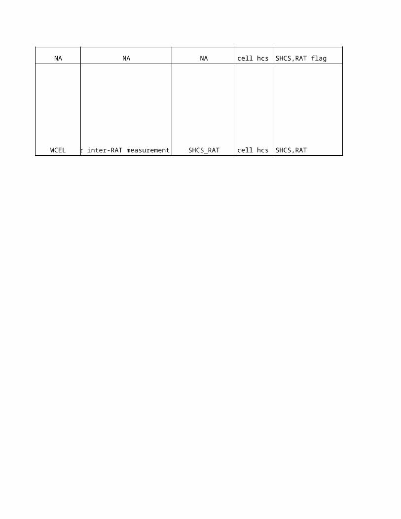
No
kia
De
sc
rip
tio
n
NA
NA
This parameter defines the HCS priority level for a cell. Value 0 indicates the lowest HCS priority and value 7 indicates the highest HCS priority. This parameter is not needed if HCS is not used.
This parameter indicates whether the serving cell belongs to a Hierarchical Cell Structure (HCS), or not.
Defines the priority level of the inter-frequency neighbour cell in the hierarchical cell re-selection procedure. 0 indicates the lowest HCS priority and 7 indicates the highest HCS priority. Lower HCS priority values are meant for larger macro cells and higher HCS priority values are meant for smaller pico/micro cells.
Defines the priority level of the neighbouring cell in the hierarchical cell re-selection procedure. 0 indicates the lowest HCS priority and 7 indicates the highest HCS priority. Lower HCS priority values are meant for larger macro cells and higher HCS priority values are meant for smaller pico/micro cells.
Defines the priority level of the GSM neighbour cell in the hierarchical cell re-selection procedure. 0 indicates the lowest HCS priority and 7 indicates the highest HCS priority. Lower HCS priority values are meant for larger macro cells and higher HCS priority values are meant for smaller pico/micro cells.
Quality threshold level (CPICH Ec/No) for applying prioritised hierarchical cell re-selection for a cell. Needed only if HCS is used.
Defines the threshold level which must be exceeded by the CPICH Ec/No of the inter-frequency neighbour cell before the hierarchical cell re-selection becomes possible.
Defines the threshold level which must be exceeded by the CPICH Ec/No of the neighbouring cell before the hierarchical cell re-selection becomes possible.
Defines the threshold which must be exceeded by the RSSI measurement result of the GSM neighbour cell before the hierarchical cell re-selection becomes possible.
Defines the time period during which the Temporary Offset 1/2 is applied in the cell re-selection procedure for the inter-frequency neighbour cell.
Defines the time period during which the Temporary Offset 1/2 is applied in the cell re-selection procedure for the neighbour cell in question.
Determines the time period during which the Temporary Offset 1 is applied in the cell re-selection procedure for the GSM neighbour cell in question.
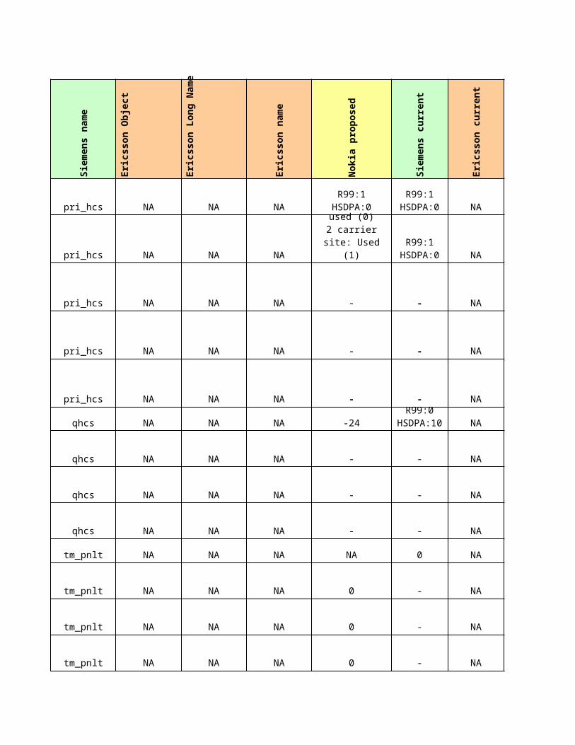
NA
NA
This parameter is used in the cell ranking between GSM and WCDMA cells when the inter-frequency neighbour cell has the same HCS priority level as the serving cell. If the neighbour cell has a different HCS priority level, the offset value is applied for the HCS cell re-selection between GSM and WCDMA cells. The offset is subtracted (during Penalty Time) from the measured CPICH RSCP of the inter-frequency neighbour cell. The alternative values are the following: 3 dB, 6 dB, 9 dB, 12 dB, 15 dB, 18 dB, 21 dB and 'Infinity'.
This parameter is used in the cell ranking between GSM and WCDMA cells when the neighbour cell has the same HCS priority level as the serving cell. If the neighbour cell has a different HCS priority level, the offset value is applied for the HCS cell re-selection between GSM and WCDMA cells. The offset is subtracted (during Penalty Time) from the measured CPICH RSCP of the neighbour cell. The alternative values are the following: 3 dB, 6 dB, 9 dB, 12 dB, 15 dB, 18 dB, 21 dB and 'Infinity'.
This parameter is used in the cell ranking between GSM and WCDMA cells when the GSM neighbour cell has the same HCS priority level as the serving cell. If the GSM neighbour cell has a different HCS priority level, the offset value is applied for the HCS cell re-selection between GSM and WCDMA cells. The offset is subtracted (during Penalty Time) from the measured RSSI level of the GSM neighbour cell. The alternative values are the following: 3 dB, 6 dB, 9 dB, 12 dB, 15 dB, 18 dB, 21 dB and 'Infinity'.
This parameter is used in the cell ranking between WCDMA cells when the inter-frequency neighbour cell has the same HCS priority level as the serving cell. If the neighbour cell has a different HCS priority level, the offset value is applied for the HCS cell re-selection between WCDMA cells. The offset is subtracted (during Penalty Time) from the measured CPICH Ec/No of the inter-frequency neighbour cell. The alternative values are the following: 2 dB, 3 dB, 4 dB, 6 dB, 8 dB, 10 dB, 12 dB and 'Infinity'.
This parameter is used in the cell ranking between WCDMA cells when the neighbour cell has the same HCS priority level as the serving cell. If the neighbour cell has a different HCS priority level, the offset value is applied for the HCS cell re-selection between WCDMA cells. The offset is subtracted (during Penalty Time) from the measured CPICH Ec/No of the neighbour cell. The alternative values are the following: 2 dB, 3 dB, 4 dB, 6 dB, 8 dB, 10 dB, 12 dB and 'Infinity'.
The duration for evaluating the allowed amount of cell reselections. If the number of cell reselections during the time period defined by TCrmax exceeds Ncr, high mobility has been detected. Needed only if HCS is used.
Cell reselection hysteresis for reverting from UE high-mobility measurements. The additional time period before UE reverts to low-mobility measurements. When the number of cell reselections during the time period defined by TCrmax no longer exceeds NCr, UE continues measurements during the time period defined by TCrmaxHyst. Needed only if HCS is used.
This parameter defines the maximum number of cell reselections. If the number of cell reselections during the TCrmax time period exceeds the value of NCr, high mobility has been detected. Needed only if HCS is used. Not used if TCrmax equals 'not used'
Threshold for intra- and interfrequency measurement rules in HCS. Below this limit in the serving cell, the UE initiates measurements of all intra and inter-frequency neighbouring cells of the serving cell.
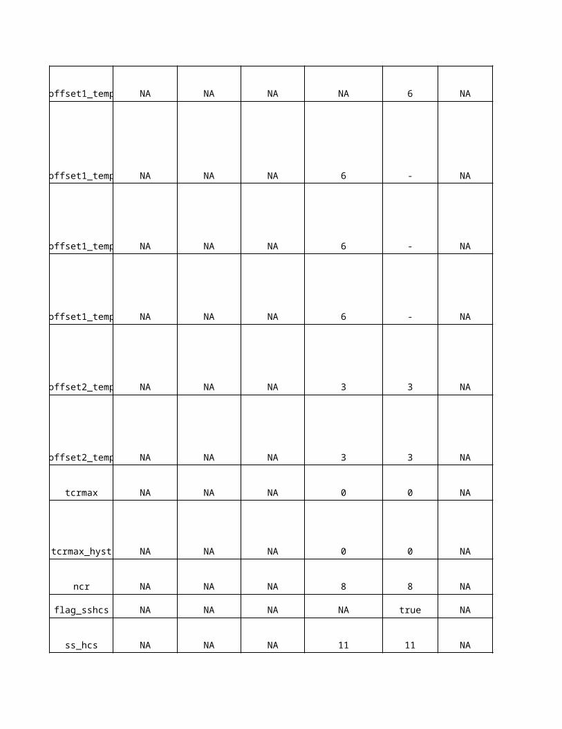
The RAT specific threshold for inter-RAT measurement rules. Needed only if HCS is used.
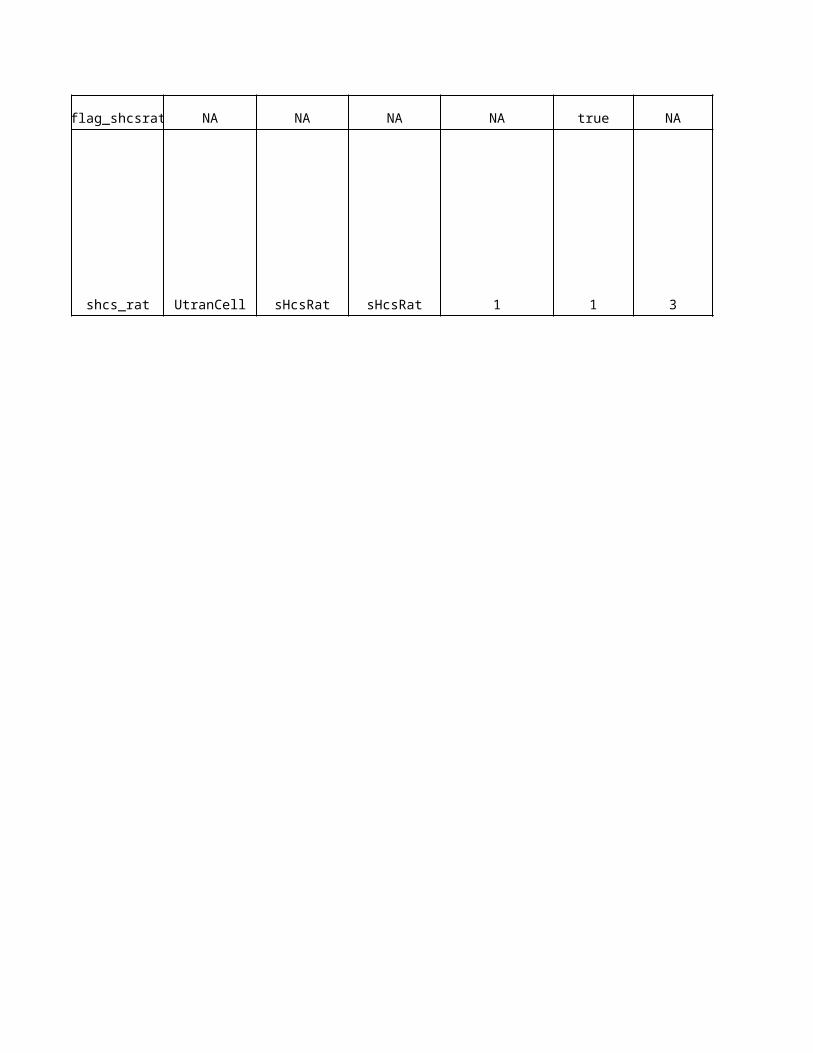
Sie
me
ns
De
sc
rip
tio
n
This specifies the HCS priority level
This specifies the HCS priority level
This specifies the HCS priority level
This specifies the HCS priority level
This specifies the HCS priority level
Specifies the quality threshold levels for applying prioritised hierarchical cell re-selection.Value 0 means not used
Specifies the quality threshold levels for applying prioritised hierarchical cell re-selection.Value 0 means not used
Specifies the quality threshold levels for applying prioritised hierarchical cell re-selection.Value 0 means not used
Specifies the quality threshold levels for applying prioritised hierarchical cell re-selection.Value 0 means not used
Specifies the time duration for which the Temporary_Offset is applied for the cellValue 0 means not used
Specifies the time duration for which the Temporary_Offset is applied for the cellValue 0 means not used
Specifies the time duration for which the Temporary_Offset is applied for the cellValue 0 means not used
Specifies the time duration for which the Temporary_Offset is applied for the cellValue 0 means not used
Specifies the offset applied to the H and R criteria for the cell for the duration of Penalty_Time.It is used for FDD cells in case the quality measure is set to CPICH RSCP
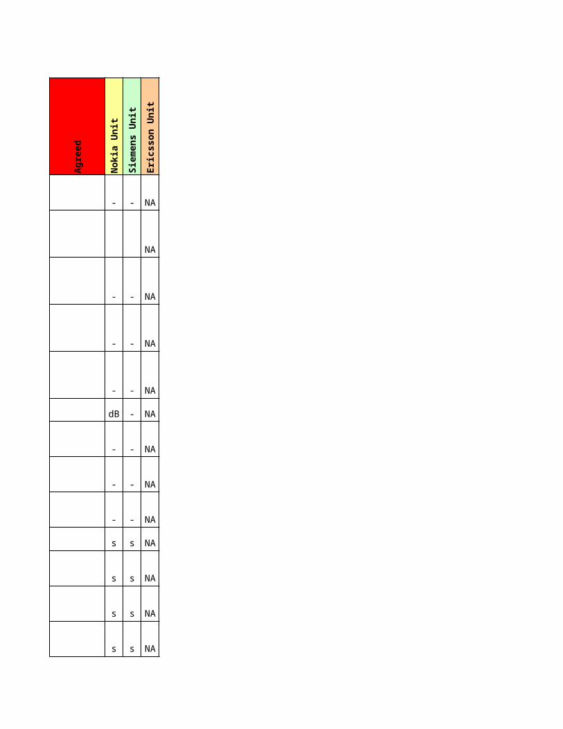
Specifies the duration for evaluating allowed amount of cell reselection
Specifies the duration for evaluating allowed amount of cell reselection
Maximum number of cell reselections.
Specifies whether the parameter appears in SIB 3 of System Information
Specifies whether the parameter appears in SIB 3 of System Information
Specifies the offset applied to the H and R criteria for the cell for the duration of Penalty_Time.It is used for FDD cells in case the quality measure is set to CPICH RSCP
Specifies the offset applied to the H and R criteria for the cell for the duration of Penalty_Time.It is used for FDD cells in case the quality measure is set to CPICH RSCP
Specifies the offset applied to the H and R criteria for the cell for the duration of Penalty_Time.It is used for GSM cells in case the quality measure is set to CPICH RSCP
Specifies the offset applied to the H and R criteria for the cell for the duration of Penalty_Time.It is used for GSM cells in case the quality measure is set to CPICH ECNO
Specifies the offset applied to the H and R criteria for the cell for the duration of Penalty_Time.It is used for GSM cells in case the quality measure is set to CPICH ECNO
This threshold is used in the measurement rules for cell re-selection when HCS is used. It specifies the limit for Srxlev in the serving cell below which the UE shall initiate measurements of all neighbouring cells of the serving cell.
This threshold is used in the measurement rules for cell re-selection when HCS is used. It specifies the RAT (GSM) specific threshold in the serving cell used in the inter-RAT measurement rules.
Eri
cs
so
n D
es
cri
pti
on
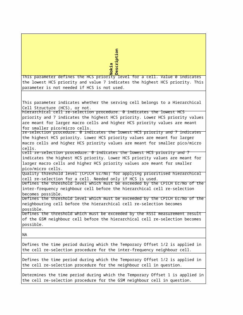
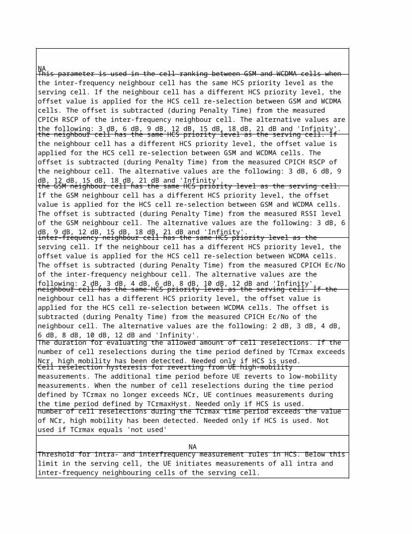
RAT specific threshold in the serving cell used in the inter-RAT measurement rules. This parameter is used by the UE to decide when to start GSM measurements for cell reselection, if the serving cell is indicated to belong to a Hiearachical Cell Structure (HCS)GSM measurements in idle mode and state CELL_FACH are started by the UE when RSCP <= qRxLevMin + sHscRat. If sHcsRat is set to a negative value, this will be interpreted as 0 by the UE (according to 3GPP TS 25.331).Unit: 1 dBResolution: 2
No
kia
Ob
jec
t
No
kia
Lo
ng
Na
me
- -
WCEL Cell maximum transmission power
WCEL Target for transmitted power
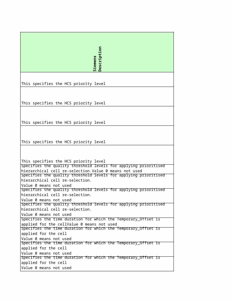
WCEL Frame timing offset of a cell
- -
- -
- -
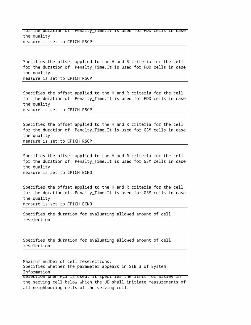
RNC Network Mode of Operation
RNC Attach-detach allowed
RNC T3212
WCEL T312 for connected mode
WCEL N312 for connected mode
WCEL T313
WCEL N313
WCEL N315
NA NA
RNC T305RNC T302
RNC N302
RNC T307
NA NA
WCEL Transmission power of the primary CPICH channel
WCEL Transmission power of the primary CCPCH channel
WCEL Transmission power of the primary SCH channel
WCEL Transmission power of the secondary SCH channel
WCEL Transmission power of the AICH channel
WCEL Tx power of S-CCPCH for PCH/FACH(s) or standalone FACH(s)

WCEL Transmission power of the PICH channel
WCEL UTRAN DRX cycle length
NA NA
NA NA
RNC T316
RNC T317
WCEL T300
WCEL N300
RNC T309
RNC T314
WCEL T315
WCEL Service Area Code for SABNA NA
NA NA
NA NA
RNC T304RNC N304RNC T308
NA NA
No
kia
na
me
Sie
me
ns
Ob
jec
t
Sie
me
ns
Lo
ng
Na
me
Sie
me
ns
na
me
Eri
cs
so
n O
bje
ct
- cell iub UARFCN Uplink uarfcn NA
PtxCellMax cell iub max_dltp UtranCell
PtxTarget cell iub max_dltp UtranCell
Maximum DL Transmission Power
Maximum DL Transmission Power
Tcell cell iub T_Cell t_cell UtranCell
- cell iub SAC sac UtranCell
- cell iub RAC rac UtranCell
- cell iub LAC lac UtranCell
PS_NMO cell iub nwom UtranCell
CSAttachDetachAllowed cell iub Attach-Detach atdt UtranCell
CS_T3212 cell iub tmr_cspu UtranCell
T312Conn cell iub T312 t312 NA
N312Conn cell iub N312 n312 NA
T313 cell iub T313 t313 NA
N313 cell iub N313 n313 NA
N315 cell iub N315 n315 NA
NA cell iub URA Identity id_ura NA
Network Operator Mode
CS periodic update timer
T305 cell iub tpcu RrcT302 cell iub T302 t302 NA
N302 cell iub N302 n302 NA
T307 cell iub T307 t307 NA
NA cell iub sc_pcpi NA
PtxPrimaryCPICH cell iub pwr_pcpit PowerControl
T305(Periodical cell update Timer)
Primary CPICH scrambling code
Primary CPICH Tx power
PtxPrimaryCCPCH cell iub BCH power offset po_bch PowerControl
PtxPrimarySCH cell iub po_psch UtranCell
PtxSecSCH cell iub po_ssch UtranCell
PtxAICH ulcc AICH power offset po_aich Rach
PtxSCCPCH1 ulcc PCH power offset po_pch Pch
Primary SCH power offset
Secondary SCH power offset
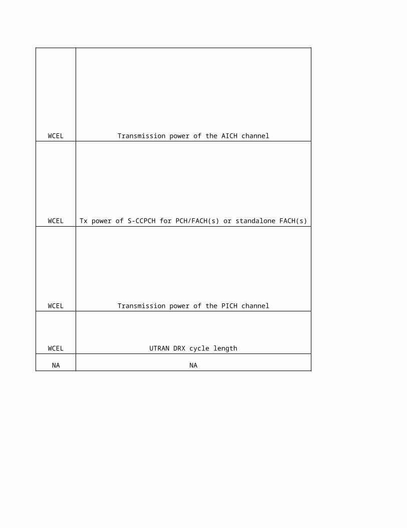
PTxPICH ulcc PICH power offset po_pich Pch
UTRAN_DRX_length cell iub dclc_utran Sid
NA cell iub Poffset poffset
NA cell iub Max power value pwval_maxPowerControl
T316 cell iub T316 t316 NA
T317 cell iub T317 t317 NA
T300 cell iub T300 t300 NA
N300 cell iub N300 n300 NA
UTRAN DRX Cycle Length
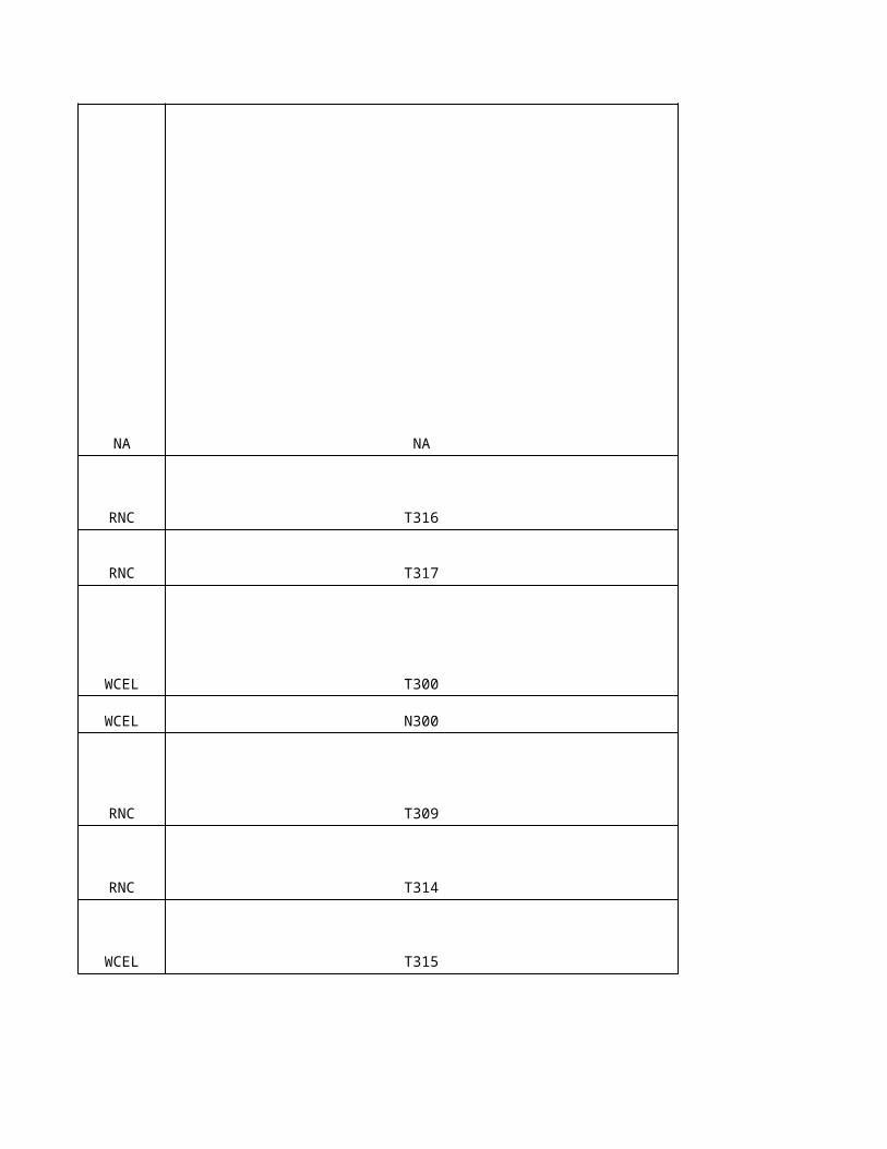
T309 cell iub T309 t309 NA
T314 cell iub T314 t314 NA
T315 cell iub T315 t315 NA
SACB cell iub SACBC sac_cbs NANA cell iub PLMN Value Tag plmn_vt NA
NA cell iub po_thra NA
NA cell iub flag_asup NA
T304 cell iub T304 t304 NAN304 cell iub N304 n304 NAT308 cell iub T308 t308 NA
NA cell iub Secondary Scrambling Code sscode NA
Power offset for threshold A
Alarm suppression flag
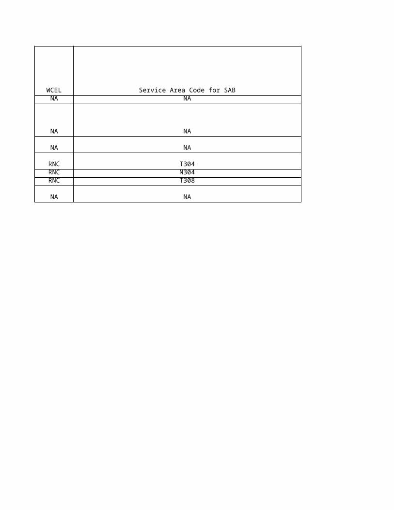
Eri
cs
so
n L
on
g N
am
e
Eri
cs
so
n n
am
e
No
kia
pro
po
se
d
Sie
me
ns
cu
rre
nt
Eri
cs
so
n c
urr
en
t
Ag
ree
d
No
kia
Un
it
Sie
me
ns
Un
it
Eri
cs
so
n U
nit
NA NA - - NA - -
43 43 400 dBm dBm
42 43 400 dBm dBm
Maximum transmission power is maximum power for
all downlink channels
added together,
that is allowed tobe used
simultaneously in a
cell.
maximumTransmissio
nPower
Maximum transmission power is maximum power for
all downlink channels
added together,
that is allowed tobe used
simultaneously in a
cell.
maximumTransmissio
nPower
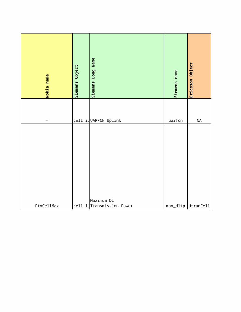
tCell - - - -
sac - - - -
rac - - - -
lac - - - -
Timing delay used for defining
start of SCH,
CPICH and the DL
scrambling codes.
Service Area Code
of the service
area that a cell
belongs to.
Routing Area Code of a routing
area.
The Location
Area Code of the
external RNC cell, used by
UTRAN to page
mobiles on request from the
CSCN.
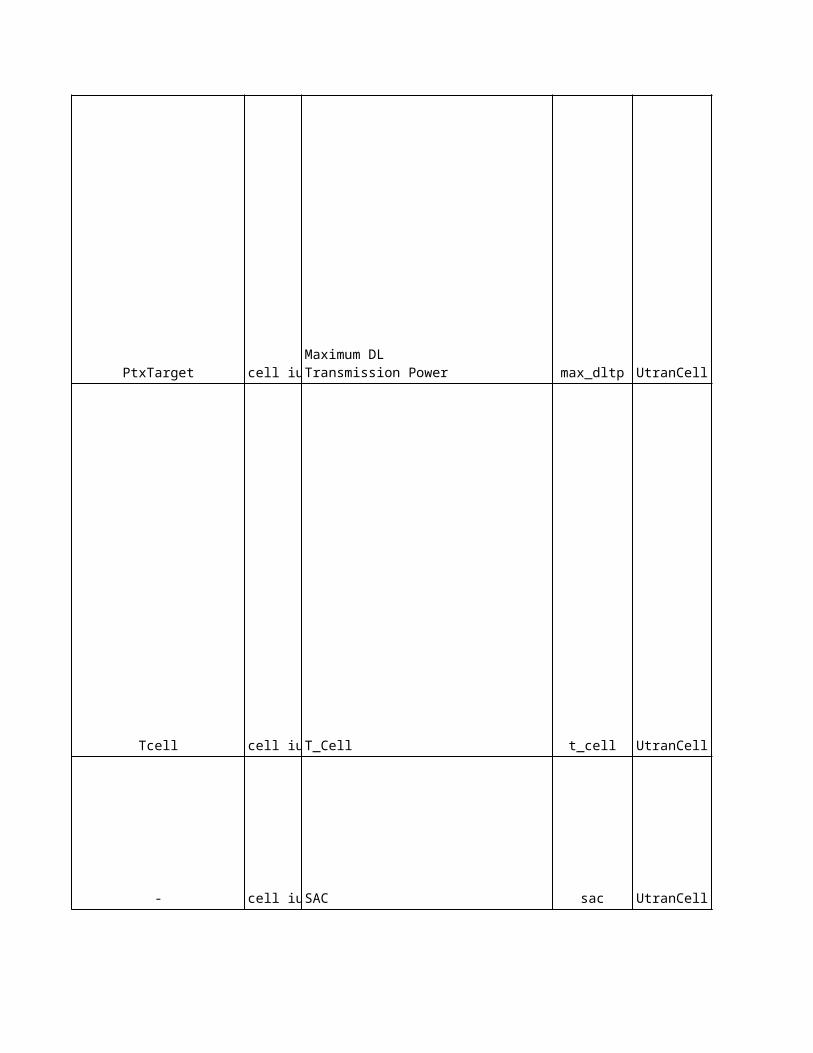
nmo Network Mode of Operation II (1) md2 1 - -
att
IMSI attach/detach allowed (1)
mnd 1 - -
t3212 49 294 10 decihour(6min) min
NA NA 6 6 NA s s
NA NA 1 1 NA - -
NA NA 3 3 NA s s
NA NA 20 20 NA - -
NA NA 1 1 NA - -
NA NA NA - NA - -
Network operation mode that indicates whether the Gs
interface between
the SGSN and
MSC/VLR is installed.
Indicates to the UE whether
IMSI attach/deta
ch is allowed.
Periodic update
timer for LA update.
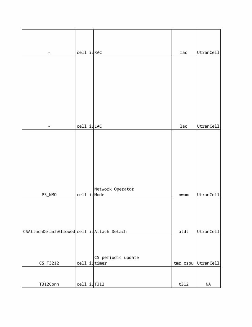
t305 30 30 3 min minNA NA 1000 1000 NA ms ms
NA NA 7 7 NA - -
NA NA 30 30 NA s s
NA NA NA - NA - -
33 33 33 dBm dBm
Timer for the time in
UE between periodic
cell updates.
Default primary CPICH
power. If the primary
CPICH power is
not provided
from DRNC,
DPCCH_Power_Offse
t is calculated using the
parameter.
Resolution 1 dBm.
pcpichPowerDefault
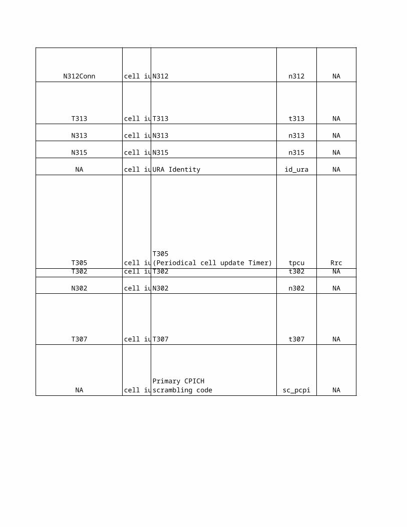
pO3 -5 -3 dB dB
-3 -3 12 dB dB
-3 -3 -18 dB dB
aichPower -8 -4 -6 dB dB
pchPower 0 -3 -4 dB dB
Power offset for the pilot
bits.
Primary SCH
power, relative to
the primaryCpichPower
value.primarySch
Power
primarySchPower
Primary SCH
power, relative to
the primaryCpichPower
value.
AICH power
Maximum power to
be used for transmitting the PCH
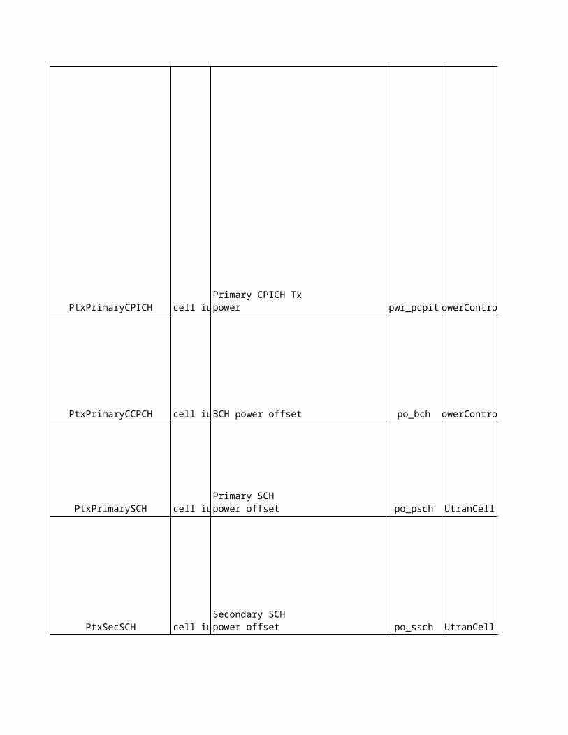
pichPower -8 -6 -7 dB dB
320 ms (5) 6 1 - -
NA NA NA 16 NA dB dB
NA 6 65 dB dB
NA NA 30(3) 30 NA s s
NA NA 180(4) 180 NA s s
NA NA 4000 4000 NA ms ms
NA NA 3 3 NA - -
PICH power
noOfMaxDrxCycles
Paging notification duration.
fixedPowerDl
Fixed DL power used in fixed DL
PC method.
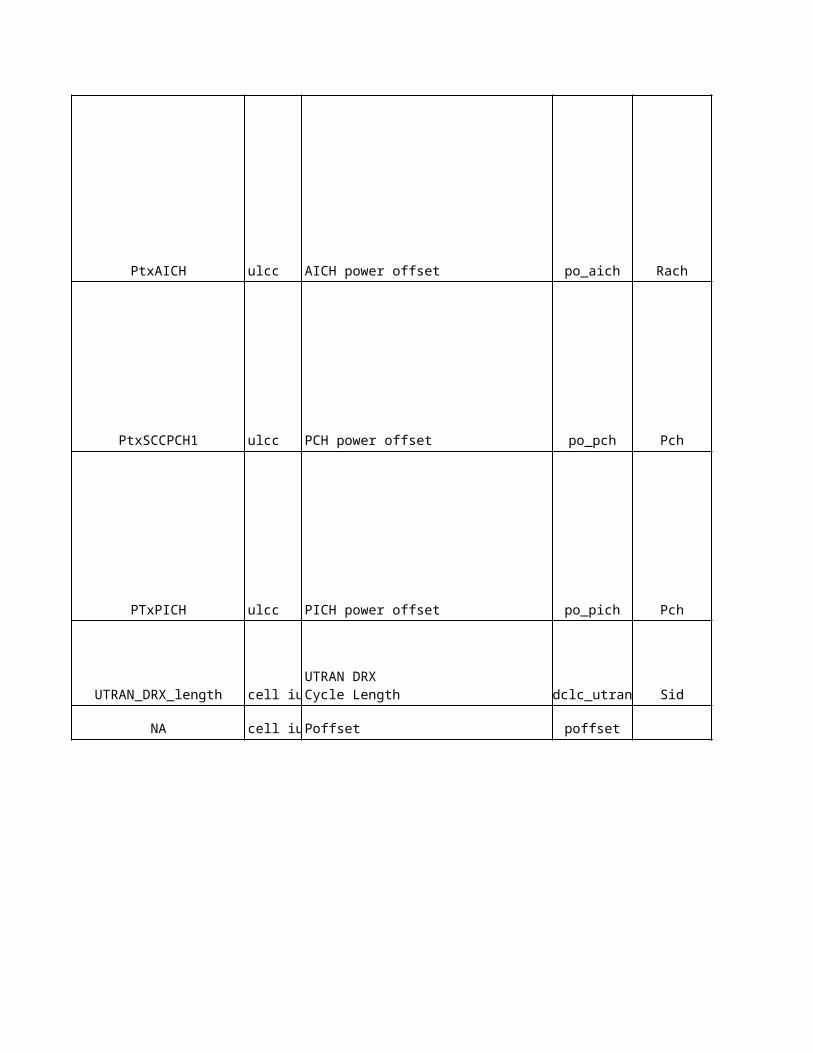
NA NA 5 5 NA s s
NA NA 0 6 NA s s
NA NA 180(4) 180 NA s s
NA NA - - NA - -NA NA NA - NA - -
NA NA NA 3 NA dB dB
NA NA NA off NA - -
NA NA 1000 NA ms msNA NA 2 1 NA - -NA NA 40(0) 40 NA ms ms
NA NA NA - NA - -
2000 ms (4)
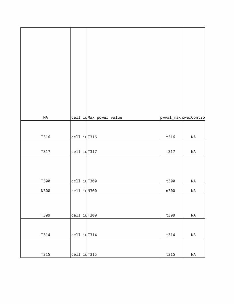
No
kia
De
sc
rip
tio
n
-
This parameter defines the maximum transmission power of the cell. The maximum transmission power is the maximum value for the linear sum of the power of all downlink physical channels that is allowed to be used in a cell. The maximum transmission power of the cell is the minimum of the two parameters: PtxCellMax and MaxDLPowerCapability (the maximum BTS power capability). The RNC signals the BTS the minimum value as the maximum transmission power in Maximum Transmission Power IE (TS 25.433). The RNC uses the minimum value as the maximum transmission power of the cell. If HSDPA static resource allocation is active, the value of the PtxMaxHSDPA parameter added with the value of the PtxTargetHSDPA parameter must not exceed the cell maximum transmission power defined by the minimum of the following parameters: PtxCellMax and MaxDLPowerCapability. Otherwise Rthe NC internally limits the HSDPA power.
This is the target value for total transmitted power in a cell. A real-time Radio Access Bearer is not admitted, if the estimated non-controllable power exceeds this threshold. Default value should be 3dB below the Cell maximum transmission power.
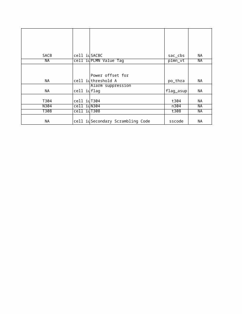
-
-
-
Each cell in a BTS uses a System Frame Number (SFN) counter, which is the BTS Frame Number (BFN) counter delayed by a number of chips defined by the value of Tcell.
Tcell is used for defining the start of SCH, CPICH, Primary CCPCH and DL Scrambling Code(s) in a cell relative to BFN. The main purpose is to avoid having overlapping SCHs in different cells belonging to the same BTS. An SCH burst is 256 chips long.
The values can be chosen as follows: 0 chips for the 1st cell of the BTS, 256 chips for the 2nd cell of the BTS, 512 chips for the 3rd cell of the BTS, etc.
Note: Changing the parameter value will start the cell shutdown procedure in the BTS.
Nokia BTS shall control HSDPA cell allocation so that only cells belonging to the same Tcell group are allocated to the same MAC-hs entity.
Group 1: Tcell values 0 (0 chips), 1 (256 chips) and 2 (512 chips) Group 2: Tcell values 3 (768 chips), 4 (1024 chips) and 5 (1280 chips) Group 3: Tcell values 6 (1536 chips), 7 (1792 chips) and 8 (2048 chips) Group 4: Tcell value 9 (2304 chips)
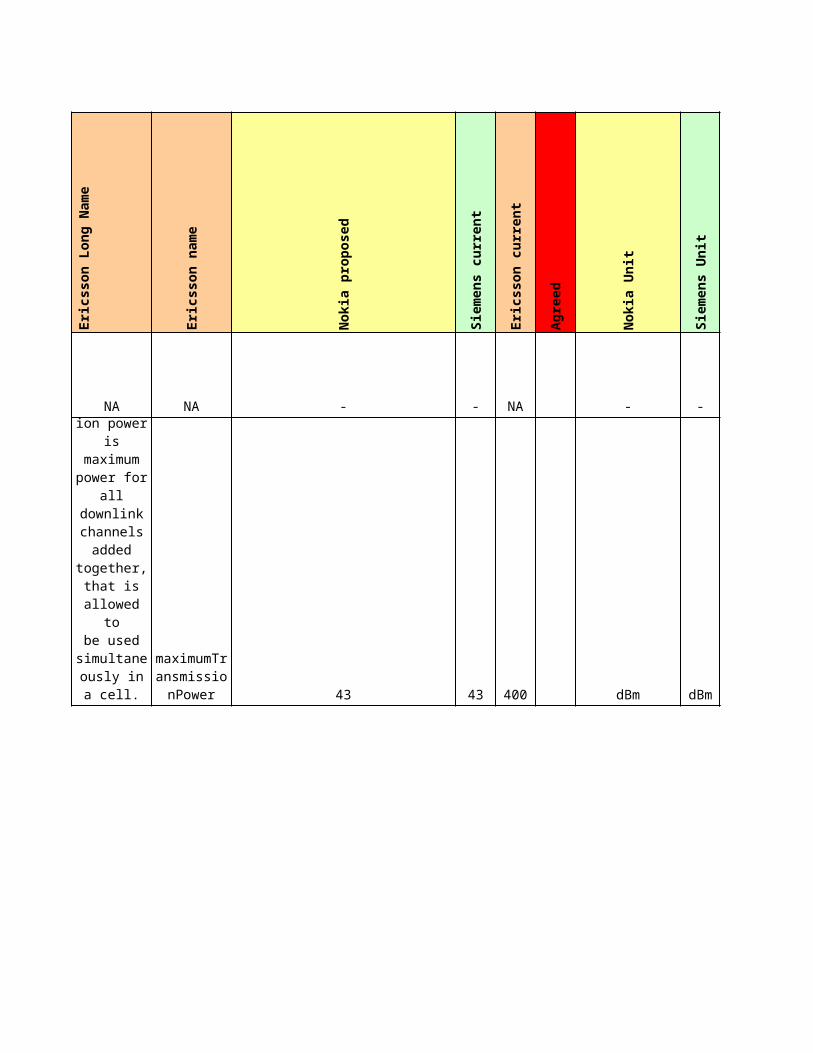
The radio link failure timer (MS timer).
NA
In Operation Mode I it is possible to have combined CS and PS side paging via SGSN. In Operation Mode II the combined paging procedure is not possible (and neither are combined attach procedures). Used only for the PS domain. NMO is part of PS CN domain specific NAS System information in System Information Block 1.
Defines whether IMSI attach and detach are allowed or not. 0 = MSs shall not apply IMSI attach and detach procedure, 1 = MSs shall apply IMSI attach and detach procedure. Parameter is given only for CS domain. (Part of CS domain specific NAS System information in SIB1.)
The timeout value, in decihours (6 min), for periodic location updating. Given only for CS domain. (Part of CS domain specific NAS System information in SIB1). The value 0 is used for an infinite timeout value, that is, periodic location updating is not used.
The timer for supervising successful establishment of a physical channel (this MS timer is used in connected mode).
This parameter defines the maximum number of "in sync" indications received from L1 during the establishment of a physical channel (MS counter used in connected mode).
This parameter defines the maximum number of successive "out of sync" indications received from L1 (MS counter).
This parameter defines the maximum number of successive "in sync" indications received from L1 while T313 is being activated (UE counter).
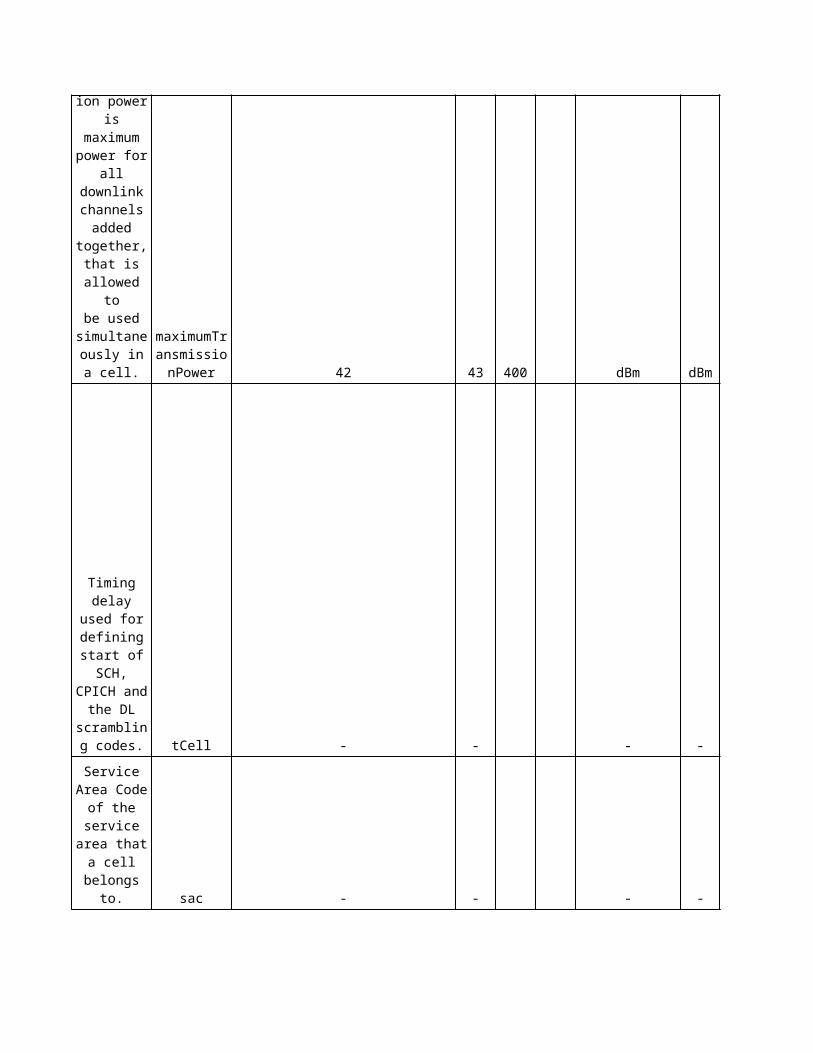
The periodic cell update/URA update timer (MS timer).The CELL UPDATE/URA UPDATE retransmission timer (MS timer).
CELL UPDATE/URA UPDATE retransmission counter (MS counter).
NA
The timer for transition to idle mode, when the timer T305 has expired, and the MS detects an "out of service area" (MS timer).
This is the transmission power of the primary common pilot channel. The P-CPICH physical channel carries the common pilots of the cell, which is defined in the cell setup. The transmission power of the CPICH physical channel defines the actual cell size, which means that the power is determined by radio network planning. This parameter is used, for example, for neighbour measurements - critical for the network performance. The default value is 5-10% of the maximum transmitting power of WCDMA BTS, which can be, for example, 43 dBm/carrier. Note: Changing the parameter value will start the cell shutdown procedure in the BTS. Note: The cell is blocked if the WCDMA BTS does not support the used value. Typical supported range is (Cell max power - 18dB)..(Cell max power - 3dB). Value of this parameter is producing the value of the IE Primary CPICH TX power, which is a part of the System Information Block 5. Especially, if the value of the management parameter "MHA used" is set to the value 'Offset used', then the value of the IE Primary CPICH TX power is set equal - in the range of the IE - to the value of this parameter "Transmission power of the CPICH channel" subtracted with the value of the management parameter "Cable Loss".
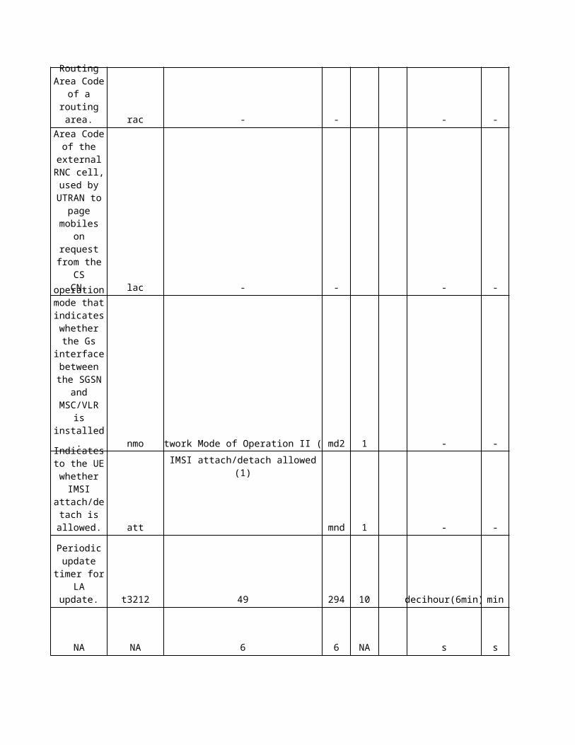
This is the transmission power of the primary CCPCH relative to the CPICH transmission power. The P-CCPCH is a fixed rate (15 ksps, SF = 256) downlink physical channel used to carry the BCH. It is a pure data channel and characterized by a fixed channelisation code (Cch,256,1). The P-CCPCH is broadcast over the entire cell and it is not transmitted during the first 256 chips of each slot, where Primary SCH and Secondary SCH are transmitted. Note: Changing the parameter value will start the cell shutdown procedure in the BTS.
This is the transmission power of the primary synchronisation channel. The power level is relative to the [FDD-primary CPICH power]. The primary SCH consists of a modulated code 256 chips in length: the Primary Synchronisation Code (PSC) transmitted once every slot. The PSC is the same for every cell in the system, and it enables the downlink slot synchronisation in the cell. Note: Changing the parameter value will start the cell shutdown procedure in the BTS.
This is the transmission power of the secondary synchronisation channel related to the Primary CPICH transmission power. The secondary SCH consists of repeatedly transmitting a length 15 sequence of modulated codes 256 chips in length. These are the Secondary Synchronisation Codes (SSC), transmitted in parallel with the primary SCH. This sequence on the secondary SCH enables the downlink frame synchronisation, and indicates, to which code group the cell downlink scrambling code belongs. Each SSC is chosen from a set of 16 different codes 256 chips in length. Note: Changing the parameter value will start the cell shutdown procedure in the BTS.
This is the transmission power of one Aquisition Indicator (AI) compared to CPICH power. If a WCDMA BTS transmits a large number of AIs, then the total power of AICH increases. The AICH consists of a repeated sequence of 15 consecutive Access Slots (AS), each one 5120 chips in length. Each access slot consists of two parts: an Acquisition Indicator (AI) part consisting of 32 real-valued symbols, and a second part, 1024 chips in length, which has no transmission and is not formally part of the AICH. This second part of the slot is reserved for possible use by CSICH, or possible future use by other physical channels. The spreading factor (SF) used for the channelisation of the AICH is 256, and the phase reference for the AICH is the P-CPICH.
This is the transmission power of the S-CCPCH channel, which carries: - a PCH (containing PCCH), a FACH (containing DCCH/BCCH/CCCH) and a FACH (containing DTCH). Or alternatively (when standalone PCH is mapped to an another S-CCPCH) carries: - a FACH (containing DCCH/BCCH/CCCH) and a FACH (containing DTCH). In both cases the spreading factor of this S-CCPCH is 64 (60 ksps) and proposed default value is 0 dB. The transmission power value is relative to the CPICH transmission power.
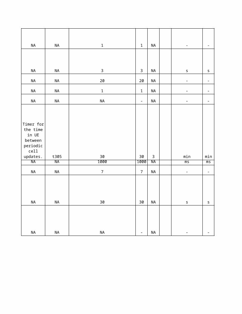
NA
NA
The RRC CONNECTION REQUEST retransmission timer (MS timer).
RRC CONNECTION REQUEST retransmission counter (MS counter).
This is the transmission power of the PICH channel. It carries the paging indicators which tell the UE to read the paging message from the associated secondary CCPCH. The transmission power value is relative to the CPICH transmission power. It may depend on the number of paging indicators (PI) per frame. The following table shows the recommended values for the different cases N. PI per frame (NP), Repetition of PICH bits, Power relative to CPICH (dB): 18, 16, -10 36, 8, -10 72, 4, -8 144, 2, -5
The DRX cycle length used by UTRAN to count paging occasions for discontinuous reception. (The duration of the DRX cycle is 2 <power> k frames, where 'k' is the used DRX cycle length coefficient for UTRAN.)
This timer is started when the UE detects an "out of service area" in URA_PCH or CELL_PCH state. This timer is stopped when the UE detects an "in service area". When the timer expires the UE initiates cell update procedure (MS timer).
This timer is started when the T316 expires and the UE detects an "out of service area". This timer is stopped when the UE detects an "in service area". When the timer expires the UE transits to idle mode (MS timer).
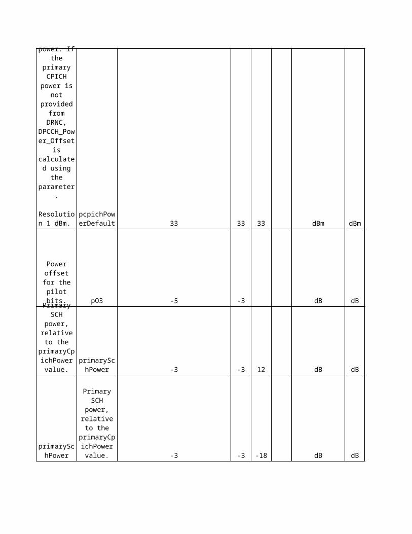
The RRC connection re-establishment timer for AM bearers (UE timer).
NA
NA
NA
The UE CAPABILITY INFORMATION retransmission timer (MS timer).UE CAPABILITY INFORMATION retransmission counter (MS counter).The RRC CONNECTION RELEASE COMPLETE retransmission timer.
NA
The timer for supervising successful connection establishment in case of an inter-RAT cell re-selection (MS timer).
Started when the criteria for radio link failure are fulfilled and stopped when the Cell Update procedure has been completed.
The service area code used in the service area (cell) broadcast. The area where the Service Area Broadcast messages are transmitted. SACB is defined for each cell independently from the "location reporting area" (SAC). SACB ties a cell to a certain service area from the Service Area Broadcast (or Cell broadcast Center) service point of view. A cell belongs to a certain Broadcast Service Area.
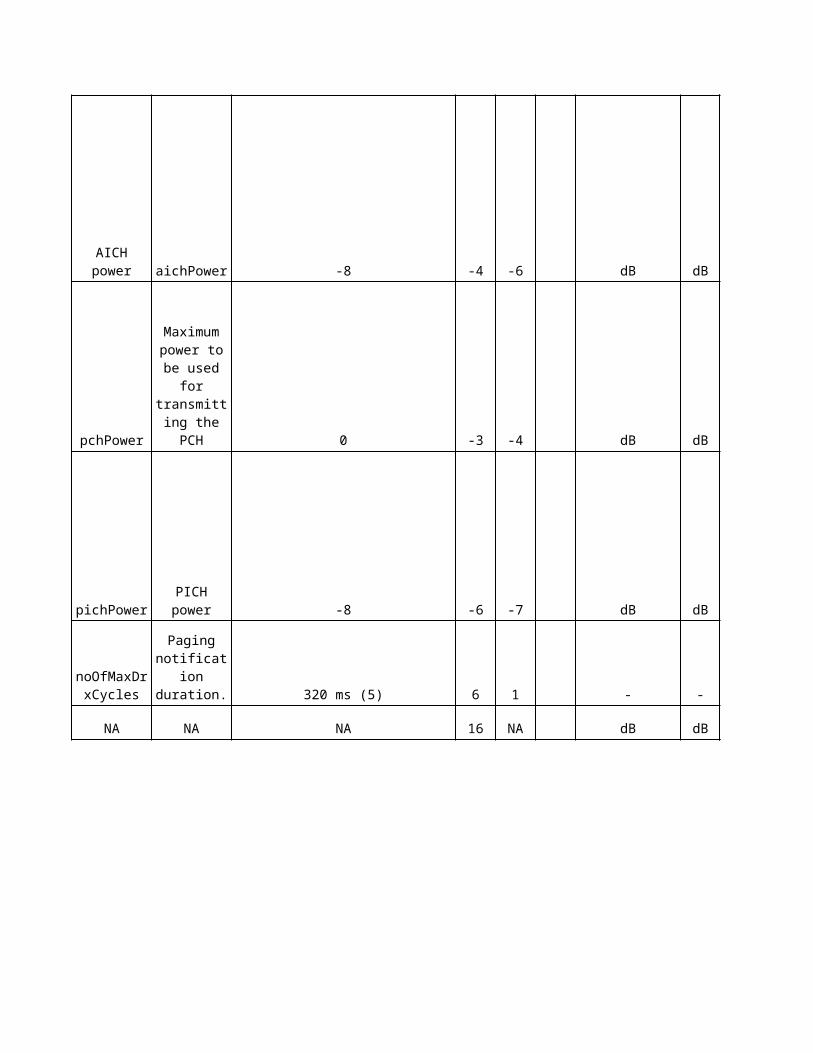
Sie
me
ns
De
sc
rip
tio
n
UTRA Absolute Radio Frequency Channel Number. A channel number corresponds to 5 MHz bandwidth. Its location in the frequency band is defined with a granularity of 200 KHz.
Maximum power for all downlink channels added together, that is allowed to be used in a cell
Maximum power for all downlink channels added together, that is allowed to be used in a cell
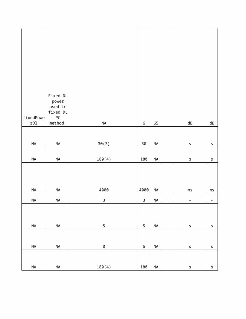
Routing Area Code
Location Area Code
Timing delay used for defining start of SCH, CPICH and the DL scrambling code in a cell.
Service Area Code The SAC identifies an area to the CN. A unique relationship between UtranCell and Service Area is required.
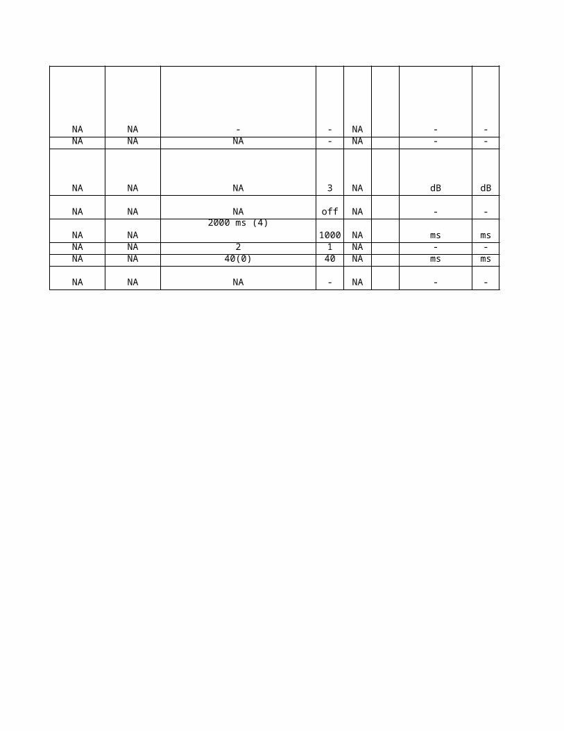
Attach-Detach
T3212
Network operation mode is used to indicate whether the Gs interface is installed or not.
Timer started in UE on establishment of dedicated channel. Timer stopped in UE, if N312 consecutive ‘SYNC_IND’ have been received from UE RRC.
Number of consecutive ‘SYNC_IND’ neccesary in order to declare the successful establishment of a dedicated channel
Radio Link Timeout: Within T313 N315 ‘IN_SYNC_IND’ are expected to be received within the UE. Otherwise a Radio Link Failure is to be detected
Number of ‘OUT_OF_SYNC_IND’ that trigger start of T313
Number of successive ‘SYNC_IND’ to be received during T313.
Identifies the UTRAN Registration Area (URA) of the cell.
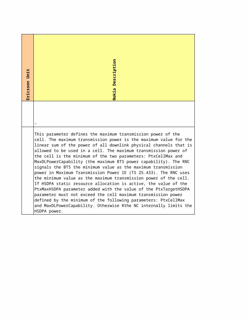
Supervision of Cell Update procedure Unit
Define the time period between updating a CELL or an URA
Number of allowed retransmitions of a CELL UPDATE REQUEST message
Started when the timer T305 has expired and the UE detects "out “f service area" and stopped when the UE detects "in service area". etermines the time a UE is allowed to search for a suitable cell while a Cell Update is pending.
The DL scrambling code of the CPICH identifies a cell uniquely if the code is always allocated with sufficient reuse distancesOn modification the duplication of the P-CPICH scrambling code is prohibited
Indicates the total transmitted power offset of the CPICH Power (this information is needed, if the UE is required to measure the DL pathloss)
Indicates the difference of the BCH power to the Primary CPICH Tx power
Indicates the difference of the Primary SCH power to the Primary CPICH Tx power
Indicates the difference of the Primary SCH power to the Primary CPICH Tx power
Indicates the difference of the AICH power to the Primary CPICH Tx power.
Indicates the difference of the PCH power to the Primary CPICH Tx power
Indicates the difference of the PICH power to the Primary CPICH Tx power
Needed if idle DRX period could not be ‘re-used’
Power offset for evaluation of max. Transmission power
Cell specific max DL transmission power (relative to CPICH power)
Started when the UE detects "out of service area" in URA_PCH or CELL_PCH state, stopped when the UE detects "in service area".
Started when the T316 expires and the UE detects "out of service area", stopped when the UE detects"in service area".
Timer started in UE at transmission of RRC CONNECTION REQ and stopped after the reception of RRC CONNECTION SETUP.Recommendation: Replace Default by optimized value
Max. Number of repetitions of RRC CONNECTION REQ;
PLMN Value Tag
T304N304T308
Started upon reselection of a cell belonging to another radio access system from connected mode. Stopped after successful establishment of a connection in the new cell.
Started when the criteria for radio link failure are fulfilled and stopped when the Cell Update procedure has been completed.
Started when the criteria for radio link failure are fulfilled and stopped when the Cell Update procedure has been completed
Service Area Code to be used for Cell Broadcast domain
Power offset relative to the maximum DPCCH DL Tx power and threshold A. This parameter shall be set to same value for all cells within the same Node B.
Suppression of alarm messages for cell/Common transport channels
Secondary Scrambling Code,0 means secondary scrambling code isn’t used
Eri
cs
so
n D
es
cri
pti
on
-
Maximum transmission power is maximum power for all downlink channels added together, that is allowed to be used simultaneously in a cell.
Old name: maxTxPowerDl
Unit: 0.1 dBResolution: 1
0 : 0dBm1 : 0.1dBm......
500 : 50dBm
Maximum transmission power is maximum power for all downlink channels added together, that is allowed to be used simultaneously in a cell.
Old name: maxTxPowerDl
Unit: 0.1 dBResolution: 1
0 : 0dBm1 : 0.1dBm......
500 : 50dBm
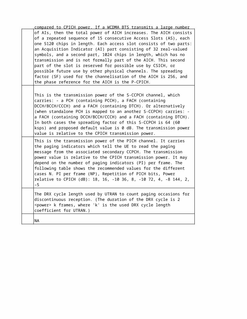
Timing delay used for defining start of SCH, CPICH and the DL scrambling codes.0: 0 chip1: 256 chip..9: 2304 chipChanging this attribute may affect traffic.
A ServiceArea is used by UTRAN to indicate the location of a Ue to the CN. It is also used by the CN toindicate to UTRAN in which area to broadcast CN information. It is unique in the LA. An LA can span overseveral RNCs.Changing this parameter can cause a mismatch between CN configuration and UTRAN configuration until ithas been configured in both places.Old name: sAC
Routing Area Code of a routing area. An RA is used by UTRAN to page mobiles on request from the PS CN.When the parameter is changed, UTRAN shall update system information and notity UEs.Old name: rAC
The Location Area Code of the external RNC cell, used by UTRAN to page mobiles on request from the CSCN.Old name: lAC
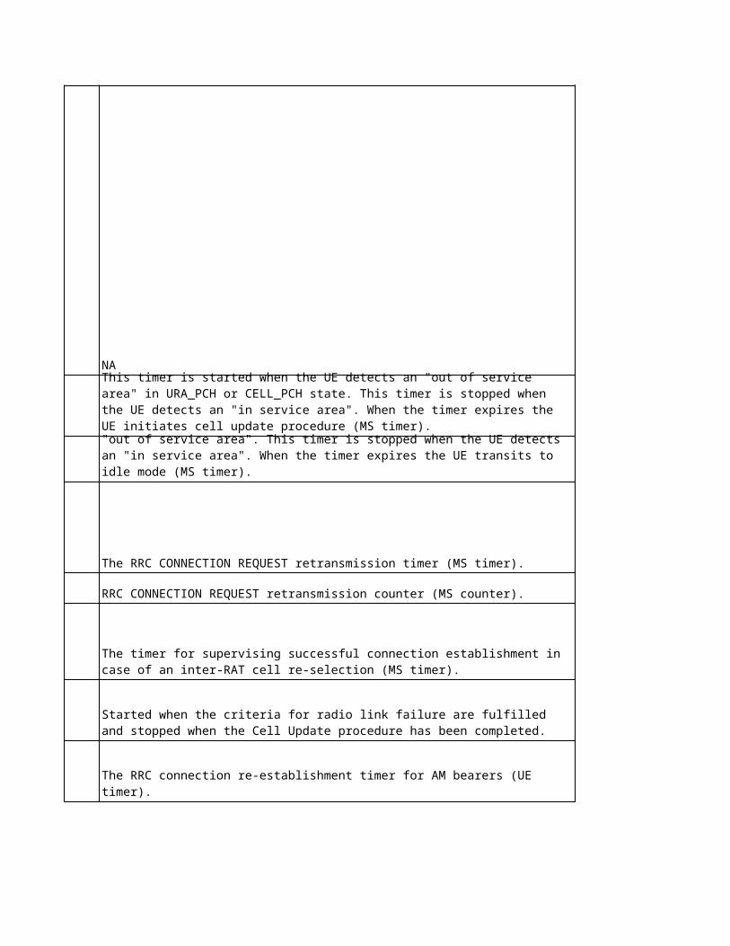
NA
NA
NA
NA
NA
NA
Default = MODE_II = 1Network operation mode that indicates whether the Gs interface between the SGSN and MSC/VLR is installed.
Indicates to the UE whether IMSI attach/detach is allowed. (Some IMSIs are not allowed in some LAs.) This helps to facilitate the avoidance of unnecessary paging attempts. The value is sent on the BCCH.
FALSE: IMSI attach not allowedTRUE: IMSI attach allowed
Periodic update timer for LA update.
Unit: 0.1 hours (= 1 decihour = 6 minutes = 360 seconds)Resolution: 1
0 means infinite time, i.e. not active.
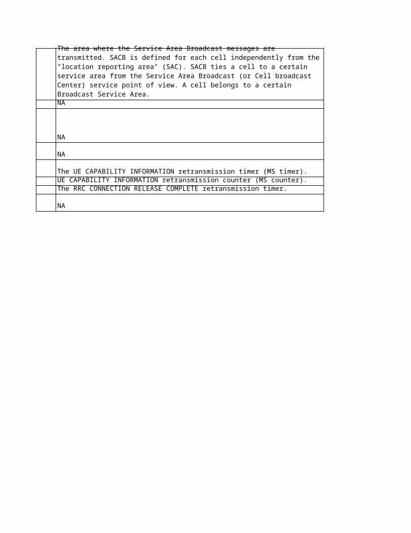
NA
NA
NA
NA
Timer for the time in UE between periodic cell updates. If timer has expired, the UE sends a new CELL UPDATE.
0: No updating1: 5 min2: 103: 304: 605: 1206: 3607: 720 min
Default primary CPICH power. If the primary CPICH power is not provided from DRNC, DPCCH_Power_Offset is calculated using the parameter.
Resolution 1 dBm.
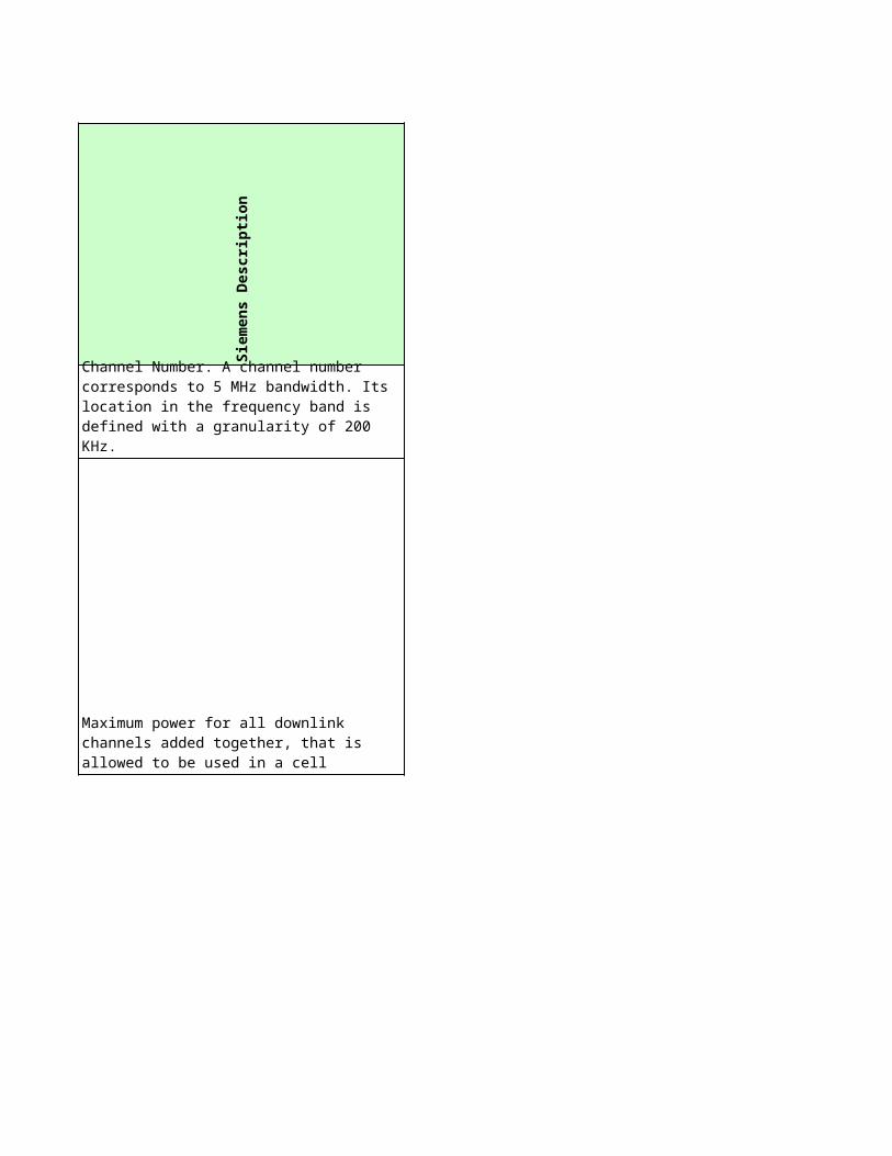
Power offset for the pilot bits.
Unit: 0.25 dBResolution: 1
0: 0.00 dB 1: 0.25 dB...24: 6.00 dB
Primary SCH power, relative to the primaryCpichPower value.
-350: -35.0 dB-349: -34.9 dB.. 150: 15.0 dB
Old name: schPower1
AICH power, to be used for transmitting on AICH, relative to the primaryCpichPower value.
The value range is set in a short term to cover both the RRC and NBAP spec.
Unit: 1 dBResolution: 1
Maximum power to be used for transmitting the PCH, relative to the primaryCpichPower value.
Unit: 0.1 dBResolution: 1
-350: -35.0 dB-349: -34.9 dB.. 150: 15.0 dB
NA
NA
NA
NA
NA
PICH power is the power to be used for transmitting on the physical channel carrying the paging indicators, relative to the primaryCpichPower value.
Unit: 1 dBResolution: 1
-10: -10 dB- 9: -9 dB.. 5: 5 dB
Paging notification duration.
To notify UEs in IDLE mode about a system information update, the RNC sends a paging message on the PCH at every page occasion of a number of maximum DRX cycles.
Fixed DL power used in fixed DL PC method. The power value is expressed relative to the PCPICH power.
Resolution 1 (=0.5 dB).
1 : -35dB2 : -34.5dB3 : -34dB4 : -33.5dB5 : -33dB6 : -32.5dB.......65: -3dB.......70: - 0.5dB71: 0dB72: 0.5dB.......101 : 15dB
NA
NA
NA
NANA
NA
NA
NANANA
NA
No
kia
Ob
jec
t
No
kia
Lo
ng
Na
me
No
kia
na
me
Sie
me
ns
Ob
jec
t
WCEL HS-PDSCH code set HSPDSCHCodeSet hsdpa
WCEL HSDPA enabled HSDPAenabled hsdpa
WCELMaximum number of HS-SCCH codesMaxNbrOfHSSCCHCodes hsdpa
NA NA NA hsdpa
NA NA NA hsrrm
NA NA NA hsrrm
NA NA NA hsrrm
NA NA NA hsrrm
NA NA NA hsrrm
NA NA NA NA
NA NA NA hsrrm
NA NA NA NA
NA NA NA hsrrm
NA NA NA hsrrm
-Serving HS-DSCH cell change and SHO on/off switchHSDPAMobility -
WCEL mrd_sys3
WCEL DirectedRRCEnabled mrd_sys3
RNC mrd_sys3
WCEL Sector Identifier SectorID mrd_sys3
Directed RRC connection setup for
HSDPA layer enabled DirectedRRCForHSDPALa
yerEnabled
Directed RRC connection
setup enabled
DRRC connection setup for
HSDPA layer enhancement
sDirectedRRCForHSDPALa
yerEnhanc
WCEL Prx Offset for DRRC DRRCprxOffset mrd_sys3
WCEL Ptx Offset for DRRC DRRCptxOffset mrd_sys3
WCEL Prx Margin for DRRC DRRCprxMargin mrd_sys3
WCEL Ptx Margin for DRRC DRRCptxMargin mrd_sys3
Sie
me
ns
Lo
ng
Na
me
Sie
me
ns
na
me
Eri
cs
so
n O
bje
ct
Eri
cs
so
n L
on
g N
am
e
Eri
cs
so
n n
am
e
Number of HS-PDSCH codes no_pdsch Hsdsch RNC numHsPdschCodes
Number of HS-PDSCH codes no_pdsch Hsdsch RNC operationalState
Nr of HS-SCCHs no_scch NA NA NA
HS-DSCH Power Offset po_dsch Carrier RBS hsPowerMargin
UE HS-DSCH Physical Layer Category ue_cate Carrier RBS supportOf16qam
CQI Feedback Cycle k cqi_cyclek Hsdsch RNC cqiFeedbackCycle
CQI Repetition Factor cqi_rep Hsdsch RNC initialCqiRepetitionFactor
ACK-NACK Repetition Factor ack_nack_rep Hsdsch RNCinitialAckNackRepetitionFactor
CQI Power Offset cqi_po Hsdsch RNC deltaCqi1
NA NA Hsdsch RNC deltaCqi2
ACK Power Offset ack_po Hsdsch RNC deltaAck1
NA NA Hsdsch RNC deltaAck2
NACK Power Offset nack_po Hsdsch RNC deltaNack1
Hsdsch RNC deltaNack2
HS-SSCH Power Offset hsscch_po Carrier RBS hsScchMaxCodePower
- - RncFunction RNC hsCellChangeAllowed
Ue differentiation data_no1 NA NA NA
Ue differentiation data_no1 NA NA NA
Ue differentiation data_no1 NA NA NA
Ue differentiation data_no1 NA NA NA
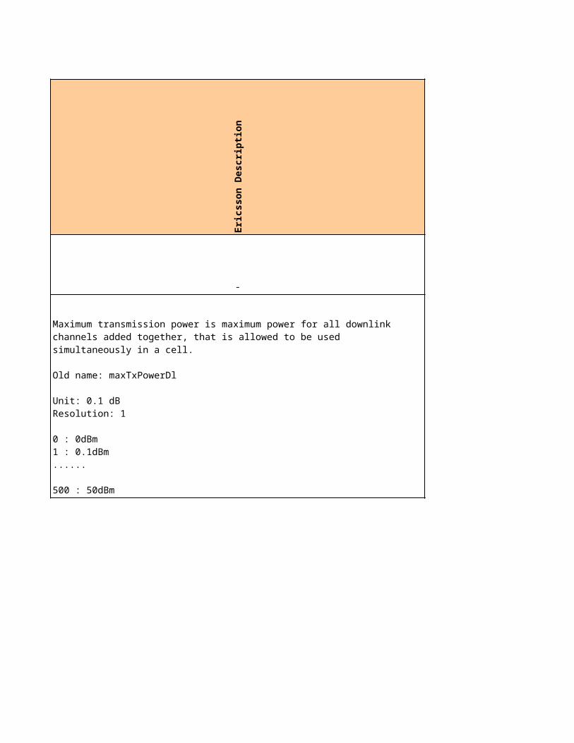
Ue differentiation data_no1 NA NA NA
Ue differentiation data_no1 NA NA NA
Ue differentiation data_no1 NA NA NA
Ue differentiation data_no1 NA NA NA
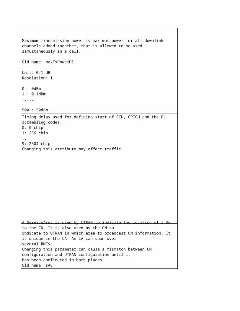
No
kia
pro
po
se
d
Sie
me
ns
cu
rre
nt
Eri
cs
so
n c
urr
en
t
Ag
ree
d
No
kia
Un
it
Sie
me
ns
Un
it
Eri
cs
so
n U
nit
32 5 5 - - -
Enabled(1) 5 ENABLED (1) - - -
3 3 NA - - NA
NA 3 2 dB dB dB
NA 1-12 1 - - -
NA 4 8 ms ms ms
NA 1 1 - - -
NA 1 1 - - -
NA 5 4 - - -
NA NA 6 -
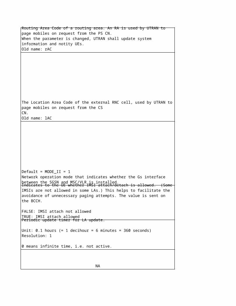
NA 5 5 - - -
NA NA 7 -
NA 5 5 - - -
7 -
NA 3 -20 dB dB 0.1dB
Enabled(1) - TRUE (1) - - NA
0 NA - - NA
0 NA - - NA
Enabled(1) 0 NA - - NA
0 NA - - NA
1 carrier site: Disable(0)2 carriers site: F1,
Enabled(1) and F2, Disable(0)
1 carrier site: Disable(0)2 carriers site:
Enabled(1) for both F1&F2
sector 1=1sector 2=2sector 3=3sector 6=1sector 7=2sector 8=3
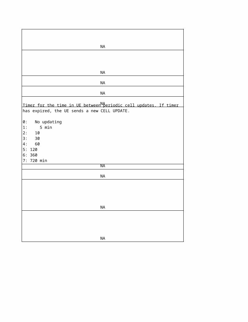
-1 0 NA dB - NA
-3 0 NA dB - NA
0 0 NA dB - NA
-0.5 0 NA dB - NA
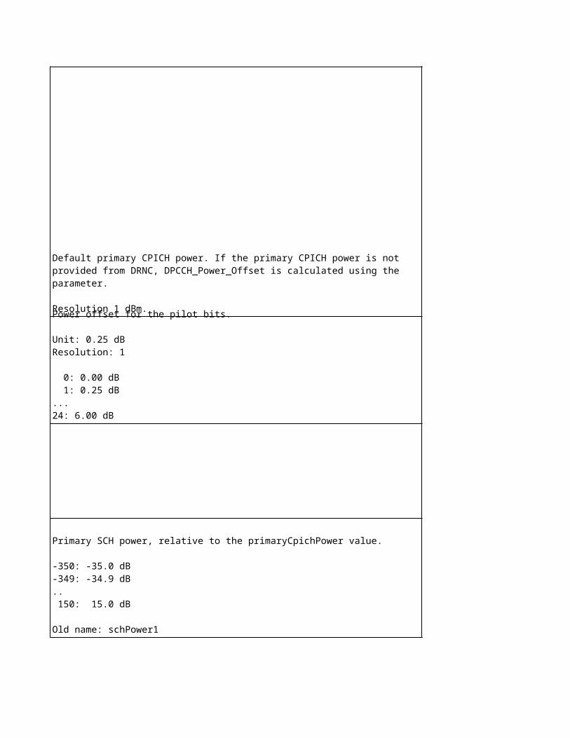
No
kia
De
sc
rip
tio
n
NA
NA
NA
NA
NA
NA
The parameter enables / disables the use of HSDPA in the cell. If the parameter is enabled (1) the system checks that the maximum amount of HSDPA-capable BTSs and cells is not exceeded. If it is not possible to activate HSDPA for a new BTS or cell then the activation does not succeed and error is printed out. The parameter is also used to indicate HSDPA capable network. This information can be sent to the UEs (HSDPA cell indicator) and UE displays it for the end user.
This parameter defines the maximum number of HS-SCCH codes (SF 128) that can be reserved in one cell. More than one HS-SCCH code can be used if the HSDPA code multiplexing functionality is in use. The actual number of reserved codes depends on for example HSDPA capabilities and HSDPA code multiplexing support (RNC and BTS).
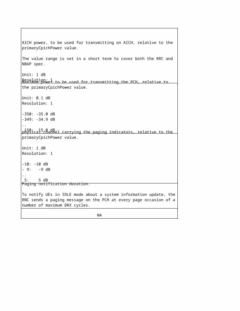
NA
NA
NA
The parameter enables/disables the use of the directed RRC connection setup in the cell.
Parameter enables/disables serving HS-DSCH cell change & SHO of the associated DPCH.If the value is disabled, basic mobility handling with switching to FACH/DCH is utilised. If the value is enabled, SHO of the associated DPCH and serving HS-DSCH cell change are utilised.
Enables / disables the use of the Directed RRC connection setup for the HSDPA layer in the cell.
When this parameter is enabled and the Directed RRC connection setup for HSDPA layer is enabled (DirectedRRCForHSDPALayerEnabled parameter is enabled) in the cell, the following enhancements are in use: 1. The RNC takes into account the service requested in the RRC connection request when making the decision of Directed RRC connection setup to HSDPA layer. The services are defined with the DRRCForHSDPALayerServices parameter. 2. The RNC supports more than 2 layers. 3. The RNC supports HSDPA load sharing between layers. 4. The RNC supports simultaneous use of Directed RRC Connection Setup and Directed RRC Connection Setup for HSDPA layer features (the DirectedRRCEnabled and DirectedRRCForHSDPALayerEnabled parameters are enabled).
This parameter gives a unique identifier to a sector of the base station where the cell belongs to. The RNC uses the sector identifier in order to integrate cells (carrier frequencies) which have equal coverage areas within one base station. A cell does not belong to any particular sector when the value of the sector indentifier is zero.
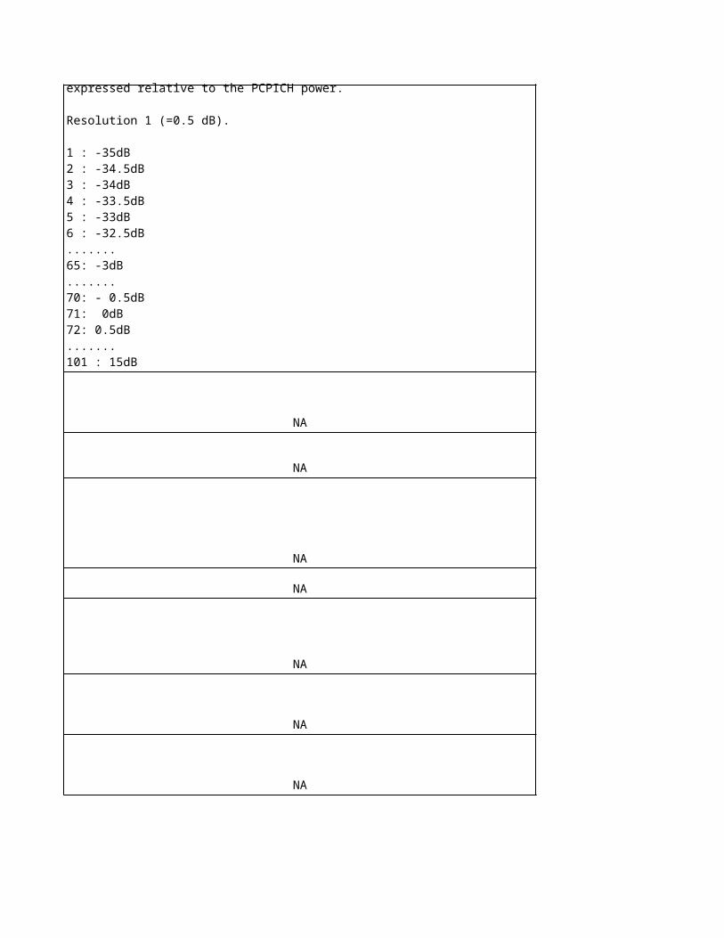
This parameter determines the threshold level which the uplink load of the source cell must exceed before the Admission control of the RNC may direct the RRC connection setup to another cell within the sector. The Admission control calculates the threshold level by adding the value of the parameter to the target value of the total received power (PrxTarget).
This parameter determines the threshold level which the downlink load of the source cell must exceed before the Admission control of the RNC may direct the RRC connection setup to another cell within the sector. The Admission control calculates the threshold level by adding the value of the parameter to the target value of the total transmitted power (PtxTarget).
This parameter determines the threshold level which the uplink load of the cell may not exceed in order for the Directed RRC Connection Setup to be possible from another cell (source cell) of the same sector. The Admission control of the RNC calculates the threshold level by adding the value of the parameter to the total received power level of the source cell.
This parameter determines the threshold level which the downlink load of the cell may not exceed in order for the Directed RRC Connection Setup to be possible from another cell (source cell) of the same sector. The Admission control of the RNC calculates the threshold level by adding the value of the parameter to the total transmitted power level of the source cell.
Sie
me
ns
De
sc
rip
tio
n
UE category for HSDPA, part of UE capabilities. Valid values are 1 – 12
Period of repetition of a CQI measurement reports
Number of repetitions of ACK/NACK reports
Number of HS-PDSCH codes per cell. The number of HS-PDSCH codes of all cells under a Node B must be the same value.If HS-PDSCH = 15 and PCH is mapped on standalone PCCH, then Nr of HS-SCCHs <= 3.
Number of HS-PDSCH codes per cell. The number of HS-PDSCH codes of all cells under a Node B must be the same value.If HS-PDSCH = 15 and PCH is mapped on standalone PCCH, then Nr of HS-SCCHs <= 3.
Number of HS-SCCH channels; If ccho_type of dlcc command is 0 or 1 (not "S-CCPCH carrying PCH/FACH_multiplexing") and "no_pdsch=15", "no_scch=4" is cannot be specified.
Default Power offset between HS-PDSCH and P-CPICH/S-CPICH.Note: this must be set to the same value for all cells within one Node B
Number of repetitions of a CQI report. Not necessary in case CQI Feedback Cycle k = 0
Power offset used in the UL between the HS-DPCCH slots carrying CQI information and the associated DPCCH 5 (corresponds to 0dB relative to DPCCH)
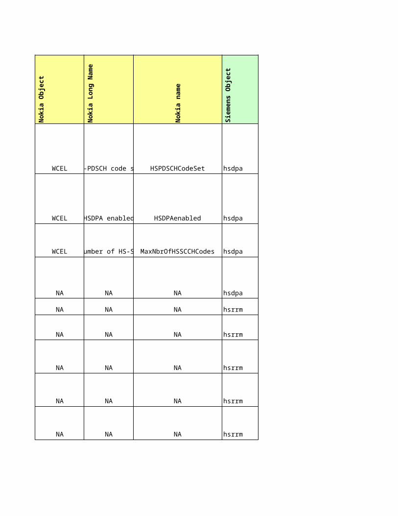
Power offset of HS-SCCH relative to the pilot bits on the DL DPCCH
-
Ue differentiation
Ue differentiation
Ue differentiation
Ue differentiation
Power offset used in the UL between the HS-DPCCH slot carrying HARQ ACK information and the associated DPCCH
Power offset used in the UL between the HS-DPCCH slot carrying HARQ NACK information and the associated DPCCH
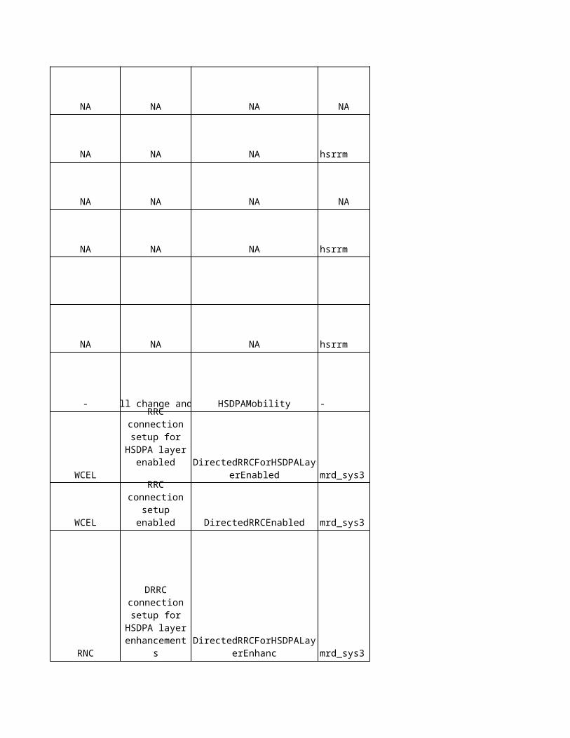
Ue differentiation
Ue differentiation
Ue differentiation
Ue differentiation
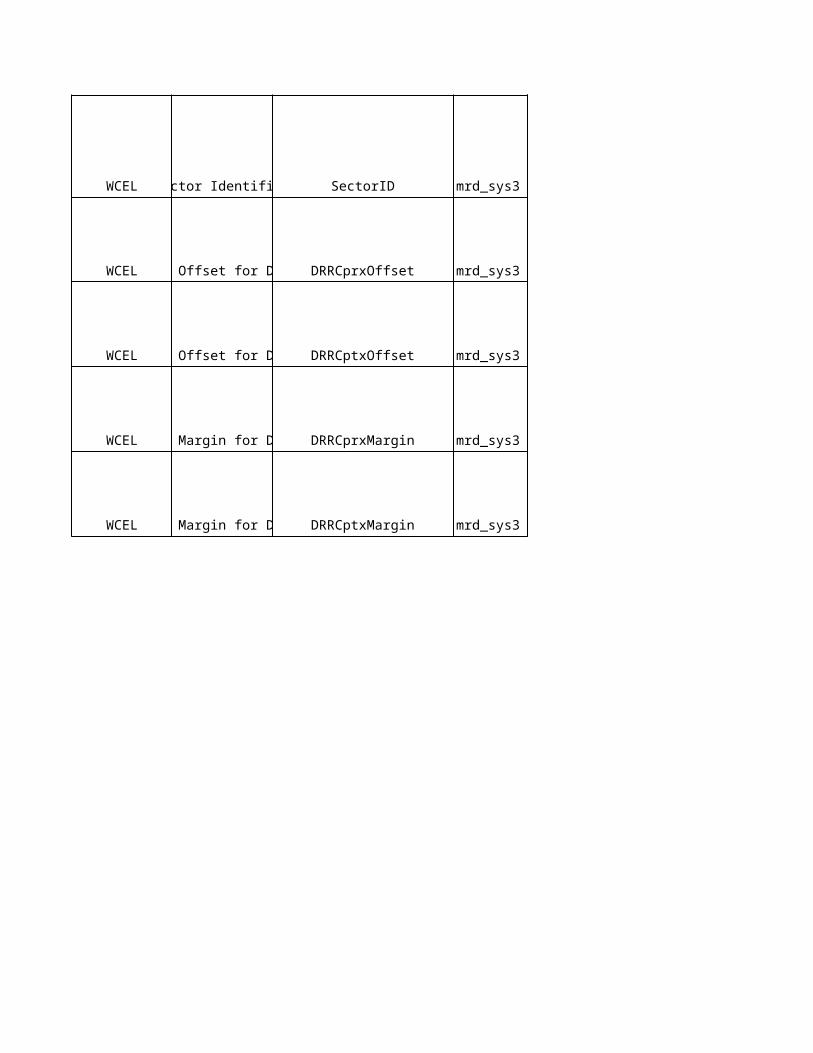
Eri
cs
so
n D
es
cri
pti
on
The operational state of the HSDPA resources in the cell.
NA
Number of codes of SF=16 used for the HS-PDSCH.When the number of codes is increased, all traffic is released from the cell.When the number is decreased, traffic is not released in the cell, but the Hs-dsch throughput may be affected.Unit: 1 codeRes
The power margin the HSDPA scheduling is using when allocating the remaining power of the cell carrier. The margin is relative the maximum available power (Maximum Transmission Power) of the RbsLocalCell.UNIT=0.1(dB)
This parameter controls the 16QAM support in the cell. If set to TRUE, the capability of the UE decides whether 16QAM or QPSK is used.
The duration of the CQI feedback cycle on HS-DPCCH.Unit: 1 msResolution: N/A
The initial number of repetitions for CQI report messages on HS-DPCCH.Must be set less than or equal to cqiFeedbackCycle / 2ms.Unit: N/AResolution: 1
The initial number of repetitions for ACK/NACK feedback transmissions on HS-DPCCH.Unit: N/AResolution: 1
The power offset for CQI report messages on HS-DPCCH for UE Connections using one RLS.Unit: N/AResolution: 1
The power offset for CQI report messages on HS-DPCCH for UE Connections using two or more RLSs.Unit: N/AResolution: 1
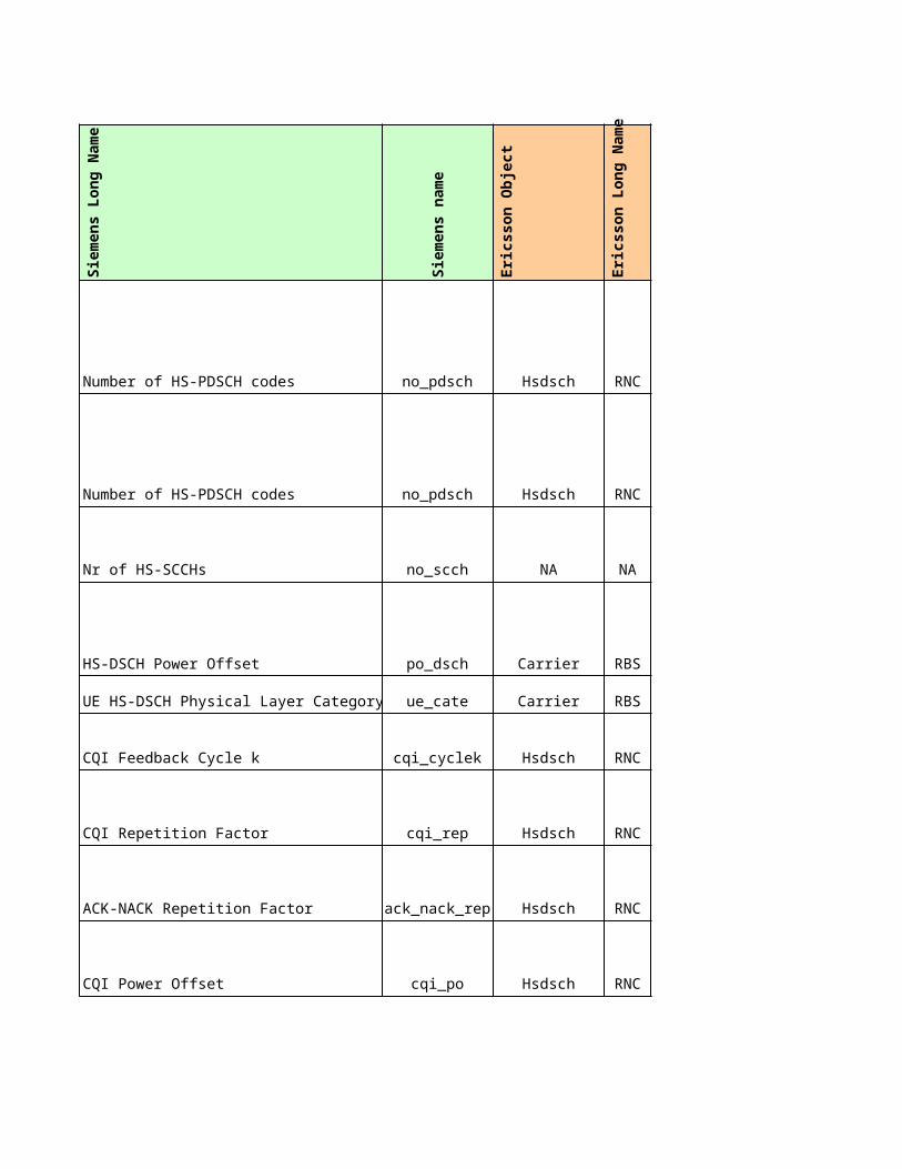
NA
NA
NA
NA
The power offset for acknowledgement messages on HS-DPCCH for UE Connections using one RLS.Unit: N/AResolution: 1
The power offset for acknowledgement messages on HS-DPCCH for UE Connections using two or more RLSs.Unit: N/AResolution: 1
The power offset for non-acknowledgement messages on HS-DPCCH for UE Connections using one RLS.Unit: N/AResolution: 1
The power offset for non-acknowledgement messages on HS-DPCCH for UE Connections using two or more RLSs.Unit: N/AResolution: 1
HS-SCCH maximum code power relative PCPICH reference power. This parameter also determines the fixed power level for HS-SCCH. UNIT=0.1(dB)RESOLUTION=5
Overall On/Off switch for serving HS-DSCH cell changeUnit: N/AResolution: N/A
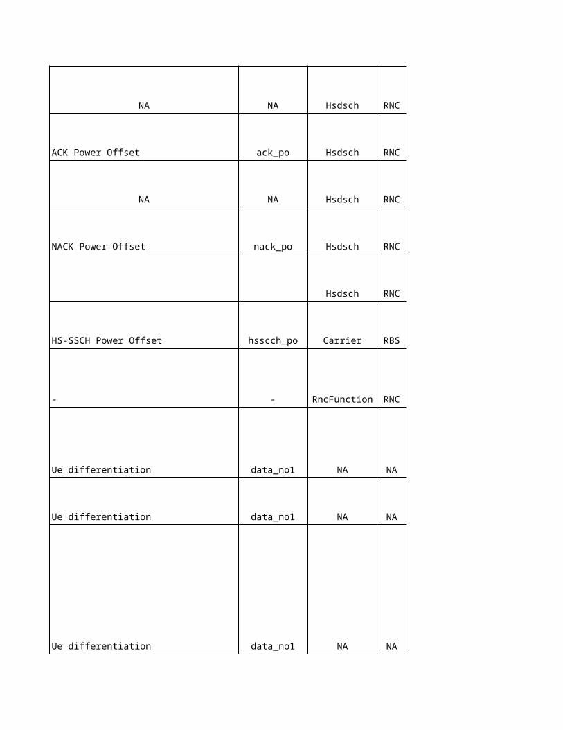
NA
NA
NA
NA
Intra Frequency Handover
No
kia
Ob
jec
t
No
kia
Lo
ng
Na
me
No
kia
na
me
Sie
me
ns
Ob
jec
t
NA NA NA ifmrms
NA NA NA ifmrms
FMCSMaximum Active Set Size MaxActiveSetSize ifmrms
NA NA NA cell iub
ADJS CPICH Ec/No Offset AdjsEcNoOffset aci
RNC IurUPSupport -
HOPSEnable Inter-RNC Soft HandoverEnableInterRNCsho
-
User Plane support of Iur connection
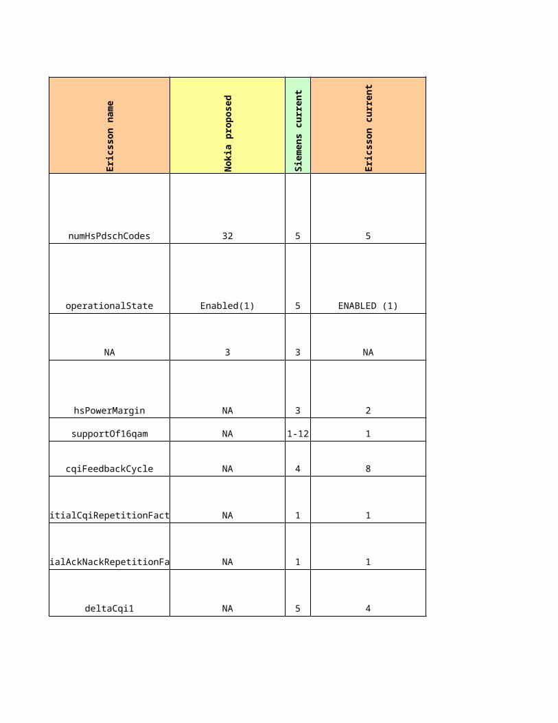
ADJIInclude in System Information AdjiSIB aci
ADJSInclude in System Information AdjiSIB aciFor Event 1A
FMCS Addition Window AdditionWindow ifmrms
NA NA NA ifmrms
FMCSActive Set Weighting CoefficientActiveSetWeightingCoefficient ifmrms
NA NA NA ifmrms
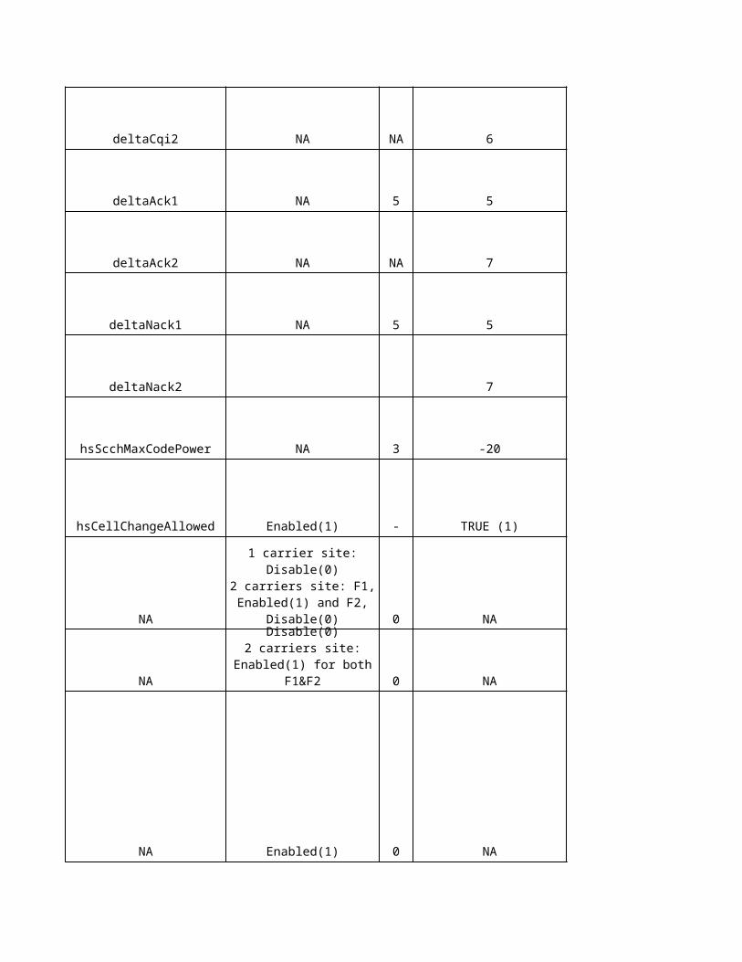
FMCS Addition Time AdditionTime ifmrmsNA NA NA ifmrms
FMCSAddition Reporting Interval AdditionReportingInterval ifmrmsFor Event 1B
FMCS Drop Window DropWindow ifmrms
FMCSActive Set Weighting CoefficientActiveSetWeightingCoefficient ifmrms
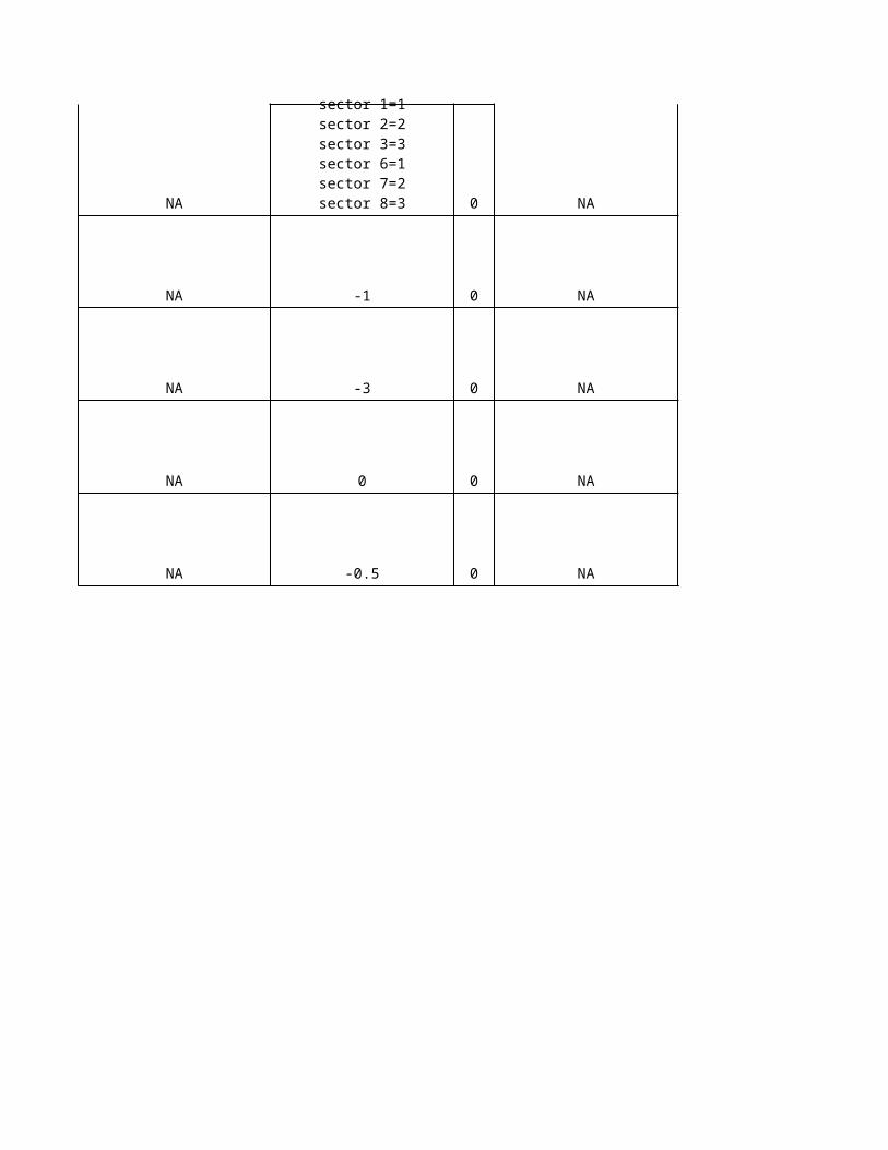
NA NA NA ifmrms
FMCS Drop Time DropTime ifmrmsFor Event 1C
FMCS Replacement Window ReplacementWindow ifmrms
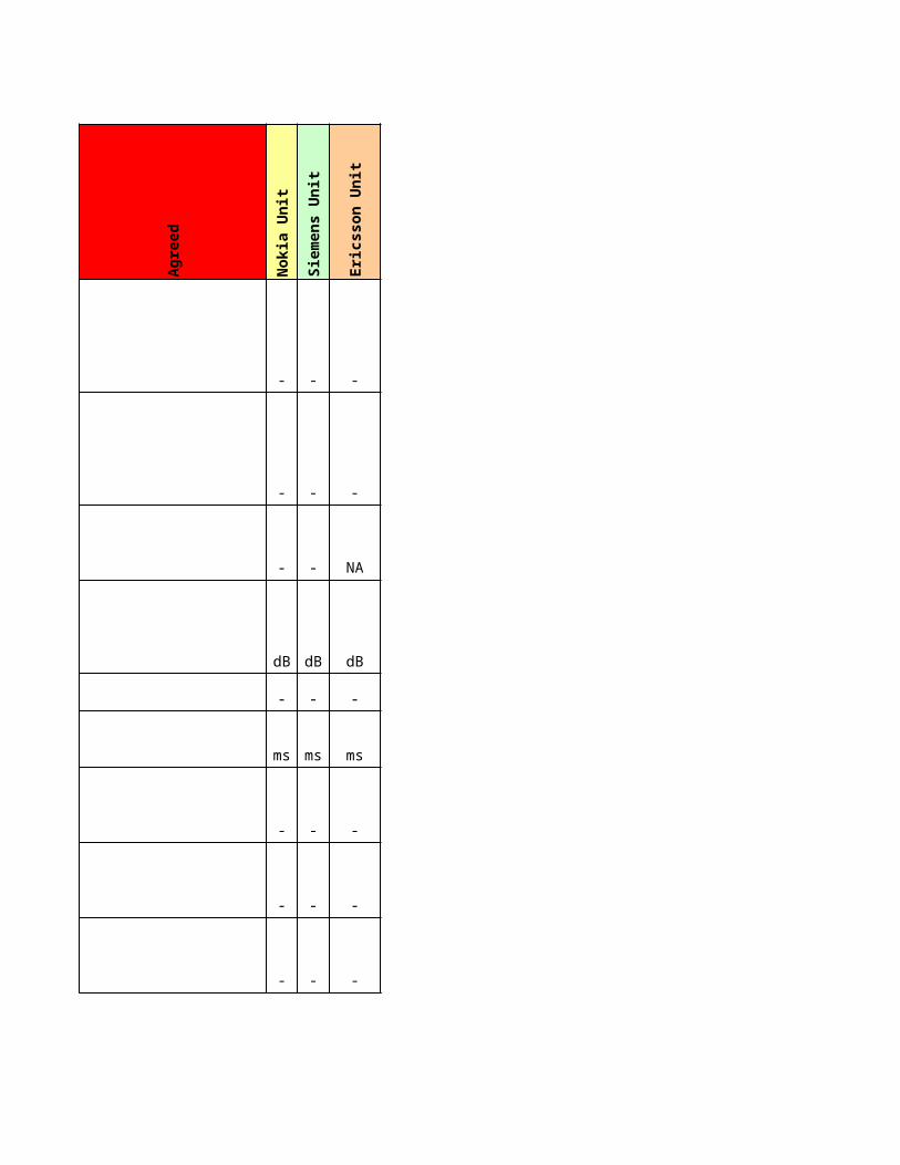
FMCS Replacement Time ReplacementTime ifmrmsNA NA NA ifmrms
FMCSReplacement Reporting IntervalReplacementReportingInterval ifmrms
RNCCPICH Ec/No window for serving HS-DSCH cell selectionHSDPAServCellWindow ifmrms
NA NA NA NA
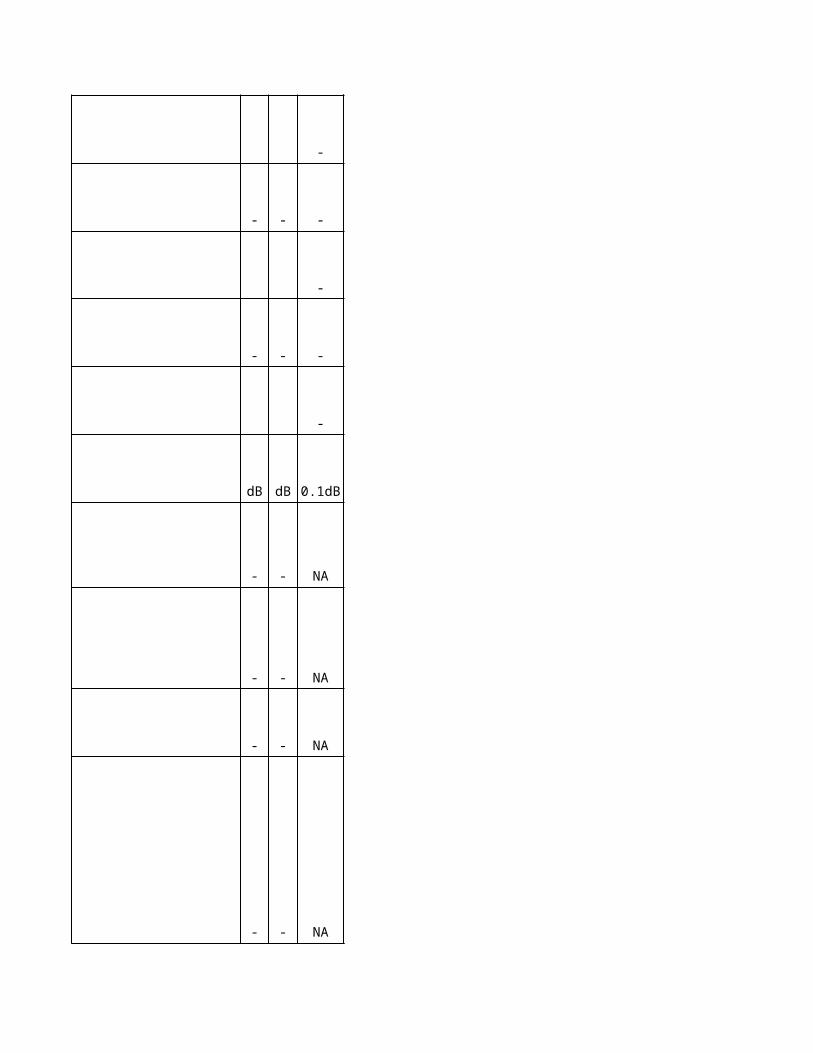
NA NA NA ifmrms
NA NA NA NA
Inter Frequency Handover
No
kia
Ob
jec
t
No
kia
na
me
Sie
me
ns
Ob
jec
t
NA NA NA ifhc
NA NA NA ifhcFor Event 2A
NA NA NA ifhc
NA NA NA ifhc
NA NA NA ifhc
NA NA NA ifhcFor Event 2AD
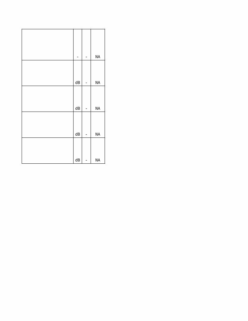
NA NA NA ifhcNA NA NA ifhc
NA NA NA ifhcNA NA NA ifhc
For Event 2B
NA NA NA ifhc
NA NA NA NA
NA NA NA ifhc
NA NA NA ifhc
NA NA NA ifhc
NA NA NA ifhc
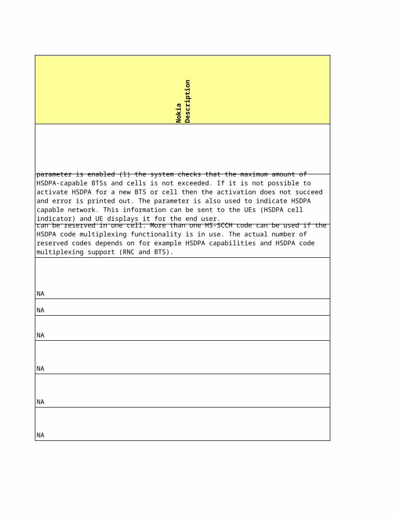
NA NA NA NA
NA NA NA ifhcFor Event 2D
NA NA NA ifhc
NA NA NA NA
NA NA NA NA
NA NA NA NA
NA NA NA ifhc
NA NA NA ifhc
NA NA NA ifhc
NA NA NA NAFor Event 2F
NA NA NA ifhc
NA NA NA NA
NA NA NA ifhc
NA NA NA ifhc
NA NA NA ifhc
NA NA NA NA
FMCIIFHO caused by CPICH Ec/NoIFHOcauseCPICHEcNo -
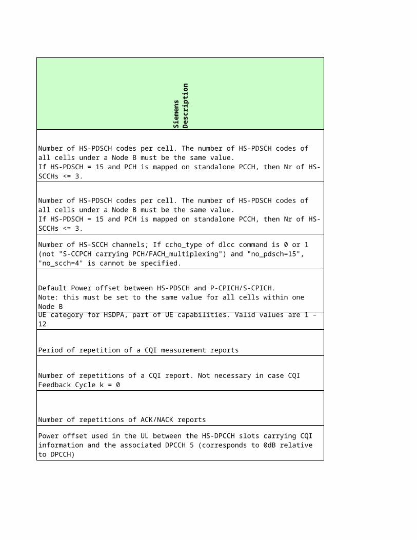
FMCIIFHO caused by CPICH RSCP IFHOcauseCPICHrscp -
FMCSCPICH Ec/No HHO Cancellation HHoEcNoCancel -
FMCSCPICH Ec/No HHO Cancellation TimeHHoEcNoCancelTime -
FMCSCPICH Ec/No HHO Threshold HHoEcNoThreshold -
FMCSCPICH Ec/No HHO Time HysteresisHHoEcNoTimeHysteresis -
FMCSCPICH RSCP HHO Cancellation HHoRscpCancel -
FMCSCPICH RSCP HHO Cancellation TimeHHoRscpCancelTime -
FMCSCPICH RSCP HHO Threshold HHoRscpThreshold -
FMCSCPICH RSCP HHO Time HysteresisHHoRscpTimeHysteresis -
ADJIMinimum CPICH RSCP for IFHO AdjiMinRSCP -
ADJIMaximum UE TX Power on DPCH AdjiTxPwrDPCH -
ADJICPICH Ec/No Margin for IFHO AdjiEcNoMargin -
ADJIMinimum CPICH Ec/No for IFHO AdjiMinEcNo -
ADJIPathloss Margin for IFHO AdjiPlossMargin -
Inter System Handover
No
kia
Ob
jec
t
No
kia
na
me
Sie
me
ns
Ob
jec
t
NA NA NA ishc
NA NA NA ishc
NA NA NA ishcNA NA NA ishcNA NA NA ishc
NA NA NA ishc
NA NA NA ishcNA NA NA ishcNA NA NA ishc
NA NA NA ishc
NA NA NA ishc
NA NA NA ishcNA NA NA ishc
NA NA NA ishc
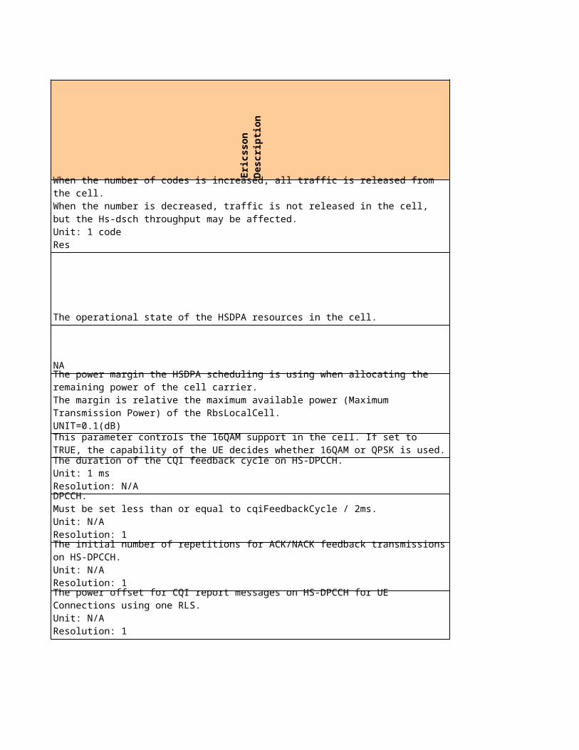
NA NA NA NA
NA NA NA ishc
NA NA NA ishcNA NA NA egc
RNCHandover of NRT PS Service to GSMGsmHandoverNrtPS ishcFMCGGSM HO caused by CPICH Ec/NoGSMcauseCPICHEcNo ishcFMCGGSM HO caused by CPICH RSCPGSMcauseCPICHrscp ishc
NA NA NA agci
ADJGInclude in System Information AdjiSIB agci
HOPGCell Re-selection Minimum RX Level AdjgQrxlevMin egc
HOPGCell Re-selection Quality Offset 1 AdjgQoffset1 agci
HOPGMinimum RX Level for Coverage HOAdjgRxLevMinHO ishc
HOPGMinimum RX Level for Coverage HOAdjgRxLevMinHO ishc
ADJG Band Indicator AdjgBandIndicator egc
ADJGMaximum UE TX Power on TCH AdjgTxPwrMaxTCH NA
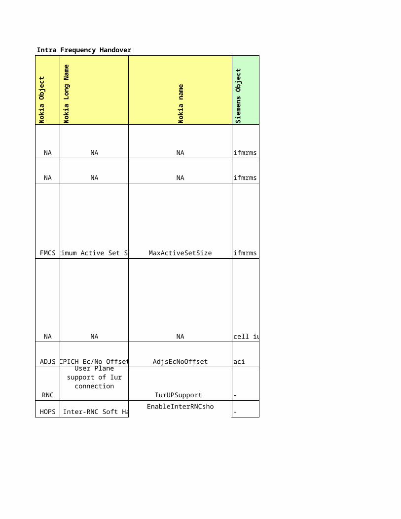
Sie
me
ns
Lo
ng
Na
me
Sie
me
ns
na
me
Eri
cs
so
n O
bje
ct
Filter coefficient ftce UeMeasControl
mmq UeMeasControl
Active set size actset Handover
Cell individual offset cio UtranCell
Cell individual offset cio NA
- - NA
- - NA
Measurement quantity for frequency quality estimate
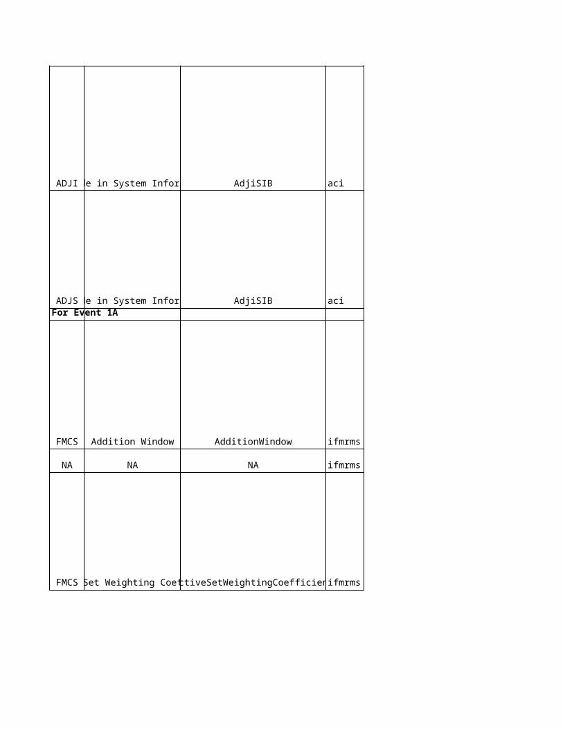
acii NA
acii NA
rng_repo1a UeMeasControl
ofs_reporng NA
W w1a UeMeasControl
Hysteresis (Addition) hyst1a UeMeasControl
Adjacent Cell Information Indicator
Adjacent Cell Information Indicator
Reporting Range (Threshold)
Reporting Range Offset(Improved soft handover failure)
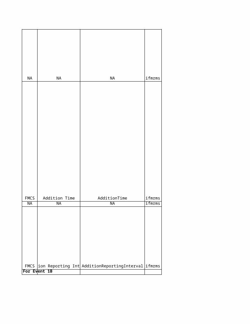
Time to trigger tmtrg1a UeMeasControlAmount of reporting ramnt1a NA
Reporting Interval rintvl1a UeMeasControl
rng_repo1b UeMeasControl
W w1b UeMeasControl
Reporting Range (Threshold)
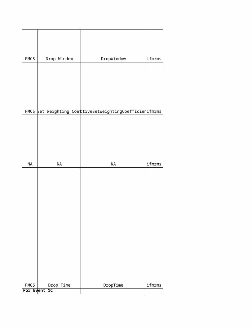
Hysteresis (Deletion) hyst1b UeMeasControl
Time to trigger tmtrg1b UeMeasControl
Hysteresis (Replacement) hyst1c UeMeasControl
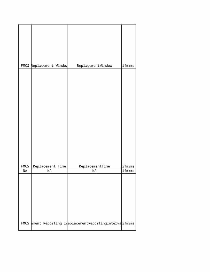
Time to trigger tmtrg1c UeMeasControlAmount of reporting ramnt1c NA
Reporting Interval rintvl1c UeMeasControlFor Event 1D
Hysteresis hyst1d UeMeasControl
NA NA UeMeasControl
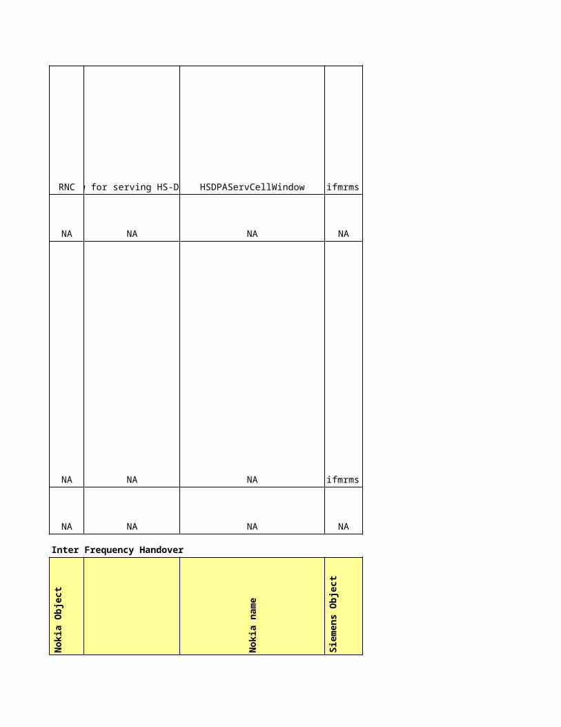
Time to trigger tmtrg1d UeMeasControl
NA NA UeMeasControl
Sie
me
ns
Lo
ng
Na
me
Sie
me
ns
na
me
Eri
cs
so
n O
bje
ct
mq_fqe NA
Filter coefficient ftce UeMeasControl
W used frequency wuf_2a NA
Hysteresis hyst_2a NA
Time to trigger tmtrg_2a NA
W non used frequency wnouf_2a NA
Measurement quantity for frequency quality estimate
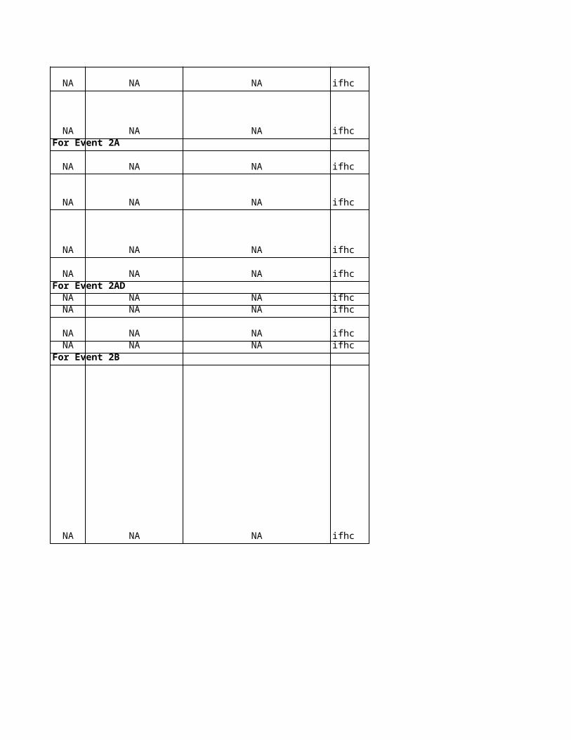
W used frequency wuf_2ad NAHysteresis hyst_2ad NA
Time to trigger tmtrg_2ad NAW non used frequency wnouf_2ad NA
Threshold used frequency thruf_2b UeMeasControl
NA NA UeMeasControl
W used frequency wuf_2b UeMeasControl
Hysteresis hyst_2b UeMeasControl
Time to trigger tmtrg_2b UeMeasControl
Threshold non used frequency thrnouf_2b UeMeasControl
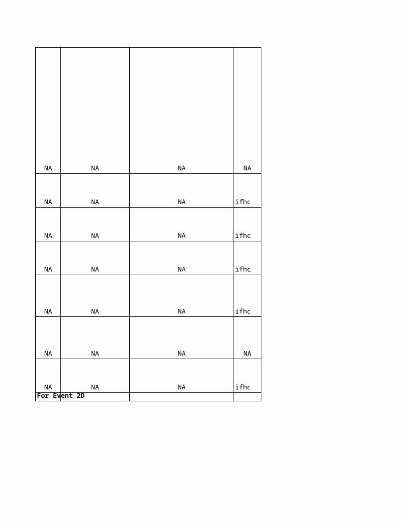
NA NA UeMeasControl
W non used frequency wnouf_2b UeMeasControl
Threshold used frequency thruf_2d UtranCell
NA UtranCell
NA UeMeasControl
NA UeMeasControl
W used frequency wuf_2d UeMeasControl
Hysteresis hyst_2d UeMeasControl
Time to trigger tmtrg_2d UeMeasControl
NA NA UeMeasControl
Threshold used frequency thruf_2f UeMeasControl
NA NA UeMeasControl
W used frequency wuf_2f UeMeasControl
Hysteresis hyst_2f UeMeasControl
Time to trigger tmtrg_2f UeMeasControl
NA NA UeMeasControl
- - NA
- - NA
- - NA
- - NA
- - NA
- - NA
- - NA
- - NA
- - NA
- - NA
- - NA
- - NA
- - NA
- - NA
- - NA
Sie
me
ns
Lo
ng
Na
me
Sie
me
ns
na
me
Eri
cs
so
n O
bje
ct
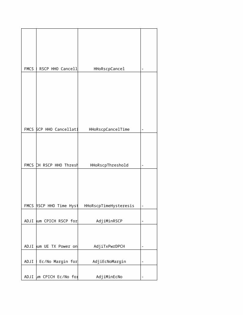
mq_fqe NA
Filter coefficient ftce UeMeasControl
Threshold used frequency thruf_2dug NAW used frequency wuf_2dug NAHysteresis hyst_2dug NA
Time to trigger tmtrg_2dug NA
Threshold used frequency thruf_2f NAW used frequency wuf_2f NAHysteresis hyst_2f NA
Time to trigger tmtrg_2f NA
UTRAN measurement filter coefficient ftce_utran NA
GSM measurement filter coefficient ftce_gsm UeMeasControlBSIC verification required bsic_veri NA
Threshold own system thrown_3a UeMeasControl
frequency quality estimate
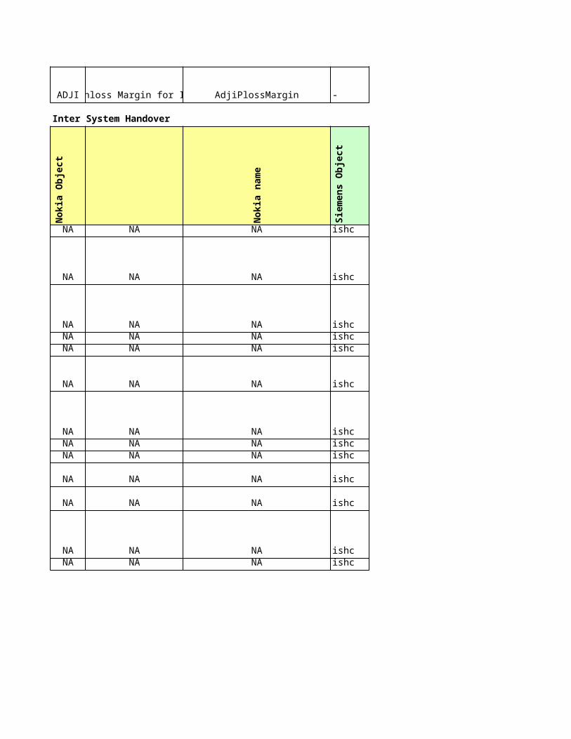
NA NA UeMeasControl
W w_3a UeMeasControl
Time to trigger tmtrg_3a UeMeasControlNetwork Control Mode mode_nc NA
Cell Change Order Allowed cco_alwd NAmq_uqe NAmq_uqe NA
UTRAN quality estimateUTRAN quality estimate
Cell individual offset cio ExternalGsmCell
acii NA
Qrxlevmin qrxlevmin ExternalGsmCell
Adjacent Cell Information Indicator
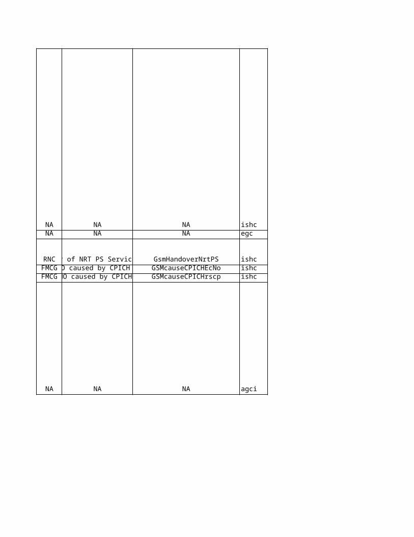
Qoffset1s,n qoffset1 GsmRelation
Threshold other system throth_3a UeMeasControl
Hysteresis hyst_3a UeMeasControl
Band Indicator bandi ExternalGsmCell
NA NA NA
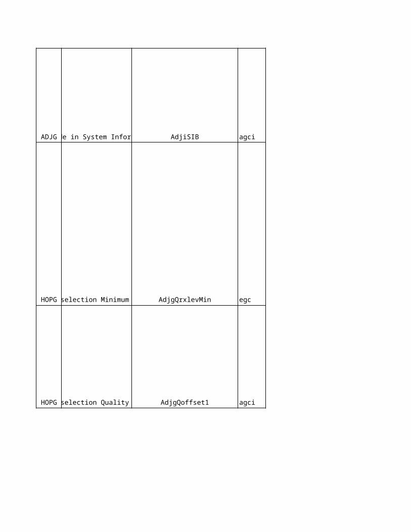
Eri
cs
so
n L
on
g N
am
e
Eri
cs
so
n n
am
e
No
kia
pro
po
se
d
filterCoefficient1 filterCoefficient1 NA
measQuantity1 measQuantity1 NA
maxActiveSet maxActiveSet 3
individualOffset individualOffset NA
NA NA 0
NA NA
Supported (1)
NA NAYes(1)
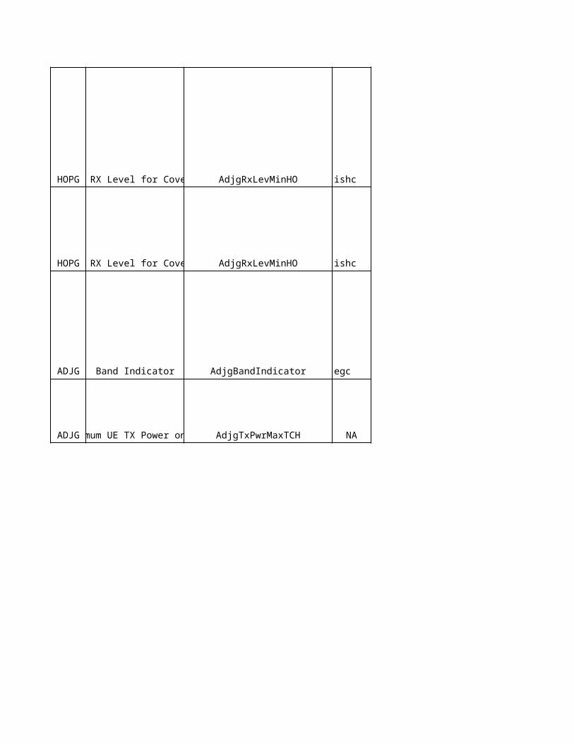
NA NA Yes (1)
NA NA Yes (1)
reportingRange1a reportingRange1a 3
NA NA NA
w1a w1a 0
hysteresis1a hysteresis1a NA
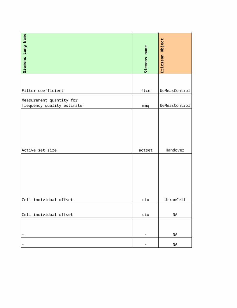
timeToTrigger1a timeToTrigger1a 320NA NA NA
reportingInterval1a reportingInterval1a 1
reportingRange1b reportingRange1b 6
w1b w1b 0
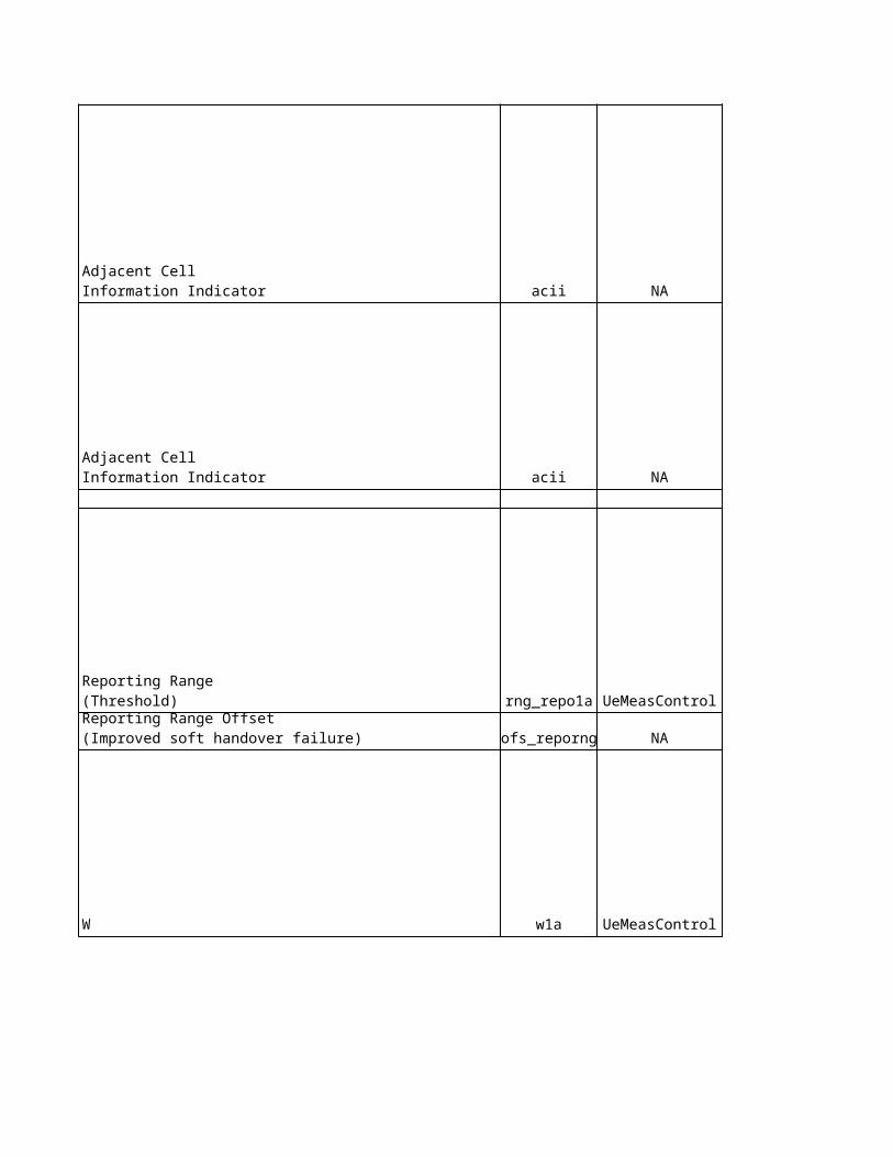
hysteresis1b hysteresis1b NA
timeToTrigger1b timeToTrigger1b 640
hysteresis1c hysteresis1c 2
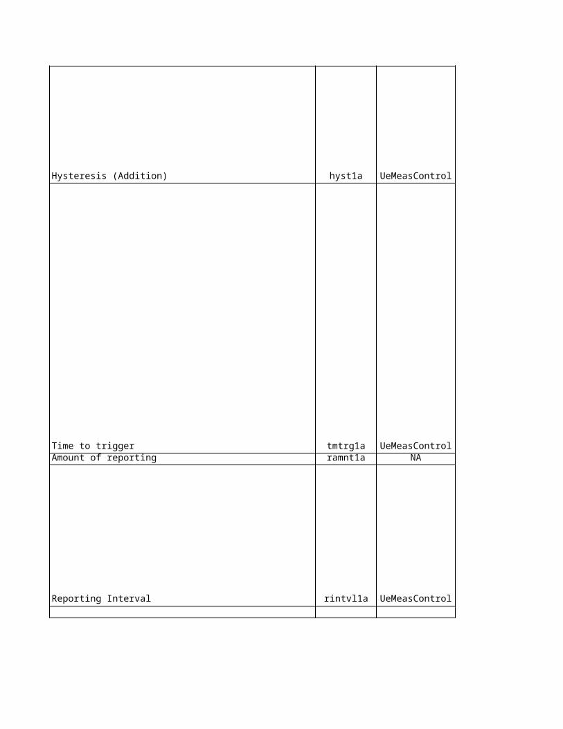
timeToTrigger1c timeToTrigger1c 200NA NA NA
reportingInterval1c reportingInterval1c 1
hysteresis1d hysteresis1d 4
hsHysteresis1d hsHysteresis1d NA
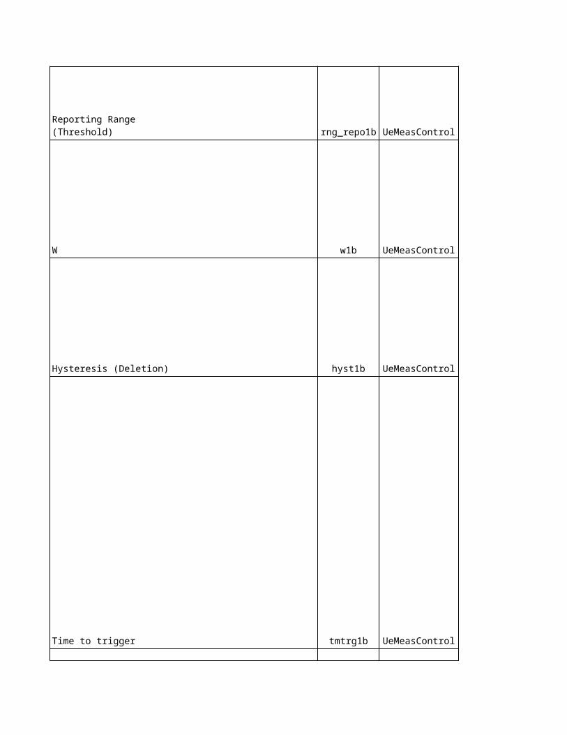
timeToTrigger1d timeToTrigger1d NA
hsTimeToTrigger1d hsTimeToTrigger1d NA
Eri
cs
so
n L
on
g N
am
e
Eri
cs
so
n n
am
e
No
kia
pro
po
se
d
NA NA NA
filterCoefficient2 filterCoefficient2 NA
NA NA NA
NA NA NA
NA NA NA
NA NA NA
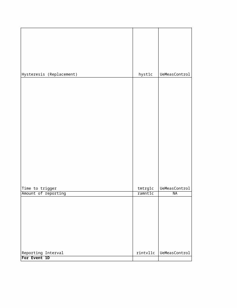
NA NA NANA NA NA
NA NA NANA NA NA
usedFreqRelThresh4_2bEcno usedFreqRelThresh4_2bEcno NA
usedFreqRelThresh4_2bRscp usedFreqRelThresh4_2bRscp NA
usedFreqW4_2b usedFreqW4_2b NA
hyst4_2b hyst4_2b NA
timeTrigg4_2b timeTrigg4_2b NA
nonUsedFreqThresh4_2bEcno nonUsedFreqThresh4_2bEcno NA
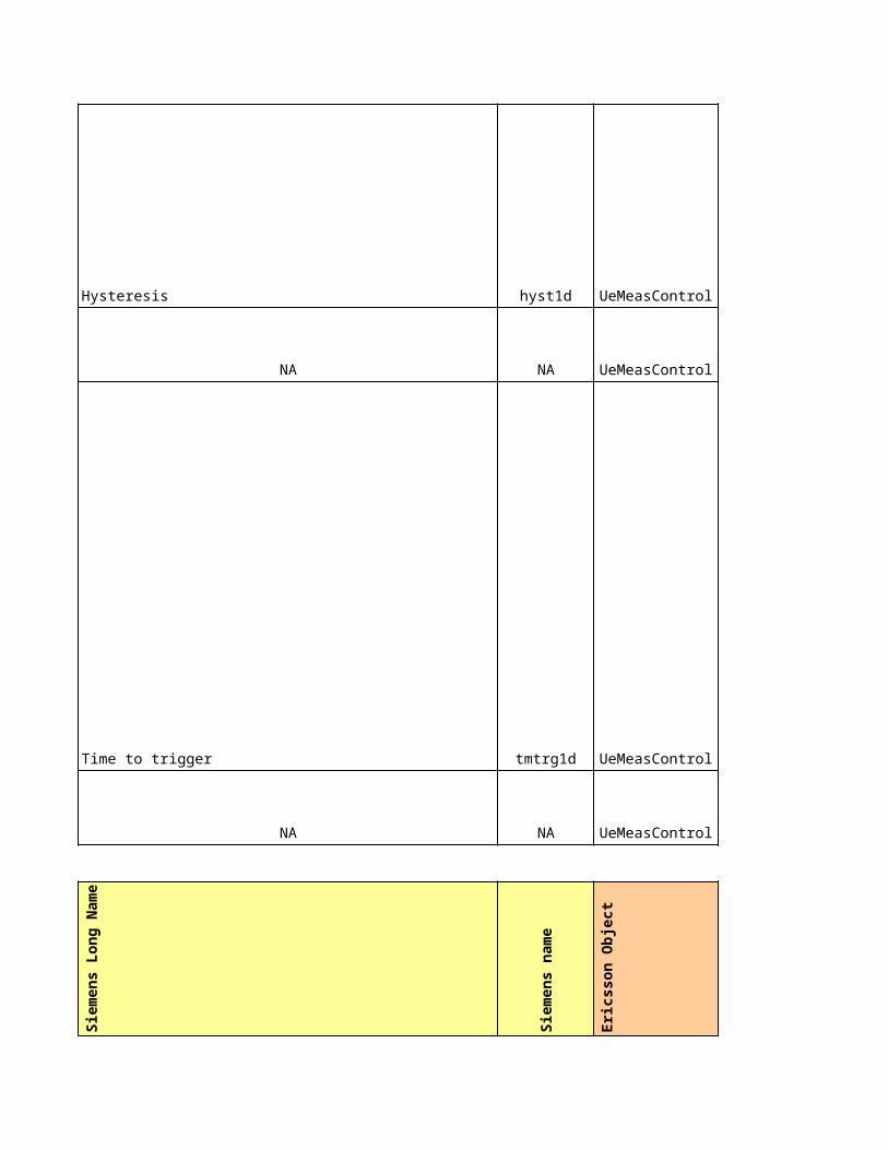
nonUsedFreqThresh4_2bRscp nonUsedFreqThresh4_2bRscp NA
nonUsedFreqW4_2b nonUsedFreqW4_2b NA
usedFreqThresh2dEcno usedFreqThresh2dEcno NA
usedFreqThresh2dRscp usedFreqThresh2dRscp NA
usedFreqThresh2dEcnoDrnc usedFreqThresh2dEcnoDrnc NA
usedFreqThresh2dRscpDrnc usedFreqThresh2dRscpDrnc NA
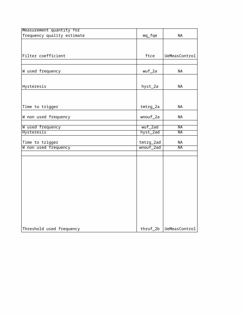
usedFreqW2d usedFreqW2d NA
hysteresis2d hysteresis2d NA
timeToTrigger2dEcno timeToTrigger2dEcno NA
timeToTrigger2dRscp timeToTrigger2dRscp NA
usedFreqRelThresh2fEcno usedFreqRelThresh2fEcno NA
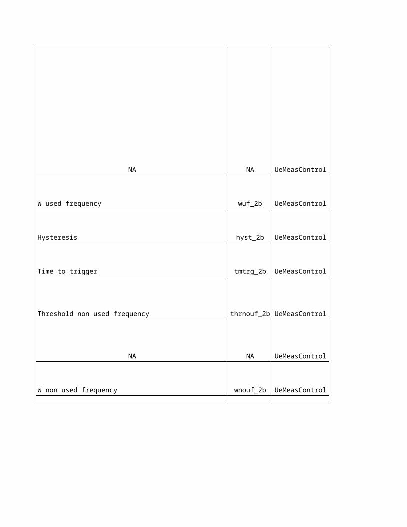
usedFreqRelThresh2fRscp usedFreqRelThresh2fRscp NA
usedFreqW2f usedFreqW2f NA
hysteresis2f hysteresis2f NA
timeToTrigger2fEcno timeToTrigger2fEcno NA
timeToTrigger2fRscp timeToTrigger2fRscp NA
NA NA Enabled(1)
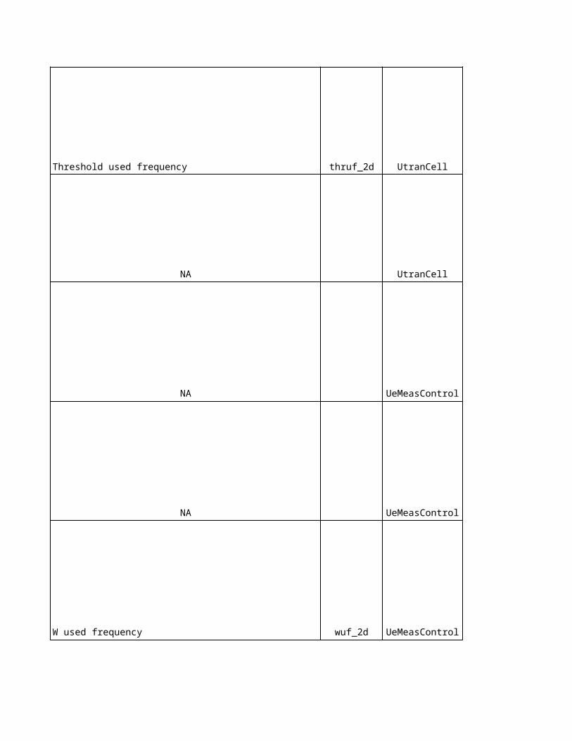
NA NA
NA NA -9
NA NA 640
NA NA -12
NA NA 200
NA NA
1st carrier:Disable(0)2nd carrier:Enabled(1)
1st carrier: -962nd carrier: -93
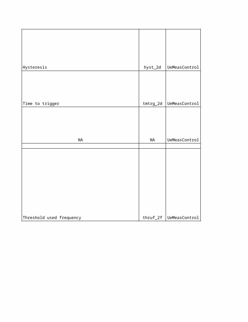
NA NA 640
NA NA
NA NA 200
NA NA -96
NA NA 24
NA NA 2
NA NA -10
NA NA 2
Eri
cs
so
n L
on
g N
am
e
Eri
cs
so
n n
am
e
No
kia
pro
po
se
d
1st carrier: -1012nd carrier: -98
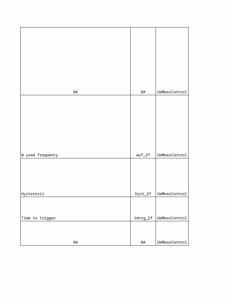
NA NA NA
utranFilterCoefficient3 utranFilterCoefficient3 NA
NA NA NANA NA NANA NA NA
NA NA NA
NA NA NANA NA NANA NA NA
NA NA NA
NA NA NA
gsmFilterCoefficient3 gsmFilterCoefficient3 NANA NA NA
utranRelThresh3aEcno utranRelThresh3aEcno NA
utranRelThresh3aRscp utranRelThresh3aRscp NA
utranW3a utranW3a NA
timeToTrigger3a timeToTrigger3a NANA NA NA
NA NANA NA Disable(0)NA NA Enabled(1)
individualOffset individualOffset NA
NA NA Yes (1)
qRxLevMin qRxLevMin -101
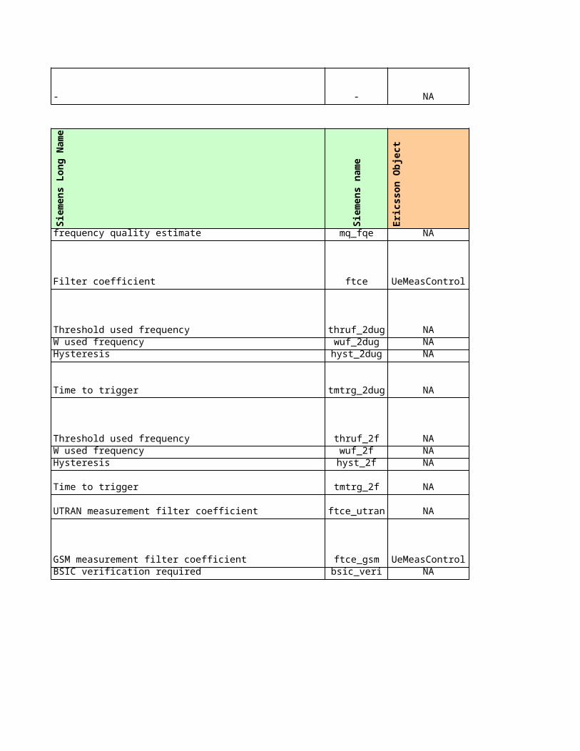
qOffset1sn qOffset1sn 0
gsmThresh3a gsmThresh3a -100
hysteresis3a hysteresis3a -100
bandIndicator bandIndicator -
NA NA 33
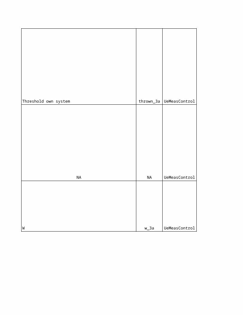
Sie
me
ns
cu
rre
nt
Eri
cs
so
n c
urr
en
t
Ag
ree
d
No
kia
Un
it
Sie
me
ns
Un
it
2 2 - -
ecn0 2=EcNo - -
3 3 - -
- 0 dB dB
0 NA dB dB
- NA - -
- NA - -
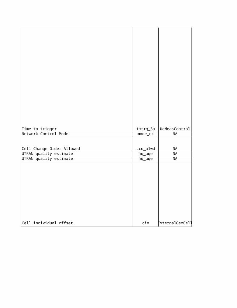
all NA - -
all NA - -
3 6 = 3dB dB dB
3 NA dB dB
0 0 - -
0 0 dB dB
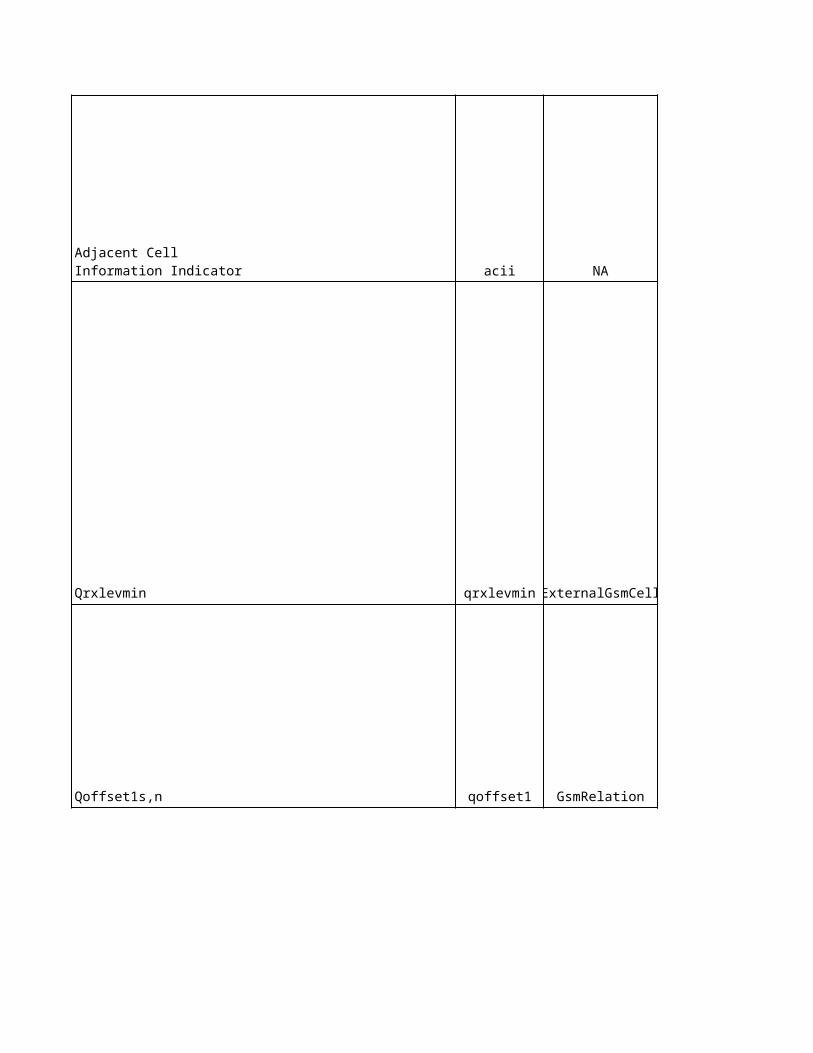
320 11 = 320ms ms ms2 NA 0 0
1000 3 = 1s s ms
6 10 = 5dB dB dB
0 0 - -
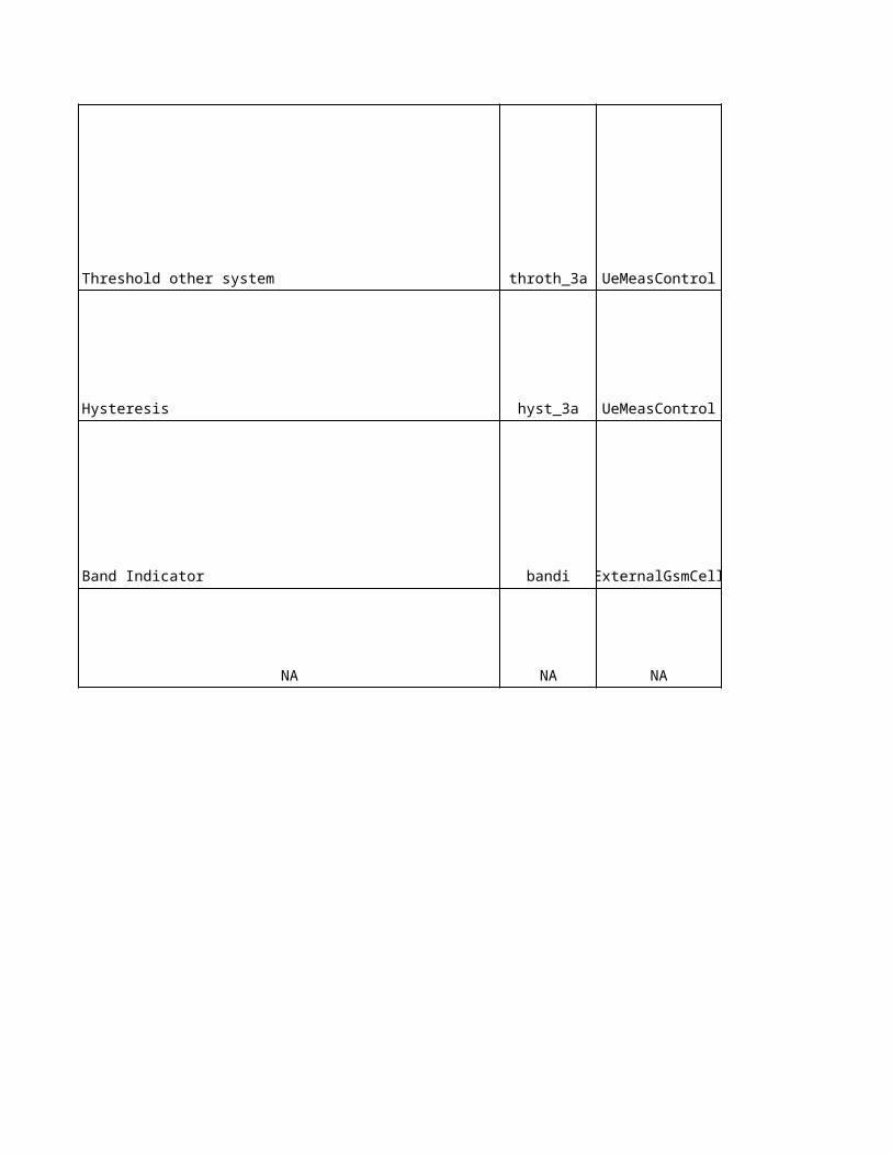
0 0 dB dB
640 12 = 640ms ms ms
2 2 = 1dB dB dB
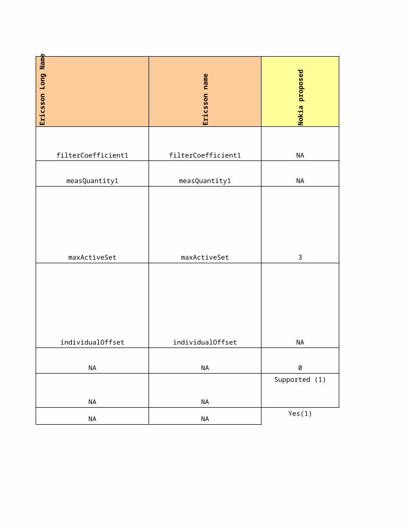
200 11 = 320ms ms ms2 NA 0 0
1000 3 = 1s s ms
4 15 = 7.5dB dB dB
NA 10 = 1dB NA NA

640 14 = 2560ms ms ms
NA 640 NA NA
Sie
me
ns
cu
rre
nt
Eri
cs
so
n c
urr
en
t
Ag
ree
d
No
kia
Un
it
Sie
me
ns
Un
it
ecn0 NA - -
2 2 - -
0.1 NA - -
4 NA dB dB
640 NA ms ms
0.1 NA - -

0.1 NA - -6 NA dB dB
640 NA ms ms0.1 NA - -
-12 -1
NA -3 NA NA
0 0 - -
0 10 = 1dB dB dB
640 100 ms ms
-10 -13
dBm if "mq_fqe=rscp"
dB if if "mq_fqe=ecn0"
dBm if "mq_fqe=rscp"
dB if if "mq_fqe=ecn0"
dBm if "mq_fqe=rscp"
dB if if "mq_fqe=ecn0"
dBm if "mq_fqe=rscp"
dB if if "mq_fqe=ecn0"
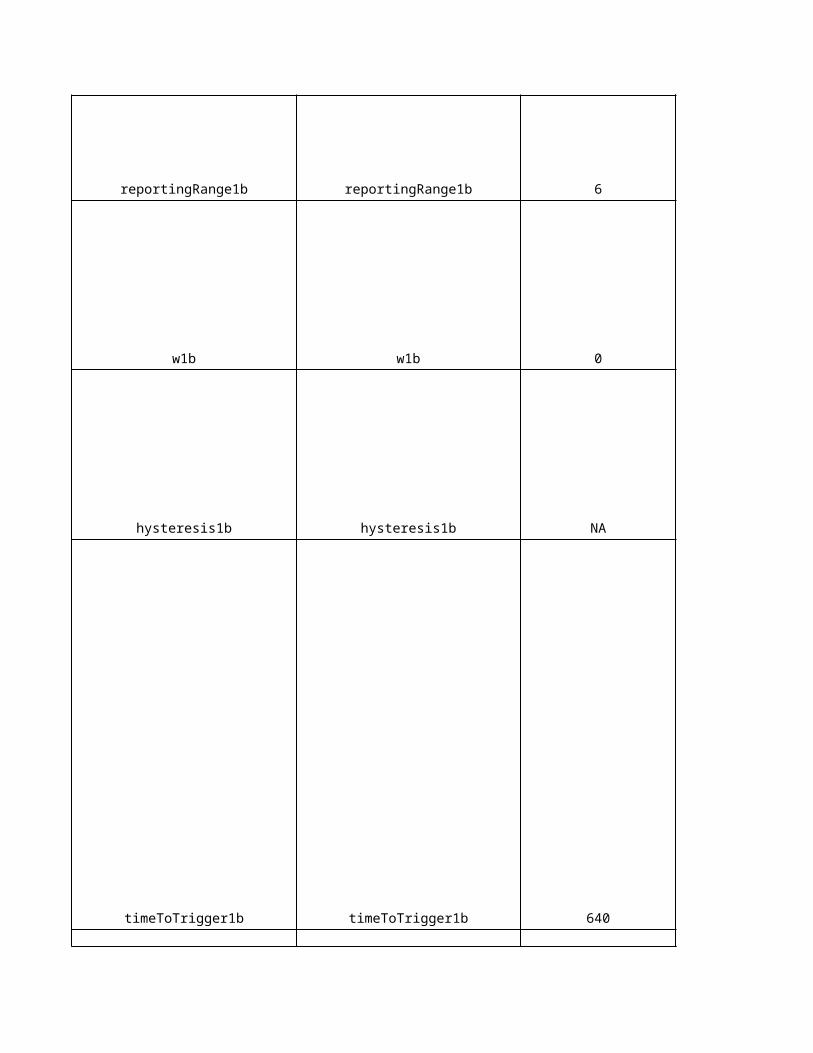
NA -105 NA NA
0 0 - -
-12 -12
NA -104 NA NA
NA -12 NA NA
NA -100 NA NA
dBm if "mq_fqe=rscp"
dB if if "mq_fqe=ecn0"
dBm if "mq_fqe=rscp"
dB if if "mq_fqe=ecn0"
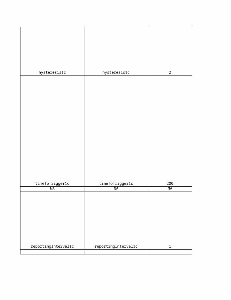
0 0 - -
0 0 dB dB
200 320 ms ms
NA 320 NA NA
-9 3
dBm if "mq_fqe=rscp"
dB if if "mq_fqe=ecn0"
dBm if "mq_fqe=rscp"
dB if if "mq_fqe=ecn0"
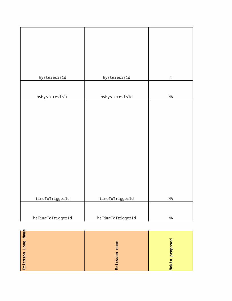
NA 3 NA NA
0 0 - -
0 0 dB dB
640 1280 ms ms
NA 1280 NA NA
- NA -
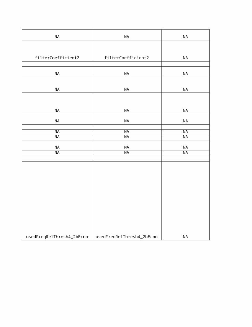
- NA -
- NA dB -
- NA ms -
- NA dB -
- NA ms -
- NA dBm -
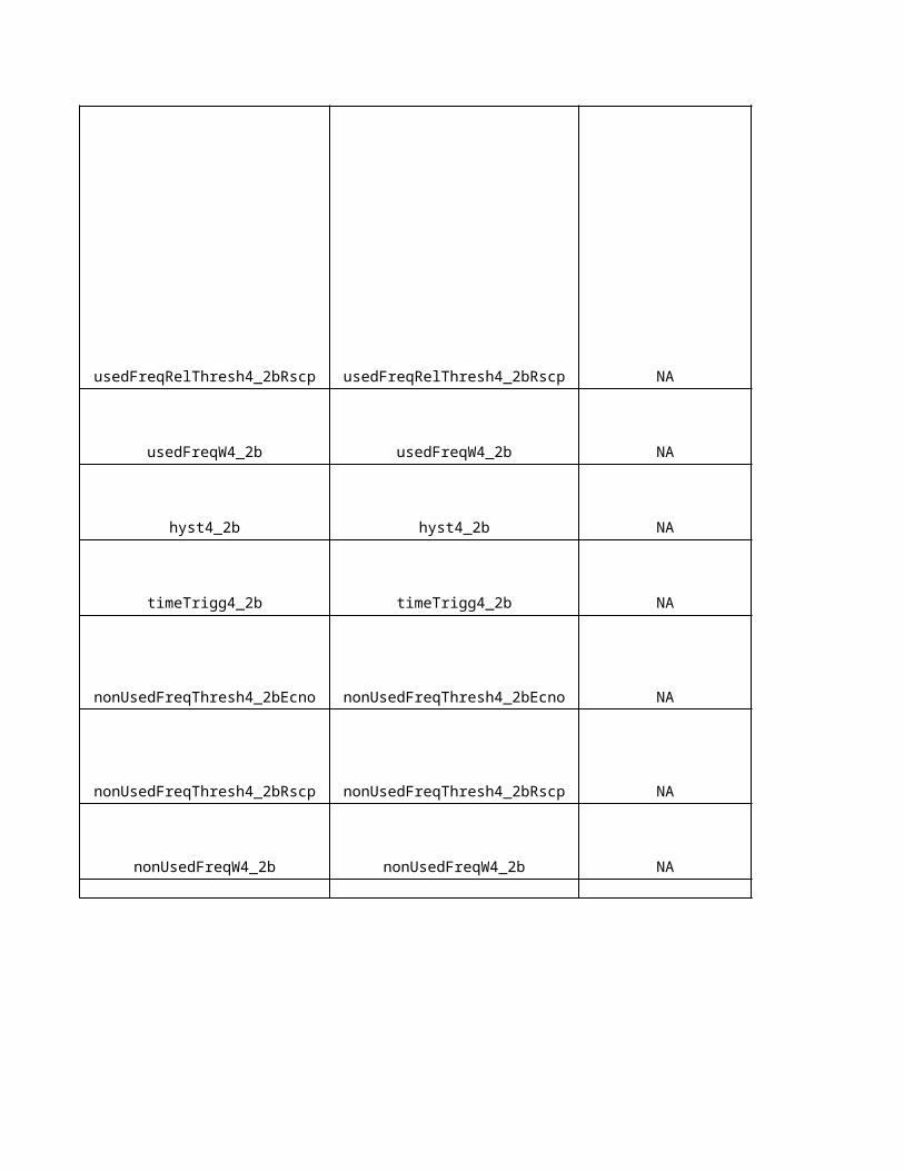
- NA ms -
- NA dBm -
- NA ms -
- NA dBm -
- NA dBm -
- NA dB -
- NA dB -
- NA dB -
Sie
me
ns
cu
rre
nt
Eri
cs
so
n c
urr
en
t
Ag
ree
d
No
kia
Un
it
Sie
me
ns
Un
it
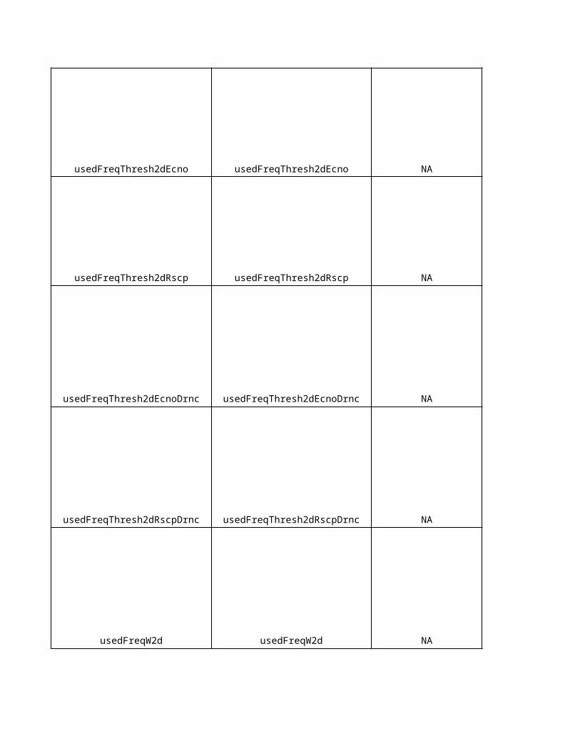
rscp NA - -
2 2 - -
-102 NA0 NA - -2 NA dB dB
200 NA ms ms
-97 NA0 NA - -2 NA dB dB
1280 NA ms ms
2 NA - -
2 1 - -rqr NA - -
-100 2 dB dB
dBm if "mq_fqe=rscp"
dB if if "mq_fqe=ecn0"
dBm if "mq_fqe=rscp"
dB if if "mq_fqe=ecn0"
dBm if "mq_fqe=rscp"
dB if if "mq_fqe=ecn0"
dBm if "mq_fqe=rscp"
dB if if "mq_fqe=ecn0"
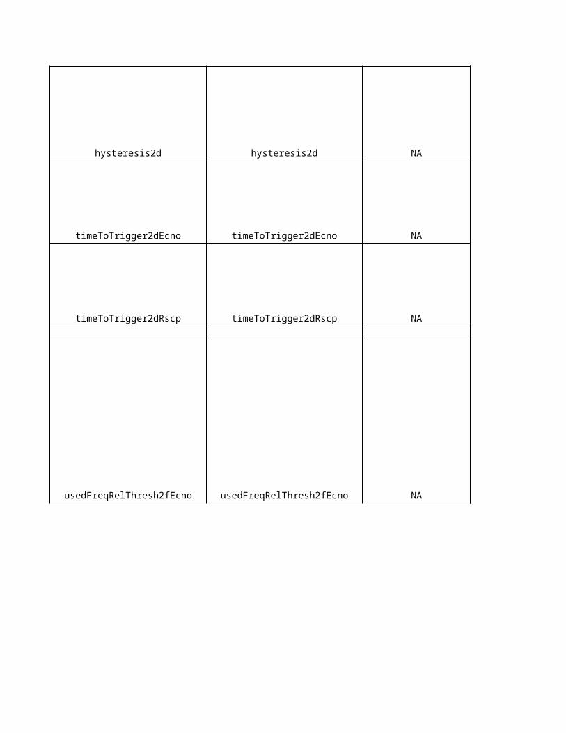
NA 3 NA NA
0 0 - -
60 6 = 100ms ms ms0 - -
true NA - -rscp NA - -rscp NA - -
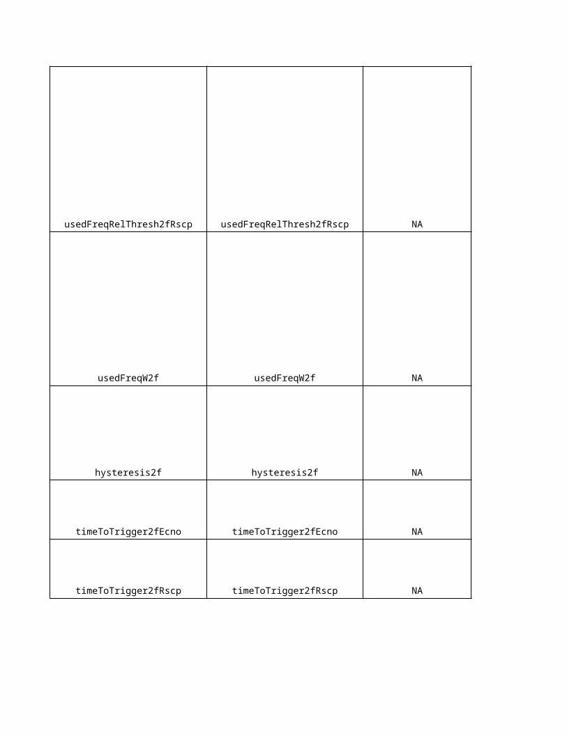
0 0 dB dB
all NA - -
-101 -105 dBm dBm
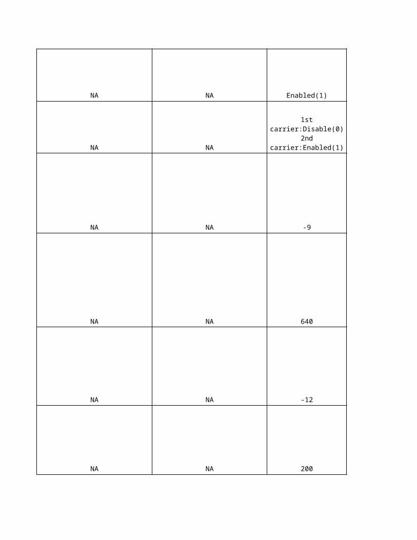
0 7 dB dB
-100 -95 dBm dBm
0 0 dB dB
- 0 = DCS1800 - -
NA NA dBm -
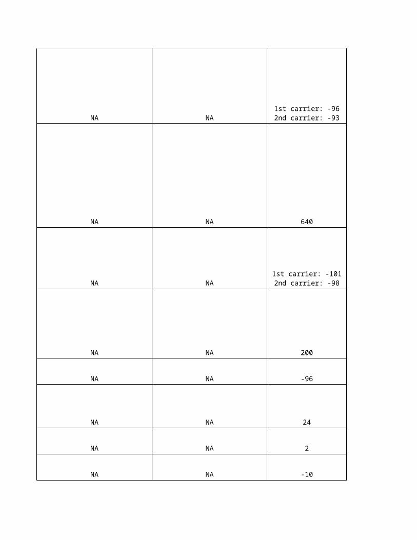
Eri
cs
so
n U
nit
-
-
-
dB
NA
NA
NA
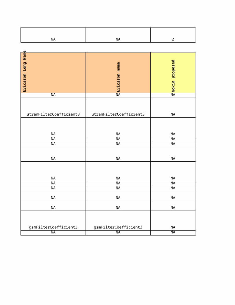
NA
NA
0.5dB
NA
-
dB
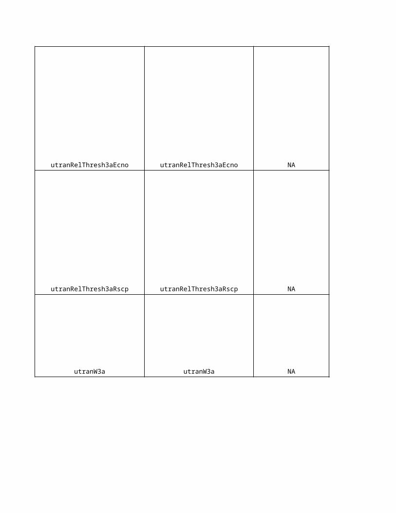
msNA
s
dB
-
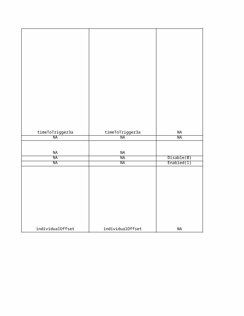
dB
ms
dB
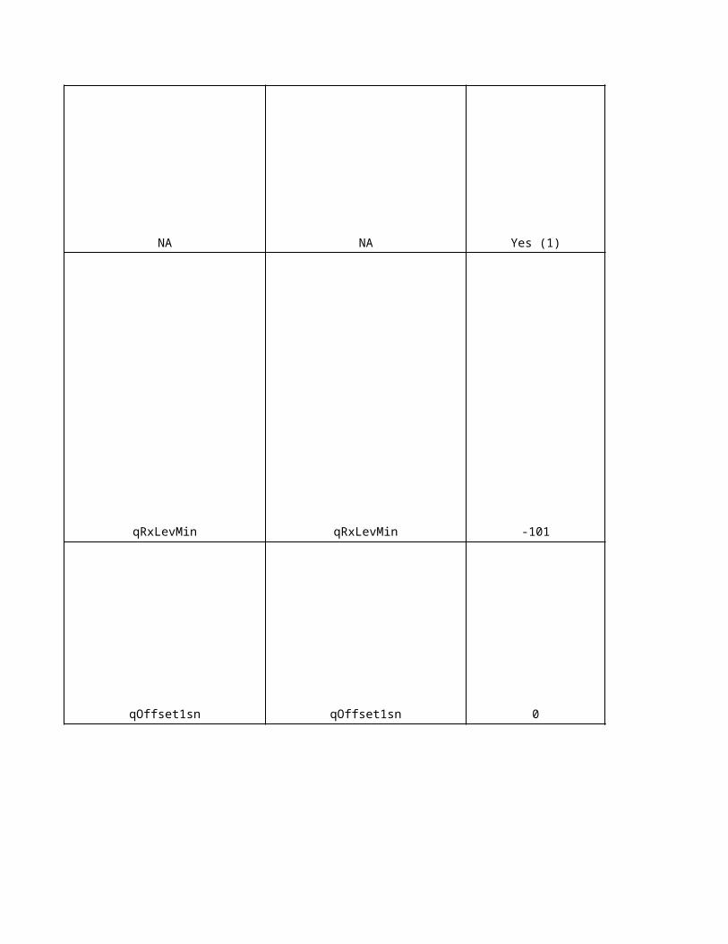
msNA
s
dB
dB
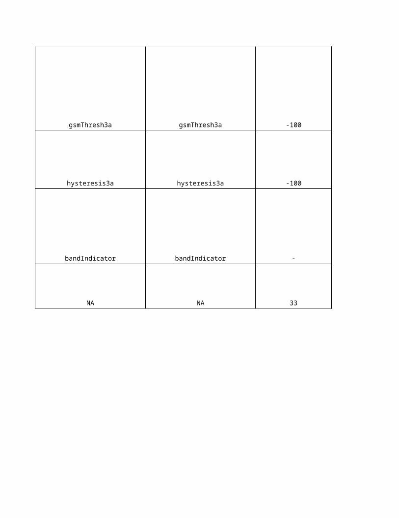
ms
ms
Eri
cs
so
n U
nit
NA
-
NA
NA
NA
NA
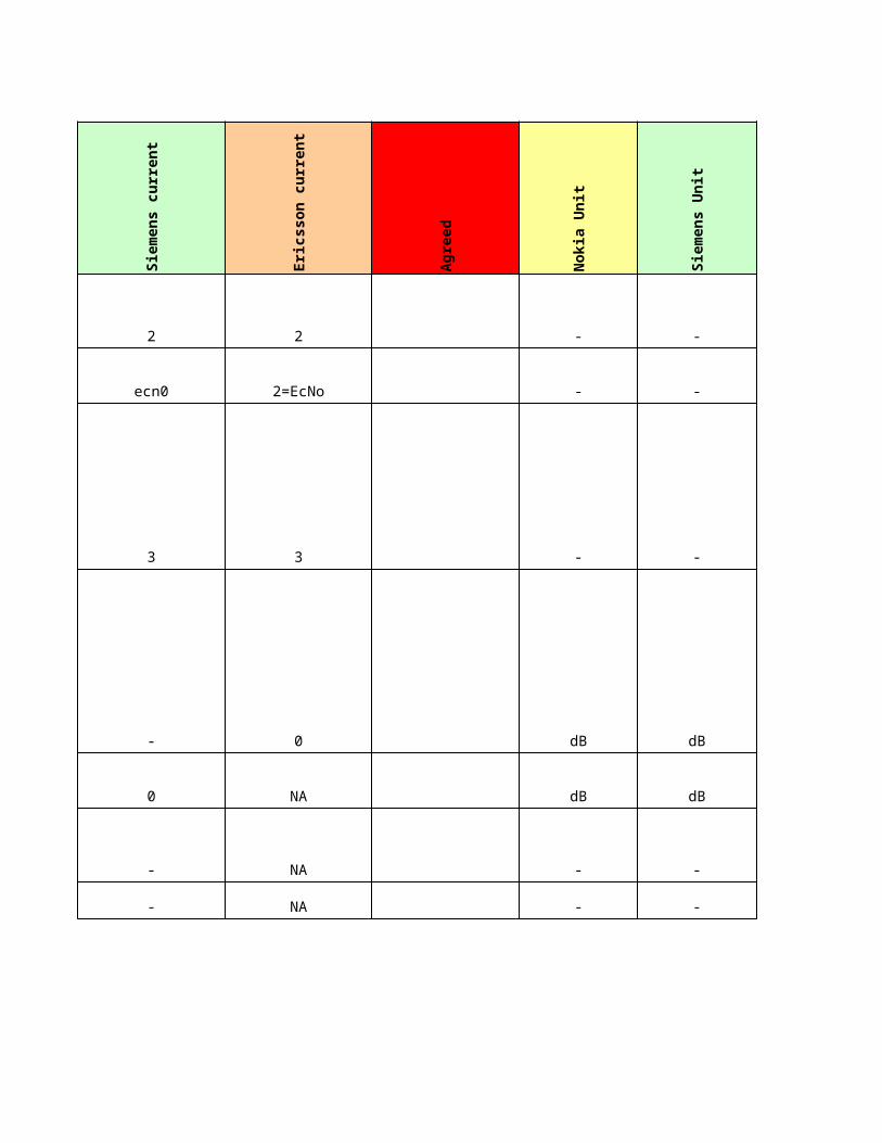
NANA
NANA
dB
dB
-
dB
ms
dB
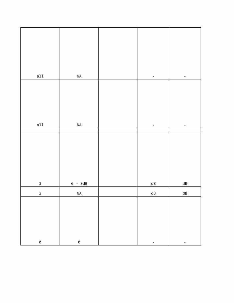
dBm
-
dB
dBm
dB
dBm
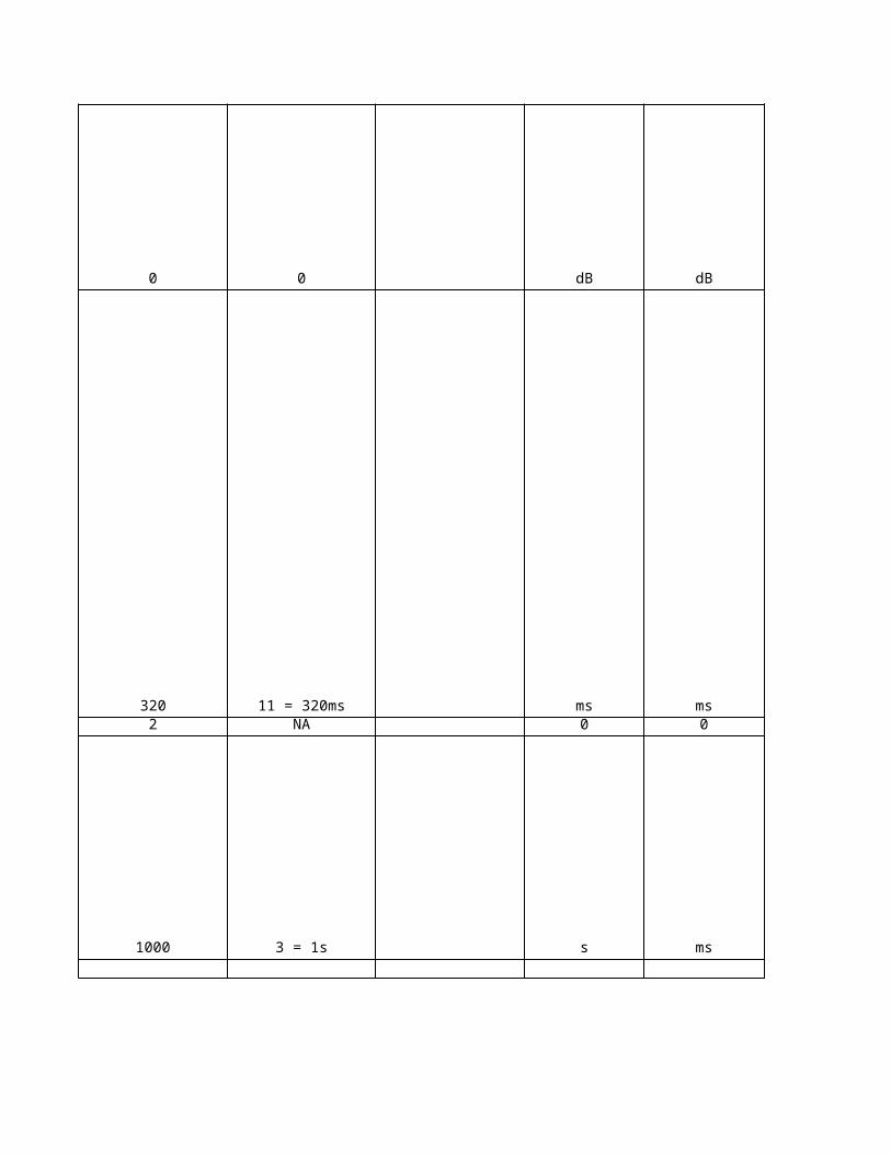
-
dB
ms
ms
dB
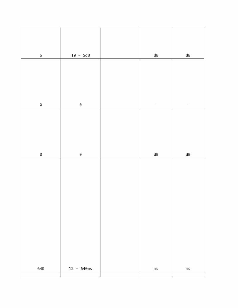
dB
-
dB
ms
ms
NA
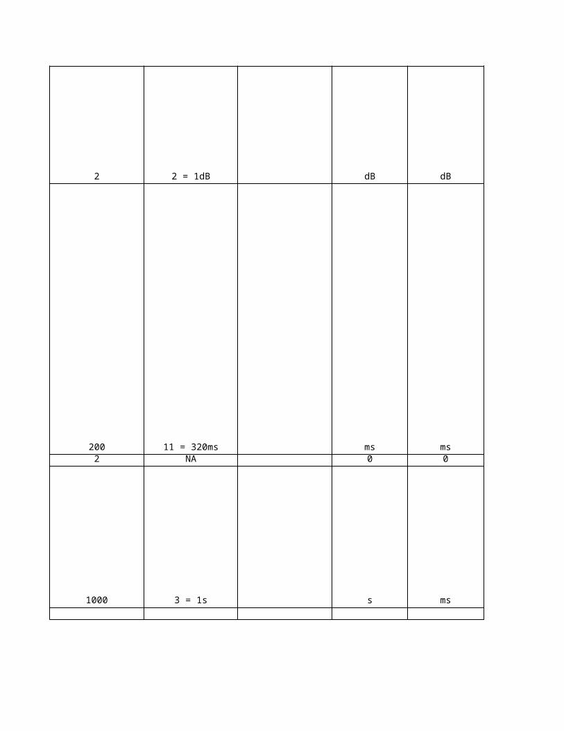
NA
NA
NA
NA
NA
NA
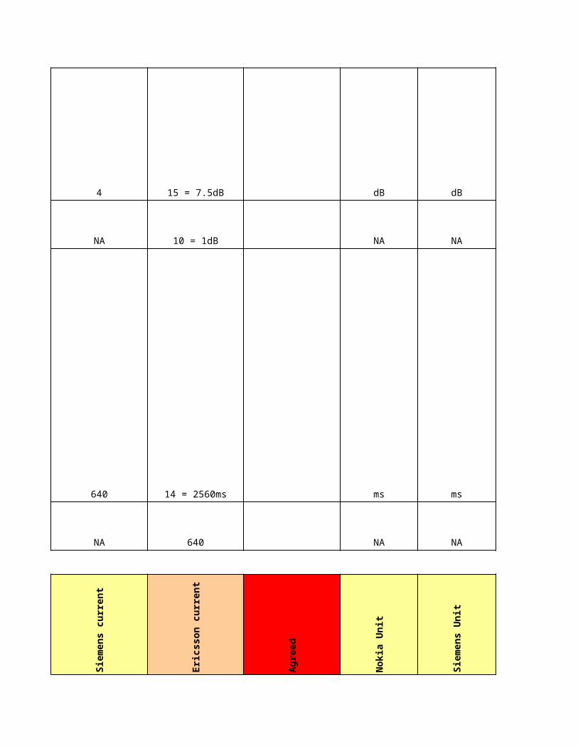
NA
NA
NA
NA
NA
NA
NA
NA
Eri
cs
so
n U
nit
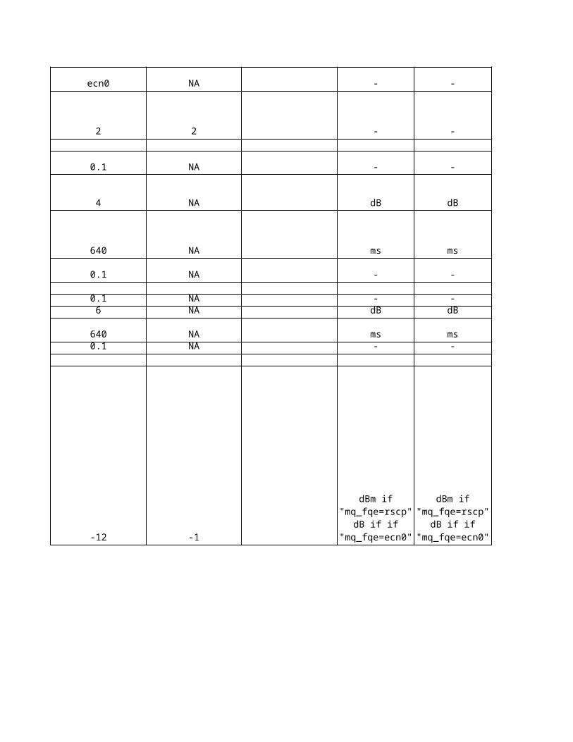
NA
-
NANANA
NA
NANANA
NA
NA
-NA
dB
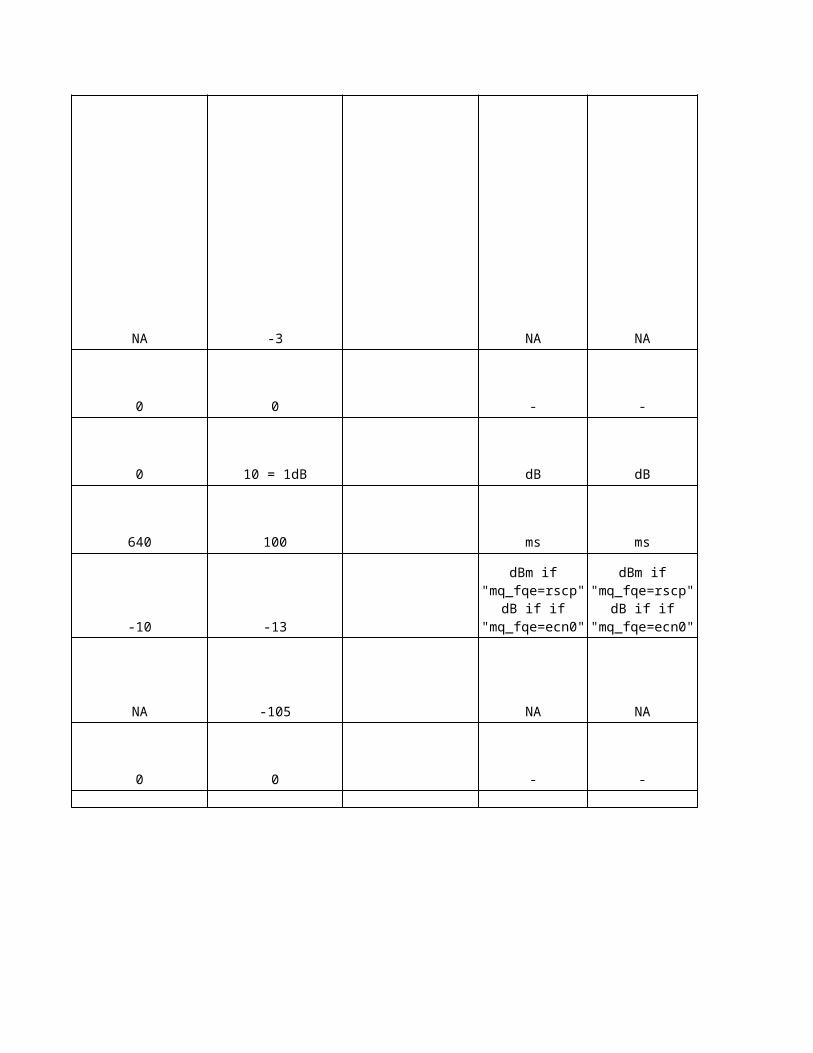
dB
-
msNA
NANA
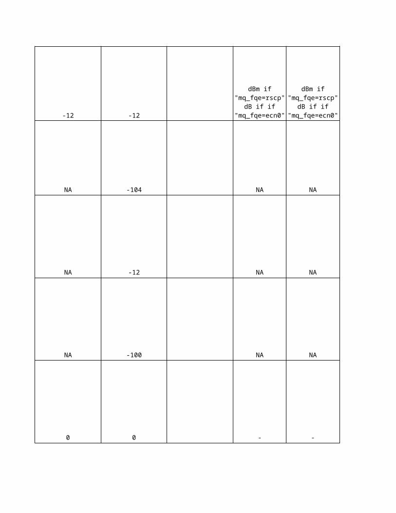
dB
NA
dBm
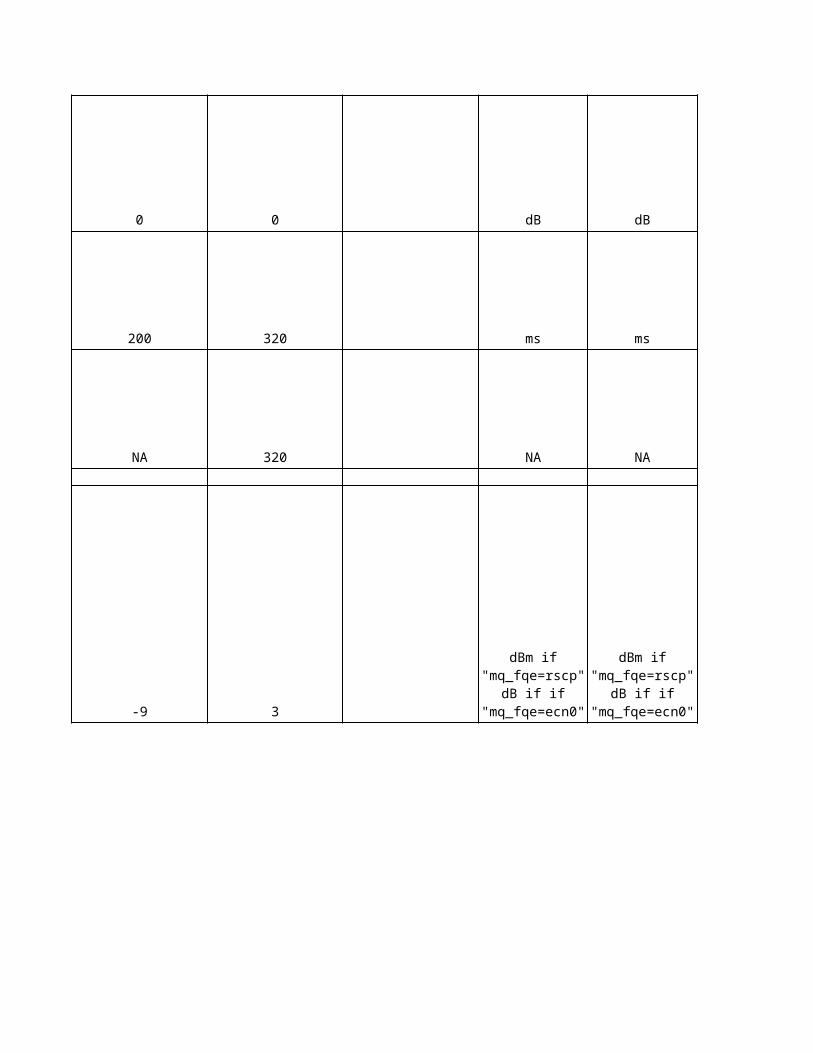
dB
dBm
dB
-
NA
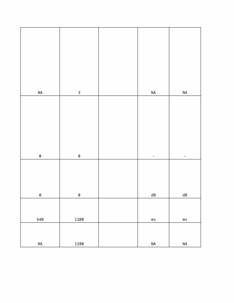
No
kia
De
sc
rip
tio
n
NA
NA
NA
This parameter determines the maximum number of cells which can participate in a soft/softer handover. Reporting deactivation threshold indicates the maximum number of cells allowed in the active set in order for the event 1A to trigger. The RNC calculates the deactivation threshold from the parameter MaxActiveSetSize: Reporting Deactivation Threshold = MaxActiveSetSize - 1 Reporting Deactivation Threshold parameter is part of System Information Block 11/12. Replacement activation threshold information element indicates the minimum number of cells allowed in the active set in order for the event 1C to trigger. The threshold equals to the maximum size of the active set which is controlled with the parameter MaxActiveSetSize. Replacement Activation Threshold parameter is part of System Information Block 11/12.
The CPICH Ec/No Offset determines an offset value, which the UE adds to the CPICH Ec/No measurement result of the neighbouring cell before it compares the Ec/No value with the reporting criteria.
This parameter indicates a user plane procedure support of the Iur connection. This information is given separately for each neighboring RNC.If the user plane is not supported between SRNC and DRNC, initiation of a soft handover procedure is not possible.
Parameter indicates whether the neighbouring cell can participate in a soft handover, if it is controlled by a RNC other than the local RNC.
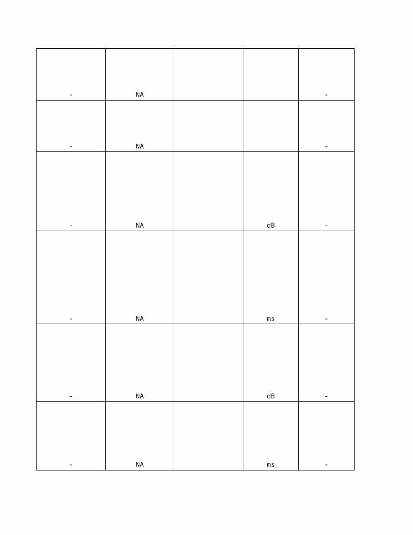
NA
NA
This parameter indicates whether the inter-frequency neighbour cell is included in the System Information Block 11&12&18 for the cell selection and re-selection procedures. The inter-frequency neighbour cell is included in the system information when the value of the parameter is "yes". The maximum number of inter-frequency neighbour cells that can be included in the System Information Block 11&12&18 is 32. The neighbouring cells can be distributed to up to two FDD carriers (ref. 3GPP TS 25.133). If the total number of intra-frequency, inter-frequency and GSM neighbour cells, which are included in the System Information, exceeds the physical size of SIB data, the NBAP interface is not able to pack the neighbour cell information into the SIB data and the scheduling of the system information blocks fails. The cell is blocked by the system and an alarm 7771 WCDMA CELL OUT OF USE (BCCH scheduling error) is reported for the cell. Note: The parameter AdjiSIB does not affect inter-frequency measurements in CELL_DCH state of connected mode. That is, all inter-frequency neighbour cells are monitored for the inter-frequency handover regardless of the value of the parameter AdjiSIB.
The parameter indicates whether the intra-frequency neighbour cell is included in the System Information Block 11&12&18 for the cell selection and re-selection procedures. The intra-frequency neighbour cell is included in the system information when the value of the parameter is "yes". If the total number of intra-frequency, inter-frequency and GSM neighbour cells, which are included in the System Information, exceeds the physical size of SIB data, the NBAP interface is not able to pack the neighbour cell information into the SIB data and the scheduling of the system information blocks fails. The cell is blocked by the system and an alarm 7771 WCDMA CELL OUT OF USE (BCCH scheduling error) is reported for the cell. Note: The parameter AdjsSIB does not affect intra-frequency measurements in CELL_DCH state of connected mode. That is, all intra-frequency neighbour cells are monitored for the soft(er) handover regardless of the value of the parameter AdjsSIB.
Addition Window determines the relative threshold (A_Win) used by the UE to calculate the reporting range of event 1A. The threshold is either relative to the CPICH Ec/No measurement result of the best active set cell (M_best), or to the sum of active set measurement results (M_sum), depending on the value of the parameter Active Set Weighting Coefficient (W). When the CPICH Ec/No measurement result of a monitored cell (M_new) enters the reporting range, the UE transmits a Measurement Report to the RNC in order to add the monitored cell into the active set: M_new >= W * M_sum + ( 1 - W )* M_best - A_Win
Active Set Weighting Coefficient (W) is used to weight either the measurement result of the best active set cell (M_best) or the sum of measurement results of all active set cells (M_sum) when the UE calculates the reporting range for the events 1A (cell addition) and 1B (dropping of cell). The formula is: W * M_sum + ( 1 - W )* M_best
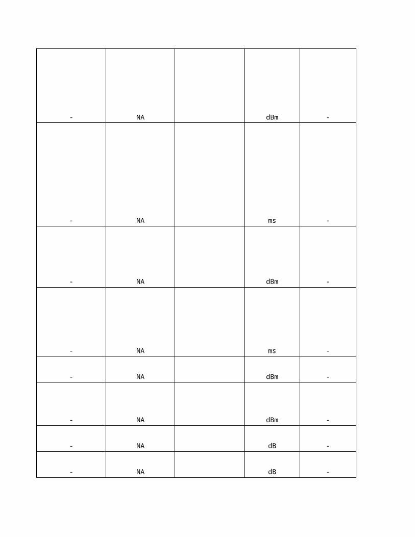
NA
When a monitored cell enters the reporting range (addition window), the cell must continuously stay within the reporting range for a given period of time before the UE can send a Measurement Report to the RNC in order to add the cell into the active set (event 1A). The length of this period is controlled by the parameter Addition Time.
When a monitored cell enters the reporting range and triggers event 1A (cell addition), the UE transmits a Measurement Report to the RNC. If the RNC is not able to add the monitored cell to the active set, the UE continues reporting after the initial report by reverting to periodical measurement reporting. The parameter Addition Reporting Interval determines the interval between periodical measurement reports when such reporting is triggered by the event 1A.
Drop Window determines the relative threshold (D_Win) which is used by the UE to calculate the reporting range of event 1B. The threshold is either relative to the CPICH Ec/No measurement result of the best active set cell (M_best) or to the sum of active set measurement results (M_sum), depending on the value of the parameter Active Set Weighting Coefficient (W). When the CPICH Ec/No measurement result of an active set cell (M_old) leaves the reporting range, the UE transmits a Measurement Report to the RNC in order to remove the cell from the active set: M_old <= W * M_sum + ( 1 - W )* M_best - D_Win
Active Set Weighting Coefficient (W) is used to weight either the measurement result of the best active set cell (M_best) or the sum of measurement results of all active set cells (M_sum) when the UE calculates the reporting range for the events 1A (cell addition) and 1B (dropping of cell). The formula is: W * M_sum + ( 1 - W )* M_best
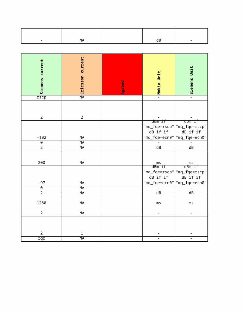
NA
When an active set cell leaves the reporting range (drop window), the cell must continuously stay outside the reporting range for a given period of time before the UE can send a Measurement Report to the RNC in order to remove the cell from the active set (event 1B). The length of this period is controlled by the parameter Drop Time.
When the number of cells in the active set has reached the maximum specified by the parameter MaxActiveSetSize and a monitored cell becomes better than an active set cell, the UE transmits a Measurement Report to the RNC in order to replace the active cell with the monitored cell (event 1C). The parameter Replacement Window determines the margin by which the CPICH Ec/No measurement result of the monitored cell (MNew) must exceed the CPICH Ec/No measurement result of the an active set cell (MInAS) before the UE can send the event 1C triggered Measurement Report to the RNC: MNew >= MInAs + ReplacementWindow / 2
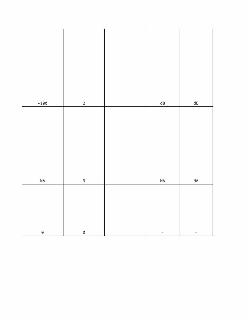
NA
NA
When the number of cells in the active set has reached the maximum, and a monitored cell enters the reporting range (replacement window), the monitored cell must continuously stay within the reporting range for a given period of time before the UE can send a Measurement Report to the RNC in order to replace an active set cell with the monitored cell (event 1C). The length of this period is controlled by the parameter Replacement Time.
When the number of cells in the active set has reached the maximum, and a monitored cell becomes better than an active set cell, the UE transmits a Measurement Report to the RNC in order to replace the active cell with the monitored cell (event 1C). If the RNC is not able to replace the active cell with the monitored cell, the UE continues reporting after the initial report by reverting to periodical measurement reporting. The parameter Replacement Reporting Interval determines the interval of periodical measurement reports when such reporting is triggered by the event 1C.
Parameter determines the maximum allowed difference between the best cell and the serving HS-DSCH cell. The window is relative to the best cell in the active set. If the serving HS-DSCH cell change is outside of the window, serving HS-DSCH cell change procedure is initiated. The measured quantity is CPICH Ec/No, which is received periodically from the UE.
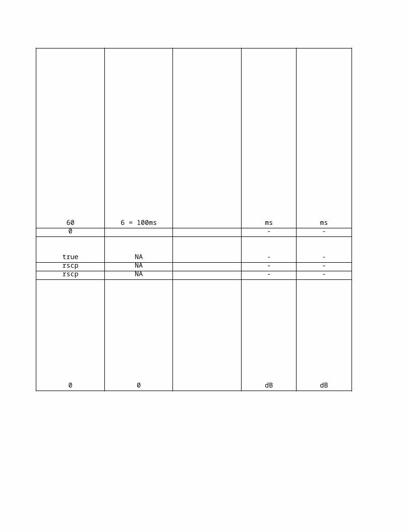
NA
NA
No
kia
De
sc
rip
tio
n
NA
NA
NA
NA
NA
NA
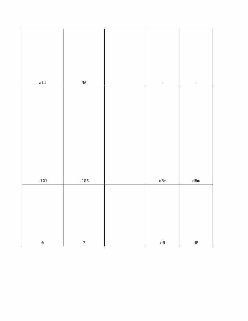
NANA
NANA
NA
NA
NA
NA
NA
NA
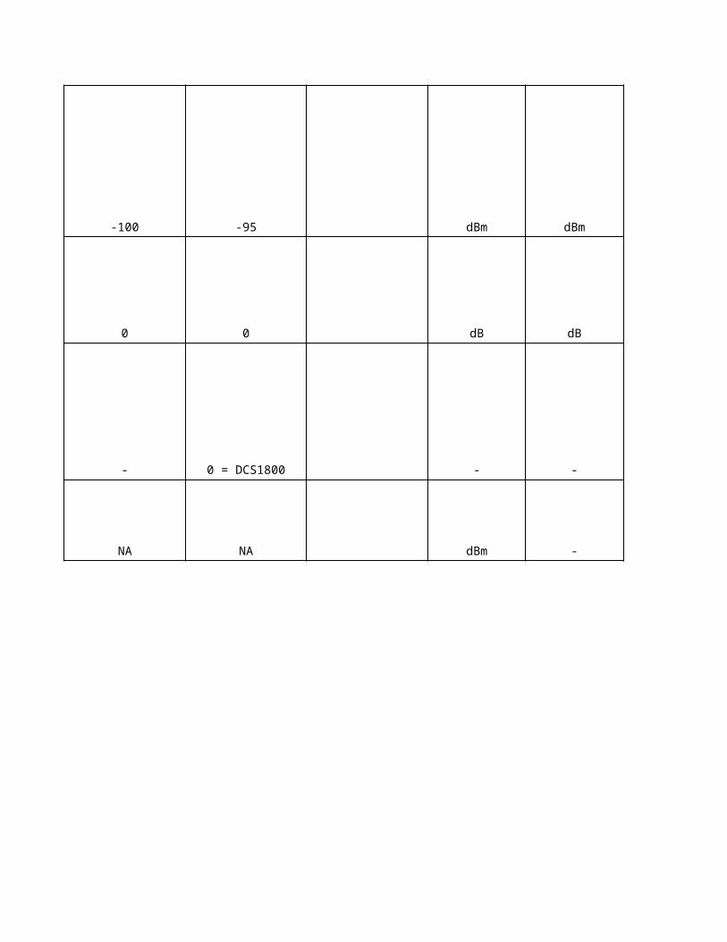
NA
NA
NA
NA
NA
NA
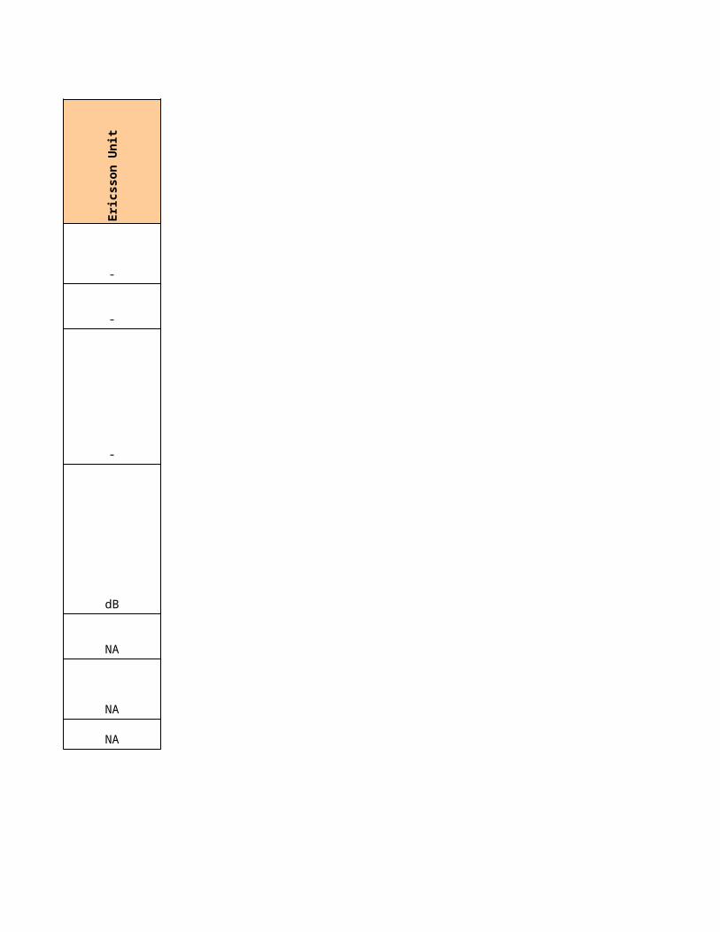
NA
NA
NA
NA
NA
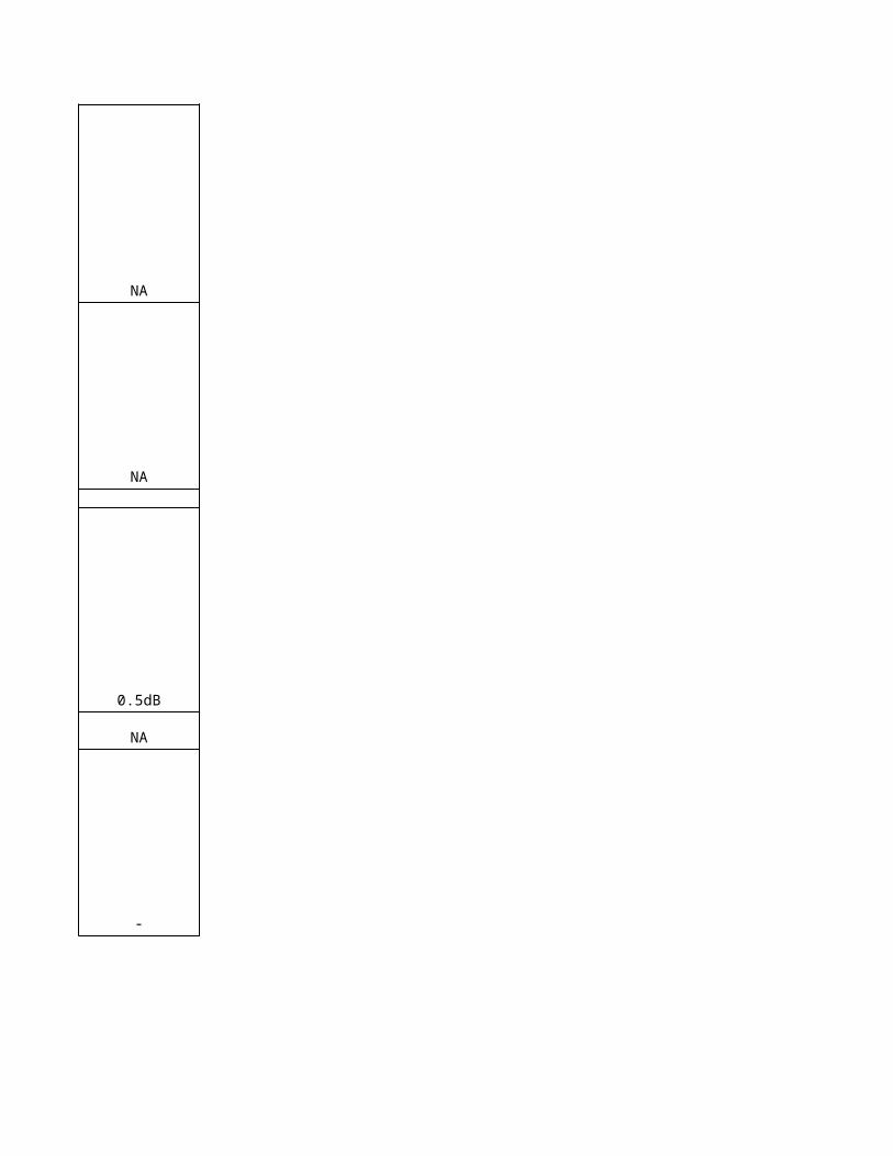
NA
NA
NA
NA
NA
This parameter indicates whether an inter-frequency handover caused by low measured absolute CPICH Ec/No of the serving cell is enabled. When the inter-frequency handover is enabled, the RNC shall set up an intra-frequency CPICH Ec/No measurement in order to monitor the absolute CPICH Ec/No of the serving cell. The measurement reporting criteria of the intra-frequency CPICH Ec/No measurement are defined by the Intra-frequency Measurement Control parameters (FMCS object).

This parameter indicates whether an inter-frequency handover caused by low measured absolute CPICH RSCP of the serving cell is enabled. When the inter-frequency handover is enabled, the RNC shall set up an intra-frequency CPICH RSCP measurement in order to monitor the absolute CPICH RSCP of the serving cell. The measurement reporting criteria of the intra-frequency CPICH RSCP measurement are defined by the Intra-frequency Measurement Control parameters (FMCS object).
If the inter-frequency or inter-RAT (GSM) handover caused by low measured absolute CPICH Ec/No is enabled, the RNC starts the inter-frequency or GSM measurement in compressed mode when all active set cells have triggered the reporting event 1F for CPICH Ec/No. The RNC cancels the event 1F of an active set cell if the CPICH Ec/No measurement result of the active set cell becomes better than or equal to the threshold HHoEcNoCancel and the UE transmits the corresponding event 1E triggered Measurement Report to the RNC. Note that once the RNC has started the inter-frequency or inter-RAT (GSM) measurement for the purpose of hard handover due to low measured absolute CPICH Ec/No, the RNC does not break off the ongoing measurement, even if one or more active set cells trigger the reporting event 1E for CPICH Ec/No.
If the inter-frequency or inter-RAT (GSM) handover caused by low measured absolute CPICH Ec/No is enabled, the RNC starts the inter-frequency or GSM measurement in compressed mode when all active set cells have triggered the reporting event 1F for CPICH Ec/No. The RNC cancels the event 1F of an active set cell if the CPICH Ec/No measurement result of the active set cell becomes better than or equal to the threshold HHoEcNoCancel and the UE transmits the corresponding event 1E triggered Measurement Report to the RNC. The parameter HHoEcNoCancelTime determines the time period during which the CPICH Ec/No of the active set cell must stay better than the threshold HHoEcNoCancel before the UE can trigger the reporting event 1E. Note that once the RNC has started the inter-frequency or inter-RAT (GSM) measurement for the purpose of hard handover due to low measured absolute CPICH Ec/No, the RNC does not break off the ongoing measurement, even if one or more active set cells trigger the reporting event 1E for CPICH Ec/No.
If the inter-frequency or inter-RAT (GSM) handover caused by low measured absolute CPICH Ec/No is enabled, the UE transmits an event 1F triggered measurement report to the RNC when the CPICH Ec/No measurement result of an active set cell becomes worse than or equal to an absolute CPICH Ec/No threshold.
The parameter HHoEcNoThreshold determines the absolute CPICH Ec/No threshold which is used by the UE to trigger the reporting event 1F. When the measured CPICH Ec/No of all active set cells has become worse than or equal to the threshold in question, the RNC starts inter-frequency or inter-RAT (GSM) measurements in compressed mode for the purpose of hard handover.
If the inter-frequency or inter-RAT (GSM) handover caused by low measured absolute CPICH Ec/No is enabled, the UE transmits an event 1F triggered measurement report to the RNC when the CPICH Ec/No measurement result of an active set cell becomes worse than the threshold HHoEcNoThreshold. The parameter HHoEcNoTimeHysteresis determines the time period during which the CPICH Ec/No of the active set cell must stay worse than the threshold HHoEcNoThreshold before the UE can trigger the reporting event 1F. When the measured CPICH Ec/No of all active set cells has become worse than the threshold in question, the RNC starts inter-frequency or inter-RAT (GSM) measurements in compressed mode for the purpose of hard handover.
If the inter-frequency or inter-RAT (GSM) handover caused by low measured absolute CPICH RSCP is enabled, the RNC starts the inter-frequency or GSM measurement in compressed mode when all active set cells have triggered the reporting event 1F for CPICH RSCP. The RNC cancels the event 1F of an active set cell, if the CPICH RSCP measurement result of the active set cell becomes better than or equal to the threshold HHoRscpCancel and the UE transmits the corresponding event 1E triggered measurement report to the RNC. Note, that once the RNC has started the inter-frequency or inter-RAT (GSM) measurement for the purpose of hard handover due to low measured absolute CPICH RSCP, the RNC does not break off the ongoing measurement, even if one or more active set cells trigger the reporting event 1E for CPICH RSCP.
No
kia
De
sc
rip
tio
n
If the inter-frequency or inter-RAT (GSM) handover caused by low measured absolute CPICH RSCP is enabled, the RNC starts the inter-frequency or GSM measurement in compressed mode when all active set cells have triggered the reporting event 1F for CPICH RSCP. The RNC cancels the event 1F of an active set cell, if the CPICH RSCP measurement result of the active set cell becomes better than or equal to the threshold HHoRscpCancel and the UE transmits the corresponding event 1E triggered measurement report to the RNC. The parameter HHoRscpCancelTime determines the time period during which the CPICH RSCP of the active set cell must stay better than the threshold HHoRscpCancel before the UE can trigger the reporting event 1E.Note, that once the RNC has started the inter-frequency or inter-RAT (GSM) measurement for the purpose of hard handover due to low measured absolute CPICH RSCP, the RNC does not break off the ongoing measurement, even if one or more active set cells trigger the reporting event 1E for CPICH RSCP.
If the inter-frequency or inter-RAT (GSM) handover caused by a low measured CPICH RSCP is enabled, the UE transmits an event 1F triggered measurement report to the RNC when the CPICH RSCP measurement result of an active set cell becomes worse than or equal to an absolute CPICH RSCP threshold. The parameter HHoRscpThreshold determines the absolute CPICH RSCP threshold which is used by the UE to trigger the reporting event 1F. When the measured CPICH RSCP of all active set cells has become worse than or equal to the threshold in question, the RNC starts inter-frequency or inter-RAT (GSM) measurements in compressed mode for the purpose of hard handover.
If the inter-frequency or inter-RAT (GSM) handover caused by low measured CPICH RSCP is enabled, the UE transmits an event 1F triggered measurement report to the RNC when the CPICH RSCP measurement result of an active set cell becomes worse than the threshold HHoRscpThreshold. The parameter HHoRscpTimeHysteresis determines the time period during which the CPICH RSCP of the active set cell must stay worse than the threshold HHoRscpThreshold before the UE can trigger the reporting event 1F. When the measured CPICH RSCP of all active set cells has become worse than the threshold in question, the RNC starts inter-frequency or inter-RAT (GSM) measurements in compressed mode for the purpose of hard handover.
This parameter determines the minimum required CPICH RSCP level which the averaged measurement result of the best inter-frequency neighbour cell must exceed before the quality reason inter-frequency handover is possible.
This parameter indicates the maximum transmission power level that a UE may use on the DPCH in the neighbouring cell. The RNC uses the parameter in the decision algorithm of the inter-frequency handover. If the maximum output power of the UE is lower than the value of the parameter, the RNC adds the power difference (dB value) to the minimum required CPICH RSCP level, which the measurement result of the neighbour cell must exceed before the handover is possible.
This parameter determines the margin by which the averaged CPICH Ec/No measurement result of the best inter-frequency neighbour cell must exceed the averaged CPICH Ec/No measurement result of the best active set cell before the quality reason inter-frequency handover is possible.
This parameter determines the minimum required CPICH Ec/No level which the averaged measurement result of the best inter-frequency neighbour cell must exceed before the coverage reason inter-frequency handover is possible.
This parameter determines the margin by which the averaged propagation loss of the best active set cell must exceed the averaged propagation loss of the best inter-frequency neighbour cell before the coverage reason inter-frequency handover is possible.
NA
NA
NANANA
NA
NANANA
NA
NA
NANA
NA
NA
NA
NANA
NANA
NA
The parameter indicates whether the GSM neighbour cell is included in the System Information Block 11&12&18 for the cell selection and re-selection procedures. The GSM neighbour cell is included in the system information when the value of the parameter is "yes". If the Wireless Priority Service feature is enabled, then parameter Include in System Information shall be set to have value "yes" for ADJG-0. If the total number of intra-frequency, inter-frequency and GSM neighbour cells, which are included in the System Information, exceeds the physical size of SIB data, the NBAP interface is not able to pack the neighbour cell information into the SIB data and the scheduling of the system information blocks fails. The cell is blocked by the system and an alarm 7771 WCDMA CELL OUT OF USE (BCCH scheduling error) is reported for the cell. Note: The parameter AdjgSIB does not affect GSM measurements in CELL_DCH state of connected mode. That is, all GSM neighbour cells are monitored for the inter-system handover regardless of the value of the parameter AdjgSIB.
Determines the minimum required RSSI level which the measurement result of the GSM neighbour cell must exceed before the cell re-selection becomes possible.
This parameter indicates how to interpret the value of the parameter AdjgBCCH.
This parameter is used in the cell re-selection and ranking between WCDMA and GSM cells. The value of this parameter is subtracted from the measured GSM carrier RSSI of the neighbouring cell before the UE compares the quality measure with the cell re-selection/ranking criteria.
This parameter determines the minimum required GSM RSSI level which the averaged RSSI value of the GSM neighbour cell must exceed before the coverage (or quality) reason handover to GSM is possible.
This parameter determines the minimum required GSM RSSI level which the averaged RSSI value of the GSM neighbour cell must exceed before the coverage (or quality) reason handover to GSM is possible.
This parameter indicates the maximum transmission power level that an UE may use on a TCH in the GSM neighbour cell. The RNC uses the parameter in the decision algorithm of the inter-RAT (GSM) handover. If the maximum output power of the UE is lower than the value of the parameter, the RNC adds the power difference (dB value) to the minimum required GSM RSSI level, which the measurement result of the GSM neighbour cell must exceed before the handover is possible.
Sie
me
ns
De
sc
rip
tio
n
Default value is 0.
Pathloss = Primary CPICH Tx power - CPICH RSCP
Active Set Size; 1 shall not be used
Used to offset measured quantity value
Used to offset measured quantity value
-
-
Threshold for soft/softer handover
Hysteresis value for branch addition in soft/softer handover
Configures the adjacency as relevant for:-Selection and Reselection:Idle mode and FACH-connected mode (System Information Update SIB 11);-Handover:DCH- connected mode (RRC Measurement Control message);-Both: combination of Selection/ Reselection and Handover
Configures the adjacency as relevant for:-Selection and Reselection:Idle mode and FACH-connected mode (System Information Update SIB 11);-Handover:DCH- connected mode (RRC Measurement Control message);-Both: combination of Selection/ Reselection and Handover
Gives the offset between Reporting Range of event 1A and event 1A‘ (improved soft handover failure)., if CR682 (optional patch) is applied.
Weighting FactorWith increased weighting factor the quality from the active set will has a larger impact on triggering decisions.Recommendation: Replace Default by optimized value
Amount of reporting.
Threshold for soft/softer handover
Indicates the period of time between the timing of event detection and the timing of sending Measurement Report.Recommendation: Replace Default by optimized value
Period of UE intra frequency measurements Value 0 means no periodical reporting.Recommendation: Replace Default by optimized value
Weighting FactorWith increased weighting factor the quality from the active set will has a larger impact on triggering decisions.Recommendation: Replace Default by optimized value
Hysteresis value for branch deletion in soft/softer handover
Hysteresis value for branch replacement
Indicates the period of time between the timing of event detection and the timing of sending Measurement Report.
Amount of reporting.
Hysteresis for branch replacement
NA
Indicates the period of time between the timing of event detection and the timing of sending Measurement Report.Recommendation: Replace Default by optimized value
Period of UE intra frequency measurements Value 0 means no periodical reporting.Recommendation: Replace Default by optimized value
NA
Sie
me
ns
De
sc
rip
tio
n
Default value is 0.
Indicates the period of time between the timing of event detection and the timing of sending Measurement Report.
Measurement quantity for frequency quality estimate
Weighting FactorThis parameter is invalid, but please input some values within the range.
Determines the hysteresis valueThis parameter value must be smaller than ‘hyst_2ad’This parameter is invalid, but please input some values within the range
Indicates the period of time between the timing of event detection and the timing of sending Measurement Report.This parameter is invalid, but please input some values within the range.
Weighting Factor for the non used frequencyThis parameter is invalid, but please input some values within the range
Weighting Factor for the used frequency; Used for event 2A.Determines the hysteresis value; Used for event 2A
Weighting Factor for the non used frequency; Used for event 2A.
NA
Determines the hysteresis value.
Indicates the period of time between the timing of event detection and the timing of sending Measurement Report. Used for event 2A
Determines the threshold value for the used frequencyThreshold/range depends on selection of Measurement Quantity.
Weighting Factor for the used frequencyRecommendation: Replace Default by optimized value
Indicates the period of time between the timing of event detection and the timing of sending Measurement Report.
Determines the threshold value for the non-used frequencyThreshold/range depends on selection of Measurement Quantity.
NA
NA
NA
NA
Weighting Factor for the non used frequencyRecommendation: Replace Default by optimized value
Ranges used depend on measurement quantity.CPICH Ec/No –24,...,0 dBCPICH RSCP –115,...,-25 dBm.
Weighting Factor.
Determines the hysteresis value
NA
Indicates the period of time between the timing of event detection and the timing of sending Measurement Report.Recommendation: Replace Default by optimized value
Determines the threshold value for the non-used frequencyThreshold/range depends on selection of Measurement Quantity.
NA
Weighting Factor.
NA
-
Determines the hysteresis value
Indicates the period of time between the timing of event detection and the timing of sending Measurement Report.
-
-
-
-
-
-
-
-
-
-
-
-
-
-
Sie
me
ns
De
sc
rip
tio
n
Measurement quantity for frequency quality estimate
Default value is 0.
Weighting Factor; Determines the hysteresis value;
Weighting Factor. Determines the hysteresis value
Required means that UE has to verify the BSIC in the measured GSM cell
Ranges used depend on measurement quantity.CPICH Ec/No –24,...,0 dBCPICH RSCP –115,...,-25 dBm;
Indicates the period of time between the timing of event detection and the timing of sending Measurement Report. Recommendation: Replace Default by optimized value
Determines the threshold value for the non-used frequencyThreshold/range depends on selection of Measurement Quantity.
Indicates the period of time between the timing of event detection and the timing of sending Measurement Report.
Filter Coefficient to be applied (event 3A)Recommendation: Replace Default by optimized value
Filter Coefficient to be applied (event 3A); Must be set to RSCP if combined measurements shall be applicable.Recommendation: Replace Default by optimized value
Determines the threshold value; Must be set to a value >= -24 if combined measurements shall be applicable. Value is used for “own system” 3a’ (Ec/N0) “Threshold other system” 3a’ is set to -100dBm. Recommendation: Replace Default by optimized value
NA
Controls the UE measurment behaviour to be applied initially in target GPRS cell
Physical quantity to be measured by the UE (event 3A)Physical quantity to be measured by the UE (event 3A)
Weighting Factor Recommendation: Replace Default by optimized value
Indicates the period of time between the timing of event detection and the timing of sending Measurement Report.Recommendation: Replace Default by optimized value
This parameter enables/disables inter-system measurements and RRC Cell Change Order from UTRAN procedure in CELL_DCH state with PS RAB(s) only
Used to offset measured quantity value
Specifies the minimum required RX level in the neighbour cell
Configures the adjacency as relevant for:-Selection and Reselection:Idle mode and FACH-connected mode (System Information Update SIB 11);-Handover:DCH- connected mode (RRC Measurement Control message);-Both: combination of Selection/ Reselection and Handover
Determines the hysteresis value
Indicates how to interpret the BCCH ARFCN
NA
This specifies the offset between the two cells in case the quality measure for cell selection and re-selection is set to CPICH RSCP.
Determines the threshold value; Must be set to a value >= -24 if combined measurements shall be applicable. Value is used for “own system” 3a’ (Ec/N0) “Threshold other system” 3a’ is set to -100dBm. Recommendation: Replace Default by optimized
Eri
cs
so
n D
es
cri
pti
on
NA
NA
NA
Coefficient for layer 3 filtering before intra-frequency reporting evaluation.
Unit: N/AResolution: 1
Used by UE functions for intra-frequency measurements (in CELL_DCH). Quantity to measure for the chosen mode. The value of this attribute will set the message data CPICH_Ec/No or CPICH_RSCP accordingly.
Maximum number of cells in active set.
This attribute also controls the reporting deactivation threshold, used to control intra-frequency measurements (event 1a).reporting deactivation threshold = maxActiveSet-1.
The attribute also controls the replacement activation threshold, used to control intra-frequency measurements (event 1c).replacement activation threshold = maxActiveSet.
Used in UE function event-reporting. This offset is added to the measured quantity before the UE evaluates if an event has occured.
Unit: 0.1 dBResolution: 5
-100: -10,0 dB- 95: - 9,5 dB... 100: 10,0 dB
NA
NA
NA
Used by UE functions for intra-frequency measurement reporting (in CELL_DCH). Threshold used for addition-window in evaluation criteria for event type 1a.
Resolution: 1 (=0.5db)
0: 0.0dB1: 0.5dB...6: 3.0db..29: 14.5dB
Weight factor to include active set cells other than the best in evaluation criteria for event 1a.Used by UE functions for intra-frequency measurement reporting (in CELL_DCH).
Unit: 0.1Resolution: 1
0 : 0.01 : 0.1...20 : 2.0
Hysteresis used in addition-window in evaluation criteria for event 1a to avoid ping pong effects. Used by UE functions for intra-frequency measurement reporting in CELL_DCH.
Unit: 0.5 dBResolution: 1
0 : 0.0dB (no hysteresis)1 : 0.5dB...15 : 7.5dB

NA
Time in milliseconds (ms) between detection of event 1a and sending of the measurement report.
Used by UE functions for intra-frequency measurement reporting in CELL_DCH.
Unit: N/AResolution: N/A
0 : 0 ms1 : 10 ms2 : 20 ms3 : 40 ms4 : 60 ms5 : 80 ms6 : 100 ms7 : 120 ms8 : 160 ms9 : 200 ms10 : 240 ms11 : 320 ms12 : 640 ms13 : 1280 ms14 : 2560 ms15 : 5000 ms
Interval of event-triggered periodical reporting in case of 'cell addition failure' or 'cell replacement failure'. Indicates the interval in seconds (s) of periodical reporting triggered by event 1a. Used by UE functions for intra-frequency measurement reporting in CELL_DCH.
0 : No event-triggered periodical reporting1 : 0.25 s2 : 0.5 s3 : 1 s4 : 2 s5 : 4 s6 : 8 s7 : 16 s
Used by UE functions for intra-frequency measurement reporting (in CELL_DCH). Threshold used for dropwindow in evaluation criteria for event 1b.
Resolution: 1 (=0.5db)
0: 0.0dB1: 0.5dB
Weight factor to include active set cells other than the best in evaluation criteria for event 1b.Used by UE functions for intra-frequency measurement reporting (in CELL_DCH).
Unit: 0.1Resolution: 1
0 : 0.01 : 0.1...20 : 2.0

Hysteresis used in the drop window in evaluation criteria for event type 1b. Used by UE functions for intra-frequency measurement reporting in CELL_DCH.
Unit: 0.5 dBResolution: 1
0 : 0.0dB (no hysteresis)1 : 0.5dB...15 : 7.5dB
Time in milliseconds (ms) between detection of event 1b and sending of the measurement report.
Used by UE functions for intra-frequency measurement reporting in CELL_DCH.
Unit: N/AResolution: N/A
0 : 0 ms1 : 10 ms2 : 20 ms3 : 40 ms4 : 60 ms5 : 80 ms6 : 100 ms7 : 120 ms8 : 160 ms9 : 200 ms10 : 240 ms11 : 320 ms12 : 640 ms13 : 1280 ms14 : 2560 ms15 : 5000 ms
Used by UE functions for intra-frequency measurement reporting (in CELL_DCH). Hysteresis used in replacement threshold in evaluation criteria for event 1c to avoid ping pong effects.
Resolution: 1: (=0.5 dB)
0: 0.0dB (no hystersis)1: 0.5dB2: 1.0dB..15: 7.5dB

NA
Time in milliseconds (ms) between detection of event 1c and sending of the measurement report.
Used by UE functions for intra-frequency measurement reporting in CELL_DCH.
Unit: N/AResolution: N/A
0 : 0 ms1 : 10 ms2 : 20 ms3 : 40 ms4 : 60 ms5 : 80 ms6 : 100 ms7 : 120 ms8 : 160 ms9 : 200 ms10 : 240 ms11 : 320 ms12 : 640 ms13 : 1280 ms14 : 2560 ms15 : 5000 ms
Interval of event-triggered periodical reporting in case of 'cell addition failure' or 'cell replacement failure'. Indicates the interval in seconds (s) of periodical reporting triggered by event 1c. Used by UE functions for intra-frequency measurement reporting in CELL_DCH.
0 : No event-triggered periodical reporting1 : 0.25 s2 : 0.5 s3 : 1 s4 : 2 s5 : 4 s6 : 8 s7 : 16 s
Used by UE functions for intra-frequency measurement reporting (in CELL_DCH). Hysteresis used in dropwindow in evaluation criteria for event type 1d.
Unit: 0.5 dBResolution: 1
0: 0.0dB (no hysteresis)1: 0.5dB2: 1.0dB..15: 7.5dB
Sets the Event 1D hysteresis value specific for HS connections
Unit: 0.1 dBResolution: 5
Eri
cs
so
n D
es
cri
pti
on
NA
NA
NA
NA
NA
Time in milliseconds (ms) between detection of event 1d and sending of the measurement report.
Unit: N/AResolution: N/A
0 : 0 ms1 : 10 ms2 : 20 ms3 : 40 ms4 : 60 ms5 : 80 ms6 : 100 ms7 : 120 ms8 : 160 ms9 : 200 ms10 : 240 ms11 : 320 ms12 : 640 ms13 : 1280 ms14 : 2560 ms15 : 5000 ms
Sets the Event 1D Time to Trigger value specific for HS connections
Unit: 1 ms.Resolution: N/A
Coefficient for layer 3 filtering before inter-frequency measurement reporting evaluation.
Unit: N/AResolution: 1
NANA
NANA
Relative threshold for event 2b vs event 2d, when the 2d measurement with measurement quantity CPICH EC/NO was started.
This parameter is used to compute the absolute 2b Ec/No used frequency threshold, by adding it to the current 2d Ec/No threshold (absolute 2b Ec/No used frequency threshold = usedFreqThresh2dEcno + usedFreqRelThresh4_2bEcno).
If the sum of the calculation exceeds the maximum 3GPP value, the absolute 2b Ec/No threshold value will be adjusted to the maximum value allowed by 3GPP before a Measurement Control message is encoded and sent to the UE.
Note: This attribute replaces usedFreqThresh4_2bEcno.
Unit: 1 dBResolution: 1
Relative threshold for event 2b vs event 2d when the 2d measurement with measurement quantity CPICH RSCP was started.
This parameter is used to compute the absolute 2b Rscp threshold, by adding it to the current 2d Rscp threshold (absolute 2b Rscp used frequency threshold = usedFreqThresh2dRscp + usedFreqRelThresh4_2bRscp).
If the sum of the calculation exceeds the maximum 3GPP value, the absolute 2b Rscp threshold value will be adjusted to the maximum value allowed by 3GPP before a Measurement Control message is encoded and sent to the UE.
Note: This attribute replaces usedFreqThresh4_2bRscp.
Unit: 1 dBResolution: 1
Weighting factor for measurement 4 event 2b for the currently used frequency.
Unit: 0.1Resolution: 1
Hysteresis for measurement 4 event 2b.
Unit: 0.1 dBResolution: 5
Time between detection of event 2b and sending of the measurement report, for measurement 4.
Unit: 1 msResolution: N/A
Threshold for measurement 4 event 2b for the non-used frequencies when the measurement quantity is Ec/No.
Unit: 1 dBResolution: 1
Threshold for measurement 4 event 2b for the non-used frequencies when the measurement quantity is RSCP.
Unit: 1 dBmResolution: 1
Weighting factor for measurement 4 event 2b for the non-used frequencies.
Unit: 0.1Resolution: 1
Threshold for event 2d for the used frequency when the measurement quantity is Ec/No.
Note: This parameter is also used for calculation of a threshold value for the used frequency for 2f events. The calculated value is sent to the UE in a RRC Measurement Control message. If the sum of the calculation (usedFreqRelThresh2fEcno + usedFreqThresh2dEcno) exceeds the maximum 3GPP value 0dB, the value sent to the UE will be 0dB.
Unit: 1 dBResolution: 1
Threshold for event 2d for the used frequency when the measurement quantity is RSCP.
Note: This parameter is also used for calculation of a threshold value for the used frequency for 2f events. The calculated value is sent to the UE in a RRC Measurement Control message. If the sum of the calculation (usedFreqRelThresh2fRscp + usedFreqThresh2dRscp) exceeds the maximum 3GPP value -25dBm, the value sent to the UE will be -25dBm.
Unit: 1 dBmResolution: 1
Threshold for event 2d for the used frequency for cells located in DRNC when the measurement quantity is Ec/No.
Note: This parameter is also used for calculation of a threshold value for the used frequency for 2f events. The calculated value is sent to the UE in a RRC Measurement Control message. If the sum of the calculation (usedFreqRelThresh2fEcno + usedFreqThresh2dEcnoDrnc) exceeds the maximum 3GPP value 0dB, the value sent to the UE will be 0dB.
Unit: 1dBResolution: 1
Threshold for event 2d for the used frequency for cells located in the DRNC when the measurement quantity is RSCP.
Note: This parameter is also used for calculation of a a threshold value for the used frequency for 2f events. The calculated value is sent to the UE in a RRC Measurement Control message. If the sum of the calculation (usedFreqRelThresh2fRscp + usedFreqThresh2dRscpDrnc) exceeds the maximum 3GPP value -25dBm, the value sent to the UE will be -25dBm.
Unit: 1dBmResolution: 1

Weighting factor for event 2d for the used frequency.
Unit: 0.1Resolution: 1
0 : 0.01 : 0.12 : 0.2.....20 : 2.0
Hysteresis for event 2d.
Resolution: 1 (=0.5db)
0: 0.0dB1: 0.5dB..29: 14.5dB
Time in milliseconds (ms) between detection of event 2d and sending of the measurement report, when the measurement quantity is CPICH EC/NO.
When the value 5000 is set, the measurement report will not be sent at all.
Unit: 1 msResolution: N/A
Time in milliseconds (ms) between detection of event 2d and sending of the measurement report, when the measurement quantity is CPICH RSCP.
When the value 5000 is set, the measurement report will not be sent at all.
Unit: 1 msResolution: N/A
Relative threshold for event 2f vs event 2d for the used frequency when the measurement quantity is Ec/No.
Note 1: The threshold for event 2d is configured per cell in usedFreqThresh2dEcno. For DRNC cells, the global value usedFreqThresh2dEcnoDrnc is used instead.
Note 2: This parameter is used for calculation of a threshold value for the used frequency for 2f events. The calculated value is sent to the UE in a RRC Measurement Control message. If the sum of the calculation (usedFreqRelThresh2fEcno + usedFreqThresh2dEcno), or (usedFreqRelThresh2fEcno + usedFreqThresh2dEcnoDrnc) for DRNC cells, exceeds the maximum 3GPP value 0dB, the value sent to the UE will be 0dB.
Unit: 1dBResolution: 1
NA
Relative threshold for event 2f vs event 2d for the used frequency when the measurement quantity is RSCP.
Note 1: the threshold for event 2d is configured per cell in usedFreqThresh2dRscp. For DRNC cells, the global value usedFreqThresh2dRscpDrnc is used instead.
Note 2: This parameter is used for calculation of a threshold value for the used frequency for 2f events. The calculated value is sent to the UE in a RRC Measurement Control message. If the sum of the calculation (usedFreqRelThresh2fRscp + usedFreqThresh2dRscp), or (usedFreqRelThresh2fRscp + usedFreqThresh2dRscpDrnc) for DRNC cells, exceeds the maximum 3GPP value -25dBm, the value sent to the UE will be -25dBm.
Unit: 1dBResolution: 1
Weighting factor for event 2f for the used frequency.
Unit: 0.1Resolution: 1
0 : 0.01 : 0.12 : 0.2.....10 : 1.011 : 1.1.....20 : 2.0
Hysteresis for event 2f.
Resolution: 1 (=0.5db)
0: 0.0dB1: 0.5dB..29: 14.5dB
Time in milliseconds (ms) between detection of event 2f and sending of the measurement report, when the measurement quantity is CPICH EC/NO.
Unit: 1 msResolution: N/A
Time in milliseconds (ms) between detection of event 2f and sending of the measurement report, when the measurement quantity is CPICH RSCP.
Unit: 1 msResolution: N/A
NA
NA
NA
NA
NA
NA
NA
NA
NA
NA
NA
NA
NA
NA
Eri
cs
so
n D
es
cri
pti
on
NA
NANANA
NA
NANANA
NA
NA
NA
Coefficient for layer 3 filtering of UTRAN quality before inter-RAT reporting evaluation.
Unit: N/AResolution: 1
Coefficient for layer 3 filtering of GSM quality before inter-RAT reporting evaluation.
Unit: N/AResolution: 1
Relative threshold for event 3a vs event 2d, when the 2d measurement with measurement quantity CPICH EC/NO was started.
This parameter is used to compute the absolute 3a Ec/No threshold, by adding it to the current 2d Ec/No threshold (absolute 3a Ec/No threshold = usedFreqThresh2dEcno + utranRelThresh3aEcno).
If the sum of the calculation exceeds the maximum 3GPP value, the absolute 3a Ec/No threshold value will be adjusted to the maximum value allowed by 3GPP before a Measurement Control message is encoded and sent to the UE.
Note: This attribute replaces utranThresh3aEcno.
Unit: 1 dBResolution: 1
NA
NANANA
Relative threshold for event 3a vs event 2d when the 2d measurement with measurement quantity CPICH RSCP was started.
This parameter is used to compute the absolute 3a Rscp threshold, by adding it to the current 2d Rscp threshold (absolute 3a RSCP threshold = usedFreqThresh2dRscp + utranRelThresh3aRscp).
If the sum of the calculation exceeds the maximum 3GPP value, the absolute 3a RSCP threshold value will be adjusted to the maximum value allowed by 3GPP before a Measurement Control message is encoded and sent to the UE.
Note: This attribute replaces utranThresh3aRscp.
Unit: 1 dBResolution: 1
Weighting factor for event 3a for UTRAN.
Unit: 0.1Resolution: 1
0 : 0.01 : 0.12 : 0.2.....20 : 2.0
Time in milliseconds (ms) between detection of event 3a and sending of the measurement report.
Unit: N/AResolution: N/A
0 : 0 ms1 : 10 ms2 : 20 ms3 : 40 ms4 : 60 ms5 : 80 ms6 : 100 ms7 : 120 ms8 : 160 ms9 : 200 ms10 : 240 ms11 : 320 ms12 : 640 ms13 : 1280 ms14 : 2560 ms15 : 5000 ms
NA
Used in UE function event-reporting. This offset is added to the measured quantity before the UE evaluates if an event has occured.
The parameter is used both for signalling over RRC and RNSAP.
Unit: 1 dBResolution: 1
-50: -50 dB...0: 0 dB...50: 50 dB
Used in UE functions for cell selection/reselection in idle mode and connected mode. Minimum required (acceptable) RX level in the cell. (dBm). Value launched by System information (SIB11) for each intra-frequency measurement object corresponding to adjacent cells of serving cell.
Unit: 1 dBmResolution: 2
-115 : -115dBm-113 : -113dBm-111 : -111dBm-109 : -109dBm.....
-25 : -25 dBm
100 : Indicates that the minimum Rx level has not been specified by the operator. The parameter is then notpresent in SIB11 for this neighbour. The UE will use the serving cell value (UtranCell MO value) instead.
NA
Signal stength offset between source and target cells. Used when the IE "cell_selection_and_reselection_quality_measure" in SIB 11/12 is set to "CPICH RSCP". This is configured through UtranCell::qualMeasQuantity.
Unit: 1 dBResolution: 1
-50 : -50dB-49 : -49dB-48 : -48dB......50 : 50dB
Threshold for event 3a for GSM. Range is valid for GSM carrier RSSI.
Resolution is 1 (=1 dBm).
-115 : -115 dBm-114 : -114 dBm..-104 : -104 dBm..0 : 0 dBm
Hysteresis for event 3a.
Resolution 1: (0.5dB).
0: 0.0dB...15: 7.5dB
Indicates the frequency band of the external GSM cell.
The BCCH frequency is unique for all GSM bands except the two GSM bands DCS1800 and PCS1900, so the band indicator is needed to discriminate between the two. When the ExternalGsmCell has a BCCH frequency indicating some other frequency band, then the band indicator is not needed and may be set to "Not applicable".
Unit: N/AResolution: N/A