Embed Size (px)
Citation preview
PARAMETER IDENTIFICATION OF A COUPLED TANK LIQUID
LEVEL SYSTEM VIA PARTICLE SWARM OPTIMIZATION
NUR AZMINA BT OTHMAN
This thesis is submitted as partial fulfillment of the requirements for the award of the
Bachelor of Electrical Engineering (Hons.) (Control & Instrumentation)
Faculty of Electric & Electronics
Universiti Malaysia Pahang
NOVEMBER 2009

SUPERVISOR’S DECLARATION
“I hereby acknowledge that the scope and quality of this thesis is qualified for the award
of the Bachelor of Electrical Engineering (Control & Instrumentation)”
Signature : ______________________________________________
Name : MOHD. SYAKIRIN BIN RAMLI
Date : 24 th
NOVEMBER 2009

STUDENT’S DECLARATION
“All the trademark and copyrights use herein are property of their respective owner.
References of information from other sources are quoted accordingly; otherwise the
information presented in this report is solely work of the author.”
Signature : ____________________________
Author : NUR AZMINA BT OTHMAN
Date : 24 th
NOVEMBER 2009

i
ACKNOWLEDGEMENTS
In the name of Allah S.W.T, the Most Gracious, the Ever Merciful. Praise is to
Allah, Lord of the Universe and Peace and Prayers be upon His final Prophet and
Messenger Muhammad s.a.w. Thank you for giving me the source of power, guidance in
applying knowledge and strength to finish the project and dissertation for completing my
Bachelor of Electrical Engineering final year project.
I would like to express my gratitude to my supervisor Mr. Mohd Syakirin bin
Ramli for his wisdom, endurance and encouragement during his supervision period. His
high motivated spirit and hardworking in every work he do is admirable, and I have
always been encouraged to do better in my project and also in living a life.
I also would like to express my appreciation to all lab technicians especially to
Mr. Hamka for their help and permission to use lab and equipment needed throughout
this project completion.
Special thank to my friends for their kindness in getting and sharing additional
information for the project as well as their co-operation and help.
Finally, special thanks extended to my beloved family especially my father, Mr
Othman b Zainol and my mother, Mrs Hayani bt Abd Hamid, also brothers for their
never ending moral support, financial support and prays for my success.
ii
ABSTRACT
This project focuses on obtaining a mathematical equation for a coupled tank
liquid level system. The aim of this project is to identify and obtain the mathematical
modeling utilizing Particle Swarm Optimization (PSO). The level of water in each tank
is monitored by a capacitive-type probe. Signal conditioning circuits convert the
measured capacitance (a function of the water level) to electrical signals in the range 0 to
+5 Volt DC. Output from simulated and modeling performance are compared until n set
number of iteration for error less output. The fitness function which equal to the sum of
errors less square over number of iteration is later used in Visual Basic. Using Visual
Basic, a GUI is developed to analyze and display both performances in terms of graph.
In addition, both performances are also analyzed in terms of its transient and steady-state
responses. The obtained mathematical equation can further be used for controller
development such as by simulation in MATLAB/Simulink
iii
ABSTRAK
Projek ini tertumpu pada mendapatkan persamaan matematik untuk tahap cair
tangki ditambah sistem. Objektif dari projek ini adalah untuk mengenalpasti dan
mendapatkan model matematik memanfaatkan Particle Swarm Optimization (PSO).
Paras air di masing-masing tangki dipantau oleh probe taip kapasitif. Litar
pengkondisian isyarat menukar Kapasitans terukur (fungsi dari peringkat air) kepada
isyarat-isyarat elektrik pada kisaran 0-5 Volt DC. Output daripada simulasi dan
pemodelan prestasi berbanding sampai n jumlah iterasi menetapkan untuk kesalahan
kurang output. Kebugaran fungsi yang sama dengan jumlah kuadrat kesalahan kurang
lebih jumlah iterasi yang kemudian digunakan dalam Visual Basic. Menggunakan
Visual Basic, GUI yang dibangunkan untuk menganalisis dan memaparkan
persembahan, baik dalam hal grafik. Selain itu, kedua persembahan juga dianalisis dari
segi transien dan tanggapan keadaan tunak. Persamaan matematik yang diperolehi
selanjutnya dapat digunakan untuk pengembangan controller seperti dengan simulasi di
MATLAB / Simulink
iv
TABLE OF CONTENTS
CHAPTER TITLE PAGE
ACKNOWLEDGEMENT i
ABSTRACT ii
ABSTRAK iii
TABLE OF CONTENTS iv
LIST OF TABLES viii
LIST OF FIGURES ix
LIST OF ABBREVIATIONS xi
1 INTRODUCTION 1
1.1 Introduction 1
1.1.1 Coupled Tank Water Level System 1
1.1.2 Parameter Identification 2
1.1.3 Particle Swarm Optimization 2
1.2 Problem Statement 3
1.2.1 Coupled Tank Liquid Level System 3
1.2.2 Programmable Logic Controller 4
1.2.3 Parameter Identification 4
1.3 Objectives 4
1.4 Scope of Project 4
v
2 LITERATURE REVIEW 6
2.1 Introduction 6
2.2 Coupled Tank Water Level System 6
2.2.1 Coupled Tank Water Level System Application 7
2.3 Parameter Identification 7
2.3.1 Parameter Identification Application 7
2.4 Particle Swarm Optimization 8
2.5 Programmable Logic Controller 9
2.5.1 PLC Application 9
2.6 Matlab Simulink 10
2.7 Graphical User Interface (GUI) 10
3 METHODOLOGY 11
3.1 Introduction 11
3.2 Phase I Project Preview 12
3.2.1 Optimization Algorithm of Coupled Tank Water 13
Level System
3.3 Phase II Data Collection 13
3.3.1 Power Consumption 15
3.3.2 PLC CJ1M Setting 16
3.3.3 Analog Input and Analog Output Setting 19
3.3.4 Analog Output Card 19
3.3.5 Analog Input Card 22
3.3.6 Coupled Tank Water Level System 24
3.4 Phase III Modeling Equation of Coupled Tank 25
vi
3.5 Phase IV Data Simulation 28
3.5.1 Parameter Identification 30
3.5.2 Particle Swarm Optimization 30
3.5.3 Particle Swarm Optimization Pseudocode 32
3.5.4 Particle Swarm Optimization with GUI 32
Visual Basic
4 RESULTS AND ANALYSIS 35
4.1 Introduction 35
4.2 Project Result 35
4.3 Simulation Result 38
4.3.1 Particle Swarm Optimization in MATLAB 41
Simulink
5 CONCLUSION AND RECOMMENDATION 47
5.1 Introduction 47
5.2 Recommendations 48
5.2.1 Recommendation in Technique 48
5.2.2 Recommendation in Hardware improvement 48
5.2.3 Recommendation in Approach 49
5.3 Costing and Commercialization 49

vii
REFERENCES 50 61
APPENDICES 51
APPENDIX A - PARTICLE SWARM OPTIMIZATION
MATLAB CODING
APPENDIX B - GUI DATA COLLECTION CODING 59
viii
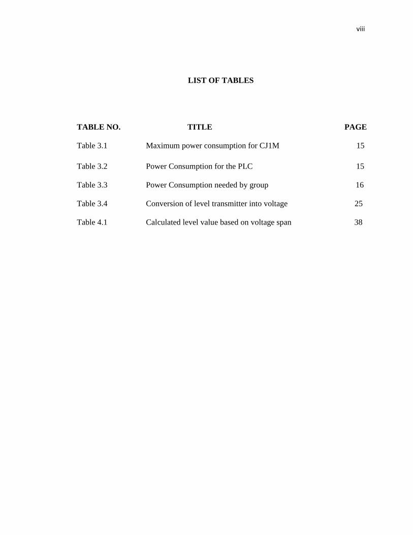
LIST OF TABLES
TABLE NO. TITLE PAGE
Table 3.1 Maximum power consumption for CJ1M 15
Table 3.2 Power Consumption for the PLC 15
Table 3.3 Power Consumption needed by group 16
Table 3.4 Conversion of level transmitter into voltage 25
Table 4.1 Calculated level value based on voltage span 38
ix
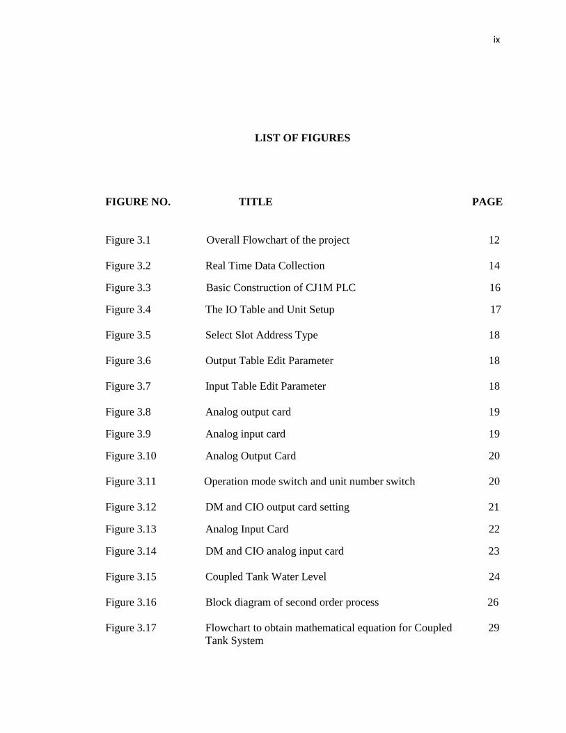
LIST OF FIGURES
FIGURE NO. TITLE PAGE
Figure 3.1 Overall Flowchart of the project 12
Figure 3.2 Real Time Data Collection 14
Figure 3.3 Basic Construction of CJ1M PLC 16
Figure 3.4 The IO Table and Unit Setup 17
Figure 3.5 Select Slot Address Type 18
Figure 3.6 Output Table Edit Parameter 18
Figure 3.7 Input Table Edit Parameter 18
Figure 3.8 Analog output card 19
Figure 3.9 Analog input card 19
Figure 3.10 Analog Output Card 20
Figure 3.11 Operation mode switch and unit number switch 20
Figure 3.12 DM and CIO output card setting 21
Figure 3.13 Analog Input Card 22
Figure 3.14 DM and CIO analog input card 23
Figure 3.15 Coupled Tank Water Level 24
Figure 3.16 Block diagram of second order process 26
Figure 3.17 Flowchart to obtain mathematical equation for Coupled 29
Tank System
x
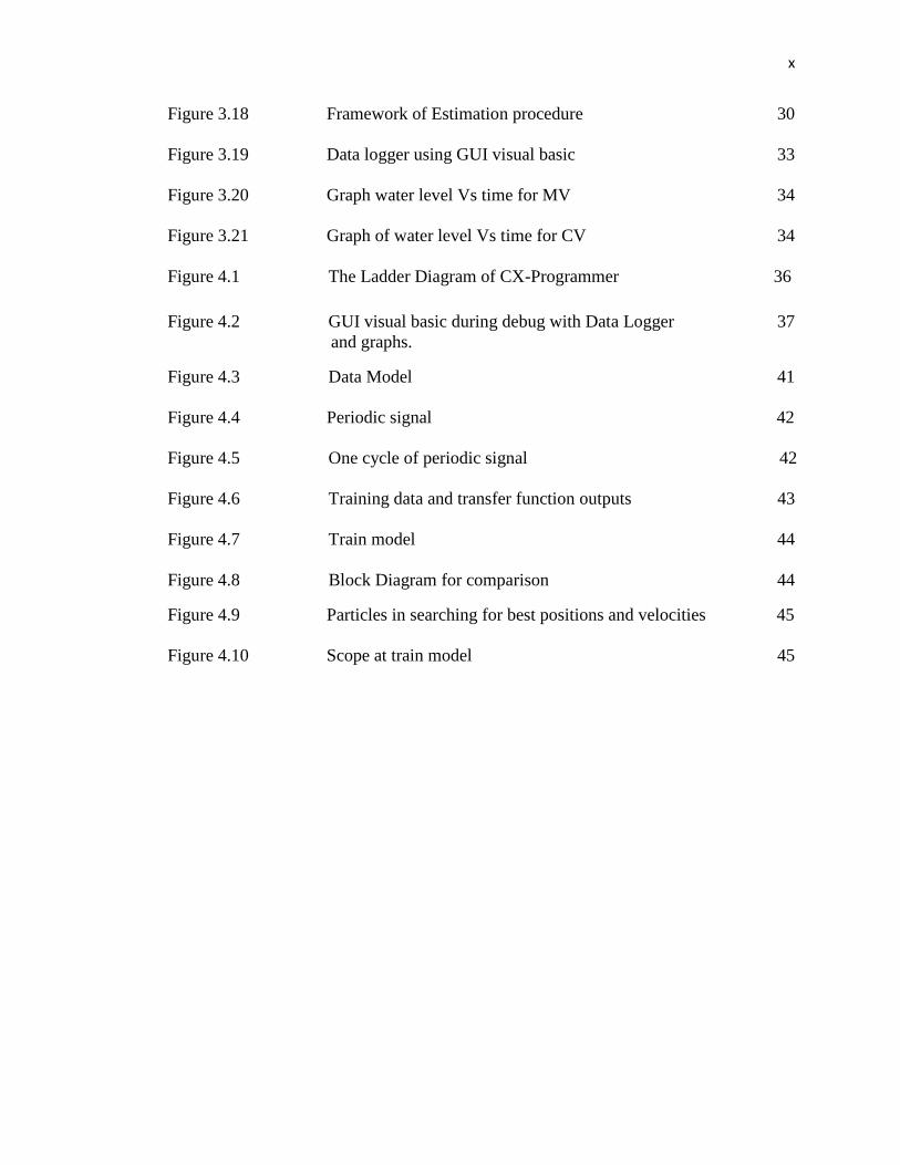
Figure 3.18 Framework of Estimation procedure 30
Figure 3.19 Data logger using GUI visual basic 33
Figure 3.20 Graph water level Vs time for MV 34
Figure 3.21 Graph of water level Vs time for CV 34
Figure 4.1 The Ladder Diagram of CX-Programmer 36
Figure 4.2 GUI visual basic during debug with Data Logger 37
and graphs.
Figure 4.3 Data Model 41
Figure 4.4 Periodic signal 42
Figure 4.5 One cycle of periodic signal 42
Figure 4.6 Training data and transfer function outputs 43
Figure 4.7 Train model 44
Figure 4.8 Block Diagram for comparison 44
Figure 4.9 Particles in searching for best positions and velocities 45
Figure 4.10 Scope at train model 45

xi
LIST OF ABBREVIATIONS
PLC Programmable Logic Control
SISO Single Input Single Output
MIMO Multi Input Multi Output
Analog I/O Analog Input Output
DM Data Memory
CPU Computer Processing Unit
PSO Particle Swarm Optimization
GUI Graphical User Interface
MSE Mean Square Error
MV Manipulated Variable
CV Controlled Variable
SP Set Point
1
CHAPTER 1
INTRODUCTION
1.1 Introduction
1.1.1 Coupled Tank Liquid Level System
The coupled tank apparatus CTS-001 is a computer-controlled coupled-tank
system used for liquid level control. The concept of virtual instrumentation is introduced
in CTS-001. By using virtual instrumentation techniques, the need for traditional
dedicated user interfaces on individual instruments can be eliminated [1]. Instead, the
computer can be used to provide the interface normally required on each of the
individual instruments, reducing cost and complexity. Virtual instrumentation also
allows the user to make major modification to the instrument by simply changing a
software program. For example, the computer can be used to carry out the functions of
an oscilloscope for displaying input and output response.
2
1.1.2 Parameter Identification
A Parameter Identification or in the other word as model is a set of mathematical
equations that are intended to capture the effect of certain system variables on a certain
other system variables. It is usually neither possible nor necessary to model the effect of
every variable on every other variable; one therefore limits oneself to certain subsets, for
example, the effect of disturbance on output [2]. A model is never perfect and it is
therefore always associated with a modeling error. The importance of this mathematical
model implemented for the Coupled Tank Water Level systems are it is frequently
observed in practice in control plant in today’s larger industries and it can be easily use
in future when doing MATLAB simulation.
The most traditional system identification techniques are prediction error method
(PEM) and the instrument variable method (IVM). Though these traditional
identification techniques offer good solution to many real-life systems, they have certain
issues like difficulty in determining the model structure and numerical reliability due to
need of solving the multidimensional nonlinear optimization problem in PEM case or
system of linear equations in IVM case [3]. In another research, it introduced Transfer
Function Matrix which is based on the transfer function approach, for example, direct
polynomial form of TF and direct frequency domain identification.
1.1.3 Particle Swarm Optimization
The Particle Swarm Optimization (PSO) algorithms are populated-based research
algorithm based on the simulation of the social behavior of birds within a flock [4]. They
work in the same way, which is, updating the population of individuals by applying
some kind of operators according to the fitness information obtain from the environment
so that the individuals of the population can be expected to move toward better solution
areas [5]. PSO is one from other Intelligent Method of Parameter Identification that is
3
famously used in today control process because it has stochastic search capability and
robustness [6].
Thus, in this paper, it proposes the use of Particle Swarm Optimization in
identifying a fitness function for the mathematical equation. The objectives of this
project are to identify and obtain the mathematical characteristic of the Coupled Tank
Liquid Level system using a suitable parameter identification technique which is the
Intelligent Method. Secondly is to develop GUI which will display the actual system
performance (in terms of graphs) along with the model performance. In addition to that,
both performances will also be analyzed in terms of transient and steady-state responses.
1.2 Problem Statement
There are three major statements that have been emphasized in this project which
are Coupled Tank Water Level System, Programmable Logic Controller and Parameter
Identification.
1.2.1 Coupled Tank Liquid Level System
Coupled Tank is very special and unique due to the coupled function. There are
two major applications in Coupled Tank which is SISO (Single Input Single Output) and
MIMO (Multiple Input Multiple Output). The level of water entering tank 1 will be
affected by the water level in tank 2. In industrial control application, it is often required
to control Coupled Tank Water Level System. It is very popular and widely used in
control process industries.
4
1.2.2 Programmable Logic Controller
Programmable Logic Controller can be thought of as Industrial Computers with
specially designed architecture in both their central units (the PLC itself) and their
interfacing circuitry to field devices (input /output connections to the real world). PLC is
able to received analog external input and produced analog output for its functionality.
1.2.3 Parameter Identification
In Parameter Identification, Particle Swarm Optimization Method is applied
because of its free derivation. It required less number of computations to achieve same
error goals. PSO varied in real-time, so it is easy to use in software simulation.
1.3 Objective
The overall objectives of this project are;
1. To identify and obtain the Mathematical Model of Coupled Tank Liquid Level
System using Particle Swarm Optimization Method in terms of its transfer
function.
2. To estimate the parameter coefficient of the transfer function utilizing an
intelligent technique namely Particle Swarm Optimization.
1.4 Scope of Project
The scopes of this project are;
1. To determine the modeling mathematical equation of Coupled Tank Water Level
System using Particle Swarm Optimization.

5
2. To compare the modeling output with simulated output to obtain error less
between both output.
3. To develop GUI that will display the simulated and model performance in terms of
graph
4. To analyze the model performance in terms of transient and steady-state response.
6
CHAPTER 2
LITERATURE REVIEW
2.1 Introduction
In this chapter, all the important information related to this project are reviewed.
The sources of this information are mains from journals, conference papers, manuals,
and website. Besides that, the literature review can give a brief explanation about
Parameter Identification and the important of using Particle Swarm Optimization in
order to obtain the mathematical equation which best representing the Coupled Tank
Liquid Level System.
2.2 Coupled Tank Liquid Level System
The reservoir contains two PWM operated motor pumps. These pumps use either
0-5V analog voltage (internal signal conditioning system convert analog to PWM
(digital signal)) or external PWM sources for their application. Flow rates of water into
tank can be varied by change of these pump voltages. There is a baffle plate separating
7
the two tanks which can be slide up and down to vary interaction and coupling
capacitive probes, one in each tank, provided to measure water level. Output signals
from these probes are conditioned to give 0-5V analog output. A water outlet at side
near base of each tank connected by a flexible tube returns water to reservoir [1].
2.2.1 Coupled Tank Liquid Level System Application
The industrial application of liquid level control is tremendous especially in
chemical process industries. Usually, level control exists in some of the control loops of
process control system. Otherwise in many other industrial applications are concerned
with level control, may it be a single loop level control or sometimes multi-loop level
control. In some cases, level controls that are available in the industries are for
interacting tanks. Hence, level control is one of the control system variables which are
very important in Process Industries.
2.3 Parameter Identification
In the design of adaptive control system, it is sometime necessary to estimate
parameters for systems represented by state-space response [2]. Some generic and user-
friendly tools are available for model identification. For example, System Identification
Toolbox of MATLAB that contains various techniques for identifying time-series and
state space, non parametric and parametric models, is a popular identification tool
among researchers and academicians.
2.3.1 Parameter Identification Application
Once the system (plant) generate the output in terms of graph , the usage of
Parameter Estimation problem is to find among all possible choices a particular set of
parameters which best describes the system. Depending on one’s definition of “best”

8
there are different approaches to such a Parameter Identification problem [2]. In this
research, Intelligent Method is used instead of Classical Method. In Intelligent Method,
Particle Swarm Optimization is selected to be used in this research based on the
popularity of this method in process industry.
2.4 Particle Swarm Optimization
PSO algorithm was developed in 1995 by James Kennedy (social-psychologist)
and Russell Eberhart (electrical engineer), which is a Robust Stochastic Optimization
technique based on the movement and intelligence of swarms. It uses a number of
particles that constitute a swarm moving around in the search space looking for the best
solution [6].
In PSO algorithm, a swarm consists of m-particle, in which each particle is
treated as a point in an N-dimensional space which adjusts its “flying” according to its
own flying experience as well as the flying experience of other particles. Each particle
uses velocity to determine the direction and value of its “flying”, which follow the
current optimum in an N-dimension space [6].
Each particle keeps track of its coordinates in the solution space which are
associated with the best solution that has achieved so far by that particle. This value is
called personal best Pbest. Another best value that is tracked by the PSO is the best
value obtained so far by any particle in the neighborhood of that particle. This value is
called global best, Gbest .The basic concept of PSO lies in accelerating each particle
toward its personal best and the global best locations.
PSO does not have genetic operators like crossover and mutation. Particles
update themselves with the internal velocity. They also have memory, which is
9
important to the algorithm. In PSO, only Gbest gives out the information to others. It is a
one way information sharing mechanism. The evolution only looks for the best solution.
2.5 Programmable Logic Controller
A programmable logic controller (PLC) is an industrial computer used to control
and automate complex systems. All CJ1 series use the same instruction set and I/O
modules, so existing programs and equipment can be easily reused. A common memory
area can help integrate processes or coordinate various activities. Besides, CJ1M also
provide the analog output with the current rating from 4mA to 20mA which the CQM1H
cannot provide both of them [7].
Programmable logic controllers are a relatively recent development in process
control technology. It is designed for use in an industrial environment, which uses a
programmable memory for integral storage of user-oriented instructions for
implementing specific functions such as logic, sequencing, timing, counting, and
arithmetic to control through digital or analog inputs and outputs, various types of
machines or processes [8].
2.5.1 PLC Application
Programmable logic controllers are widely used in industry and process control.
Programmable logic controllers are used in a wide spectrum of applications from factory
automation to waste water treatment plant controls and from chemical process plant
control to engine management systems. PLCs are used throughout industry to control
and monitor a wide range of machines and other movable components and systems. As a
part of process control, a PLC is used to monitor input signals from a variety of input
points (input sensors) which report events and conditions occurring in a controlled
process. For example, a PLC can monitor such input conditions as motor speed,
positioning, temperature, pressure and volumetric flow. Its associated peripherals are
10
designed so that they can be easily integrated into an industrial control system and easily
used in all their functions [9].
2.6 Matlab Simulink
Simulink is an environment for multi-domain simulation and Model-Based
Design for dynamic and embedded systems. It provides an interactive graphical
environment and a customizable set of block libraries that let you design, simulate,
implement, and test a variety of time-varying systems, including communications,
controls, signal processing, video processing, and image processing. Simulink provides a
graphical user interface for building math models as block diagrams. The graphical
interface is popular for developing dynamical models for many fields, such as
electronics, hydraulics, chemistry, and especially, control systems.
2.7 Graphical User Interface (GUI)
Microsoft released Visual Basic in 1987 and the latest is in 2008. It was the first
visual development tool from Microsoft, and it was to compete with C, C++, Pascal and
other well-known programming languages. Programmers have undergone a major
change in many years of programming various machines. Overall, it can class Visual
Basic as a Graphical User Interface (GUI). A GUI is a graphical (rather than purely
textual) user interface to a computer.
Today’s major operating systems provide a graphical user interface. Applications
typically use the elements of the GUI that come with the operating system and add their
own graphical user interface elements and ideas. When creating an application, many
object-oriented tools exist that facilitate writing a graphical user interface. Each GUI
element is defined as a class widget from which you can create object instances for your
application.