Embed Size (px)
Citation preview
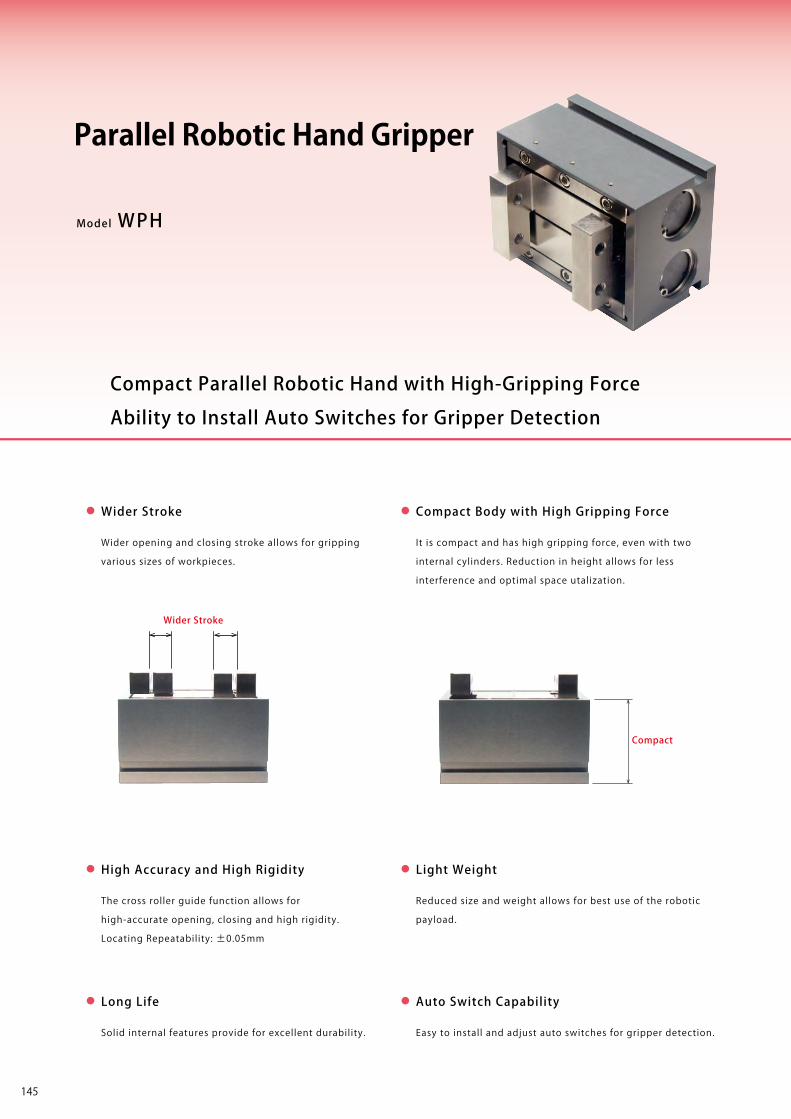
※ Please refer to P.173~P.180 for details on auto switches.
Locating +Clamp
Locating
Clamp
Cautions・Others
Support
Valve・Coupler
Robotic HandParallel Gripper
WPH
Robotic HandThree-Jaw Chuck
WPP
Robotic HandTwo-Jaw Chuck
WPQ
High-Power PneumaticHole Clamp
SWE
High-Power PneumaticSwing Clamp
WHE
High-Power PneumaticLink Clamp
WCE
PneumaticSwing Clamp
WHA
PneumaticLink Clamp
WCA
Air FlowControl Valve
BZW
ManifoldBlock
WHZ-MD
Model No.Indication SpecificationsFeatures Model No.Indication SpecificationsFeatures Performance
CurveExternalDimensions
InstallationMethod
CautionsP.171
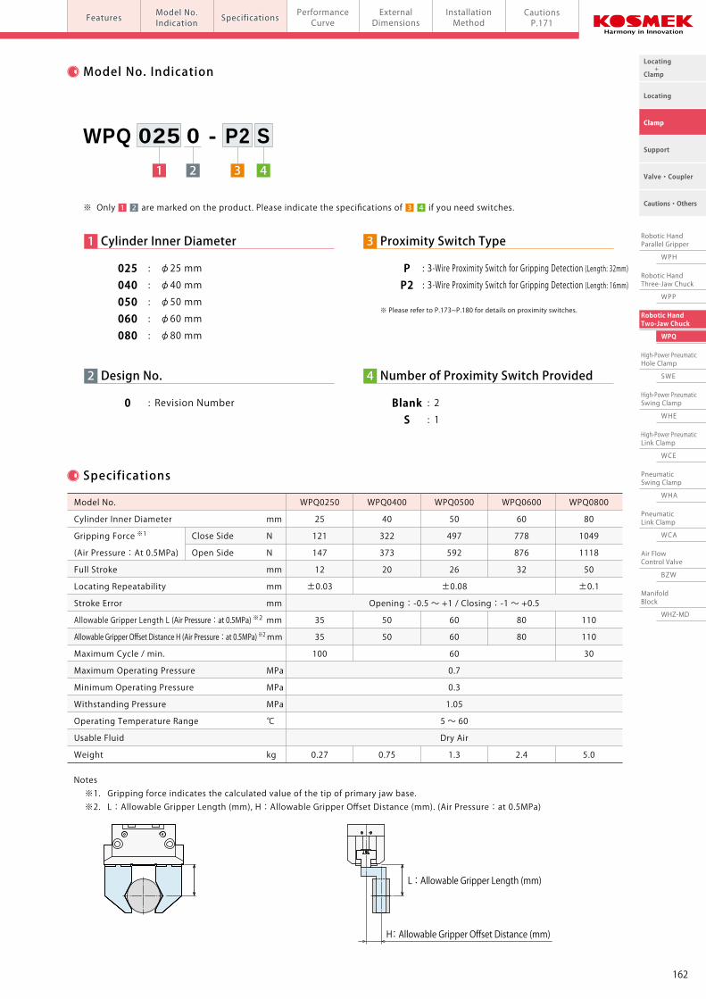
Model No. Indication
1 3 42
WPH 010 0 - A2 S
Model WPH
Wider Stroke
Wider opening and closing stroke allows for gripping
various sizes of workpieces.
It is compact and has high gripping force, even with two
internal cylinders. Reduction in height allows for less
interference and optimal space utalization.
Solid internal features provide for excellent durability.
The cross roller guide function allows for
high-accurate opening, closing and high rigidity.
Locating Repeatability: ±0.05mm
Compact Body with High Gripping Force
High Accuracy and High Rigidity
Long Life
Reduced size and weight allows for best use of the robotic
payload.
Light Weight
Easy to install and adjust auto switches for gripper detection.
Auto Switch Capability
Compact
Wider Stroke
Ability to Install Auto Switches for Gripper Detection
Compact Parallel Robotic Hand with High-Gripping Force
Parallel Robotic Hand Gripper
Specifications
Notes ※1. Gripping force indicates the calculated value of the tip of primary parallel base. ※2. L:Allowable Gripper Length (mm), H:Allowable Gripper Offset Distance (mm). (Air Pressure:at 0.5MPa)
※ Only are marked on the product. Please indicate the specifications of if you need switches.1 3 42
2 Design No.
0 : Revision Number
1 Cylinder Inner Diameter
010 : φ10 mm
016 : φ16 mm
020 : φ20 mm
4 Number of Auto Switch Provided
Blank : 2 S : 1
3 Auto Switch Type
A1/A2 : 2-Wire Reed Auto Switch (Cable: 1m) A1L/A2L : 2-Wire Reed Auto Switch (Cable: 3m) B1/B2 : 3-Wire Solid State Auto Switch (Cable: 1m) B1L/B2L : 3-Wire Solid State Auto Switch (Cable: 3m)
±0.05
Opening:-0.5 ~ +1 / Closing:-1 ~ +0.5
80
0.7
0.15
1.05
5 ~ 60
Dry Air
Model No.
Cylinder Inner Diameter mm
Gripping Force ※1
(Air Pressure:At 0.5MPa)
Full Stroke mm
Locating Repeatability mm
Stroke Error mm
Allowable Gripper Length L (Air Pressure:at 0.5MPa) ※2 mm
Allowable Gripper Offset Distance H (Air Pressure:at 0.5MPa) ※2 mm
Maximum Cycle / min.
Maximum Operating Pressure MPa
Minimum Operating Pressure MPa
Withstanding Pressure MPa
Operating Temperature Range ℃
Usable Fluid
Weight kg
WPH0100
10
15
40
20
0.14
33 86 135
WPH0160
16
20
50
30
0.32
WPH0200
20
20
60
40
0.7
Close Side N
L : Allowable Gripper Length (mm) L : Allowable Gripper Length (mm)
H: Allowable Gripper Offset Distance (mm)
145
※ Please refer to P.173~P.180 for details on auto switches.
Locating +Clamp
Locating
Clamp
Cautions・Others
Support
Valve・Coupler
Robotic HandParallel Gripper
WPH
Robotic HandThree-Jaw Chuck
WPP
Robotic HandTwo-Jaw Chuck
WPQ
High-Power PneumaticHole Clamp
SWE
High-Power PneumaticSwing Clamp
WHE
High-Power PneumaticLink Clamp
WCE
PneumaticSwing Clamp
WHA
PneumaticLink Clamp
WCA
Air FlowControl Valve
BZW
ManifoldBlock
WHZ-MD
Model No.Indication SpecificationsFeatures Model No.Indication SpecificationsFeatures Performance
CurveExternalDimensions
InstallationMethod
CautionsP.171
Model No. Indication
1 3 42
WPH 010 0 - A2 S
Model WPH
Wider Stroke
Wider opening and closing stroke allows for gripping
various sizes of workpieces.
It is compact and has high gripping force, even with two
internal cylinders. Reduction in height allows for less
interference and optimal space utalization.
Solid internal features provide for excellent durability.
The cross roller guide function allows for
high-accurate opening, closing and high rigidity.
Locating Repeatability: ±0.05mm
Compact Body with High Gripping Force
High Accuracy and High Rigidity
Long Life
Reduced size and weight allows for best use of the robotic
payload.
Light Weight
Easy to install and adjust auto switches for gripper detection.
Auto Switch Capability
Compact
Wider Stroke
Ability to Install Auto Switches for Gripper Detection
Compact Parallel Robotic Hand with High-Gripping Force
Parallel Robotic Hand Gripper
Specifications
Notes ※1. Gripping force indicates the calculated value of the tip of primary parallel base. ※2. L:Allowable Gripper Length (mm), H:Allowable Gripper Offset Distance (mm). (Air Pressure:at 0.5MPa)
※ Only are marked on the product. Please indicate the specifications of if you need switches.1 3 42
2 Design No.
0 : Revision Number
1 Cylinder Inner Diameter
010 : φ10 mm
016 : φ16 mm
020 : φ20 mm
4 Number of Auto Switch Provided
Blank : 2 S : 1
3 Auto Switch Type
A1/A2 : 2-Wire Reed Auto Switch (Cable: 1m) A1L/A2L : 2-Wire Reed Auto Switch (Cable: 3m) B1/B2 : 3-Wire Solid State Auto Switch (Cable: 1m) B1L/B2L : 3-Wire Solid State Auto Switch (Cable: 3m)
±0.05
Opening:-0.5 ~ +1 / Closing:-1 ~ +0.5
80
0.7
0.15
1.05
5 ~ 60
Dry Air
Model No.
Cylinder Inner Diameter mm
Gripping Force ※1
(Air Pressure:At 0.5MPa)
Full Stroke mm
Locating Repeatability mm
Stroke Error mm
Allowable Gripper Length L (Air Pressure:at 0.5MPa) ※2 mm
Allowable Gripper Offset Distance H (Air Pressure:at 0.5MPa) ※2 mm
Maximum Cycle / min.
Maximum Operating Pressure MPa
Minimum Operating Pressure MPa
Withstanding Pressure MPa
Operating Temperature Range ℃
Usable Fluid
Weight kg
WPH0100
10
15
40
20
0.14
33 86 135
WPH0160
16
20
50
30
0.32
WPH0200
20
20
60
40
0.7
Close Side N
L : Allowable Gripper Length (mm) L : Allowable Gripper Length (mm)
H: Allowable Gripper Offset Distance (mm)
146
Locating +Clamp
Locating
Clamp
Cautions・Others
Support
Valve・Coupler
Robotic HandParallel Gripper
WPH
Robotic HandThree-Jaw Chuck
WPP
Robotic HandTwo-Jaw Chuck
WPQ
High-Power PneumaticHole Clamp
SWE
High-Power PneumaticSwing Clamp
WHE
High-Power PneumaticLink Clamp
WCE
PneumaticSwing Clamp
WHA
PneumaticLink Clamp
WCA
Air FlowControl Valve
BZW
ManifoldBlock
WHZ-MD
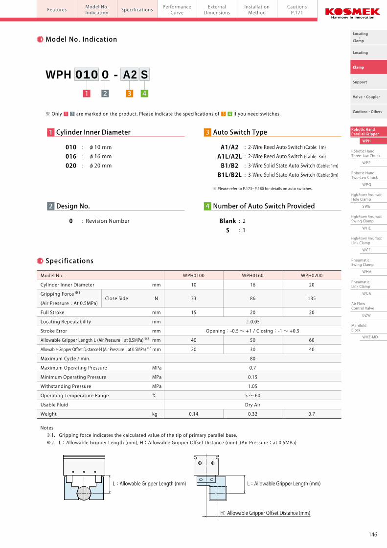
PerformanceCurvePneumatic Robotic Hands Parallel Robotic Hand Gripper model WPH
ModelNo. Indication SpecificationsFeatures Performance
CurveExternalDimensions
InstallationMethod
CautionsP.171
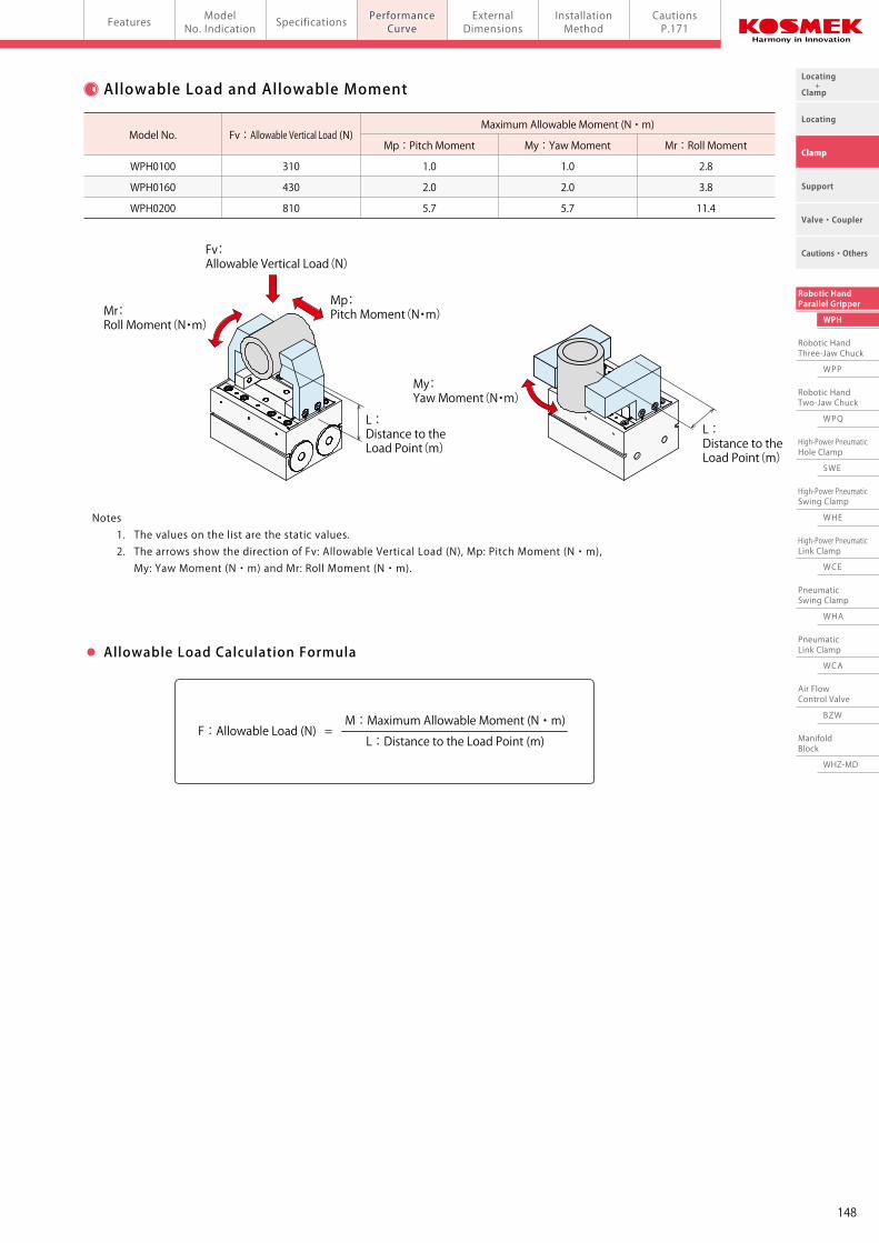
Gripping Force Performance Curve Allowable Load and Allowable Moment
Notes 1. The values on the list are the static values. 2. The arrows show the direction of Fv: Allowable Vertical Load (N), Mp: Pitch Moment (N・m), My: Yaw Moment (N・m) and Mr: Roll Moment (N・m).
Maximum Allowable Moment (N・m)
Mp:Pitch Moment My:Yaw Moment Mr:Roll MomentFv:Allowable Vertical Load (N)
WPH0100 310 1.0 1.0 2.8
WPH0160 430 2.0 2.0 3.8
WPH0200 810 5.7 5.7 11.4
Model No.
M:Maximum Allowable Moment (N・m)F:Allowable Load (N) = L:Distance to the Load Point (m)
0.7
0.5
0.3
0.15
WPH0100 Gripping Force (N)
Gripper Length L (mm)
L=5 L=10 L=15 L=20 L=30 L=40
48 47 47 46 45 44
34 34 33 33 32 31
21 20 20 20 19 19
10 10 10 10 10 9
0.7
0.5
0.3
0.15
WPH0160 Gripping Force (N)
Gripper Length L (mm)
L=5 L=10 L=20 L=30 L=40 L=50
123 122 121 119 117 115
88 87 86 85 84 82
53 52 52 51 50 49
26 26 26 25 25 25
0.7
0.5
0.3
0.15
WPH0200 Gripping Force (N)
Gripper Length L (mm)
L=10 L=20 L=30 L=40 L=50 L=60
192 189 187 185 182 180
137 135 134 132 130 128
82 81 80 79 78 77
41 41 40 40 39 39
Non-Usable Range (■)
0 10 20 30 400
Gripper Length (mm)
P=0.7MPa
P=0.5MPa
P=0.3MPa
P=0.15MPaGripping Force (N)
50
40
30
20
10
Non-Usable Range (■)
0 10 20 30 40 500
Gripper Length (mm)
Gripping Force (N)
140
120
100
80
60
40
20
Non-Usable Range (■)
0 10 20 30 40 50 600
Gripper Length (mm)
Gripping Force (N)
200
150
100
50
P=0.7MPa
P=0.5MPa
P=0.3MPa
P=0.15MPa
P=0.7MPa
P=0.5MPa
P=0.3MPa
P=0.15MPa
L : Gripper Length (mm)
L : Distance to the Load Point(m)
Mp: Pitch Moment(N・m)
My: Yaw Moment(N・m)
Mr: Roll Moment(N・m)
Fv: Allowable Vertical Load(N)
L : Distance to the Load Point(m)
F : Gripping Force (N)
P : Air Pressure (MPa)
Notes 1. This chart and graph show the relationship among: F: Gripping Force (N), P: Air Pressure (MPa) and L: Gripper Length (mm). 2. Operation in the non-usable range may cause deformation, galling or air leakage.
Allowable Load Calculation Formula
Air Pressure
(MPa)
Air Pressure
(MPa)
Air Pressure
(MPa)
147
Locating +Clamp
Locating
Clamp
Cautions・Others
Support
Valve・Coupler
Robotic HandParallel Gripper
WPH
Robotic HandThree-Jaw Chuck
WPP
Robotic HandTwo-Jaw Chuck
WPQ
High-Power PneumaticHole Clamp
SWE
High-Power PneumaticSwing Clamp
WHE
High-Power PneumaticLink Clamp
WCE
PneumaticSwing Clamp
WHA
PneumaticLink Clamp
WCA
Air FlowControl Valve
BZW
ManifoldBlock
WHZ-MD
PerformanceCurvePneumatic Robotic Hands Parallel Robotic Hand Gripper model WPH
ModelNo. Indication SpecificationsFeatures Performance
CurveExternalDimensions
InstallationMethod
CautionsP.171
Gripping Force Performance Curve Allowable Load and Allowable Moment
Notes 1. The values on the list are the static values. 2. The arrows show the direction of Fv: Allowable Vertical Load (N), Mp: Pitch Moment (N・m), My: Yaw Moment (N・m) and Mr: Roll Moment (N・m).
Maximum Allowable Moment (N・m)
Mp:Pitch Moment My:Yaw Moment Mr:Roll MomentFv:Allowable Vertical Load (N)
WPH0100 310 1.0 1.0 2.8
WPH0160 430 2.0 2.0 3.8
WPH0200 810 5.7 5.7 11.4
Model No.
M:Maximum Allowable Moment (N・m)F:Allowable Load (N) = L:Distance to the Load Point (m)
0.7
0.5
0.3
0.15
WPH0100 Gripping Force (N)
Gripper Length L (mm)
L=5 L=10 L=15 L=20 L=30 L=40
48 47 47 46 45 44
34 34 33 33 32 31
21 20 20 20 19 19
10 10 10 10 10 9
0.7
0.5
0.3
0.15
WPH0160 Gripping Force (N)
Gripper Length L (mm)
L=5 L=10 L=20 L=30 L=40 L=50
123 122 121 119 117 115
88 87 86 85 84 82
53 52 52 51 50 49
26 26 26 25 25 25
0.7
0.5
0.3
0.15
WPH0200 Gripping Force (N)
Gripper Length L (mm)
L=10 L=20 L=30 L=40 L=50 L=60
192 189 187 185 182 180
137 135 134 132 130 128
82 81 80 79 78 77
41 41 40 40 39 39
Non-Usable Range (■)
0 10 20 30 400
Gripper Length (mm)
P=0.7MPa
P=0.5MPa
P=0.3MPa
P=0.15MPaGripping Force (N)
50
40
30
20
10
Non-Usable Range (■)
0 10 20 30 40 500
Gripper Length (mm)
Gripping Force (N)
140
120
100
80
60
40
20
Non-Usable Range (■)
0 10 20 30 40 50 600
Gripper Length (mm)
Gripping Force (N)
200
150
100
50
P=0.7MPa
P=0.5MPa
P=0.3MPa
P=0.15MPa
P=0.7MPa
P=0.5MPa
P=0.3MPa
P=0.15MPa
L : Gripper Length (mm)
L : Distance to the Load Point(m)
Mp: Pitch Moment(N・m)
My: Yaw Moment(N・m)
Mr: Roll Moment(N・m)
Fv: Allowable Vertical Load(N)
L : Distance to the Load Point(m)
F : Gripping Force (N)
P : Air Pressure (MPa)
Notes 1. This chart and graph show the relationship among: F: Gripping Force (N), P: Air Pressure (MPa) and L: Gripper Length (mm). 2. Operation in the non-usable range may cause deformation, galling or air leakage.
Allowable Load Calculation Formula
Air Pressure
(MPa)
Air Pressure
(MPa)
Air Pressure
(MPa)
148
Locating +Clamp
Locating
Clamp
Cautions・Others
Support
Valve・Coupler
Robotic HandParallel Gripper
WPH
Robotic HandThree-Jaw Chuck
WPP
Robotic HandTwo-Jaw Chuck
WPQ
High-Power PneumaticHole Clamp
SWE
High-Power PneumaticSwing Clamp
WHE
High-Power PneumaticLink Clamp
WCE
PneumaticSwing Clamp
WHA
PneumaticLink Clamp
WCA
Air FlowControl Valve
BZW
ManifoldBlock
WHZ-MD
ExternalDimensionsPneumatic Robotic Hands Parallel Robotic Hand Gripper model WPHExternalDimensions
InstallationMethod
CautionsP.171
PerformanceCurve
Model No.Indication
SpecificationsFeatures
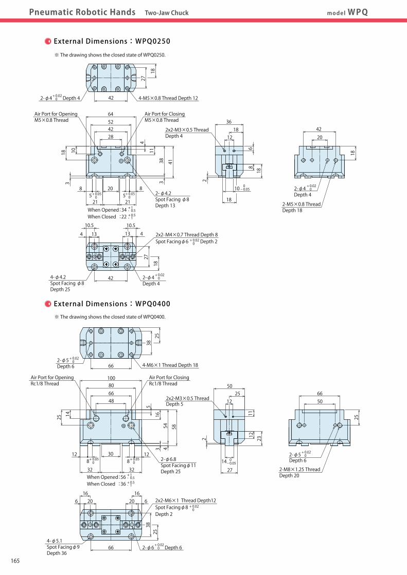
External Dimensions:WPH0100
External Dimensions:WPH0160
External Dimensions:WPH0200
※ The drawing shows the opened state of WPH0100. ※ The drawing shows the opened state of WPH0200.
※ The drawing shows the opened state of WPH0160.
34
40
2033
12
45
13 135
20
21
10
When Opened :38When Closed :18
68
18
21
40
2×2-M5×0.8 Thread
Air Port for OpeningM5×0.8 Thread 9.59.5
305 510
2-M5×0.8 Thread Depth 8
2-M5×0.8 Thread Depth 5 Air Port for ClosingM5×0.8 Thread
27.5
30
1421
310.5
34.5
9 104
14
22
8
When Opened :30When Closed :15
50
55
14
14
28
2×2-M4×0.7 Thread
Air Port for OpeningM5×0.8 Thread 77
223 38
2-M4×0.7 Thread Depth 5
2-M4×0.7 Thread Depth 5 Air Port for ClosingM5×0.8 Thread
Air Port for OpeningM5×0.8 Thread
Air Port for ClosingM5×0.8 Thread
37.5
60
27.5
42.5
12.5
55
18
5
27.5
27
10
When Opened:43When Closed:23
75
18
2×2-M5×0.8 Thread
55
3510 1010
2-M5×0.8 Thread Depth 12φ15 Depth 3+ 0.05 0
+ 1- 0.5+ 0.5- 1
+ 1- 0.5+ 0.5- 1
+ 1- 0.5+ 0.5- 1
149
Locating +Clamp
Locating
Clamp
Cautions・Others
Support
Valve・Coupler
Robotic HandParallel Gripper
WPH
Robotic HandThree-Jaw Chuck
WPP
Robotic HandTwo-Jaw Chuck
WPQ
High-Power PneumaticHole Clamp
SWE
High-Power PneumaticSwing Clamp
WHE
High-Power PneumaticLink Clamp
WCE
PneumaticSwing Clamp
WHA
PneumaticLink Clamp
WCA
Air FlowControl Valve
BZW
ManifoldBlock
WHZ-MD
ExternalDimensionsPneumatic Robotic Hands Parallel Robotic Hand Gripper model WPHExternalDimensions
InstallationMethod
CautionsP.171
PerformanceCurve
Model No.Indication
SpecificationsFeatures
External Dimensions:WPH0100
External Dimensions:WPH0160
External Dimensions:WPH0200
※ The drawing shows the opened state of WPH0100. ※ The drawing shows the opened state of WPH0200.
※ The drawing shows the opened state of WPH0160.
34
40
2033
12
45
13 135
20
21
10
When Opened :38When Closed :18
68
18
21
40
2×2-M5×0.8 Thread
Air Port for OpeningM5×0.8 Thread 9.59.5
305 510
2-M5×0.8 Thread Depth 8
2-M5×0.8 Thread Depth 5 Air Port for ClosingM5×0.8 Thread
27.5
30
1421
310.5
34.5
9 104
14
22
8
When Opened :30When Closed :15
50
55
14
14
28
2×2-M4×0.7 Thread
Air Port for OpeningM5×0.8 Thread 77
223 38
2-M4×0.7 Thread Depth 5
2-M4×0.7 Thread Depth 5 Air Port for ClosingM5×0.8 Thread
Air Port for OpeningM5×0.8 Thread
Air Port for ClosingM5×0.8 Thread
37.5
60
27.5
42.5
12.5
55
18
5
27.5
27
10
When Opened:43When Closed:23
75
18
2×2-M5×0.8 Thread
55
3510 1010
2-M5×0.8 Thread Depth 12φ15 Depth 3+ 0.05 0
+ 1- 0.5+ 0.5- 1
+ 1- 0.5+ 0.5- 1
+ 1- 0.5+ 0.5- 1
150
Locating +Clamp
Locating
Clamp
Cautions・Others
Support
Valve・Coupler
Robotic HandParallel Gripper
WPH
Robotic HandThree-Jaw Chuck
WPP
Robotic HandTwo-Jaw Chuck
WPQ
High-Power PneumaticHole Clamp
SWE
High-Power PneumaticSwing Clamp
WHE
High-Power PneumaticLink Clamp
WCE
PneumaticSwing Clamp
WHA
PneumaticLink Clamp
WCA
Air FlowControl Valve
BZW
ManifoldBlock
WHZ-MD
ExternalDimensions
InstallationMethodPneumatic Robotic Hands Parallel Robotic Hand Gripper model WPH
PerformanceCurve
ExternalDimensions
InstallationMethod
CautionsP.171
Model No.Indication SpecificationsFeatures
External Dimensions:Auto Switch Installation Method
For WPH0100
For WPH0160
For WPH0200
28
35 27
40 381 1
1
62.8
2.8
4.6
55 1 3838
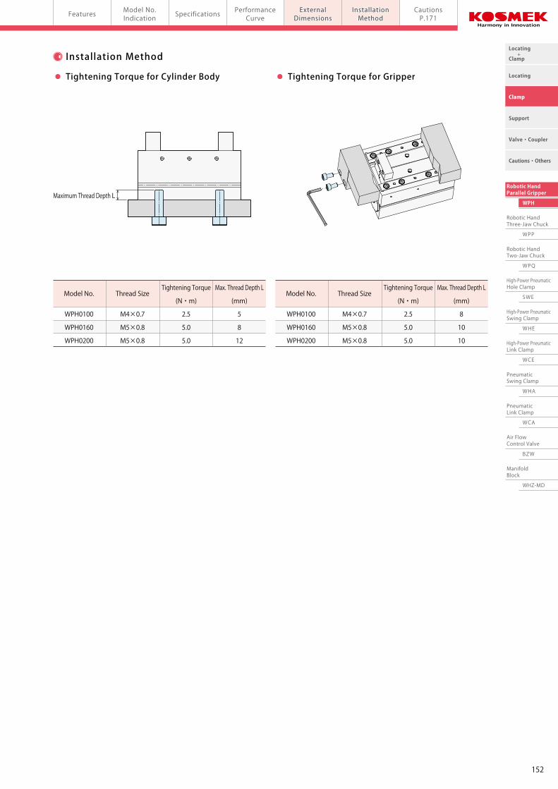
Maximum Thread Depth L
Model No.
WPH0100
WPH0160
WPH0200
Thread Size
M4×0.7
M5×0.8
M5×0.8
Tightening Torque
(N・m)
2.5
5.0
5.0
Max. Thread Depth L
(mm)
5
8
12
Model No.
WPH0100
WPH0160
WPH0200
Thread Size
M4×0.7
M5×0.8
M5×0.8
Tightening Torque
(N・m)
2.5
5.0
5.0
Max. Thread Depth L
(mm)
8
10
10
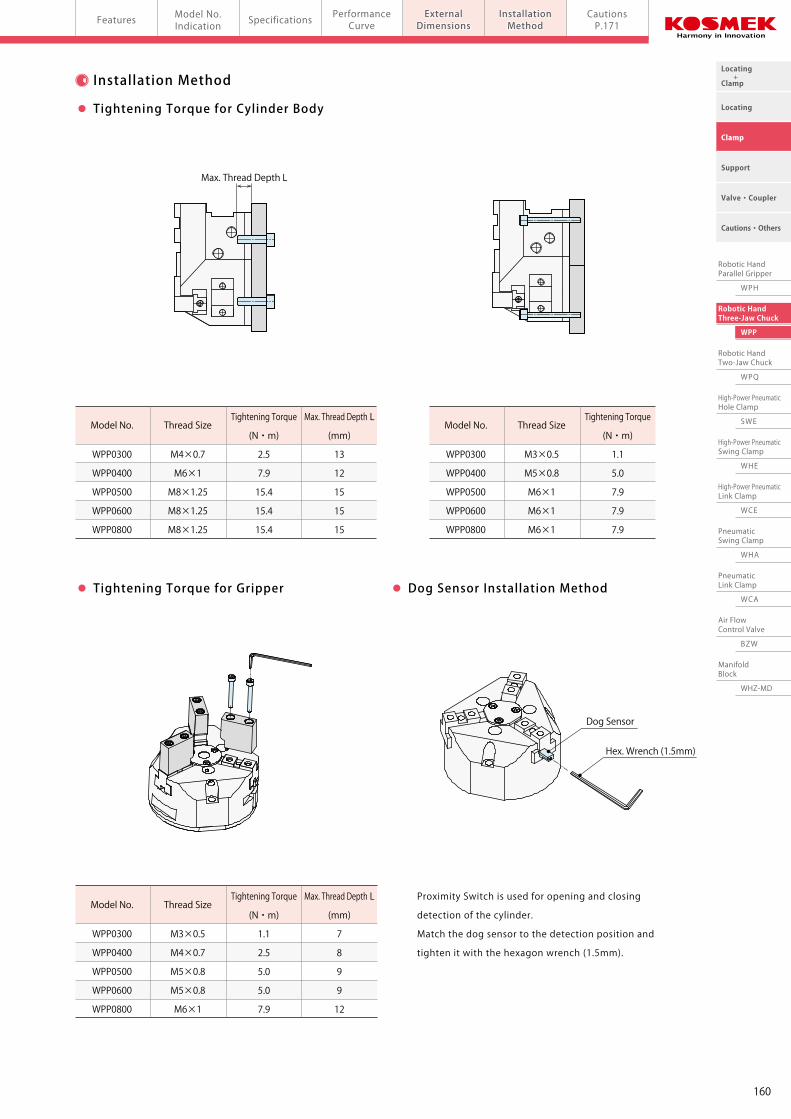
Tightening Torque for Cylinder Body Tightening Torque for Gripper
Auto SwitchJEP0000-A2□/B2□
Auto SwitchJEP0000-A2□/B2□
Auto Switch JEP0000-A1□/B1□
151
Locating +Clamp
Locating
Clamp
Cautions・Others
Support
Valve・Coupler
Robotic HandParallel Gripper
WPH
Robotic HandThree-Jaw Chuck
WPP
Robotic HandTwo-Jaw Chuck
WPQ
High-Power PneumaticHole Clamp
SWE
High-Power PneumaticSwing Clamp
WHE
High-Power PneumaticLink Clamp
WCE
PneumaticSwing Clamp
WHA
PneumaticLink Clamp
WCA
Air FlowControl Valve
BZW
ManifoldBlock
WHZ-MD
ExternalDimensions
InstallationMethodPneumatic Robotic Hands Parallel Robotic Hand Gripper model WPH
PerformanceCurve
ExternalDimensions
InstallationMethod
CautionsP.171
Model No.Indication SpecificationsFeatures
External Dimensions:Auto Switch Installation Method
For WPH0100
For WPH0160
For WPH0200
28
35 27
40 381 1
1
62.8
2.8
4.6
55 1 3838
Maximum Thread Depth L
Model No.
WPH0100
WPH0160
WPH0200
Thread Size
M4×0.7
M5×0.8
M5×0.8
Tightening Torque
(N・m)
2.5
5.0
5.0
Max. Thread Depth L
(mm)
5
8
12
Model No.
WPH0100
WPH0160
WPH0200
Thread Size
M4×0.7
M5×0.8
M5×0.8
Tightening Torque
(N・m)
2.5
5.0
5.0
Max. Thread Depth L
(mm)
8
10
10
Tightening Torque for Cylinder Body Tightening Torque for Gripper
Auto SwitchJEP0000-A2□/B2□
Auto SwitchJEP0000-A2□/B2□
Auto Switch JEP0000-A1□/B1□
152
Locating +Clamp
Locating
Clamp
Cautions・Others
Support
Valve・Coupler
Robotic HandParallel Gripper
WPH
Robotic HandThree-Jaw Chuck
WPP
Robotic HandTwo-Jaw Chuck
WPQ
High-Power PneumaticHole Clamp
SWE
High-Power PneumaticSwing Clamp
WHE
High-Power PneumaticLink Clamp
WCE
PneumaticSwing Clamp
WHA
PneumaticLink Clamp
WCA
Air FlowControl Valve
BZW
ManifoldBlock
WHZ-MD
Model No.Indication SpecificationsFeatures Model No.Indication SpecificationsFeatures Performance
CurveExternalDimensions
InstallationMethod
CautionsP.171
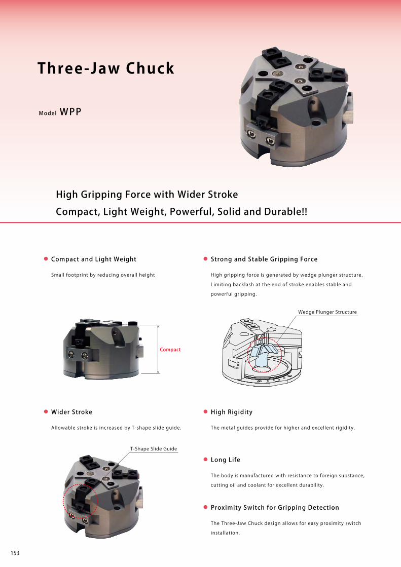
Model WPP
The Three-Jaw Chuck design allows for easy proximity switch
installation.
Proximity Switch for Gripping Detection
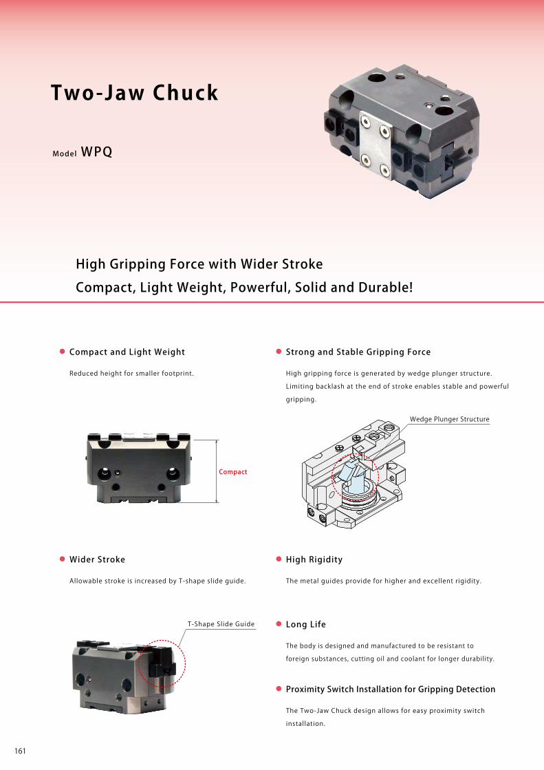
Compact and Light Weight
Small footprint by reducing overall height High gripping force is generated by wedge plunger structure.
Limiting backlash at the end of stroke enables stable and
powerful gripping.
Strong and Stable Gripping Force
The metal guides provide for higher and excellent rigidity.
High Rigidity
The body is manufactured with resistance to foreign substance,
cutting oil and coolant for excellent durability.
Long Life
Allowable stroke is increased by T-shape slide guide.
Wider Stroke
Wedge Plunger Structure
T-Shape Slide Guide
Compact
Compact, Light Weight, Powerful, Solid and Durable!!
High Gripping Force with Wider Stroke
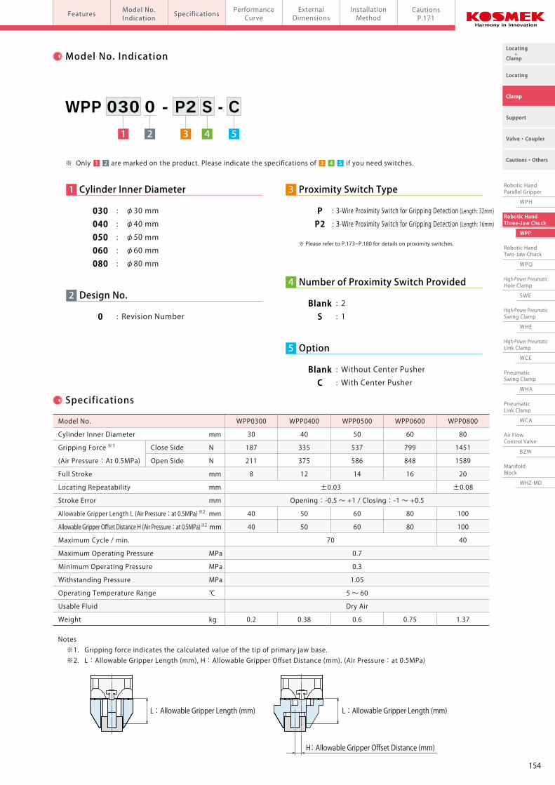
Three-Jaw Chuck1 3 4 52
WPP 030 0 - P2 S - C
2 Design No.
0 : Revision Number
1 Cylinder Inner Diameter
030 : φ30 mm
040 : φ40 mm
050 : φ50 mm
060 : φ60 mm
080 : φ80 mm
4 Number of Proximity Switch Provided
Blank : 2 S : 1
5 Option
Blank : Without Center Pusher C : With Center Pusher
3 Proximity Switch Type
P : 3-Wire Proximity Switch for Gripping Detection (Length: 32mm) P2 : 3-Wire Proximity Switch for Gripping Detection (Length: 16mm)
Model No. Indication
Specifications
±0.03
Opening:-0.5 ~ +1 / Closing:-1 ~ +0.5
70
0.7
0.3
1.05
5 ~ 60
Dry Air
Model No.
Cylinder Inner Diameter mm
Gripping Force ※1 Close Side N
(Air Pressure:At 0.5MPa) Open Side N
Full Stroke mm
Locating Repeatability mm
Stroke Error mm
Allowable Gripper Length L (Air Pressure:at 0.5MPa) ※2 mm
Allowable Gripper Offset Distance H (Air Pressure:at 0.5MPa) ※2 mm
Maximum Cycle / min.
Maximum Operating Pressure MPa
Minimum Operating Pressure MPa
Withstanding Pressure MPa
Operating Temperature Range ℃
Usable Fluid
Weight kg
WPP0300
30
187
211
8
40
40
0.2
WPP0400
40
335
375
12
50
50
0.38
WPP0500
50
537
586
14
60
60
0.6
WPP0600
60
799
848
16
80
80
0.75
WPP0800
80
1451
1589
20
±0.08
100
100
40
1.37
Notes ※1. Gripping force indicates the calculated value of the tip of primary jaw base. ※2. L:Allowable Gripper Length (mm), H:Allowable Gripper Offset Distance (mm). (Air Pressure:at 0.5MPa)
H: Allowable Gripper Offset Distance (mm)
L : Allowable Gripper Length (mm) L : Allowable Gripper Length (mm)
※ Please refer to P.173~P.180 for details on proximity switches.
5※ Only are marked on the product. Please indicate the specifications of if you need switches.1 3 42
153
Locating +Clamp
Locating
Clamp
Cautions・Others
Support
Valve・Coupler
Robotic HandParallel Gripper
WPH
Robotic HandThree-Jaw Chuck
WPP
Robotic HandTwo-Jaw Chuck
WPQ
High-Power PneumaticHole Clamp
SWE
High-Power PneumaticSwing Clamp
WHE
High-Power PneumaticLink Clamp
WCE
PneumaticSwing Clamp
WHA
PneumaticLink Clamp
WCA
Air FlowControl Valve
BZW
ManifoldBlock
WHZ-MD
Model No.Indication SpecificationsFeatures Model No.Indication SpecificationsFeatures Performance
CurveExternalDimensions
InstallationMethod
CautionsP.171
Model WPP
The Three-Jaw Chuck design allows for easy proximity switch
installation.
Proximity Switch for Gripping Detection
Compact and Light Weight
Small footprint by reducing overall height High gripping force is generated by wedge plunger structure.
Limiting backlash at the end of stroke enables stable and
powerful gripping.
Strong and Stable Gripping Force
The metal guides provide for higher and excellent rigidity.
High Rigidity
The body is manufactured with resistance to foreign substance,
cutting oil and coolant for excellent durability.
Long Life
Allowable stroke is increased by T-shape slide guide.
Wider Stroke
Wedge Plunger Structure
T-Shape Slide Guide
Compact
Compact, Light Weight, Powerful, Solid and Durable!!
High Gripping Force with Wider Stroke
Three-Jaw Chuck1 3 4 52
WPP 030 0 - P2 S - C
2 Design No.
0 : Revision Number
1 Cylinder Inner Diameter
030 : φ30 mm
040 : φ40 mm
050 : φ50 mm
060 : φ60 mm
080 : φ80 mm
4 Number of Proximity Switch Provided
Blank : 2 S : 1
5 Option
Blank : Without Center Pusher C : With Center Pusher
3 Proximity Switch Type
P : 3-Wire Proximity Switch for Gripping Detection (Length: 32mm) P2 : 3-Wire Proximity Switch for Gripping Detection (Length: 16mm)
Model No. Indication
Specifications
±0.03
Opening:-0.5 ~ +1 / Closing:-1 ~ +0.5
70
0.7
0.3
1.05
5 ~ 60
Dry Air
Model No.
Cylinder Inner Diameter mm
Gripping Force ※1 Close Side N
(Air Pressure:At 0.5MPa) Open Side N
Full Stroke mm
Locating Repeatability mm
Stroke Error mm
Allowable Gripper Length L (Air Pressure:at 0.5MPa) ※2 mm
Allowable Gripper Offset Distance H (Air Pressure:at 0.5MPa) ※2 mm
Maximum Cycle / min.
Maximum Operating Pressure MPa
Minimum Operating Pressure MPa
Withstanding Pressure MPa
Operating Temperature Range ℃
Usable Fluid
Weight kg
WPP0300
30
187
211
8
40
40
0.2
WPP0400
40
335
375
12
50
50
0.38
WPP0500
50
537
586
14
60
60
0.6
WPP0600
60
799
848
16
80
80
0.75
WPP0800
80
1451
1589
20
±0.08
100
100
40
1.37
Notes ※1. Gripping force indicates the calculated value of the tip of primary jaw base. ※2. L:Allowable Gripper Length (mm), H:Allowable Gripper Offset Distance (mm). (Air Pressure:at 0.5MPa)
H: Allowable Gripper Offset Distance (mm)
L : Allowable Gripper Length (mm) L : Allowable Gripper Length (mm)
※ Please refer to P.173~P.180 for details on proximity switches.
5※ Only are marked on the product. Please indicate the specifications of if you need switches.1 3 42
154
Locating +Clamp
Locating
Clamp
Cautions・Others
Support
Valve・Coupler
Robotic HandParallel Gripper
WPH
Robotic HandThree-Jaw Chuck
WPP
Robotic HandTwo-Jaw Chuck
WPQ
High-Power PneumaticHole Clamp
SWE
High-Power PneumaticSwing Clamp
WHE
High-Power PneumaticLink Clamp
WCE
PneumaticSwing Clamp
WHA
PneumaticLink Clamp
WCA
Air FlowControl Valve
BZW
ManifoldBlock
WHZ-MD
Pneumatic Robotic Hands Three-Jaw Chuck model WPPPerformanceCurve
PerformanceCurve
Model No.Indication SpecificationsFeatures External
DimensionsInstallationMethod
CautionsP.171
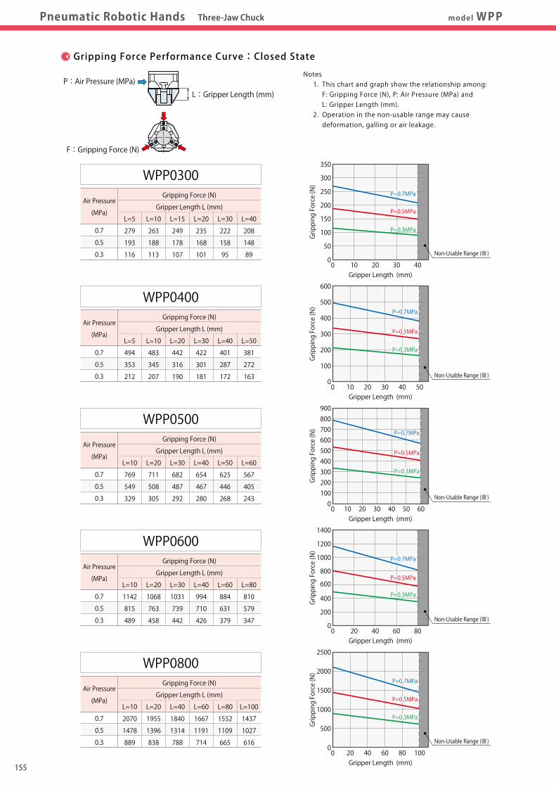
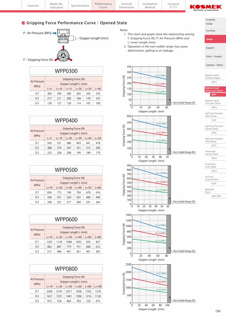
Gripping Force Performance Curve:Closed State Gripping Force Performance Curve:Opened State
0.7
0.5
0.3
WPP0300 Gripping Force (N)
Gripper Length L (mm)
L=5 L=10 L=15 L=20 L=30 L=40
304 296 280 265 244 234
217 211 200 184 178 167
130 127 120 114 107 100
0.7
0.5
0.3
WPP0400 Gripping Force (N)
Gripper Length L (mm)
L=5 L=10 L=20 L=30 L=40 L=50
543 531 486 463 441 418
388 379 347 331 315 299
233 228 208 199 189 179
0.7
0.5
0.3
WPP0500 Gripping Force (N)
Gripper Length L (mm)
L=10 L=20 L=30 L=40 L=50 L=60
834 772 740 704 678 616
596 551 529 507 484 440
358 331 317 304 291 264
0.7
0.5
0.3
WPP0600 Gripping Force (N)
Gripper Length L (mm)
L=10 L=20 L=30 L=40 L=60 L=80
1207 1129 1090 1052 935 857
862 807 779 751 668 612
517 484 467 451 401 367
0.7
0.5
0.3
WPP0800 Gripping Force (N)
Gripper Length L (mm)
L=10 L=20 L=40 L=60 L=80 L=100
2269 2143 2017 1828 1702 1576
1621 1531 1441 1306 1216 1126
973 918 864 783 729 675
0 10 20 30 400
Gripper Length (mm)
Gripping Force (N)
350
300
250
200
150
100
50
P=0.7MPa
P=0.5MPa
P=0.3MPa
0 10 20 30 40 500
Gripper Length (mm)
Gripping Force (N)
600
500
400
300
200
100
P=0.7MPa
P=0.5MPa
P=0.3MPa
Non-Usable Range (■)
Non-Usable Range (■)
0 10 20 30 40 50 600
Gripper Length (mm)
Gripping Force (N)
900800700600500400300200100
P=0.7MPa
P=0.5MPa
P=0.3MPa
Non-Usable Range (■)
0 20 40 80600
Gripper Length (mm)
Gripping Force (N)
1400
1200
1000
800
600
400
200
P=0.7MPa
P=0.5MPa
P=0.3MPa
Non-Usable Range (■)
0 20 40 80 100600
Gripper Length (mm)
Gripping Force (N)
2500
2000
1500
1000
500
P=0.7MPa
P=0.5MPa
P=0.3MPa
Non-Usable Range (■)
0.7
0.5
0.3
WPP0300 Gripping Force (N)
Gripper Length L (mm)
L=5 L=10 L=15 L=20 L=30 L=40
279 263 249 235 222 208
193 188 178 168 158 148
116 113 107 101 95 89
0.7
0.5
0.3
WPP0400 Gripping Force (N)
Gripper Length L (mm)
L=5 L=10 L=20 L=30 L=40 L=50
494 483 442 422 401 381
353 345 316 301 287 272
212 207 190 181 172 163
0.7
0.5
0.3
WPP0500 Gripping Force (N)
Gripper Length L (mm)
L=10 L=20 L=30 L=40 L=50 L=60
769 711 682 654 625 567
549 508 487 467 446 405
329 305 292 280 268 243
0.7
0.5
0.3
WPP0600 Gripping Force (N)
Gripper Length L (mm)
L=10 L=20 L=30 L=40 L=60 L=80
1142 1068 1031 994 884 810
815 763 739 710 631 579
489 458 442 426 379 347
0.7
0.5
0.3
WPP0800 Gripping Force (N)
Gripper Length L (mm)
L=10 L=20 L=40 L=60 L=80 L=100
2070 1955 1840 1667 1552 1437
1478 1396 1314 1191 1109 1027
889 838 788 714 665 616
0 10 20 30 400
Gripper Length (mm)
Gripping Force (N)
350
300
250
200
150
100
50
P=0.7MPa
P=0.5MPa
P=0.3MPa
0 10 20 30 40 500
Gripper Length (mm)
Gripping Force (N)
600
500
400
300
200
100
P=0.7MPa
P=0.5MPa
P=0.3MPa
0 10 20 30 40 50 600
Gripper Length (mm)
Gripping Force (N)
900800700600500400300200100
P=0.7MPa
P=0.5MPa
P=0.3MPa
0 20 40 80600
Gripper Length (mm)
Gripping Force (N)
1400
1200
1000
800
600
400
200
P=0.7MPa
P=0.5MPa
P=0.3MPa
0 20 40 80 100600
Gripper Length (mm)
Gripping Force (N)
2500
2000
1500
1000
500
P=0.7MPa
P=0.5MPa
P=0.3MPa
Non-Usable Range (■)
Non-Usable Range (■)
Non-Usable Range (■)
Non-Usable Range (■)
Non-Usable Range (■)
Notes 1. This chart and graph show the relationship among: F: Gripping Force (N), P: Air Pressure (MPa) and L: Gripper Length (mm). 2. Operation in the non-usable range may cause deformation, galling or air leakage.
Notes 1. This chart and graph show the relationship among: F: Gripping Force (N), P: Air Pressure (MPa) and L: Lever Length (mm). 2. Operation in the non-usable range may cause deformation, galling or air leakage.
L : Gripper Length (mm) L : Gripper Length (mm)
F : Gripping Force (N)
P : Air Pressure (MPa) P :Air Pressure (MPa)
F : Gripping Force (N)
Air Pressure
(MPa)
Air Pressure
(MPa)
Air Pressure
(MPa)
Air Pressure
(MPa)
Air Pressure
(MPa)
Air Pressure
(MPa)
Air Pressure
(MPa)
Air Pressure
(MPa)
Air Pressure
(MPa)
Air Pressure
(MPa)
155
Locating +Clamp
Locating
Clamp
Cautions・Others
Support
Valve・Coupler
Robotic HandParallel Gripper
WPH
Robotic HandThree-Jaw Chuck
WPP
Robotic HandTwo-Jaw Chuck
WPQ
High-Power PneumaticHole Clamp
SWE
High-Power PneumaticSwing Clamp
WHE
High-Power PneumaticLink Clamp
WCE
PneumaticSwing Clamp
WHA
PneumaticLink Clamp
WCA
Air FlowControl Valve
BZW
ManifoldBlock
WHZ-MD
Pneumatic Robotic Hands Three-Jaw Chuck model WPPPerformanceCurve
PerformanceCurve
Model No.Indication SpecificationsFeatures External
DimensionsInstallationMethod
CautionsP.171
Gripping Force Performance Curve:Closed State Gripping Force Performance Curve:Opened State
0.7
0.5
0.3
WPP0300 Gripping Force (N)
Gripper Length L (mm)
L=5 L=10 L=15 L=20 L=30 L=40
304 296 280 265 244 234
217 211 200 184 178 167
130 127 120 114 107 100
0.7
0.5
0.3
WPP0400 Gripping Force (N)
Gripper Length L (mm)
L=5 L=10 L=20 L=30 L=40 L=50
543 531 486 463 441 418
388 379 347 331 315 299
233 228 208 199 189 179
0.7
0.5
0.3
WPP0500 Gripping Force (N)
Gripper Length L (mm)
L=10 L=20 L=30 L=40 L=50 L=60
834 772 740 704 678 616
596 551 529 507 484 440
358 331 317 304 291 264
0.7
0.5
0.3
WPP0600 Gripping Force (N)
Gripper Length L (mm)
L=10 L=20 L=30 L=40 L=60 L=80
1207 1129 1090 1052 935 857
862 807 779 751 668 612
517 484 467 451 401 367
0.7
0.5
0.3
WPP0800 Gripping Force (N)
Gripper Length L (mm)
L=10 L=20 L=40 L=60 L=80 L=100
2269 2143 2017 1828 1702 1576
1621 1531 1441 1306 1216 1126
973 918 864 783 729 675
0 10 20 30 400
Gripper Length (mm)
Gripping Force (N)
350
300
250
200
150
100
50
P=0.7MPa
P=0.5MPa
P=0.3MPa
0 10 20 30 40 500
Gripper Length (mm)
Gripping Force (N)
600
500
400
300
200
100
P=0.7MPa
P=0.5MPa
P=0.3MPa
Non-Usable Range (■)
Non-Usable Range (■)
0 10 20 30 40 50 600
Gripper Length (mm)
Gripping Force (N)
900800700600500400300200100
P=0.7MPa
P=0.5MPa
P=0.3MPa
Non-Usable Range (■)
0 20 40 80600
Gripper Length (mm)
Gripping Force (N)
1400
1200
1000
800
600
400
200
P=0.7MPa
P=0.5MPa
P=0.3MPa
Non-Usable Range (■)
0 20 40 80 100600
Gripper Length (mm)
Gripping Force (N)
2500
2000
1500
1000
500
P=0.7MPa
P=0.5MPa
P=0.3MPa
Non-Usable Range (■)
0.7
0.5
0.3
WPP0300 Gripping Force (N)
Gripper Length L (mm)
L=5 L=10 L=15 L=20 L=30 L=40
279 263 249 235 222 208
193 188 178 168 158 148
116 113 107 101 95 89
0.7
0.5
0.3
WPP0400 Gripping Force (N)
Gripper Length L (mm)
L=5 L=10 L=20 L=30 L=40 L=50
494 483 442 422 401 381
353 345 316 301 287 272
212 207 190 181 172 163
0.7
0.5
0.3
WPP0500 Gripping Force (N)
Gripper Length L (mm)
L=10 L=20 L=30 L=40 L=50 L=60
769 711 682 654 625 567
549 508 487 467 446 405
329 305 292 280 268 243
0.7
0.5
0.3
WPP0600 Gripping Force (N)
Gripper Length L (mm)
L=10 L=20 L=30 L=40 L=60 L=80
1142 1068 1031 994 884 810
815 763 739 710 631 579
489 458 442 426 379 347
0.7
0.5
0.3
WPP0800 Gripping Force (N)
Gripper Length L (mm)
L=10 L=20 L=40 L=60 L=80 L=100
2070 1955 1840 1667 1552 1437
1478 1396 1314 1191 1109 1027
889 838 788 714 665 616
0 10 20 30 400
Gripper Length (mm)
Gripping Force (N)
350
300
250
200
150
100
50
P=0.7MPa
P=0.5MPa
P=0.3MPa
0 10 20 30 40 500
Gripper Length (mm)
Gripping Force (N)
600
500
400
300
200
100
P=0.7MPa
P=0.5MPa
P=0.3MPa
0 10 20 30 40 50 600
Gripper Length (mm)
Gripping Force (N)
900800700600500400300200100
P=0.7MPa
P=0.5MPa
P=0.3MPa
0 20 40 80600
Gripper Length (mm)
Gripping Force (N)
1400
1200
1000
800
600
400
200
P=0.7MPa
P=0.5MPa
P=0.3MPa
0 20 40 80 100600
Gripper Length (mm)
Gripping Force (N)
2500
2000
1500
1000
500
P=0.7MPa
P=0.5MPa
P=0.3MPa
Non-Usable Range (■)
Non-Usable Range (■)
Non-Usable Range (■)
Non-Usable Range (■)
Non-Usable Range (■)
Notes 1. This chart and graph show the relationship among: F: Gripping Force (N), P: Air Pressure (MPa) and L: Gripper Length (mm). 2. Operation in the non-usable range may cause deformation, galling or air leakage.
Notes 1. This chart and graph show the relationship among: F: Gripping Force (N), P: Air Pressure (MPa) and L: Lever Length (mm). 2. Operation in the non-usable range may cause deformation, galling or air leakage.
L : Gripper Length (mm) L : Gripper Length (mm)
F : Gripping Force (N)
P : Air Pressure (MPa) P :Air Pressure (MPa)
F : Gripping Force (N)
Air Pressure
(MPa)
Air Pressure
(MPa)
Air Pressure
(MPa)
Air Pressure
(MPa)
Air Pressure
(MPa)
Air Pressure
(MPa)
Air Pressure
(MPa)
Air Pressure
(MPa)
Air Pressure
(MPa)
Air Pressure
(MPa)
156
Pneumatic Robotic Hands Three-Jaw Chuck model WPPExternalDimensions
PerformanceCurve
ExternalDimensions
Model No.Indication
SpecificationsFeatures InstallationMethod
CautionsP.171
5 9.5
24
φ7
14
12
32.5
φ79
37.8
23
11.5
12
34
11
20 10
2.5 12
2
48
453
27
P.C.D. 65
19.530°
5 37.8
14.8
11
14.5
3-φ4 Depth 6
3×2-M5×0.8 Thread Depth 9
3-φ6.7
3×2-M3×0.5 Thread Depth 5
3-M8×1.25 ThreadDepth 15
Air Port for OpeningM5×0.8 Thread
Air Port for ClosingM5×0.8 Thread
2-φ6 Depth 12Spot Facing φ7Depth 5
5
13
62
18
10 8
9
φ5
13
9
3
2-φ3 Depth 10Spot Facing φ3.5 Depth 3
2
3
When Opened : 12.5
When Closed : 8.5
φ53
12
2522
6
56.5
10.4
25
3×2-M3×0.5 Thread Depth 5
35
32
19
13
3
P.C.D.44
3-M4×0.7 Thread Depth 13
24.5
30°
3-φ4 Depth 5
14
7
8
3×2-M3×0.5 Thread Depth 7 Air Port for Opening
M5×0.8 Thread
14.5
32
30°
21
9
18
28
10
10
32
φ67
3-φ4 Depth 5
10.5
413
3-φ5.1
3×2-M4×0.7 Thread Depth 8
3×2-M3×0.5 Thread Depth 5
3
45
42
4
20
26
18 10
3
φ6
58
2
2
15
10 10
12.4
3-M6×1 Thread Depth 12
P.C.D.56
2-φ4 Depth 12Spot Facing φ4.5 Depth 4
13
29
13
6
25
10
2.5
16φ85
11
35
40.5
3-φ6.7
23
13
3-φ5 Depth 6
11.5
12
5
3×2-M5×0.8 Thread Depth 9
16
14
30°48
51
21
30
5
3
2
40.5
11
1620
φ7
2
10
38.5
2-φ5 Depth 15Spot Facing φ5.5 Depth 5
32
3-φ6.7
φ106
45 50.5
27
13.5
14
16
620
11
3-φ6 Depth 6
3x2-M6×1 Thread Depth 12
30°
62
58
36
50.5
4
1415
241023
3
φ8
2
2
128
629
13
21
2-φ5 Depth 12Spot Facing φ5.5 Depth 6
49
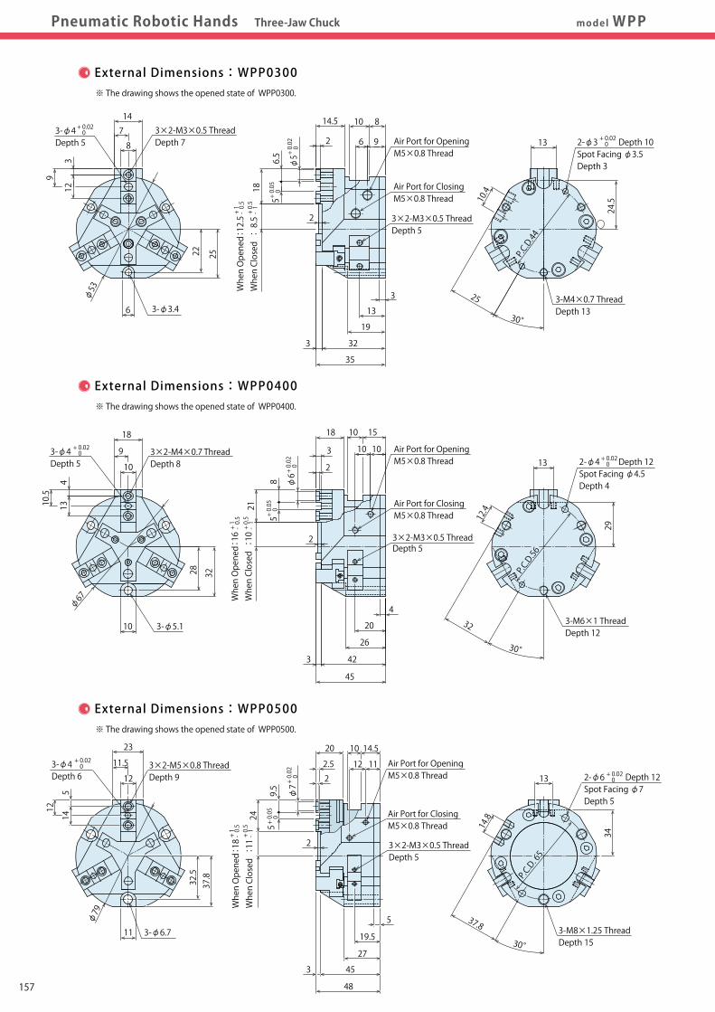
※ The drawing shows the opened state of WPP0300.
External Dimensions:WPP0300
※ The drawing shows the opened state of WPP0400.
External Dimensions:WPP0400
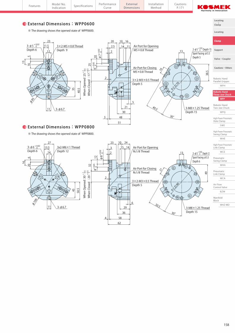
※ The drawing shows the opened state of WPP0600.
External Dimensions:WPP0600
※ The drawing shows the opened state of WPP0800.
External Dimensions:WPP0800
※ The drawing shows the opened state of WPP0500.
External Dimensions:WPP0500
3×2-M3×0.5 Thread Depth 5
Air Port for OpeningM5×0.8 Thread
Air Port for ClosingM5×0.8 Thread
Air Port for ClosingM5×0.8 Thread
Air Port for OpeningM5×0.8 Thread
Air Port for ClosingM5×0.8 Thread
3-M8×1.25 ThreadDepth 15
P.C.D.70
3-M8×1.25 ThreadDepth 15
P.C.D.90
2
3×2-M3×0.5 Thread Depth 5
Air Port for OpeningRc1/8 Thread
Air Port for ClosingRc1/8 Thread
+ 0.02 0
+ 0.02 0
+ 0.02 0
+ 0.02 0
+ 0.02 0
+ 0.02 0
+ 0.02
0
+ 0.05
0
+ 0.02 0
+ 0.02 0
+ 0.02
0
+ 0.05
0
+ 0.02
0
+ 0.05
0
+ 0.02 0
+ 0.02 0+
0.02
0
+ 0.05
0
+ 0.02
0
+ 0.05
0
3-φ3.4
+ 1- 0.5
+ 0.5
- 1
+ 1- 0.5
+ 0.5
- 1
+ 1- 0.5
+ 0.5
- 1+ 1- 0.5
+ 0.5
- 1
+ 1- 0.5
+ 0.5
- 1
When Opened : 16
When Closed : 10
When Opened :30
When Closed : 20
When Opened :25
When Closed :17
When Opened : 18
When Closed :11
Locating +Clamp
Locating
Clamp
Cautions・Others
Support
Valve・Coupler
Robotic HandParallel Gripper
WPH
Robotic HandThree-Jaw Chuck
WPP
Robotic HandTwo-Jaw Chuck
WPQ
High-Power PneumaticHole Clamp
SWE
High-Power PneumaticSwing Clamp
WHE
High-Power PneumaticLink Clamp
WCE
PneumaticSwing Clamp
WHA
PneumaticLink Clamp
WCA
Air FlowControl Valve
BZW
ManifoldBlock
WHZ-MD
157
Pneumatic Robotic Hands Three-Jaw Chuck model WPPExternalDimensions
PerformanceCurve
ExternalDimensions
Model No.Indication
SpecificationsFeatures InstallationMethod
CautionsP.171
5 9.5
24
φ7
14
12
32.5
φ79
37.8
23
11.5
12
34
11
20 10
2.5 12
2
48
453
27
P.C.D. 65
19.530°
5 37.8
14.8
11
14.5
3-φ4 Depth 6
3×2-M5×0.8 Thread Depth 9
3-φ6.7
3×2-M3×0.5 Thread Depth 5
3-M8×1.25 ThreadDepth 15
Air Port for OpeningM5×0.8 Thread
Air Port for ClosingM5×0.8 Thread
2-φ6 Depth 12Spot Facing φ7Depth 5
5
13
62
18
10 8
9
φ5
13
9
3
2-φ3 Depth 10Spot Facing φ3.5 Depth 3
2
3
When Opened : 12.5
When Closed : 8.5
φ53
12
2522
6
56.5
10.4
25
3×2-M3×0.5 Thread Depth 5
35
32
19
13
3
P.C.D.44
3-M4×0.7 Thread Depth 13
24.5
30°
3-φ4 Depth 5
14
7
8
3×2-M3×0.5 Thread Depth 7 Air Port for Opening
M5×0.8 Thread
14.5
32
30°
21
9
18
28
10
10
32
φ67
3-φ4 Depth 5
10.5
413
3-φ5.1
3×2-M4×0.7 Thread Depth 8
3×2-M3×0.5 Thread Depth 5
3
45
42
4
20
26
18 10
3
φ6
58
2
2
15
10 10
12.4
3-M6×1 Thread Depth 12
P.C.D.56
2-φ4 Depth 12Spot Facing φ4.5 Depth 4
13
29
13
6
25
10
2.5
16φ85
11
35
40.5
3-φ6.7
23
13
3-φ5 Depth 6
11.5
12
5
3×2-M5×0.8 Thread Depth 9
16
14
30°48
51
21
30
5
3
2
40.5
11
1620
φ7
2
10
38.5
2-φ5 Depth 15Spot Facing φ5.5 Depth 5
32
3-φ6.7
φ106
45 50.5
27
13.5
14
16
620
11
3-φ6 Depth 6
3x2-M6×1 Thread Depth 12
30°
62
58
36
50.5
4
1415
241023
3
φ8
2
2
128
629
13
21
2-φ5 Depth 12Spot Facing φ5.5 Depth 6
49
※ The drawing shows the opened state of WPP0300.
External Dimensions:WPP0300
※ The drawing shows the opened state of WPP0400.
External Dimensions:WPP0400
※ The drawing shows the opened state of WPP0600.
External Dimensions:WPP0600
※ The drawing shows the opened state of WPP0800.
External Dimensions:WPP0800
※ The drawing shows the opened state of WPP0500.
External Dimensions:WPP0500
3×2-M3×0.5 Thread Depth 5
Air Port for OpeningM5×0.8 Thread
Air Port for ClosingM5×0.8 Thread
Air Port for ClosingM5×0.8 Thread
Air Port for OpeningM5×0.8 Thread
Air Port for ClosingM5×0.8 Thread
3-M8×1.25 ThreadDepth 15
P.C.D.70
3-M8×1.25 ThreadDepth 15
P.C.D.90
2
3×2-M3×0.5 Thread Depth 5
Air Port for OpeningRc1/8 Thread
Air Port for ClosingRc1/8 Thread
+ 0.02 0
+ 0.02 0
+ 0.02 0
+ 0.02 0
+ 0.02 0
+ 0.02 0
+ 0.02
0
+ 0.05
0
+ 0.02 0
+ 0.02 0
+ 0.02
0
+ 0.05
0
+ 0.02
0
+ 0.05
0
+ 0.02 0
+ 0.02 0+
0.02
0
+ 0.05
0
+ 0.02
0
+ 0.05
0
3-φ3.4
+ 1- 0.5
+ 0.5
- 1
+ 1- 0.5
+ 0.5
- 1
+ 1- 0.5
+ 0.5
- 1+ 1- 0.5
+ 0.5
- 1
+ 1- 0.5
+ 0.5
- 1
When Opened : 16
When Closed : 10
When Opened :30
When Closed : 20
When Opened :25
When Closed :17
When Opened : 18
When Closed :11
Locating +Clamp
Locating
Clamp
Cautions・Others
Support
Valve・Coupler
Robotic HandParallel Gripper
WPH
Robotic HandThree-Jaw Chuck
WPP
Robotic HandTwo-Jaw Chuck
WPQ
High-Power PneumaticHole Clamp
SWE
High-Power PneumaticSwing Clamp
WHE
High-Power PneumaticLink Clamp
WCE
PneumaticSwing Clamp
WHA
PneumaticLink Clamp
WCA
Air FlowControl Valve
BZW
ManifoldBlock
WHZ-MD
158
Locating +Clamp
Locating
Clamp
Cautions・Others
Support
Valve・Coupler
Robotic HandParallel Gripper
WPH
Robotic HandThree-Jaw Chuck
WPP
Robotic HandTwo-Jaw Chuck
WPQ
High-Power PneumaticHole Clamp
SWE
High-Power PneumaticSwing Clamp
WHE
High-Power PneumaticLink Clamp
WCE
PneumaticSwing Clamp
WHA
PneumaticLink Clamp
WCA
Air FlowControl Valve
BZW
ManifoldBlock
WHZ-MD
Pneumatic Robotic Hands Three-Jaw Chuck model WPPExternalDimensions
InstallationMethod
ExternalDimensions
InstallationMethod
PerformanceCurve
Model No.Indication SpecificationsFeatures Cautions
P.171
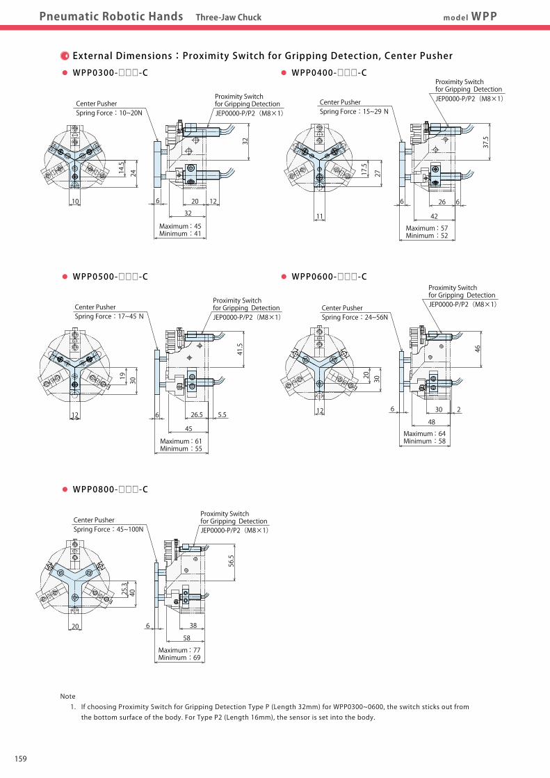
Proximity Switch for Gripping DetectionCenter Pusher
Spring Force:10~20N
6 12
32
32
2010
14.5
24Max. Thread Depth L
External Dimensions:Proximity Switch for Gripping Detection, Center Pusher
WPP0300-□□□-C
Installation Method
Tightening Torque for Cylinder Body
Tightening Torque for Gripper Dog Sensor Installation Method
Maximum :45Minimum :41
30
Center PusherSpring Force:24~56N
20
12
46
30
48
6 2
JEP0000-P/P2(M8×1)
WPP0600-□□□-C
Center PusherSpring Force:15~29 N
6
37.5
6
42
26
JEP0000-P/P2(M8×1)
11
17.5
27
WPP0400-□□□-C
4025.3
20
58
38
Center PusherSpring Force:45~100N
6
JEP0000-P/P2(M8×1)
56.5
WPP0800-□□□-C
3019
12
Center PusherSpring Force:17~45 N
5.526.5
41.5
JEP0000-P/P2(M8×1)
45
6
WPP0500-□□□-C
Hex. Wrench (1.5mm)
Dog Sensor
Model No.
WPP0300
WPP0400
WPP0500
WPP0600
WPP0800
Thread Size
M4×0.7
M6×1
M8×1.25
M8×1.25
M8×1.25
Tightening Torque
(N・m)
2.5
7.9
15.4
15.4
15.4
Max. Thread Depth L
(mm)
13
12
15
15
15
Model No.
WPP0300
WPP0400
WPP0500
WPP0600
WPP0800
Thread Size
M3×0.5
M4×0.7
M5×0.8
M5×0.8
M6×1
Tightening Torque
(N・m)
1.1
2.5
5.0
5.0
7.9
Max. Thread Depth L
(mm)
7
8
9
9
12
Model No.
WPP0300
WPP0400
WPP0500
WPP0600
WPP0800
Thread Size
M3×0.5
M5×0.8
M6×1
M6×1
M6×1
Tightening Torque
(N・m)
1.1
5.0
7.9
7.9
7.9
Proximity Switch is used for opening and closing
detection of the cylinder.
Match the dog sensor to the detection position and
tighten it with the hexagon wrench (1.5mm).
Note 1. If choosing Proximity Switch for Gripping Detection Type P (Length 32mm) for WPP0300~0600, the switch sticks out from the bottom surface of the body. For Type P2 (Length 16mm), the sensor is set into the body.
Maximum :57Minimum :52
Maximum :64Minimum :58Maximum :61
Minimum :55
Maximum :77Minimum :69
JEP0000-P/P2(M8×1)
Proximity Switch for Gripping Detection
Proximity Switch for Gripping Detection
Proximity Switch for Gripping Detection
Proximity Switch for Gripping Detection
159
Locating +Clamp
Locating
Clamp
Cautions・Others
Support
Valve・Coupler
Robotic HandParallel Gripper
WPH
Robotic HandThree-Jaw Chuck
WPP
Robotic HandTwo-Jaw Chuck
WPQ
High-Power PneumaticHole Clamp
SWE
High-Power PneumaticSwing Clamp
WHE
High-Power PneumaticLink Clamp
WCE
PneumaticSwing Clamp
WHA
PneumaticLink Clamp
WCA
Air FlowControl Valve
BZW
ManifoldBlock
WHZ-MD
Pneumatic Robotic Hands Three-Jaw Chuck model WPPExternalDimensions
InstallationMethod
ExternalDimensions
InstallationMethod
PerformanceCurve
Model No.Indication SpecificationsFeatures Cautions
P.171
Proximity Switch for Gripping DetectionCenter Pusher
Spring Force:10~20N
6 12
32
32
2010
14.5
24
Max. Thread Depth L
External Dimensions:Proximity Switch for Gripping Detection, Center Pusher
WPP0300-□□□-C
Installation Method
Tightening Torque for Cylinder Body
Tightening Torque for Gripper Dog Sensor Installation Method
Maximum :45Minimum :41
30
Center PusherSpring Force:24~56N
20
12
46
30
48
6 2
JEP0000-P/P2(M8×1)
WPP0600-□□□-C
Center PusherSpring Force:15~29 N
6
37.5
6
42
26
JEP0000-P/P2(M8×1)
11
17.5
27
WPP0400-□□□-C
4025.3
20
58
38
Center PusherSpring Force:45~100N
6
JEP0000-P/P2(M8×1)
56.5
WPP0800-□□□-C
3019
12
Center PusherSpring Force:17~45 N
5.526.5
41.5
JEP0000-P/P2(M8×1)
45
6
WPP0500-□□□-C
Hex. Wrench (1.5mm)
Dog Sensor
Model No.
WPP0300
WPP0400
WPP0500
WPP0600
WPP0800
Thread Size
M4×0.7
M6×1
M8×1.25
M8×1.25
M8×1.25
Tightening Torque
(N・m)
2.5
7.9
15.4
15.4
15.4
Max. Thread Depth L
(mm)
13
12
15
15
15
Model No.
WPP0300
WPP0400
WPP0500
WPP0600
WPP0800
Thread Size
M3×0.5
M4×0.7
M5×0.8
M5×0.8
M6×1
Tightening Torque
(N・m)
1.1
2.5
5.0
5.0
7.9
Max. Thread Depth L
(mm)
7
8
9
9
12
Model No.
WPP0300
WPP0400
WPP0500
WPP0600
WPP0800
Thread Size
M3×0.5
M5×0.8
M6×1
M6×1
M6×1
Tightening Torque
(N・m)
1.1
5.0
7.9
7.9
7.9
Proximity Switch is used for opening and closing
detection of the cylinder.
Match the dog sensor to the detection position and
tighten it with the hexagon wrench (1.5mm).
Note 1. If choosing Proximity Switch for Gripping Detection Type P (Length 32mm) for WPP0300~0600, the switch sticks out from the bottom surface of the body. For Type P2 (Length 16mm), the sensor is set into the body.
Maximum :57Minimum :52
Maximum :64Minimum :58Maximum :61
Minimum :55
Maximum :77Minimum :69
JEP0000-P/P2(M8×1)
Proximity Switch for Gripping Detection
Proximity Switch for Gripping Detection
Proximity Switch for Gripping Detection
Proximity Switch for Gripping Detection
160
Locating +Clamp
Locating
Clamp
Cautions・Others
Support
Valve・Coupler
Robotic HandParallel Gripper
WPH
Robotic HandThree-Jaw Chuck
WPP
Robotic HandTwo-Jaw Chuck
WPQ
High-Power PneumaticHole Clamp
SWE
High-Power PneumaticSwing Clamp
WHE
High-Power PneumaticLink Clamp
WCE
PneumaticSwing Clamp
WHA
PneumaticLink Clamp
WCA
Air FlowControl Valve
BZW
ManifoldBlock
WHZ-MD
Model No.Indication SpecificationsFeatures Model No.Indication SpecificationsFeatures Performance
CurveExternalDimensions
InstallationMethod
CautionsP.171
Model WPQ
The Two-Jaw Chuck design allows for easy proximity switch
installation.
Proximity Switch Installation for Gripping Detection
Compact and Light Weight
Reduced height for smaller footprint. High gripping force is generated by wedge plunger structure.
Limiting backlash at the end of stroke enables stable and powerful
gripping.
Strong and Stable Gripping Force
The metal guides provide for higher and excellent rigidity.
High Rigidity
The body is designed and manufactured to be resistant to
foreign substances, cutting oil and coolant for longer durability.
Long Life
Allowable stroke is increased by T-shape slide guide.
Wider Stroke
Wedge Plunger Structure
T-Shape Slide Guide
Compact
1 3 42
WPQ 025 0 - P2 S
2 Design No.
0 : Revision Number
1 Cylinder Inner Diameter
025 : φ25 mm
040 : φ40 mm
050 : φ50 mm
060 : φ60 mm
080 : φ80 mm
4 Number of Proximity Switch Provided
Blank : 2 S : 1
3 Proximity Switch Type
P : 3-Wire Proximity Switch for Gripping Detection (Length: 32mm) P2 : 3-Wire Proximity Switch for Gripping Detection (Length: 16mm)
Model No. Indication
Specifications
±0.08
Opening:-0.5 ~ +1 / Closing:-1 ~ +0.5
60
0.7
0.3
1.05
5 ~ 60
Dry Air
Model No.
Cylinder Inner Diameter mm
Gripping Force ※1 Close Side N
(Air Pressure:At 0.5MPa) Open Side N
Full Stroke mm
Locating Repeatability mm
Stroke Error mm
Allowable Gripper Length L (Air Pressure:at 0.5MPa) ※2 mm
Allowable Gripper Offset Distance H (Air Pressure:at 0.5MPa) ※2 mm
Maximum Cycle / min.
Maximum Operating Pressure MPa
Minimum Operating Pressure MPa
Withstanding Pressure MPa
Operating Temperature Range ℃
Usable Fluid
Weight kg
WPQ0250
25
121
147
12
±0.03
35
35
100
0.27
WPQ0400
40
322
373
20
50
50
0.75
WPQ0500
50
497
592
26
60
60
1.3
WPQ0600
60
778
876
32
80
80
2.4
WPQ0800
80
1049
1118
50
±0.1
110
110
30
5.0
L : Allowable Gripper Length (mm)
H: Allowable Gripper Offset Distance (mm)
Notes ※1. Gripping force indicates the calculated value of the tip of primary jaw base. ※2. L:Allowable Gripper Length (mm), H:Allowable Gripper Offset Distance (mm). (Air Pressure:at 0.5MPa)
※ Please refer to P.173~P.180 for details on proximity switches.
※ Only are marked on the product. Please indicate the specifications of if you need switches.1 3 42
Compact, Light Weight, Powerful, Solid and Durable!
High Gripping Force with Wider Stroke
Two-Jaw Chuck
161
Locating +Clamp
Locating
Clamp
Cautions・Others
Support
Valve・Coupler
Robotic HandParallel Gripper
WPH
Robotic HandThree-Jaw Chuck
WPP
Robotic HandTwo-Jaw Chuck
WPQ
High-Power PneumaticHole Clamp
SWE
High-Power PneumaticSwing Clamp
WHE
High-Power PneumaticLink Clamp
WCE
PneumaticSwing Clamp
WHA
PneumaticLink Clamp
WCA
Air FlowControl Valve
BZW
ManifoldBlock
WHZ-MD
Model No.Indication SpecificationsFeatures Model No.Indication SpecificationsFeatures Performance
CurveExternalDimensions
InstallationMethod
CautionsP.171
Model WPQ
The Two-Jaw Chuck design allows for easy proximity switch
installation.
Proximity Switch Installation for Gripping Detection
Compact and Light Weight
Reduced height for smaller footprint. High gripping force is generated by wedge plunger structure.
Limiting backlash at the end of stroke enables stable and powerful
gripping.
Strong and Stable Gripping Force
The metal guides provide for higher and excellent rigidity.
High Rigidity
The body is designed and manufactured to be resistant to
foreign substances, cutting oil and coolant for longer durability.
Long Life
Allowable stroke is increased by T-shape slide guide.
Wider Stroke
Wedge Plunger Structure
T-Shape Slide Guide
Compact
1 3 42
WPQ 025 0 - P2 S
2 Design No.
0 : Revision Number
1 Cylinder Inner Diameter
025 : φ25 mm
040 : φ40 mm
050 : φ50 mm
060 : φ60 mm
080 : φ80 mm
4 Number of Proximity Switch Provided
Blank : 2 S : 1
3 Proximity Switch Type
P : 3-Wire Proximity Switch for Gripping Detection (Length: 32mm) P2 : 3-Wire Proximity Switch for Gripping Detection (Length: 16mm)
Model No. Indication
Specifications
±0.08
Opening:-0.5 ~ +1 / Closing:-1 ~ +0.5
60
0.7
0.3
1.05
5 ~ 60
Dry Air
Model No.
Cylinder Inner Diameter mm
Gripping Force ※1 Close Side N
(Air Pressure:At 0.5MPa) Open Side N
Full Stroke mm
Locating Repeatability mm
Stroke Error mm
Allowable Gripper Length L (Air Pressure:at 0.5MPa) ※2 mm
Allowable Gripper Offset Distance H (Air Pressure:at 0.5MPa) ※2 mm
Maximum Cycle / min.
Maximum Operating Pressure MPa
Minimum Operating Pressure MPa
Withstanding Pressure MPa
Operating Temperature Range ℃
Usable Fluid
Weight kg
WPQ0250
25
121
147
12
±0.03
35
35
100
0.27
WPQ0400
40
322
373
20
50
50
0.75
WPQ0500
50
497
592
26
60
60
1.3
WPQ0600
60
778
876
32
80
80
2.4
WPQ0800
80
1049
1118
50
±0.1
110
110
30
5.0
L : Allowable Gripper Length (mm)
H: Allowable Gripper Offset Distance (mm)
Notes ※1. Gripping force indicates the calculated value of the tip of primary jaw base. ※2. L:Allowable Gripper Length (mm), H:Allowable Gripper Offset Distance (mm). (Air Pressure:at 0.5MPa)
※ Please refer to P.173~P.180 for details on proximity switches.
※ Only are marked on the product. Please indicate the specifications of if you need switches.1 3 42
Compact, Light Weight, Powerful, Solid and Durable!
High Gripping Force with Wider Stroke
Two-Jaw Chuck
162
Locating +Clamp
Locating
Clamp
Cautions・Others
Support
Valve・Coupler
Robotic HandParallel Gripper
WPH
Robotic HandThree-Jaw Chuck
WPP
Robotic HandTwo-Jaw Chuck
WPQ
High-Power PneumaticHole Clamp
SWE
High-Power PneumaticSwing Clamp
WHE
High-Power PneumaticLink Clamp
WCE
PneumaticSwing Clamp
WHA
PneumaticLink Clamp
WCA
Air FlowControl Valve
BZW
ManifoldBlock
WHZ-MD
Pneumatic Robotic Hands Two-Jaw Chuck model WPQModel No.Indication
SpecificationsFeatures ExternalDimensions
InstallationMethod
CautionsP.171
PerformanceCurve
PerformanceCurve
0 20 40 60 80 100110
0 20 40 60 80 100110
00
Gripper Length (mm)
Gripping Force (N)
250
50
100
150
200
0 10 20 30 40 500
Gripper Length (mm)
Gripping Force (N)
600
500
400
300
200
100
P=0.7MPa
P=0.5MPa
P=0.3MPa
0 10 20 30 40 50 600
Gripper Length (mm)
Gripping Force (N)
900800700600500400300200100
P=0.7MPa
P=0.5MPa
P=0.3MPa
0 20 40 80600
Gripper Length (mm)
Gripping Force (N)
1400
1200
1000
800
600
400
200
P=0.7MPa
P=0.5MPa
P=0.3MPa
0
Gripper Length (mm)
Gripping Force (N)
1800
2004006008001000120014001600
P=0.7MPa
P=0.5MPa
P=0.3MPa
Non-Usable Range (■)
Non-Usable Range (■)
Non-Usable Range (■)
0 10 20 30 350
Gripper Length (mm)
Gripping Force (N)
250
50
100
150
200
P=0.7MPa
P=0.5MPa
P=0.3MPa
0 10 20 30 40 500
Gripper Length (mm)
Gripping Force (N)
600
500
400
300
200
100
P=0.7MPa
P=0.5MPa
P=0.3MPa
0 10 20 30 40 50 600
Gripper Length (mm)
Gripping Force (N)
900800700600500400300200100
P=0.7MPa
P=0.5MPa
P=0.3MPa
0 20 40 80600
Gripper Length (mm)
Gripping Force (N)
1400
1200
1000
800
600
400
200
P=0.7MPa
P=0.5MPa
P=0.3MPa
0
Gripper Length (mm)
Gripping Force (N)
1800
2004006008001000120014001600
P=0.7MPa
P=0.5MPa
P=0.3MPa
Non-Usable Range (■)
Non-Usable Range (■)
Non-Usable Range (■)
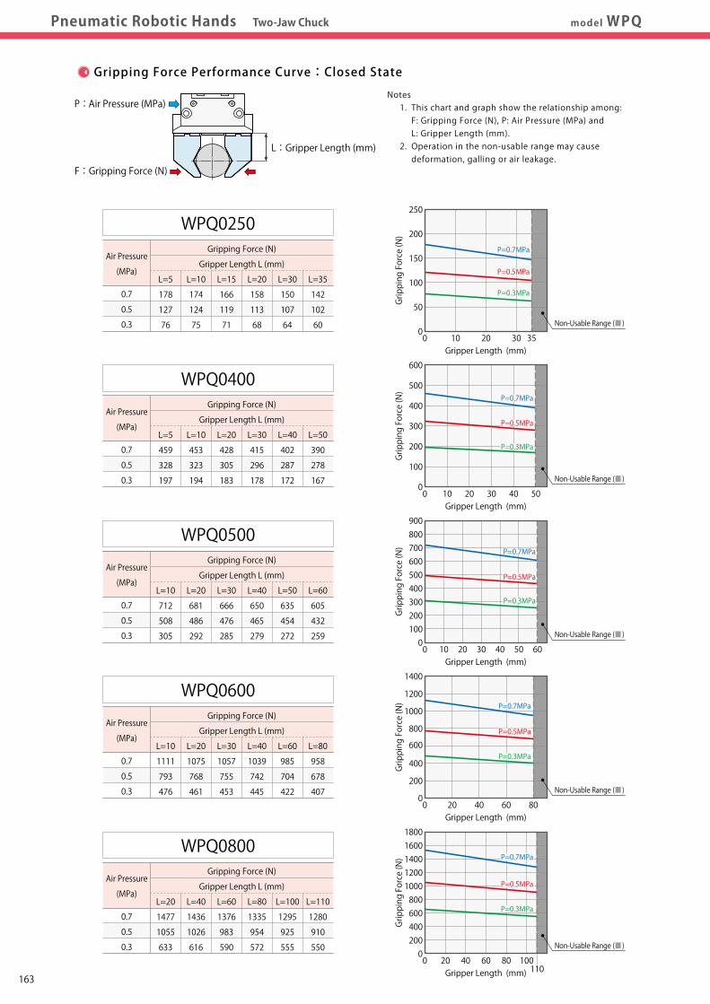
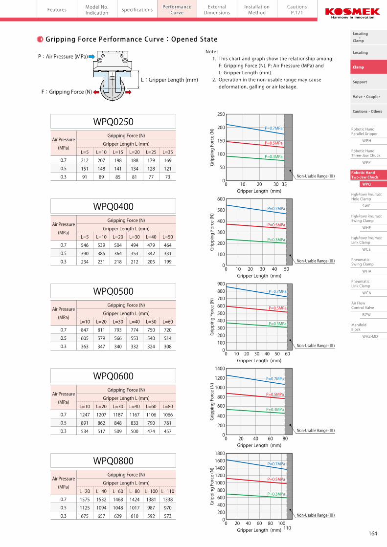
Gripping Force Performance Curve:Closed State Gripping Force Performance Curve:Opened State
0.7
0.5
0.3
WPQ0250 Gripping Force (N)
Gripper Length L (mm)
L=5 L=10 L=15 L=20 L=25 L=35
212 207 198 188 179 169
151 148 141 134 128 121
91 89 85 81 77 73
0.7
0.5
0.3
WPQ0400 Gripping Force (N)
Gripper Length L (mm)
L=5 L=10 L=20 L=30 L=40 L=50
546 539 504 494 479 464
390 385 364 353 342 331
234 231 218 212 205 199
0.7
0.5
0.3
WPQ0500 Gripping Force (N)
Gripper Length L (mm)
L=10 L=20 L=30 L=40 L=50 L=60
847 811 793 774 750 720
605 579 566 553 540 514
363 347 340 332 324 308
0.7
0.5
0.3
WPQ0600 Gripping Force (N)
Gripper Length L (mm)
L=10 L=20 L=30 L=40 L=60 L=80
1247 1207 1187 1167 1106 1066
891 862 848 833 790 761
534 517 509 500 474 457
0.7
0.5
0.3
WPQ0800 Gripping Force (N)
Gripper Length L (mm)
L=20 L=40 L=60 L=80 L=100 L=110
1575 1532 1468 1424 1381 1338
1125 1094 1048 1017 987 970
675 657 629 610 592 573
0.7
0.5
0.3
WPQ0250 Gripping Force (N)
Gripper Length L (mm)
L=5 L=10 L=15 L=20 L=30 L=35
178 174 166 158 150 142
127 124 119 113 107 102
76 75 71 68 64 60
0.7
0.5
0.3
WPQ0400 Gripping Force (N)
Gripper Length L (mm)
L=5 L=10 L=20 L=30 L=40 L=50
459 453 428 415 402 390
328 323 305 296 287 278
197 194 183 178 172 167
0.7
0.5
0.3
WPQ0500 Gripping Force (N)
Gripper Length L (mm)
L=10 L=20 L=30 L=40 L=50 L=60
712 681 666 650 635 605
508 486 476 465 454 432
305 292 285 279 272 259
0.7
0.5
0.3
WPQ0600 Gripping Force (N)
Gripper Length L (mm)
L=10 L=20 L=30 L=40 L=60 L=80
1111 1075 1057 1039 985 958
793 768 755 742 704 678
476 461 453 445 422 407
0.7
0.5
0.3
WPQ0800 Gripping Force (N)
Gripper Length L (mm)
L=20 L=40 L=60 L=80 L=100 L=110
1477 1436 1376 1335 1295 1280
1055 1026 983 954 925 910
633 616 590 572 555 550
Notes 1. This chart and graph show the relationship among: F: Gripping Force (N), P: Air Pressure (MPa) and L: Gripper Length (mm). 2. Operation in the non-usable range may cause deformation, galling or air leakage.
Notes 1. This chart and graph show the relationship among: F: Gripping Force (N), P: Air Pressure (MPa) and L: Gripper Length (mm). 2. Operation in the non-usable range may cause deformation, galling or air leakage.
L : Gripper Length (mm) L : Gripper Length (mm)
F : Gripping Force (N) F : Gripping Force (N)
10 20 30 35
Non-Usable Range (■)
P=0.7MPa
P=0.5MPa
P=0.3MPa
Non-Usable Range (■)
Non-Usable Range (■) Non-Usable Range (■)
P : Air Pressure (MPa) P : Air Pressure (MPa)
Air Pressure
(MPa)
Air Pressure
(MPa)
Air Pressure
(MPa)
Air Pressure
(MPa)
Air Pressure
(MPa)
Air Pressure
(MPa)
Air Pressure
(MPa)
Air Pressure
(MPa)
Air Pressure
(MPa)
Air Pressure
(MPa)
163
Locating +Clamp
Locating
Clamp
Cautions・Others
Support
Valve・Coupler
Robotic HandParallel Gripper
WPH
Robotic HandThree-Jaw Chuck
WPP
Robotic HandTwo-Jaw Chuck
WPQ
High-Power PneumaticHole Clamp
SWE
High-Power PneumaticSwing Clamp
WHE
High-Power PneumaticLink Clamp
WCE
PneumaticSwing Clamp
WHA
PneumaticLink Clamp
WCA
Air FlowControl Valve
BZW
ManifoldBlock
WHZ-MD
Pneumatic Robotic Hands Two-Jaw Chuck model WPQModel No.Indication
SpecificationsFeatures ExternalDimensions
InstallationMethod
CautionsP.171
PerformanceCurve
PerformanceCurve
0 20 40 60 80 100110
0 20 40 60 80 100110
00
Gripper Length (mm)
Gripping Force (N)
250
50
100
150
200
0 10 20 30 40 500
Gripper Length (mm)
Gripping Force (N)
600
500
400
300
200
100
P=0.7MPa
P=0.5MPa
P=0.3MPa
0 10 20 30 40 50 600
Gripper Length (mm)
Gripping Force (N)
900800700600500400300200100
P=0.7MPa
P=0.5MPa
P=0.3MPa
0 20 40 80600
Gripper Length (mm)
Gripping Force (N)
1400
1200
1000
800
600
400
200
P=0.7MPa
P=0.5MPa
P=0.3MPa
0
Gripper Length (mm)
Gripping Force (N)
1800
2004006008001000120014001600
P=0.7MPa
P=0.5MPa
P=0.3MPa
Non-Usable Range (■)
Non-Usable Range (■)
Non-Usable Range (■)
0 10 20 30 350
Gripper Length (mm)
Gripping Force (N)
250
50
100
150
200
P=0.7MPa
P=0.5MPa
P=0.3MPa
0 10 20 30 40 500
Gripper Length (mm)
Gripping Force (N)
600
500
400
300
200
100
P=0.7MPa
P=0.5MPa
P=0.3MPa
0 10 20 30 40 50 600
Gripper Length (mm)
Gripping Force (N)
900800700600500400300200100
P=0.7MPa
P=0.5MPa
P=0.3MPa
0 20 40 80600
Gripper Length (mm)
Gripping Force (N)
1400
1200
1000
800
600
400
200
P=0.7MPa
P=0.5MPa
P=0.3MPa
0
Gripper Length (mm)
Gripping Force (N)
1800
2004006008001000120014001600
P=0.7MPa
P=0.5MPa
P=0.3MPa
Non-Usable Range (■)
Non-Usable Range (■)
Non-Usable Range (■)
Gripping Force Performance Curve:Closed State Gripping Force Performance Curve:Opened State
0.7
0.5
0.3
WPQ0250 Gripping Force (N)
Gripper Length L (mm)
L=5 L=10 L=15 L=20 L=25 L=35
212 207 198 188 179 169
151 148 141 134 128 121
91 89 85 81 77 73
0.7
0.5
0.3
WPQ0400 Gripping Force (N)
Gripper Length L (mm)
L=5 L=10 L=20 L=30 L=40 L=50
546 539 504 494 479 464
390 385 364 353 342 331
234 231 218 212 205 199
0.7
0.5
0.3
WPQ0500 Gripping Force (N)
Gripper Length L (mm)
L=10 L=20 L=30 L=40 L=50 L=60
847 811 793 774 750 720
605 579 566 553 540 514
363 347 340 332 324 308
0.7
0.5
0.3
WPQ0600 Gripping Force (N)
Gripper Length L (mm)
L=10 L=20 L=30 L=40 L=60 L=80
1247 1207 1187 1167 1106 1066
891 862 848 833 790 761
534 517 509 500 474 457
0.7
0.5
0.3
WPQ0800 Gripping Force (N)
Gripper Length L (mm)
L=20 L=40 L=60 L=80 L=100 L=110
1575 1532 1468 1424 1381 1338
1125 1094 1048 1017 987 970
675 657 629 610 592 573
0.7
0.5
0.3
WPQ0250 Gripping Force (N)
Gripper Length L (mm)
L=5 L=10 L=15 L=20 L=30 L=35
178 174 166 158 150 142
127 124 119 113 107 102
76 75 71 68 64 60
0.7
0.5
0.3
WPQ0400 Gripping Force (N)
Gripper Length L (mm)
L=5 L=10 L=20 L=30 L=40 L=50
459 453 428 415 402 390
328 323 305 296 287 278
197 194 183 178 172 167
0.7
0.5
0.3
WPQ0500 Gripping Force (N)
Gripper Length L (mm)
L=10 L=20 L=30 L=40 L=50 L=60
712 681 666 650 635 605
508 486 476 465 454 432
305 292 285 279 272 259
0.7
0.5
0.3
WPQ0600 Gripping Force (N)
Gripper Length L (mm)
L=10 L=20 L=30 L=40 L=60 L=80
1111 1075 1057 1039 985 958
793 768 755 742 704 678
476 461 453 445 422 407
0.7
0.5
0.3
WPQ0800 Gripping Force (N)
Gripper Length L (mm)
L=20 L=40 L=60 L=80 L=100 L=110
1477 1436 1376 1335 1295 1280
1055 1026 983 954 925 910
633 616 590 572 555 550
Notes 1. This chart and graph show the relationship among: F: Gripping Force (N), P: Air Pressure (MPa) and L: Gripper Length (mm). 2. Operation in the non-usable range may cause deformation, galling or air leakage.
Notes 1. This chart and graph show the relationship among: F: Gripping Force (N), P: Air Pressure (MPa) and L: Gripper Length (mm). 2. Operation in the non-usable range may cause deformation, galling or air leakage.
L : Gripper Length (mm) L : Gripper Length (mm)
F : Gripping Force (N) F : Gripping Force (N)
10 20 30 35
Non-Usable Range (■)
P=0.7MPa
P=0.5MPa
P=0.3MPa
Non-Usable Range (■)
Non-Usable Range (■) Non-Usable Range (■)
P : Air Pressure (MPa) P : Air Pressure (MPa)
Air Pressure
(MPa)
Air Pressure
(MPa)
Air Pressure
(MPa)
Air Pressure
(MPa)
Air Pressure
(MPa)
Air Pressure
(MPa)
Air Pressure
(MPa)
Air Pressure
(MPa)
Air Pressure
(MPa)
Air Pressure
(MPa)
164
Locating +Clamp
Locating
Clamp
Cautions・Others
Support
Valve・Coupler
Robotic HandParallel Gripper
WPH
Robotic HandThree-Jaw Chuck
WPP
Robotic HandTwo-Jaw Chuck
WPQ
High-Power PneumaticHole Clamp
SWE
High-Power PneumaticSwing Clamp
WHE
High-Power PneumaticLink Clamp
WCE
PneumaticSwing Clamp
WHA
PneumaticLink Clamp
WCA
Air FlowControl Valve
BZW
ManifoldBlock
WHZ-MD
Pneumatic Robotic Hands Two-Jaw Chuck model WPQPerformanceCurve
Model No.Indication SpecificationsFeatures Installation
MethodCautionsP.171
ExternalDimensionsExternalDimensions
※ The drawing shows the closed state of WPQ0250.
※ The drawing shows the closed state of WPQ0400. ※ The drawing shows the closed state of WPQ0600.
2
18
424- φ4.2Spot Facing φ8 Depth 25
2-φ4 Depth 4
2- φ4.2Spot Facing φ8 Depth 13
64
1018 11
42
4138
21When Opened :34When Closed :22
When Opened :56When Closed :36
When Opened :71When Closed :45
When Opened :92When Closed :60
134
10.5
13
21
20
2x2- M4×0.7 Thread Depth 8Spot Facingφ6 Depth 2
4
10.5
27
3
42
52
28
Air Port for ClosingM5×0.8 Thread
4-M5×0.8 Thread Depth 12
27
18
20
42
18
8
10
18
6
12
36182x2-M3×0.5 Thread
Depth 4
2-φ4 Depth 4
18
2-M5×0.8 ThreadDepth 18
2-φ4 Depth 4
4
58 8
5
3
2-φ5 Depth 6
25
6650
2- φ6.8Spot Facingφ11Depth 25
58541625
100
66
1616
66
20
2-φ6 Depth 6
6
2538
4- φ5.1Spot Facingφ9 Depth 36
620 2x2- M6×1 Thread Depth12Spot Facingφ8 Depth 2
32
812 12
8
32
30
3 4
2-M8×1.25 ThreadDepth 20
14
27
23
122
2x2-M3×0.5 ThreadDepth 5
Air Port for ClosingRc1/8 Thread
4-M6×1 Thread Depth 1866
14
80
5
48
2-φ5 Depth 6
25
38
50
11
1225
82
45
30
4-M8×1.25 Thread Depth 222-φ6 Depth 8
6082100
125
15
30
6
203 4
62 66
40
16.58
36
408
16.5
Air Port for OpeningRc1/8 Thread
2- φ8.5Spot Facingφ14Depth 28
14 26
16
30
2
3012
15
2x2-M3×0.5 ThreadDepth 5
608260
30
2-φ6 Depth 10
2-M10×1.5 Thread Depth 25
82
45
30
8.5 24 8.524
20.5 20.5
4- φ6.8Spot Facingφ11 Depth 40
2-φ6 Depth 8
2x2- M6×1 Thread Depth 15Spot Facing φ8 Depth 2
2-φ6 Depth 10
100
4- φ6.8Spot Facing φ11 Depth 49
807643
4-M8×1.25 Thread Depth 20
36
2- φ8.5Spot Facingφ14 Depth 40
100
50
2x2- M8×1.25 Thread Depth 15Spot Facingφ10 Depth 2
25329
2-φ8 Depth 10
2010
925
32
36
56
50
46 2010
100125160Air Port for Opening
Rc1/8 Thread
3518
2-φ6 Depth 10
74
25
656
40
2
34
20
2020
72
12362x2-M3×0.5 Thread
Depth 5
2-M10×1.5 Thread Depth 25
76
35
100
+ 0.02 0
+ 0.02 0
+ 0.02 0
+ 0.02 0
+ 0.05 0
+ 0.05 0
0- 0.05
+ 0.02 0
+ 0.02 0
+ 0.02 0
+ 0.02 0
+ 0.05 0
+ 0.05 0
0- 0.05
+ 0.02 0
+ 0.02 0
+ 0.02 0
+ 0.02 0
+ 0.05 0
+ 0.05 0
0- 0.05
+ 0.02 0
+ 0.02 0
+ 0.02 0
+ 0.02 0
+ 0.05 0
+ 0.05 0
0- 0.05
External Dimensions:WPQ0250
External Dimensions:WPQ0400
※ The drawing shows the closed state of WPQ0500.
External Dimensions:WPQ0500
External Dimensions:WPQ0600
Air Port for OpeningM5×0.8 Thread
Air Port for OpeningRc1/8 Thread
Air Port for ClosingRc1/8 Thread
Air Port for ClosingRc1/8 Thread
+ 1- 0.5+ 0.5- 1
+ 1- 0.5+ 0.5- 1
+ 1- 0.5+ 0.5- 1
+ 1- 0.5+ 0.5- 1
165
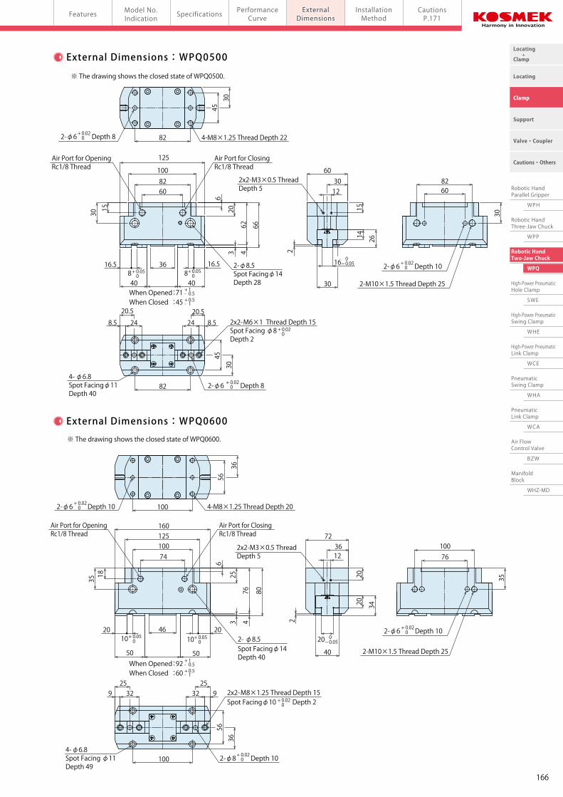
Locating +Clamp
Locating
Clamp
Cautions・Others
Support
Valve・Coupler
Robotic HandParallel Gripper
WPH
Robotic HandThree-Jaw Chuck
WPP
Robotic HandTwo-Jaw Chuck
WPQ
High-Power PneumaticHole Clamp
SWE
High-Power PneumaticSwing Clamp
WHE
High-Power PneumaticLink Clamp
WCE
PneumaticSwing Clamp
WHA
PneumaticLink Clamp
WCA
Air FlowControl Valve
BZW
ManifoldBlock
WHZ-MD
Pneumatic Robotic Hands Two-Jaw Chuck model WPQPerformanceCurve
Model No.Indication SpecificationsFeatures Installation
MethodCautionsP.171
ExternalDimensionsExternalDimensions
※ The drawing shows the closed state of WPQ0250.
※ The drawing shows the closed state of WPQ0400. ※ The drawing shows the closed state of WPQ0600.
2
18
424- φ4.2Spot Facing φ8 Depth 25
2-φ4 Depth 4
2- φ4.2Spot Facing φ8 Depth 13
64
1018 11
42
4138
21When Opened :34When Closed :22
When Opened :56When Closed :36
When Opened :71When Closed :45
When Opened :92When Closed :60
134
10.5
13
21
20
2x2- M4×0.7 Thread Depth 8Spot Facingφ6 Depth 2
4
10.5
27
3
42
52
28
Air Port for ClosingM5×0.8 Thread
4-M5×0.8 Thread Depth 12
27
18
20
42
18
8
10
18
6
12
36182x2-M3×0.5 Thread
Depth 4
2-φ4 Depth 4
18
2-M5×0.8 ThreadDepth 18
2-φ4 Depth 4
4
58 8
5
3
2-φ5 Depth 6
25
6650
2- φ6.8Spot Facingφ11Depth 25
58541625
100
66
1616
66
20
2-φ6 Depth 6
6
2538
4- φ5.1Spot Facingφ9 Depth 36
620 2x2- M6×1 Thread Depth12Spot Facingφ8 Depth 2
32
812 12
8
32
30
3 4
2-M8×1.25 ThreadDepth 20
14
27
23
122
2x2-M3×0.5 ThreadDepth 5
Air Port for ClosingRc1/8 Thread
4-M6×1 Thread Depth 1866
14
80
5
48
2-φ5 Depth 6
25
38
50
11
1225
82
45
30
4-M8×1.25 Thread Depth 222-φ6 Depth 8
6082100
125
15
30
6
203 4
62 66
40
16.58
36
408
16.5
Air Port for OpeningRc1/8 Thread
2- φ8.5Spot Facingφ14Depth 28
14 26
16
302
3012
15
2x2-M3×0.5 ThreadDepth 5
608260
30
2-φ6 Depth 10
2-M10×1.5 Thread Depth 25
82
45
30
8.5 24 8.524
20.5 20.5
4- φ6.8Spot Facingφ11 Depth 40
2-φ6 Depth 8
2x2- M6×1 Thread Depth 15Spot Facing φ8 Depth 2
2-φ6 Depth 10
100
4- φ6.8Spot Facing φ11 Depth 49
807643
4-M8×1.25 Thread Depth 20
36
2- φ8.5Spot Facingφ14 Depth 40
100
50
2x2- M8×1.25 Thread Depth 15Spot Facingφ10 Depth 2
25329
2-φ8 Depth 10
2010
925
32
36
56
50
46 2010
100125160Air Port for Opening
Rc1/8 Thread
3518
2-φ6 Depth 10
74
25
656
40
2
34
20
2020
72
12362x2-M3×0.5 Thread
Depth 5
2-M10×1.5 Thread Depth 25
76
35100
+ 0.02 0
+ 0.02 0
+ 0.02 0
+ 0.02 0
+ 0.05 0
+ 0.05 0
0- 0.05
+ 0.02 0
+ 0.02 0
+ 0.02 0
+ 0.02 0
+ 0.05 0
+ 0.05 0
0- 0.05
+ 0.02 0
+ 0.02 0
+ 0.02 0
+ 0.02 0
+ 0.05 0
+ 0.05 0
0- 0.05
+ 0.02 0
+ 0.02 0
+ 0.02 0
+ 0.02 0
+ 0.05 0
+ 0.05 0
0- 0.05
External Dimensions:WPQ0250
External Dimensions:WPQ0400
※ The drawing shows the closed state of WPQ0500.
External Dimensions:WPQ0500
External Dimensions:WPQ0600
Air Port for OpeningM5×0.8 Thread
Air Port for OpeningRc1/8 Thread
Air Port for ClosingRc1/8 Thread
Air Port for ClosingRc1/8 Thread
+ 1- 0.5+ 0.5- 1
+ 1- 0.5+ 0.5- 1
+ 1- 0.5+ 0.5- 1
+ 1- 0.5+ 0.5- 1
166
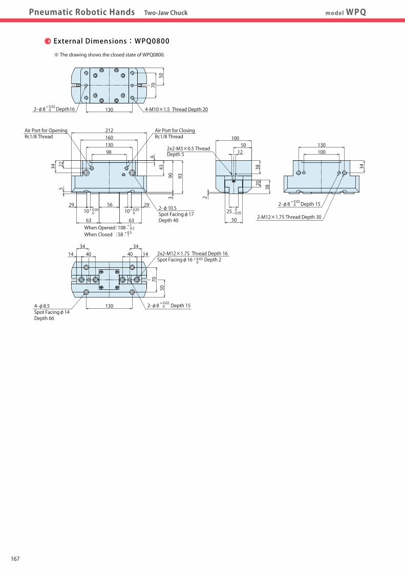
Locating +Clamp
Locating
Clamp
Cautions・Others
Support
Valve・Coupler
Robotic HandParallel Gripper
WPH
Robotic HandThree-Jaw Chuck
WPP
Robotic HandTwo-Jaw Chuck
WPQ
High-Power PneumaticHole Clamp
SWE
High-Power PneumaticSwing Clamp
WHE
High-Power PneumaticLink Clamp
WCE
PneumaticSwing Clamp
WHA
PneumaticLink Clamp
WCA
Air FlowControl Valve
BZW
ManifoldBlock
WHZ-MD
Pneumatic Robotic Hands Two-Jaw Chuck model WPQPerformanceCurve
Model No.Indication SpecificationsFeatures Installation
MethodCautionsP.171
ExternalDimensionsExternalDimensions
62
74
20
2210
52
101
32
102
90
80
2
20
106
20
732
100
110
122
1010
147
135
125
3213
20
1510
182
33
170
20
22
10
32
160
※ The drawing shows the closed state of WPQ0800.
External Dimensions:WPQ0800 External Dimensions:Proximity Switch for Gripping Detection
WPQ0250
WPQ0400
WPQ0500
WPQ0600
WPQ0800
Proximity Switch for Gripping DetectionJEP0000-P/P2(M8×1)
Proximity Switch for Gripping DetectionJEP0000-P(M8×1)
Proximity Switch for Gripping DetectionJEP0000-P(M8×1)
Proximity Switch for Gripping DetectionJEP0000-P(M8×1)
Proximity Switch for Gripping DetectionJEP0000-P(M8×1)
When Opened :108When Closed :58
2x2-M3×0.5 ThreadDepth 5
212
13098
2-φ8 Depth 15
130100
3438
12
90 93
43
6
34 22
Air Port for ClosingRc1/8 Thread
3434
4- φ8.5Spot Facingφ14 Depth 66
5070
2-φ8 Depth 15130
40 2x2- M12×1.75 Thread Depth 16Spot Facingφ16 Depth 2
14 1440
3
2- φ10.5Spot Facingφ17 Depth 40
5610
29
63 63
2910
5
50
252
38
20
2-M12×1.75 Thread Depth 30
130
50
4-M10×1.5 Thread Depth 20
70
160
2-φ8 Depth16
10050
+ 0.02 0
+ 0.02 0
+ 0.02 0
+ 0.02 0
+ 0.05 0
+ 0.05 0
0- 0.05
Air Port for OpeningRc1/8 Thread
+ 1- 0.5+ 0.5- 1
Note 1. Proximity Switch for Gripping Detection Type P2 (Length 16mm) cannot be installed in WPQ0400 or larger sizes.
167
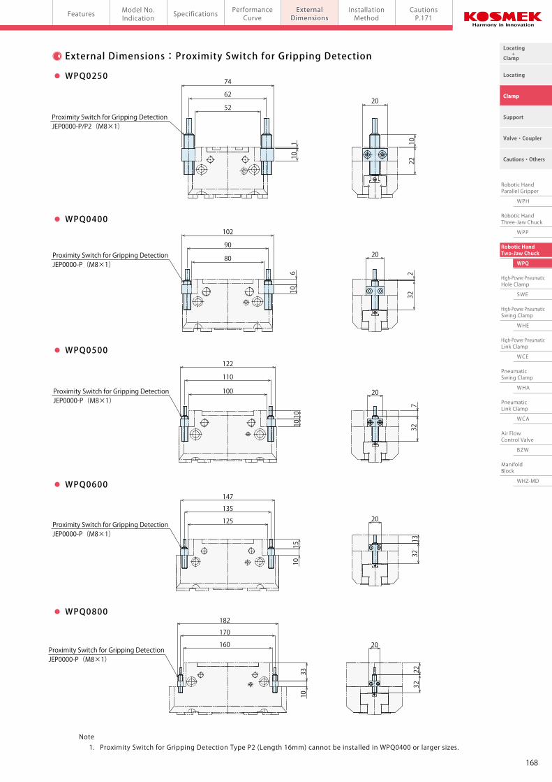
Locating +Clamp
Locating
Clamp
Cautions・Others
Support
Valve・Coupler
Robotic HandParallel Gripper
WPH
Robotic HandThree-Jaw Chuck
WPP
Robotic HandTwo-Jaw Chuck
WPQ
High-Power PneumaticHole Clamp
SWE
High-Power PneumaticSwing Clamp
WHE
High-Power PneumaticLink Clamp
WCE
PneumaticSwing Clamp
WHA
PneumaticLink Clamp
WCA
Air FlowControl Valve
BZW
ManifoldBlock
WHZ-MD
Pneumatic Robotic Hands Two-Jaw Chuck model WPQPerformanceCurve
Model No.Indication SpecificationsFeatures Installation
MethodCautionsP.171
ExternalDimensionsExternalDimensions
62
74
20
2210
52
101
32
102
90
80
2
20
106
20
732
100
110
122
1010
147
135
125
3213
20
1510
182
33
170
20
22
10
32
160
※ The drawing shows the closed state of WPQ0800.
External Dimensions:WPQ0800 External Dimensions:Proximity Switch for Gripping Detection
WPQ0250
WPQ0400
WPQ0500
WPQ0600
WPQ0800
Proximity Switch for Gripping DetectionJEP0000-P/P2(M8×1)
Proximity Switch for Gripping DetectionJEP0000-P(M8×1)
Proximity Switch for Gripping DetectionJEP0000-P(M8×1)
Proximity Switch for Gripping DetectionJEP0000-P(M8×1)
Proximity Switch for Gripping DetectionJEP0000-P(M8×1)
When Opened :108When Closed :58
2x2-M3×0.5 ThreadDepth 5
212
13098
2-φ8 Depth 15
130100
3438
12
90 93
43
6
34 22
Air Port for ClosingRc1/8 Thread
3434
4- φ8.5Spot Facingφ14 Depth 66
5070
2-φ8 Depth 15130
40 2x2- M12×1.75 Thread Depth 16Spot Facingφ16 Depth 2
14 1440
3
2- φ10.5Spot Facingφ17 Depth 40
5610
29
63 63
2910
5
50
25
2
38
20
2-M12×1.75 Thread Depth 30
130
50
4-M10×1.5 Thread Depth 20
70
160
2-φ8 Depth16
10050
+ 0.02 0
+ 0.02 0
+ 0.02 0
+ 0.02 0
+ 0.05 0
+ 0.05 0
0- 0.05
Air Port for OpeningRc1/8 Thread
+ 1- 0.5+ 0.5- 1
Note 1. Proximity Switch for Gripping Detection Type P2 (Length 16mm) cannot be installed in WPQ0400 or larger sizes.
168
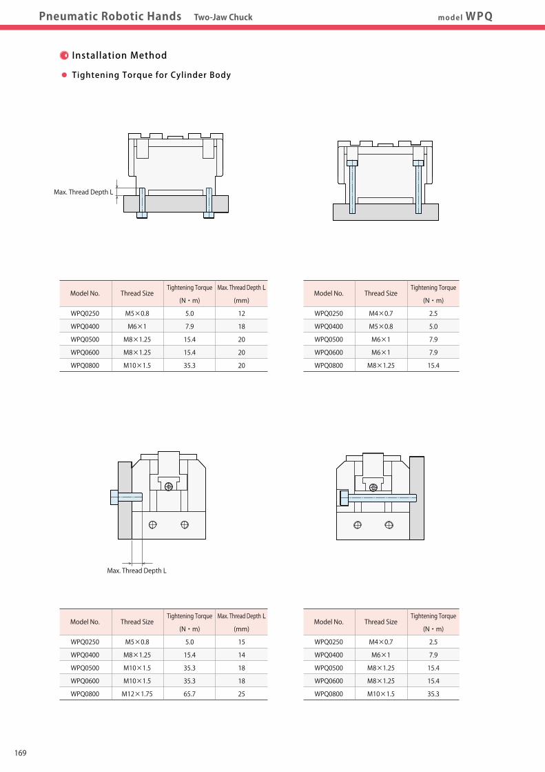
Locating +Clamp
Locating
Clamp
Cautions・Others
Support
Valve・Coupler
Robotic HandParallel Gripper
WPH
Robotic HandThree-Jaw Chuck
WPP
Robotic HandTwo-Jaw Chuck
WPQ
High-Power PneumaticHole Clamp
SWE
High-Power PneumaticSwing Clamp
WHE
High-Power PneumaticLink Clamp
WCE
PneumaticSwing Clamp
WHA
PneumaticLink Clamp
WCA
Air FlowControl Valve
BZW
ManifoldBlock
WHZ-MD
Pneumatic Robotic Hands Two-Jaw Chuck model WPQInstallationMethod
ExternalDimensions
InstallationMethod
PerformanceCurve
Model No.Indication SpecificationsFeatures Cautions
P.171
Installation Method
Hex. Wrench (1.5mm)
Dog Sensor
Max. Thread Depth L
Tightening Torque for Cylinder Body Tightening Torque for Gripper Installation Method for Dog Sensor
Model No.
WPQ0250
WPQ0400
WPQ0500
WPQ0600
WPQ0800
Thread Size
M5×0.8
M6×1
M8×1.25
M8×1.25
M10×1.5
Tightening Torque
(N・m)
5.0
7.9
15.4
15.4
35.3
Max. Thread Depth L
(mm)
12
18
20
20
20
Model No.
WPQ0250
WPQ0400
WPQ0500
WPQ0600
WPQ0800
Thread Size
M4×0.7
M6×1
M6×1
M8×1.25
M12×1.75
Tightening Torque
(N・m)
2.5
7.9
7.9
15.4
65.7
Max. Thread Depth L
(mm)
8
12
15
15
16
Model No.
WPQ0250
WPQ0400
WPQ0500
WPQ0600
WPQ0800
Thread Size
M5×0.8
M8×1.25
M10×1.5
M10×1.5
M12×1.75
Tightening Torque
(N・m)
5.0
15.4
35.3
35.3
65.7
Max. Thread Depth L
(mm)
15
14
18
18
25
Model No.
WPQ0250
WPQ0400
WPQ0500
WPQ0600
WPQ0800
Thread Size
M4×0.7
M6×1
M8×1.25
M8×1.25
M10×1.5
Tightening Torque
(N・m)
2.5
7.9
15.4
15.4
35.3
Model No.
WPQ0250
WPQ0400
WPQ0500
WPQ0600
WPQ0800
Thread Size
M4×0.7
M5×0.8
M6×1
M6×1
M8×1.25
Tightening Torque
(N・m)
2.5
5.0
7.9
7.9
15.4
Proximity Switch is used for opening and
closing detection of the cylinder.
Match the dog sensor to the detection position and
tighten it with the hexagon wrench (1.5mm).
Max. Thread Depth L
169
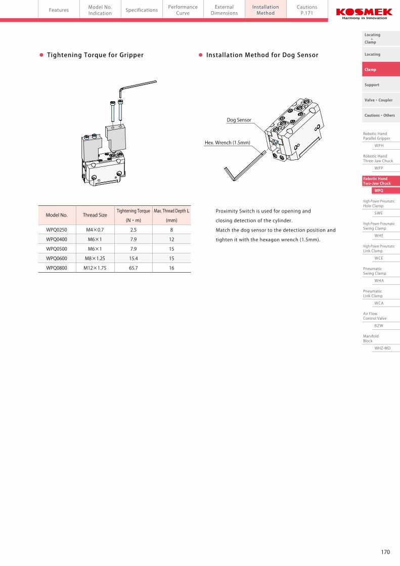
Locating +Clamp
Locating
Clamp
Cautions・Others
Support
Valve・Coupler
Robotic HandParallel Gripper
WPH
Robotic HandThree-Jaw Chuck
WPP
Robotic HandTwo-Jaw Chuck
WPQ
High-Power PneumaticHole Clamp
SWE
High-Power PneumaticSwing Clamp
WHE
High-Power PneumaticLink Clamp
WCE
PneumaticSwing Clamp
WHA
PneumaticLink Clamp
WCA
Air FlowControl Valve
BZW
ManifoldBlock
WHZ-MD
Pneumatic Robotic Hands Two-Jaw Chuck model WPQInstallationMethod
ExternalDimensions
InstallationMethod
PerformanceCurve
Model No.Indication SpecificationsFeatures Cautions
P.171
Installation Method
Hex. Wrench (1.5mm)
Dog Sensor
Max. Thread Depth L
Tightening Torque for Cylinder Body Tightening Torque for Gripper Installation Method for Dog Sensor
Model No.
WPQ0250
WPQ0400
WPQ0500
WPQ0600
WPQ0800
Thread Size
M5×0.8
M6×1
M8×1.25
M8×1.25
M10×1.5
Tightening Torque
(N・m)
5.0
7.9
15.4
15.4
35.3
Max. Thread Depth L
(mm)
12
18
20
20
20
Model No.
WPQ0250
WPQ0400
WPQ0500
WPQ0600
WPQ0800
Thread Size
M4×0.7
M6×1
M6×1
M8×1.25
M12×1.75
Tightening Torque
(N・m)
2.5
7.9
7.9
15.4
65.7
Max. Thread Depth L
(mm)
8
12
15
15
16
Model No.
WPQ0250
WPQ0400
WPQ0500
WPQ0600
WPQ0800
Thread Size
M5×0.8
M8×1.25
M10×1.5
M10×1.5
M12×1.75
Tightening Torque
(N・m)
5.0
15.4
35.3
35.3
65.7
Max. Thread Depth L
(mm)
15
14
18
18
25
Model No.
WPQ0250
WPQ0400
WPQ0500
WPQ0600
WPQ0800
Thread Size
M4×0.7
M6×1
M8×1.25
M8×1.25
M10×1.5
Tightening Torque
(N・m)
2.5
7.9
15.4
15.4
35.3
Model No.
WPQ0250
WPQ0400
WPQ0500
WPQ0600
WPQ0800
Thread Size
M4×0.7
M5×0.8
M6×1
M6×1
M8×1.25
Tightening Torque
(N・m)
2.5
5.0
7.9
7.9
15.4
Proximity Switch is used for opening and
closing detection of the cylinder.
Match the dog sensor to the detection position and
tighten it with the hexagon wrench (1.5mm).
Max. Thread Depth L
170
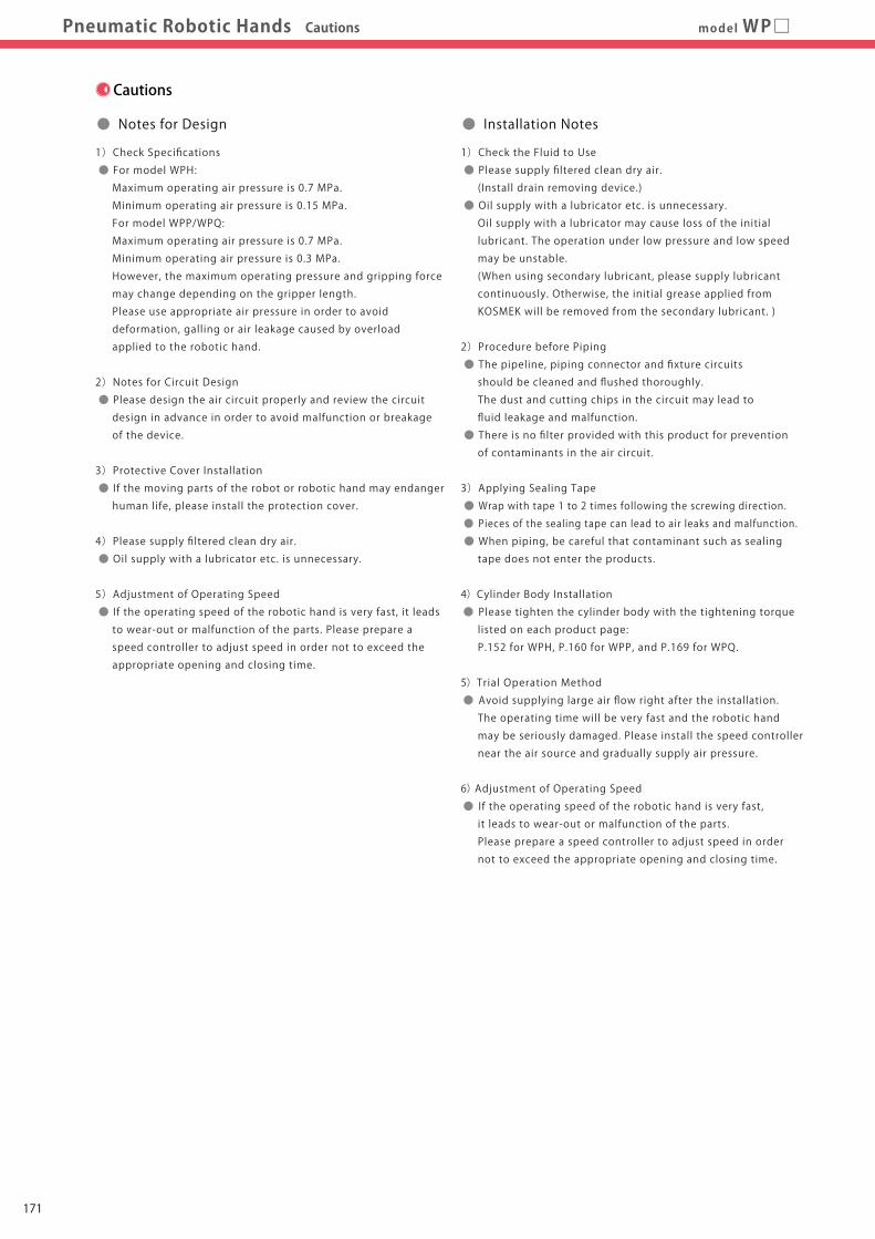
Locating +Clamp
Locating
Clamp
Cautions・Others
Support
Valve・Coupler
Robotic HandTwo-Jaw Chuck
WPQ
High-Power PneumaticHole Clamp
SWE
High-Power PneumaticSwing Clamp
WHE
High-Power PneumaticLink Clamp
WCE
PneumaticSwing Clamp
WHA
PneumaticLink Clamp
WCA
Air FlowControl Valve
BZW
ManifoldBlock
WHZ-MD
Robotic HandThree-Jaw Chuck
WPP
Robotic HandParallel Gripper
WPH
CautionsCautionsPneumatic Robotic Hands Cautions model WP□
Cautions
● Notes for Design
1)Check Specifications
● For model WPH:
Maximum operating air pressure is 0.7 MPa.
Minimum operating air pressure is 0.15 MPa.
For model WPP/WPQ:
Maximum operating air pressure is 0.7 MPa.
Minimum operating air pressure is 0.3 MPa.
However, the maximum operating pressure and gripping force
may change depending on the gripper length.
Please use appropriate air pressure in order to avoid
deformation, galling or air leakage caused by overload
applied to the robotic hand.
2)Notes for Circuit Design
● Please design the air circuit properly and review the circuit
design in advance in order to avoid malfunction or breakage
of the device.
3)Protective Cover Installation
● If the moving parts of the robot or robotic hand may endanger
human life, please install the protection cover.
4)Please supply filtered clean dry air.
● Oil supply with a lubricator etc. is unnecessary.
5)Adjustment of Operating Speed
● If the operating speed of the robotic hand is very fast, it leads
to wear-out or malfunction of the parts. Please prepare a
speed controller to adjust speed in order not to exceed the
appropriate opening and closing time.
1)Check the Fluid to Use
● Please supply filtered clean dry air.
(Install drain removing device.)
● Oil supply with a lubricator etc. is unnecessary.
Oil supply with a lubricator may cause loss of the initial
lubricant. The operation under low pressure and low speed
may be unstable.
(When using secondary lubricant, please supply lubricant
continuously. Otherwise, the initial grease applied from
KOSMEK will be removed from the secondary lubricant. )
2)Procedure before Piping
● The pipeline, piping connector and fixture circuits
should be cleaned and flushed thoroughly.
The dust and cutting chips in the circuit may lead to
fluid leakage and malfunction.
● There is no filter provided with this product for prevention
of contaminants in the air circuit.
3)Applying Sealing Tape
● Wrap with tape 1 to 2 times following the screwing direction.
● Pieces of the sealing tape can lead to air leaks and malfunction.
● When piping, be careful that contaminant such as sealing
tape does not enter the products.
4)Cylinder Body Installation
● Please tighten the cylinder body with the tightening torque
listed on each product page:
P.152 for WPH, P.160 for WPP, and P.169 for WPQ.
5)Trial Operation Method
● Avoid supplying large air flow right after the installation.
The operating time will be very fast and the robotic hand
may be seriously damaged. Please install the speed controller
near the air source and gradually supply air pressure.
6) Adjustment of Operating Speed
● If the operating speed of the robotic hand is very fast,
it leads to wear-out or malfunction of the parts.
Please prepare a speed controller to adjust speed in order
not to exceed the appropriate opening and closing time.
● Installation Notes ● Notes on Handling
1)It should be handled by qualified personnel.
● The hydraulic and pneumatic equipment should be handled
and maintained by qualified personnel.
2)Do not handle or remove the equipment unless safety
protocols are ensured.
① The machine and equipment can only be inspected or prepared
when it is confirmed that the preventive devices are in place.
② Before the machine is removed, make sure that the above-mentioned
safety measures are in place. Shut off the air of hydraulic source
and make sure no pressure exists in the hydraulic and air circuit.
③ After stopping the machine, do not remove until the equipment
cools down.
④ Make sure there is no abnormality in the bolts and respective
parts before restarting the machine or equipment.
3)In order to avoid injury, please do not touch the robotic hand
or robot while they are operating.
4)Do not disassemble or modify.
● If the equipment is taken apart or modified, the warranty
will be voided even within the warranty period.
・ Maintenance/Inspection ・ Warranty※ Please refer to P.363 for common cautions.
171
Locating +Clamp
Locating
Clamp
Cautions・Others
Support
Valve・Coupler
Robotic HandTwo-Jaw Chuck
WPQ
High-Power PneumaticHole Clamp
SWE
High-Power PneumaticSwing Clamp
WHE
High-Power PneumaticLink Clamp
WCE
PneumaticSwing Clamp
WHA
PneumaticLink Clamp
WCA
Air FlowControl Valve
BZW
ManifoldBlock
WHZ-MD
Robotic HandThree-Jaw Chuck
WPP
Robotic HandParallel Gripper
WPH
CautionsCautionsPneumatic Robotic Hands Cautions model WP□
Cautions
● Notes for Design
1)Check Specifications
● For model WPH:
Maximum operating air pressure is 0.7 MPa.
Minimum operating air pressure is 0.15 MPa.
For model WPP/WPQ:
Maximum operating air pressure is 0.7 MPa.
Minimum operating air pressure is 0.3 MPa.
However, the maximum operating pressure and gripping force
may change depending on the gripper length.
Please use appropriate air pressure in order to avoid
deformation, galling or air leakage caused by overload
applied to the robotic hand.
2)Notes for Circuit Design
● Please design the air circuit properly and review the circuit
design in advance in order to avoid malfunction or breakage
of the device.
3)Protective Cover Installation
● If the moving parts of the robot or robotic hand may endanger
human life, please install the protection cover.
4)Please supply filtered clean dry air.
● Oil supply with a lubricator etc. is unnecessary.
5)Adjustment of Operating Speed
● If the operating speed of the robotic hand is very fast, it leads
to wear-out or malfunction of the parts. Please prepare a
speed controller to adjust speed in order not to exceed the
appropriate opening and closing time.
1)Check the Fluid to Use
● Please supply filtered clean dry air.
(Install drain removing device.)
● Oil supply with a lubricator etc. is unnecessary.
Oil supply with a lubricator may cause loss of the initial
lubricant. The operation under low pressure and low speed
may be unstable.
(When using secondary lubricant, please supply lubricant
continuously. Otherwise, the initial grease applied from
KOSMEK will be removed from the secondary lubricant. )
2)Procedure before Piping
● The pipeline, piping connector and fixture circuits
should be cleaned and flushed thoroughly.
The dust and cutting chips in the circuit may lead to
fluid leakage and malfunction.
● There is no filter provided with this product for prevention
of contaminants in the air circuit.
3)Applying Sealing Tape
● Wrap with tape 1 to 2 times following the screwing direction.
● Pieces of the sealing tape can lead to air leaks and malfunction.
● When piping, be careful that contaminant such as sealing
tape does not enter the products.
4)Cylinder Body Installation
● Please tighten the cylinder body with the tightening torque
listed on each product page:
P.152 for WPH, P.160 for WPP, and P.169 for WPQ.
5)Trial Operation Method
● Avoid supplying large air flow right after the installation.
The operating time will be very fast and the robotic hand
may be seriously damaged. Please install the speed controller
near the air source and gradually supply air pressure.
6) Adjustment of Operating Speed
● If the operating speed of the robotic hand is very fast,
it leads to wear-out or malfunction of the parts.
Please prepare a speed controller to adjust speed in order
not to exceed the appropriate opening and closing time.
● Installation Notes ● Notes on Handling
1)It should be handled by qualified personnel.
● The hydraulic and pneumatic equipment should be handled
and maintained by qualified personnel.
2)Do not handle or remove the equipment unless safety
protocols are ensured.
① The machine and equipment can only be inspected or prepared
when it is confirmed that the preventive devices are in place.
② Before the machine is removed, make sure that the above-mentioned
safety measures are in place. Shut off the air of hydraulic source
and make sure no pressure exists in the hydraulic and air circuit.
③ After stopping the machine, do not remove until the equipment
cools down.
④ Make sure there is no abnormality in the bolts and respective
parts before restarting the machine or equipment.
3)In order to avoid injury, please do not touch the robotic hand
or robot while they are operating.
4)Do not disassemble or modify.
● If the equipment is taken apart or modified, the warranty
will be voided even within the warranty period.
・ Maintenance/Inspection ・ Warranty※ Please refer to P.363 for common cautions.
172
Locating +Clamp
Locating
Clamp
Cautions・Others
Support
Valve・Coupler
Robotic HandTwo-Jaw Chuck
WPQ
High-Power PneumaticHole Clamp
SWE
High-Power PneumaticSwing Clamp
WHE
High-Power PneumaticLink Clamp
WCE
PneumaticSwing Clamp
WHA
PneumaticLink Clamp
WCA
Air FlowControl Valve
BZW
ManifoldBlock
WHZ-MD
Robotic HandThree-Jaw Chuck
WPP
Robotic HandParallel Gripper
WPH
Application Table ExternalDimensions
ElectricCircuit DiagramSpecificationsApplication Table SpecificationsModel No.
IndicationModel No.Indication
ElectricCircuit Diagram
ExternalDimensions
CautionsP.177Pneumatic Robotic Hands Auto Switch / Proximity Switch model JEP
Model No. Indication
Application Table
2 31
JEP 000 0 - A1 L
1 Design No.
0 : Revision Number
3 Electric Cable Length ※1
Blank : 1m L : 3m
2 Switch Type
A1 : 2-Wire Reed Auto Switch A2 : 2-Wire Reed Auto Switch B1 : 3-Wire Solid State Auto Switch B2 : 3-Wire Solid State Auto Switch P : 3-Wire Proximity Switch for Gripping Detection (Length 32mm)
P2 : 3-Wire Proximity Switch for Gripping Detection (Length 16mm)
Switch Type
Model No.
WPH0100
WPH0160
WPH0200
WPP0300
WPP0400
WPP0500
WPP0600
WPP0800
WPQ0250
WPQ0400
WPQ0500
WPQ0600
WPQ0800
2-Wire Reed Auto Switch 3-Wire Solid State Auto Switch 3-Wire Proximity Switch for Gripping Detection
JEP0000-A1□
●
JEP0000-A2□
●
●
JEP0000-B1□
●
JEP0000-B2□
●
●
JEP0000-P
●
●
●
●
●
●
●
●
●
●
JEP0000-P2
●
●
●
●
●
●
Note ※1. Electric Cable Length is chosen only for A□/B□ Auto Switch of Switch Type. For P□: Proximity Switch for Gripping Detection, electric cable length is all 2m.
3 2
JEP0000-A□□ (2-Wire Reed Auto Switch)
Specifications
Electric Circuit Diagram
External Dimensions:JEP0000-A1□
External Dimensions:JEP0000-A2□
Model No. JEP0000-A1 JEP0000-A1L JEP0000-A2 JEP0000-A2L
Name Reed Auto Switch
Wiring Type 2-Wire
Applicable Load Relay, Programmable Logic Controller (PLC)
Less than DC24V / 40mA Load Voltage / Load Current Less than AC100V / 20mA
Internal Voltage Drop Less than 3V
Operating Time 1ms
Ambient Temperature -10~70℃
Withstand Voltage AC1500V (There should be no abnormalities in 1 min. application.)
Leakage Current 0
Shock Resistance 30G
Enclosure Rating IP67 (IEC Standard)
Protection Circuit None
Indicator Light Red LED illuminates when turned ON
Electric Cable Length 1m 3m 1m 3m
LED
ZD
Reed Switch
(+)
(-)
4.92.8
φ4
25
2
LED Indicator
Brown Cable (+)
Blue Cable (-)
M2.5×0.45 Mounting Bolt
5
3.7
4.8
6.2
26
2
LED Indicator
Brown Cable (+)
Blue Cable (-)
M2.5×0.45 Mounting Bolt
173
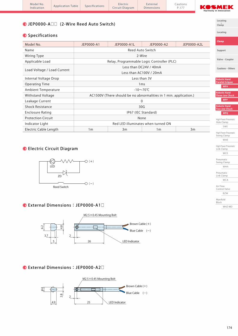
Locating +Clamp
Locating
Clamp
Cautions・Others
Support
Valve・Coupler
Robotic HandTwo-Jaw Chuck
WPQ
High-Power PneumaticHole Clamp
SWE
High-Power PneumaticSwing Clamp
WHE
High-Power PneumaticLink Clamp
WCE
PneumaticSwing Clamp
WHA
PneumaticLink Clamp
WCA
Air FlowControl Valve
BZW
ManifoldBlock
WHZ-MD
Robotic HandThree-Jaw Chuck
WPP
Robotic HandParallel Gripper
WPH
Application Table ExternalDimensions
ElectricCircuit DiagramSpecificationsApplication Table SpecificationsModel No.
IndicationModel No.Indication
ElectricCircuit Diagram
ExternalDimensions
CautionsP.177Pneumatic Robotic Hands Auto Switch / Proximity Switch model JEP
Model No. Indication
Application Table
2 31
JEP 000 0 - A1 L
1 Design No.
0 : Revision Number
3 Electric Cable Length ※1
Blank : 1m L : 3m
2 Switch Type
A1 : 2-Wire Reed Auto Switch A2 : 2-Wire Reed Auto Switch B1 : 3-Wire Solid State Auto Switch B2 : 3-Wire Solid State Auto Switch P : 3-Wire Proximity Switch for Gripping Detection (Length 32mm)
P2 : 3-Wire Proximity Switch for Gripping Detection (Length 16mm)
Switch Type
Model No.
WPH0100
WPH0160
WPH0200
WPP0300
WPP0400
WPP0500
WPP0600
WPP0800
WPQ0250
WPQ0400
WPQ0500
WPQ0600
WPQ0800
2-Wire Reed Auto Switch 3-Wire Solid State Auto Switch 3-Wire Proximity Switch for Gripping Detection
JEP0000-A1□
●
JEP0000-A2□
●
●
JEP0000-B1□
●
JEP0000-B2□
●
●
JEP0000-P
●
●
●
●
●
●
●
●
●
●
JEP0000-P2
●
●
●
●
●
●
Note ※1. Electric Cable Length is chosen only for A□/B□ Auto Switch of Switch Type. For P□: Proximity Switch for Gripping Detection, electric cable length is all 2m.
3 2
JEP0000-A□□ (2-Wire Reed Auto Switch)
Specifications
Electric Circuit Diagram
External Dimensions:JEP0000-A1□
External Dimensions:JEP0000-A2□
Model No. JEP0000-A1 JEP0000-A1L JEP0000-A2 JEP0000-A2L
Name Reed Auto Switch
Wiring Type 2-Wire
Applicable Load Relay, Programmable Logic Controller (PLC)
Less than DC24V / 40mA Load Voltage / Load Current Less than AC100V / 20mA
Internal Voltage Drop Less than 3V
Operating Time 1ms
Ambient Temperature -10~70℃
Withstand Voltage AC1500V (There should be no abnormalities in 1 min. application.)
Leakage Current 0
Shock Resistance 30G
Enclosure Rating IP67 (IEC Standard)
Protection Circuit None
Indicator Light Red LED illuminates when turned ON
Electric Cable Length 1m 3m 1m 3m
LED
ZD
Reed Switch
(+)
(-)
4.9
2.8
φ4
25
2
LED Indicator
Brown Cable (+)
Blue Cable (-)
M2.5×0.45 Mounting Bolt
5
3.7
4.8
6.2
26
2
LED Indicator
Brown Cable (+)
Blue Cable (-)
M2.5×0.45 Mounting Bolt
174
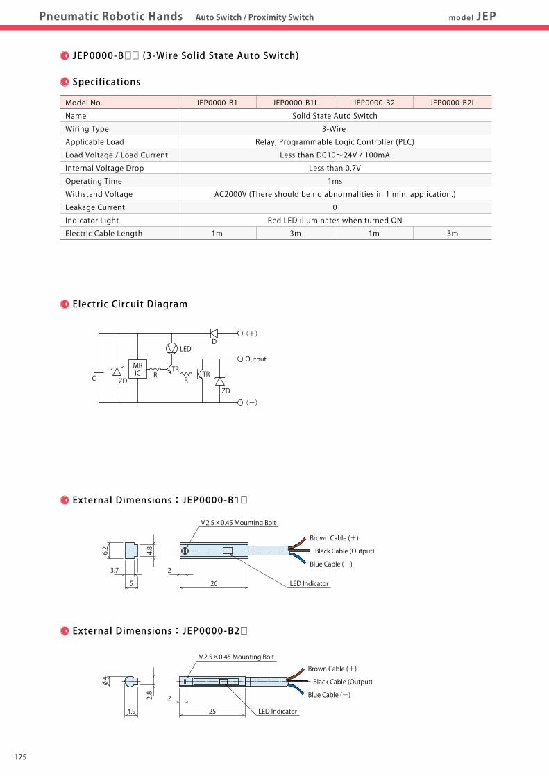
Locating +Clamp
Locating
Clamp
Cautions・Others
Support
Valve・Coupler
Robotic HandTwo-Jaw Chuck
WPQ
High-Power PneumaticHole Clamp
SWE
High-Power PneumaticSwing Clamp
WHE
High-Power PneumaticLink Clamp
WCE
PneumaticSwing Clamp
WHA
PneumaticLink Clamp
WCA
Air FlowControl Valve
BZW
ManifoldBlock
WHZ-MD
Robotic HandThree-Jaw Chuck
WPP
Robotic HandParallel Gripper
WPH
Pneumatic Robotic Hands Auto Switch / Proximity Switch model JEP Application TableModel No.Indication
CautionsP.177
ExternalDimensions
ElectricCircuit DiagramSpecificationsSpecifications ElectricCircuit Diagram
ExternalDimensions
JEP0000-P□ (3-Wire Proximity Switch for Gripping Detection)
Specifications
Electric Circuit Diagram
External Dimensions:JEP0000-P
External Dimensions:JEP0000-P2
Model No. JEP0000-P EP0000-P2
Name Proximity Switch for Gripping Detection
Wiring Type 3-Wire
Output Type NPN
Moving Distance 1.5±0.15mm
Voltage Range DC10~30V
Opening / Closing Voltage Less than 200mA
Current Consumption Less than 10mA
Response Frequency 800Hz
Ambient Temperature -25~70℃
Withstand Voltage AC2000V (There should be no abnormalities in 1 min. application.)
Indicator Light Red LED illuminates when turned ON
Electric Cable Length 2m
Model No. JEP0000-B1 JEP0000-B1L JEP0000-B2 JEP0000-B2L
Name Solid State Auto Switch
Wiring Type 3-Wire
Applicable Load Relay, Programmable Logic Controller (PLC)
Load Voltage / Load Current Less than DC10~24V / 100mA
Internal Voltage Drop Less than 0.7V
Operating Time 1ms
Withstand Voltage AC2000V (There should be no abnormalities in 1 min. application.)
Leakage Current 0
Indicator Light Red LED illuminates when turned ON
Electric Cable Length 1m 3m 1m 3m
32
Brown Cable (+)
Blue Cable (-)
M8×1 Thread
JEP0000-B□□ (3-Wire Solid State Auto Switch)
Specifications
Electric Circuit Diagram
External Dimensions:JEP0000-B1□
External Dimensions:JEP0000-B2□
4.9
2.8
φ4
25
2
LED Indicator
Brown Cable (+)
Blue Cable (-)
M2.5×0.45 Mounting Bolt
5
3.7
4.8
6.2
26
2
LED Indicator
Brown Cable (+)
Black Cable (Output)Black Cable (Output)
16
Brown Cable (+)
Blue Cable (-)
M8×1 Thread
Black Cable (Output)Black Cable (Output)
Blue Cable (-)
M2.5×0.45 Mounting Bolt
LED
ZDZD
RMRIC
C R
D
TRTR
(+)
(-)
Output
Brown
Load
Main Circuit of Proximity Sensor
Blue
10K
2Ω
(+)
(-)
175
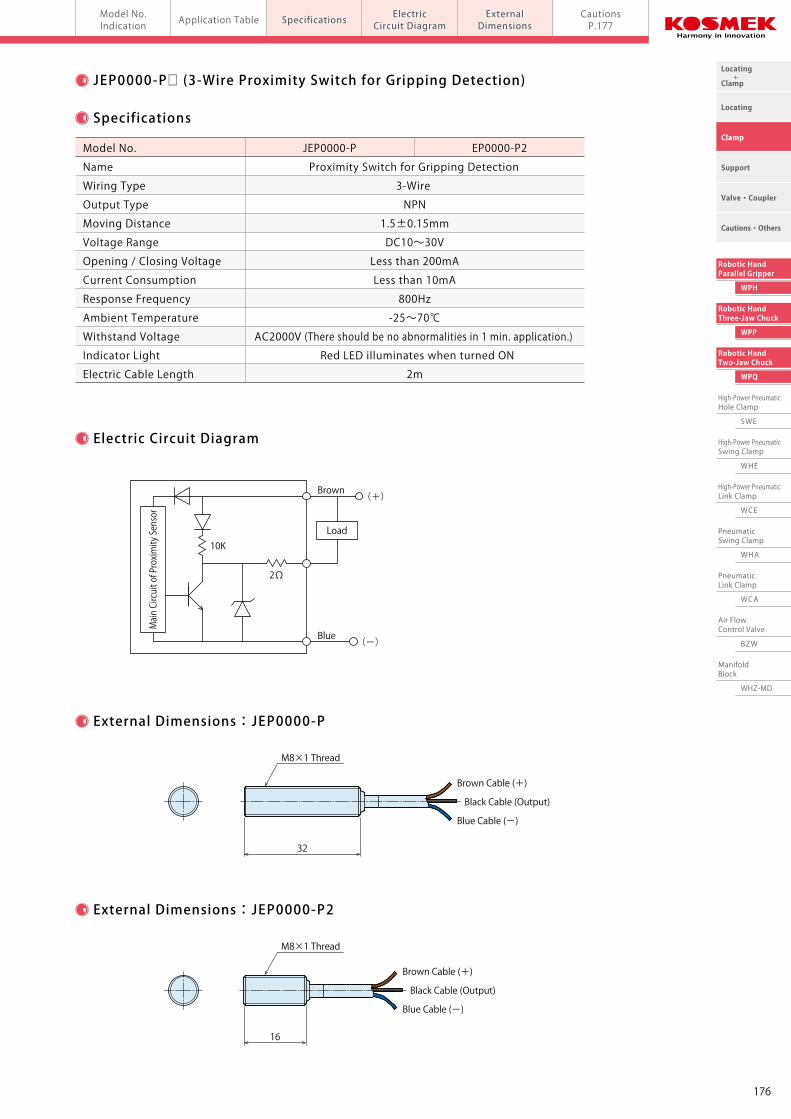
Locating +Clamp
Locating
Clamp
Cautions・Others
Support
Valve・Coupler
Robotic HandTwo-Jaw Chuck
WPQ
High-Power PneumaticHole Clamp
SWE
High-Power PneumaticSwing Clamp
WHE
High-Power PneumaticLink Clamp
WCE
PneumaticSwing Clamp
WHA
PneumaticLink Clamp
WCA
Air FlowControl Valve
BZW
ManifoldBlock
WHZ-MD
Robotic HandThree-Jaw Chuck
WPP
Robotic HandParallel Gripper
WPH
Pneumatic Robotic Hands Auto Switch / Proximity Switch model JEP Application TableModel No.Indication
CautionsP.177
ExternalDimensions
ElectricCircuit DiagramSpecificationsSpecifications ElectricCircuit Diagram
ExternalDimensions
JEP0000-P□ (3-Wire Proximity Switch for Gripping Detection)
Specifications
Electric Circuit Diagram
External Dimensions:JEP0000-P
External Dimensions:JEP0000-P2
Model No. JEP0000-P EP0000-P2
Name Proximity Switch for Gripping Detection
Wiring Type 3-Wire
Output Type NPN
Moving Distance 1.5±0.15mm
Voltage Range DC10~30V
Opening / Closing Voltage Less than 200mA
Current Consumption Less than 10mA
Response Frequency 800Hz
Ambient Temperature -25~70℃
Withstand Voltage AC2000V (There should be no abnormalities in 1 min. application.)
Indicator Light Red LED illuminates when turned ON
Electric Cable Length 2m
Model No. JEP0000-B1 JEP0000-B1L JEP0000-B2 JEP0000-B2L
Name Solid State Auto Switch
Wiring Type 3-Wire
Applicable Load Relay, Programmable Logic Controller (PLC)
Load Voltage / Load Current Less than DC10~24V / 100mA
Internal Voltage Drop Less than 0.7V
Operating Time 1ms
Withstand Voltage AC2000V (There should be no abnormalities in 1 min. application.)
Leakage Current 0
Indicator Light Red LED illuminates when turned ON
Electric Cable Length 1m 3m 1m 3m
32
Brown Cable (+)
Blue Cable (-)
M8×1 Thread
JEP0000-B□□ (3-Wire Solid State Auto Switch)
Specifications
Electric Circuit Diagram
External Dimensions:JEP0000-B1□
External Dimensions:JEP0000-B2□
4.9
2.8
φ4
25
2
LED Indicator
Brown Cable (+)
Blue Cable (-)
M2.5×0.45 Mounting Bolt
5
3.7
4.8
6.2
26
2
LED Indicator
Brown Cable (+)
Black Cable (Output)Black Cable (Output)
16
Brown Cable (+)
Blue Cable (-)
M8×1 Thread
Black Cable (Output)Black Cable (Output)
Blue Cable (-)
M2.5×0.45 Mounting Bolt
LED
ZDZD
RMRIC
C R
D
TRTR
(+)
(-)
Output
Brown
Load
Main Circuit of Proximity Sensor
Blue
10K
2Ω
(+)
(-)
176
Locating +Clamp
Locating
Clamp
Cautions・Others
Support
Valve・Coupler
Robotic HandTwo-Jaw Chuck
WPQ
High-Power PneumaticHole Clamp
SWE
High-Power PneumaticSwing Clamp
WHE
High-Power PneumaticLink Clamp
WCE
PneumaticSwing Clamp
WHA
PneumaticLink Clamp
WCA
Air FlowControl Valve
BZW
ManifoldBlock
WHZ-MD
Robotic HandThree-Jaw Chuck
WPP
Robotic HandParallel Gripper
WPH
CautionsCautionsPneumatic Robotic Hands Auto Switch / Proximity Switch Cautions model JEP
Cautions
● Notes for Design
1)Check the Specifications
● Please use each product according to the specifications.
The product may be damaged or malfunction if used
outside the range of load or specifications.
2)Notes on Use in the Interlock Circuit
● When the auto switch is used for an interlock signal that requires
high reliability, please use a double interlock system by providing
a mechanical protection function. Or by using another switch
(sensor) together with the auto switch. Also, please perform
periodic maintenance and confirm proper operation.
3)Wiring should be prepared as short as possible.
● For the reed auto switch, if the wiring length to the load is
longer, inrush current to the auto switch increases and
the life span will be shortened. (Remains ON)
● If the wiring length of the solid state auto switch is long,
we recommend installing the ferrite core on both ends
of the electric cable for noise control.
4)Please avoid using loads that generate surge voltage.
● If driving loads that generate surge voltage such as relay,
please use the auto switch equipped with junction protective
circuit or install protective box.
● If surge voltage is repeatedly applied to the auto switch even
with the Zener Diode for surge protection, it may damage
the contact. When directly driving loads generating
surge voltage, such as solenoid valves, use the auto switch
equipped with surge absorption element.
● The magnet switch is equipped with surge absorption element.
However, please provide an absorption element, such as
varistor, if there is large surge-generating equipment.
Example: Motors or welding machines.
5)Leakage Current
● In case of 2-wire solid state auto switch, the leakage current
that activates internal circuit of the auto switch may flow even
in OFF state. If the load operating current (the controller is in
OFF state) does not satisfy the specified leakage current,
it may result in restoration defect (remains ON state).
If it does not satisfy the specifications, please use 3-wire auto
switch. Also, n parallel connections will multiply leakage
current flowing to the load by n times.
6)Internal Voltage Drop of the Auto Switch
● Due to voltage drop (refer to internal voltage drop on the
specifications) caused by internal resistance of LED, voltage
drop of n auto switches connected in series will be multiplied
by n times.
As a result, in some cases the load will not activate even if
the auto switch drives properly.
7)When wiring is disconnected, or when forcibly activating the
auto switch for action confirmation, carefully design the circuit
to avoid reverse current.
● The auto switch may malfunction or be damaged when
reverse current occurs.
8)When multiple cylinders or robotic hands are placed
close together.
● Please provide enough space when using multiple actuators
such as cylinders or robotic hands equipped with auto switches.
(If allowable distance of each actuator is specified please
follow specified instructions.) If they are too close,
auto switches may malfunction due to magnetic interference.
9)Secure space for maintenance and inspection
● Please secure space for maintenance and inspection of auto
switches when setting actuators such as cylinders and robotic
hands equipped with auto switches.
● Notes on Operating Environment ● Installation Notes
1)Never use the product in an atmosphere with explosive gases.
● Auto switches are not designed to prevent explosion. Do not
use the product in an atmosphere with explosive gases since
it may cause serious explosions.
2)Do not use the product in an area where a magnetic field is
generated.
● Auto switches may malfunction, or internal magnet actuators,
such as cylinders or robotic hands, equipped with auto switches
will be demagnetized.
3)Do not use the product in an environment where the auto
switches are continuously exposed to water or coolant.
● Although IEC standard IP67 structure is satisfied, please avoid
using auto switches in an environment where continuously
exposed to water or coolant. This may cause insulation
failure or malfunction.
4)Do not use the product in an environment with oil or chemicals.
● If auto switches are used in an environment with coolant or
cleaning solvent, even in a short time, they may be adversely
affected by improper insulation, malfunction due to swelling
of potting resin and or hardening of electric cable.
5)Do not use the product in an environment subject to large
temperature cycle.
● Heat cycles other than ordinary changes in temperature may
adversely affect the internal structure of auto switches.
6)Avoid accumulation of steel dust and close connection of
magnetic materials.
● An amount of steel chips or steel dusts, such as sputters
of welding accumulate around an actuator. Cylinders, robotic
hand equipped with auto switches and or magnetic materials
(those attracted by magnet) are gathered closely to
the actuator. These can weaken internal magnet actuators.
7)Do not use the product in an environment with excessive impact.
● Under the condition of the excessive impact of more than 30G,
the contact of the reed auto switch will malfunction and
the indicator light may signal or may be disconnected.
1)Do not drop or bump.
● Do not drop, bump or apply excessive impact on auto switches.
The auto switches may be damaged and cause malfunction.
2)Tighten auto switches with appropriate tightening torque.
● Please follow the tightening torque below.
Excessive tightening torque may damage the screw, fitting
or main body of the auto switches.
Also, mounting position may be shifted with insufficient
tightening torque.
3)Do not carry cylinders or robotic hands by holding the
electric cables of auto switches.
● It may break the electric cable or damage the internal element.
4)Do not fix auto switches with the screws other than
attached in main body of the auto switches.
● Using non-designated screws may damage auto switches.
5)Install the auto switches at the center of the operating area.
● Mounting position of auto switches should be adjusted so that
a detected object (piston etc.) stops at the center of operating
range. (Mounting position shown in the catalog shows the
most suitable fixed position of stroke end.) Please refer to
P.151 for WPH, P.159 for WPP and P.168 for WPQ.
If the auto switches are mounted at the edge of operating range
(near the boundary of ON and OFF), output movement may be
unstable.
6)Mounting position of the auto switches should be adjusted
by checking actual operating state.
● Depending on the installation environment, actuators such
as cylinders and robotic hands may not operate properly
even if they are mounted to the appropriate position.
Make sure to check the operating condition even when
mounting them at the middle of the stroke.
Tightening Torque(N・m)
0.1
0.25
0.5
Screw Size
M2×0.4
M2.5×0.45
M3×0.5
177
Locating +Clamp
Locating
Clamp
Cautions・Others
Support
Valve・Coupler
Robotic HandTwo-Jaw Chuck
WPQ
High-Power PneumaticHole Clamp
SWE
High-Power PneumaticSwing Clamp
WHE
High-Power PneumaticLink Clamp
WCE
PneumaticSwing Clamp
WHA
PneumaticLink Clamp
WCA
Air FlowControl Valve
BZW
ManifoldBlock
WHZ-MD
Robotic HandThree-Jaw Chuck
WPP
Robotic HandParallel Gripper
WPH
CautionsCautionsPneumatic Robotic Hands Auto Switch / Proximity Switch Cautions model JEP
Cautions
● Notes for Design
1)Check the Specifications
● Please use each product according to the specifications.
The product may be damaged or malfunction if used
outside the range of load or specifications.
2)Notes on Use in the Interlock Circuit
● When the auto switch is used for an interlock signal that requires
high reliability, please use a double interlock system by providing
a mechanical protection function. Or by using another switch
(sensor) together with the auto switch. Also, please perform
periodic maintenance and confirm proper operation.
3)Wiring should be prepared as short as possible.
● For the reed auto switch, if the wiring length to the load is
longer, inrush current to the auto switch increases and
the life span will be shortened. (Remains ON)
● If the wiring length of the solid state auto switch is long,
we recommend installing the ferrite core on both ends
of the electric cable for noise control.
4)Please avoid using loads that generate surge voltage.
● If driving loads that generate surge voltage such as relay,
please use the auto switch equipped with junction protective
circuit or install protective box.
● If surge voltage is repeatedly applied to the auto switch even
with the Zener Diode for surge protection, it may damage
the contact. When directly driving loads generating
surge voltage, such as solenoid valves, use the auto switch
equipped with surge absorption element.
● The magnet switch is equipped with surge absorption element.
However, please provide an absorption element, such as
varistor, if there is large surge-generating equipment.
Example: Motors or welding machines.
5)Leakage Current
● In case of 2-wire solid state auto switch, the leakage current
that activates internal circuit of the auto switch may flow even
in OFF state. If the load operating current (the controller is in
OFF state) does not satisfy the specified leakage current,
it may result in restoration defect (remains ON state).
If it does not satisfy the specifications, please use 3-wire auto
switch. Also, n parallel connections will multiply leakage
current flowing to the load by n times.
6)Internal Voltage Drop of the Auto Switch
● Due to voltage drop (refer to internal voltage drop on the
specifications) caused by internal resistance of LED, voltage
drop of n auto switches connected in series will be multiplied
by n times.
As a result, in some cases the load will not activate even if
the auto switch drives properly.
7)When wiring is disconnected, or when forcibly activating the
auto switch for action confirmation, carefully design the circuit
to avoid reverse current.
● The auto switch may malfunction or be damaged when
reverse current occurs.
8)When multiple cylinders or robotic hands are placed
close together.
● Please provide enough space when using multiple actuators
such as cylinders or robotic hands equipped with auto switches.
(If allowable distance of each actuator is specified please
follow specified instructions.) If they are too close,
auto switches may malfunction due to magnetic interference.
9)Secure space for maintenance and inspection
● Please secure space for maintenance and inspection of auto
switches when setting actuators such as cylinders and robotic
hands equipped with auto switches.
● Notes on Operating Environment ● Installation Notes
1)Never use the product in an atmosphere with explosive gases.
● Auto switches are not designed to prevent explosion. Do not
use the product in an atmosphere with explosive gases since
it may cause serious explosions.
2)Do not use the product in an area where a magnetic field is
generated.
● Auto switches may malfunction, or internal magnet actuators,
such as cylinders or robotic hands, equipped with auto switches
will be demagnetized.
3)Do not use the product in an environment where the auto
switches are continuously exposed to water or coolant.
● Although IEC standard IP67 structure is satisfied, please avoid
using auto switches in an environment where continuously
exposed to water or coolant. This may cause insulation
failure or malfunction.
4)Do not use the product in an environment with oil or chemicals.
● If auto switches are used in an environment with coolant or
cleaning solvent, even in a short time, they may be adversely
affected by improper insulation, malfunction due to swelling
of potting resin and or hardening of electric cable.
5)Do not use the product in an environment subject to large
temperature cycle.
● Heat cycles other than ordinary changes in temperature may
adversely affect the internal structure of auto switches.
6)Avoid accumulation of steel dust and close connection of
magnetic materials.
● An amount of steel chips or steel dusts, such as sputters
of welding accumulate around an actuator. Cylinders, robotic
hand equipped with auto switches and or magnetic materials
(those attracted by magnet) are gathered closely to
the actuator. These can weaken internal magnet actuators.
7)Do not use the product in an environment with excessive impact.
● Under the condition of the excessive impact of more than 30G,
the contact of the reed auto switch will malfunction and
the indicator light may signal or may be disconnected.
1)Do not drop or bump.
● Do not drop, bump or apply excessive impact on auto switches.
The auto switches may be damaged and cause malfunction.
2)Tighten auto switches with appropriate tightening torque.
● Please follow the tightening torque below.
Excessive tightening torque may damage the screw, fitting
or main body of the auto switches.
Also, mounting position may be shifted with insufficient
tightening torque.
3)Do not carry cylinders or robotic hands by holding the
electric cables of auto switches.
● It may break the electric cable or damage the internal element.
4)Do not fix auto switches with the screws other than
attached in main body of the auto switches.
● Using non-designated screws may damage auto switches.
5)Install the auto switches at the center of the operating area.
● Mounting position of auto switches should be adjusted so that
a detected object (piston etc.) stops at the center of operating
range. (Mounting position shown in the catalog shows the
most suitable fixed position of stroke end.) Please refer to
P.151 for WPH, P.159 for WPP and P.168 for WPQ.
If the auto switches are mounted at the edge of operating range
(near the boundary of ON and OFF), output movement may be
unstable.
6)Mounting position of the auto switches should be adjusted
by checking actual operating state.
● Depending on the installation environment, actuators such
as cylinders and robotic hands may not operate properly
even if they are mounted to the appropriate position.
Make sure to check the operating condition even when
mounting them at the middle of the stroke.
Tightening Torque(N・m)
0.1
0.25
0.5
Screw Size
M2×0.4
M2.5×0.45
M3×0.5
178
Locating +Clamp
Locating
Clamp
Cautions・Others
Support
Valve・Coupler
Robotic HandTwo-Jaw Chuck
WPQ
High-Power PneumaticHole Clamp
SWE
High-Power PneumaticSwing Clamp
WHE
High-Power PneumaticLink Clamp
WCE
PneumaticSwing Clamp
WHA
PneumaticLink Clamp
WCA
Air FlowControl Valve
BZW
ManifoldBlock
WHZ-MD
Robotic HandThree-Jaw Chuck
WPP
Robotic HandParallel Gripper
WPH
CautionsCautionsPneumatic Robotic Hands Auto Switch / Proximity Switch Cautions model JEP
Cautions
● Notes on Wiring ● Notes on Handling
1)Check the insulation of wiring.
● Insulation failure (interference with other circuit, ground fault,
and insulation failure between terminals) may send excessive
voltage or current to the auto switches causing damage.
2)Do not place wires and auto switch cables close to other
cables and high voltage cables.
● Otherwise, surge voltages will be induced creating noise and
leading to malfunctions.
3)Repeated bending stress or stretching force should be
avoided on electric cables.
● Wiring with bending stress or stretching force repeatedly
applied on electric cables will prematurely breakdown.
Bending stress or stretching force applied on the connecting
area of electric cables and main body of the auto switches will
damage the electric cables.
Auto switches or wires should not be moving especially near
the connecting areas.
4)Make sure to check the load state (connection and current
value) before turning on the power.
● For 2-Wire Type
Auto switches will instantly break due to over loading current
if turning on the auto switches without connecting the load
(Shorted Load Circuit).
The above statement is also applied to the condition when the
brown cable (+, output) of 2-wire type is directly connected to
the (+) power terminal of a fixture and etc.
5)Avoid shorted load circuit.
● Reed Auto Switch
Auto switches will instantly break due to over loading current
if turning on the auto switch in load short circuit condition.
● Solid State Auto Switch
Be aware of auto switch breakages when products with PNP
output is not equipped with short-circuit protection.
6)Avoid wrong wiring
● Reed Auto Switch
The electric circuit has polarities. The brown cable is “+” , and
the blue cable is “-” . The reed switch can operate even with
reversed connection, but LED light will not illuminate.
Also, flowing excessive current will damage LED and it will not
operate properly.
● Solid State Auto Switch
In case of 2-wire type, even if connected reversely, the auto
switch will not be damaged due to protection circuit, but it is
always ON.
If reversely connected under short circuit condition,
the auto switch will be damaged.
In case of 3-wire type, even if the connections are reversed
(power supply line “+” and “-” ), the auto switch will be
protected by a protection circuit.
However, if connecting the power supply “+” to the blue cable
and “-” to the black cable, the auto switch will be damaged.
1)It should be handled by qualified personnel.
● The hydraulic and pneumatic equipment should be handled
and maintained by qualified personnel.
2)Do not handle or remove the machine unless the safety is
ensured.
① The machine and equipment can only be inspected or
prepared when it is confirmed that the preventive devices
are in place.
② Please remove the equipment after the preventative devices
are in place, the pressure source and power source are shut
off, and no pressure exists in the hydraulic and air circuit.
③ After stopping the product, do not remove until it cools down.
④ Make sure there is no abnormality in the bolts and respective
parts before restarting the machine or equipment.
3)Do not disassemble or modify.
● If the product is taken apart or modified, the warranty will
be voided even within the warranty period.
● Maintenance・Inspection
Conduct the below maintenances and inspections periodically in
order to avoid unintended malfunctions and to ensure the safety.
1)Removal of equipment and shutdown of pressure source
● Please remove the equipment after the preventative devices are
in place. Ensure the pressure sources and power sources are shut
off, and no pressure exists in the air circuits.
● Make sure there is no abnormality in the bolts and respective
parts before restarting.
2)Never touch terminals while the power is on.
● It will cause electric shock, malfunction and damage to
the auto switches.
3)Retightening of Mounting Screws
● Retighten the screws after adjusting the mounting position
when the mounting position of the auto switches is shifted
due to the looseness of the mounting screws.
4)Check if the electric cable is damaged or not.
● Damaged cables may cause insulation failure.
Exchange the auto switch or repair the reed if there is damage
on the electric cable.
5)Check the setting position of the detector.
● Confirm the set position is stopped at the center of the
detecting range (the area that red LED illuminates).
6)Cleaning Auto Switches
● The auto switch should be clean. Do not use benzene,
paint thinner or alcohol for cleaning. Doing so will cause
scratches on the product and indications may be erased. If it is
hard to remove stains from the product, wipe it out with a cloth
soaked in a neutral detergent diluted with water.
Wipe with a dry cloth to remove wet residue.
7)Product Storage
● Keep the product out of direct sunlight in a cool area
where it is protected from water and humidity.
8)Please contact us for auto switch replacements.
・ Warranty※ Please refer to P.364 for common cautions.
179
Locating +Clamp
Locating
Clamp
Cautions・Others
Support
Valve・Coupler
Robotic HandTwo-Jaw Chuck
WPQ
High-Power PneumaticHole Clamp
SWE
High-Power PneumaticSwing Clamp
WHE
High-Power PneumaticLink Clamp
WCE
PneumaticSwing Clamp
WHA
PneumaticLink Clamp
WCA
Air FlowControl Valve
BZW
ManifoldBlock
WHZ-MD
Robotic HandThree-Jaw Chuck
WPP
Robotic HandParallel Gripper
WPH
CautionsCautionsPneumatic Robotic Hands Auto Switch / Proximity Switch Cautions model JEP
Cautions
● Notes on Wiring ● Notes on Handling
1)Check the insulation of wiring.
● Insulation failure (interference with other circuit, ground fault,
and insulation failure between terminals) may send excessive
voltage or current to the auto switches causing damage.
2)Do not place wires and auto switch cables close to other
cables and high voltage cables.
● Otherwise, surge voltages will be induced creating noise and
leading to malfunctions.
3)Repeated bending stress or stretching force should be
avoided on electric cables.
● Wiring with bending stress or stretching force repeatedly
applied on electric cables will prematurely breakdown.
Bending stress or stretching force applied on the connecting
area of electric cables and main body of the auto switches will
damage the electric cables.
Auto switches or wires should not be moving especially near
the connecting areas.
4)Make sure to check the load state (connection and current
value) before turning on the power.
● For 2-Wire Type
Auto switches will instantly break due to over loading current
if turning on the auto switches without connecting the load
(Shorted Load Circuit).
The above statement is also applied to the condition when the
brown cable (+, output) of 2-wire type is directly connected to
the (+) power terminal of a fixture and etc.
5)Avoid shorted load circuit.
● Reed Auto Switch
Auto switches will instantly break due to over loading current
if turning on the auto switch in load short circuit condition.
● Solid State Auto Switch
Be aware of auto switch breakages when products with PNP
output is not equipped with short-circuit protection.
6)Avoid wrong wiring
● Reed Auto Switch
The electric circuit has polarities. The brown cable is “+” , and
the blue cable is “-” . The reed switch can operate even with
reversed connection, but LED light will not illuminate.
Also, flowing excessive current will damage LED and it will not
operate properly.
● Solid State Auto Switch
In case of 2-wire type, even if connected reversely, the auto
switch will not be damaged due to protection circuit, but it is
always ON.
If reversely connected under short circuit condition,
the auto switch will be damaged.
In case of 3-wire type, even if the connections are reversed
(power supply line “+” and “-” ), the auto switch will be
protected by a protection circuit.
However, if connecting the power supply “+” to the blue cable
and “-” to the black cable, the auto switch will be damaged.
1)It should be handled by qualified personnel.
● The hydraulic and pneumatic equipment should be handled
and maintained by qualified personnel.
2)Do not handle or remove the machine unless the safety is
ensured.
① The machine and equipment can only be inspected or
prepared when it is confirmed that the preventive devices
are in place.
② Please remove the equipment after the preventative devices
are in place, the pressure source and power source are shut
off, and no pressure exists in the hydraulic and air circuit.
③ After stopping the product, do not remove until it cools down.
④ Make sure there is no abnormality in the bolts and respective
parts before restarting the machine or equipment.
3)Do not disassemble or modify.
● If the product is taken apart or modified, the warranty will
be voided even within the warranty period.
● Maintenance・Inspection
Conduct the below maintenances and inspections periodically in
order to avoid unintended malfunctions and to ensure the safety.
1)Removal of equipment and shutdown of pressure source
● Please remove the equipment after the preventative devices are
in place. Ensure the pressure sources and power sources are shut
off, and no pressure exists in the air circuits.
● Make sure there is no abnormality in the bolts and respective
parts before restarting.
2)Never touch terminals while the power is on.
● It will cause electric shock, malfunction and damage to
the auto switches.
3)Retightening of Mounting Screws
● Retighten the screws after adjusting the mounting position
when the mounting position of the auto switches is shifted
due to the looseness of the mounting screws.
4)Check if the electric cable is damaged or not.
● Damaged cables may cause insulation failure.
Exchange the auto switch or repair the reed if there is damage
on the electric cable.
5)Check the setting position of the detector.
● Confirm the set position is stopped at the center of the
detecting range (the area that red LED illuminates).
6)Cleaning Auto Switches
● The auto switch should be clean. Do not use benzene,
paint thinner or alcohol for cleaning. Doing so will cause
scratches on the product and indications may be erased. If it is
hard to remove stains from the product, wipe it out with a cloth
soaked in a neutral detergent diluted with water.
Wipe with a dry cloth to remove wet residue.
7)Product Storage
● Keep the product out of direct sunlight in a cool area
where it is protected from water and humidity.
8)Please contact us for auto switch replacements.
・ Warranty※ Please refer to P.364 for common cautions.
180
Cautions・Others
Clamp
Support
Valve・Coupler
Locating +Clamp
Locating
Cautions
Installation Notes
Maintenance/ Inspection
Warranty
Index
Search byAlphabetical Order
Company Profile
Sales Offices
Company Profile
Our Products
History
Cautions Maintenance/Inspection WarrantyNotes on Handling
Cautions
1)Warranty Period
● The product warranty period is 18 months from shipment from
our factory or 12 months from initial use, whichever is earlier.
2)Warranty Scope
● If the product is damaged or malfunctions during the warranty
period due to faulty design, materials or workmanship, we will
replace or repair the defective part at our expense.
Defects or failures caused by the following are not covered.
① If the stipulated maintenance and inspection are not carried out.
② If the product is used while it is not suitable for use based on
the operator’s judgment, resulting in defect.
③ If it is used or handled in inappropriate way by the operator.
(Including damage caused by the misconduct of the third party.)
④ If the defect is caused by reasons other than our responsibility.
⑤ If repair or modifications are carried out by anyone other than Kosmek,
or without our approval and confirmation, it will void warranty.
⑥ Other caused by natural disasters or calamities not attributable to
our company.
⑦ Parts or replacement expenses due to parts consumption and
deterioration.
(Such as rubber, plastic, seal material and some electric components.)
Damages excluding from direct result of a product defect shall be
excluded from the warranty.
● Warranty
1)It should be handled by qualified personnel.
● The hydraulic machine and air compressor should be handled
and maintained by qualified personnel.
2)Do not handle or remove the machine unless the safety protocols
are ensured.
① The machine and equipment can only be inspected or prepared
when it is confirmed that the preventive devices are in place.
② Before the machine is removed, make sure that the above-mentioned
safety measures are in place. Shut off the air of hydraulic source
and make sure no pressure exists in the hydraulic and air circuit.
③ After stopping the machine, do not remove until the temperature
cools down.
④ Make sure there is no abnormality in the bolts and respective parts
before restarting the machine or equipment.
3)Do not touch clamps (cylinder) while clamps (cylinder) is working.
Otherwise, your hands may be injured due to clinching.
4)Do not disassemble or modify.
● If the equipment is taken apart or modified, the warranty will be
voided even within the warranty period.
1)Removal of the Machine and Shut-off of Pressure Source
● Before the machine is removed, make sure that the
above-mentioned safety measures are in place. Shut off the
air of hydraulic source and make sure no pressure exists in
the hydraulic and air circuit.
● Make sure there is no abnormality in the bolts and respective
parts before restarting.
2)Regularly clean the area around the piston rod and plunger.
● If it is used when the surface is contaminated with dirt, it may
lead to packing seal damage, malfunctioning , fluid leakage
and air leaks.
3) Please clean out the reference surface regularly (taper reference
surface and seating surface) of locating machine . (SWT/VRA/VRC/
VX/VXF/WVS/WM/WK)
● Location products, (except VRA/VRC/VX/VXF model, and SWR
with air port option only) can remove contaminants with cleaning
functions. When installing pallets makes sure there is no thick
sludge like substances on pallets.
● Continuous use with dirt on components will lead to locating
functions not work properly, leaking and malfunction.
4) If disconnecting by couplers on a regular basis, air bleeding
should be carried out daily to avoid air mixed in the circuit.
5)Regularly tighten nuts, bolts, pins, cylinders and pipe line to
ensure proper use.
6)Make sure the hydraulic fluid has not deteriorated.
7)Make sure there is smooth action and no abnormal noise.
● Especially when it is restarted after left unused for a long
period, make sure it can be operated correctly.
8)The products should be stored in the cool and dark place
without direct sunshine or moisture.
9)Please contact us for overhaul and repair.
● Notes on Handling ● Maintenance and Inspection
364

Company Profile
Global Network
EuropeEuropeU.S.A.U.S.A.
AustraliaAustralia
Asia
BrazilBrazil
Asia
Overseas Affiliates and Sales OfficesDistributors
MexicoMexico
JapanChina
Taiwan
PhilippinesThailand
Japan
Korea
China
Taiwan
PhilippinesThailand
IndiaIndia
Korea
SingaporeSingaporeMalaysiaMalaysia
IndonesiaIndonesia
Asia Detailed Map
● FOR FURTHER INFORMATION ON UNLISTED SPECIFICATIONS AND SIZES, PLEASE CALL US.● SPECIFICATIONS IN THIS CATALOG ARE SUBJECT TO CHANGE WITHOUT NOTICE.
JQA-QMA10823KOSMEK HEAD OFFICE
Sales Offices
TEL.078-991-5115 FAX.078-991-8787
Sales Offices in Japan
〒651-2241 兵庫県神戸市西区室谷2丁目1番5号
Tokyo Sales OfficeTEL.048-652-8839 FAX.048-652-8828
〒331-0815 埼玉県さいたま市北区大成町4丁目81番地
Nagoya Sales OfficeTEL.0566-74-8778 FAX.0566-74-8808
〒446-0076 愛知県安城市美園町2丁目10番地1
Fukuoka Sales OfficeTEL.092-433-0424 FAX.092-433-0426
Japan
〒812-0006 福岡県福岡市博多区上牟田1丁目8-10-101
Overseas Sales
TEL. +81-78-991-5162 FAX. +81-78-991-8787
Sales Offices across the World
〒651-2241 兵庫県神戸市西区室谷2丁目1番5号
USA
KOSMEK(USA)LTD.
G.E.T. Inc, Phil.
KOS-MECH GmbH
TEL. +1-630-241-3465 FAX. +1-630-241-38341441 Branding Avenue, Suite 110, Downers Grove, IL 60515 USA
Thailand TEL. +66-2-715-3450 FAX. +66-2-715-3453 67 Soi 58, RAMA 9 Rd., Suanluang, Suanluang, Bangkok 10250, Thailand
Victoria Wave Special Economic Zone Mt. Apo Building, Brgy. 186, North Caloocan City, Metro Manila, Philippines 1427
China
考世美(上海)貿易有限公司
TEL.+86-21-54253000 FAX.+86-21-54253709
中国上海市浦东新区向城路58号东方国际科技大厦21F室 200122
Taiwan
盈生貿易有限公司
Thailand Representative Office
TEL. +886-2-82261860 FAX. +886-2-82261890
台湾新北市中和區建八路2號 16F-4(遠東世紀廣場)
Philippines TEL.+63-2-310-7286 FAX. +63-2-310-7286
Schleppeplatz 2 9020 Klagenfurt Austria
Europe TEL. +43-463-287587-10 FAX. +43-463-287587-20
P.T PANDU HYDRO PNEUMATICS Ruko Green Garden Blok Z-Ⅱ No.51 Rt.005 Rw.008 Kedoya Utara-Kebon Jeruk Jakarta Barat 11520 Indonesia
Indonesia TEL. +62-21-5818632 FAX. +62-21-5814857
Head OfficeOsaka Sales OfficeOverseas Sales
16F-4, No.2, Jian Ba Rd., Zhonghe District, New Taipei City Taiwan 23511
21/F, Orient International Technology Building, No.58, Xiangchen Rd, Pudong Shanghai 200122., P.R.China
KOSMEK LTD. 1-5, 2-chome, Murotani, Nishi-ku, Kobe-city, Hyogo, Japan 651-2241
KOSMEK(CHINA)LTD.
Full Life Trading Co., Ltd.
(Indonesia Exclusive Distributor)
(Europe Exclusive Distributor)
(Philippines Exclusive Distributor)
(Taiwan Exclusive Distributor)
India
KOSMEK LTD - INDIA
TEL.+91-9880561695F 203, Level-2, First Floor, Prestige Center Point, Cunningham Road, Bangalore -560052 India