Embed Size (px)
Citation preview
0
Design and Evaluation of an Underactuated Robotic Gripper for Manipulation Associated with Disaster Response
Michael Thomas Rouleau
Thesis submitted to the faculty of the Virginia Polytechnic Institute and State University in partial fulfillment of the requirements for the degree of
Master of Science In
Mechanical Engineering
Brian Y. Lattimer, Co-Chair Dennis W. Hong, Co-Chair
Tomonari Furukawa
May 5, 2015 Blacksburg, VA
Keywords: Gripper, Underactuated, Hand, Four Bar, Humanoid Robot
Copyright 2015, Michael T. Rouleau

1
Design and Evaluation of an Underactuated Robotic Gripper for Manipulation Associated with Disaster Response
Michael Thomas Rouleau
ABSTRACT
The following study focuses on the design and validation of an underactuated robotic
gripper built for the Tactical Hazardous Operations Robot (THOR). THOR is a
humanoid robot designed for use in the DARPA Robotics Challenge (DRC) and the
Shipboard Autonomous Fire Fighting Robot (SAFFiR) project, both of which pertain to
completing tasks associated with disaster response.
The gripper was designed to accomplish a list of specific tasks outlined by the DRC and
SAFFiR project. Underactuation was utilized in the design of the gripper to keep its
complexity low while acquiring the level of dexterity needed to complete the required
tasks. The final gripper contains two actuators, two underactuated fingers and a fixed
finger resulting in four total degrees of freedom (DOF). The gripper weighs 0.68 kg and
is capable of producing up to 38 N and 62 N on its proximal and distal phalanges,
respectively.
The gripper was put through a series of tests to validate its performance pertaining to the
specific list of tasks it was designed to complete. The results of these tests show the
gripper is in fact capable of completing all the necessary actions but does so within some
limitations.
This work is supported by DARPA through grant N65236-12-1-1002 and by ONR through
grant N00014-11-1-0074.

iii
Acknowledgments
I would like to thank Dr. Lattimer, Dr. Hong, and Dr. Furukawa for advising me on this
research and supplying the opportunity to work on such an interesting and exciting
project. I would also like to thank those three for acquiring the necessary funding to
conduct this research and the Office of Naval Research, DARPA, and the Virginia Tech
College of Engineering for supplying those funds.
I would like to thank all my lab mates for helping me throughout the years and their hard
work in producing an amazing robotic platform in which I could share with them the
opportunity to work on. In particularly, I would like to thank Viktor Orehkov, Bryce Lee
and Coleman Knabe for taking on mentor-like roles with me while I was an undergraduate
student working with the lab. During which time, they patiently answered all my never-
ending questions and taught me the many unique skills I would need in order to contribute
to this awesome project.
Lastly, I thank all my friends and family for supporting me throughout my college studies,
putting up with my long hours in the lab, and making my time in graduate school as
enjoyable as possible. Thank you.
All photos by the author unless otherwise noted, 2015.

iv
Contents
1 Introduction ............................................................................................................ 1
1.1 Research Focus ................................................................................................... 5
1.2 Summary of Chapters ......................................................................................... 5
2 Literature Review ................................................................................................... 7
2.1 Fully Actuated Robot End Effectors .................................................................. 7
2.2 Underactuated Robot End Effectors ................................................................... 8
2.3 Semi-underactuated End Effectors ....................................................................10
3 Design................................................................................................................... 11
3.1 High-level Gripper Design .................................................................................11
3.1.1 Actuator Selection ......................................................................................13
3.1.2 Actuator Control ........................................................................................14
3.1.3 Number of Fingers, Phalanxes, and Actuators ............................................15
3.1.4 Finger Positions ..........................................................................................15
3.1.5 Gripper Packaging and Dimensioning .........................................................16
3.2 Underactuated Mechanism Design ....................................................................19
3.2.1 Mechanism Description ...............................................................................20
3.2.2 Mechanism Mechanics.................................................................................22
v
3.2.3 Grasp Stability............................................................................................26
3.2.4 Geometric Parameter Selection ...................................................................27
3.3 Low-level Gripper Design ..................................................................................30
3.3.1 Palm Structure Design ................................................................................30
3.3.2 Finger Design ..............................................................................................32
3.4 Gripper Improvements ......................................................................................35
3.4.1 Omission of Recessed Surfaces ....................................................................36
3.4.2 Omission of Outside Palm Plates ................................................................36
3.4.3 Increase in Modularity ................................................................................37
3.4.4 Increase in Symmetry .................................................................................38
3.5 Glove Design .....................................................................................................40
4 Experiment ........................................................................................................... 44
4.1 Testing Overview and Organization ..................................................................44
4.2 Actuator Torque Test .......................................................................................45
4.2.1 Test Setup ..................................................................................................46
4.2.2 Test Results ................................................................................................47
4.3 Actuator Steady State Temperature Test .........................................................48
4.3.1 Test Setup ..................................................................................................49
4.3.2 Test Results ................................................................................................50
4.4 Turning Test .....................................................................................................54
4.4.1 Test Setup ..................................................................................................54
4.4.2 Test Results ................................................................................................58
4.5 Trigger Test ......................................................................................................60

vi
4.5.1 Test Setup ..................................................................................................60
4.5.2 Test Results ................................................................................................62
4.6 Dynamic Hold Test ...........................................................................................65
4.6.1 Test Setup ..................................................................................................65
4.6.2 Test Results ................................................................................................70
4.7 Instron Test .......................................................................................................73
4.7.1 Test Setup ..................................................................................................73
4.7.2 Test Results ................................................................................................77
5 Conclusion ............................................................................................................ 82
5.1 Summary ...........................................................................................................82
5.2 Conclusions........................................................................................................83
5.3 Recommendation for Further Work ..................................................................83
Bibliography .............................................................................................................. 85
Appendix A: Auxiliary Results ................................................................................ 89
vii
List of Figures
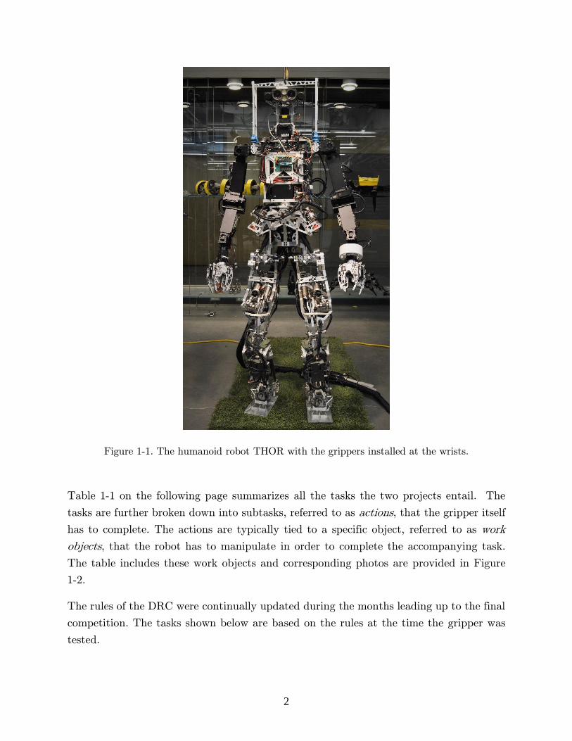
Figure 1-1. The humanoid robot THOR with the grippers installed at the wrists. .......... 2
Figure 1-2. Visual references of the work objects that need to be manipulated in order to complete the tasks. (a) ULTIMATIC B-BGH Tactical Fire Nozzle, (b) Stat-X First Responder 500 Fire Suppressant Canister, (c) Polaris XP 900 steering wheel, (d) Polaris XP 900 roll cage, (e) 1.5 x 3.5 x 36" and a 3.5 x 3.5 x 24" piece of lumber, (f) 12 x 12 x 48" aluminum truss, (g) Dewalt DCD980M2 cordless drill with a Morris 13042 saw drill bit, (h) large 18" diameter hand wheel valve, (i) small 9" diameter hand wheel, (j) 13" ball lever valve, (k) Shlage Standard Duty Door Lever handle ....................................... 4
Figure 3-1. A diagram of the original Mark 1 gripper design, showing (a) the right gripper and (b) the mirrored left gripper ........................................................................12
Figure 3-2. The actuator selected for use in the gripper, the Robotis MX-106R. ...........13
Figure 3-3. An illustration of the benefits of collinear fingers. (a) When torque τa is applied to two opposing fingers they apply F force on the object. (b) When the same torque is applied to two collinear fingers on the same side, they produce 2F force. .......16
Figure 3-4. The resulting cross sectional grasps produced when grasping, (a) the canister, (b) the 4x4 lumber, (c) a 30 mm diameter cylinder, and (d) a small 15 mm cube. ...............................................................................................................................17
Figure 3-5. The simplified low-level design of the gripper resulting from the 2D design process. ...........................................................................................................................18
Figure 3-6. An illustration of the benefits of rounded contact surfaces on the fingers. ...19
Figure 3-7. The evolution of the four-bar mechanism as it grasps an object. (a) Torque,
τa, is applied to the bottom member, (b) the finger rotates rigidly until the proximal phalanx contacts the object, (c) the distal phalanx breaks away from the mechanical hard stop and rotates while compressing the spring until it too contacts the object. .....20
Figure 3-8. The detail illustration of the four-bar underactuated mechanism used in the fingers. ............................................................................................................................21
Figure 3-9. The breakdown of all forces acting on each of the four members that make
up the underactuated mechanism. Each member’s orientation is specified by a single angle. ..............................................................................................................................23
Figure 3-10. The proximal contact force, Fk, plotted against the distal phalanx angle
while actuator torque, τa is held constant under two scenarios: (a) when kc is held constant as jc is varied; (b) and when jc is held constant as kc is varied. ........................27

viii
Figure 3-11. The force profiles for the (a) distal and (b) proximal contact forces based on the final set of geometric parameters presented in Table 3-2. Actuator torque was
held constant at τa = 4.2 Nm, half the MX-106R’s rated stall torque, and the proximal contact location was held constant at kc = 45 mm. ........................................................28
Figure 3-12. The stable and unstable states for our mechanism. ....................................29
Figure 3-13. Typical force profiles experienced when gripping; kc = kr = 35 mm, jc = jr = 45 mm and τa = 3.1 Nm. ............................................................................................30
Figure 3-14. (a) The design used to create recessed contact surfaces on the four palm plates and (b) the resulting design after assembly. .........................................................31
Figure 3-15. A close-up view of the gripper’s gear box. The gearbox cover is made transparent to improve clarity. .......................................................................................32
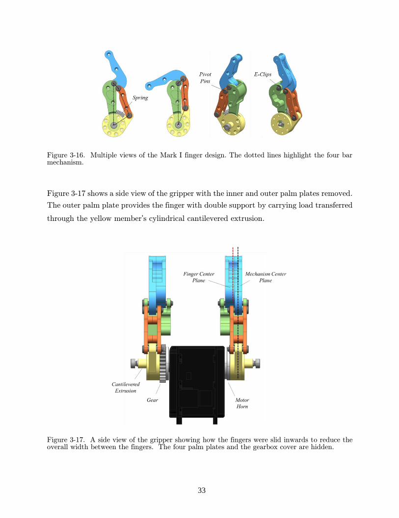
Figure 3-16. Multiple views of the Mark I finger design. The dotted lines highlight the four bar mechanism. .......................................................................................................33
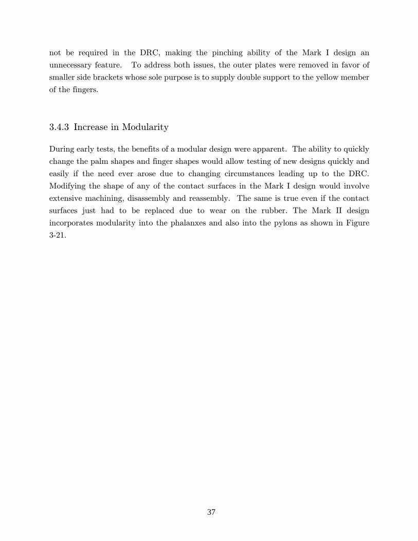
Figure 3-17. A side view of the gripper showing how the fingers were slid inwards to reduce the overall width between the fingers. The four palm plates and the gearbox cover are hidden. ............................................................................................................33
Figure 3-18. The design used to create recessed contact surfaces on the (a) proximal phalanx and (c) distal phalanx. Also shown is the assembled (b) proximal and (d) distal phalanxes. .............................................................................................................34
Figure 3-19. The assembled Mark I design. ....................................................................35
Figure 3-20. A comparison of the (a) Mark I and (b) Mark II gripper designs. ..............36
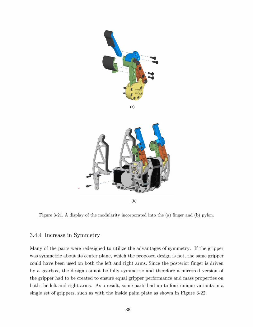
Figure 3-21. A display of the modularity incorporated into the (a) finger and (b) pylon. .......................................................................................................................................38
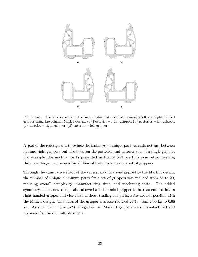
Figure 3-22. The four variants of the inside palm plate needed to make a left and right
handed gripper using the original Mark I design. (a) Posterior – right gripper, (b)
posterior – left gripper, (c) anterior – right gripper, (d) anterior – left gripper. ............39
Figure 3-23. The six Mark II grippers. ..........................................................................40
Figure 3-24. An overview of the process used to create the SAFFiR glove. (a) first a male mold was designed in CAD, (b) the mold was 3D printed in three smaller parts then combined, (c) Kevlar film was applied in certain areas using a custom pattern, and (d) several thin layers of urethane were brushed over the mold and Kevlar...................41
Figure 3-25. A comparison of the original and the slim distal phalanx. (a) The finger position when glove interferences are likely to happen, (b) a side view showing the respective clearances produced when using the (c) original and (d) slim distal phalanx.42
Figure 3-26. A visual of the final SAFFiR glove showing (a) the white cuff, (b) the sealing method used to prevent water seepage, and (c) the glove being used in an actual live-fire test. ...................................................................................................................43
Figure 4-1. The test setup used for the actuator torque tests and the steady state (SS) temperature test. ............................................................................................................46
Figure 4-2. The setup used to measure the actuators actual torque output. .................47
Figure 4-3. The measured relationship between the commanded torque level and the actual torque produced by the actuators. .......................................................................48

ix
Figure 4-4. The steady state temperature test being conducted in an environmental
chamber set to Tamb = 23 °C. ...........................................................................................50
Figure 4-5. Example data from the steady state temperature test for the operating
condition, Tamb = 23 °C with the glove off..........................................................................51
Figure 4-6. The measured steady state temperatures of the actuator at various torque levels for the four different operating conditions. The top most points are used as the nominal torque level for the actuator for that operating condition. ................................52
Figure 4-7. (a) The door used to measure the missing door handle criteria, (b) the method used for measuring the torque required to rotate the handle, and (c) the method used to measure the pull force required to open the door. ..............................................55
Figure 4-8. The measuring device used in the turning test. ............................................56
Figure 4-9. The five grasp orientations used during the turning test: (a) small hand wheel with a radial grasp, (b) large hand wheel with a radial grasp, (c) small hand wheel with an axial grasp, (d) large hand wheel with an axial grasp, and (e) door handle with an offset axial grasp. ..............................................................................................57
Figure 4-10. Example data measured by the F/T sensor while validating the door handle action with an offset axial grasp. ........................................................................58
Figure 4-11. The test equipment used in the trigger test. (a) The view from the front and (b) the view from the back. .....................................................................................60
Figure 4-12. (a) A depiction of the position variables varied during the trigger test and
(b) the initial position of the drill, θdrill = 0° and hgripper = 0 mm. .....................................61
Figure 4-13. A comparison of the resulting trigger pulls from using (a) the original distal phalanx and the (b) the slim distal phalanx. The original phalanx contacts the drill housing while the slim phalanx successfully compresses the trigger. .......................62
Figure 4-14. (a) The drill horizontal as it was during the trigger tests and (b) the drill tilted back which leads to more effective trigger actuation. ...........................................64
Figure 4-15. The grasps validated in the dynamic hold tests: (a) 4x4 lumber, (b) 2x4
lumber – horizontal, (c) 2x4 – vertical, (d) fire hose nozzle, (e) canister – horizontal, (f)
canister – vertical, and the (g) drill. ...............................................................................66
Figure 4-16. The preliminary static hold test. (a) The gripper is lowered to the desired location and (b) the gripper is closed and brought slowly upwards. (c) The multiple locations at which the grasp was tested. .........................................................................67
Figure 4-17. (a) The test equipment used in the dynamic hold test, (b) the robot’s actual arm, (c) the swing arm in the long configuration, and (d) the swing arm in the short configuration. ........................................................................................................68
Figure 4-18. An example of one of the trials conducted during the dynamic hold test. This specific trial was for the 4x4 lumber with the long swing arm in arm orientation B. .......................................................................................................................................69
Figure 4-19. The four arm orientations relative to the swing direction. (a) Arm Orientation A, (b) Arm Orientation B, (c) Arm Orientation C, and (d) Arm Orientation D ....................................................................................................................................69
Figure 4-20. A visual of the moment generated by the offset weight of the lumber. ......70
Figure 4-21. The grasps used to hold the lumber: (a) 2x4 – vertical, (b) 2x4 lumber – horizontal, and (c) 4x4 lumber. ......................................................................................71

x
Figure 4-22. (a) The Instron test setup and (b) the hollow aluminum cylinders that were tested. .............................................................................................................................74
Figure 4-23. The two cylinder constraining methods used in testing; (a) the fixed cylinder method and (b) the hinged cylinder method. ....................................................75
Figure 4-24. The articulated arm used to allow the gripper to move freely during the Instron test. ....................................................................................................................76
Figure 4-25. The grasp development midway through (a) a fixed cylinder trial and (b) a hinged cylinder trial. ......................................................................................................77
Figure 4-26. The results of the Instron test with the (a) fixed cylinder and (b) hinged cylinder. ..........................................................................................................................78
Figure 4-27. The resulting grasp produced by (a) cylinder 1, (b) cylinder 2, (c) cylinder 3, (d) cylinder 4. .............................................................................................................80
Figure A-1. The F/T sensor data for the door handle trial. ………………………………89
Figure A-2. The F/T sensor data for the axial large hand wheel trial. ...........................90
Figure A-3. The F/T sensor data for the radial large hand wheel trial. .........................90
Figure A-4. The F/T sensor data for the axial small hand wheel trial ...........................91
Figure A-5. The F/T sensor data for the radial small hand wheel trial .........................91
Figure A-6. The F/T sensor data for lever valve trial. ..................................................92

xi
List of Tables
Table 1-1. A summary of the tasks the robot has to complete according to the rules that were available 15 weeks before the DRC finals. ....................................................... 3
Table 3-1. The chosen dimensions of the fingers resulting from the 2D geometric design process. ...........................................................................................................................18
Table 3-2. The final geometric parameters chosen for our gripper design. ....................22
Table 4-1. The four tests developed to validate whether the gripper is capable of completing the corresponding actions. ............................................................................45
Table 4-2. A summary of the important torque level values of the actuators. The actual produced torque is estimated using Equation 23 and is shown in parenthesis. ...............53
Table 4-3. A summary of the required forces and torques needed to accomplish the corresponding actions. Note the only action requiring additional pull force is the door handle because it must be pulled open after turning it. .................................................54
Table 4-4. A summary of the results from the turning tests for the four actions being validated. ........................................................................................................................59
Table 4-5. The torque required to initiate and to complete trigger actuation while using the original and the slim distal phalanx for various positions. The actual torque is estimated using Equation 23 and is shown in parenthesis with units [Nm]. ...................63
Table 4-6. The results from the preliminary static hold test. .........................................70
Table 4-7. The results from the dynamic hold test. ........................................................72
Table 4-8. The diameters of the cylinders tested. ...........................................................74
Table 4-9. A summary of the results from the Instron test. ..........................................79

xii
List of Nomenclature
Ra Reaction force vector at point a [N]
Rax Reaction force at point a in the x-direction [N]
Ray Reaction force at point a in the y-direction [N]
ΣFa Summation of forces on member a [N]
ΣMa,b Summation of moments on member a about point b [Nm] *Bold variables denote vectors

1
1 Introduction
The gripper was built for the Tactical Hazardous Operations Robot (THOR), a 34 degree
of freedom (DOF) humanoid robot with superhuman range of motion and is shown in
Figure 1-1 [1]–[5]. THOR is designed specifically for the DARPA Robotics Challenge
(DRC) and the Shipboard Autonomous Fire Fighting Robot (SAFFiR) project which both
focus on placing robots instead of humans into dangerous environments to perform
important tasks .
The DRC is a competition sponsored by the Defense Advanced Research Projects Agency
(DARPA) to spur innovation in the robotics sector by funding multiple teams from around
the world to develop technologies that will advance the field in areas pertaining to disaster
response. The competition is based on a series of disaster response themed tasks that the
robots have to complete for points.
The SAFFiR project was a project funded by the Office of Naval Research to develop a
robot that one day could help sailors fight fires onboard naval vessels. Fires onboard
ships are incredibly dangerous for humans to fight especially inside the small tight quarters
often found on naval vessels. The heat, smoke, and toxic gases produced by fires tend
to get trapped inside the small areas of ships making breathing and seeing extremely
difficult for humans. Any technologies that can help alleviate these dangerous scenarios
for the crew are heavily sought after by the US Navy. A humanoid form factor was chosen
for this project because Navy ships are typically optimized for the human form in order
to get the most use out of the ship’s limited space.
2
Figure 1-1. The humanoid robot THOR with the grippers installed at the wrists.
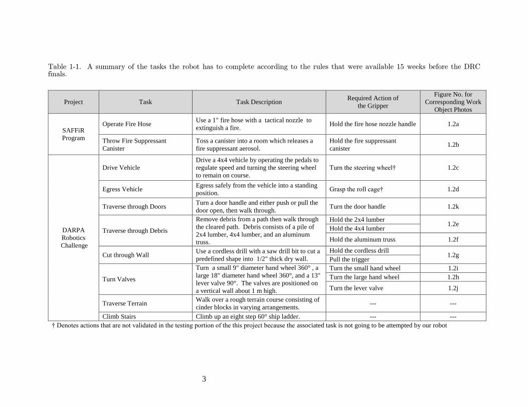
Table 1-1 on the following page summarizes all the tasks the two projects entail. The
tasks are further broken down into subtasks, referred to as actions, that the gripper itself
has to complete. The actions are typically tied to a specific object, referred to as work
objects, that the robot has to manipulate in order to complete the accompanying task.
The table includes these work objects and corresponding photos are provided in Figure
1-2.
The rules of the DRC were continually updated during the months leading up to the final
competition. The tasks shown below are based on the rules at the time the gripper was
tested.
3
Table 1-1. A summary of the tasks the robot has to complete according to the rules that were available 15 weeks before the DRC finals.
Project Task Task Description Required Action of
the Gripper
Figure No. for
Corresponding Work
Object Photos
SAFFiR
Program
Operate Fire Hose Use a 1" fire hose with a tactical nozzle to
extinguish a fire. Hold the fire hose nozzle handle 1.2a
Throw Fire Suppressant
Canister
Toss a canister into a room which releases a
fire suppressant aerosol.
Hold the fire suppressant
canister 1.2b
DARPA
Robotics
Challenge
Drive Vehicle
Drive a 4x4 vehicle by operating the pedals to
regulate speed and turning the steering wheel
to remain on course.
Turn the steering wheel† 1.2c
Egress Vehicle Egress safely from the vehicle into a standing
position. Grasp the roll cage† 1.2d
Traverse through Doors Turn a door handle and either push or pull the
door open, then walk through. Turn the door handle 1.2k
Traverse through Debris
Remove debris from a path then walk through
the cleared path. Debris consists of a pile of
2x4 lumber, 4x4 lumber, and an aluminum
truss.
Hold the 2x4 lumber 1.2e
Hold the 4x4 lumber
Hold the aluminum truss 1.2f
Cut through Wall Use a cordless drill with a saw drill bit to cut a
predefined shape into 1/2" thick dry wall.
Hold the cordless drill 1.2g
Pull the trigger
Turn Valves
Turn a small 9" diameter hand wheel 360° , a
large 18" diameter hand wheel 360°, and a 13"
lever valve 90°. The valves are positioned on
a vertical wall about 1 m high.
Turn the small hand wheel 1.2i
Turn the large hand wheel 1.2h
Turn the lever valve 1.2j
Traverse Terrain Walk over a rough terrain course consisting of
cinder blocks in varying arrangements. --- ---
Climb Stairs Climb up an eight step 60° ship ladder. --- ---
† Denotes actions that are not validated in the testing portion of the this project because the associated task is not going to be attempted by our robot

4
Figure 1-2. Visual references of the work objects that need to be manipulated in order to complete the tasks. (a) ULTIMATIC B-BGH Tactical Fire Nozzle, (b) Stat-X First Responder 500 Fire Suppressant Canister, (c) Polaris XP 900 steering wheel, (d) Polaris XP 900 roll cage, (e) 1.5 x 3.5 x 36" and a 3.5 x 3.5 x 24" piece of lumber, (f) 12 x 12 x 48" aluminum truss, (g) Dewalt DCD980M2 cordless drill with a Morris 13042 saw drill bit, (h) large 18" diameter hand wheel valve, (i) small 9" diameter hand wheel, (j) 13" ball lever valve, (k) Shlage Standard Duty Door Lever handle
Due to limited time and resources the robot will not be attempting to drive or egress the
4x4 vehicle and so the gripper will not have to complete the associated actions. Therefore,
the two corresponding actions are not explicitly validated in the testing phase of the
gripper, although they are referred to and discussed occasionally throughout the chapters.
5
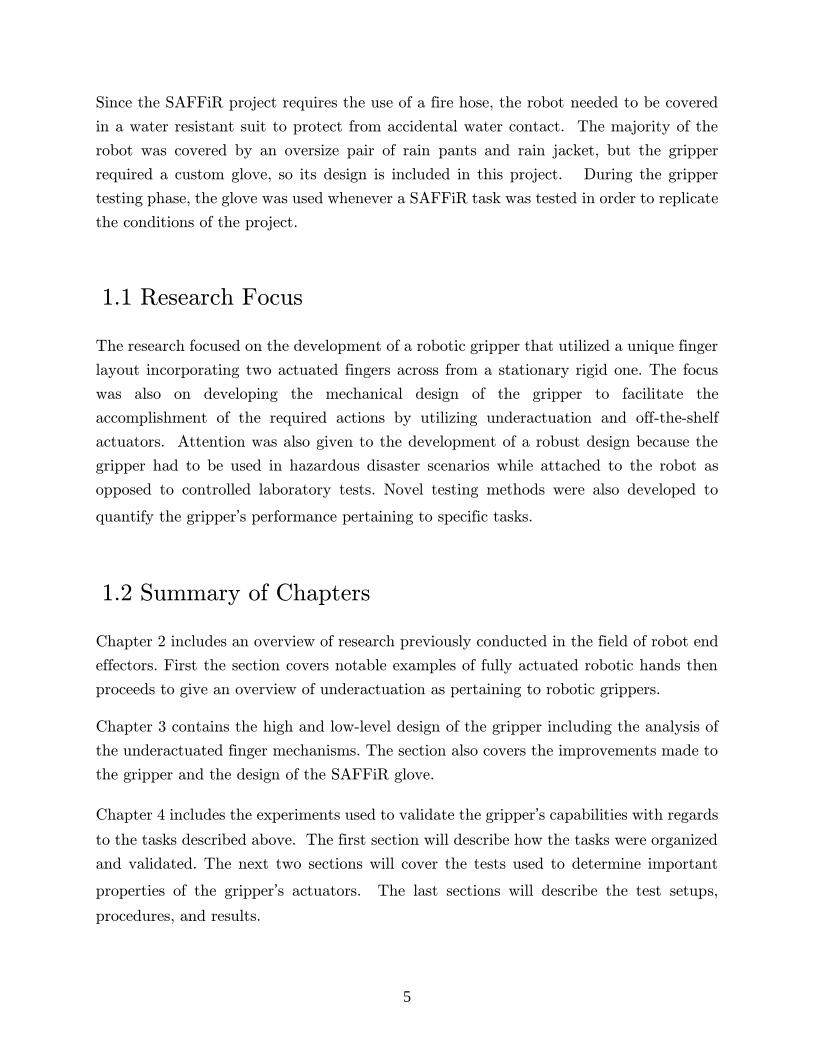
Since the SAFFiR project requires the use of a fire hose, the robot needed to be covered
in a water resistant suit to protect from accidental water contact. The majority of the
robot was covered by an oversize pair of rain pants and rain jacket, but the gripper
required a custom glove, so its design is included in this project. During the gripper
testing phase, the glove was used whenever a SAFFiR task was tested in order to replicate
the conditions of the project.
1.1 Research Focus
The research focused on the development of a robotic gripper that utilized a unique finger
layout incorporating two actuated fingers across from a stationary rigid one. The focus
was also on developing the mechanical design of the gripper to facilitate the
accomplishment of the required actions by utilizing underactuation and off-the-shelf
actuators. Attention was also given to the development of a robust design because the
gripper had to be used in hazardous disaster scenarios while attached to the robot as
opposed to controlled laboratory tests. Novel testing methods were also developed to
quantify the gripper’s performance pertaining to specific tasks.
1.2 Summary of Chapters
Chapter 2 includes an overview of research previously conducted in the field of robot end
effectors. First the section covers notable examples of fully actuated robotic hands then
proceeds to give an overview of underactuation as pertaining to robotic grippers.
Chapter 3 contains the high and low-level design of the gripper including the analysis of
the underactuated finger mechanisms. The section also covers the improvements made to
the gripper and the design of the SAFFiR glove.
Chapter 4 includes the experiments used to validate the gripper’s capabilities with regards
to the tasks described above. The first section will describe how the tasks were organized
and validated. The next two sections will cover the tests used to determine important
properties of the gripper’s actuators. The last sections will describe the test setups,
procedures, and results.

6
Chapter 5 will summarize the work and provide a high level overview of the gripper’s
performance with regards to the required tasks. The section then ends with
recommendations.
7
2 Literature Review
Robot end effectors are generally classified as any device attached to a robotic system
that is used to physically interact with the robot’s environment. Some propose a further
classification into two general groupings: robotic hands and robotic grippers. Hands are
said to be designed with the intent of being anthropomorphic and fully actuated and as
a result are typically more complex. Grippers, on the other hand, tend to be simpler,
more utilitarian and tend to take the shape of whatever the design requires [6]. Another
method of differentiating is to compare the number of actuators, nact, an end effector
contains to its number of DOF, nDOF. If nDOF = nact the end effector is said to be fully
actuated, if nDOF > nact, it is said to be underactuated.
2.1 Fully Actuated Robot End Effectors
The first robot end effector used in a modern robotic system is generally accredited to a
simple pincher gripper built in 1952 by the Argonne Laboratory for radioactive material
handling [7]. Soon after in 1960, General Electric is known for developing the Handyman
robot which incorporates one of the first end effectors with more than one phalanx per
finger [8].
During the next couple decades, a large portion of research was dedicated to fully actuated
end effectors in hopes of developing one that was capable of imitating the capabilities of
the human hand. Some notable examples are the Okanda Hand developed in Japan, the
Salisbury Hand developed jointly by Stanford University and the Jet Propulsion
Laboratory (JPL), the UTAH/MIT Hand developed jointly by the University of Utah
and the Massachusetts Institute of Technology (MIT), the DLR Hands I & II developed
8
by the German Aerospace Center, the Shadow Dexterous Hand, and the Sandia Hand
developed by Sandia National Laboratories[9]–[14].
All the hands listed above, expect the DLR Hands, were cable driven by tendons; a feature
that is often necessary when creating robotic hands with many degrees of actuation
because the use of tendons gives the designer the flexibility to place actuators away from
their respective joints. Implementing tendons, though, can be difficult due to complex
routing and tensioning.
2.2 Underactuated Robot End Effectors
In the 1990s, there was a rise in relevance of underactuated end effectors. This is thought
to be due to the difficulties associated with the increasing complexity of fully actuated
robotic hands [15]. Underactuation supplies added compliance and dexterity without the
need of adding additional actuators and sensors. Through the careful design of the end
effector’s mechanical makeup, underactuation can be used to great advantage [16].
Underactuation in hand-like mechanisms can be traced back to patents from the 1800s
[17]. The first modern use, though, is typically associated with the Soft Gripper developed
in 1978 which was a large ten-phalanx two finger cable driven gripper [18]. The Soft
Gripper worked so well that many end effectors used almost the exact same
underactuation method in their preceding designs such as with the TAKO Flyer, the RTR
II Hand, and the 100G Hand [6], [19].
A more recent underactuated tendon-driven end effector is the SDM Hand which was
jointly developed by Yale and Harvard. The design utilized polymer-based shape
deposition manufacturing to create elastic joints and was intended to produce a large
variety of practical robust grasps [20]. The design was then used as a starting point for
the creation of the iHY Hand, a gripper developed jointly by iRobot, Harvard, and Yale
for the DARPA ARM-H competition, a competition created to spur innovation in robot
end effector hardware [21]. The iHY Hand and the Sandia Hand mentioned previously
both placed highly in this competition. As a result, both were supplied to Track B teams
in the DRC to use on the their ATLAS humanoid robots which were supplied by Boston
Dynamics [22].
9
Stanford University helped develop the underactuated tendon based grippers used by
RoboSimian, JPL’s quadruped entry into the DRC. This gripper had to overcome the
unique challenge of being not just used for manipulation but also being walked on as feet
[23].
As opposed to tendons, another method of producing underactuation is through
mechanical linkages. Linkages are typically simpler, more robust, and are able to transfer
larger forces. As a result, a linkage based mechanism is used later in the design preposed
in this work.
One of the first impressive linkage-based grippers was the Odetics Hand, which could
either produce a powerful encompassing grasp or keep its distal phalanxes parallel and
operate as a parallel pincher [24]. The Adroit Hand and Delft Hand developed by HDT
Global and Delft University of Technology, respectively, are two more examples of very
functional grippers using linkages [25]–[27]. The Delft Hand, designed for food handling,
uses a four bar mechanism and is the closest gripper to resemble the final design in this
work.
The Laval University Robotics Laboratory was one of the largest contributors to the
development of linkage based underactuated grippers. They produced a majority of the
literature on the analysis of underactuated grasps not just for linkage mechanisms but for
all mechanism types. They were also the first to supply conclusive analysis on the stability
of underactuated grasps [28]–[33]. Their lab was responsible for developing the MARS
gripper which had similar performance to the Odetics Hand [34]. They then removed an
actuator from MARS in a redesign to further underactuate the gripper and subsequently
created the SARAH Hand, which was to be used on the Canadian Space Arm [35].
Multiple versions of the SARAH Hand were created including a more compact version
called SARAH CSA, a pneumatic version called Air SARAH, a tendon-based version for
prosthetic research, and a version for radioactive material handling called SARAH
UKAEA [6], [36]. A company called Robotiq spun off from the Laval University Robotics
Laboratory which went on to develop arguably some of the most practical and widely
used underactuated grippers commercially available. Robotiq offers a two-finger and
three-finger gripper, with the latter having similar functionality to the SARAH Hand and
is the gripper of choice for many teams in the DRC [37], [38].
10
2.3 Semi-underactuated End Effectors
Some end effectors use creative methods of compliance that are similar to underactuation
but are not generally accepted into the same family [39]. One of these end effectors is the
very functional BarrettHand which uses a novel TorqueSwitch mechanism which
automatically transfers one motor’s power to different phalanges only when needed [40].
Another is the SRI Hand which utilizes electro-static brakes at each joint to create a novel
clutching mechanisms that selectively locks degrees of freedom during a grasp [41]. Lastly
the FinGripper developed by Festo and EvoLogics uses a carefully designed, mostly
hollow, flexible, triangular finger that adapts to the shape of objects while requiring only
one actuator to grasp [42].
11
3 Design
Two gripper versions were designed and manufactured. An initial Mark I design was
improved upon to create an upgraded Mark II design which was subsequently used in the
testing phase of the project. The following sections present an overview of the design
philosophy, a description of the finger mechanism, an explanation of the improvements to
the Mark II design, and lastly a description of the SAFFiR glove design.
As previously stated the design of the gripper was driven exclusively by the tasks involved
in the DRC and SAFFiR project. The gripper design that was sought was one capable
of completing all the manipulation tasks associated with the two projects while also
balancing other secondary design criteria such as low weight, robustness, and low
additional system complexity.
Low weight allows the arm to carry heavier objects and reduces the overall load applied
to the already overburdened leg joints of the robot. The gripper will undoubtedly collide
with other objects during normal use, so it must be robust enough to not only withstand
the loads applied during manipulation but also withstand the loads produced from
accidental collisions. The robot is built around a complex internal electro-mechanical
system and any increase to its complexity associated with the implementation of the
gripper was strongly avoided.
3.1 High-level Gripper Design
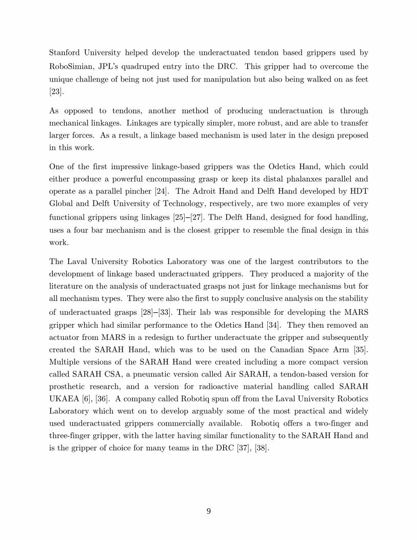
Figure 3-1 presents the Mark I design. The gripper consisted of two underactuated fingers
across from two rigid hollow pylons. Each finger has two DOF corresponding to each of
their two phalanges, but each finger is powered by only a single actuator. Both fingers
are positioned to rotate about the same proximal axis requiring the use of a geared
12
transmission to connect the lower actuator to the posterior finger. Due to the asymmetry
caused by the geared transmission, the gripper requires a separate mirrored variant to
create a set of symmetric grippers for our bimanual robot.
Figure 3-1. A diagram of the original Mark 1 gripper design, showing (a) the right gripper and (b) the mirrored left gripper
13
3.1.1 Actuator Selection
Actuator selection was conducted early in the design process because it had significant
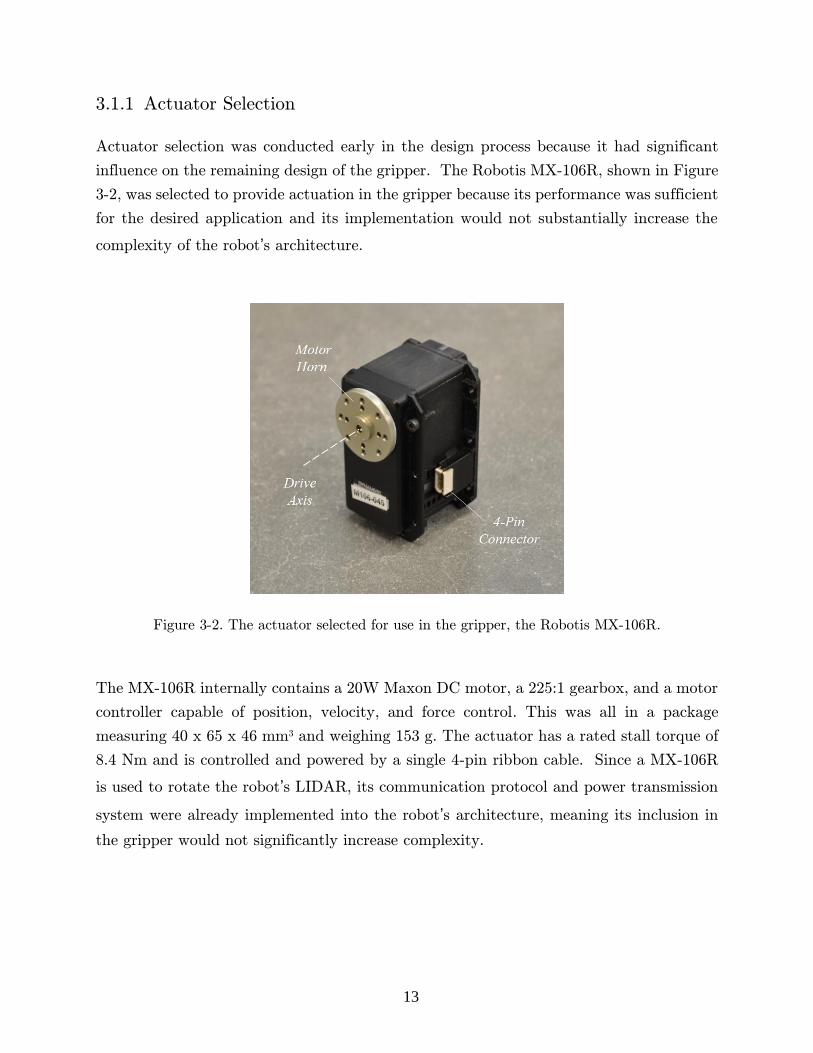
influence on the remaining design of the gripper. The Robotis MX-106R, shown in Figure
3-2, was selected to provide actuation in the gripper because its performance was sufficient
for the desired application and its implementation would not substantially increase the
complexity of the robot’s architecture.
Figure 3-2. The actuator selected for use in the gripper, the Robotis MX-106R.
The MX-106R internally contains a 20W Maxon DC motor, a 225:1 gearbox, and a motor
controller capable of position, velocity, and force control. This was all in a package
measuring 40 x 65 x 46 mm3 and weighing 153 g. The actuator has a rated stall torque of
8.4 Nm and is controlled and powered by a single 4-pin ribbon cable. Since a MX-106R
is used to rotate the robot’s LIDAR, its communication protocol and power transmission
system were already implemented into the robot’s architecture, meaning its inclusion in
the gripper would not significantly increase complexity.
14
3.1.2 Actuator Control
In order to control the fingers, it was decided to utilize position control on the MX-106R’s
while occasionally modifying the actuator’s torque level, which limits the amount of torque
the actuator is allowed to produce. The torque level is defined by a 10 bit registry value
in the MX-106R’s internal motor controller and ranges from 0 to 1023, which loosely
correlates to applying between 0 and 100% of the actuator’s theoretical maximum torque.
The actuators have multiple built-in safety features to protect their internal electronics
from damage. The two most relevant safety features for this project are the actuator’s
temperature limit and overload limit.
The temperature limit triggers a motor shutdown when the internal actuator temperature,
Tint, exceeds 80 °C. The overload limit triggers a motor shutdown when the motor
controller senses an overcurrent occurring somewhere internally. On the gripper, the
triggering of either limit would likely lead to the complete loss of grip integrity and likely
cause the work object to dislodge from the gripper. Therefore, the triggering of the limits
was actively avoided.
During early testing, it was found the overload limit would begin to sporadically trigger
when the torque level was set to be higher than 350. So in order to avoid seemingly
unpredictable motor shutdowns, the torque level would need to be limited to 350;
essentially limiting the actuator’s torque to ~35% of its maximum value.
Instead the overload safety feature was disabled in the actuator’s software. Doing so
allowed the motors to operate safely up to a torque level of 700, after which point the
internal hardware would begin to sustain irreversible thermal damage and the motor
would begin to seize. As a result, with a 1.4 factor of safety, 500 was selected to be used
as the MX-106R’s maximum recommended toque level for short time periods and that
value is referred herein to as the actuator’s maximum torque level. Note the temperature
limit will trigger if the actuator remains at the maximum torque level for extended periods
of time. As per the manufacturer’s strong recommendation, the temperature safety limit
feature was left intact and unaltered.
15
3.1.3 Number of Fingers, Phalanxes, and Actuators
It was determined early in the DRC project that the robot would benefit from having the
drill turned off while walking to reduce the vibration introduced in the system’s sensors.
In order to accomplish this goal, the gripper would have to hold the drill without actuating
the trigger. The fewest number of actuators needed to accomplish this was two, one to
hold the drill and one to independently actuate the trigger. As a result, the gripper was
designed to incorporate two actuators and two fingers.
It was decided to incorporate only two phalanxes per finger. During the 2D geometric
design process discussed later, it was determined that two phalanxes was the least number
needed to achieve a reasonably secure grasp on all the work objects.
3.1.4 Finger Positions
Many two-finger grippers are arranged so their fingers sit opposite each other creating a
pincher-like mechanism. The two fingers were positioned next to each other collinearly
so they share the same proximal rotation axis and sit across from two rigid pylons. In
this configuration, the two fingers tend to work with each other as opposed to against,
producing potentially double the gripping force compared with the conventional pincher
configuration as illustrated in Figure 3-3.
16
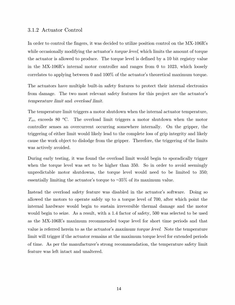
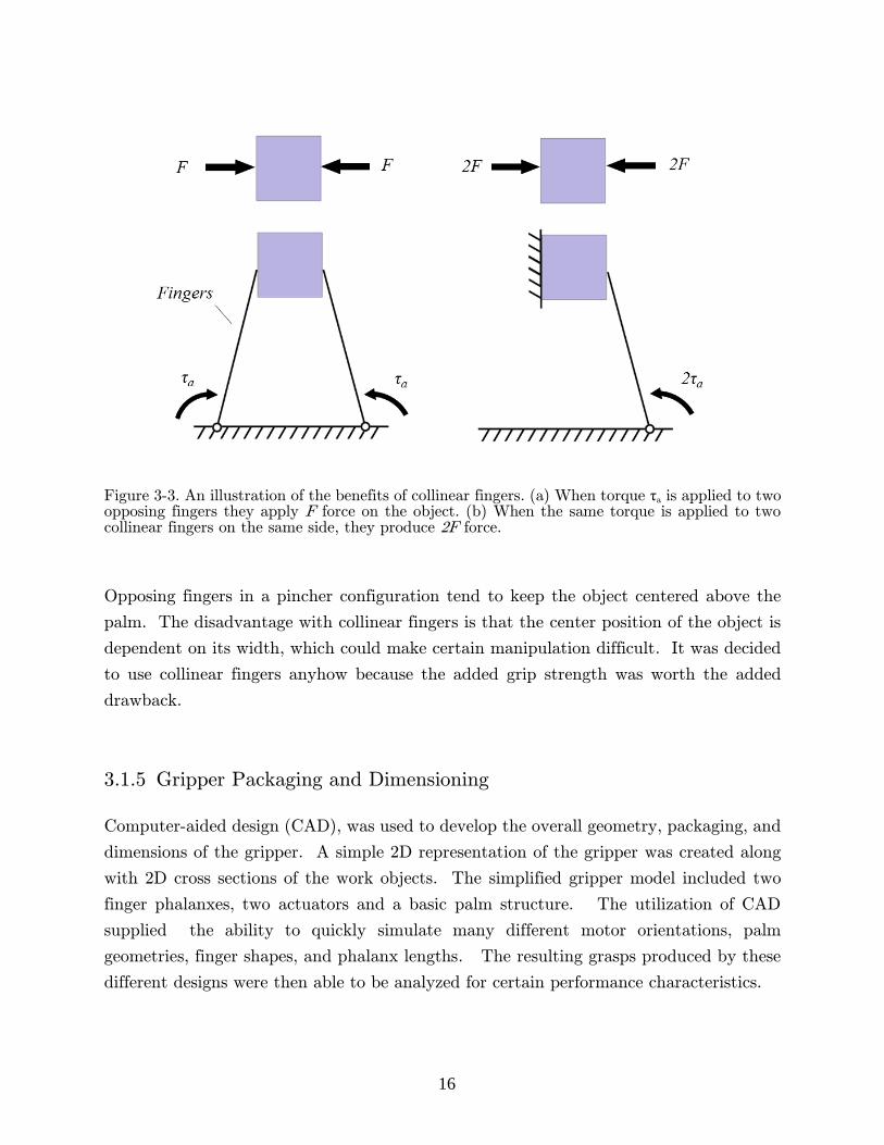
Figure 3-3. An illustration of the benefits of collinear fingers. (a) When torque τa is applied to two opposing fingers they apply F force on the object. (b) When the same torque is applied to two collinear fingers on the same side, they produce 2F force.
Opposing fingers in a pincher configuration tend to keep the object centered above the
palm. The disadvantage with collinear fingers is that the center position of the object is
dependent on its width, which could make certain manipulation difficult. It was decided
to use collinear fingers anyhow because the added grip strength was worth the added
drawback.
3.1.5 Gripper Packaging and Dimensioning
Computer-aided design (CAD), was used to develop the overall geometry, packaging, and
dimensions of the gripper. A simple 2D representation of the gripper was created along
with 2D cross sections of the work objects. The simplified gripper model included two
finger phalanxes, two actuators and a basic palm structure. The utilization of CAD
supplied the ability to quickly simulate many different motor orientations, palm
geometries, finger shapes, and phalanx lengths. The resulting grasps produced by these
different designs were then able to be analyzed for certain performance characteristics.

17
The grasp’s performance was estimated by observing the direction and location of the
resulting contact forces. Designs that produced force vectors which pushed objects down
into the palm and across into the vertical palm structure were deemed favorable while
designs that appeared to push the objects out of the palm were deemed unfavorable.
Using this method, a configuration was developed that resulted in a compact simple design
that appeared to produce favorable grasps on all the various sized work objects. This
configuration was used in the final gripper design and is shown in Figure 3-4 along with
the various grasps it produced in the 2D design process.
Figure 3-4. The resulting cross sectional grasps produced when grasping, (a) the canister, (b) the 4x4 lumber, (c) a 30 mm diameter cylinder, and (d) a small 15 mm cube.
As seen in Figure 3-4a and b the palm structure had to be extended vertically creating
pylons to supply an additional surface for the larger work objects to be secured against.
The pylons also supply a surface for the gripper to pinch small objects against; a feature
that was unknown if needed at the time of the design phase but incorporated as a
precaution. The pinching surface was offset at a slight angle to complement the angle the
finger would likely be in while pinching small objects as seen in Figure 3-4d. The simple
18
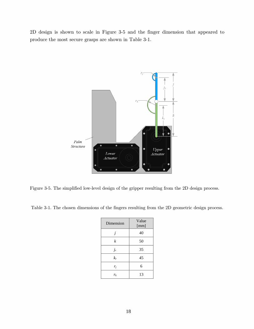
2D design is shown to scale in Figure 3-5 and the finger dimension that appeared to
produce the most secure grasps are shown in Table 3-1.
Figure 3-5. The simplified low-level design of the gripper resulting from the 2D design process.
Table 3-1. The chosen dimensions of the fingers resulting from the 2D geometric design process.
Dimension Value
[mm]
j 40
k 50
jr 35
kr 45
rj 6
rk 13
19
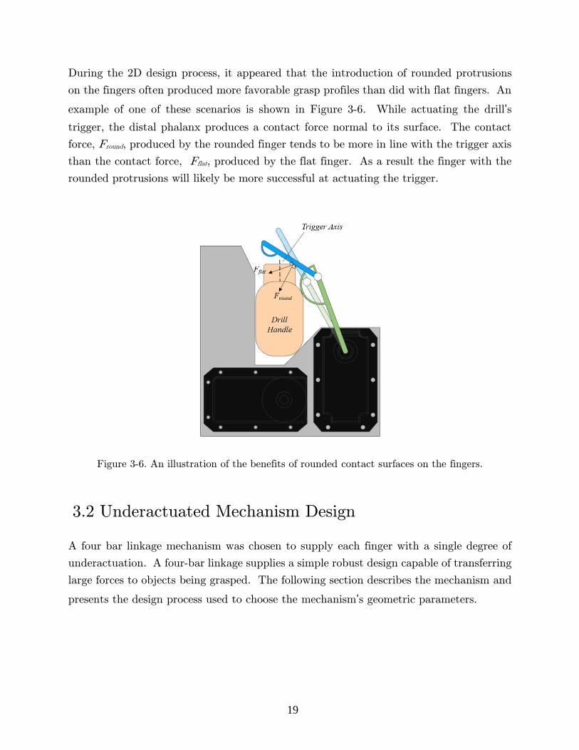
During the 2D design process, it appeared that the introduction of rounded protrusions
on the fingers often produced more favorable grasp profiles than did with flat fingers. An
example of one of these scenarios is shown in Figure 3-6. While actuating the drill’s
trigger, the distal phalanx produces a contact force normal to its surface. The contact
force, Fround, produced by the rounded finger tends to be more in line with the trigger axis
than the contact force, Fflat, produced by the flat finger. As a result the finger with the
rounded protrusions will likely be more successful at actuating the trigger.
Figure 3-6. An illustration of the benefits of rounded contact surfaces on the fingers.
3.2 Underactuated Mechanism Design
A four bar linkage mechanism was chosen to supply each finger with a single degree of
underactuation. A four-bar linkage supplies a simple robust design capable of transferring
large forces to objects being grasped. The following section describes the mechanism and
presents the design process used to choose the mechanism’s geometric parameters.

20
3.2.1 Mechanism Description
Figure 3-7 demonstrates how a typical four-bar linkage mechanism is utilized in an
underactuated finger design. A spring is used to keep the distal phalanx rigid when not
contacting an object by pulling the distal phalanx against a mechanical hard stop. Torque
is applied to the bottom linkage and the entire finger rotates about the bottom pivot point
as a rigid body. The proximal phalanx stops rotating when it contacts an object. At this
point the spring begins to compress and the distal phalanx breaks away from its neutral
position and begins to close until it too contacts the object.
Figure 3-7. The evolution of the four-bar mechanism as it grasps an object. (a) Torque, τa, is applied to the bottom member, (b) the finger rotates rigidly until the proximal phalanx contacts the object, (c) the distal phalanx breaks away from the mechanical hard stop and rotates while compressing the spring until it too contacts the object.
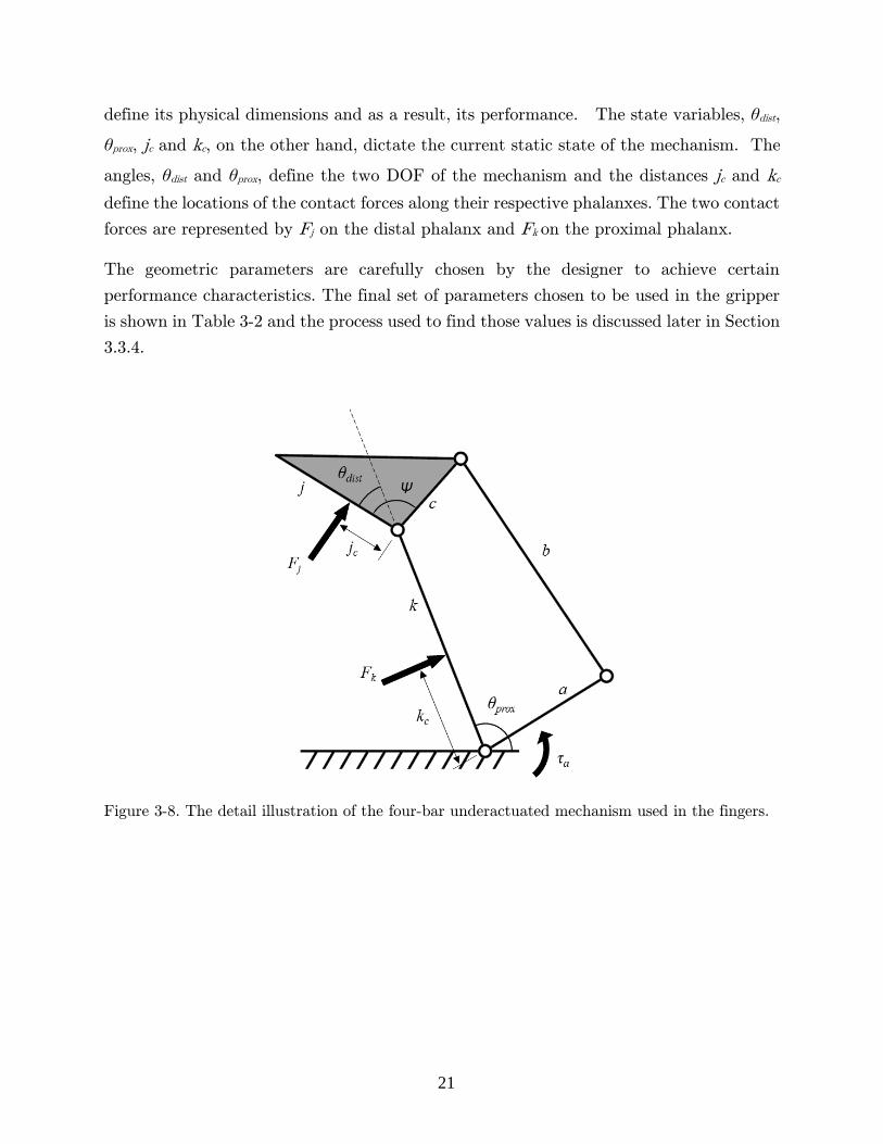
Figure 3-8 presents the mechanism in detail along with the parameters that
describe it based on the model presented by Birglen [33]. The variables shown in the
figure are split into two categories: geometric parameters and state variables. The lengths
k, j, a, b, c, and the angle Ψ represent the geometric parameters of the mechanism which
21
define its physical dimensions and as a result, its performance. The state variables, θdist,
θprox, jc and kc, on the other hand, dictate the current static state of the mechanism. The
angles, θdist and θprox, define the two DOF of the mechanism and the distances jc and kc
define the locations of the contact forces along their respective phalanxes. The two contact
forces are represented by Fj on the distal phalanx and Fk on the proximal phalanx.
The geometric parameters are carefully chosen by the designer to achieve certain
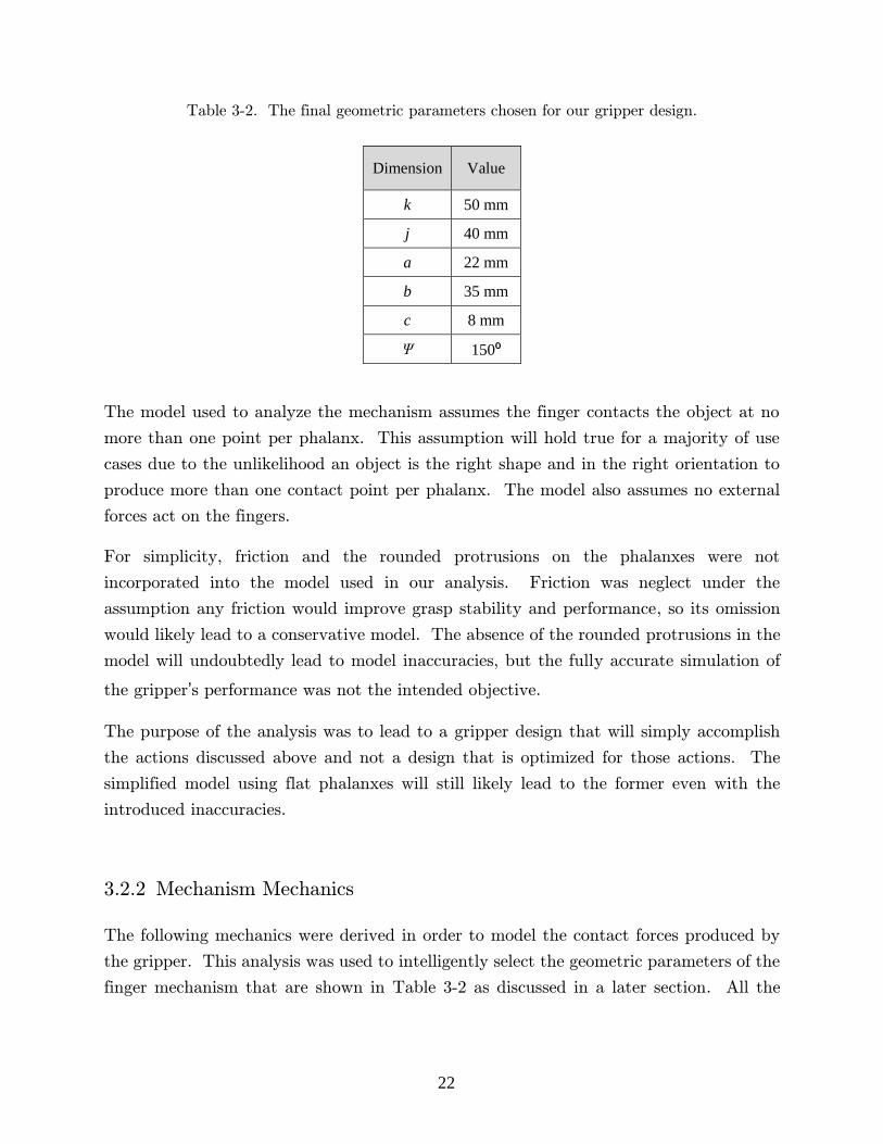
performance characteristics. The final set of parameters chosen to be used in the gripper
is shown in Table 3-2 and the process used to find those values is discussed later in Section
3.3.4.
Figure 3-8. The detail illustration of the four-bar underactuated mechanism used in the fingers.
22
Table 3-2. The final geometric parameters chosen for our gripper design.
Dimension Value
k 50 mm
j 40 mm
a 22 mm
b 35 mm
c 8 mm
Ψ 150⁰
The model used to analyze the mechanism assumes the finger contacts the object at no
more than one point per phalanx. This assumption will hold true for a majority of use
cases due to the unlikelihood an object is the right shape and in the right orientation to
produce more than one contact point per phalanx. The model also assumes no external
forces act on the fingers.
For simplicity, friction and the rounded protrusions on the phalanxes were not
incorporated into the model used in our analysis. Friction was neglect under the
assumption any friction would improve grasp stability and performance, so its omission
would likely lead to a conservative model. The absence of the rounded protrusions in the
model will undoubtedly lead to model inaccuracies, but the fully accurate simulation of
the gripper’s performance was not the intended objective.
The purpose of the analysis was to lead to a gripper design that will simply accomplish
the actions discussed above and not a design that is optimized for those actions. The
simplified model using flat phalanxes will still likely lead to the former even with the
introduced inaccuracies.
3.2.2 Mechanism Mechanics
The following mechanics were derived in order to model the contact forces produced by
the gripper. This analysis was used to intelligently select the geometric parameters of the
finger mechanism that are shown in Table 3-2 as discussed in a later section. All the

23
forces acting on the four members of the mechanism were specified as shown in Figure
3-9.
Figure 3-9. The breakdown of all forces acting on each of the four members that make up the
underactuated mechanism. Each member’s orientation is specified by a single angle.
The mechanism has two DOF which means two of the angles in Figure 3-9 must be
prescribed to completely describe the mechanism’s position. In our analysis, the proximal
phalanx was prescribed to remain stationary at θprox = 90° while prescribing the distal
phalanx angle, θdistal, to iterate from 0 to 100°. The two state variable angles were related
to the new angles introduced in Figure 3-9 through the two equations,
θdist = θc + Ψ-θk (1)
θprox = θk-π . (2)
After prescribing the two phalanx angles, the values of the remaining angles θa , θb , θc ,
and θk were calculated using Equations 1 and 2 and the following vector loop equation,
𝒂 + 𝒃 + 𝒄 + 𝒌 = 0 (3)

24
where a, b ,c, and k are the position vectors of the members,
𝒂 = [𝑎 cos 𝜃𝑎
𝑎 sin 𝜃𝑎] (4)
𝒃 = [𝑏 cos 𝜃𝑏
𝑏 sin 𝜃𝑏] (5)
𝒄 = [𝑐 cos 𝜃𝑐
𝑐 sin 𝜃𝑐] (6)
𝒌 = [𝑘 cos 𝜃𝑘
𝑘 sin 𝜃𝑘] . (7)
Assuming quasistatic equilibrium, the following static equations were specified to solve
for the contact forces,
∑ 𝑭𝒂 = 𝑹𝟐 − 𝑹𝟏 = 𝟎 (8)
∑ 𝑭𝒃 = 𝑹𝟑 − 𝑹𝟐 = 𝟎 (9)
∑ 𝑭𝒄 = 𝑹𝟒 − 𝑹𝟑 + 𝑭𝒋 = 𝟎 (10)
∑ 𝑭𝒌 = 𝑹𝟓 − 𝑹𝟒 + 𝑭𝒌 = 𝟎 (11)
where each equation represents the summation of forces on a member. The moments at each pivot point were represented by the equations,
∑ 𝑀𝑎,1 = 𝒂 × 𝑹𝟐 + 𝝉𝒂 = 0 (12)
∑ 𝑀𝑏,2 = 𝒃 × 𝑹𝟑 = 0 (13)
∑ 𝑀𝑐,3 = 𝒄 × 𝑹𝟒 + (𝒄 + 𝒋𝒄) × 𝑭𝒋 = 0 (14)

25
∑ 𝑀𝑘,4 = 𝒌 × 𝑹𝟓 + (𝒌 − 𝒌𝒄) × 𝑭𝒌 = 0 . (15)
The forces are defined as,
𝑹𝟏 = [𝑅1𝑥
𝑅1𝑦] (16)
𝑹𝟐 = [𝑅2𝑥
𝑅2𝑦] (17)
𝑹𝟑 = [𝑅3𝑥
𝑅3𝑦] (18)
𝑹𝟒 = [𝑅4𝑥
𝑅4𝑦] (19)
𝑹𝟓 = [𝑅5𝑥
𝑅5𝑦] (20)
𝑭𝒋 = [𝐹𝑗 cos (𝜃𝑐 + 𝛹 −
3𝜋
2)
𝐹𝑗 sin (𝜃𝑐 + 𝛹 −3𝜋
2)
] (21)
𝑭𝒌 = [𝐹𝑘 cos (𝜃𝑘 +
𝜋
2)
𝐹𝑘 sin (𝜃𝑘 +𝜋
2)
] . (22)
Equations 8-15 can be solved simultaneously to calculate the reaction forces including the
two important forces, Fj and Fk. This approach was used in the remaining sections to
calculate the force profiles produced by various mechanisms defined by various sets of
geometric parameters.
26
3.2.3 Grasp Stability
The following section describes how stability is determined for a given state of the
mechanism. The above equations solve for the contact forces needed on both phalanxes
to keep the mechanism in static equilibrium for a given actuator torque and given finger
position. An important observation is that the mechanism is capable of only producing
positive force at its contact points [6]. If friction is neglected and a negative contact force
is required to keep the mechanism in static equilibrium the phalanx requiring the negative
force will pull away from the object as the other phalanx begins to slide along the object.
This scenario leads to a less secure and unfavorable grasp. In practice, though, the friction
between the finger and the object may in fact stop the phalanx from pulling away, but
the resulting grasp will still loose grip security. As a result, a modeled grasp is taken to
be stable only if both contact force are positive [32].
When the distal angle, θdist, is constrained between 0 and 100°, as it is in the above model,
the distal phalanx will never require a negative contact force to keep the mechanism in
static equilibrium [33]. In some cases though, the proximal phalanx will require a negative
force to do so. As a result, the sign of the proximal contact force is the sole indicator of
grasp stability. If the resulting proximal contact force, Fk, is positive, the grasp is stable;
if it is negative, the grasp is unstable. Through careful design of the geometric parameters,
the cases in which Fk becomes negative can be reduced and thus the cases of instability
can also be reduced.
In order to ensure stability in a grasp, one must know the variables that influence the
sign of Fk. Excluding the mechanism’s geometric parameters, Fk is dependent on the three
state variables: θdist , jc , and kc. The actuator torque, τa, acts as a scalar multiplier on Fk
and therefore has no influence on its sign.
Figure 3-10 shows Fk calculated using Equations 8 - 15 for the mechanism defined by the
set of geometric parameter in Table 3-2. As can be seen in the figure, varying the distal
contact location, jc , changes at which distal phalanx angle, Fk flips signs, while varying
the proximal contact location, kc , does not. As also can be seen, the distal phalanx angle,
θdist ,clearly influences the sign of Fk. Therefore, the sign of Fk and thus stability are only
dependent on the state variables, jc and θdist, for a given mechanism. As a result, these
two parameters are the ones that are varied when observing the stability of the
mechanism, as is done in the proceeding section.

27
Figure 3-10. The proximal contact force, Fk, plotted against the distal phalanx angle while actuator
torque, τa is held constant under two scenarios: (a) when kc is held constant as jc is varied; (b) and when jc is held constant as kc is varied.
3.2.4 Geometric Parameter Selection
The geometric parameter shown in Table 3-2 were selected in order to achieve certain
performance criteria. The selection process was driven mostly by two criteria: to produce
enough force at the distal phalanx to compress the trigger of the drill and to minimize the
states that lead to instability. These two criteria tended to be inversely related and so a
balance between the two had to be found while selecting the mechanism’s geometric
parameters.
During the design phase a DeWALT DC759 cordless drill was used for reference knowing
the drill used in the DRC would be similar. The drill’s trigger pull weight was measured
to be 19.6 N at full compression. Using the 2D model from Figure 3-5, it was estimated
that the distal phalanx angle and the distal contact location to be θdist ≈ 60° and jc ≈ 24
mm, respectively, when the trigger was completely compressed. Knowing this, the first
design criteria was quantified by creating a requirement that the geometric parameters of
the mechanism had be chosen to ensure the distal contact force, Fj, was larger than 19.6
N with a 3.5 factor of safety at θdist = 60° and jc = 24 mm. A rather large factor of safety
of 3.5 was chosen to compensate for the many unknowns associated with pulling the
trigger.
28
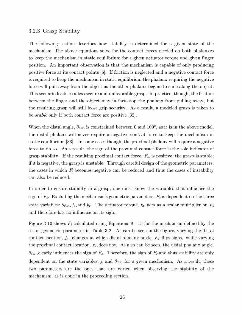
For the second design criteria, a Matlab script was created to estimate the areas of
stability for a given set of mechanism parameters. The script estimated both the distal
and proximal contact forces over a range of distal angles and distal contact locations, the
only two variables found to influence stability as discussed in the previous section. An
example of the force profiles produced by the script is shown in Figure 3-11. The grey
planes in the figure represent the planes associated with zero contact force. If the force
profiles are below the grey plane, the finger is producing an unstable grasp at that specific
state. Note the distal contact force is never below this plane as mentioned earlier.
Using the script, the force profiles produced by various sets of geometric parameters were
observed which were manually iterated until the two design criteria were adequately
fulfilled. The resulting set of parameters are those shown in Table 3-2. The resulting
force profiles produced by our finger mechanism are shown in Figure 3-11.
Figure 3-11. The force profiles for the (a) distal and (b) proximal contact forces based on the
final set of geometric parameters presented in Table 3-2. Actuator torque was held constant at τa = 4.2 Nm, half the MX-106R’s rated stall torque, and the proximal contact location was held constant at kc = 45 mm.
The finalized set of geometric parameters produced a distal contact force of 72.5 N during
the state associated with a complete trigger compression leading to a factor of safety of
3.7 and the completion of the first design criteria. The final parameter set also produced

29
the fewest cases of grasp instability that could be found using the non-comprehensive
iterative process, leading to the additional fulfillment of our second design criteria.
Figure 3-12 contains a visual representation of the stability profile for the final parameter
set. The figure is essentially the force profile of Fk from Figure 3-11 projected on to the
grey zero-force plane.
Figure 3-12. The stable and unstable states for our mechanism.
Although the unstable region is rather large, in practice the contact state will rarely be
in this region. Instability occurs when contact is made low on the distal phalanx which
occurs seldom due to the rounded protrusions on the proximal phalanx.
For future reference, Figure 3-13 presents the force profiles for a typical grasp. For this
grasp, the contact locations are prescribed to be located at the center of the rounded
contact surfaces which is typical when grasping. The maximum distal and proximal
contact forces for this grasp are about 62 N and 38 N, respectively.
Distal Contact Location, j
c [mm]
Dis
tal P
halla
nx A
ngle
,
dis
t, [d
eg]
STABLEUNSTABLE
10 15 20 25 30 35
10
20
30
40
50
60
70
80
90
100

30
Figure 3-13. Typical force profiles experienced when gripping; kc = kr = 35 mm, jc = jr = 45 mm
and τa = 3.1 Nm.
3.3 Low-level Gripper Design
After determining the high-level design of the gripper and selecting the geometric
parameters of the finger mechanism, the gripper’s low-level design was refined. The
following section describes the detailed design of the palm structure and finger.
3.3.1 Palm Structure Design
The palm structure consisted of the four palm plates shown previously in Figure 3-1. The
palm plates follow the same basic shape of the palm structure developed in the 2D design
process. The two inner plates support the two actuators, while the two outer plates are
offset by standoffs creating a pylon the fingers can pass through. The hollow pylons allow
the fingers to be stowed away and protected from accidental contact when not in use and
also allows the fingers to pass through and grasp small objects positioned at the bottom
of the palm. The pinching surfaces were supplemented with a V-shaped notch to create
additional contact points leading to a more secure grasp in many cases.
0 20 40 60 80 100 1200
10
20
30
40
50
60
70
Distal Phallanx Angle,
dist, [deg]
Conta
ct
Forc
e [
N]
Proximal, Fk
Distal, Fj
31
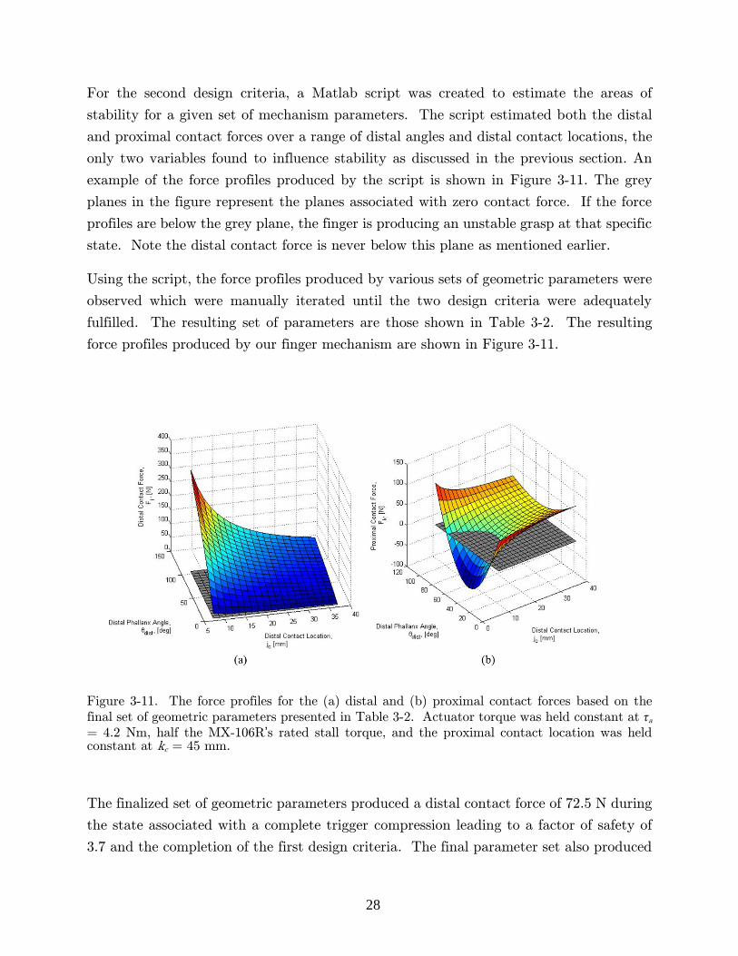
All the contact surfaces located on the gripper were recessed to create channels for rubber
strips to be placed in. The inclusion of these recessed surfaces increased the complexity
of the design greatly due to the limitations associated with CNC machining. At the time
of the design phase, the channels were thought to be necessary to increase the rubber’s
resistance to shear load. Figure 3-14 shows the added complexity needed to incorporate
the recessed surfaces.
Figure 3-14. (a) The design used to create recessed contact surfaces on the four palm plates and (b) the resulting design after assembly.
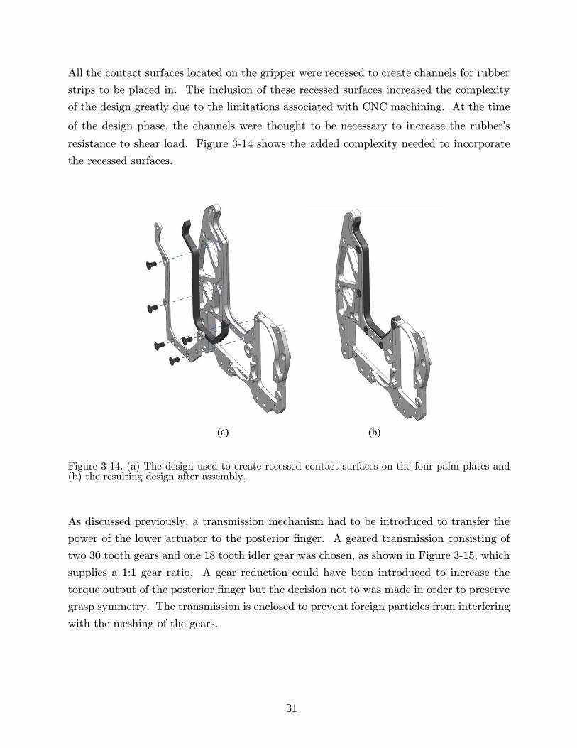
As discussed previously, a transmission mechanism had to be introduced to transfer the
power of the lower actuator to the posterior finger. A geared transmission consisting of
two 30 tooth gears and one 18 tooth idler gear was chosen, as shown in Figure 3-15, which
supplies a 1:1 gear ratio. A gear reduction could have been introduced to increase the
torque output of the posterior finger but the decision not to was made in order to preserve
grasp symmetry. The transmission is enclosed to prevent foreign particles from interfering
with the meshing of the gears.
32
Figure 3-15. A close-up view of the gripper’s gear box. The gearbox cover is made transparent to improve clarity.
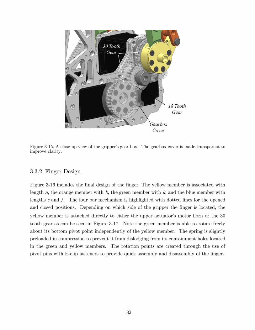
3.3.2 Finger Design
Figure 3-16 includes the final design of the finger. The yellow member is associated with
length a, the orange member with b, the green member with k, and the blue member with
lengths c and j. The four bar mechanism is highlighted with dotted lines for the opened
and closed positions. Depending on which side of the gripper the finger is located, the
yellow member is attached directly to either the upper actuator’s motor horn or the 30
tooth gear as can be seen in Figure 3-17. Note the green member is able to rotate freely
about its bottom pivot point independently of the yellow member. The spring is slightly
preloaded in compression to prevent it from dislodging from its containment holes located
in the green and yellow members. The rotation points are created through the use of
pivot pins with E-clip fasteners to provide quick assembly and disassembly of the finger.
33
Figure 3-16. Multiple views of the Mark I finger design. The dotted lines highlight the four bar mechanism.
Figure 3-17 shows a side view of the gripper with the inner and outer palm plates removed.
The outer palm plate provides the finger with double support by carrying load transferred
through the yellow member’s cylindrical cantilevered extrusion.
Figure 3-17. A side view of the gripper showing how the fingers were slid inwards to reduce the overall width between the fingers. The four palm plates and the gearbox cover are hidden.

34
With the chosen design, a minimum distance between the two mechanism center planes
exists dictated by the widths of the actuator, gear, and motor horn. In order to decrease
the overall width between the outside of the two fingers, the fingers’ center planes were
offset inwards by 4 mm. The slimmer profile is essential to decrease the interferences
experienced when grasping the drill.
Figure 3-18 shows the additional complexity needed to provide recessed contact surfaces
on the finger. The final Mark I design is shown in Figure 3-19. The parts were machined
from 6061 aluminum and the EPDM textured rubber was bonded to the aluminum using
Loctite 380. The gripper is attached to a carbon fiber tube which was used to manually
position and orient the gripper during testing without the use of a robotic arm.
Figure 3-18. The design used to create recessed contact surfaces on the (a) proximal phalanx and (c) distal phalanx. Also shown is the assembled (b) proximal and (d) distal phalanxes.

35
Figure 3-19. The assembled Mark I design.
3.4 Gripper Improvements
After building two grippers and conducting preliminary grasping tests a few potential
areas of improvement became apparent, which would lead to overall better performance
and easier manufacturing. Figure 3-20 shows the resulting Mark II gripper design with
the desired modifications.

36
Figure 3-20. A comparison of the (a) Mark I and (b) Mark II gripper designs.
3.4.1 Omission of Recessed Surfaces
The addition of the recessed contact surfaces in the Mark I design increased the rubber’s
bond strength but dramatically increased the difficulty involved in manufacturing the
gripper. The rubber strips that were used had to be 3.0 mm thick in order to protrude
slightly from the surrounding aluminum. The relatively large thickness of the rubber
made adhering it to rounded surfaces, like those found at the tips of the distal phalanxes,
difficult due to the small bend radii. Furthermore, cutting the rubber strips to fit precisely
into their corresponding channels was difficult and time consuming.
The bonding agent used to adhere the rubber to the aluminum was stronger than
expected. As a result, it was decided to remove the recessed contact surfaces in future
gripper designs as it was realized they added unneeded complexity and that adhering 1.5
mm thick rubber to non-recessed surfaces would suffice instead.
3.4.2 Omission of Outside Palm Plates
The added thickness produced by the outside palm plates made certain tasks difficult to
accomplish due to the interferences between the plates and certain work objects. Also
after building the first set of grippers, it was verified that pinching small objects would
37
not be required in the DRC, making the pinching ability of the Mark I design an
unnecessary feature. To address both issues, the outer plates were removed in favor of
smaller side brackets whose sole purpose is to supply double support to the yellow member
of the fingers.
3.4.3 Increase in Modularity
During early tests, the benefits of a modular design were apparent. The ability to quickly
change the palm shapes and finger shapes would allow testing of new designs quickly and
easily if the need ever arose due to changing circumstances leading up to the DRC.
Modifying the shape of any of the contact surfaces in the Mark I design would involve
extensive machining, disassembly and reassembly. The same is true even if the contact
surfaces just had to be replaced due to wear on the rubber. The Mark II design
incorporates modularity into the phalanxes and also into the pylons as shown in Figure
3-21.
38
Figure 3-21. A display of the modularity incorporated into the (a) finger and (b) pylon.
3.4.4 Increase in Symmetry
Many of the parts were redesigned to utilize the advantages of symmetry. If the gripper
was symmetric about its center plane, which the proposed design is not, the same gripper
could have been used on both the left and right arms. Since the posterior finger is driven
by a gearbox, the design cannot be fully symmetric and therefore a mirrored version of
the gripper had to be created to ensure equal gripper performance and mass properties on
both the left and right arms. As a result, some parts had up to four unique variants in a
single set of grippers, such as with the inside palm plate as shown in Figure 3-22.
39
Figure 3-22. The four variants of the inside palm plate needed to make a left and right handed
gripper using the original Mark I design. (a) Posterior – right gripper, (b) posterior – left gripper,
(c) anterior – right gripper, (d) anterior – left gripper.
A goal of the redesign was to reduce the instances of unique part variants not just between
left and right grippers but also between the posterior and anterior side of a single gripper.
For example, the modular parts presented in Figure 3-21 are fully symmetric meaning
their one design can be used in all four of their instances in a set of grippers.
Through the cumulative effect of the several modifications applied to the Mark II design,
the number of unique aluminum parts for a set of grippers was reduced from 35 to 20,
reducing overall complexity, manufacturing time, and machining costs. The added
symmetry of the new design also allowed a left handed gripper to be reassembled into a
right handed gripper and vice versa without trading out parts; a feature not possible with
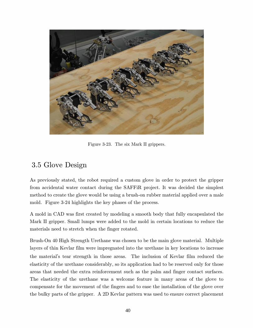
the Mark I design. The mass of the gripper was also reduced 29%, from 0.96 kg to 0.68
kg. As shown in Figure 3-23, altogether, six Mark II grippers were manufactured and
prepared for use on multiple robots.
40
Figure 3-23. The six Mark II grippers.
3.5 Glove Design
As previously stated, the robot required a custom glove in order to protect the gripper
from accidental water contact during the SAFFiR project. It was decided the simplest
method to create the glove would be using a brush-on rubber material applied over a male
mold. Figure 3-24 highlights the key phases of the process.
A mold in CAD was first created by modeling a smooth body that fully encapsulated the
Mark II gripper. Small lumps were added to the mold in certain locations to reduce the
materials need to stretch when the finger rotated.
Brush-On 40 High Strength Urethane was chosen to be the main glove material. Multiple
layers of thin Kevlar film were impregnated into the urethane in key locations to increase
the material’s tear strength in those areas. The inclusion of Kevlar film reduced the
elasticity of the urethane considerably, so its application had to be reserved only for those
areas that needed the extra reinforcement such as the palm and finger contact surfaces.
The elasticity of the urethane was a welcome feature in many areas of the glove to
compensate for the movement of the fingers and to ease the installation of the glove over
the bulky parts of the gripper. A 2D Kevlar pattern was used to ensure correct placement

41
of the Kevlar film during the molding process. The final glove consisted of three layers
of urethane and two thin layers of Kevlar film impregnated inside the urethane in certain
locations.
Figure 3-24. An overview of the process used to create the SAFFiR glove. (a) first a male mold was designed in CAD, (b) the mold was 3D printed in three smaller parts then combined, (c) Kevlar film was applied in certain areas using a custom pattern, and (d) several thin layers of urethane were brushed over the mold and Kevlar.
As can be seen in Figure 3-25, the original Mark II design does not provide enough room
for a glove to fit in-between the finger and inside palm plate. Utilizing the modularity
previously discussed, a slimmer distal phalanx was created to supply more clearance for
use with the glove. Rubber pads were not added on to the slim distal phalanx because
the glove was used to increase the friction on the contact surface.
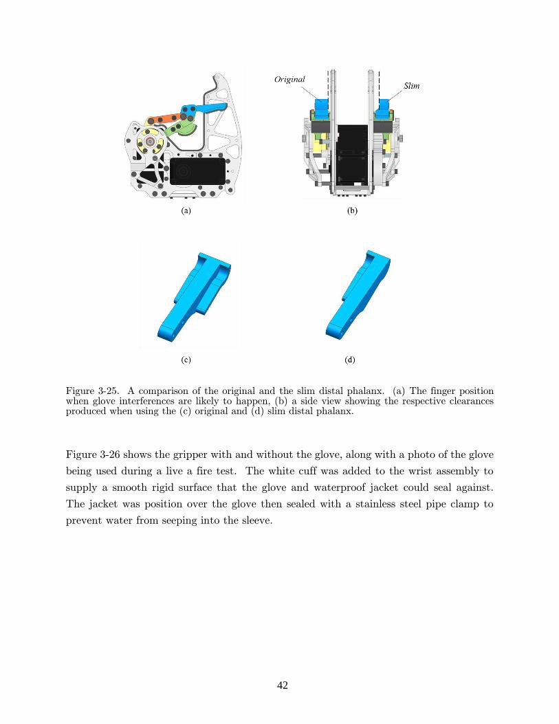
42
Figure 3-25. A comparison of the original and the slim distal phalanx. (a) The finger position when glove interferences are likely to happen, (b) a side view showing the respective clearances produced when using the (c) original and (d) slim distal phalanx.
Figure 3-26 shows the gripper with and without the glove, along with a photo of the glove
being used during a live a fire test. The white cuff was added to the wrist assembly to
supply a smooth rigid surface that the glove and waterproof jacket could seal against.
The jacket was position over the glove then sealed with a stainless steel pipe clamp to
prevent water from seeping into the sleeve.

43
Figure 3-26. A visual of the final SAFFiR glove showing (a) the white cuff, (b) the sealing method used to prevent water seepage, and (c) the glove being used in an actual live-fire test.
44
4 Experiment
The following sections describe the tests used to validate the gripper’s capabilities with
regards to the tasks described in Table 1-1. The first section includes how the tasks were
organized and validated. The next section contains the tests used to determine important
properties of the MX-106R that are vital to conducting and understanding the succeeding
experiments. The later sections provide the four test setups, procedures and results.
4.1 Testing Overview and Organization
The goal of the following tests was to validate whether or not the Mark II gripper was
capable of accomplishing the tasks it was designed to complete. To simplify this goal,
each task was broken down into smaller actions as discussed earlier. Four tests were
developed to validate these actions and their grouping can be seen below in Table 4-1.
Ideally these actions would have been tested on the full robot platform in real working
conditions, but this was not possible at the time. Instead, the testing was performed with
the hand attached to the carbon fiber tube shown previously in Figure 3-19. Using the
tube a human operator manually positioned the hand in the desired locations and
orientations for each test. The benefit of this testing method was that it could be
conducted without the use of the robot and without the need of developing new
manipulation strategies.
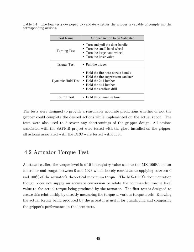
45
Table 4-1. The four tests developed to validate whether the gripper is capable of completing the corresponding actions.
Test Name Gripper Action to be Validated
Turning Test
• Turn and pull the door handle
• Turn the small hand wheel
• Turn the large hand wheel
• Turn the lever valve
Trigger Test • Pull the trigger
Dynamic Hold Test
• Hold the fire hose nozzle handle
• Hold the fire suppressant canister
• Hold the 2x4 lumber
• Hold the 4x4 lumber
• Hold the cordless drill
Instron Test • Hold the aluminum truss
The tests were designed to provide a reasonably accurate predictions whether or not the
gripper could complete the desired actions while implemented on the actual robot. The
tests were also used to discover any shortcomings of the gripper design. All actions
associated with the SAFFiR project were tested with the glove installed on the gripper;
all actions associated with the DRC were tested without it.
4.2 Actuator Torque Test
As stated earlier, the torque level is a 10-bit registry value sent to the MX-106R’s motor
controller and ranges between 0 and 1023 which loosely correlates to applying between 0
and 100% of the actuator’s theoretical maximum torque. The MX-106R’s documentation
though, does not supply an accurate conversion to relate the commanded torque level
value to the actual torque being produced by the actuator. The first test is designed to
create this relationship by directly measuring the torque at various torque levels. Knowing
the actual torque being produced by the actuator is useful for quantifying and comparing
the gripper’s performance in the later tests.

46
4.2.1 Test Setup
Figure 4-1 contains the test setup for the actuator torque test and steady state
temperature test, the latter of which is discussed in the following section. The torque test
consisted of directly measuring the torque output of multiple actuators using an ATI
Mini45 Force/Torque (F/T) Sensor while the multi-meter monitored the ambient
temperature, Tamb.
Figure 4-1. The test setup used for the actuator torque tests and the steady state (SS) temperature test.
The F/T sensor was capable of measuring 6 axis, but the test only utilized the
measurement of force in the z-direction, as shown in Figure 4-2. A bracket was attached
to each actuator to supply a moment arm of known length, ℓm. In order to allow for the
simple calculation of the actuator’s torque, τa, the F/T sensor was placed on an aluminum
base to raise the height of its top surface, h, to the same height as the actuator’s rotation
axis. The torque was measured for three different actuators while increasing the torque
level from 50 to 600 in increments of 50.
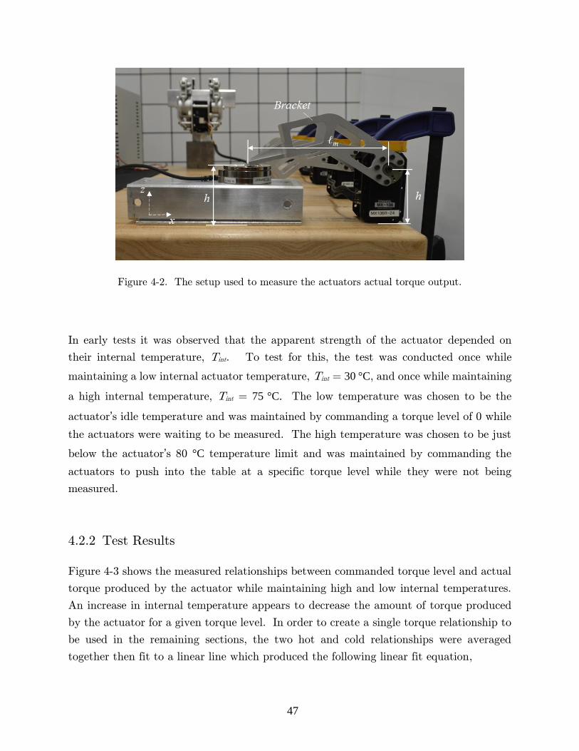
47
Figure 4-2. The setup used to measure the actuators actual torque output.
In early tests it was observed that the apparent strength of the actuator depended on
their internal temperature, Tint. To test for this, the test was conducted once while
maintaining a low internal actuator temperature, Tint = 30 °C, and once while maintaining
a high internal temperature, Tint = 75 °C. The low temperature was chosen to be the
actuator’s idle temperature and was maintained by commanding a torque level of 0 while
the actuators were waiting to be measured. The high temperature was chosen to be just
below the actuator’s 80 °C temperature limit and was maintained by commanding the
actuators to push into the table at a specific torque level while they were not being
measured.
4.2.2 Test Results
Figure 4-3 shows the measured relationships between commanded torque level and actual
torque produced by the actuator while maintaining high and low internal temperatures.
An increase in internal temperature appears to decrease the amount of torque produced
by the actuator for a given torque level. In order to create a single torque relationship to
be used in the remaining sections, the two hot and cold relationships were averaged
together then fit to a linear line which produced the following linear fit equation,

48
𝜏𝑎 = 0.006 𝑄 + 0.0524, [𝑁𝑚] (23)
where Q is the commanded torque level.
Figure 4-3. The measured relationship between the commanded torque level and the actual torque produced by the actuators.
In practice the actuators rarely operate at the extreme internal temperatures tested here
and instead typically operate between 45<Tint<55 °C. As a result, the averaged
relationship presented by Equation 23 will better represent the actual relationship for a
majority of use cases. Equation 23 will be used in the remaining sections to estimate the
torque being produced for a given torque level.
4.3 Actuator Steady State Temperature Test
The actuator’s temperature limiting safety feature was left intact, meaning the gripper
could experience an unplanned motor shutdown if the internal temperature of the
actuators exceeds 80 °C. This second actuator test was designed to determine the largest
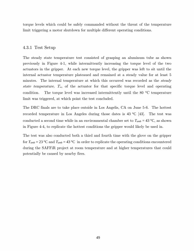
49
torque levels which could be safely commanded without the threat of the temperature
limit triggering a motor shutdown for multiple different operating conditions.
4.3.1 Test Setup
The steady state temperature test consisted of grasping an aluminum tube as shown
previously in Figure 4-1, while intermittently increasing the torque level of the two
actuators in the gripper. At each new torque level, the gripper was left to sit until the
internal actuator temperature plateaued and remained at a steady value for at least 5
minutes. The internal temperature at which this occurred was recorded as the steady
state temperature, Tss, of the actuator for that specific torque level and operating
condition. The torque level was increased intermittently until the 80 °C temperature
limit was triggered, at which point the test concluded.
The DRC finals are to take place outside in Los Angelis, CA on June 5-6. The hottest
recorded temperature in Los Angeles during those dates is 43 °C [43]. The test was
conducted a second time while in an environmental chamber set to Tamb = 43 °C, as shown
in Figure 4-4, to replicate the hottest conditions the gripper would likely be used in.
The test was also conducted both a third and fourth time with the glove on the gripper
for Tamb = 23 °C and Tamb = 43 °C in order to replicate the operating conditions encountered
during the SAFFiR project at room temperature and at higher temperatures that could
potentially be caused by nearby fires.
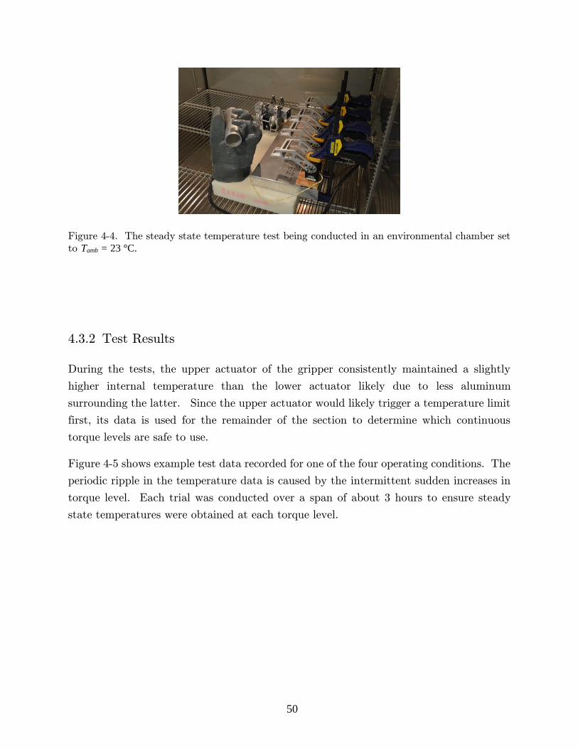
50
Figure 4-4. The steady state temperature test being conducted in an environmental chamber set
to Tamb = 23 °C.
4.3.2 Test Results
During the tests, the upper actuator of the gripper consistently maintained a slightly
higher internal temperature than the lower actuator likely due to less aluminum
surrounding the latter. Since the upper actuator would likely trigger a temperature limit
first, its data is used for the remainder of the section to determine which continuous
torque levels are safe to use.
Figure 4-5 shows example test data recorded for one of the four operating conditions. The
periodic ripple in the temperature data is caused by the intermittent sudden increases in
torque level. Each trial was conducted over a span of about 3 hours to ensure steady
state temperatures were obtained at each torque level.

51
Figure 4-5. Example data from the steady state temperature test for the operating condition, Tamb
= 23 °C with the glove off.
Figure 4-6 shows steady state temperatures recorded at each torque level for the four
operating conditions. The idle temperature of the actuator is roughly 10 °C higher when
the ambient temperature is increased from 23 to 43 °C. As expected, installing the glove
produces higher overall internal temperatures.
0 0.5 1 1.5 2 2.5 3 3.5 430
40
50
60
70
80
Time [hours]
Inte
nal M
oto
r T
em
pera
ture
, T in
t [C
]
Upper Gripper Motor
Lower Gripper Motor
0 0.5 1 1.5 2 2.5 3 3.5 4-100
0
100
200
300
400
Time [hours]
Com
manded T
orq
ue L
evel, Q
52
Figure 4-6. The measured steady state temperatures of the actuator at various torque levels for the four different operating conditions. The top most points are used as the nominal torque level for the actuator for that operating condition.
As seen in the bottom of Figure 4-5, the upper actuator triggered the temperature limit
when its torque level was increased to 340. The torque level commanded beforehand,
320, was then recorded as the nominal torque level for the gripper in that specific operating
condition.
Table 4-2 presents the four measured nominal torque levels along with a summary of other
important values. For simplicity a single recommended torque level for use with the DRC
and another for use with the SAFFiR project was calculated. The values were produced
by applying a 1.33 factor of safety to the nominal torque levels at Tamb = 43C.
0 50 100 150 200 250 300 35020
30
40
50
60
70
80
Commanded Torque Level, Q
Ste
ady S
tate
Inte
rnal M
oto
r T
em
pera
ture
, T in
t [C
]
23 C Ambient Temp., No Glove
23 C Ambient Temp., Glove
43 C Ambient Temp., No Glove
43 C Ambient Temp., Glove

53
Table 4-2. A summary of the important torque level values of the actuators. The actual produced torque is estimated using Equation 23 and is shown in parenthesis.
Description
Torque Level
(Actual Torque)
DRC -
No Glove
SAFFiR -
Glove
Theoretical Maximum
Torque Level
The largest possible commandable torque
level, irreversible thermal damage will
likely be sustained before the temperature
limit is triggered
1023
(6.2 Nm)
1023
(6.2 Nm)
Maximum
Torque Level
Maximum torque level that can be safely
applied intermittently for short periods of
time, the temperature limit will eventually
trigger
500
(3.1 Nm)
500
(3.1 Nm)
Nominal
Torque Level
(Room Temperature)
Maximum torque level that can be safely
applied continuously for extended periods
of time without triggering the temperature
limit when, Tamb = 23 °C
320
(2.0 Nm)
270
(1.7 Nm)
Nominal
Torque Level
(Hot Temperature)
Maximum torque level that can be safely
applied continuously for extended periods
of time without triggering the temperature
limit when, Tamb = 43 °C
270
(1.7 Nm)
200
(1.3 Nm)
Recommended
Torque Level
Maximum torque level that should be
applied to achieve a reasonable factor of
safety against triggering the temperature
limit
200
(1.3 Nm)
150
(1.0 Nm)
All of the remaining tests were conducted with the actuators set at the recommended
torque levels unless otherwise stated. Note the recommended values are quite conservative
and the actuators can indeed be safely set to much higher torque levels for short periods
of time.

54
4.4 Turning Test
The following tests were designed to determine whether the gripper is capable of applying
the necessary forces needed to induce rotation without slipping for the actions specified
previously in Figure 4-1.
4.4.1 Test Setup
The DRC documentation specifies that the valves will require no more than 22.2 N [5 lbf]
applied at their furthest radius to rotate them [44]. Table 4-3 shows the estimated torque
required to rotate the valves based on the given information.
Table 4-3. A summary of the required forces and torques needed to accomplish the corresponding actions. Note the only action requiring additional pull force is the door handle because it must be pulled open after turning it.
Work Object
Furthest Radius
from Rotation Axis
[mm]
Force Required at
Furthest Radius to
Induce Rotation
[N]
Estimated Torque
Required to
Induce Rotation
[Nm]
Additional Pull
Force Required to
Accomplish
Action
[N]
Door handle 101.6 9.3 0.9 28.2
Large Hand Wheel 228.6 22.2 5.1 ---
Small Hand Wheel 114.3 22.2 2.5 ---
Lever Valve 330.2 22.2 7.3 ---
Specifications for the door handle were not supplied in the DRC documentation. To
gather the needed criteria, a relatively large door in our laboratory was measured which
is shown in Figure 4-7. Using a luggage scale the force required to rotate the handle and
the force required to pull the door open using the handle were both measured. The
resulting measurements can be found in the above table. The door was heavily weighted
to shut close so these measurements are thought to be similar to worse case scenarios.

55
Figure 4-7. (a) The door used to measure the missing door handle criteria, (b) the method used for measuring the torque required to rotate the handle, and (c) the method used to measure the pull force required to open the door.
Figure 4-8 shows the measuring device used during these tests. The same F/T sensor
used previously is used again here. The F/T sensor was bolted in between a mounting
block and rigid vertical plate. A threaded rod was screwed into the mounting block, then
a nut was tightened to clamp the work object in between the clamping cylinder and
mounting block; effectively constraining the work object to the stationary F/T sensor. In
this configuration the work object could not rotate, but any force or torque applied to it
could be measured by the F/T sensor.

56
Figure 4-8. The measuring device used in the turning test.
Using the carbon fiber tube, the operator positioned the gripper in a desired grasp
orientation, then the fingers were closed and the operator applied force to the work object
through the gripper until the grasp slipped or until the operator could not physically
apply any further force. The F/T sensor was used to record the torque and pull force
applied to the work object during each trial.
Slippage caused spikes in the measured data which tended to falsely skew the results since
the maximum torque and maximum force were the metrics used to validate the gripper’s
performance. If slippage occurred, the trial was redone with less force applied by the
operator until slippage was completely avoided.
The tests consisted of arranging the gripper in the five grasping orientations shown in
Figure 4-9. The gripper was purposefully positioned to prevent the rigid parts of the
gripper from contacting the inner spokes of the hand wheel, allowing the quality of the
grasp to be more accurately evaluated. The hand wheel valves were tested using two
grasp orientations: a tradition radial grasp and a more nontraditional axial grasp. The
non-traditional axial grasp allows the valve to be turned by simply rotating the wrist’s
yaw actuator, while the traditional radial grasp requires a complex arm movement. The
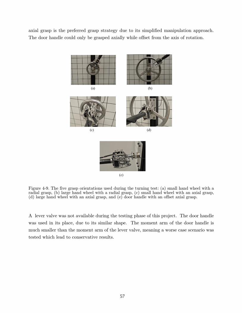
57
axial grasp is the preferred grasp strategy due to its simplified manipulation approach.
The door handle could only be grasped axially while offset from the axis of rotation.
Figure 4-9. The five grasp orientations used during the turning test: (a) small hand wheel with a radial grasp, (b) large hand wheel with a radial grasp, (c) small hand wheel with an axial grasp, (d) large hand wheel with an axial grasp, and (e) door handle with an offset axial grasp.
A lever valve was not available during the testing phase of this project. The door handle
was used in its place, due to its similar shape. The moment arm of the door handle is
much smaller than the moment arm of the lever valve, meaning a worse case scenario was
tested which lead to conservative results.

58
4.4.2 Test Results
Figure 4-10 shows an example of the F/T sensor data for the door handle action. As can
be seen, the door handle was turned and pulled simultaneously, resulting in a peak torque
of 10.0 Nm and peak pull force of 187 N. When compared to the required values from
Table 4-3, the factor safeties associated with the torque and pull force are found to be
10.7 and 6.6 respectfully.
Figure 4-10. Example data measured by the F/T sensor while validating the door handle action with an offset axial grasp.
The F/T sensor data from the other trials can be found in Appendix A. The main results
for all six trials are shown below in Table 4-4. All six trials produced factors of safety
greater than 1.0, meaning the gripper should in fact be capable of completing the four
actions even when using the preferred axial grasping method.
0 2 4 6 8 10 12 14 16 18-200
-150
-100
-50
0
50
100
150
200
Time [sec]
Pull
Forc
e [
N]
0 2 4 6 8 10 12 14 16 18-20
-15
-10
-5
0
5
10
15
20
Torq
ue [
Nm
]
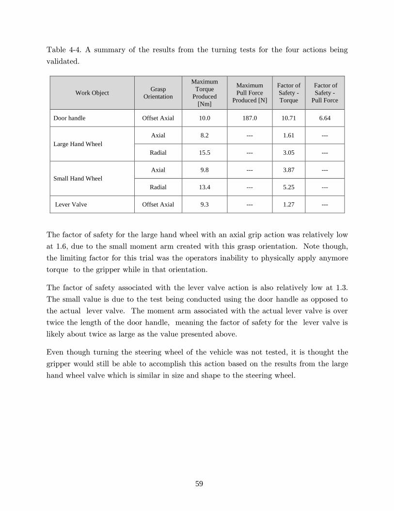
59
Table 4-4. A summary of the results from the turning tests for the four actions being
validated.
Work Object Grasp
Orientation
Maximum
Torque
Produced
[Nm]
Maximum
Pull Force
Produced [N]
Factor of
Safety -
Torque
Factor of
Safety -
Pull Force
Door handle Offset Axial 10.0 187.0 10.71 6.64
Large Hand Wheel
Axial 8.2 --- 1.61 ---
Radial 15.5 --- 3.05 ---
Small Hand Wheel
Axial 9.8 --- 3.87 ---
Radial 13.4 --- 5.25 ---
Lever Valve Offset Axial 9.3 --- 1.27 ---
The factor of safety for the large hand wheel with an axial grip action was relatively low
at 1.6, due to the small moment arm created with this grasp orientation. Note though,
the limiting factor for this trial was the operators inability to physically apply anymore
torque to the gripper while in that orientation.
The factor of safety associated with the lever valve action is also relatively low at 1.3.
The small value is due to the test being conducted using the door handle as opposed to
the actual lever valve. The moment arm associated with the actual lever valve is over
twice the length of the door handle, meaning the factor of safety for the lever valve is
likely about twice as large as the value presented above.
Even though turning the steering wheel of the vehicle was not tested, it is thought the
gripper would still be able to accomplish this action based on the results from the large
hand wheel valve which is similar in size and shape to the steering wheel.
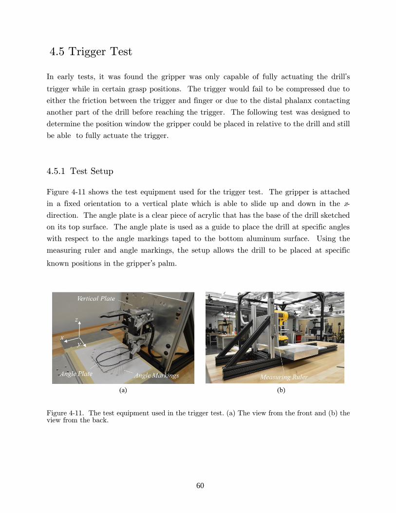
60
4.5 Trigger Test
In early tests, it was found the gripper was only capable of fully actuating the drill’s
trigger while in certain grasp positions. The trigger would fail to be compressed due to
either the friction between the trigger and finger or due to the distal phalanx contacting
another part of the drill before reaching the trigger. The following test was designed to
determine the position window the gripper could be placed in relative to the drill and still
be able to fully actuate the trigger.
4.5.1 Test Setup
Figure 4-11 shows the test equipment used for the trigger test. The gripper is attached
in a fixed orientation to a vertical plate which is able to slide up and down in the z-
direction. The angle plate is a clear piece of acrylic that has the base of the drill sketched
on its top surface. The angle plate is used as a guide to place the drill at specific angles
with respect to the angle markings taped to the bottom aluminum surface. Using the
measuring ruler and angle markings, the setup allows the drill to be placed at specific
known positions in the gripper’s palm.
Figure 4-11. The test equipment used in the trigger test. (a) The view from the front and (b) the view from the back.
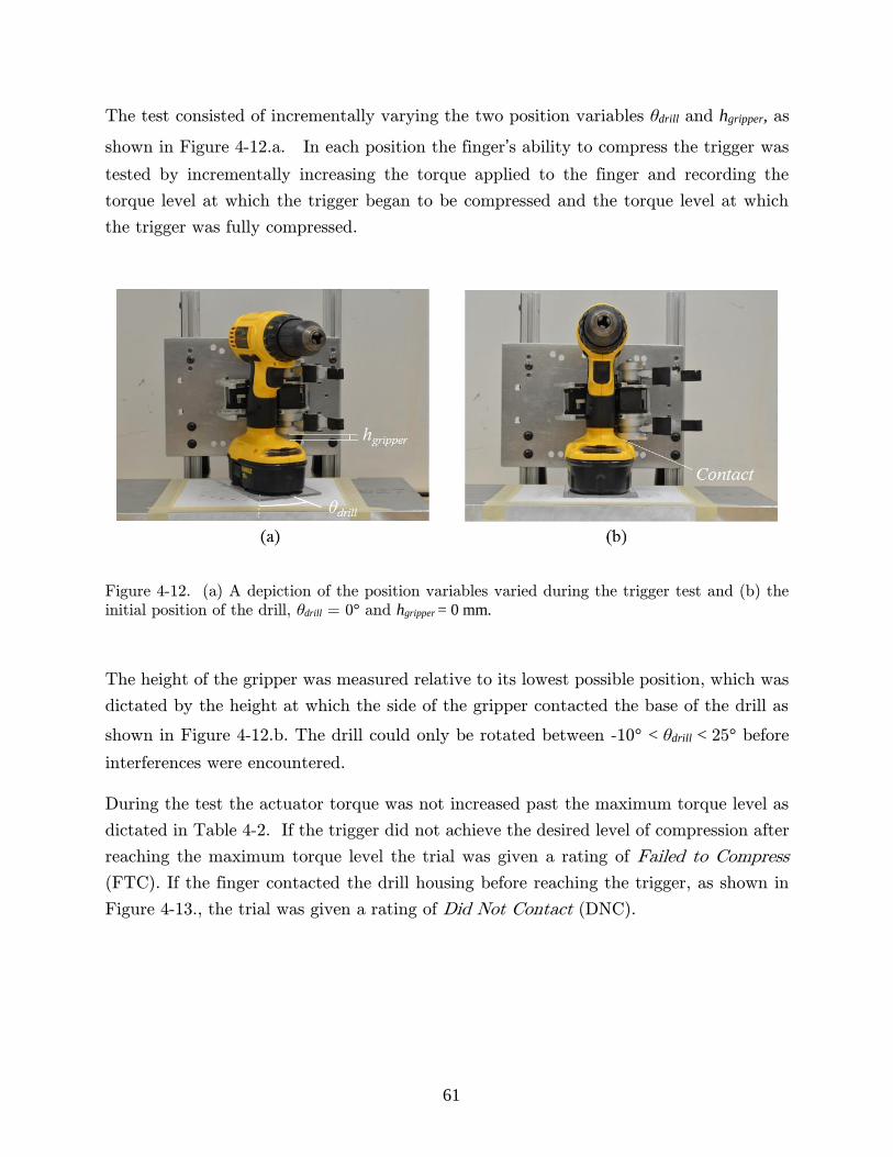
61
The test consisted of incrementally varying the two position variables θdrill and hgripper, as
shown in Figure 4-12.a. In each position the finger’s ability to compress the trigger was
tested by incrementally increasing the torque applied to the finger and recording the
torque level at which the trigger began to be compressed and the torque level at which
the trigger was fully compressed.
Figure 4-12. (a) A depiction of the position variables varied during the trigger test and (b) the
initial position of the drill, θdrill = 0° and hgripper = 0 mm.
The height of the gripper was measured relative to its lowest possible position, which was
dictated by the height at which the side of the gripper contacted the base of the drill as
shown in Figure 4-12.b. The drill could only be rotated between -10° < θdrill < 25° before
interferences were encountered.
During the test the actuator torque was not increased past the maximum torque level as
dictated in Table 4-2. If the trigger did not achieve the desired level of compression after
reaching the maximum torque level the trial was given a rating of Failed to Compress
(FTC). If the finger contacted the drill housing before reaching the trigger, as shown in
Figure 4-13., the trial was given a rating of Did Not Contact (DNC).

62
Figure 4-13. A comparison of the resulting trigger pulls from using (a) the original distal phalanx and the (b) the slim distal phalanx. The original phalanx contacts the drill housing while the slim phalanx successfully compresses the trigger.
Early in testing it was realized that using the slim distal phalanx, created previously for
the SAFFiR glove, was more effective at actuating the trigger because it was thinner and
did not have rubber on its contact surface. Figure 4-13. contains an example of how the
slim phalanx leads to more successful trigger pulls. The lack of rubber allowed the finger
to slide more easily along the trigger due to less friction. For comparison, the trigger test
was conducted once with the original phalanx and once with the slim phalanx.
4.5.2 Test Results
The results of the trigger test are presented on the following page in Table 4-5. A lower
required torque generally indicates a more effective and favorable grasp position. As can
be seen from the results, grasping the drill with a positive rotation about the z-axis is
generally more favorable than a grasping it with a negative one.
The use of the slim distal phalanx resulted in better overall performance. The number of
positions which allowed the finger to initiate the trigger was increased from 14 to 28 and
the number of positions which allowed the finger to fully compress the trigger was
increased from 11 to 21 by replacing the original phalanx with the slim phalanx. In most
positions the slim phalanx also required less torque.

63
Table 4-5. The torque required to initiate and to complete trigger actuation while using the original and the slim distal phalanx for various positions. The actual torque is estimated using Equation 23 and is shown in parenthesis with units [Nm].
Original Phalanx - Torque required to Initiate Trigger Original Phalanx - Torque required to Fully Compress Trigger
Drill Angle, θdrill [°] Drill Angle, θdrill [°]
-10 -5 0 5 10 15 20 25 -10 -5 0 5 10 15 20 25
Gri
pp
er H
eig
ht,
h
gri
pper
[m
m]
16 DNC DNC DNC DNC DNC DNC DNC DNC
Gri
pp
er H
eig
ht,
h
gri
pper
[m
m]
16 DNC DNC DNC DNC DNC DNC DNC DNC
12 DNC DNC DNC DNC DNC DNC DNC DNC 12 DNC DNC DNC DNC DNC DNC DNC DNC
8 FTC FTC FTC FTC 500
(3.1)
420
(2.6)
320
(2.0)
300
(1.9) 8 FTC FTC FTC FTC FTC
480
(2.9)
380
(2.3)
360
(2.2)
4 FTC FTC FTC 400
(2.5)
300
(1.9)
240
(1.5)
220
(1.4)
180
(1.1) 4 FTC FTC FTC FTC
380
(2.3)
320
(2.0)
260
(1.6)
240
(1.5)
0 FTC FTC FTC 400
(2.5)
280
(1.7)
180
(1.1)
160
(1.0)
160
(1.0) 0 FTC FTC FTC FTC
460
(2.3)
300
(1.9)
260
(1.6)
260
(1.6)
Slim Phalanx - Torque required to Initiate Trigger Slim Phalanx - Torque required to Fully Compress Trigger
Drill Angle, θdrill [°] Drill Angle, θdrill [°]
-10 -5 0 5 10 15 20 25 -10 -5 0 5 10 15 20 25
Gri
pp
er H
eig
ht,
h
gri
pp
er [
mm
]
16 DNC DNC DNC DNC DNC DNC DNC DNC
Gri
pp
er H
eig
ht,
h
gri
pp
er [
mm
]
16 DNC DNC DNC DNC DNC DNC DNC DNC
12 FTC 480
(2.9)
360
(2.2) FTC
360
(2.2)
320
(2.0)
260
(1.6)
280
(1.7) 12 FTC FTC FTC FTC
400
(2.5)
360
(2.2)
320
(2.0)
320
(2.0)
8 440
(2.7)
360
(2.2) FTC
300
(1.9)
260
(1.6)
220
(1.4)
220
(1.4)
180
(1.1) 8 FTC FTC FTC
380
(2.3)
300
(1.9)
260
(1.6)
240
(1.5)
240
(1.5)
4 380
(2.3)
300
(1.9)
340
(2.1)
260
(1.6)
220
(1.4)
160
(1.0)
140
(0.9)
140
(0.9) 4 FTC FTC
380
(2.3)
300
(1.9)
240
(1.5)
240
(1.5)
220
(1.4)
220
(1.4)
0 460
(2.3) FTC
400
(2.5)
220
(1.4)
180
(1.1)
140
(0.9)
140
(0.9)
120
(0.8) 0
460
(2.3) FTC
400
(2.5)
280
(1.7)
240
(1.5)
220
(1.4)
240
(1.5)
220
(1.4)

64
The difference in performance between the two fingers can be attributed to the
thinner width of the slim phalanx and also the absence of rubber from its contact
surface. The finger needs to slide along the trigger as it is compressed, so omitting
the rubber from the distal phalanx decreases the sliding resistance produced by
friction.
In order to ensure full trigger compression, the drill must be grasped in the position
window defined by 15 < θdrill < 25° and 0 < hgripper < 8 mm when using the original
distal phalanx and 10 < θdrill < 25° and 0 < hgripper < 12 mm when using the slim distal
phalanx. When using the drill it is recommended to use the slim phalanx because
its corresponding position window is roughly 125% larger and thus more robust to
inaccuracies in manipulation.
Although the position windows may appear small, they only represent the windows
associated with a horizontal drill as shown in Figure 4-14a. The drill can also be
tilted back in the gripper’s palm and in this orientation the finger is placed in a
more optimal position for trigger pulling. As an example, the torque required to
fully compress the trigger at θdrill = 0° and hgripper = 8 mm was 2.7 Nm when
horizontal compared to 1.7 Nm when tilted back as in Figure 4-14b. A full range
of tests were not completed with the drill in the tilted back orientation due to the
added difficulties associated with accurately orientating the drill while in this
orientation. The results presented above in Table 4-5 are considered conservative
since the tests were conducted in a performance limiting orientation.
Figure 4-14. (a) The drill horizontal as it was during the trigger tests and (b) the drill tilted back which leads to more effective trigger actuation.
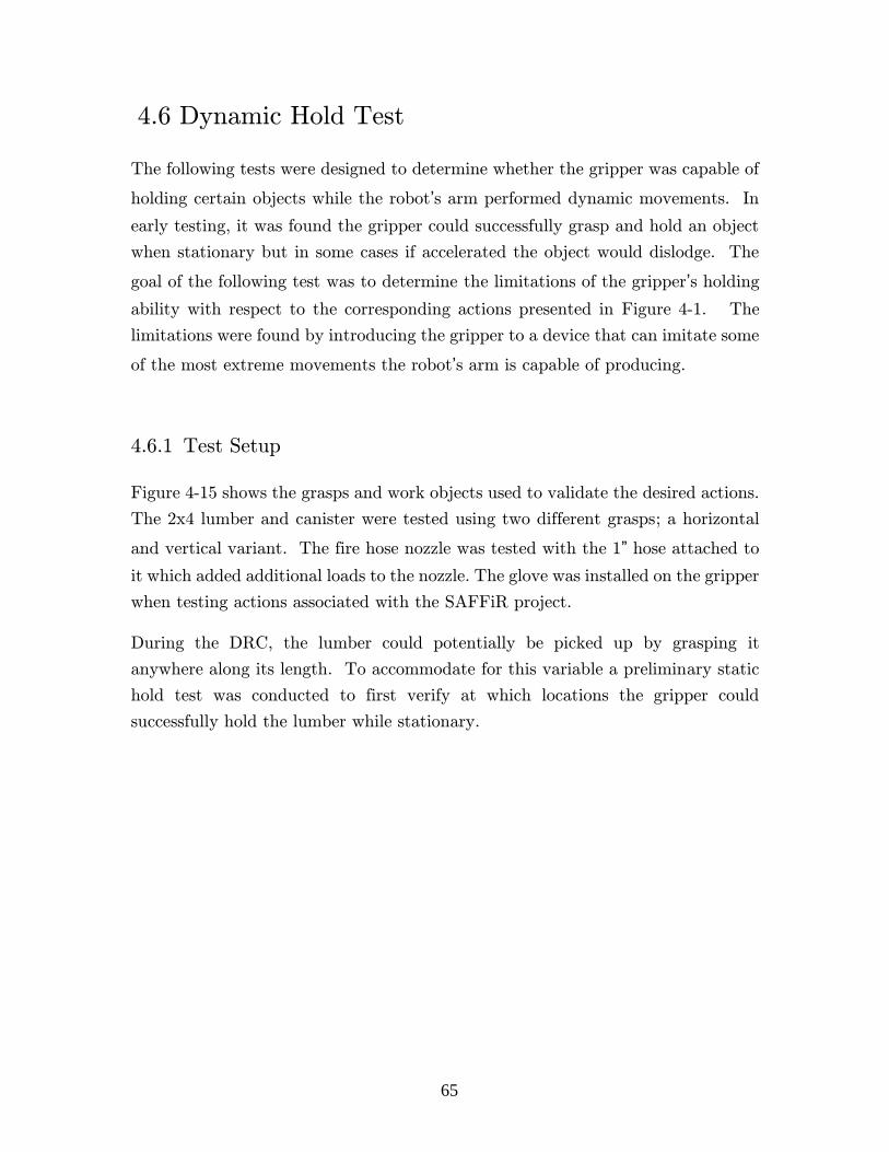
65
4.6 Dynamic Hold Test
The following tests were designed to determine whether the gripper was capable of
holding certain objects while the robot’s arm performed dynamic movements. In
early testing, it was found the gripper could successfully grasp and hold an object
when stationary but in some cases if accelerated the object would dislodge. The
goal of the following test was to determine the limitations of the gripper’s holding
ability with respect to the corresponding actions presented in Figure 4-1. The
limitations were found by introducing the gripper to a device that can imitate some
of the most extreme movements the robot’s arm is capable of producing.
4.6.1 Test Setup
Figure 4-15 shows the grasps and work objects used to validate the desired actions.
The 2x4 lumber and canister were tested using two different grasps; a horizontal
and vertical variant. The fire hose nozzle was tested with the 1” hose attached to
it which added additional loads to the nozzle. The glove was installed on the gripper
when testing actions associated with the SAFFiR project.
During the DRC, the lumber could potentially be picked up by grasping it
anywhere along its length. To accommodate for this variable a preliminary static
hold test was conducted to first verify at which locations the gripper could
successfully hold the lumber while stationary.
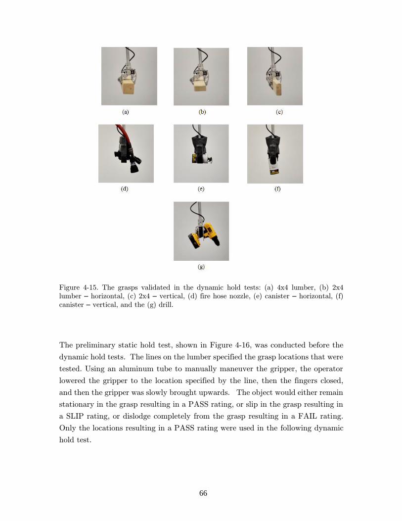
66
Figure 4-15. The grasps validated in the dynamic hold tests: (a) 4x4 lumber, (b) 2x4
lumber – horizontal, (c) 2x4 – vertical, (d) fire hose nozzle, (e) canister – horizontal, (f)
canister – vertical, and the (g) drill.
The preliminary static hold test, shown in Figure 4-16, was conducted before the
dynamic hold tests. The lines on the lumber specified the grasp locations that were
tested. Using an aluminum tube to manually maneuver the gripper, the operator
lowered the gripper to the location specified by the line, then the fingers closed,
and then the gripper was slowly brought upwards. The object would either remain
stationary in the grasp resulting in a PASS rating, or slip in the grasp resulting in
a SLIP rating, or dislodge completely from the grasp resulting in a FAIL rating.
Only the locations resulting in a PASS rating were used in the following dynamic
hold test.

67
Figure 4-16. The preliminary static hold test. (a) The gripper is lowered to the desired location and (b) the gripper is closed and brought slowly upwards. (c) The multiple locations at which the grasp was tested.
The swing arm test was designed to replicate the motion of the gripper produced
when the robot’s arm is fully extended and rotated about the shoulder joint at its
fastest possible velocity. The resulting motion is thought to replicate one of the
most extreme movements the gripper can be placed in while attached to the robot.
Figure 4-17a shows the equipment used to generate this motion. The counter
weight was clamped to a table top while the swing arm protruded off to the side
allowing it to swing unobstructed. The gripper was attached to the end of the
aluminum tube which was adjusted to ensure the length, ℓarm = 645 mm, was the
same distance on the swing arm as it is on the robot as shown in Figure 4-17b and
c. The same actuator used in the robot’s shoulder, the Dynamixel Pro 200W, was
also used on the test equipment to rotate the swing arm. During testing the
actuator was commanded to rotate at its fastest possible velocity.

68
Figure 4-17. (a) The test equipment used in the dynamic hold test, (b) the robot’s actual arm, (c) the swing arm in the long configuration, and (d) the swing arm in the short configuration.
Starting in the position shown above, each trial consisted of rotating the swing arm
up and down twice through the angles 0 < θarm < 90° as depicted in Figure 4-18.
The same PASS, SLIP, or FAIL rating system used previously for the static hold
test was utilized again for rating the dynamic hold test. The test was conducted
once with a long swing arm, ℓarm = 645 mm, and then once with a short swing arm,
ℓarm = 105 mm, as shown in Figure 4-17d. The short swing arm was used to
replicate other extreme movements the gripper could experience, such as quick
flicks of the robot’s wrist. Each of the grasping scenarios shown above in Figure
4-15 was tested in four separate trials for each of the four arm orientations shown
in Figure 4-19.

69
Figure 4-18. An example of one of the trials conducted during the dynamic hold test. This specific trial was for the 4x4 lumber with the long swing arm in arm orientation B.
Figure 4-19. The four arm orientations relative to the swing direction. (a) Arm Orientation A, (b) Arm Orientation B, (c) Arm Orientation C, and (d) Arm Orientation D

70
4.6.2 Test Results
Table 4-6 presents the results from the preliminary static hold test. Location 1
was the only location for all three grasp scenarios which lead to a successful grasp
with no slippage. As a result, only Location 1 was tested in the dynamic hold test.
Table 4-6. The results from the preliminary static hold test.
Grasp Location
Object 1 2 3 4
4x4 Lumber Pass Slip Fail ---
2x4 Lumber - Horizontal Pass Slip Slip Slip
2x4 Lumber - Vertical Pass Slip Fail Fail
As depicted in Figure 4-20, the failures were due to the gripper’s inability to provide
enough torque about the pivot point to counteract the moment generated by the
weight of the lumber, W.
Figure 4-20. A visual of the moment generated by the offset weight of the lumber.
As shown in Figure 4-21, the fingers were not able to wrap around the bottom of
the lumber for any of the three grasping scenarios, meaning the only forces that
provided counteractive torques about the pivot point were produced through
friction instead of stronger normal forces. Extending the fingers so they could wrap
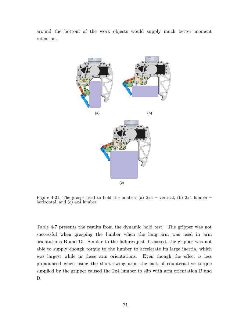
71
around the bottom of the work objects would supply much better moment
retention.
Figure 4-21. The grasps used to hold the lumber: (a) 2x4 – vertical, (b) 2x4 lumber – horizontal, and (c) 4x4 lumber.
Table 4-7 presents the results from the dynamic hold test. The gripper was not
successful when grasping the lumber when the long arm was used in arm
orientations B and D. Similar to the failures just discussed, the gripper was not
able to supply enough torque to the lumber to accelerate its large inertia, which
was largest while in these arm orientations. Even though the effect is less
pronounced when using the short swing arm, the lack of counteractive torque
supplied by the gripper caused the 2x4 lumber to slip with arm orientation B and
D.

72
Table 4-7. The results from the dynamic hold test.
Short Arm,
ℓarm = 105 mm
Long Arm,
ℓarm = 645 mm
Arm Orientation
Object A B C D A B C D
4x4 Lumber Pass Pass Pass Pass Pass Fail Pass Fail
2x4 Lumber - Horizontal Pass Slip Pass Slip Pass Fail Pass Fail
2x4 Lumber - Vertical Pass Pass Pass Pass Pass Slip Pass Slip
Fire Hose Nozzle Pass Slip Pass Pass Pass Pass Pass Pass
Canister - Vertical Pass Pass Pass Pass Pass Pass Pass Pass
Canister - Horizontal Slip Slip Pas Pass Fail Fail Pass Pass
Drill Pass Pass Pass Pass Pass Pass Pass Pass
The hose nozzle was dislodged in one trial due to the hose kinking which applied a
large torque to the nozzle. The gripper had difficulty holding the canister while it
was horizontal. A possible explanation for the difficulty is thought to be caused
by the glove sliding off of the gripper. When attached to the robot, the glove is
secured by the pipe clamp around the white cuff as shown previously in Figure
3-26. The glove was not secured during the dynamic hold tests meaning the glove
could easily slide off if the fingers were not sufficiently curled.
The results from the static and dynamic hold tests are not ideal. A possible
performance improvement could come from increasing the actuator’s torque to
either the nominal torque level or even the maximum torque level which is safe to
apply for short periods of time. Evidence of this improvement was found by
retesting the 4x4 lumber with arm orientation B while the actuator’s torque was
increased to the nominal level of 270 (1.7 Nm) as opposed to the original
recommended level of 200 (1.3 Nm). Originally this specific trial resulted in a
FAIL as depicted above in Figure 4-18 but with the increased torque, the trial
resulted in a PASS.
If the actuators remain at the lower recommended torque levels, slippage and object
dislodgment could be also reduced by avoiding the grasp scenarios that did not
succeed, such as raising the lumber with arm orientations B or D. Another method
of reducing failure rates is to simply limit the speed of the robot’s arm and avoid
the extreme movements that were tested above as much as possible.

73
4.7 Instron Test
As shown previously in Figure 4-1, the following test were designed to determine
the gripper’s ability to perform actions associated with grasping cylindrical objects,
such as the aluminum truss. Since the aluminum truss was not available at the
time of testing, an Instron Universal Testing Machine was used to measure the
gripper’s overall grasping performance related to cylindrical objects. The results
were then used to predict whether the gripper was capable of holding the truss and
also to predict the gripper’s capabilities with regard to other potentially useful
although not required actions, such as using handrails to support the robot while
doing other tasks.
4.7.1 Test Setup
The trials were performed with an Instron 5984 Floor Model, which can be seen in
the test setup in Figure 4-22a. Figure 4-22b shows the aluminum cylinders used
during the tests whose diameters are presented in Table 4-8. Each trial consisted
of first lowering the cylinder to the bottom of the gripper’s palm, closing the fingers,
then raising the cylinder upwards forcing the gripper to open while recording data
about the evolution of the grasp. The Instron was used in position control and
commanded to move upwards at a speed of 10 mm/min.

74
Figure 4-22. (a) The Instron test setup and (b) the hollow aluminum cylinders that were tested.
Table 4-8. The diameters of the cylinders tested.
Cylinder
#
Outer
Diameter
[in]
Outer
Diameter
[mm]
1 0.75 19.1
2 1.25 31.8
3 1.75 44.5
4 3.00 76.2
The test was performed with the two different cylinder constraining methods shown
in Figure 4-23. The first method fully constrained the cylinder creating a setup
referred to as a the fixed cylinder, and the second method allowed the cylinder to
pivot along a hinge axis creating a setup referred to as a the hinged cylinder. The
mounting block was clamped between the jaws of the Instron in both methods.

75
Figure 4-23. The two cylinder constraining methods used in testing; (a) the fixed cylinder method and (b) the hinged cylinder method.
A custom articulated arm attachment was used to secure the gripper to the base
of the Instron as shown in Figure 4-24. The articulated arm allowed the gripper
to move freely in the x and y-directions and rotate freely about the z-axis. By not
constraining those three DOF, the gripper is allowed to naturally evolve its grip as
the cylinder moves upwards resulting in a more realistic grasp. The gripper’s torque
level was limited to 50 (0.4 Nm) instead of the recommended value of 200 (1.3 Nm)
for these tests in order to prevent damaging the articulated arm by limiting the
load applied to it.

76
Figure 4-24. The articulated arm used to allow the gripper to move freely during the Instron test.
As the Intron pulled the cylinder upwards, a computer recorded the downward
force applied to the mounting block and the position of the mounting block relative
to its starting location; the two measurements are referred to as the load, L, and
the extension, dext, respectively. Figure 4-25 contains the states of the grasps
midway through a trial. The hinged cylinder would rotate about a single pivot
point on the edge of the palm as shown in the figure because the gripper was
allowed to freely slide side to side. When positioning the hinged cylinder, the
gripper was placed so the hinge axis started at the same distance, ℓcyl = 120 mm,
from the pivot point for each trial.

77
Figure 4-25. The grasp development midway through (a) a fixed cylinder trial and (b) a hinged cylinder trial.
4.7.2 Test Results
The main result from this test is the maximum load that can be applied to the
cylinder before it is dislodged from the gripper’s grasp. The load required to pull
the cylinder upwards tends to increase as it moves further away from the gripper,
meaning the maximum load could occur when the cylinder is a large distance away
from the bottom of the palm. In practice, though, a large distance may not be
tolerable.
To compensate the variable, dmax, was introduced which was the maximum
extension allowed before the tube is considered to be dislodged. Our performance
metric for this test, referred to as Lmax, is then defined as the maximum load applied
to the cylinder while dext < dmax. For our test, a value of dmax = 4 mm was chosen,
which seemed to be a reasonable extension that the robot could tolerate during
most manipulation tasks.
Figure 4-26 includes the results from the fixed and hinged cylinder trials. The
black line represents dext = dmax. The small black circles mark the locations of the
maximum loads.
78
Figure 4-26. The results of the Instron test with the (a) fixed cylinder and (b) hinged cylinder.
As extension increased the cylinder moved upwards in the palm causing the fingers
to slowly open as their two contact points slid along the outside of the cylinder.
The evolution of the contact force vectors, specifically their direction and
orientation, caused the variations between the load curves shown in Figure 4-26.
Since the metric Lmax was measured when dext < 4 mm, the hinged cylinder was
close to being horizontal at the time it was measured. Exploiting this observation

79
the equivalent maximum torque, τmax, the gripper withstood can be estimated with
the following equation,
𝜏𝑚𝑎𝑥 ≈ 𝐿𝑚𝑎𝑥 ℓ𝑐𝑦𝑙, (24)
for when dext < 4 mm. The length ℓcyl was depicted previously in Figure 4-25b.
Since the test was conducted with the actuators limited to 25% of the recommended
torque level, an attempt was made to estimate the theoretical maximum load the
gripper could withstand if instead the recommended torque values were used. To
do this, the performance metric, Lmax, was multiplied by 4 and a factor of safety of
1.5 was applied to it to account for any unknowns. The same method was applied
to the max torque, τmax, to estimate the theoretical maximum torque the gripper
could withstand. Table 4-9 presents a summary of the results.
Table 4-9. A summary of the results from the Instron test.
Fixed Cylinder Hinged Cylinder
Cylinder
#
Measured Max
Load, Lmax
[N]
Theoretical
Max Load
[N]
Measured Max
Load, Lmax
[N]
Theoretical
Max Load
[N]
Theoretical Max
Torque
[Nm]
1 70.6 188.3 18.7 49.9 6.0
2 95.9 255.7 27.7 73.9 8.9
3 103.0 274.7 29.2 77.9 9.3
4 11.2 29.9 1.3 3.5 0.4
The aluminum truss is thought to weigh no more the 70N and the grasp used to
hold the truss should be closely related to the fixed cylinder scenario with cylinder
1. Since the gripper was capable of holding 70.6N in this scenario while only
supplying 25% of its recommended torque, the gripper will likely be able to hold
the aluminum truss in practice.
In general the maximum load the gripper could withstand increased with cylinder
diameter to a certain point and then decreased sharply. This pattern is believed
to be due to the evolution of the contact force produced by the distal phalanx.
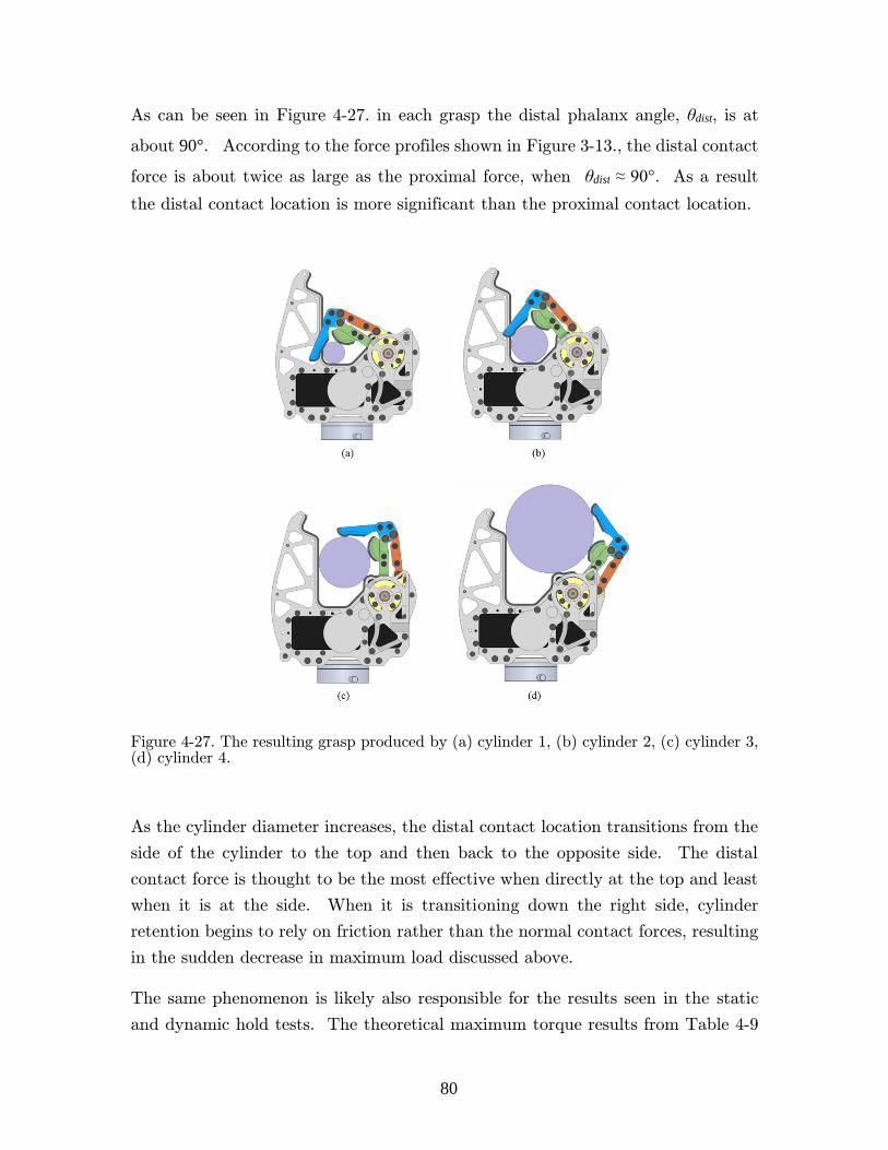
80
As can be seen in Figure 4-27. in each grasp the distal phalanx angle, θdist, is at
about 90°. According to the force profiles shown in Figure 3-13., the distal contact
force is about twice as large as the proximal force, when θdist ≈ 90°. As a result
the distal contact location is more significant than the proximal contact location.
Figure 4-27. The resulting grasp produced by (a) cylinder 1, (b) cylinder 2, (c) cylinder 3, (d) cylinder 4.
As the cylinder diameter increases, the distal contact location transitions from the
side of the cylinder to the top and then back to the opposite side. The distal
contact force is thought to be the most effective when directly at the top and least
when it is at the side. When it is transitioning down the right side, cylinder
retention begins to rely on friction rather than the normal contact forces, resulting
in the sudden decrease in maximum load discussed above.
The same phenomenon is likely also responsible for the results seen in the static
and dynamic hold tests. The theoretical maximum torque results from Table 4-9
81
also show a major decrease in withstood torque when cylinder retention began to
rely solely on friction. The Instron test verifies the earlier hypothesis that the
gripper was having difficulty supplying torque to the lumber because the fingers
were not able to wrap around the top of the object.
Based on the theoretical maximum load, one gripper could support between 30 and
44% of the robot’s weight if grasping a horizontal cylindrical railing directly above
the robot; a likely scenario that could be encountered if egressing the vehicle while
grabbing the roll cage is ever attempted. The gripper could also be used for support
on handrails when climbing stairs. In both scenarios, the controls team can use
the above results in their simulations to ensure the gripper can supply the necessary
forces and torques while being used for support.
82
5 Conclusion
The research focused on the design and validation of a gripper built for the
humanoid robot THOR. The primary goal was for the gripper to accomplish the
tasks associated with the DARPA Robotics Challenge and the Navy SAFFiR
project. Through multiple tests, it was found the gripper was in fact capable of
completing the necessary actions it was designed to accomplish, fulfilling its
primary goal.
5.1 Summary
The design was initiated with the selection of the gripper’s actuators. Then a high-
level 2D design was developed which appeared to produce secure grasps on all the
required work objects. Underactuation was used in the fingers to keep complexity
low while still adding dexterity to the gripper. A four-bar mechanism was selected
to do this due to its simplicity and robustness. The mechanics of the mechanism
were analyzed and the resulting model was used to select appropriate geometric
parameters that provided our desired performance. Our initial Mark I design was
improved upon to make a Mark II design which was much easier to manufacture,
cheaper, and performed better. A custom urethane glove with impregnated Kevlar
film was created for use in the SAFFiR project to keep water from damaging the
gripper.
Two tests were conducted to further characterize the MX-106R actuators which
were used in the gripper. The first test produced a relationship between the
internal commanded torque level and the output torque that was actually
produced. The second test determine how hard the actuators could be pushed in
83
multiple conditions without causing the actuator’s internal safety features from
shutting down the motor. The four following tests determined the gripper’s
limitations with regards to turning valves and door handles; actuating the trigger
of the drill; holding objects while being submitted to extreme movements; and
retaining cylindrical objects being pulled from its grasp.
5.2 Conclusions
The main conclusion of the research was that a relatively lightweight, robust, and
capable gripper could be created using off-the-shelf actuators. A layout with two
actuated fingers across from a rigid pylon can produce a simple design while still
maintaining an adequate level of performance. Also introducing rounded contact
surfaces on the fingers appeared to improve the quality of the grasp for many
objects.
There were several failures during the static and dynamic hold tests. The lumber
could only be picked up directly at its center without dislodging. Then,
furthermore, even while grasping at its center, if the gripper is quickly swung
upwards in either arm orientation B or D the lumber would again dislodge. Using
the Instron, it was verified that the failures were due to the retention of the lumber
relying mostly on frictional forces to counteract the moments applied to the lumber.
During the trigger test it was also found trigger compression could be improved
greatly by using a thinner distal phalanx without rubber contact pads.
5.3 Recommendation for Further Work
Since the gripper was thoroughly tested some areas of improvement that would
lead to overall better gripper performance were able to be determined.
Our recommendation for mitigating the issue of grip loss when picking up lumber
is to extend the lengths of the fingers. Doing so will allow the fingers to wrap
further around objects hopefully leading to normal forces supplying most of the
counteractive torque to the objects as opposed to weaker friction forces taking the
brunt.

84
The other area for improvement was the small size of the position window that
resulted in full trigger compression. Unfortunately this is a difficult area to improve
due to the limited control that comes with underactuated fingers. A detailed
analysis of the evolution of the contact forces as the trigger compresses is probably
needed to fully understand the issue, but once completed the finger mechanism
could be further optimized to supply a more robust trigger pull. Other simpler
improvements would be decreasing the friction produced by the distal phalanx and
decreasing the overall width of the gripper so the trigger can be contacted further
down its length.
Even though the MX-106R actuators were easy to design with since they internally
contained multiple required subsystems, they only allowed for a very limited
number of possible layout schemes due to their bulky design. Instead, developing
a design using a DC motor with a custom transmission and custom motor controller
could provide more design freedom and as a result could potentially lead to an
overall more effective gripper.
The rounded contact surfaces on the fingers could provide more secure grasps due
to more effective contact locations and to an interesting wedging effect. Future
work could contain the modeling and analysis of the potential benefits that come
from adding rounded contact surfaces to the phalanxes.
Due to fixed gear ratios between the actuators and fingers, typically a designer has
to make a tradeoff between the amount of torque supplied to the finger and the
speed of said finger. Future work could also contain the development and
introduction of a simple mechanism that would automatically change the gear ratio
of the transmission when contact with an object is made.
85
Bibliography
[1] B. Lee, V. Orekhov, D. Lahr, and D. Hong, “Design and measurement error
analysis of a low-friction, lightweight linear series elastic actuator,” Proceedings of the ASME International Design Engineering Technical Conferences & computers and Information Engineering Conference, 2013.
[2] C. Knabe, B. Lee, V. Orekhov, and D. Hong, “Design of a compact,
lightweight, electromechanical linear series elastic actuator,” Proceedings of the ASME International Design Engineering Technical Conferences & computers and Information Engineering Conference, 2014.
[3] M. Rouleau and D. Hong, “Design of an underactuated robotic end-effector
with a focus on power tool manipulation,” Proceedings of the ASME International Design Engineering Technical Conferences & computers and Information Engineering Conference, 2014.
[4] B. Lee, C. Knabe, V. Orekhov, and D. Hong, “Design of a human-like range
of motion hip joint for humanoid robots,” Proceedings of the ASME International Design Engineering Technical Conferences & computers and Information Engineering Conference, 2014.
[5] C. Knabe, B. Lee, and D. Hong, “An inverted straight line mechanism for
augmenting joint range of motion in a humanoid robot,” Proceedings of the ASME International Design Engineering Technical Conferences & computers and Information Engineering Conference, 2014.
[6] L. Birglen, C. Gosselin, and T. Laliberté, Underactuated robotic hands. 2008.
[7] R. C. Goertz, “Fundamentals of general purpose remote manipulators,”
Nucleonics, vol. 10, no. 11, pp. 36–42, 1952.
[8] R. Mosher, “Force reflection electrohydraulic servo manipulator,” Electro-Technology, 1960.

86
[9] T. Okada, “Object-handling system for manual industry,” Systems, Man and Cybernetics, IEEE Transactions …, no. 2, pp. 79–89, 1979.
[10] J. Salisbury and J. Craig, “Articulated hands force control and kinematic
issues,” The International Journal of Robotics, vol. 1, no. 1, pp. 4–17, 1982.
[11] S. Jacobsen and E. Iversen, “Design of the Utah/MIT dextrous hand,” Proceeding of the IEEE International Conference on Robotics and Automation, 1986.
[12] J. Butterfaß and M. Grebenstein, “DLR-Hand II: Next generation of a
dextrous robot hand,” Proceeding of the IEEE International Conference on Robotics and Automation, pp. 109–114, 2001.
[13] M. Reichel, “Transformation of shadow dextrous hand and shadow finger test unit from prototype to product for intelligent manipulation and
grasping,” Intelligent Manipulation and Grasping, Inter Conference, 2004.
[14] M. Quigley, C. Salisbury, a. Y. Ng, and J. K. Salisbury, “Mechatronic
design of an integrated robotic hand,” The International Journal of Robotics Research, vol. 33, no. 5, pp. 706–720, Feb. 2014.
[15] A. Bicchi and V. Kumar, “Robotic grasping and contact: A review,” Proceeding of the IEEE International Conference on Robotics and Automation, 2000.
[16] C. M. Gosselin, “Adaptive Robotic Mechanical Systems: A Design
Paradigm,” Journal of Mechanical Design, vol. 128, no. 1, p. 192, 2006.
[17] E. Spellerberg, “US Patent 42,515.”
[18] S. Hirose and Y. Umetani, “The development of soft gripper for the
versatile robot hand,” Mechanism and Machine Theory, vol. 13, no. 1, pp.
351–359, 1978.
[19] M. Kaneko and M. Higashimori, “The 100 G capturing robot-too fast to
see,” IEEE/ASME Transactions on mechatronics, vol. 8, no. 1, pp. 37–44, 2003.
[20] a. M. Dollar and R. D. Howe, “The Highly Adaptive SDM Hand: Design
and Performance Evaluation,” The International Journal of Robotics Research, vol. 29, no. 5, pp. 585–597, Feb. 2010.
[21] L. U. Odhner, L. P. Jentoft, M. R. Claffee, N. Corson, Y. Tenzer, R. R.
Ma, M. Buehler, R. Kohout, R. D. Howe, and a. M. Dollar, “A compliant,
87
underactuated hand for robust manipulation,” The International Journal of Robotics Research, vol. 33, no. 5, pp. 736–752, Feb. 2014.
[22] “Four Tracks of the DRC Infographic,” www.theroboticschallenge.org2, 2013.
[23] P. Hebert, M. Bajracharya, J. Ma, and N. Hudson, “Mobile manipulation
and mobility as manipulation: design and algorithms of RoboSimian,” 2014.
[24] G. Schulz, “End effector with load-sensitive digit actuation mechanisms,” US Patent 5,280,981, 1994.
[25] T. Moyer, E. Faulring, and J. Santos-Munne, “One motor finger
mechanism,” US Patent 8,470,051, 2013.
[26] E. Johnson, T. Van Doren, T. Lontz, and B. Coleman, “Modular
Rotational Electric Actuator,” European Patent 2,532,927, 2014.
[27] G. A. Kragten, “Underactuated hands; fundamentals, performance analysis
and design,” Technische Universiteit Delft, 2011.
[28] T. Laliberté and C. Gosselin, “Simulation and design of underactuated
mechanical hands,” Mechanism and Machine Theory, vol. 33, no. I, pp. 39–57, 1998.
[29] L. Birglen and C. Gosselin, “Grasp-state plane analysis of two-phalanx
underactuated fingers,” Mechanism and Machine Theory, no. November 2005, 2006.
[30] L. Birglen and C. Gosselin, “Kinetostatic analysis of underactuated fingers,”
IEEE Transactions on Robotics and Automation, vol. 20, no. 2, pp. 211–221, 2004.
[31] S. Montambault and C. M. Gosselin, “Analysis of underactuated
mechanical grippers,” Journal of Mechanical Design, vol. 123, no. 3, p. 367, 2001.
[32] L. Birglen and C. Gosselin, “Underactuation in robotic grasping hands,”
vol. 4, no. 3, pp. 1–11, 2003.
[33] L. Birglen and C. M. Gosselin, “On the force capability of underactuated
fingers,” 2003 IEEE International Conference on Robotics and Automation (Cat. No.03CH37422), vol. 1, pp. 1139–1145, 2003.
[34] C. M. Gosselin and T. Laliberte, “Underactuated mechanical finger with
return actuation,” US Patent 5,762,390, 1998.
88
[35] T. Laliberte and C. Gosselin, “Actuation systems for highly underactuated
gripping mechanism,” US Patent 6,505,870, 2003.
[36] E. Martin, A. Desbiens, T. Laliberte, and C. Gosselin, “SARAH hand used
for space operation on STVF robot,” Proceeding of the International Conference on Intelligent Manipulation and Grasping, 2004.
[37] L. A. Demers, S. Lefrancois, and J.-P. Jobin, “Gripper having a two degree of freedom underactuated mechanical finger for encompassing and pinch
grasping,” US Patent 8,973,958, 2012.
[38] “Robotiq-3-Finger-Adaptive-Gripper-Specifications1.pdf,” www.robotiq.com.
[39] S. Krut, “A force-isotropic underactuated finger,” Proceeding of the IEEE International Conference on Robotics and Automation, no. April, 2005.
[40] W. Townsend, “The BarrettHand grasper-programmably flexible part
handling and assembly,” Industrial Robot: an Iternational Journal, vol. 27,
no. 3, pp. 181–188, 2000.
[41] D. M. Aukes, B. Heyneman, J. Ulmen, H. Stuart, M. R. Cutkosky, S. Kim,
P. Garcia, and a. Edsinger, “Design and testing of a selectively compliant
underactuated hand,” The International Journal of Robotics Research, vol.
33, no. 5, pp. 721–735, Feb. 2014.
[42] O. Pfaff, S. Simeonov, and I. Cirovic, “Application of finray approach for
production processs automation,” Proceedings of the International DAAAM Symposium, vol. 22, no. 1, pp. 1247–1248, 2011.
[43] “Daily high/low temperature records by month and day, Los Angeles Civic
Center,” http://www.laalmanac.com/weather/we04.htm.
[44] “Rules of the DRC Finals,” www.theroboticschallenge.org, 2014.

89
Appendix A: Auxiliary Results
A.1 F/T Data from Turning Test
Figure A-1. The F/T sensor data for the door handle trial.
0 2 4 6 8 10 12 14 16 18-200
-150
-100
-50
0
50
100
150
200
Time [sec]
Pull
Forc
e [
N]
0 2 4 6 8 10 12 14 16 18-20
-15
-10
-5
0
5
10
15
20
Torq
ue [
Nm
]

90
Figure A-2. The F/T sensor data for the axial large hand wheel trial.
Figure A-3. The F/T sensor data for the radial large hand wheel trial.
0 5 10 15 20 25 30 35 40 45 50-200
-150
-100
-50
0
50
100
150
200
Time [sec]
Pull
Forc
e [
N]
0 5 10 15 20 25 30 35 40 45 50-20
-15
-10
-5
0
5
10
15
20
Torq
ue [
Nm
]
0 20 40 60 80 100 120 140-200
-150
-100
-50
0
50
100
150
200
Time [sec]
Pull
Forc
e [
N]
0 20 40 60 80 100 120 140-20
-15
-10
-5
0
5
10
15
20
Torq
ue [
Nm
]
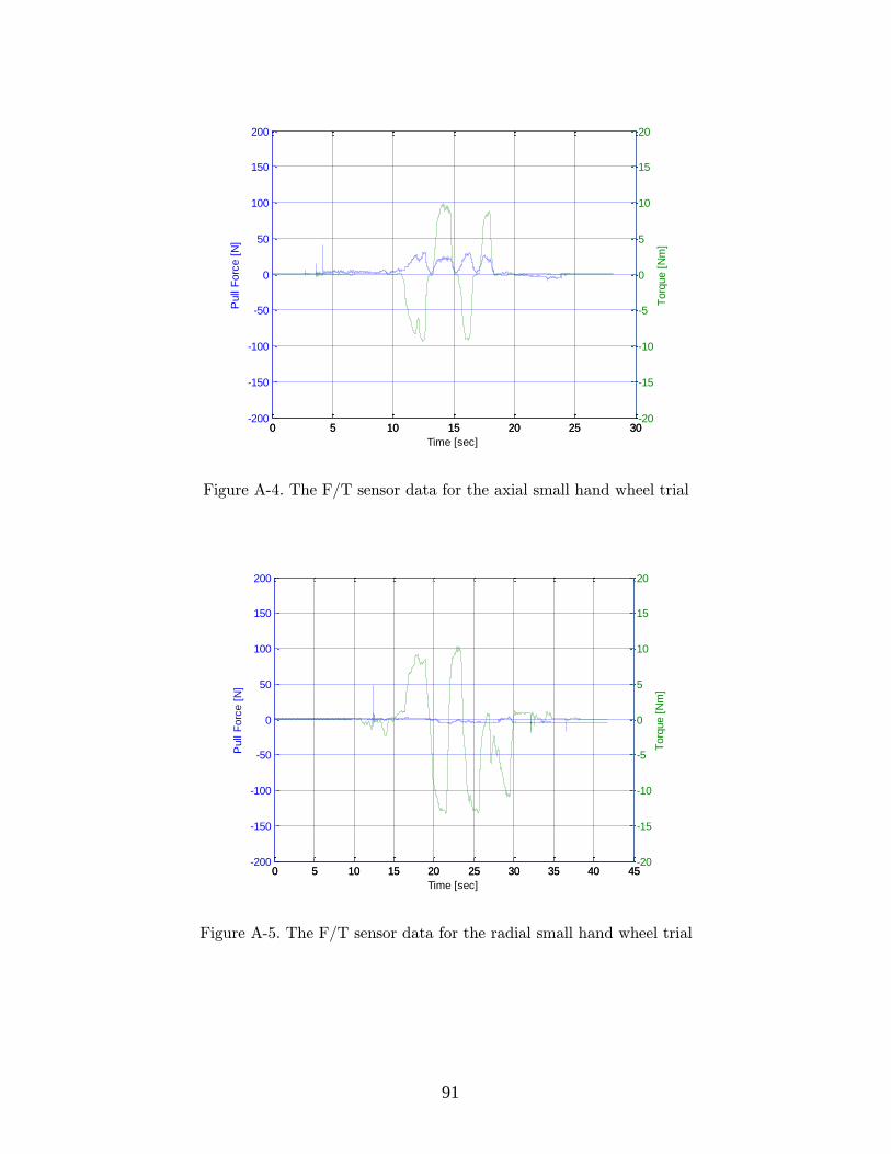
91
Figure A-4. The F/T sensor data for the axial small hand wheel trial
Figure A-5. The F/T sensor data for the radial small hand wheel trial
0 5 10 15 20 25 30-200
-150
-100
-50
0
50
100
150
200
Time [sec]
Pull
Forc
e [
N]
0 5 10 15 20 25 30-20
-15
-10
-5
0
5
10
15
20
Torq
ue [
Nm
]
0 5 10 15 20 25 30 35 40 45-200
-150
-100
-50
0
50
100
150
200
Time [sec]
Pull
Forc
e [
N]
0 5 10 15 20 25 30 35 40 45-20
-15
-10
-5
0
5
10
15
20
Torq
ue [
Nm
]

92
Figure A-6. The F/T sensor data for lever valve trial.
0 5 10 15 20 25 30 35-200
-150
-100
-50
0
50
100
150
200
Time [sec]
Pull
Forc
e [
N]
0 5 10 15 20 25 30 35-20
-15
-10
-5
0
5
10
15
20
Torq
ue [
Nm
]