Embed Size (px)
Citation preview
Paradigms for Graph Drawing
Graph Drawing: Algorithms for the Visualization of Graphs - Chapter 2
Presented by Liana Diesendruck
Graph Drawing Methods: Parameters
Input: graph G – E(G) and V(G) Additional input: class of G - like: planar,
directed acyclic, tree, etc. Specific algorithms work better for specific type of
graphs Highlight a particular graph characteristic
Graph Drawing Methods: Concepts
Drawing convention – אמנה (basic rule that the drawing must satisfy to be admissible)
Aesthetics - אסתטיקה Constraints - אילוצים
Graph Drawing Methods: Concepts
Drawing conventions: Polyline drawing Straight-line drawing Orthogonal drawing Grid drawing Planar drawing Upward drawing
Graph Drawing Methods: Concepts
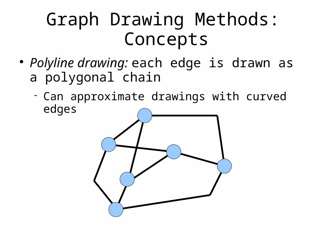
Polyline drawing: each edge is drawn as a polygonal chain Can approximate drawings with curved edges
Graph Drawing Methods: Concepts
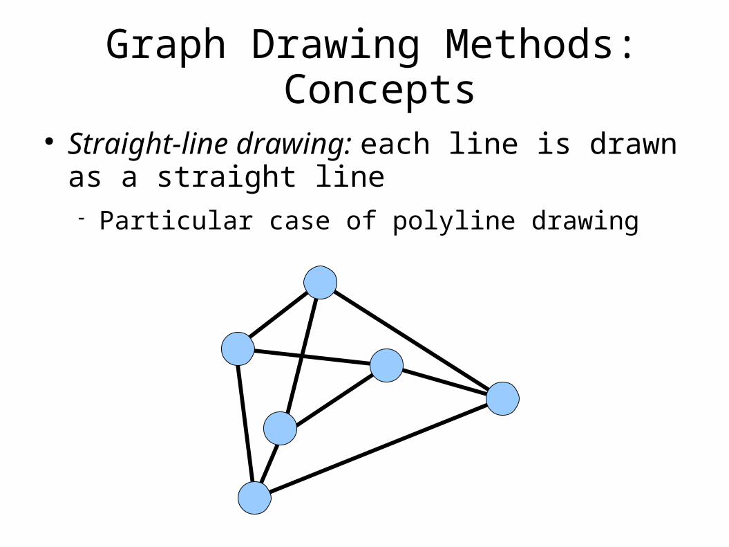
Straight-line drawing: each line is drawn as a straight line Particular case of polyline drawing
Graph Drawing Methods: Concepts
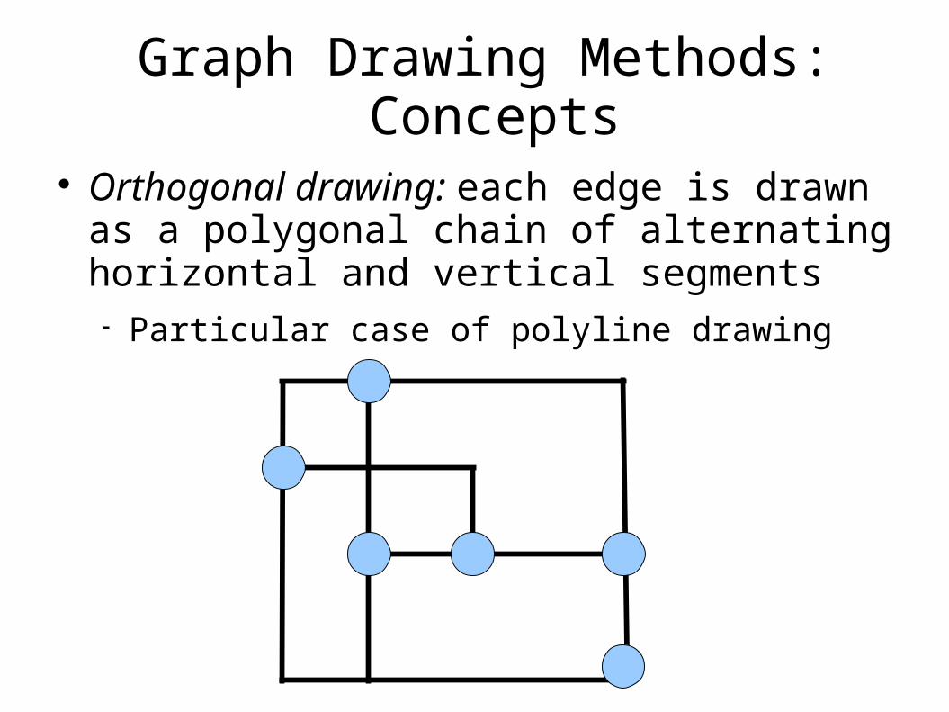
Orthogonal drawing: each edge is drawn as a polygonal chain of alternating horizontal and vertical segments Particular case of polyline drawing
Graph Drawing Methods: Concepts
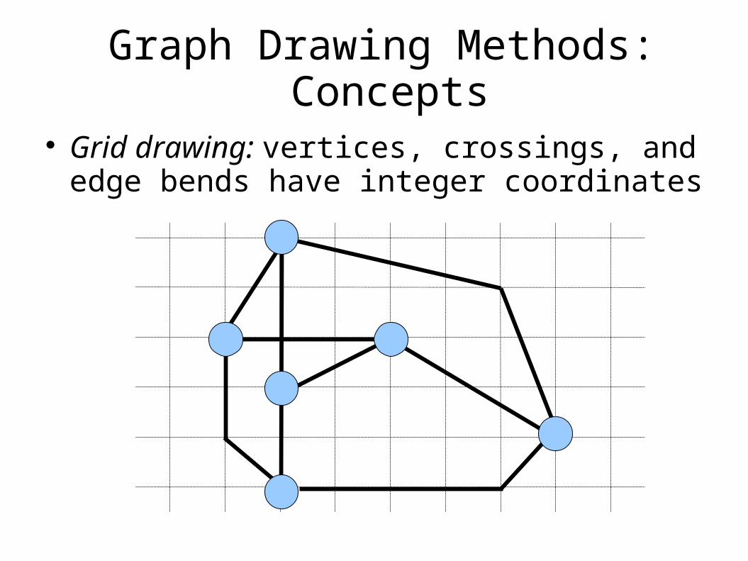
Grid drawing: vertices, crossings, and edge bends have integer coordinates
Graph Drawing Methods: Concepts
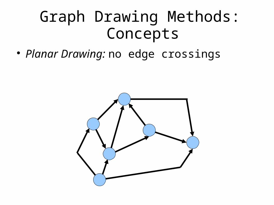
Planar Drawing: no edge crossings
Graph Drawing Methods: Concepts
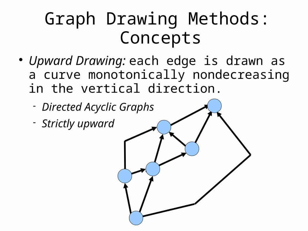
Upward Drawing: each edge is drawn as a curve monotonically nondecreasing in the vertical direction. Directed Acyclic Graphs Strictly upward
Graph Drawing Methods: Concepts
Aesthetics: specify graphic properties we would want to apply as much as possible to achieve readability. Crossings Area Total / Maximum / Uniform Edge Length Total / Maximum / Uniform Bends Angular resolution Aspect Ratio Symmetry
Graph Drawing Methods: Concepts
Crossings: minimization of the total number of crossings. Ideally we would have planar graphs (not always
possible).
Graph Drawing Methods: Concepts
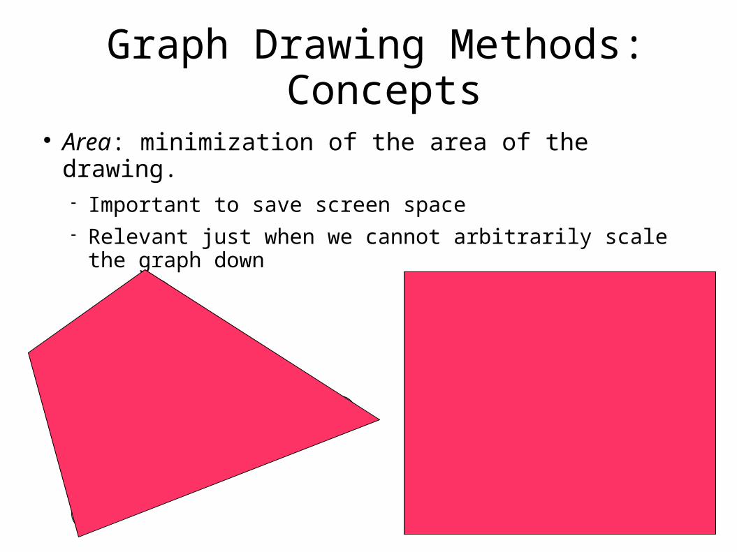
Area: minimization of the area of the drawing. Important to save screen space Relevant just when we cannot arbitrarily scale the
graph down
Graph Drawing Methods: Concepts
Total Edge Length: minimization of the sum of the lengths of the edges.
Maximum Edge Length: minimization of the maximum length of an edge. Both relevant just when we cannot arbitrarily scale
the graph down. Uniform Edge Length: minimization of the
variance of the lengths of the edges.
Graph Drawing Methods: Concepts
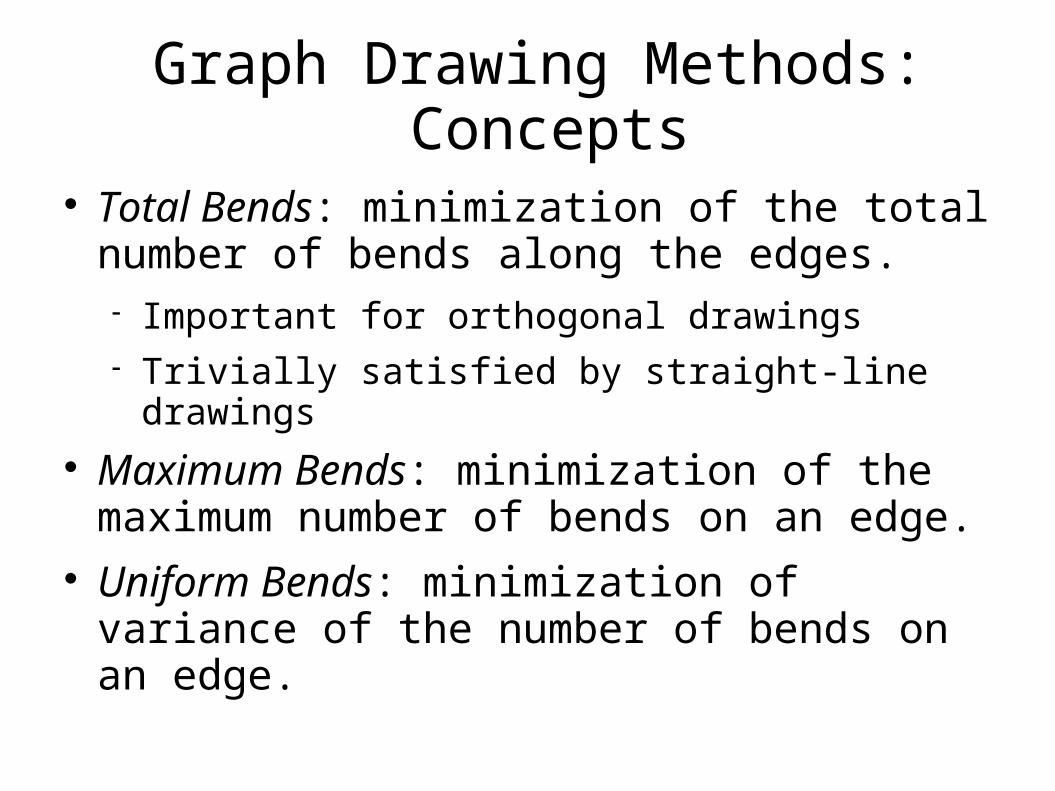
Total Bends: minimization of the total number of bends along the edges. Important for orthogonal drawings Trivially satisfied by straight-line drawings
Maximum Bends: minimization of the maximum number of bends on an edge.
Uniform Bends: minimization of variance of the number of bends on an edge.
Graph Drawing Methods: Concepts
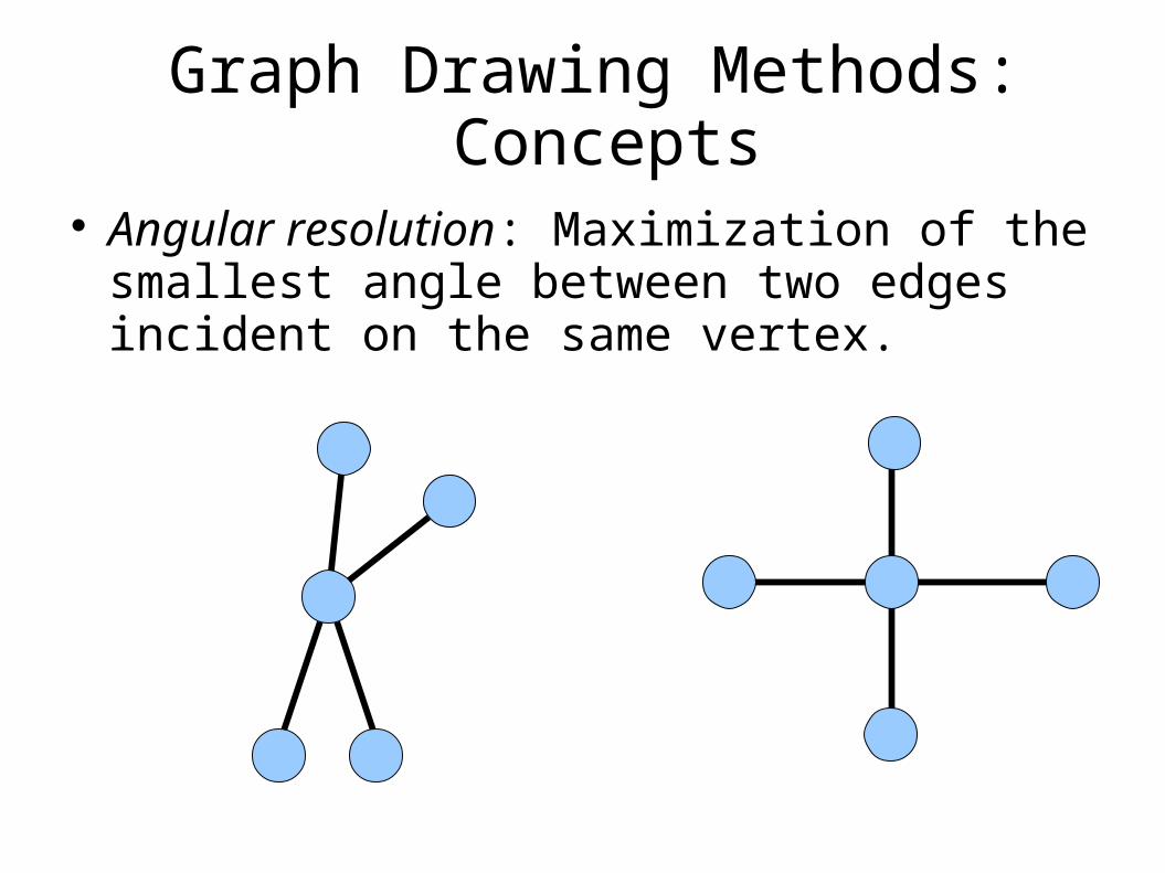
Angular resolution: Maximization of the smallest angle between two edges incident on the same vertex.
Graph Drawing Methods: Concepts
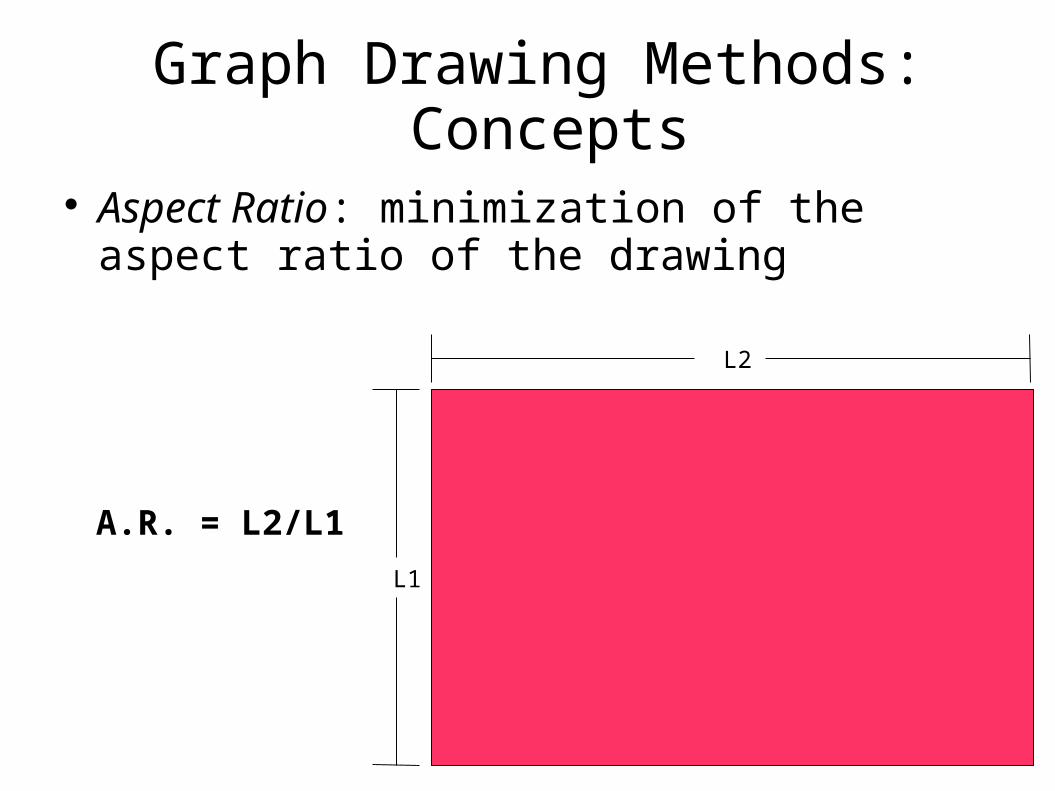
Aspect Ratio: minimization of the aspect ratio of the drawing
L2
L1
A.R. = L2/L1
Graph Drawing Methods: Concepts
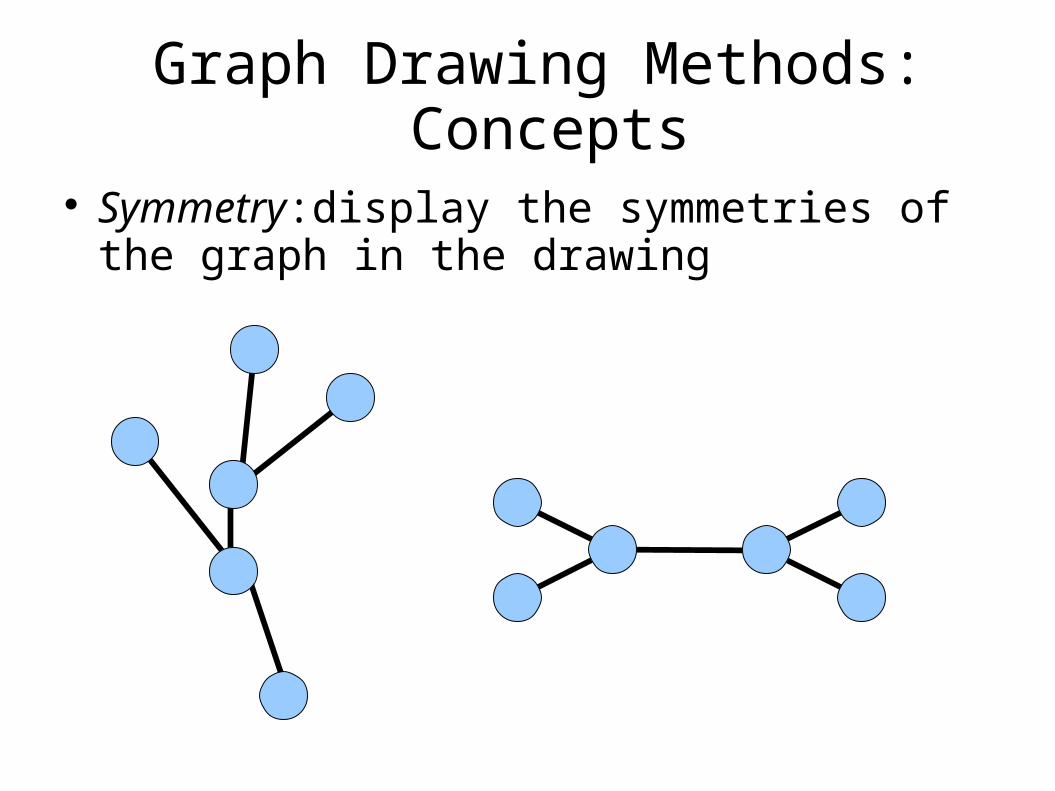
Symmetry:display the symmetries of the graph in the drawing
Graph Drawing Methods: Concepts
Most aesthetics are associated with optimization problems – most of them computationally hard.
Approximation strategies and heuristics for real-time response.
Constraints: refer to specific subgraphs and subdrawings. Commonly used in visualization applications. Usually include: Center: place a given vertex close to the center of
the drawing External: place a given vertex on the outer
boundary of the drawing Cluster: place a subset of vertices close together Left-right sequence: draw a given path horizontally
aligned from the left to the right Shape: draw a given subgraph with a predefined
“shape”
Graph Drawing Methods: Concepts
Precedence Among Aesthetics
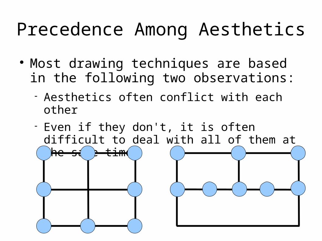
Most drawing techniques are based in the following two observations: Aesthetics often conflict with each other Even if they don't, it is often difficult to deal with all
of them at the same time
Precedence Among Aesthetics
Graph drawing methodologies established a precedence among aesthetics.
Such precedence is more suitable for certain applications than for others.
The common approaches to graph drawings usually divide the process into a sequence of steps.
Each step is targeted to satisfy a certain subclass of aesthetics.
Topology-Shape-Metrics Approach
Suited for orthogonal grid drawings Topology: two orthogonal drawings have the
same topology if one can be obtained from the other by deformation that doesn't alter the sequence of edges contouring the faces of the drawing
Topology-Shape-Metrics Approach
Shape: two orthogonal drawings have the same shape if one can be obtained from the other by modifying the lengths of the segments of the edges without changing their angles
Metrics: two orthogonal drawings have the same metrics if they are congruent, up to a translation and/or rotation
Topology-Shape-Metrics Approach
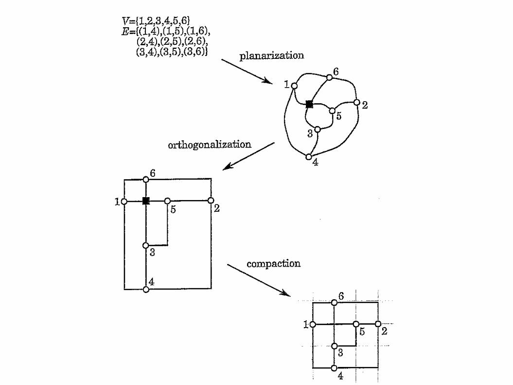
The approach has 3 steps: Planarization Orthogonalization Compaction
Topology-Shape-Metrics Approach
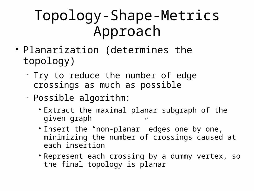
Planarization (determines the topology) Try to reduce the number of edge crossings as
much as possible Possible algorithm:
Extract the maximal planar subgraph of the given graph Insert the “non-planar” edges one by one, minimizing the
number of crossings caused at each insertion Represent each crossing by a dummy vertex, so the final
topology is planar
Topology-Shape-Metrics Approach
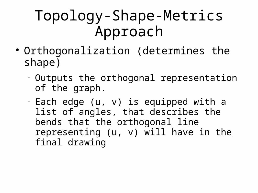
Orthogonalization (determines the shape) Outputs the orthogonal representation of the graph. Each edge (u, v) is equipped with a list of angles,
that describes the bends that the orthogonal line representing (u, v) will have in the final drawing
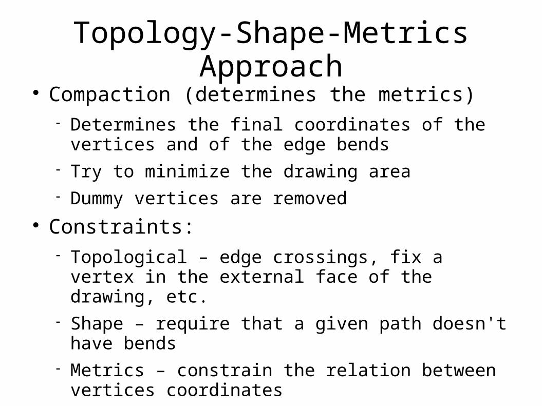
Topology-Shape-Metrics Approach Compaction (determines the metrics)
Determines the final coordinates of the vertices and of the edge bends
Try to minimize the drawing area Dummy vertices are removed
Constraints: Topological – edge crossings, fix a vertex in the
external face of the drawing, etc. Shape – require that a given path doesn't have
bends Metrics – constrain the relation between vertices
coordinates
Hierarchical Approach
Suited for directed graphs, particularly for acyclic directed graphs with the polyline downward drawing convention.
Steps: Layer assignment Crossing reduction X-coordinate assignment
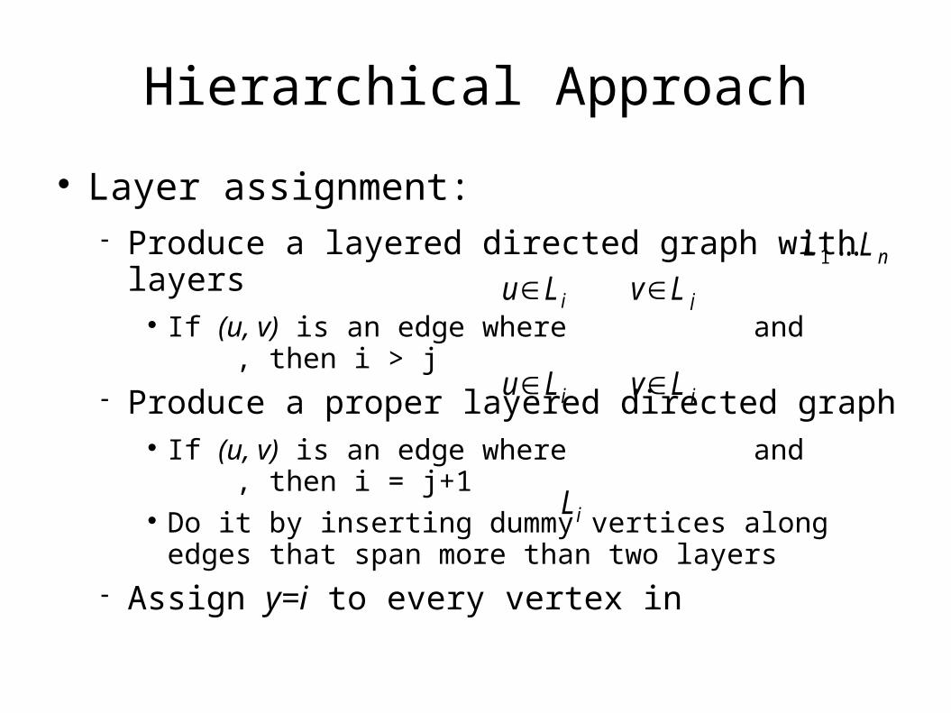
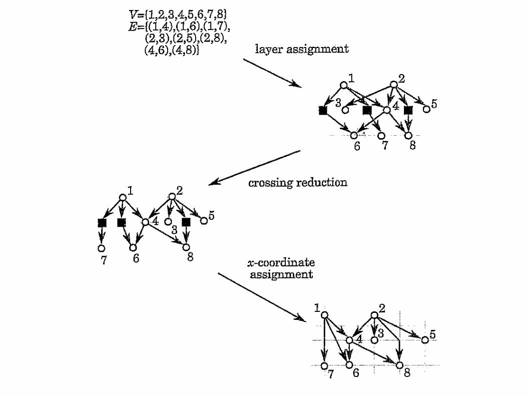
Hierarchical Approach
Layer assignment: Produce a layered directed graph with layers
If (u, v) is an edge where and , then i > j Produce a proper layered directed graph
If (u, v) is an edge where and , then i = j+1 Do it by inserting dummy vertices along edges that span
more than two layers Assign y=i to every vertex in
u∈Li v∈L j
L1 ...L n
Li
u∈Li v∈L j
Hierarchical Approach
Crossing reduction: Receive the proper layered graph Order the vertices on each layer, so to minimize the
amount of edge crossings X-coordinate assignment:
Preserve the order received on each layer Assign x-coordinates to every vertex Represent each edge by a straight line Remove dummy vertices
Hierarchical Approach
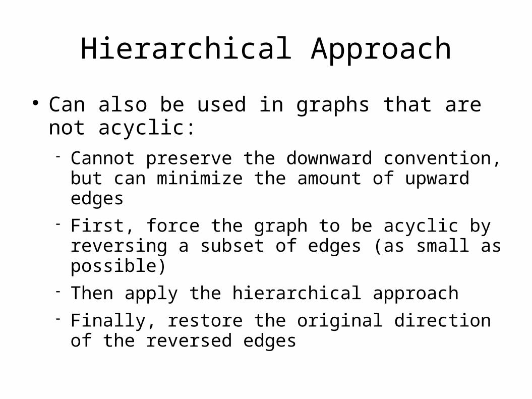
Can also be used in graphs that are not acyclic: Cannot preserve the downward convention, but can
minimize the amount of upward edges First, force the graph to be acyclic by reversing a
subset of edges (as small as possible) Then apply the hierarchical approach Finally, restore the original direction of the reversed
edges
Visibility Approach
Suited for drawing graphs with the polyline drawing convention
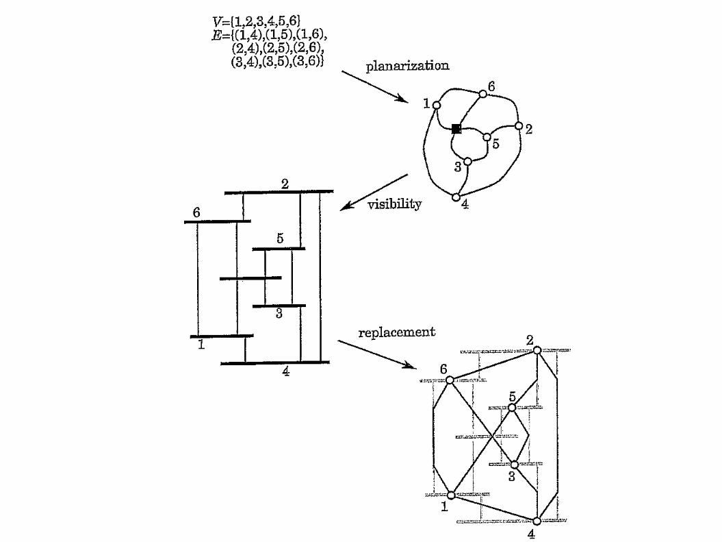
Steps: Planarization (as in the topology-shape-metrics
approach) Visibility Replacement
Visibility Approach
Visibility: Construct a visibility representation of the graph:
Map each vertex to a horizontal segment Map each edge to a vertical segment s.t., the vertical segment (u,v) has endpoints on the
horizontal segments representing u and v and does not intersect with any other horizontal segment
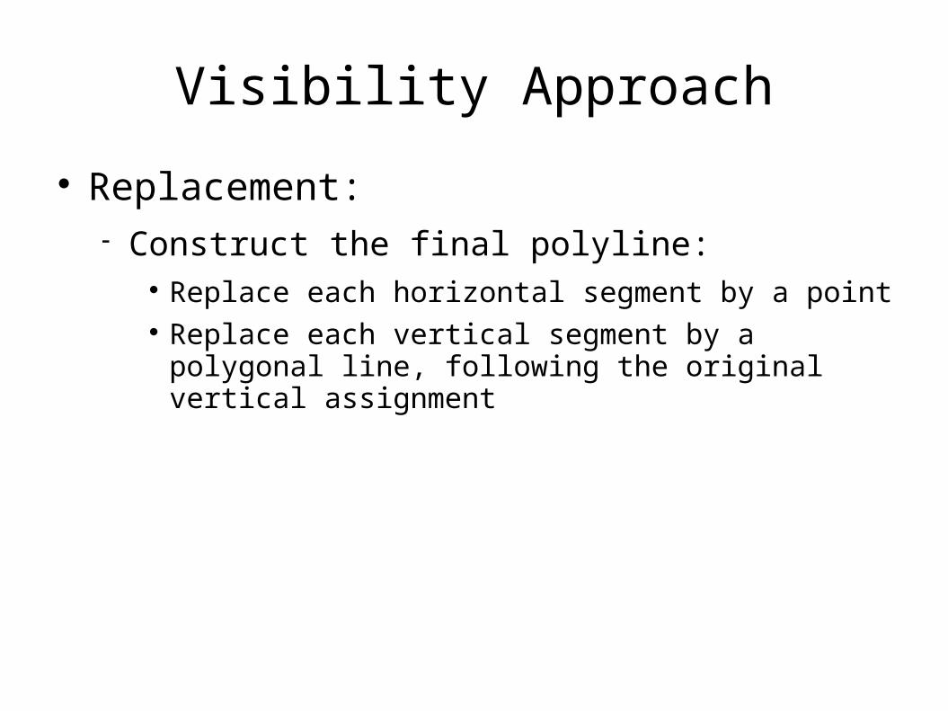
Visibility Approach
Replacement: Construct the final polyline:
Replace each horizontal segment by a point Replace each vertical segment by a polygonal line,
following the original vertical assignment
Visibility Approach
Planarization step as in the topology-shape-metrics approach
Visibility step similar to layer assignment in the hierarchical approach
So, it can be considered as a meeting point of the topology-shape-metrics and the hierarchical approaches
Aesthetic considerations and general constraints can be added to suitable steps
Augmentation Approach
Also suited for the polyline drawing convention Basic idea: add edges and/or vertices to the
graph to obtain a new graph with a stronger structure and better drawability properties
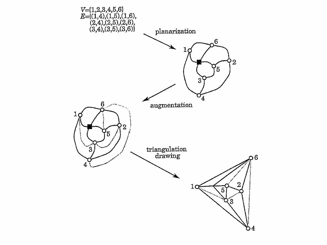
Steps: Planarization (as in the topology-shape-metrics
approach) Augmentation Triangulation drawing
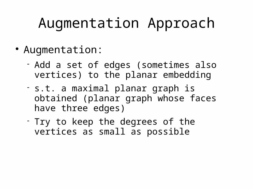
Augmentation Approach
Augmentation: Add a set of edges (sometimes also vertices) to the
planar embedding s.t. a maximal planar graph is obtained (planar
graph whose faces have three edges) Try to keep the degrees of the vertices as small as
possible
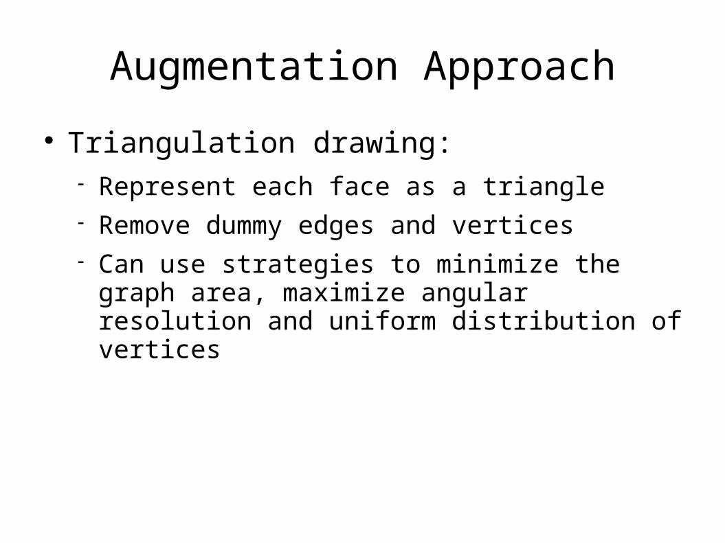
Augmentation Approach
Triangulation drawing: Represent each face as a triangle Remove dummy edges and vertices Can use strategies to minimize the graph area,
maximize angular resolution and uniform distribution of vertices
Augmentation Approach
If the graph is planar, then the result drawing is straight-line. Otherwise, the dummy vertices become bends.
This approach is less suitable than others for supporting constraints.
Force-directed Approach
Good for creating straight-line drawings of undirected graphs
Popular mostly because it is easy to understand and code
Simulates a system of forces over the input graph and outputs a locally minimum energy configuration
Two ingredients: Force model Locally minimum configuration finding technique
Force-directed Approach Example of a force model:
Each pair (u,v) is assigned with a spring with length luv that is the number of edges on the shortest path between u and v. The spring follows Hooke's law.
Locally minimum configuration finding technique: Usually by numerical analysis (simple iterative
methods) Tends to give highly symmetric drawings and
distribute vertices evenly Constrains can be added by special forces
Divide and Conquer Approach
Suited for graphs that can be easily decomposed into subgraphs, such as trees.
Main idea: split the graph into subgraphs; recursively draw the subgraphs; the drawing of the whole graph is obtained by
gluing the drawings of the subgraphs.
Divide and Conquer Approach
Example: algorithm for drawing binary trees in 2 main steps: Layer assignment (as in the hierarchical approach),
trying to minimize the distance from the root Divide and Conquer:
If the tree is a single vertex, then trivially construct its drawing on the assigned layer. If the tree is empty, do nothing.
Else, (divide) recursively divide the left and right subtrees and (conquer) place the two subdrawings obtained close to one another with the root positioned halfway between the roots of the subtrees.
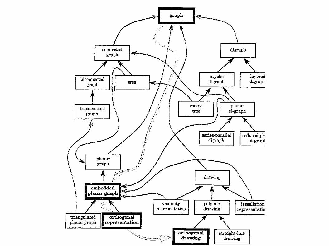
General Framework for Graph Drawing
Let C be a class of graphs and let C' be a subclass of C. If an algorithm can be applied tp the graphs of C, it can also be applied to the graphs of C'. That is, C' inherits the algorithms for C.
Graph drawing methodology is composed of a series of relatively independent functional steps. Where the inputs and outputs are always graphs.
General Framework for Graph Drawing
Inheritance hierarchy of classes of graphs Set of methods with the following
characteristics: Each method is associated with a class of graphs
and maps a graph of that class into a graph of another class
A method associated with a class of graphs C is also associated with all the descendant classes of C in the hierarchy.
General Framework for Graph Drawing
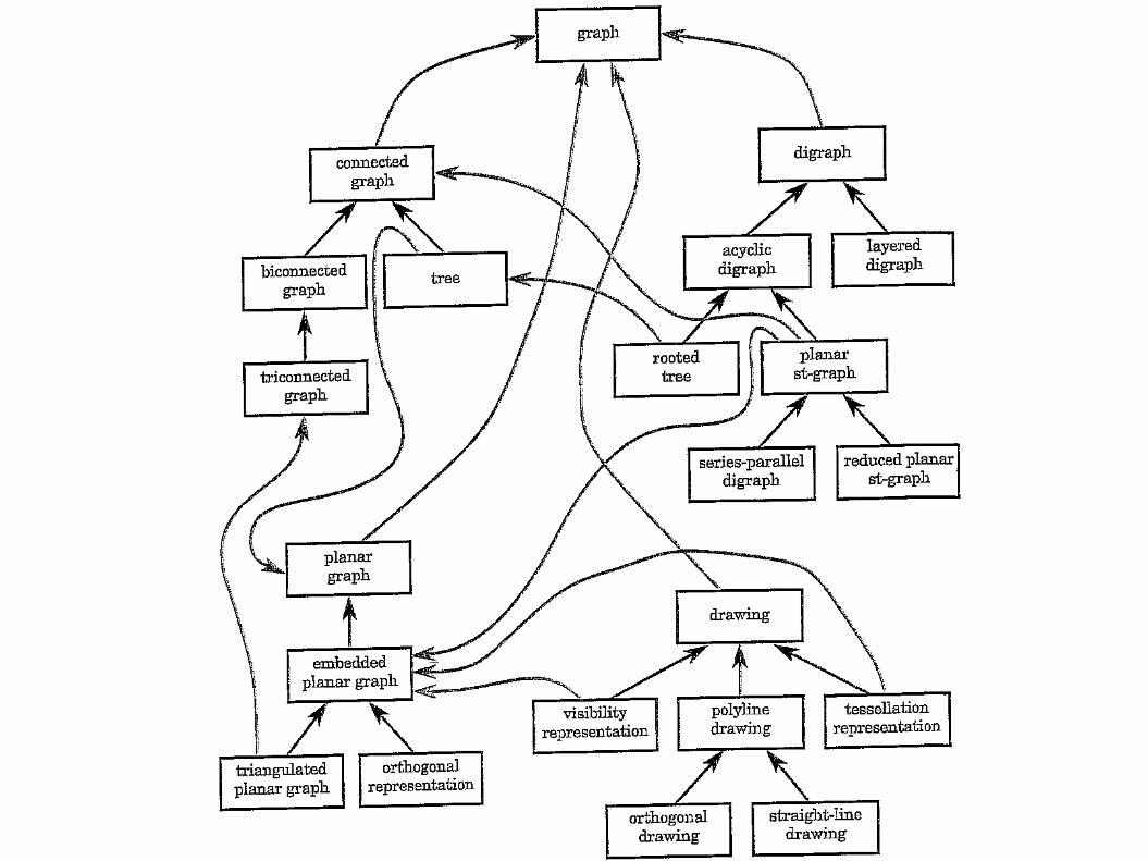
The most general class in the hierarchy is Graph
According to certain properties, the subclasses of Graph are: Connected Graphs Planar Graphs Directed Graphs Drawing
Summary
Drawing conventions Aesthetics Constraints Precedence among aesthetics 6 different approaches to graph drawing Hierarchy and inheritance