Embed Size (px)
Citation preview
INV ITEDP A P E R
The State of the Art of Electric,Hybrid, and Fuel Cell VehiclesWith their superior fuel economy and performance, hybrid vehicles will likely
increase in popularity in coming years; further development of control
theory for hybrids is essential for their progress.
By C. C. Chan, Fellow IEEE
ABSTRACT | With the more stringent regulations on emissions
and fuel economy, global warming, and constraints on energy
resources, the electric, hybrid, and fuel cell vehicles have
attracted more and more attention by automakers, govern-
ments, and customers. Research and development efforts have
been focused on developing novel concepts, low-cost systems,
and reliable hybrid electric powertrain. This paper reviews
the state of the art of electric, hybrid, and fuel cell vehicles. The
topologies for each category and the enabling technologies are
discussed.
KEYWORDS | Electric drives; electric machines; electric vehicle;
fuel cell vehicles; hybrid electric vehicle (HEV); modeling;
power electronics
I . INTRODUCTION
Compared to conventional vehicles, hybrid electric vehi-cles (HEVs) are more fuel efficient due to the optimization
of the engine operation and recovery of kinetic energy
during braking. With the plug-in option (PHEV), the
vehicle can be operated on electric-only modes for a driving
range of up to 30–60 km. The PHEVs are charged overnight
from the electric power grid where energy can be generated
from renewable sources such as wind and solar energy
and from nuclear energy. Fuel cell vehicles (FCV) usehydrogen as fuel to produce electricity, therefore they are
basically emission free. When connected to electric power
grid (V2G), the FCV can provide electricity for emergency
power backup during a power outage. Due to hydrogen
production, storage, and the technical limitations of fuel
cells at the present time, FCVs are not available to the
general public yet. HEVs are likely to dominate theadvanced propulsion in coming years. Hybrid technologies
can be used for almost all kinds of fuels and engines.
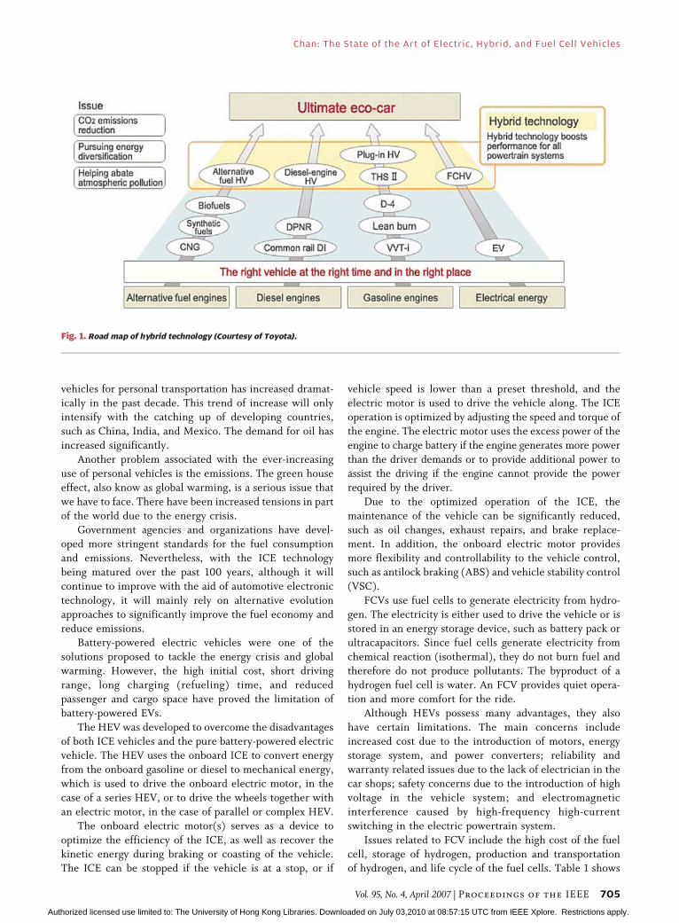
Therefore, it is not a transition technology. Fig. 1 shows
the road map of hybrid technologies.
In HEVs and FCVs, there are more electrical com-
ponents used, such as electric machines, power electronic
converters, batteries, ultracapacitors, sensors, and micro-
controllers. In addition to these electrification componentsor subsystems, conventional internal combustion engines
(ICE), and mechanical and hydraulic systems may still be
present. The challenge presented by these advanced
propulsion systems include advanced powertrain compo-
nents design, such as power electronic converters, electric
machines and energy storage; power management; mod-
eling and simulation of the powertrain system; hybrid
control theory and optimization of vehicle control.This paper provides an overview of the state of the art
of electric vehicles (EVs), HEVs and FCVs, with a focus on
HEVs. Section II tries to answer a fundamental question:
why EV, HEV, and FCV? It also looks at the key issues of
HEVs and FCVs. Section III reviews the history of EVs,
HEVs, and FCVs. Section IV highlights the engineering
philosophy of EVs, HEVs, and FCVs. Section V presents
the architectures of HEVs and FCVs. Section VI providesan overview of the current status of HEVs and FCVs.
Section VII discusses the key technologies, including elec-
tric motor technology, power converter technology, control
and power management technology, and energy storage
devices. Finally, conclusions are given in Section VIII.
II . WHY EVs, HEVs, AND FCVs?
Vehicles equipped with conventional internal combustion
engines (ICE) have been in existence for over 100 years.
With the increase of the world population, the demand for
Manuscript received August 8, 2006; revised December 28, 2006.
The author is with the International Research Centre for Electric Vehicles, University of
Hong Kong, Hong Kong, and the Harbin Institute of Technology, Wuhan University,
China (e-mail: [email protected]).
Digital Object Identifier: 10.1109/JPROC.2007.892489
704 Proceedings of the IEEE | Vol. 95, No. 4, April 2007 0018-9219/$25.00 �2007 IEEE
Authorized licensed use limited to: The University of Hong Kong Libraries. Downloaded on July 03,2010 at 08:57:15 UTC from IEEE Xplore. Restrictions apply.
vehicles for personal transportation has increased dramat-
ically in the past decade. This trend of increase will onlyintensify with the catching up of developing countries,
such as China, India, and Mexico. The demand for oil has
increased significantly.
Another problem associated with the ever-increasing
use of personal vehicles is the emissions. The green house
effect, also know as global warming, is a serious issue that
we have to face. There have been increased tensions in part
of the world due to the energy crisis.Government agencies and organizations have devel-
oped more stringent standards for the fuel consumption
and emissions. Nevertheless, with the ICE technology
being matured over the past 100 years, although it will
continue to improve with the aid of automotive electronic
technology, it will mainly rely on alternative evolution
approaches to significantly improve the fuel economy and
reduce emissions.Battery-powered electric vehicles were one of the
solutions proposed to tackle the energy crisis and global
warming. However, the high initial cost, short driving
range, long charging (refueling) time, and reduced
passenger and cargo space have proved the limitation of
battery-powered EVs.
The HEV was developed to overcome the disadvantages
of both ICE vehicles and the pure battery-powered electricvehicle. The HEV uses the onboard ICE to convert energy
from the onboard gasoline or diesel to mechanical energy,
which is used to drive the onboard electric motor, in the
case of a series HEV, or to drive the wheels together with
an electric motor, in the case of parallel or complex HEV.
The onboard electric motor(s) serves as a device to
optimize the efficiency of the ICE, as well as recover the
kinetic energy during braking or coasting of the vehicle.The ICE can be stopped if the vehicle is at a stop, or if
vehicle speed is lower than a preset threshold, and the
electric motor is used to drive the vehicle along. The ICEoperation is optimized by adjusting the speed and torque of
the engine. The electric motor uses the excess power of the
engine to charge battery if the engine generates more power
than the driver demands or to provide additional power to
assist the driving if the engine cannot provide the power
required by the driver.
Due to the optimized operation of the ICE, the
maintenance of the vehicle can be significantly reduced,such as oil changes, exhaust repairs, and brake replace-
ment. In addition, the onboard electric motor provides
more flexibility and controllability to the vehicle control,
such as antilock braking (ABS) and vehicle stability control
(VSC).
FCVs use fuel cells to generate electricity from hydro-
gen. The electricity is either used to drive the vehicle or is
stored in an energy storage device, such as battery pack orultracapacitors. Since fuel cells generate electricity from
chemical reaction (isothermal), they do not burn fuel and
therefore do not produce pollutants. The byproduct of a
hydrogen fuel cell is water. An FCV provides quiet opera-
tion and more comfort for the ride.
Although HEVs possess many advantages, they also
have certain limitations. The main concerns include
increased cost due to the introduction of motors, energystorage system, and power converters; reliability and
warranty related issues due to the lack of electrician in the
car shops; safety concerns due to the introduction of high
voltage in the vehicle system; and electromagnetic
interference caused by high-frequency high-current
switching in the electric powertrain system.
Issues related to FCV include the high cost of the fuel
cell, storage of hydrogen, production and transportationof hydrogen, and life cycle of the fuel cells. Table 1 shows
Fig. 1. Road map of hybrid technology (Courtesy of Toyota).
Chan: The State of the Art of Electric, Hybrid, and Fuel Cell Vehicles
Vol. 95, No. 4, April 2007 | Proceedings of the IEEE 705
Authorized licensed use limited to: The University of Hong Kong Libraries. Downloaded on July 03,2010 at 08:57:15 UTC from IEEE Xplore. Restrictions apply.

a comparison of the major characteristics of EVs, HEVs,and FCVs.
III . HISTORY OF EVs, HEVs, AND FCVs
A. History of EVThe EV was invented in 1834. During the last decade of
the 19th century, a number of companies produced EVs inAmerica, Britain, and France. In London, there were Elec-
tric Cab Company’s taxis. However, due to the limitations
associated with the batteries and the rapid advancement in
ICE vehicles, EVs have almost vanished from the scene
since 1930. Nevertheless, in the early 1970s, some coun-
tries, compelled by the energy crisis, started the rekindling
of interests in EVs. In 1976, the U.S. launched the Electric
and Hybrid Vehicle Research, Development and Demon-stration Act, Public Law 94-413. In the beginning of the
21st century, California had a mandate on the use of zero
emission vehicles. Today, EVs are mainly used for small
vehicles and short distance applications due to the
limitation of batteries. In London, due to a new mandate
of using zero emission vehicles in the down town, around
900 small EVs recently have been used. With the aid of
intelligent transportation systems, EVs can be used as a carsharing system, when the user will travel for longer
distances, the user can change to another fully charged EVat the midway service station.
B. History of HEVIn 1898, the German Dr. Ferdinand Porsche built his
first car, the Lohner Electric Chaise. It was the world’s first
front-wheel-drive car. Porsche’s second car was a hybrid,
using an ICE to spin a generator that provided power to
electric motors located in the wheel hubs. On batteryalone, the car could travel nearly 40 miles.
By 1900, American car companies had made 1681
steam, 1575 electric, and 936 gasoline cars. In a poll
conducted at the first National Automobile Show in New
York City, patrons favored electric as their first choice,
followed closely by steam.
In the first few years of the 20th century, thousands of
electric and hybrid cars were produced. This car, made in1903 by the Krieger company, used a gasoline engine to
supplement a battery pack.
Also in 1900, a Belgian carmaker, Pieper, introduced a
3-1/2 horsepower Bvoiturette[ in which the small gasoline
engine was mated to an electric motor under the seat.
When the car was Bcruising,[ its electric motor was in
effect a generator, recharging the batteries. But when the
car was climbing a grade, the electric motor, mountedcoaxially with the gas engine, gave it a boost. The Pieper
Table 1 Characteristics of BEVs, HEVs, and FCVs
Chan: The State of the Art of Electric, Hybrid, and Fuel Cell Vehicles
706 Proceedings of the IEEE | Vol. 95, No. 4, April 2007
Authorized licensed use limited to: The University of Hong Kong Libraries. Downloaded on July 03,2010 at 08:57:15 UTC from IEEE Xplore. Restrictions apply.
patents were used by a Belgium firm, Auto-Mixte, to buildcommercial vehicles from 1906 to 1912.
In 1904, Henry Ford overcame the challenges posed by
gasoline-powered carsVnoise, vibration, and odorVand
began assembly-line production of low-priced, lightweight,
gas-powered vehicles. Henry Ford’s assembly line and the
advent of the self-starting gas engine signaled a rapid
decline in hybrid cars by 1920. Within a few years, the
electric vehicle company failed. In 1905, an Americanengineer named H. Piper filed a patent for a petrol-electric
hybrid vehicle. His idea was to use an electric motor to
assist an ICE, enabling it to achieve 25 mph.
Two prominent electric vehicle makers, Baker of
Cleveland and Woods of Chicago, offered hybrid cars.
Woods claimed that their hybrid reached a top speed of
35 mph and achieved fuel efficiency of 48 mpg. The
Woods Dual Power was more expensive and less powerfulthan its gasoline competition and therefore sold poorly.
Hybrid and electric vehicles faded away until the 1970s
with the Arab oil embargo. The price of gasoline soared,
creating new interest in electric vehicles. The U.S.
Department of Energy ran tests on many electric and
hybrid vehicles produced by various manufacturers.
The world started down a new road in 1997 when the
first modern hybrid electric car, the Toyota Prius, was soldin Japan. Two years later, the U.S. saw its first sale of a
hybrid, the Honda Insight. These two vehicles, followed by
the Honda Civic Hybrid, marked a radical change in the
type of car being offered to the public: vehicles that bring
some of the benefits of battery electric vehicles into the
conventional gasoline powered cars and trucks we have
been using for more than 100 years.
Along the line, over 20 models of passenger hybridshave been introduced to the auto market.
C. History of FCVFuel cells started with Sir William Grove in 1839. It
was not too successful initially because electricity was not
known enough. The first success was by Francis Bacon in
1932 (alkaline fuel cell system with porous electrodes). In
the 1950s, fuel cells were used in the Apollo space pro-gram. The reason for space use was that it was the best
choice: nuclear too dangerous, solar too bulky, and bat-
teries too heavy. Fuel cells were used in Apollo, Gemini,
and space shuttles.
In 1967, General Motors developed a six-passenger
Electrovan, but only for use on company property due to
safety reasons.
In more recent decades, a number of manufacturersincluding major auto makers and various government
agencies have supported ongoing research into the develop-
ment of fuel cell technology for use in fuel cell vehicles and
other applications. Fuel cell energy has the potential to
gradually replace the traditional power sources, from micro
fuel cells to be used in cell phones to high-powered fuel cells
for vehicle applications and stationary power generation.
IV. ENGINEERING PHILOSOPHYOF EVs, HEVs, AND FCVs
The overall EV engineering philosophy essentially is the
integration of automobile engineering and electrical
engineering. Thus, system integration and optimization
are prime considerations to achieve good EV performance
at affordable cost. Since the characteristics of electric
propulsion are fundamentally different from those of
engine propulsion, a novel design approach is essential for
EV engineering. Moreover, advanced energy sources and
intelligent energy management are key factors to enable
EVs competing with ICEVs. Of course, the overall cost
effectiveness is the fundamental factor for the marketabil-
ity of EVs.
The design approach of modern EVs should include
state-of-the-art technologies from automobile engineering,
electrical and electronic engineering, and chemical engi-
neering. It should adopt unique designs that are particu-
larly suitable for EVs and should develop special
manufacturing technology that is particularly suitable for
EVs. Every effort should be made to optimize the energy
utilization of EVs.
The EV engineering philosophy is the marriage of
automotive engineering and electrical engineering which
includes the motor, power electronic converter, controller,
battery or other energy storage device, and energy man-
agement system. Marriage implies that the bride and the
groom have fully understood the character of the partner
and are able to cope together harmoniously and best
perform to achieve the required driveability at maximum
energy efficiency and minimum emission.
The HEV engineering philosophy is 1 þ 1 9 2. This
implies the added value gained from the integration of
engine propulsion and motor propulsion, fully seizes the
advantages and flexibility of electrical, electronic, and
control technologies and will not only increase energy
efficiency and reduce emission, but also driving comfort
and safety. Just like a mule is the hybrid of horse and
moke, a mule possesses the best DNA of horse and moke
and is more powerful with more endurance. In HEV, the
prime key technology is the control algorithm and
optimization.
The FCV engineering philosophy is the integration of
automotive engineering, electrical engineering, and fuel
cell engineering. Since the fuel cell is a new kind of energy
device which is quite different with gasoline and batteries,
every effort should ensure that the overall system of the
fuel cell is efficient, reliable, optimum, and long lasting at
reasonable cost. Other high power density devices such as
a lithium-ion battery or ultracapacitor may be used in
conjunction with the fuel cell to improve the starting
performance of the vehicle. The electric propulsion system
and fuel cell system must cope very well to achieve the
required driveability at maximum energy efficiency and
minimum emission.
Chan: The State of the Art of Electric, Hybrid, and Fuel Cell Vehicles
Vol. 95, No. 4, April 2007 | Proceedings of the IEEE 707
Authorized licensed use limited to: The University of Hong Kong Libraries. Downloaded on July 03,2010 at 08:57:15 UTC from IEEE Xplore. Restrictions apply.
V. ARCHITECTURE OF HEVs AND FCVs
HEVs are propelled by an ICE and an electric motor/
generator (EM) in series or parallel configurations. TheICE provides the vehicle an extended driving range, while
the EM increases efficiency and fuel economy by
regenerating energy during braking and storing excess
energy from the ICE during coasting. Design and control of
such powertrains involve modeling and simulation of
intelligent control algorithms and power management
strategies, which aim to optimize the operating parameters
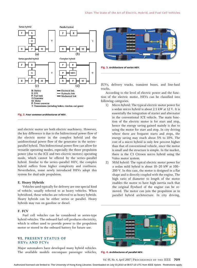
to any given driving condition.Traditionally, there are two basic categories of HEV,
namely series hybrids and parallel hybrids. In series HEV,
the ICE mechanical output is first converted to electricity
using a generator. The converted electricity either charges
the battery or bypasses the battery to propel the wheels via
an electric motor. This electric motor is also used to
capture the energy during braking. A parallel HEV, on the
other hand, has both the ICE and an electric motor coupledto the final drive shaft of the wheels via clutches. This
configuration allows the ICE and the electric motor to
deliver power to drive the wheels in combined mode, or
ICE alone, or motor alone modes. The electric motor is
also used for regenerative braking and for capturing the
excess energy of the ICE during coasting. Recently, series–
parallel and complex HEVs have been developed to
improve the power performance and fuel economy.
A. Series HEVIn series HEVs, the ICE mechanical output is first
converted into electricity using a generator. The converted
electricity either charges the battery or can bypass thebattery to propel the wheels via the same electric motor and
mechanical transmission. Conceptually, it is an ICE-assisted
EV that aims to extend the driving range comparable with
that of conventional vehicle. Due to the decoupling be-
tween the engine and the driving wheels, it has the definite
advantage of flexibility for locating the ICE generator set.
Although it has an added advantage of simplicity of its
drivetrain, it needs three propulsion devices, the ICE, thegenerator, and the electric motor. Therefore, the efficiency
of series HEV is generally lower. Another disadvantage is
that all these propulsion devices need to be sized for the
maximum sustained power if the series HEV is designed to
climb a long grade, making series HEV expensive. On the
other hand, when it is only needed to serve such short trips
as commuting to work and shopping, the corresponding
ICE generator set can adopt a lower rating.There are six possible different operation modes in a
series HEV:
1) battery alone mode: engine is off, vehicle is
powered by the battery only;
2) engine alone mode: power from ICE/G;
3) combined mode: both ICE/G set and battery
provides power to the traction motor;
4) power split mode: ICE/G power split to drive thevehicle and charge the battery;
5) stationary charging mode;
6) regenerative braking mode.
B. Parallel HEVDiffering from the series hybrid, the parallel HEV
allows both the ICE and electric motor to deliver power in
parallel to drive the wheels. Since both the ICE and electricmotor are generally coupled to the drive shaft of the wheels
via two clutches, the propulsion power may be supplied by
the ICE alone, by the electric motor, or by both. Con-
ceptually, it is inherently an electric-assisted ICEV for
achieving both lower emissions and fuel consumption. The
electric motor can be used as a generator to charge the
battery by regenerative braking or by absorbing power from
the ICE when its output is greater than that required todrive the wheels. Better than the series HEV, the parallel
hybrid needs only two propulsion devicesVthe ICE and
the electric motor. Another advantage over the series case
is that a smaller ICE and a smaller electric motor can be
used to get the same performance until the battery is
depleted. Even for long-trip operation, only the ICE needs
to be rated for the maximum sustained power while the
electric motor may still be about a half. The following arethe possible different operation modes of parallel hybrid:
1) motor alone mode: engine is off, vehicle is
powered by the motor only;
2) engine alone mode: vehicle is propelled by the
engine only;
3) combined mode: both ICE and motor provides
power to the drive the vehicle;
4) power split mode: ICE power is split to drive thevehicle and charge the battery (motor becomes
generator);
5) stationary charging mode;
6) regenerative braking mode (include hybrid brak-
ing mode).
C. Series–Parallel HEVIn the series–parallel hybrid, the configuration incor-
porates the features of both the series and parallel HEVs,
but involving an additional mechanical link compared with
the series hybrid and also an additional generator com-
pared with the parallel hybrid. Although possessing the
advantageous features of both the series and parallel HEVs,
the series–parallel HEV is relatively more complicated and
costly. Nevertheless, with the advances in control and
manufacturing technologies, some modern HEVs prefer toadopt this system.
D. Complex HEVAs reflected by its name, this system involves a complex
configuration that cannot be classified into the above three
kinds. As shown in Fig. 2(d), the complex hybrid seems to
be similar to the series–parallel hybrid, since the generator
Chan: The State of the Art of Electric, Hybrid, and Fuel Cell Vehicles
708 Proceedings of the IEEE | Vol. 95, No. 4, April 2007
Authorized licensed use limited to: The University of Hong Kong Libraries. Downloaded on July 03,2010 at 08:57:15 UTC from IEEE Xplore. Restrictions apply.
and electric motor are both electric machinery. However,
the key difference is due to the bidirectional power flow of
the electric motor in the complex hybrid and the
unidirectional power flow of the generator in the series–
parallel hybrid. This bidirectional power flow can allow for
versatile operating modes, especially the three propulsion
power (due to the ICE and two electric motors) operatingmode, which cannot be offered by the series–parallel
hybrid. Similar to the series–parallel HEV, the complex
hybrid suffers from higher complexity and costliness.
Nevertheless, some newly introduced HEVs adopt this
system for dual-axle propulsion.
E. Heavy HybridsVehicles used typically for delivery are one special kind
of vehicle, usually referred to as heavy vehicles. When
hybridized, these vehicles are referred to as heavy hybrids.
Heavy hybrids can be either series or parallel. Heavy
hybrids may run on gasoline or diesel.
F. FCVFuel cell vehicles can be considered as series-type
hybrid vehicles. The onboard fuel cell produces electricity,which is either used to provide power to the propulsion
motor or stored in the onboard battery for future use.
VI. PRESENT STATUS OFHEVs AND FCVs
Major automakers have developed many hybrid vehicles.
The available models encompass passenger vehicles,
SUVs, delivery trucks, transient buses, and line-haul
trucks.According to the level of electric power and the func-
tion of the electric motor, HEVs can be classified into
following categories.
1) Micro hybrid: The typical electric motor power for
a sedan micro hybrid is about 2.5 kW at 12 V. It is
essentially the integration of starter and alternator
in the conventional ICE vehicle. The main func-
tion of the electric motor is for start and stop,hence the energy saving gained mainly is due to
using the motor for start and stop. In city driving
where there are frequent starts and stops, the
energy saving may reach about 5% to 10%. The
cost of a micro hybrid is only few percent higher
than that of conventional vehicle, since the motor
is small and the structure is simple. In the market,
there is the C3 Citroen micro hybrid using theValeo motor system.
2) Mild hybrid: The typical electric motor power for
a sedan mild hybrid is about 10–20 kW at 100–
200 V. In this case, the motor is designed in a flat
shape and is directly coupled with the engine. The
high ratio of diameter to length of the motor
enables the motor to have high inertia such that
the original flywheel of the engine can be re-moved. The motor can join the propulsion as in
parallel hybrid architecture. In city driving,
Fig. 2. Four common architectures of HEV.
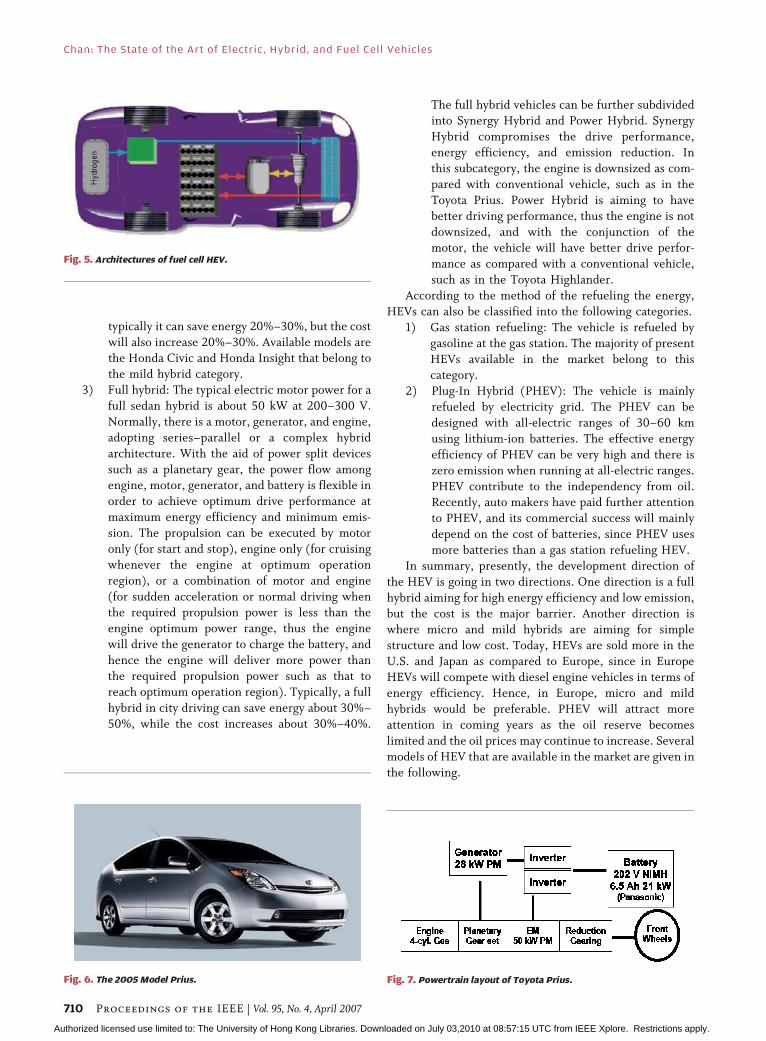
Fig. 3. Architecture of series HEV.
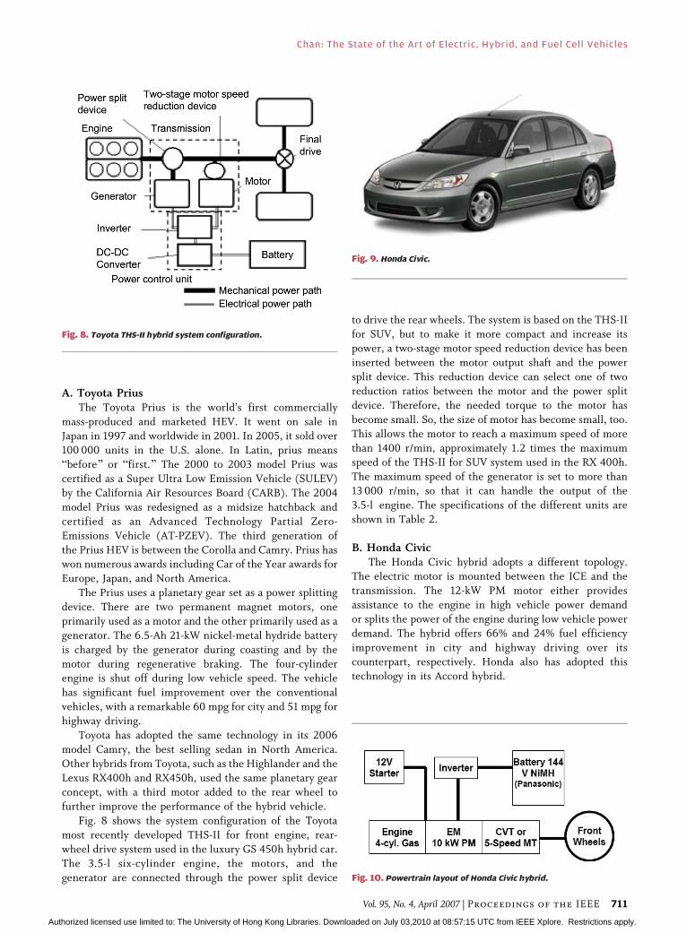
Fig. 4. Architectures of parallel HEV.
Chan: The State of the Art of Electric, Hybrid, and Fuel Cell Vehicles
Vol. 95, No. 4, April 2007 | Proceedings of the IEEE 709
Authorized licensed use limited to: The University of Hong Kong Libraries. Downloaded on July 03,2010 at 08:57:15 UTC from IEEE Xplore. Restrictions apply.
typically it can save energy 20%–30%, but the cost
will also increase 20%–30%. Available models arethe Honda Civic and Honda Insight that belong to
the mild hybrid category.
3) Full hybrid: The typical electric motor power for a
full sedan hybrid is about 50 kW at 200–300 V.
Normally, there is a motor, generator, and engine,
adopting series–parallel or a complex hybrid
architecture. With the aid of power split devices
such as a planetary gear, the power flow amongengine, motor, generator, and battery is flexible in
order to achieve optimum drive performance at
maximum energy efficiency and minimum emis-
sion. The propulsion can be executed by motor
only (for start and stop), engine only (for cruising
whenever the engine at optimum operation
region), or a combination of motor and engine
(for sudden acceleration or normal driving whenthe required propulsion power is less than the
engine optimum power range, thus the engine
will drive the generator to charge the battery, and
hence the engine will deliver more power than
the required propulsion power such as that to
reach optimum operation region). Typically, a full
hybrid in city driving can save energy about 30%–
50%, while the cost increases about 30%–40%.
The full hybrid vehicles can be further subdividedinto Synergy Hybrid and Power Hybrid. Synergy
Hybrid compromises the drive performance,
energy efficiency, and emission reduction. In
this subcategory, the engine is downsized as com-
pared with conventional vehicle, such as in the
Toyota Prius. Power Hybrid is aiming to have
better driving performance, thus the engine is not
downsized, and with the conjunction of themotor, the vehicle will have better drive perfor-
mance as compared with a conventional vehicle,
such as in the Toyota Highlander.
According to the method of the refueling the energy,
HEVs can also be classified into the following categories.
1) Gas station refueling: The vehicle is refueled by
gasoline at the gas station. The majority of present
HEVs available in the market belong to thiscategory.
2) Plug-In Hybrid (PHEV): The vehicle is mainly
refueled by electricity grid. The PHEV can be
designed with all-electric ranges of 30–60 km
using lithium-ion batteries. The effective energy
efficiency of PHEV can be very high and there is
zero emission when running at all-electric ranges.
PHEV contribute to the independency from oil.Recently, auto makers have paid further attention
to PHEV, and its commercial success will mainly
depend on the cost of batteries, since PHEV uses
more batteries than a gas station refueling HEV.
In summary, presently, the development direction of
the HEV is going in two directions. One direction is a full
hybrid aiming for high energy efficiency and low emission,
but the cost is the major barrier. Another direction iswhere micro and mild hybrids are aiming for simple
structure and low cost. Today, HEVs are sold more in the
U.S. and Japan as compared to Europe, since in Europe
HEVs will compete with diesel engine vehicles in terms of
energy efficiency. Hence, in Europe, micro and mild
hybrids would be preferable. PHEV will attract more
attention in coming years as the oil reserve becomes
limited and the oil prices may continue to increase. Severalmodels of HEV that are available in the market are given in
the following.
Fig. 7. Powertrain layout of Toyota Prius.
Fig. 5. Architectures of fuel cell HEV.
Fig. 6. The 2005 Model Prius.
Chan: The State of the Art of Electric, Hybrid, and Fuel Cell Vehicles
710 Proceedings of the IEEE | Vol. 95, No. 4, April 2007
Authorized licensed use limited to: The University of Hong Kong Libraries. Downloaded on July 03,2010 at 08:57:15 UTC from IEEE Xplore. Restrictions apply.
A. Toyota PriusThe Toyota Prius is the world’s first commercially
mass-produced and marketed HEV. It went on sale in
Japan in 1997 and worldwide in 2001. In 2005, it sold over100 000 units in the U.S. alone. In Latin, prius means
Bbefore[ or Bfirst.[ The 2000 to 2003 model Prius was
certified as a Super Ultra Low Emission Vehicle (SULEV)
by the California Air Resources Board (CARB). The 2004
model Prius was redesigned as a midsize hatchback and
certified as an Advanced Technology Partial Zero-
Emissions Vehicle (AT-PZEV). The third generation of
the Prius HEV is between the Corolla and Camry. Prius haswon numerous awards including Car of the Year awards for
Europe, Japan, and North America.
The Prius uses a planetary gear set as a power splitting
device. There are two permanent magnet motors, one
primarily used as a motor and the other primarily used as a
generator. The 6.5-Ah 21-kW nickel-metal hydride battery
is charged by the generator during coasting and by the
motor during regenerative braking. The four-cylinderengine is shut off during low vehicle speed. The vehicle
has significant fuel improvement over the conventional
vehicles, with a remarkable 60 mpg for city and 51 mpg for
highway driving.
Toyota has adopted the same technology in its 2006
model Camry, the best selling sedan in North America.
Other hybrids from Toyota, such as the Highlander and the
Lexus RX400h and RX450h, used the same planetary gearconcept, with a third motor added to the rear wheel to
further improve the performance of the hybrid vehicle.
Fig. 8 shows the system configuration of the Toyota
most recently developed THS-II for front engine, rear-
wheel drive system used in the luxury GS 450h hybrid car.
The 3.5-l six-cylinder engine, the motors, and the
generator are connected through the power split device
to drive the rear wheels. The system is based on the THS-II
for SUV, but to make it more compact and increase itspower, a two-stage motor speed reduction device has been
inserted between the motor output shaft and the power
split device. This reduction device can select one of two
reduction ratios between the motor and the power split
device. Therefore, the needed torque to the motor has
become small. So, the size of motor has become small, too.
This allows the motor to reach a maximum speed of more
than 1400 r/min, approximately 1.2 times the maximumspeed of the THS-II for SUV system used in the RX 400h.
The maximum speed of the generator is set to more than
13 000 r/min, so that it can handle the output of the
3.5-l engine. The specifications of the different units are
shown in Table 2.
B. Honda CivicThe Honda Civic hybrid adopts a different topology.
The electric motor is mounted between the ICE and the
transmission. The 12-kW PM motor either provides
assistance to the engine in high vehicle power demand
or splits the power of the engine during low vehicle power
demand. The hybrid offers 66% and 24% fuel efficiency
improvement in city and highway driving over its
counterpart, respectively. Honda also has adopted this
technology in its Accord hybrid.
Fig. 8. Toyota THS-II hybrid system configuration.
Fig. 9. Honda Civic.
Fig. 10. Powertrain layout of Honda Civic hybrid.
Chan: The State of the Art of Electric, Hybrid, and Fuel Cell Vehicles
Vol. 95, No. 4, April 2007 | Proceedings of the IEEE 711
Authorized licensed use limited to: The University of Hong Kong Libraries. Downloaded on July 03,2010 at 08:57:15 UTC from IEEE Xplore. Restrictions apply.

C. Ford EscapeFord produced the first SUV hybrid in the worldVthe
Escape. The Escape hybrid also adopted the planetary gear
concept as its power splitting device. With a significantly
reduced sized engine, this full size SUV hybrid provides
the same performance as its counterpart. The second
generation hybrid SUV at Ford, the Mercury Mariner, has
an improved power train design which offers exceptional
drivability and dynamic performance.
D. Saturn VueThe Saturn Vue simply added a 4-kW electric motor
through a belt to its existing powertrain. The small electric
motor is powered by a 36-V 10-kW nickel-metal hydride
battery. The motor provides 5 kW of electricity in a
generating mode either from the engine during opportu-
nity charging or from the vehicle braking. The surprising
20% fuel economy improvement justifies the smallinvestment into the hybrid. The drawback is that due to
the small size motor, the engine cannot be shut off at low
vehicle speed. The air conditioning is operated by the
engine, therefore, there will be no A/C even though the
engine can be turned off during idle.
E. ISE Transient BusThe transient buses are usually considered ideal
candidates for hybridization. The transient buses have
fixed routes and are almost driven in the stop-and-go
pattern. It is shown that an average 50% or more of fuel
can be saved with either parallel or series hybrids.
F. Honda FCXThere has been continuous progress in the fuel cell
vehicle development. One of the fuel cell vehicles that has
been commercially available is the Honda FCX. In 2002,
Honda’s FCX was certified by the U.S. Environmental
Protection Agency (EPA) and the California Air Resources
Board (CARB), making it the first and only fuel cell car in
history to be approved for commercial use. CARB and the
EPA have also certified the FCX as a Zero-EmissionVehicle (ZEV), Tier-2 Bin 1.
The 2005 and 2006 Honda FCX is powered by Honda
designed and manufactured fuel cell stacks. With an EPA
city/highway rating of 62/51 mpkg (57 mpkg combined), it
can achieve an EPA-rated driving range of 210 miles. In
terms of energy efficiency, one mile per kilogram (mpkg)
of hydrogen is almost equivalent to one mile per gallon
(mpg) of gasoline.
Fig. 11. Ford Escape SUV hybrid.
Fig. 12. Saturn Vue.
Fig. 13. ISE hybrid transient buses.
Fig. 14. ISE series hybrid system.
Chan: The State of the Art of Electric, Hybrid, and Fuel Cell Vehicles
712 Proceedings of the IEEE | Vol. 95, No. 4, April 2007
Authorized licensed use limited to: The University of Hong Kong Libraries. Downloaded on July 03,2010 at 08:57:15 UTC from IEEE Xplore. Restrictions apply.
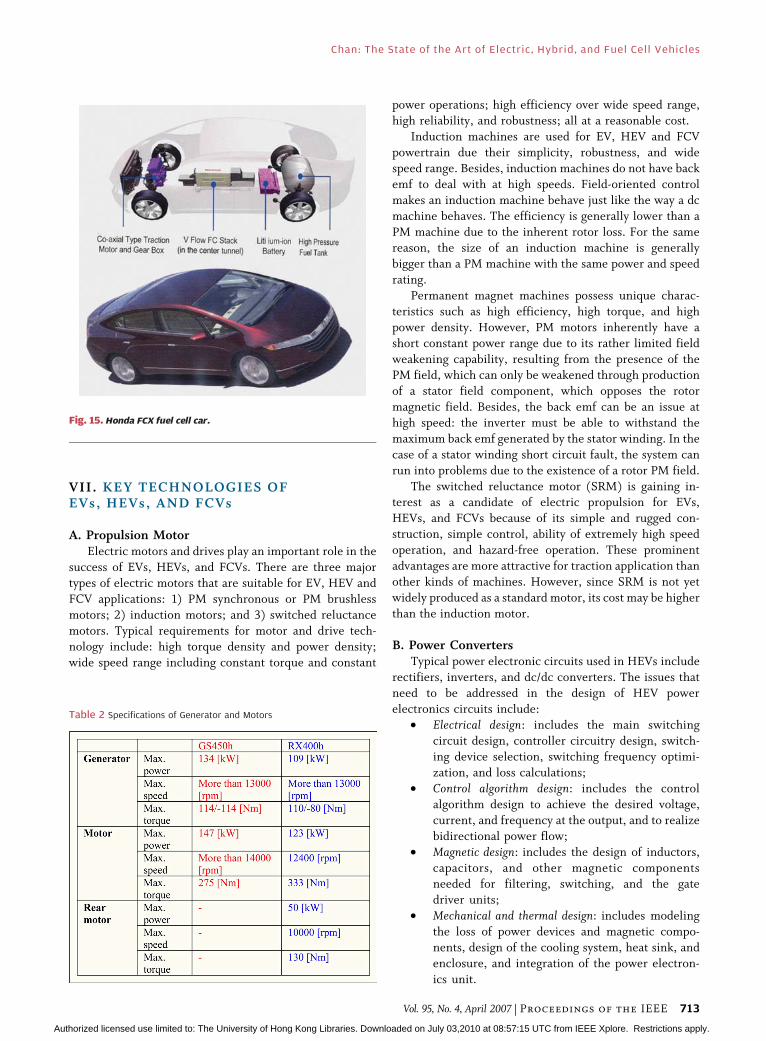
VII. KEY TECHNOLOGIES OFEVs, HEVs, AND FCVs
A. Propulsion MotorElectric motors and drives play an important role in the
success of EVs, HEVs, and FCVs. There are three major
types of electric motors that are suitable for EV, HEV and
FCV applications: 1) PM synchronous or PM brushless
motors; 2) induction motors; and 3) switched reluctance
motors. Typical requirements for motor and drive tech-nology include: high torque density and power density;
wide speed range including constant torque and constant
power operations; high efficiency over wide speed range,high reliability, and robustness; all at a reasonable cost.
Induction machines are used for EV, HEV and FCV
powertrain due their simplicity, robustness, and wide
speed range. Besides, induction machines do not have back
emf to deal with at high speeds. Field-oriented control
makes an induction machine behave just like the way a dc
machine behaves. The efficiency is generally lower than a
PM machine due to the inherent rotor loss. For the samereason, the size of an induction machine is generally
bigger than a PM machine with the same power and speed
rating.
Permanent magnet machines possess unique charac-
teristics such as high efficiency, high torque, and high
power density. However, PM motors inherently have a
short constant power range due to its rather limited field
weakening capability, resulting from the presence of thePM field, which can only be weakened through production
of a stator field component, which opposes the rotor
magnetic field. Besides, the back emf can be an issue at
high speed: the inverter must be able to withstand the
maximum back emf generated by the stator winding. In the
case of a stator winding short circuit fault, the system can
run into problems due to the existence of a rotor PM field.
The switched reluctance motor (SRM) is gaining in-terest as a candidate of electric propulsion for EVs,
HEVs, and FCVs because of its simple and rugged con-
struction, simple control, ability of extremely high speed
operation, and hazard-free operation. These prominent
advantages are more attractive for traction application than
other kinds of machines. However, since SRM is not yet
widely produced as a standard motor, its cost may be higher
than the induction motor.
B. Power ConvertersTypical power electronic circuits used in HEVs include
rectifiers, inverters, and dc/dc converters. The issues that
need to be addressed in the design of HEV power
electronics circuits include:
• Electrical design: includes the main switching
circuit design, controller circuitry design, switch-ing device selection, switching frequency optimi-
zation, and loss calculations;
• Control algorithm design: includes the control
algorithm design to achieve the desired voltage,
current, and frequency at the output, and to realize
bidirectional power flow;
• Magnetic design: includes the design of inductors,
capacitors, and other magnetic componentsneeded for filtering, switching, and the gate
driver units;
• Mechanical and thermal design: includes modeling
the loss of power devices and magnetic compo-
nents, design of the cooling system, heat sink, and
enclosure, and integration of the power electron-
ics unit.
Table 2 Specifications of Generator and Motors
Fig. 15. Honda FCX fuel cell car.
Chan: The State of the Art of Electric, Hybrid, and Fuel Cell Vehicles
Vol. 95, No. 4, April 2007 | Proceedings of the IEEE 713
Authorized licensed use limited to: The University of Hong Kong Libraries. Downloaded on July 03,2010 at 08:57:15 UTC from IEEE Xplore. Restrictions apply.
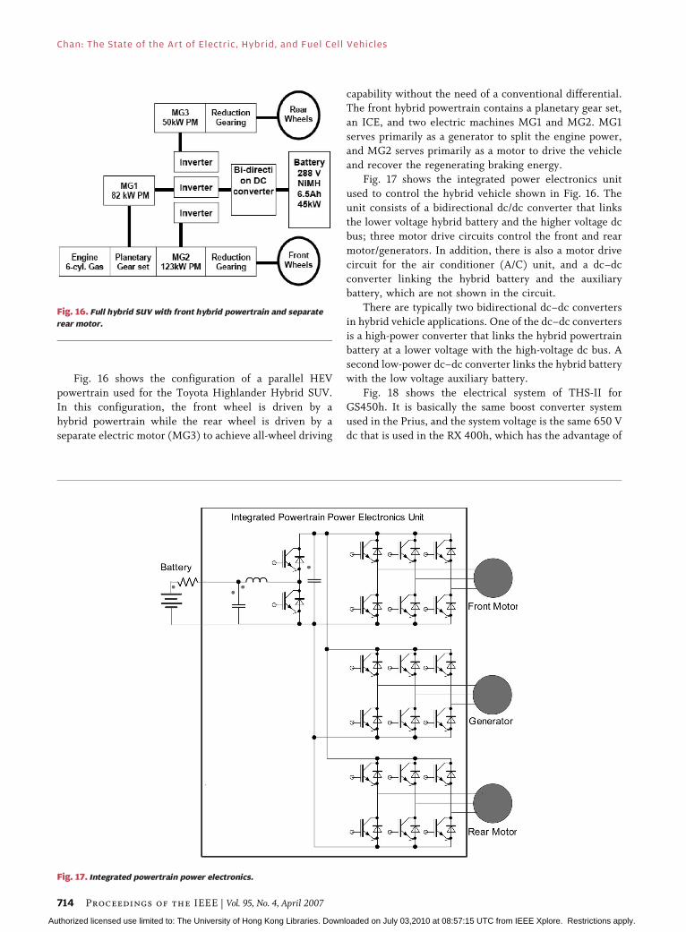
Fig. 16 shows the configuration of a parallel HEV
powertrain used for the Toyota Highlander Hybrid SUV.
In this configuration, the front wheel is driven by a
hybrid powertrain while the rear wheel is driven by a
separate electric motor (MG3) to achieve all-wheel driving
capability without the need of a conventional differential.The front hybrid powertrain contains a planetary gear set,
an ICE, and two electric machines MG1 and MG2. MG1
serves primarily as a generator to split the engine power,
and MG2 serves primarily as a motor to drive the vehicle
and recover the regenerating braking energy.
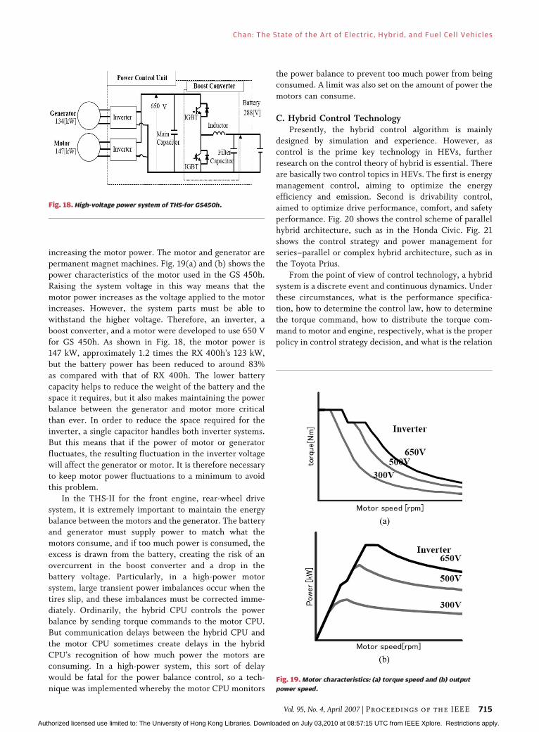
Fig. 17 shows the integrated power electronics unit
used to control the hybrid vehicle shown in Fig. 16. The
unit consists of a bidirectional dc/dc converter that linksthe lower voltage hybrid battery and the higher voltage dc
bus; three motor drive circuits control the front and rear
motor/generators. In addition, there is also a motor drive
circuit for the air conditioner (A/C) unit, and a dc–dc
converter linking the hybrid battery and the auxiliary
battery, which are not shown in the circuit.
There are typically two bidirectional dc–dc converters
in hybrid vehicle applications. One of the dc–dc convertersis a high-power converter that links the hybrid powertrain
battery at a lower voltage with the high-voltage dc bus. A
second low-power dc–dc converter links the hybrid battery
with the low voltage auxiliary battery.
Fig. 18 shows the electrical system of THS-II for
GS450h. It is basically the same boost converter system
used in the Prius, and the system voltage is the same 650 V
dc that is used in the RX 400h, which has the advantage of
Fig. 16. Full hybrid SUV with front hybrid powertrain and separate
rear motor.
Fig. 17. Integrated powertrain power electronics.
Chan: The State of the Art of Electric, Hybrid, and Fuel Cell Vehicles
714 Proceedings of the IEEE | Vol. 95, No. 4, April 2007
Authorized licensed use limited to: The University of Hong Kong Libraries. Downloaded on July 03,2010 at 08:57:15 UTC from IEEE Xplore. Restrictions apply.
increasing the motor power. The motor and generator arepermanent magnet machines. Fig. 19(a) and (b) shows the
power characteristics of the motor used in the GS 450h.
Raising the system voltage in this way means that the
motor power increases as the voltage applied to the motor
increases. However, the system parts must be able to
withstand the higher voltage. Therefore, an inverter, a
boost converter, and a motor were developed to use 650 V
for GS 450h. As shown in Fig. 18, the motor power is147 kW, approximately 1.2 times the RX 400h’s 123 kW,
but the battery power has been reduced to around 83%
as compared with that of RX 400h. The lower battery
capacity helps to reduce the weight of the battery and the
space it requires, but it also makes maintaining the power
balance between the generator and motor more critical
than ever. In order to reduce the space required for the
inverter, a single capacitor handles both inverter systems.But this means that if the power of motor or generator
fluctuates, the resulting fluctuation in the inverter voltage
will affect the generator or motor. It is therefore necessary
to keep motor power fluctuations to a minimum to avoid
this problem.
In the THS-II for the front engine, rear-wheel drive
system, it is extremely important to maintain the energy
balance between the motors and the generator. The batteryand generator must supply power to match what the
motors consume, and if too much power is consumed, the
excess is drawn from the battery, creating the risk of an
overcurrent in the boost converter and a drop in the
battery voltage. Particularly, in a high-power motor
system, large transient power imbalances occur when the
tires slip, and these imbalances must be corrected imme-
diately. Ordinarily, the hybrid CPU controls the powerbalance by sending torque commands to the motor CPU.
But communication delays between the hybrid CPU and
the motor CPU sometimes create delays in the hybrid
CPU’s recognition of how much power the motors are
consuming. In a high-power system, this sort of delay
would be fatal for the power balance control, so a tech-
nique was implemented whereby the motor CPU monitors
the power balance to prevent too much power from beingconsumed. A limit was also set on the amount of power the
motors can consume.
C. Hybrid Control TechnologyPresently, the hybrid control algorithm is mainly
designed by simulation and experience. However, as
control is the prime key technology in HEVs, further
research on the control theory of hybrid is essential. Thereare basically two control topics in HEVs. The first is energy
management control, aiming to optimize the energy
efficiency and emission. Second is drivability control,
aimed to optimize drive performance, comfort, and safety
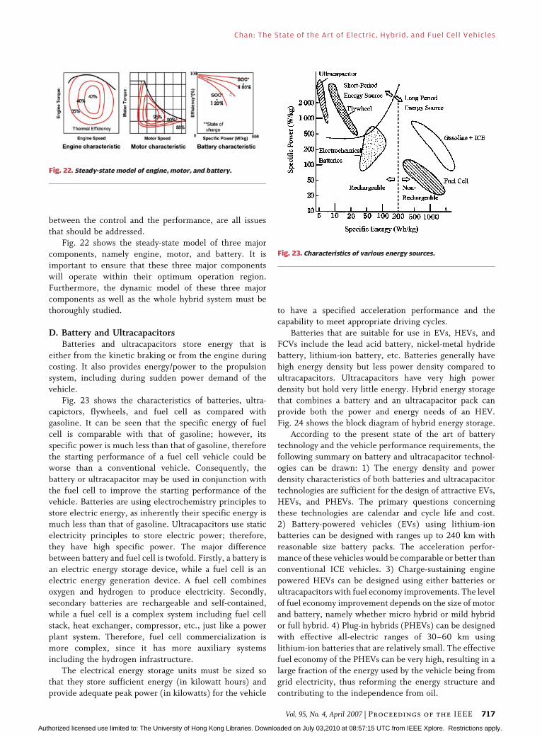
performance. Fig. 20 shows the control scheme of parallel
hybrid architecture, such as in the Honda Civic. Fig. 21
shows the control strategy and power management for
series–parallel or complex hybrid architecture, such as inthe Toyota Prius.
From the point of view of control technology, a hybrid
system is a discrete event and continuous dynamics. Under
these circumstances, what is the performance specifica-
tion, how to determine the control law, how to determine
the torque command, how to distribute the torque com-
mand to motor and engine, respectively, what is the proper
policy in control strategy decision, and what is the relation
Fig. 18. High-voltage power system of THS-for GS450h.
Fig. 19. Motor characteristics: (a) torque speed and (b) output
power speed.
Chan: The State of the Art of Electric, Hybrid, and Fuel Cell Vehicles
Vol. 95, No. 4, April 2007 | Proceedings of the IEEE 715
Authorized licensed use limited to: The University of Hong Kong Libraries. Downloaded on July 03,2010 at 08:57:15 UTC from IEEE Xplore. Restrictions apply.
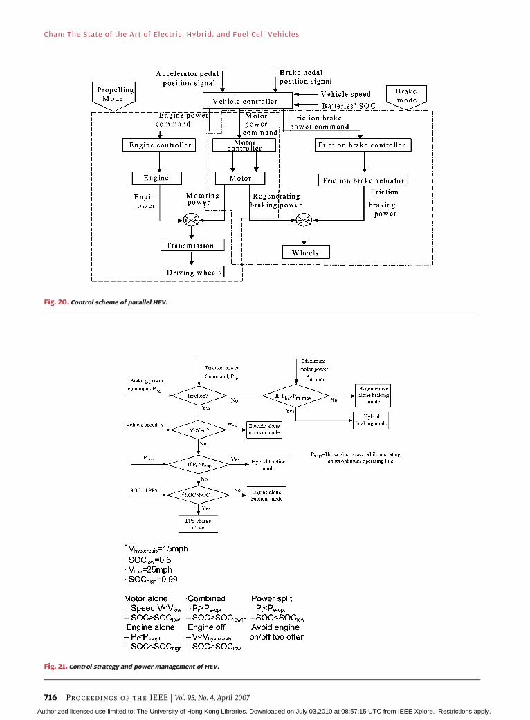
Fig. 20. Control scheme of parallel HEV.
Fig. 21. Control strategy and power management of HEV.
Chan: The State of the Art of Electric, Hybrid, and Fuel Cell Vehicles
716 Proceedings of the IEEE | Vol. 95, No. 4, April 2007
Authorized licensed use limited to: The University of Hong Kong Libraries. Downloaded on July 03,2010 at 08:57:15 UTC from IEEE Xplore. Restrictions apply.
between the control and the performance, are all issuesthat should be addressed.
Fig. 22 shows the steady-state model of three major
components, namely engine, motor, and battery. It is
important to ensure that these three major components
will operate within their optimum operation region.
Furthermore, the dynamic model of these three major
components as well as the whole hybrid system must be
thoroughly studied.
D. Battery and UltracapacitorsBatteries and ultracapacitors store energy that is
either from the kinetic braking or from the engine during
costing. It also provides energy/power to the propulsion
system, including during sudden power demand of the
vehicle.
Fig. 23 shows the characteristics of batteries, ultra-capictors, flywheels, and fuel cell as compared with
gasoline. It can be seen that the specific energy of fuel
cell is comparable with that of gasoline; however, its
specific power is much less than that of gasoline, therefore
the starting performance of a fuel cell vehicle could be
worse than a conventional vehicle. Consequently, the
battery or ultracapacitor may be used in conjunction with
the fuel cell to improve the starting performance of thevehicle. Batteries are using electrochemistry principles to
store electric energy, as inherently their specific energy is
much less than that of gasoline. Ultracapacitors use static
electricity principles to store electric power; therefore,
they have high specific power. The major difference
between battery and fuel cell is twofold. Firstly, a battery is
an electric energy storage device, while a fuel cell is an
electric energy generation device. A fuel cell combinesoxygen and hydrogen to produce electricity. Secondly,
secondary batteries are rechargeable and self-contained,
while a fuel cell is a complex system including fuel cell
stack, heat exchanger, compressor, etc., just like a power
plant system. Therefore, fuel cell commercialization is
more complex, since it has more auxiliary systems
including the hydrogen infrastructure.
The electrical energy storage units must be sized sothat they store sufficient energy (in kilowatt hours) and
provide adequate peak power (in kilowatts) for the vehicle
to have a specified acceleration performance and the
capability to meet appropriate driving cycles.
Batteries that are suitable for use in EVs, HEVs, andFCVs include the lead acid battery, nickel-metal hydride
battery, lithium-ion battery, etc. Batteries generally have
high energy density but less power density compared to
ultracapacitors. Ultracapacitors have very high power
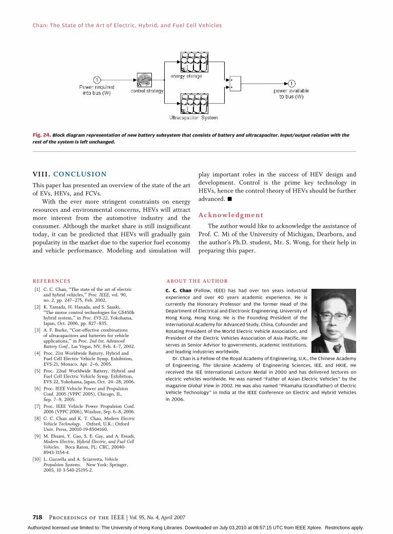
density but hold very little energy. Hybrid energy storage
that combines a battery and an ultracapacitor pack can
provide both the power and energy needs of an HEV.
Fig. 24 shows the block diagram of hybrid energy storage.According to the present state of the art of battery
technology and the vehicle performance requirements, the
following summary on battery and ultracapacitor technol-
ogies can be drawn: 1) The energy density and power
density characteristics of both batteries and ultracapacitor
technologies are sufficient for the design of attractive EVs,
HEVs, and PHEVs. The primary questions concerning
these technologies are calendar and cycle life and cost.2) Battery-powered vehicles (EVs) using lithium-ion
batteries can be designed with ranges up to 240 km with
reasonable size battery packs. The acceleration perfor-
mance of these vehicles would be comparable or better than
conventional ICE vehicles. 3) Charge-sustaining engine
powered HEVs can be designed using either batteries or
ultracapacitors with fuel economy improvements. The level
of fuel economy improvement depends on the size of motorand battery, namely whether micro hybrid or mild hybrid
or full hybrid. 4) Plug-in hybrids (PHEVs) can be designed
with effective all-electric ranges of 30–60 km using
lithium-ion batteries that are relatively small. The effective
fuel economy of the PHEVs can be very high, resulting in a
large fraction of the energy used by the vehicle being from
grid electricity, thus reforming the energy structure and
contributing to the independence from oil.
Fig. 22. Steady-state model of engine, motor, and battery.
Fig. 23. Characteristics of various energy sources.
Chan: The State of the Art of Electric, Hybrid, and Fuel Cell Vehicles
Vol. 95, No. 4, April 2007 | Proceedings of the IEEE 717
Authorized licensed use limited to: The University of Hong Kong Libraries. Downloaded on July 03,2010 at 08:57:15 UTC from IEEE Xplore. Restrictions apply.
VIII. CONCLUSION
This paper has presented an overview of the state of the art
of EVs, HEVs, and FCVs.
With the ever more stringent constraints on energy
resources and environmental concerns, HEVs will attract
more interest from the automotive industry and the
consumer. Although the market share is still insignificant
today, it can be predicted that HEVs will gradually gainpopularity in the market due to the superior fuel economy
and vehicle performance. Modeling and simulation will
play important roles in the success of HEV design and
development. Control is the prime key technology in
HEVs, hence the control theory of HEVs should be further
advanced. h
Acknowledgment
The author would like to acknowledge the assistance of
Prof. C. Mi of the University of Michigan, Dearborn, and
the author’s Ph.D. student, Mr. S. Wong, for their help in
preparing this paper.
REF ERENCE S
[1] C. C. Chan, BThe state of the art of electricand hybrid vehicles,[ Proc. IEEE, vol. 90,no. 2, pp. 247–275, Feb. 2002.
[2] K. Yamada, H. Hanada, and S. Sasaki,BThe motor control technologies for GS450hhybrid system,[ in Proc. EVS-22, Yokohama,Japan, Oct. 2006, pp. 827–835.
[3] A. F. Burke, BCost-effective combinationsof ultracapacitors and batteries for vehicleapplications,[ in Proc. 2nd Int. AdvancedBattery Conf., Las Vegas, NV, Feb. 4–7, 2002.
[4] Proc. 21st Worldwide Battery, Hybrid andFuel Cell Electric Vehicle Symp. Exhibition,EVS-21, Monaco, Apr. 2–6, 2005.
[5] Proc. 22nd Worldwide Battery, Hybrid andFuel Cell Electric Vehicle Symp. Exhibition,EVS-22, Yokohama, Japan, Oct. 24–28, 2006.
[6] Proc. IEEE Vehicle Power and PropulsionConf. 2005 (VPPC 2005), Chicago, IL,Sep. 7–9, 2005.
[7] Proc. IEEE Vehicle Power Propulsion Conf.2006 (VPPC 2006), Windsor, Sep. 6–8, 2006.
[8] C. C. Chan and K. T. Chau, Modern ElectricVehicle Technology. Oxford, U.K.: OxfordUniv. Press, 20010-19-8504160.
[9] M. Ehsani, Y. Gao, S. E. Gay, and A. Emadi,Modern Electric, Hybrid Electric, and Fuel CellVehicles. Boca Raton, FL: CRC, 20040-8943-3154-4.
[10] L. Guzzella and A. Sciarretta, VehiclePropulsion Systems. New York: Springer,2005, 10 3-540-25195-2.
AB OUT THE AUT HOR
C. C. Chan (Fellow, IEEE) has had over ten years industrial
experience and over 40 years academic experience. He is
currently the Honorary Professor and the former Head of the
Department of Electrical and Electronic Engineering, University of
Hong Kong, Hong Kong. He is the Founding President of the
International Academy for Advanced Study, China, Cofounder and
Rotating President of the World Electric Vehicle Association, and
President of the Electric Vehicles Association of Asia Pacific. He
serves as Senior Advisor to governments, academic institutions,
and leading industries worldwide.
Dr. Chan is a Fellow of the Royal Academy of Engineering, U.K., the Chinese Academy
of Engineering, The Ukraine Academy of Engineering Sciences, IEE, and HKIE. He
received the IEE International Lecture Medal in 2000 and has delivered lectures on
electric vehicles worldwide. He was named BFather of Asian Electric Vehicles[ by the
magazine Global View in 2002. He was also named BPitamaha (Grandfather) of Electric
Vehicle Technology[ in India at the IEEE Conference on Electric and Hybrid Vehicles
in 2006.
Fig. 24. Block diagram representation of new battery subsystem that consists of battery and ultracapacitor. Input/output relation with the
rest of the system is left unchanged.
Chan: The State of the Art of Electric, Hybrid, and Fuel Cell Vehicles
718 Proceedings of the IEEE | Vol. 95, No. 4, April 2007
Authorized licensed use limited to: The University of Hong Kong Libraries. Downloaded on July 03,2010 at 08:57:15 UTC from IEEE Xplore. Restrictions apply.