Embed Size (px)
Citation preview
1
Paper Number: 106
Title: A Continuum Damage Mechanics Model to Predict Kink-Band
Propagation Using Deformation Gradient Tensor Decomposition
Authors: Andrew C. Bergan
Frank A. Leone Jr.
https://ntrs.nasa.gov/search.jsp?R=20160012045 2018-07-16T11:12:03+00:00Z

2
ABSTRACT
A new model is proposed that represents the kinematics of kink-band formation and
propagation within the framework of a mesoscale continuum damage mechanics
(CDM) model. The model uses the recently proposed deformation gradient
decomposition approach to represent a kink band as a displacement jump via a cohesive
interface that is embedded in an elastic bulk material. The model is capable of
representing the combination of matrix failure in the frame of a misaligned fiber and
instability due to shear nonlinearity. In contrast to conventional linear or bilinear strain
softening laws used in most mesoscale CDM models for longitudinal compression, the
constitutive response of the proposed model includes features predicted by detailed
micromechanical models. These features include: 1) the rotational kinematics of the
kink band, 2) an instability when the peak load is reached, and 3) a nonzero plateau
stress under large strains.
INTRODUCTION
Composite plies in laminates loaded under longitudinal compression often fail by
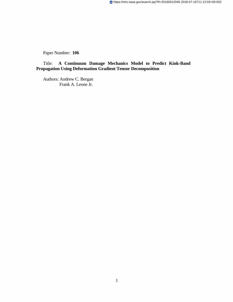
the kink-band damage mechanism [1]–[4]. A typical kink band is shown in Figure 1
along with the parameters often used to describe the kink band: 𝑤KB for the width of the
kink band, 𝜑 for the fiber misalignment angle, and 𝛽 for the kink-band inclination angle.
While failure criteria [5]–[9] and micromechanical models [10]–[14] have been
developed with special consideration for the kinematics of kink bands, the majority of
corresponding mesoscale damage propagation models utilize phenomenological
softening laws that mirror the approach used for longitudinal tensile damage
propagation [15]–[18]. Evaluations have shown that these existing phenomenological
models that rely on linear or bilinear softening laws do not predict compressive failures
accurately [19].
_____________
Andrew C Bergan, Structural Mechanics and Concepts Branch, NASA Langley Research Center, Mail Stop 190, Hampton, VA 23681, U.S.A. Frank A. Leone, Jr., Structural Mechanics and Concepts Branch, NASA Langley Research Center, Mail Stop 190, Hampton, VA 23681, U.S.A.
3
Many authors have contributed theoretical models that describe the formation of
kink bands [20]. Argon [21] proposed that an initial fiber misalignment introduces shear
stresses, which rotate fibers, further increasing shear stresses until failure is reached.
Several authors subsequently recognized the importance of shear nonlinearity to the
prediction of kink bands, e.g., [22]–[25]. The Langley Research Center (LaRC) failure
criteria added the notions of 1) evaluating a matrix failure criterion in the misaligned
fiber direction and 2) consideration of the competition between matrix cracking and
instability due to shear nonlinearity for the prediction of strength [5], [6].
Two authors have proposed mesoscale models that include the post peak response.
Basu et al. introduced a model that used Schapery Theory and stress transformations
and showed the importance of considering multi-axial stress states [26]. Costa et al.
recently extended these concepts to account for the post-peak response considering
matrix damage, shear nonlinearity, and friction while also addressing the need for
special considerations to achieve mesh objectivity [27].
The purpose of this paper is to propose a mesoscale continuum damage mechanics
(CDM) model for longitudinal compression based on the assumptions of the LaRC
failure criteria. The deformation gradient decomposition (DGD) method [28] is used for
accurate representation of the kink band and fiber misalignments.
MODEL OVERVIEW
The model formulation and implementation are described in this section. It is
assumed that the kink-band plane occurs in the 1-2 plane to simplify the derivation. The
model formulation can be extended to consider out-of-plane kinking by adding a
criterion for the kinking plane angle as described in LaRC04 [6].
Figure 1. Kink band.
(a) Photomicrograph of a
kink band [15]
(b) Conventional
representation of a kink band
4
Idealization of the Kink-Band Formation Process
The idealization of the kink-band formation process builds on Argon’s hypothesis
that an initial fiber misalignment leads to fiber rotation and increasing shear stress in the
matrix, eventually initiating matrix failure. Recent, detailed experimental investigations
have revealed that Mode II microcracks form between the fibers during kink band
formation, e.g., [29]. The formation of matrix cracks as a result of fiber rotation is
consistent with the LaRC03 model proposed by Dávila and Camanho [5], which builds
on Argon’s model by evaluating a matrix failure criterion in the coordinate frame of the
rotated (misaligned) fibers. Pinho et al. [6] extended this concept in the LaRC04 model
by adding shear-nonlinearity. Additionally, Pinho et al. proposed that kink bands initiate
due to one of two competing failure mechanisms: 1) matrix failure or 2) instability due
to shear nonlinearity. The model proposed here accounts for the initiation and evolution
of both of these mechanisms (matrix failure and instability due to shear nonlinearity)
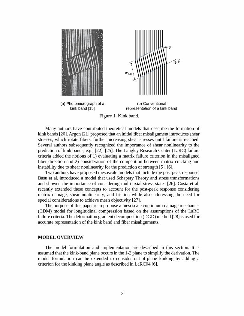
within the framework of a mesoscale CDM. The model collapses matrix cracks on a
single cohesive interface that is embedded within a bulk material, as shown in Figure 2.
Furthermore, the model assumes that bending of the fibers and the kink-band inclination
angle can be ignored, as presumed by the idealization shown in Figure 2. The bulk
material is represented with a constitutive model that includes shear nonlinearity.
Figure 2. Splitting microcracks in-between fibers are lumped into a cohesive
interface that is embedded within a bulk material.
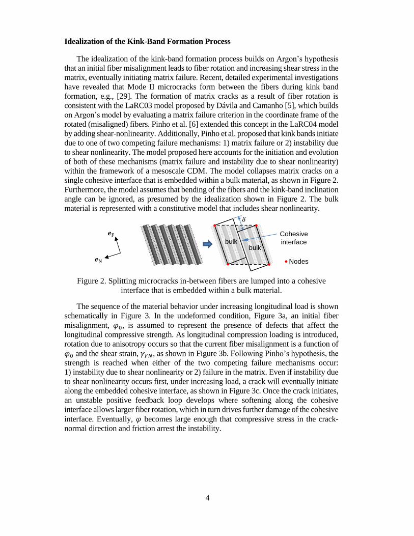
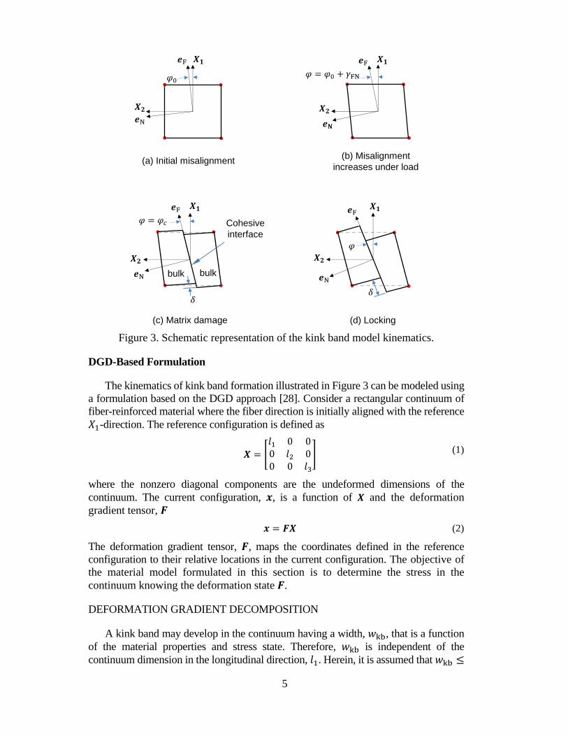
The sequence of the material behavior under increasing longitudinal load is shown
schematically in Figure 3. In the undeformed condition, Figure 3a, an initial fiber
misalignment, 𝜑0, is assumed to represent the presence of defects that affect the
longitudinal compressive strength. As longitudinal compression loading is introduced,
rotation due to anisotropy occurs so that the current fiber misalignment is a function of
𝜑0 and the shear strain, 𝛾𝐹𝑁, as shown in Figure 3b. Following Pinho’s hypothesis, the
strength is reached when either of the two competing failure mechanisms occur:
1) instability due to shear nonlinearity or 2) failure in the matrix. Even if instability due
to shear nonlinearity occurs first, under increasing load, a crack will eventually initiate
along the embedded cohesive interface, as shown in Figure 3c. Once the crack initiates,
an unstable positive feedback loop develops where softening along the cohesive
interface allows larger fiber rotation, which in turn drives further damage of the cohesive
interface. Eventually, 𝜑 becomes large enough that compressive stress in the crack-
normal direction and friction arrest the instability.
bulkbulk
Nodes
Cohesive
interface
5
Figure 3. Schematic representation of the kink band model kinematics.
DGD-Based Formulation
The kinematics of kink band formation illustrated in Figure 3 can be modeled using
a formulation based on the DGD approach [28]. Consider a rectangular continuum of
fiber-reinforced material where the fiber direction is initially aligned with the reference
𝑋1-direction. The reference configuration is defined as
𝑿 = [
𝑙1 0 00 𝑙2 00 0 𝑙3
] (1)
where the nonzero diagonal components are the undeformed dimensions of the
continuum. The current configuration, 𝒙, is a function of 𝑿 and the deformation
gradient tensor, 𝑭
𝒙 = 𝑭𝑿 (2)
The deformation gradient tensor, 𝑭, maps the coordinates defined in the reference
configuration to their relative locations in the current configuration. The objective of
the material model formulated in this section is to determine the stress in the
continuum knowing the deformation state 𝑭.
DEFORMATION GRADIENT DECOMPOSITION
A kink band may develop in the continuum having a width, 𝑤kb, that is a function
of the material properties and stress state. Therefore, 𝑤kb is independent of the
continuum dimension in the longitudinal direction, 𝑙1. Herein, it is assumed that 𝑤kb ≤
(a) Initial misalignment(b) Misalignment
increases under load
(d) Locking(c) Matrix damage
bulk bulk
Cohesive
interface
6
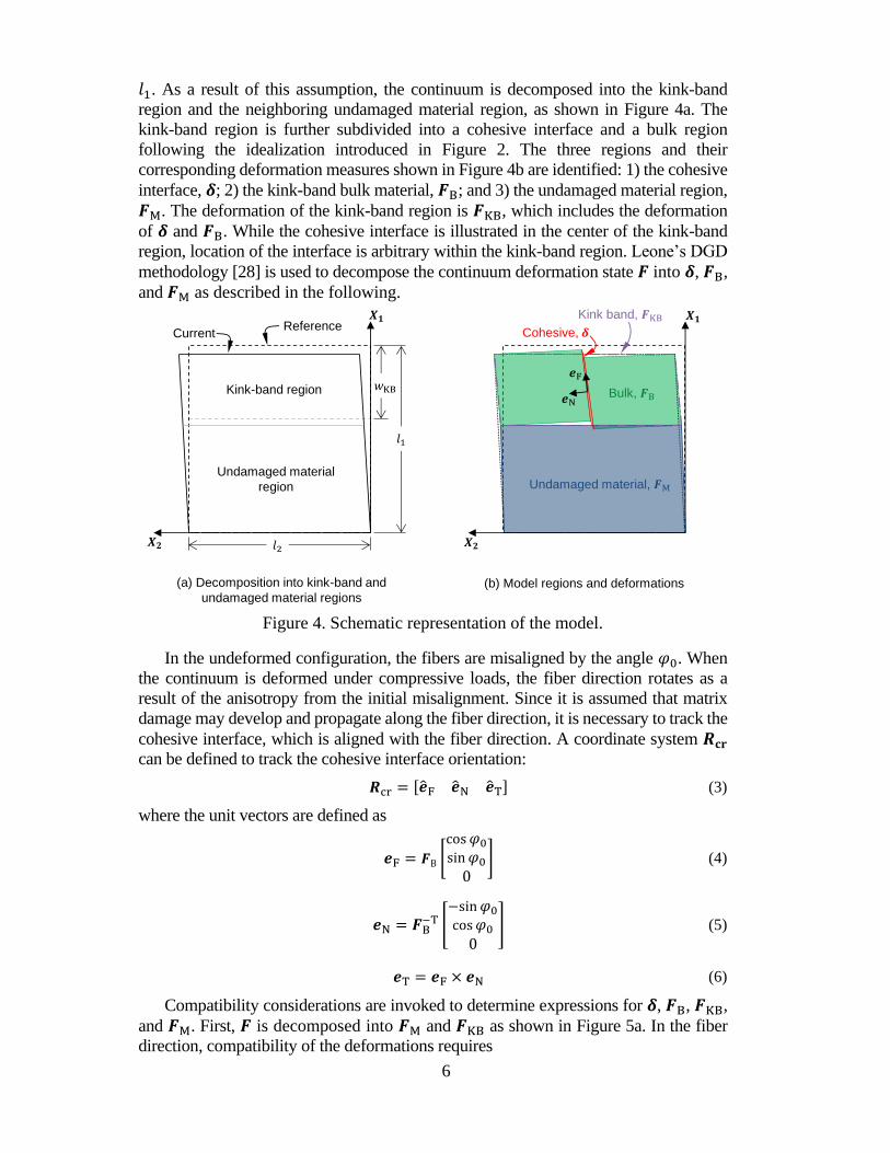
𝑙1. As a result of this assumption, the continuum is decomposed into the kink-band
region and the neighboring undamaged material region, as shown in Figure 4a. The
kink-band region is further subdivided into a cohesive interface and a bulk region
following the idealization introduced in Figure 2. The three regions and their
corresponding deformation measures shown in Figure 4b are identified: 1) the cohesive
interface, 𝜹; 2) the kink-band bulk material, 𝑭B; and 3) the undamaged material region,
𝑭M. The deformation of the kink-band region is 𝑭KB, which includes the deformation
of 𝜹 and 𝑭B. While the cohesive interface is illustrated in the center of the kink-band
region, location of the interface is arbitrary within the kink-band region. Leone’s DGD
methodology [28] is used to decompose the continuum deformation state 𝑭 into 𝜹, 𝑭B,
and 𝑭M as described in the following.
Figure 4. Schematic representation of the model.
In the undeformed configuration, the fibers are misaligned by the angle 𝜑0. When
the continuum is deformed under compressive loads, the fiber direction rotates as a
result of the anisotropy from the initial misalignment. Since it is assumed that matrix
damage may develop and propagate along the fiber direction, it is necessary to track the
cohesive interface, which is aligned with the fiber direction. A coordinate system 𝑹𝐜𝐫
can be defined to track the cohesive interface orientation:
𝑹cr = [�̂�F �̂�N �̂�T] (3)
where the unit vectors are defined as
𝒆F = 𝑭B [cos𝜑0
sin𝜑0
0] (4)
𝒆N = 𝑭B−T [
−sin𝜑0
cos𝜑0
0] (5)
𝒆T = 𝒆F × 𝒆N (6)
Compatibility considerations are invoked to determine expressions for 𝜹, 𝑭B, 𝑭KB,
and 𝑭M. First, 𝑭 is decomposed into 𝑭M and 𝑭KB as shown in Figure 5a. In the fiber
direction, compatibility of the deformations requires
Undamaged material,
Cohesive,
Bulk,
ReferenceCurrent
Kink-band region
Undamaged material
region
Kink band,
(a) Decomposition into kink-band and
undamaged material regions(b) Model regions and deformations
7
𝒙(1) = (1 − 𝜔KB)𝒙M(1)
+ 𝜔KB𝒙KB(1)
(7)
where the superscript (1) indicates the first column of 𝒙 and 𝜔KB is the normalized width
of the kink band, 𝜔KB = 𝑤KB 𝑙1⁄ . Substituting equations (2) and (1) into equation (7)
𝑭𝑿(1) = (1 − 𝜔KB)𝑭M𝑿(1) + 𝜔KB𝑭KB𝑿
(1) (8)
then simplifying and rearranging yields an expression for 𝑭KB(1)
:
𝑭KB(1)
=1
𝜔KB𝑭(1) + (1 −
1
𝜔KB)𝑭M
(1) (9)
In the 2-direction, there is no decomposition, so compatibility of the deformation
requires
𝒙KB(2)
= 𝒙M(2)
= 𝒙(2) (10)
Substituting equation (2) into (10) and simplifying yields
𝑭KB(2)
= 𝑭M(2)
= 𝑭(2) (11)
Similarly, 𝑭KB is decomposed into 𝜹 and 𝑭B as shown in Figure 5b. Again,
compatibility considerations introduce relationships in the fiber direction and in the
transverse directions. In the fiber direction,
𝑭B(1)
= 𝑭KB(1)
(12)
In the crack-normal direction,
𝒙KB(2)
= 𝒙B(2)
+ 𝑹cr𝜹 (13)
Substituting equation (2) into (13)
𝑭KB𝑿(2) = 𝑭B𝑿
(2) + 𝑹cr𝜹 (14)
and rearranging yields
𝜹 = 𝑹crT (𝑭B
(2)− 𝑭(2)) 𝑙2 (15)
Using equations (9) – (11), (12), and (15) with 𝑭 provided as an input, the quantities
𝜹, 𝑭B, 𝑭KB, and 𝑭M can be determined in terms of 𝑭B(2)
and 𝑭M(1)
.

8
Figure 5. Decomposition of the continuum.
EQUILIBRIUM AND SOLUTION PROCEDURE
It is necessary to ensure that the tractions that arise in the cohesive interface, kink-
band bulk, and neighboring material are in equilibrium. Equilibrium is enforced 1)
between the cohesive interface and the kink-band bulk material in the crack-normal
direction, �̂�N and 2) between the kink-band region and the neighboring material in the
fiber direction, �̂�F.
First, the tractions on the cohesive interface are derived as follows. The cohesive
stress vector 𝝉COH is determined using the cohesive damage model proposed by Turon
et al. [30]. The cohesive stress vector 𝝉COH is defined as
𝝉COH = [
𝑘F(1 − 𝑑𝑚)𝛿F𝑘N(1 − 𝑑𝑚)𝛿N − 𝑘N𝑑𝑚⟨−𝛿N⟩
𝑘T(1 − 𝑑𝑚)𝛿T
] (16)
where 𝛿F, 𝛿N, and 𝛿T are the components of 𝜹 along the fiber, crack-normal, and
transverse directions, respectively; 𝑘F, 𝑘N, and 𝑘T are the cohesive penalty stiffnesses
in the fiber, crack-normal, and transverse directions, respectively; 𝑑𝑚 is the scalar
cohesive damage variable; and the operator ⟨𝑥⟩ is defined as ⟨𝑥⟩ = (𝑥 + |𝑥|)/2. The
stress in the kink-band bulk is determined from 𝑭B using Green-Lagrange strain and
Hooke’s Law as
𝑬B =1
2(𝑭B
T𝑭B − 𝑰) −𝛾PL2
[0 1 01 0 00 0 0
] (17)
𝑺B = 𝑪𝜑0: 𝑬B (18)
where 𝑬B is the Green-Lagrange strain, 𝑰 is the identity tensor, 𝑺B is the 2nd Piola-
Kirchhoff stress, 𝑪𝜑0 is the stiffness tensor rotated about the transverse direction by
𝜑0 following classical lamination theory (see, e.g., [31]), and 𝛾PL is the plastic portion
of the shear strain (𝛾 = 𝛾EL+ 𝛾
PL). A variation of the Ramberg-Osgood model [32]
𝛾12 =1
𝐺12[𝜏12 + 𝛼PLsign(𝜏12)|𝜏12|
𝑛PL] (19)
Undamaged material,
, ,
Kink band, ,
(a) Decomposition of into and (b) Decomposition of into and

9
is used to represent shear-nonlinearity in the bulk material. The plastic portion of the
shear strain 𝛾PL is found through iteration and is removed from the strain tensor as
shown in equation (17). By transforming 𝑺B to Cauchy stress as
𝝈B = 𝑭B𝑺B𝑭BT|𝑭B|
−1 (20)
Cauchy’s stress theorem can be used to find the stress vector acting on the cohesive
interface:
𝒕B = 𝝈B ∙ �̂�N (21)
Likewise, the tractions for equilibrium between the kink-band region and the
neighboring material in the fiber direction are derived as follows. In the neighboring
material, the Cauchy stress is
𝝈M = 𝑭M𝑺M𝑭MT |𝑭M|
−1 (22)
where
𝑺M = 𝑪𝜑0: 𝑬M (23)
𝑬M =1
2(𝑭M
T 𝑭M − 𝑰) −𝛾PL2
[0 1 01 0 00 0 0
] (24)
Cauchy’s stress theorem is used to obtain the stress vector acting on a plane defined by
the fiber direction in the kink-band:
𝒕M = 𝝈M ∙ �̂�𝑭 (25)
The corresponding traction due to the stress in the kink-band region is
𝒕KB = 𝝈B ∙ �̂�𝑭 (26)
An iterative solution procedure is required to solve for the state of stress at
equilibrium. A residual stress vector 𝝈res is defined in terms of the stress vectors in
equations (16), (21), (25), and (26) in the current crack coordinate system as
𝝈res = [𝑹crT (𝒕M − 𝒕KB)
𝝉COH − 𝑹crT 𝒕B
] (27)
where the unknown variables are
𝒙eq = [𝑭M(1)
𝑭B(2)] (28)
The Newton-Raphson method is used following
𝒙eq,new = 𝒙eq − (𝜕𝝈res
𝜕𝒙eq)−1
𝝈res (29)
to find a converged solution for 𝒙eq by iterating until the norm of 𝝈res is less than a
tolerance value (in this case, set to 0.01% of the Mode I cohesive strength). After the
converged solution is found, the cohesive damage model is evaluated to determine 𝑑𝑚
for the current 𝜹. If 𝑑𝑚 increases, a new converged deformation state is sought for the
updated 𝑑𝑚 using equation (29). If 𝑑𝑚 does not increase, a solution for the current 𝑭
has been found and the stress in the kink-band bulk material is returned.

10
FRICTION ACTING ON THE CRACK
Compressive failures, whether matrix or fiber dominated, often propagate unstably.
Friction on the fracture surfaces can stabilize these failure processes. As a result,
accounting for friction on compressively loaded cracks can have a significant effect on
the structural response.
In order to predict matrix cracking while under compressive loading, it is important
to account for the effects of friction on the potential fracture planes. Prior to failure
initiation, compressive stresses on a fracture plane are known to increase the effective
shear strength (e.g., [6], [33]). Camanho et al. [17] accounted for this increased effective
shear strength for matrix cracks in his smeared crack continuum damage mechanics
model. In the present model, the approach of Camanho et al. is used to predict the 𝜎12
vs. 𝜎22 failure initiation envelope of LaRC04.
In order to account for the effects of friction on the matrix cracks after initiation,
features of the cohesive zone model of Alfano and Sacco [34] were applied. In the
Alfano-Sacco model, friction acts only on the damaged portion of a cohesive zone
element, which causes the surface area on which friction acts to increase as the cohesive
damage variable increases. A single, constant coefficient of friction is assumed.
DEMONSTRATION AND DISCUSSION
The proposed model is demonstrated in this section. The model was implemented
as VUMAT in Abaqus [35]. Several features of the model are highlighted in this section
through single element analyses. The contributions of the initial misalignment angle,
the cohesive interface fracture toughness, and the coefficient of friction to the
constitutive response of the model are investigated. The material properties for IM7-
8552 used in this section are summarized in Table I. The width of the kink band was
assumed to be 0.1 mm. A single element (C3D8R) model was used with uniform end
shortening displacement applied to the longitudinal direction. The element size was 0.15
mm on all sides. The applied displacement was reacted by simply supported boundary
conditions on the opposite face.

11
TABLE I. IM7-8552 MATERIAL PROPERTIES.
Property Value Units Source
𝐸11 171420 MPa [36]
𝐸22 9080 MPa [36]
𝐺12 5290 MPa [36]
𝜈12 0.32 - [36]
𝜈23 0.52 - [17]
𝛼PL 4.41 × 10⁻¹⁰ MPa1−𝜂PL [37]
𝑛PL 5.934 - [37]
𝑋𝐶 1200 MPa [17]
𝑌𝐶 199.8 MPa [36]
𝑆𝐿 92.3 MPa [36]
𝑌𝑇 62.3 MPa [36]
𝐺𝐼𝑐 0.277 N/mm [17]
𝐺𝐼𝐼𝑐 0.788 N/mm [17]
𝜂BK 1.634 - [17]
𝜇 0.3 - Assumed
Initial Misalignment Angle
As with many failure criteria for longitudinal compression failure, the present model
assumes an initial fiber misalignment angle 𝜑0. The effect of 𝜑0 is illustrated in Figure
6 for a range of values where the longitudinal stress (𝜎11 = 𝑅𝐹1 𝐴⁄ ) normalized to the
strength is plotted as a function of applied longitudinal strain. The analyses were
terminated when the matrix failure criterion was satisfied on the cohesive interface,
which occurred in all cases.
Figure 6. Effect of 𝜑0 on the predicted response. Results are truncated at the point
when matrix failure initiates.
0.0
0.2
0.4
0.6
0.8
1.0
1.2
1.4
1.6
0.0 0.2 0.4 0.6 0.8 1.0 1.2
σxx/X
C
d/l [%]
phi0 = 1.5 phi0 = 2.0 phi0 = 2.2 phi0 = 2.5
phi0 = 3.0 phi0 = 4.0 phi0 = 5.0
[%]
1.5
2.0
2.2
3.0
4.0
5.0
2.5

12
Pinho et al. [6] and Camanho et al. [9] proposed procedures to determine the 𝜑0 that
corresponds to a measured strength 𝑋𝐶 taking into account shear nonlinearity. In both
cases, 𝜑0 is obtained from
𝜑0 = 𝜑𝑐 − 𝛾𝐹𝑁 (30)
where 𝜑𝑐 is the rotation of the fibers when the strength 𝑋𝐶 is reached for a uniaxial stress
state. The values of 𝜑0 calculated following Pinho et al. [6] and Camanho et al. [9] for
the material properties in Table I are similar: 3.5° and 3.4°, respectively. For both these
values of 𝜑0, the present model underpredicts the strength significantly, as shown in
Figure 6. Also, in both cases, the present model predicts that instability due to shear
nonlinearity occurs before matrix failure, as can be observed in Figure 6 by the gradual
unloading after the peak load prior to failure initiation in the matrix.
A graphical comparison of the shear nonlinearity stress-strain curve based on
equation (19), and the applied shear stress provides insight into the transition between
instability due to shear nonlinearity and matrix failure, as proposed in [6]. For uniaxial
compressive loading with 𝜎11 = 𝑋𝐶, the shear stress in the misaligned frame can be
obtained from a stress transformation by the angle 𝜑 = 𝜑0 + 𝛾:
𝜏 =1
2sin(2(𝜑0 + 𝛾))𝑋𝐶 (31)
The graphical comparison of equations (19) and (31) for the material properties
considered here is shown in Figure 7. Equation (31) is plotted in Figure 7 with several
values for 𝜑0. According to [6], matrix failure occurs prior to instability for values of
𝜑0 that intersect the shear stress-strain curve (i.e., 𝜑0 = 1.5° in Figure 7), and failure
occurs by instability when equation (31) does not intersect with the shear stress-strain
curve (e.g. 𝜑0 > 2.2°). Such is the case here for the values of 𝜑0 = 3.5° or 3.4°
calculated using equation (30). Therefore, a different criterion is required to determine
𝜑0 in the case of shear instability.
Figure 7. Criterion for matrix failure vs. instability due to shear nonlinearity, where
the transition between modes occurs for the 𝜑0 that makes the results from
equation (31) tangent to equation (19), after [6].
[%]
1.5
2.2
3.0
4.0
Equation (19)
0.0
0.2
0.4
0.6
0.8
1.0
1.2
1.4
1.6
1.8
2.0
0.0 1.0 2.0 3.0 4.0 5.0 6.0 7.0 8.0
τ12/S
L
γ12 [%]
Shear nonlinearity phi0 = 1.5
phi0 = 2.2 phi0 = 3.0
phi0 = 4.0
13
Pinho et al. [6] suggested that when failure occurs by instability, 𝜑0 can be found
by requiring that the result from equation (31) is tangent to the result from equation (19).
For the material properties in Table I, the tangency criterion produces 𝜑0 = 2.2°. It is
observed that when 𝜑0 = 2.2° is used in the present model, the strength is reproduced
accurately (3.9% error) as shown in Figure 6. Therefore, 𝜑0 = 2.2° is used in the
analyses described in subsequent sections.
The results shown in Figure 6 indicate that the initial misalignment angle 𝜑0 has an
effect on the compression modulus. The initial misalignment angle yields a good
approximation of a compressive elastic modulus even though a tensile elastic modulus
is used as the material property input. The elastic stiffness produced by the model is
𝐸11,𝐶 = 159,180 MPa, which compares well with the value of 149,600 MPa found in
[38]. Therefore, the use of an initial misalignment angle yields a good approximation of
the reduction in the Young’s modulus from tension to compression.
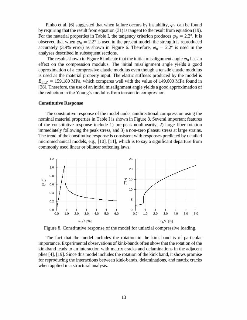
Constitutive Response
The constitutive response of the model under unidirectional compression using the
nominal material properties in Table I is shown in Figure 8. Several important features
of the constitutive response include 1) pre-peak nonlinearity, 2) large fiber rotation
immediately following the peak stress, and 3) a non-zero plateau stress at large strains.
The trend of the constitutive response is consistent with responses predicted by detailed
micromechanical models, e.g., [10], [11], which is to say a significant departure from
commonly used linear or bilinear softening laws.
Figure 8. Constitutive response of the model for uniaxial compressive loading.
The fact that the model includes the rotation in the kink-band is of particular
importance. Experimental observations of kink-bands often show that the rotation of the
kinkband leads to an interaction with matrix cracks and delaminations in the adjacent
plies [4], [19]. Since this model includes the rotation of the kink band, it shows promise
for reproducing the interactions between kink-bands, delaminations, and matrix cracks
when applied in a structural analysis.
[%] [%]
[ ]
0.0
0.2
0.4
0.6
0.8
1.0
1.2
0.0 1.0 2.0 3.0 4.0 5.0 6.0
0
5
10
15
20
25
0.0 1.0 2.0 3.0 4.0 5.0 6.0

14
Effect of Mode II Fracture Toughness and Friction
The matrix crack represented by the cohesive interface exhibits sliding with 𝜏N < 0
and so the Mode II fracture toughness, 𝐺𝐼𝐼𝑐, and the coefficient of friction, 𝜇, may play
important roles in the constitutive response of the model.
The constitutive responses of the model for three values of 𝐺𝐼𝐼𝑐 (𝐺𝐼𝐼𝑐, 0.5𝐺𝐼𝐼𝑐, and
10𝐺𝐼𝐼𝑐) are shown in Figure 9. In order to isolate the influence of 𝐺𝐼𝐼𝑐 from frictional
effects, the results shown are for 𝜇 = 0. When small values for 𝐺𝐼𝐼𝑐 are used, the
instability and vibration becomes more severe. The model shows comparatively less
sensitivity to larges values of 𝐺𝐼𝐼𝑐. In general, it is observed that 𝐺𝐼𝐼𝑐 influences the
steady-state plateau stress.
Figure 9. Effect of fracture toughness.
The coefficient of friction, 𝜇, used on the cohesive interface was varied to
investigate the sensitivity of the model to this parameter. No experimentally determined
value of 𝜇 was available. The longitudinal responses for three values of 𝜇 are shown in
Figure 10. The results indicate that the model is relatively insensitive to 𝜇. Therefore,
the assumed value has little bearing on the response characteristics and may not be
important for structural predictions for materials such as IM7-8552 that fail by shear
instability.
0.0
0.2
0.4
0.6
0.8
1.0
1.2
0.0 0.5 1.0 1.5 2.0 2.5 3.0
No
rma
lize
d s
tre
ss
Strain [%]
0.5x
10x
G2c
[%]

15
Figure 10. Effect of the coefficient of friction.
SUMMARY
A new mesoscale continuum damage mechanics (CDM) model has been proposed
to represent the constitutive response of plies subjected to longitudinal compression
loading. The model is formulated on the basis of the assumptions proposed in the LaRC
failure criteria and uses the deformation gradient decomposition approach to track the
rotation of the fibers through loading. The model is capable of representing several
features in the constitutive response, including the compressive stiffness, the strength,
the potential instability at kink-band onset, and the post-peak plateau stress. These
response characteristics agree with the trends predicted by detailed micromechanical
analyses. Since this model includes the rotation of the kink band, it shows promise for
reproducing the interactions between kink-bands, delaminations, and matrix cracks
when applied in a structural analysis.
REFERENCES
[1] Suemasu, H., Y. Naito, K. Gozu, and Y. Aoki. 2012. “Damage Initiation and Growth in Composite
Laminates during Open Hole Compression Tests,” Adv. Compos. Mater., 21(3):209-220.
[2] Hapke, J., F. Gehrig, N. Huber, K. Schulte, and E. T. Lilleodden. 2011. “Compressive Failure of UD-
CFRP Containing Void Defects: In Situ SEM Microanalysis,” Compos. Sci. Technol., 71(9):1242-
1249.
[3] Gutkin, R. and S. T. Pinho. 2015. “Combining Damage and Friction to Model Compressive Damage
Growth in Fibre-Reinforced Composites,” J. Compos. Mater., 49(20):2483–2495.
[%]
0.0
0.2
0.4
0.6
0.8
1.0
1.2
0.0 0.5 1.0 1.5 2.0 2.5
μ=0
μ=0.3
μ=0.6

16
[4] Zobeiry, N., R. Vaziri, and A. Poursartip. 2015. “Characterization of Strain-Softening Behavior and
Failure Mechanisms of Composites under Tension and Compression,” Compos. Part Appl. Sci.
Manuf., 68:29–41.
[5] Dávila, C. G. and P. P. Camanho. 2003. “Failure Criteria for FRP Laminates in Plane Stress,”
NASA/TM-2003-212663, NASA Langley Research Center.
[6] Pinho, S. T., C. G. Dávila, P. P. Camanho, L. Iannucci, and P. Robinson. 2005. “Failure Models and
Criteria for FRP under In-Plane or Three-Dimensional Stress States Including Shear Non-Linearity,”
NASA/TM-2005-213530, NASA Langley Research Center.
[7] Gutkin, R., S. T. Pinho, P. Robinson, and P. T. Curtis, “A Finite Fracture Mechanics Formulation to
Predict Fibre Kinking and Splitting in CFRP under Combined Longitudinal Compression and In-
Plane Shear,” Mech. Mater., 43(11):730–739.
[8] Catalanotti, G., P. P. Camanho, and A. T. Marques. 2013. “Three-Dimensional Failure Criteria for
Fiber-Reinforced Laminates,” Compos. Struct., 95:63–79.
[9] Camanho, P. P., A. Arteiro, A. R. Melro, G. Catalanotti, and M. Vogler. 2015. “Three-Dimensional
Invariant-Based Failure Criteria for Fibre-Reinforced Composites,” Int. J. Solids Struct., 55:92–107.
[10] Pimenta, S., R. Gutkin, S. T. Pinho, and P. Robinson. 2009. “A Micromechanical Model for Kink-
Band Formation: Part I — Experimental Study and Numerical Modelling,” Compos. Sci. Technol.,
69(7–8):948–955.
[11] Pimenta, S., R. Gutkin, S. T. Pinho, and P. Robinson. 2009. “A Micromechanical Model for Kink-
Band Formation: Part II—Analytical Modelling,” Compos. Sci. Technol., 69(7–8):956–964.
[12] Gutkin, R., S. T. Pinho, P. Robinson, and P. T. Curtis. 2010. “Micro-Mechanical Modelling of Shear-
Driven Fibre Compressive Failure and of Fibre Kinking for Failure Envelope Generation in CFRP
Laminates,” Compos. Sci. Technol., 70(8):1214–1222.
[13] Bai, X., M. A. Bessa, A. R. Melro, P. P. Camanho, L. Guo, and W. K. Liu. 2015. “High-Fidelity
Micro-Scale Modeling of the Thermo-Visco-Plastic Behavior of Carbon Fiber Polymer Matrix
Composites,” Compos. Struct., 134:132–141.
[14] Naya, F., C. González, C. S. Lopes, S. Van der Veen, and F. Pons. 2016. “Computational
Micromechanics of the Longitudinal Behaviour of Unidirectional Fibre Reinforced Polymers
Including Environmental Effects,” Compos. Sci. Technol., submitted.
[15] Maimí, P., P. P. Camanho, J.-A. Mayugo, and C. G. Dávila. 2006. “A Thermodynamically Consistent
Damage Model for Advanced Composites,” NASA/TM-2006-214282, NASA Langley Research
Center.
[16] Pinho, S. T., L. Iannucci, and P. Robinson. 2006. “Physically Based Failure Models and Criteria for
Laminated Fibre-Reinforced Composites with Emphasis on Fibre Kinking. Part II: FE
Implementation,” Compos. Part Appl. Sci. Manuf., 37(5):766–777.
[17] Camanho, P. P., M. A. Bessa, G. Catalanotti, M. Vogler, and R. Rolfes. 2013. “Modeling the Inelastic
Deformation and Fracture of Polymer Composites – Part II: Smeared Crack Model,” Mech. Mater.,
59:36–49.
[18] Iarve, E. V., K. Hoos, M. Braginsky, E. Zhou, and D. H. Mollenhauer. 2015. “Tensile and
Compressive Strength Prediction in Laminated Composites by Using Discrete Damage Modeling,”
presented at the AIAA/ASME/ASCE/AHS/ASC Structures, Structural Dynamics, and Materials
Conference, January 5-9, 2015.
[19] Sola, C., B. Castanié, L. Michel, F. Lachaud, A. Delabie, and E. Mermoz. 2016. “On the Role of
Kinking in the Bearing Failure of Composite Laminates,” Compos. Struct., 141:184–193.
[20] Schultheisz, C. R. and A. M. Waas. 1996. “Compressive Failure of Composites, Part I: Testing and
Micromechanical Theories,” Prog. Aerosp. Sci., 32(1):1–42.
[21] Argon, A. S. 1972 “Fracture of Composites,” Treatise Mater. Sci. Technol., 1:79–114.
[22] Guynn, E. G., O. O. Ochoa, and W. L. Bradley. 1992. “A Parametric Study of Variables That Affect
Fiber Microbuckling Initiation in Composite Laminates: Part 1-Analyses,” J. Compos. Mater.,
26(11):1594–1616.
[23] Budiansky, B. and N. A. Fleck. 1993. “Compressive Failure of Fibre Composites,” J. Mech. Phys.
Solids, 41(1):183–211.
[24] Jelf, P. M. and N. A. Fleck. 1992. “Compression Failure Mechanisms in Unidirectional Composites,”
J. Compos. Mater., 26(18):2706–2726.
[25] Basu, S., A. M. Waas, and D. R. Ambur. 2006. “Compressive Failure of Fiber Composites Under
Multi-Axial Loading,” J. Mech. Phys. Solids, 54:611–634.
[26] Basu, S., A. M. Waas, and D. R. Ambur. 2006. “A Macroscopic Model for Kink Banding Instabilities
in Fiber Composites,” J. Mech. Mater. Struct., 1(6):979–1000.

17
[27] Costa, S., R. Gutkin, and R. Olsson. 2016. “Finite Element Implementation of a Model for
Longitudinal Compressive Damage Growth with Friction,” presented at the ECCM17 - 17th
European Conference on Composite Materials, June 26-30, 2016.
[28] Leone Jr., F. A. 2015. “Deformation Gradient Tensor Decomposition for Representing Matrix Cracks
in Fiber-Reinforced Materials,” Compos. Part Appl. Sci. Manuf., 76:334–341.
[29] Gutkin, R., S. T. Pinho, P. Robinson, and P. T. Curtis. 2010. “On the Transition from Shear-Driven
Fibre Compressive Failure to Fibre Kinking in Notched CFRP Laminates under Longitudinal
Compression,” Compos. Sci. Technol., 70(8):1223–1231.
[30] Turon, A., P. P. Camanho, J. Costa, and C. G. Dávila. 2006. “A Damage Model for the Simulation
of Delamination in Advanced Composites under Variable-Mode Loading,” Mech. Mater.,
38(11):1072–1089.
[31] Jones, R. M. 1999. Mechanics of Composite Materials. NY: Taylor & Francis Group.
[32] Ramberg W. and W. R. Osgood. 1943. “Description of Stress–Strain Curves by Three Parameters,”
Technical Note No. 902, National Advisory Committee for Aeronautics.
[33] Puck, A. and H. Schürmann. 1998. “Failure Analysis of FRP Laminates by Means of Physically
Based Phenomenological Models,” Compos. Sci. Technol., 58(7):1045–1067.
[34] Alfano, G. and E. Sacco. 2006. “Combining Interface Damage and Friction in a Cohesive-Zone
Model,” Int. J. Numer. Methods Eng., 68(5):542–582.
[35] ABAQUS Online Documentation: Version 2016. Providence, RI: Dassault Systèmes Simulia
Corporation.
[36] Camanho, P. P., P. Maimí, and C. G. Dávila. 2007. “Prediction of Size Effects in Notched Laminates
using Continuum Damage Mechanics,” Compos. Sci. Technol., 67(13):2715–2727.
[37] Rose, C. A., C. G. Dávila, and F. A. Leone. 2013. “Analysis Methods for Progressive Damage of
Composite Structures,” NASA/TM–2013-218024, NASA Langley Research Center.
[38] HexPly® 8552 Epoxy Matrix Product Data. Hexcel, Feb., 2014.