Embed Size (px)
Citation preview
Paper-Based Electrochemical Sensing Platform with Integral Batteryand Electrochromic Read-OutHong Liu and Richard M. Crooks*
Department of Chemistry and Biochemistry, Center for Electrochemistry, and Center for Nano- and Molecular Science andTechnology, The University of Texas at Austin, 1 University Station, A5300, Austin, Texas 78712-0165, United States
*S Supporting Information
ABSTRACT: We report a battery-powered, microelectrochemicalsensing platform that reports its output using an electrochromicdisplay. The platform is fabricated based on paper fluidics and uses aPrussian blue spot electrodeposited on an indium-doped tin oxidethin film as the electrochromic indicator. The integrated metal/airbattery powers both the electrochemical sensor and the electro-chromic read-out, which are in electrical contact via a paper reservoir.The sample activates the battery and the presence of analyte in the sample initiates the color change of the Prussian blue spot.The entire system is assembled on the lab bench, without the need for cleanroom facilities. The applicability of the device topoint-of-care sensing is demonstrated by qualitative detection of 0.1 mM glucose and H2O2 in artificial urine samples.
We report a versatile microelectrochemical biosensingplatform that is based on paper fluidics and powered by
an integral metal/air battery. The battery powers both thesensing chemistry and an electrochromic display that providesan optical indication of the state of the system. The operatingvoltage of the device is controlled by the identity of the metalfoil used in the battery. The sensor is activated by application ofartificial urine (AU), which acts both as the matrix for theanalyte and the electrolyte for the battery. The entire system isassembled on the lab bench without the need for cleanroomfacilities. Taken together, these characteristics suggest theapproach described here is appropriate for point-of-care (POC)diagnosis and resource-limited sensing.1
Electrochemical methods are widely used for chemicalsensing due to their low cost, low power requirements, andsimplicity.2 Most such devices are based on electrolyticreactions and hence require a reader powered by either abattery or line voltage. However, a few self-powered sensorshave also been reported.3−5 The operational basis of the latterdevices is a galvanic reaction that is initiated by the presence ofan analyte which may or may not itself be redox-active. Forexample, we recently reported a self-powered sensor in which agalvanic reaction is triggered by the presence of non-electroactive trypsin.5
Recently, microfluidic paper analytical devices (μPADs) haveemerged as a promising solution to the need for low-costdiagnostic systems.6 The success of μPADs arises from twomain factors: low cost and visual (colorimetric) read-out.However, there is a problem with colorimetric detection: aunique chemistry must be devised and optimized for everyreaction. Electrochemical systems provide some relief for thissituation, because current replaces the visual read-out signal.This fact has driven the development of microfluidic paperelectrochemical devices (μPEDs), which now have thecapability of detecting multiple analytes via amperometry.7,8
However, the design principle for μPEDs that have beenreported thus far involves a disposable paper fluidic system thatis controlled and read out using a conventional potentiostat7,8
or commercial reader.9,10 Note, however, that in parallel withthe development of μPEDs, research in the field of energystorage has resulted in paper-based batteries.11,12
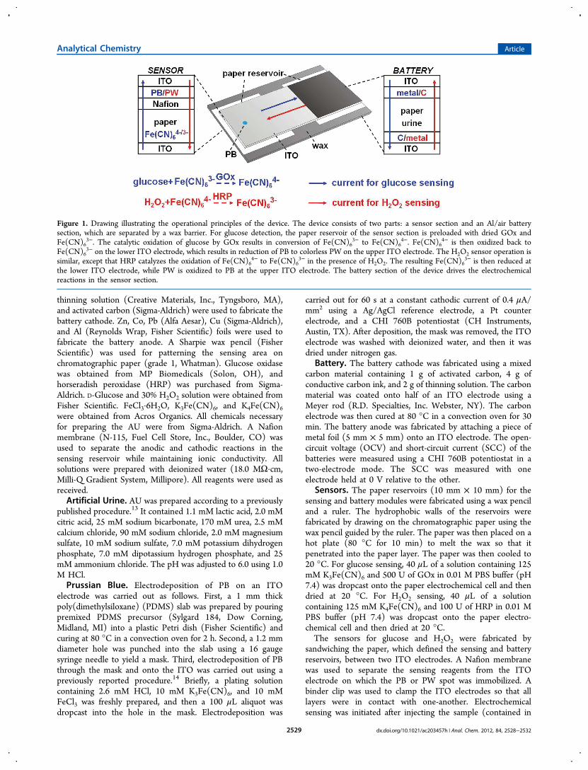
The principal advance reported in the present article is abroadly applicable means for fully integrating μPEDs with aninexpensive, on-board power source without giving up theconvenience of visual color-based read-out that has driven thefield of μPADs. The operational principles of the device areillustrated in Figure 1. The sensor is powered by a metal/airbattery that drives electrolytic reactions in a paper reservoirdefined by a wax frame. Electrical contact is made to the papervia a pair of transparent indium-doped tin oxide (ITO)electrodes. The paper is preloaded with a dried enzyme andFe(CN)6
3− or Fe(CN)64−. The analysis of glucose in AU is
carried out as follows. First, glucose in AU is applied to thepaper fluidic system, which directs the sample to the reactionzone. Second, glucose oxidase (GOx) present in the paperreaction zone catalyzes glucose oxidation with simultaneousreduction of Fe(CN)6
3− to Fe(CN)64−. This process activates
conversion of electrochromic Prussian blue (PB) on the ITOelectrode to colorless Prussian white (PW). As discussed later, asimilar approach is used to detect H2O2.
■ EXPERIMENTAL SECTIONChemicals and Materials. ITO electrodes were obtained
from Delta Technologies (Loveland, CO) and cut into 25 mm× 10 mm pieces using a glass cutter. Conductive carbon ink,
Received: December 24, 2011Accepted: February 3, 2012Published: February 22, 2012
Article
pubs.acs.org/ac
© 2012 American Chemical Society 2528 dx.doi.org/10.1021/ac203457h | Anal. Chem. 2012, 84, 2528−2532
thinning solution (Creative Materials, Inc., Tyngsboro, MA),and activated carbon (Sigma-Aldrich) were used to fabricate thebattery cathode. Zn, Co, Pb (Alfa Aesar), Cu (Sigma-Aldrich),and Al (Reynolds Wrap, Fisher Scientific) foils were used tofabricate the battery anode. A Sharpie wax pencil (FisherScientific) was used for patterning the sensing area onchromatographic paper (grade 1, Whatman). Glucose oxidasewas obtained from MP Biomedicals (Solon, OH), andhorseradish peroxidase (HRP) was purchased from Sigma-Aldrich. D-Glucose and 30% H2O2 solution were obtained fromFisher Scientific. FeCl3·6H2O, K3Fe(CN)6, and K4Fe(CN)6were obtained from Acros Organics. All chemicals necessaryfor preparing the AU were from Sigma-Aldrich. A Nafionmembrane (N-115, Fuel Cell Store, Inc., Boulder, CO) wasused to separate the anodic and cathodic reactions in thesensing reservoir while maintaining ionic conductivity. Allsolutions were prepared with deionized water (18.0 MΩ·cm,Milli-Q Gradient System, Millipore). All reagents were used asreceived.Artificial Urine. AU was prepared according to a previously
published procedure.13 It contained 1.1 mM lactic acid, 2.0 mMcitric acid, 25 mM sodium bicarbonate, 170 mM urea, 2.5 mMcalcium chloride, 90 mM sodium chloride, 2.0 mM magnesiumsulfate, 10 mM sodium sulfate, 7.0 mM potassium dihydrogenphosphate, 7.0 mM dipotassium hydrogen phosphate, and 25mM ammonium chloride. The pH was adjusted to 6.0 using 1.0M HCl.Prussian Blue. Electrodeposition of PB on an ITO
electrode was carried out as follows. First, a 1 mm thickpoly(dimethylsiloxane) (PDMS) slab was prepared by pouringpremixed PDMS precursor (Sylgard 184, Dow Corning,Midland, MI) into a plastic Petri dish (Fisher Scientific) andcuring at 80 °C in a convection oven for 2 h. Second, a 1.2 mmdiameter hole was punched into the slab using a 16 gaugesyringe needle to yield a mask. Third, electrodeposition of PBthrough the mask and onto the ITO was carried out using apreviously reported procedure.14 Briefly, a plating solutioncontaining 2.6 mM HCl, 10 mM K3Fe(CN)6, and 10 mMFeCl3 was freshly prepared, and then a 100 μL aliquot wasdropcast into the hole in the mask. Electrodeposition was
carried out for 60 s at a constant cathodic current of 0.4 μA/mm2 using a Ag/AgCl reference electrode, a Pt counterelectrode, and a CHI 760B potentiostat (CH Instruments,Austin, TX). After deposition, the mask was removed, the ITOelectrode was washed with deionized water, and then it wasdried under nitrogen gas.
Battery. The battery cathode was fabricated using a mixedcarbon material containing 1 g of activated carbon, 4 g ofconductive carbon ink, and 2 g of thinning solution. The carbonmaterial was coated onto half of an ITO electrode using aMeyer rod (R.D. Specialties, Inc. Webster, NY). The carbonelectrode was then cured at 80 °C in a convection oven for 30min. The battery anode was fabricated by attaching a piece ofmetal foil (5 mm × 5 mm) onto an ITO electrode. The open-circuit voltage (OCV) and short-circuit current (SCC) of thebatteries were measured using a CHI 760B potentiostat in atwo-electrode mode. The SCC was measured with oneelectrode held at 0 V relative to the other.
Sensors. The paper reservoirs (10 mm × 10 mm) for thesensing and battery modules were fabricated using a wax penciland a ruler. The hydrophobic walls of the reservoirs werefabricated by drawing on the chromatographic paper using thewax pencil guided by the ruler. The paper was then placed on ahot plate (80 °C for 10 min) to melt the wax so that itpenetrated into the paper layer. The paper was then cooled to20 °C. For glucose sensing, 40 μL of a solution containing 125mM K3Fe(CN)6 and 500 U of GOx in 0.01 M PBS buffer (pH7.4) was dropcast onto the paper electrochemical cell and thendried at 20 °C. For H2O2 sensing, 40 μL of a solutioncontaining 125 mM K4Fe(CN)6 and 100 U of HRP in 0.01 MPBS buffer (pH 7.4) was dropcast onto the paper electro-chemical cell and then dried at 20 °C.The sensors for glucose and H2O2 were fabricated by
sandwiching the paper, which defined the sensing and batteryreservoirs, between two ITO electrodes. A Nafion membranewas used to separate the sensing reagents from the ITOelectrode on which the PB or PW spot was immobilized. Abinder clip was used to clamp the ITO electrodes so that alllayers were in contact with one-another. Electrochemicalsensing was initiated after injecting the sample (contained in
Figure 1. Drawing illustrating the operational principles of the device. The device consists of two parts: a sensor section and an Al/air batterysection, which are separated by a wax barrier. For glucose detection, the paper reservoir of the sensor section is preloaded with dried GOx andFe(CN)6
3−. The catalytic oxidation of glucose by GOx results in conversion of Fe(CN)63− to Fe(CN)6
4−. Fe(CN)64− is then oxidized back to
Fe(CN)63− on the lower ITO electrode, which results in reduction of PB to colorless PW on the upper ITO electrode. The H2O2 sensor operation is
similar, except that HRP catalyzes the oxidation of Fe(CN)64− to Fe(CN)6
3− in the presence of H2O2. The resulting Fe(CN)63− is then reduced at
the lower ITO electrode, while PW is oxidized to PB at the upper ITO electrode. The battery section of the device drives the electrochemicalreactions in the sensor section.
Analytical Chemistry Article
dx.doi.org/10.1021/ac203457h | Anal. Chem. 2012, 84, 2528−25322529
AU) into the sensing reservoir. Upon injection of batteryelectrolyte, the battery was then activated to report the sensingresult.
■ RESULTS AND DISCUSSION
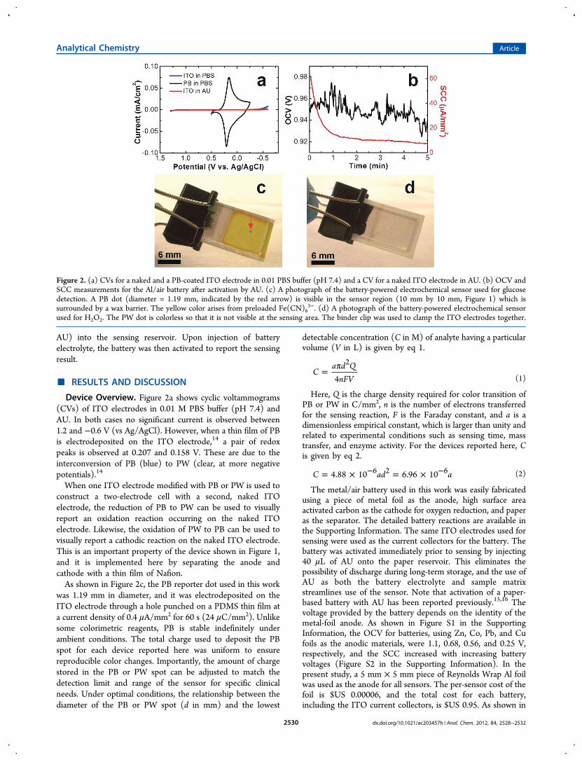
Device Overview. Figure 2a shows cyclic voltammograms(CVs) of ITO electrodes in 0.01 M PBS buffer (pH 7.4) andAU. In both cases no significant current is observed between1.2 and −0.6 V (vs Ag/AgCl). However, when a thin film of PBis electrodeposited on the ITO electrode,14 a pair of redoxpeaks is observed at 0.207 and 0.158 V. These are due to theinterconversion of PB (blue) to PW (clear, at more negativepotentials).14
When one ITO electrode modified with PB or PW is used toconstruct a two-electrode cell with a second, naked ITOelectrode, the reduction of PB to PW can be used to visuallyreport an oxidation reaction occurring on the naked ITOelectrode. Likewise, the oxidation of PW to PB can be used tovisually report a cathodic reaction on the naked ITO electrode.This is an important property of the device shown in Figure 1,and it is implemented here by separating the anode andcathode with a thin film of Nafion.As shown in Figure 2c, the PB reporter dot used in this work
was 1.19 mm in diameter, and it was electrodeposited on theITO electrode through a hole punched on a PDMS thin film ata current density of 0.4 μA/mm2 for 60 s (24 μC/mm2). Unlikesome colorimetric reagents, PB is stable indefinitely underambient conditions. The total charge used to deposit the PBspot for each device reported here was uniform to ensurereproducible color changes. Importantly, the amount of chargestored in the PB or PW spot can be adjusted to match thedetection limit and range of the sensor for specific clinicalneeds. Under optimal conditions, the relationship between thediameter of the PB or PW spot (d in mm) and the lowest
detectable concentration (C in M) of analyte having a particularvolume (V in L) is given by eq 1.
= πC
a d QnFV4
2
(1)
Here, Q is the charge density required for color transition ofPB or PW in C/mm2, n is the number of electrons transferredfor the sensing reaction, F is the Faraday constant, and a is adimensionless empirical constant, which is larger than unity andrelated to experimental conditions such as sensing time, masstransfer, and enzyme activity. For the devices reported here, Cis given by eq 2.
= × = ×− −C ad a4.88 10 6.96 106 2 6 (2)
The metal/air battery used in this work was easily fabricatedusing a piece of metal foil as the anode, high surface areaactivated carbon as the cathode for oxygen reduction, and paperas the separator. The detailed battery reactions are available inthe Supporting Information. The same ITO electrodes used forsensing were used as the current collectors for the battery. Thebattery was activated immediately prior to sensing by injecting40 μL of AU onto the paper reservoir. This eliminates thepossibility of discharge during long-term storage, and the use ofAU as both the battery electrolyte and sample matrixstreamlines use of the sensor. Note that activation of a paper-based battery with AU has been reported previously.15,16 Thevoltage provided by the battery depends on the identity of themetal-foil anode. As shown in Figure S1 in the SupportingInformation, the OCV for batteries, using Zn, Co, Pb, and Cufoils as the anodic materials, were 1.1, 0.68, 0.56, and 0.25 V,respectively, and the SCC increased with increasing batteryvoltages (Figure S2 in the Supporting Information). In thepresent study, a 5 mm × 5 mm piece of Reynolds Wrap Al foilwas used as the anode for all sensors. The per-sensor cost of thefoil is $US 0.00006, and the total cost for each battery,including the ITO current collectors, is $US 0.95. As shown in
Figure 2. (a) CVs for a naked and a PB-coated ITO electrode in 0.01 PBS buffer (pH 7.4) and a CV for a naked ITO electrode in AU. (b) OCV andSCC measurements for the Al/air battery after activation by AU. (c) A photograph of the battery-powered electrochemical sensor used for glucosedetection. A PB dot (diameter = 1.19 mm, indicated by the red arrow) is visible in the sensor region (10 mm by 10 mm, Figure 1) which issurrounded by a wax barrier. The yellow color arises from preloaded Fe(CN)6
3−. (d) A photograph of the battery-powered electrochemical sensorused for H2O2. The PW dot is colorless so that it is not visible at the sensing area. The binder clip was used to clamp the ITO electrodes together.
Analytical Chemistry Article
dx.doi.org/10.1021/ac203457h | Anal. Chem. 2012, 84, 2528−25322530
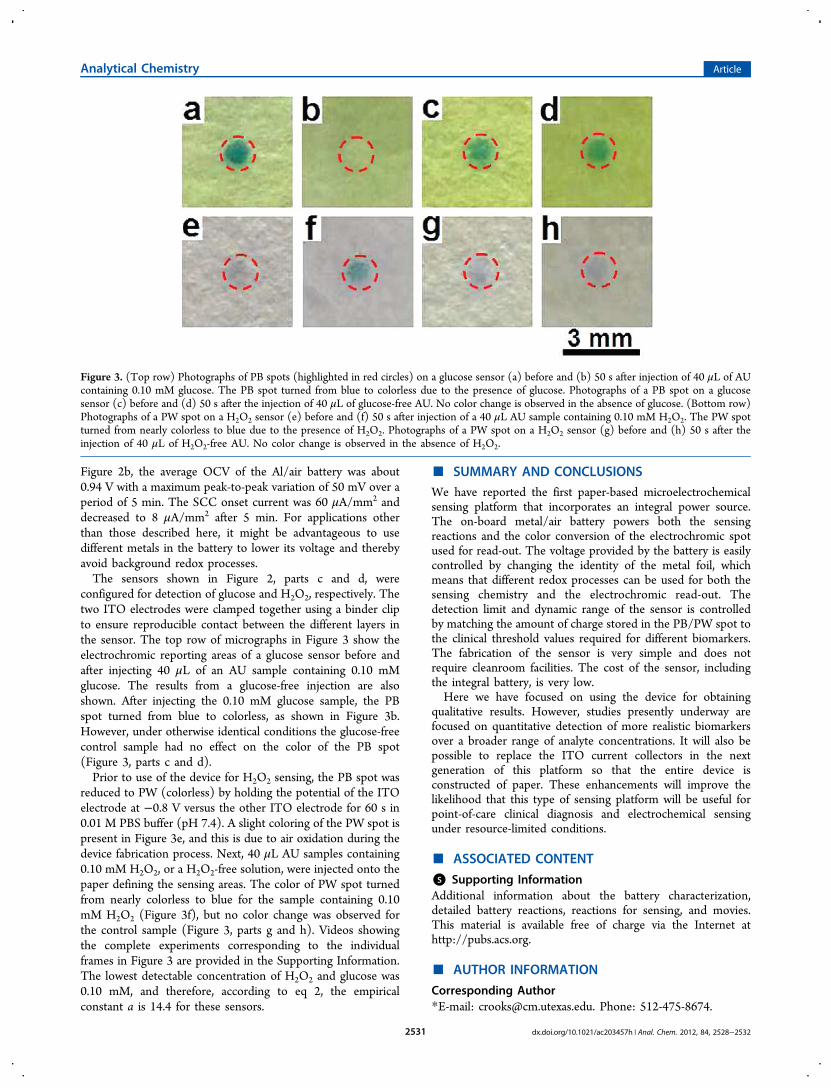
Figure 2b, the average OCV of the Al/air battery was about0.94 V with a maximum peak-to-peak variation of 50 mV over aperiod of 5 min. The SCC onset current was 60 μA/mm2 anddecreased to 8 μA/mm2 after 5 min. For applications otherthan those described here, it might be advantageous to usedifferent metals in the battery to lower its voltage and therebyavoid background redox processes.The sensors shown in Figure 2, parts c and d, were
configured for detection of glucose and H2O2, respectively. Thetwo ITO electrodes were clamped together using a binder clipto ensure reproducible contact between the different layers inthe sensor. The top row of micrographs in Figure 3 show theelectrochromic reporting areas of a glucose sensor before andafter injecting 40 μL of an AU sample containing 0.10 mMglucose. The results from a glucose-free injection are alsoshown. After injecting the 0.10 mM glucose sample, the PBspot turned from blue to colorless, as shown in Figure 3b.However, under otherwise identical conditions the glucose-freecontrol sample had no effect on the color of the PB spot(Figure 3, parts c and d).Prior to use of the device for H2O2 sensing, the PB spot was
reduced to PW (colorless) by holding the potential of the ITOelectrode at −0.8 V versus the other ITO electrode for 60 s in0.01 M PBS buffer (pH 7.4). A slight coloring of the PW spot ispresent in Figure 3e, and this is due to air oxidation during thedevice fabrication process. Next, 40 μL AU samples containing0.10 mM H2O2, or a H2O2-free solution, were injected onto thepaper defining the sensing areas. The color of PW spot turnedfrom nearly colorless to blue for the sample containing 0.10mM H2O2 (Figure 3f), but no color change was observed forthe control sample (Figure 3, parts g and h). Videos showingthe complete experiments corresponding to the individualframes in Figure 3 are provided in the Supporting Information.The lowest detectable concentration of H2O2 and glucose was0.10 mM, and therefore, according to eq 2, the empiricalconstant a is 14.4 for these sensors.
■ SUMMARY AND CONCLUSIONS
We have reported the first paper-based microelectrochemicalsensing platform that incorporates an integral power source.The on-board metal/air battery powers both the sensingreactions and the color conversion of the electrochromic spotused for read-out. The voltage provided by the battery is easilycontrolled by changing the identity of the metal foil, whichmeans that different redox processes can be used for both thesensing chemistry and the electrochromic read-out. Thedetection limit and dynamic range of the sensor is controlledby matching the amount of charge stored in the PB/PW spot tothe clinical threshold values required for different biomarkers.The fabrication of the sensor is very simple and does notrequire cleanroom facilities. The cost of the sensor, includingthe integral battery, is very low.Here we have focused on using the device for obtaining
qualitative results. However, studies presently underway arefocused on quantitative detection of more realistic biomarkersover a broader range of analyte concentrations. It will also bepossible to replace the ITO current collectors in the nextgeneration of this platform so that the entire device isconstructed of paper. These enhancements will improve thelikelihood that this type of sensing platform will be useful forpoint-of-care clinical diagnosis and electrochemical sensingunder resource-limited conditions.
■ ASSOCIATED CONTENT
*S Supporting InformationAdditional information about the battery characterization,detailed battery reactions, reactions for sensing, and movies.This material is available free of charge via the Internet athttp://pubs.acs.org.
■ AUTHOR INFORMATION
Corresponding Author*E-mail: [email protected]. Phone: 512-475-8674.
Figure 3. (Top row) Photographs of PB spots (highlighted in red circles) on a glucose sensor (a) before and (b) 50 s after injection of 40 μL of AUcontaining 0.10 mM glucose. The PB spot turned from blue to colorless due to the presence of glucose. Photographs of a PB spot on a glucosesensor (c) before and (d) 50 s after the injection of 40 μL of glucose-free AU. No color change is observed in the absence of glucose. (Bottom row)Photographs of a PW spot on a H2O2 sensor (e) before and (f) 50 s after injection of a 40 μL AU sample containing 0.10 mM H2O2. The PW spotturned from nearly colorless to blue due to the presence of H2O2. Photographs of a PW spot on a H2O2 sensor (g) before and (h) 50 s after theinjection of 40 μL of H2O2-free AU. No color change is observed in the absence of H2O2.
Analytical Chemistry Article
dx.doi.org/10.1021/ac203457h | Anal. Chem. 2012, 84, 2528−25322531
NotesThe authors declare no competing financial interest.
■ ACKNOWLEDGMENTSWe gratefully acknowledge support from the ChemicalSciences, Geosciences, and Biosciences Division, Office ofBasic Energy Sciences, Office of Science, U.S. Department ofEnergy (contract no. DE-FG02-06ER15758). We also thankthe U.S. Army Research Office (Grant No. W911NF-07-1-0330) and the U.S. Defense Threat Reduction Agency forfinancial support. The Robert A. Welch Foundation providessustained support for our research (Grants F-0032 and H−F-0037).
■ REFERENCES(1) Gubala, V.; Harris, L. F.; Ricco, A. J.; Tan, M. X.; Williams, D. E.Anal. Chem. 2012, 84, 487−515.(2) Wang, J. Trends Anal. Chem. 2002, 21, 226−232.(3) Katz, E.; Buckmann, A. F.; Willner, I. J. Am. Chem. Soc. 2001, 123,10752−10753.(4) Germain, M. N.; Arechederra, R. L.; Minteer, S. D. J. Am. Chem.Soc. 2008, 130, 15272−15273.(5) Zaccheo, B. A.; Crooks, R. M. Anal. Chem. 2011, 83, 1185−1188.(6) Martinez, A. W.; Phillips, S. T.; Whitesides, G. M.; Carrilho, E.Anal. Chem. 2010, 82, 3−10.(7) Dungchai, W.; Chailapakul, O.; Henry, C. S. Anal. Chem. 2009,81, 5821−5826.(8) Nie, Z. H.; Nijhuis, C. A.; Gong, J. L.; Chen, X.; Kumachev, A.;Martinez, A. W.; Narovlyansky, M.; Whitesides, G. M. Lab Chip 2010,10, 477−483.(9) Nie, Z. H.; Deiss, F.; Liu, X. Y.; Akbulut, O.; Whitesides, G. M.Lab Chip 2010, 10, 3163−3169.(10) Xiang, Y.; Lu, Y. Nat. Chem. 2011, 3, 697−703.(11) Hu, L. B.; Choi, J. W.; Yang, Y.; Jeong, S.; La Mantia, F.; Cui, L.F.; Cui, Y. Proc. Natl. Acad. Sci. U.S.A. 2009, 106, 21490−21494.(12) Hilder, M.; Winther-Jensen, B.; Clark, N. B. J. Power Sources2009, 194, 1135−1141.(13) Martinez, A. W.; Phillips, S. T.; Whitesides, G. M. Proc. Natl.Acad. Sci. U.S.A. 2008, 105, 19606−19611.(14) Itaya, K.; Ataka, T.; Toshima, S. J. Am. Chem. Soc. 1982, 104,4767−4772.(15) Lee, K. B. J. Micromech. Microeng. 2005, 15, S210−S214.(16) Lee, K. B. J. Micromech. Microeng. 2006, 16, 2312−2317.
Analytical Chemistry Article
dx.doi.org/10.1021/ac203457h | Anal. Chem. 2012, 84, 2528−25322532