Embed Size (px)
Citation preview
PANEL ANTENNASWITH ONLY HIGH BAND ARRAYS
54 | April 2015

HighBand
April 2015 | 55
Ultra-wideband antennas designed to handle 2G, 3G networks and MIMO configurations for LTE on 1.8 / 2.1 / 2.6 networks.

(2x) 1695-2180 / 2490-2690 MHz
61776006177600A 6177600G 6177600DG
Twin Dual Band | Panel Antenna | (2x) XX-Pol | 65° / 65° | 17.0 / 17.5 dBi | Variable Tilt
• Twin dual band antenna, dual polarisation, 8 connectors • Independent tilt on each band 0-12° / 0-12°• Ultra compact Quadband system for MIMO applications • MET and RET versions, AISG1.1 or 3GPP/AISG2.0 • Fully internal RET control based on our patented technologies (field replaceable)
Several patents pending regarding this product. Quoted performance parameters are provided to offer typical, peak or range values only and may vary as a result of normal testing, manufacturing and operational conditions. Extreme operational conditions and/or stress on structural supports is beyond our control. Such conditions may result in damage to this product. Improvements to products may be made without notice.
Ordering Options Model Number
Manual Electrical Tilt 6177600
Remote Electrical Tilt AISG1.1 6177600A
Remote Electrical Tilt 3GPP/AISG2.0 with an MDCU RET Actuator 6177600G
Remote Electrical Tilt 3GPP/AISG2.0 with an MDDU RET Actuator 6177600DG
Access Ports Description (Connectors)
This antenna is built with two identical Dual Band Antennas, housed side-by-side in the same shroud. The antenna has 8 colour-coded connectors located at the bottom face. See image on the following page.
Wide Band 1695-2180 MHz Ports (2x) 4.3-10 Female Long Neck
LTE 2600 2490-2690 MHz Ports (2x) 4.3-10 Female Long Neck
Electrical Characteristics B1-B2 Y1-Y2
Frequency Bands (MHz) 1800 2100 2600
Gain (dBi)Tilt 0°Tilt Mid ValueTilt Max Value
16.816.816.8
17.117.117.0
17.517.517.2
Input Impedance 50Ω 50Ω
VSWR < 1.5 < 1.5
Polarisation ±45° ±45°
Horizontal Beamwidth (-3 dB) 65° 63° 61°
Vertical Beamwidth (-3 dB) 7.0° 6.4° 5.2°
Electrical Downtilt Range 0-12° 0-12°
Inter/Intra Band Isolation > 30 dB, > 28 dB from 0° to 2° tilt > 30 dB, > 28 dB from 0° to 2° tilt
Upper Sidelobe Rejection(20° sector above main beam)
18 dB Typical 18 dB Typical
Front-to-Back Ratio
@ 180°@ 180° ±30°
> 30 dB> 25 dB
> 30 dB> 25 dB
Maximum Power (Per Port) 200 W 200 W
Intermodulation3rd Order for 2x20W Carriers
< -110 dBm < -110 dBm
Electrical Downtilt Control
Electrical downtilt for each band can be controlled separately. Tilt indicator(s) are covered by removable transparent cap(s).
Manual Electrical Tilt (MET) Control
A coloured knob at the end of the tilt indicator allows change of the tilt without need of a tool. The knob colour is identical to the corresponding connector ring colour. To access the knob, remove the cap by turning it counter-clockwise. It is re-installed by opposite rotation. Do not remove the transparent cap(s) from the antenna.
Remote Electrical Tilt (RET) Control
The remote control of the electrical tilt is managed by a Multi-Device Control Unit (MDCU) or a Multi-Device Dual Unit (MDDU) inserted in the bottom of the antenna. A single actuator individually controls the tilt of each band (no need for daisy chain cables between the bands). This module does not add any additional length to the antenna. For RET control, the transparent caps must be in place and locked. The tilt angle indicators always remain visible and the antenna still has manual tilt control (manual override).
RET-Ready antennas are delivered with the RET Actuator (MDCU or MDDU) already installed and pre-commissioned with all antenna parameters. Every RET device is factory configured and calibrated so the antenna is ready to be used once delivered to the site which means that there is no need for further installation of RET devices or for programming their configuration or for running a calibration process.
RET-Ready Actuator (one per antenna)
Multi-Device Control Unit (MCDU)
The MDCU is an electronic module that allows the remote control of the electrical downtilt (RET) in Amphenol antennas with factory embedded motors. Refer to ordering options.
Multi-Device Dual Unit (MDDU)
The MDDU allows two separate RET Controllers to independently drive the RETs in antennas with factory embedded motors (for antenna sharing or two technologies). Refer to ordering options.
Environmental
Operating Temperature Range -40° C to +60° C
Environmental ETS 300 019
RoHS Compliant Yes
B1
Y1
B2
Y2
56 | April 2015

Mechanical Characteristics
Dimensions (Height x Width x Depth) 1390 x 265 x 114 mm
Weight (Excluding Mounting Accessories) 17 kg
Shroud Outdoor Fibreglass, Grey RAL7035
Wind Speed Operational: 160 km/hr Survival: 200 km/h
Wind Load at 150 km/h Frontal: 420 N Lateral: 270 N Rear: 455 N
Mounting Kit Options Part Number Weight
All mounting bracket kits are ordered separately unless otherwise indicated. Select from the options listed below.
Brackets for pole 48 to 115 mm 0900181/00 3.4 kg
Brackets for pole 70 to 150 mm 0900182/00 3.9 kg
Kit to add mechanical tilt to above brackets 0900396/00 2.3 kg
(2x) 1695-2180 / 2490-2690 MHz
61776006177600A 6177600G 6177600DG
Twin Dual Band | Panel Antenna | (2x) XX-Pol | 65° / 65° | 17.0 / 17.5 dBi | Variable Tilt
Several patents pending regarding this product. Quoted performance parameters are provided to offer typical, peak or range values only and may vary as a result of normal testing, manufacturing and operational conditions. Extreme operational conditions and/or stress on structural supports is beyond our control. Such conditions may result in damage to this product. Improvements to products may be made without notice.
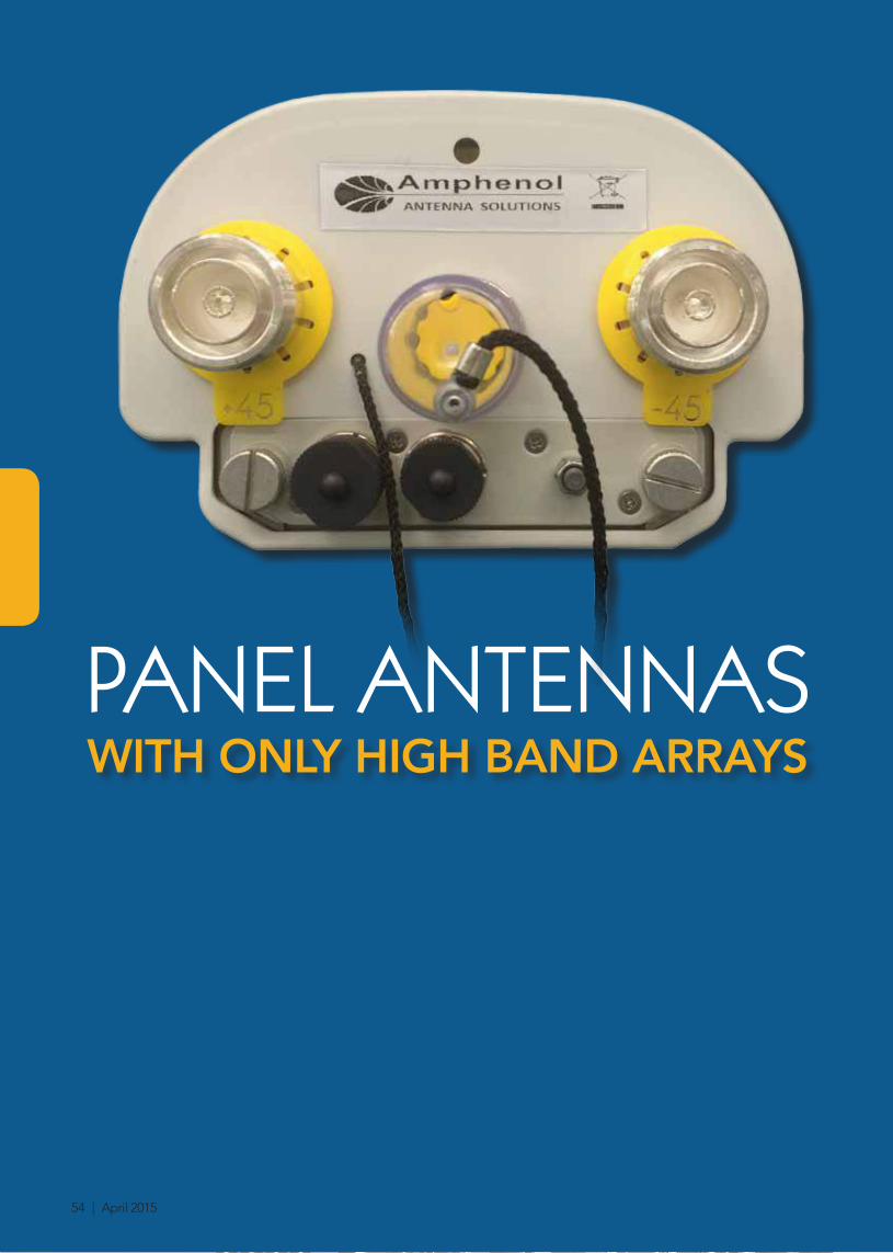
Location of the MDCU or MDDU for RET Control
Tilt indicators covered by transparent caps. Manual adjustment is accessed by removing the caps. Knob colours are the same as the connectors.
Bottom View of Antenna
Dimensions (in mm)
In order to operate RET control, the transparent caps covering the tilt adjustment indicators must be engaged and locked. Do not cut them from the antenna.
Always attach the antenna by the two mounting points.
Do no install the antenna with the connectors facing upward.
Installation
Packaging
Carton Box 1.61 x 0.365 x 0.23 m 0.135 m3 27 kg Includes 0900181/00 Kit
April 2015 | 57

(2x) 1710-2690 MHz
61771006177100A 6177100G
Twin Single Band | Panel Antenna | (2x) X-Pol | 65° | 18.0 dBi | Variable Tilt
• Twin single band antenna, dual polarisation, 4 connectors • Wide range of electrical tilt, variable 0-12° on each antenna
• MET and RET versions, AISG1.1 or 3GPP/AISG2.0 • Fully internal RET control based on our patented technologies
Several patents pending regarding this product. Quoted performance parameters are provided to offer typical, peak or range values only and may vary as a result of normal testing, manufacturing and operational conditions. Extreme operational conditions and/or stress on structural supports is beyond our control. Such conditions may result in damage to this product. Improvements to products may be made without notice.
Ordering Options Model Number
Manual Electrical Tilt 6177100
Remote Electrical Tilt AISG1.1 6177100A
Remote Electrical Tilt 3GPP/AISG2.0 with an MDCU RET Actuator 6177100G
Access Ports Description (Connectors)
The antenna has 4 connectors located at the bottom face. See image on the following page.
Ultra Wide Band 1710-2690 MHz LEFT Ports (2x) 7/16-DIN Female Long Neck
Ultra Wide Band 1710-2690 MHz RIGHT Ports (2x) 7/16-DIN Female Long Neck
Electrical Characteristics (General)
The antenna contains two radiating arrays housed in a single mechanical structure.
Isolation Between Arrays > 30 dB
Electrical Characteristics
Frequency Bands 1710...1880...2170...2690 MHz
Gain 16.9...17.2...17.6...18.0 dBi
Input Impedance 50Ω
VSWR < 1.5
Polarisation ±45°
Horizontal Beamwidth (-3 dB) 65°
Vertical Beamwidth (-3 dB) 6°
Electrical Downtilt Range 0-12°
Isolation Between Ports > 30 dB
Upper Sidelobe Rejection(20° sector above main beam)
> 18 dB
Null Fill (First Null Below Main Beam) < 18 dB Typical
Front-to-Back Ratio > 30 dB
Maximum Power (Per Port) 160 W
Intermodulation3rd Order for 2x20W Carriers
< -153 dBc
Electrical Downtilt Control
Electrical downtilt for each band can be controlled separately. Tilt indicator(s) are covered by removable transparent cap(s).
Manual Electrical Tilt (MET) Control
A coloured knob at the end of the tilt indicator allows change of the tilt without need of a tool. The knob colour is identical to the corresponding connector ring colour. To access the knob, remove the cap by turning it counter-clockwise. It is re-installed by opposite rotation. Do not remove the transparent cap(s) from the antenna.
Remote Electrical Tilt (RET) Control
The remote control of the electrical tilt is managed by a Multi-Device Control Unit (MDCU) inserted in the bottom of the antenna. A single actuator individually controls the tilt of each band (no need for daisy chain cables between the bands). This module does not add any additional length to the antenna. For RET control, the transparent caps must be in place and locked. The tilt angle indicators always remain visible and the antenna still has manual tilt control (manual override).
RET Module Part Number(one per antenna)
MDCU-A0000 for AISG1.1 protocol (one unit included in 6177100A)
MDCU-G0000 for 3GPP/AISG2.0 protocol (one unit included in 6177100G)
Environmental
Operating Temperature Range -40° C to +60° C
Environmental ETS 300 019
RoHS Compliant Yes
58 | April 2015

Mechanical Characteristics
Dimensions (Height x Width x Depth) 1394 x 265 x 114 mm
Weight (Excluding Mounting Accessories) 13 kg
Shroud Outdoor Plastic, Grey RAL7035
Wind Speed Operational: 160 km/hr Survival: 200 km/h
Wind Load(EN1991-4-1)
at 150 km/h Frontal: 420 N Lateral: 270 N Rear: 455 N
at 160 km/h Frontal: 478 N Lateral: 307 N Rear: 518 N
Mounting Kit Options Part Number Weight
All mounting bracket kits are ordered separately unless otherwise indicated. Select from the options listed below.
Brackets for pole 48 to 115 mm 0900181/00 3.4 kg
Brackets for pole 70 to 150 mm 0900182/00 3.9 kg
Kit to add mechanical tilt to above brackets 0900396/00 2.3 kg
Wall mounting bracket with azimuth pan 0900183/00 1.6 kg
Wall mounting brackets with mechanical tilt and azimuth pan
0900885/00 3.3 kg
(2x) 1710-2690 MHz
61771006177100A 6177100G
Twin Single Band | Panel Antenna | (2x) X-Pol | 65° | 18.0 dBi | Variable Tilt
Several patents pending regarding this product. Quoted performance parameters are provided to offer typical, peak or range values only and may vary as a result of normal testing, manufacturing and operational conditions. Extreme operational conditions and/or stress on structural supports is beyond our control. Such conditions may result in damage to this product. Improvements to products may be made without notice.
1394
1127
,5
265 114
Location of the MDCU for RET Control
Tilt indicators covered by transparent caps. Manual adjustment is accessed by removing the caps. Knob colours are the same as the connectors.
Bottom View of Antenna Dimensions (in mm)
In order to operate RET control, the transparent caps covering the tilt adjustment indicators must be engaged and locked. Do not cut them from the antenna.
Always attach the antenna by the two mounting points.
Do no install the antenna with the connectors facing upward.
Installation
Y1 1710-2690 MHz
Y2 1710-2690 MHz
Packaging
Carton Box 1.61 x 0.365 x 0.23 m 0.135 m3 23 kg Includes 0900181/00 Kit
April 2015 | 59

(3x) 1710-2690 MHz
61774006177400A 6177400G
Triple Band | Panel Antenna | (3x) X-Pol | 65° | 18.0 dBi | Variable Tilt
• Triple Ultra Wideband antenna, dual polarisation, 6 connectors • Wide range of electrical tilt, variable 0-12° on each antenna
• MET and RET versions, AISG1.1 or 3GPP/AISG2.0 • Fully internal RET control based on our patented technologies
Several patents pending regarding this product. Quoted performance parameters are provided to offer typical, peak or range values only and may vary as a result of normal testing, manufacturing and operational conditions. Extreme operational conditions and/or stress on structural supports is beyond our control. Such conditions may result in damage to this product. Improvements to products may be made without notice.
Ordering Options Model Number
Manual Electrical Tilt 6177400
Remote Electrical Tilt AISG1.1 6177400A
Remote Electrical Tilt 3GPP/AISG2.0 with an MDCU RET Actuator 6177400G
Access Ports Description (Connectors)
The antenna has 6 connectors located at the bottom face. See image on the following page.
Ultra Wide Band 1710-2690 MHz LEFT Ports (2x) 7/16-DIN Female Long Neck
Ultra Wide Band 1710-2690 MHz CENTER Ports (2x) 7/16-DIN Female Long Neck
Ultra Wide Band 1710-2690 MHz RIGHT Ports (2x) 7/16-DIN Female Long Neck
Electrical Characteristics (General)
The antenna contains three radiating arrays housed in a single mechanical structure.
Isolation Between Arrays > 30 dB
Electrical Characteristics
Frequency Bands 1710...1880...2170...2690 MHz
Gain 16.9...17.2...17.6...18.3 dBi
Input Impedance 50Ω
VSWR < 1.5
Polarisation ±45°
Horizontal Beamwidth (-3 dB) 65°
Vertical Beamwidth (-3 dB) 6°
Electrical Downtilt Range 0-12°
Isolation Between Ports > 28 dB
Upper Sidelobe Rejection(20° sector above main beam)
> 18 dB
Null Fill (First Null Below Main Beam) < 18 dB Typical
Front-to-Back Ratio > 30 dB
Maximum Power (Per Port) 160 W
Intermodulation3rd Order for 2x20W Carriers
< -153 dBc
Electrical Downtilt Control
Electrical downtilt for each band can be controlled separately. Tilt indicator(s) are covered by removable transparent cap(s).
Manual Electrical Tilt (MET) Control
A coloured knob at the end of the tilt indicator allows change of the tilt without need of a tool. The knob colour is identical to the corresponding connector ring colour. To access the knob, remove the cap by turning it counter-clockwise. It is re-installed by opposite rotation. Do not remove the transparent cap(s) from the antenna.
Remote Electrical Tilt (RET) Control
The remote control of the electrical tilt is managed by a Multi-Device Control Unit (MDCU) inserted in the bottom of the antenna. A single actuator individually controls the tilt of each band (no need for daisy chain cables between the bands). This module does not add any additional length to the antenna. For RET control, the transparent caps must be in place and locked. The tilt angle indicators always remain visible and the antenna still has manual tilt control (manual override).
RET Module Part Number(one per antenna)
MDCU-A0000 for AISG1.1 protocol (one unit included in 6177400A)
MDCU-G0000 for 3GPP/AISG2.0 protocol (one unit included in 6177400G)
Environmental
Operating Temperature Range -40° C to +60° C
Environmental ETS 300 019
RoHS Compliant Yes
60 | April 2015

Mechanical Characteristics
Dimensions (Height x Width x Depth) 1394 x 392 x 114
Weight (Excluding Mounting Accessories) 22.5 kg
Shroud Outdoor Plastic, Grey RAL7035
Wind Speed Operational: 160 km/hr Survival: 200 km/h
Wind Load(EN1991-4-1)
at 150 km/h Frontal: 625 N Lateral: 250 N Rear: 678 N
at 160 km/h Frontal: 712 N Lateral: 285 N Rear: 771 N
Mounting Kit Options Part Number Weight
All mounting bracket kits are ordered separately unless otherwise indicated. Select from the options listed below.
Brackets for pole 48 to 115 mm 0900181/00 3.4 kg
Brackets for pole 70 to 150 mm 0900182/00 3.9 kg
Kit to add mechanical tilt to above brackets 0900396/00 2.3 kg
Wall mounting bracket with azimuth pan 0900183/00 1.6 kg
Wall mounting brackets with mechanical tilt and azimuth pan
0900885/00 3.3 kg
(3x) 1710-2690 MHz
61774006177400A 6177400G
Triple Band | Panel Antenna | (3x) X-Pol | 65° | 18.0 dBi | Variable Tilt
Several patents pending regarding this product. Quoted performance parameters are provided to offer typical, peak or range values only and may vary as a result of normal testing, manufacturing and operational conditions. Extreme operational conditions and/or stress on structural supports is beyond our control. Such conditions may result in damage to this product. Improvements to products may be made without notice.
1394
1127
,5
392 114 Location of the MDCU for RET Control
Tilt indicators covered by transparent caps. Manual adjustment is accessed by removing the caps. Knob colours are the same as the connectors.
Bottom View of Antenna Dimensions (in mm)
In order to operate RET control, the transparent caps covering the tilt adjustment indicators must be engaged and locked. Do not cut them from the antenna.
Always attach the antenna by the two mounting points.
Do no install the antenna with the connectors facing upward.
Installation
Y1 1710-2690 MHz
Y2 1710-2690 MHz
Y3 1710-2690 MHz
Packaging
Carton Box 1.61 x 0.35 x 0.25 m 0.13 m3 | 28 kg
April 2015 | 61

1710-2690 MHz
61761006176100A 6176100G
Single Band | Panel Antenna | X-Pol | 65° | 18.3 dBi | Variable Tilt
• Ultra wide band antenna, dual polarisation, 2 connectors • Wide range of electrical tilt, variable 0-12°
• MET and RET versions, AISG1.1 or 3GPP/AISG2.0 • RET module fully inserted inside the antenna (field replaceable)
Several patents pending regarding this product. Quoted performance parameters are provided to offer typical, peak or range values only and may vary as a result of normal testing, manufacturing and operational conditions. Extreme operational conditions and/or stress on structural supports is beyond our control. Such conditions may result in damage to this product. Improvements to products may be made without notice.
Ordering Options Model Number
Manual Electrical Tilt 6176100
Remote Electrical Tilt AISG1.1 6176100A
Remote Electrical Tilt 3GPP/AISG2.0 with an MDCU RET Actuator 6176100G
Access Ports Description (Connectors)
The antenna has 2 colour-coded connectors located at the bottom face. See image on the following page.
YELLOW Rings Ultra Wide Band 1710-2690 MHz Ports (2x) 7/16-DIN Female Long Neck
Electrical Characteristics
Frequency Bands 1710...1880...2170...2690 MHz
Gain 16.9...17.2...17.6...18.3 dBi
Input Impedance 50Ω
VSWR < 1.5
Polarisation ±45°
Horizontal Beamwidth (-3 dB) 65°
Vertical Beamwidth (-3 dB) 6°
Electrical Downtilt Range 0-12°
Isolation Between Ports > 30 dB
Upper Sidelobe Rejection(20° sector above main beam)
> 18 dB
Null Fill (First Null Below Main Beam) < 18 dB Typical
Front-to-Back Ratio > 30 dB
Maximum Power (Per Port) 160 W
Intermodulation3rd Order for 2x20W Carriers
< -153 dBc
Electrical Downtilt Control
The tilt indicator is covered by a removable transparent cap.
Manual Electrical Tilt (MET) Control
A coloured knob at the end of the tilt indicator allows change of the tilt without need of a tool. The knob colour is identical to the connector colour as defined above. To access the knob, remove the cap by turning it counter-clockwise. It is re-installed by opposite rotation. Do not remove the transparent cap from the antenna.
Remote Electrical Tilt (RET) Control The remote control of the electrical tilt is managed by a Multi-Device Control Unit (MDCU) inserted in the bottom
of the antenna. This module does not add any additional length to the antenna. For RET control, the transparent cap must be in place and locked. The tilt angle indicator always remains visible and the antenna still has manual tilt control (manual override).
RET Module Part Number(one per antenna)
MDCU-A0000 for AISG1.1 protocol (one unit included in 6176100A)
MDCU-G0000 for 3GPP/AISG2.0 protocol (one unit included in 6176100G)
Environmental
Operating Temperature Range -40° C to +60° C
Environmental ETS 300 019
RoHS Compliant Yes
62 | April 2015
Mechanical Characteristics
Dimensions (Height x Width x Depth) 1390 x 170 x 100 mm
Weight (Excluding Mounting Accessories) 7 kg
Shroud Outdoor Plastic, Grey RAL7035
Wind Speed Operational: 160 km/hr Survival: 200 km/h
Wind Load at 160 km/h Frontal: 288 N Side: 167 N
Mounting Kit Options Part Number Weight
All mounting bracket kits are ordered separately unless otherwise indicated. Select from the options listed below.
Brackets for pole 48 to 115 mm 0900181/00 3.4 kg
Kit to add mechanical tilt to above brackets 0900188/00 1.5 kg
1710-2690 MHz
61761006176100A 6176100G
Single Band | Panel Antenna | X-Pol | 65° | 18.3 dBi | Variable Tilt
Several patents pending regarding this product. Quoted performance parameters are provided to offer typical, peak or range values only and may vary as a result of normal testing, manufacturing and operational conditions. Extreme operational conditions and/or stress on structural supports is beyond our control. Such conditions may result in damage to this product. Improvements to products may be made without notice.
77
100
139
0
170
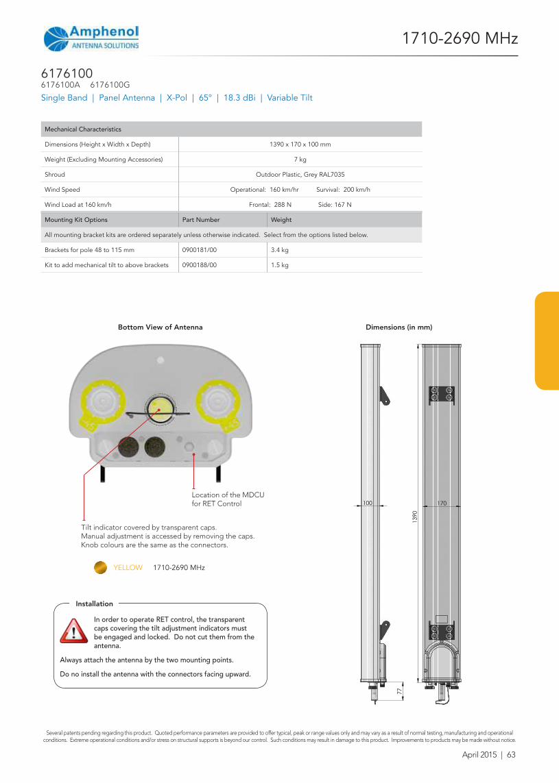
Location of the MDCU for RET Control
Tilt indicator covered by transparent caps. Manual adjustment is accessed by removing the caps. Knob colours are the same as the connectors.
Bottom View of Antenna Dimensions (in mm)
In order to operate RET control, the transparent caps covering the tilt adjustment indicators must be engaged and locked. Do not cut them from the antenna.
Always attach the antenna by the two mounting points.
Do no install the antenna with the connectors facing upward.
Installation
YELLOW 1710-2690 MHz
April 2015 | 63