Embed Size (px)
Citation preview

Amphenol
162GB Series Miniature Bayonet Lock Connectors
Amphenol
CONTENTS Pages • Introduction to 162GB Crimp Connectors 2 • Audio Applications 2 • Cable Assembly Facilities at Amphenol Ltd 2 • MIL-C-26482 Qualification Approval Tests 3-4 • DEF 5325 Qualification Approval Tests • Table of Shell Styles 5 • Insert Availability and Voltage Ratings 6-7 • How to Order 162GB Crimp Connectors 8 • Box Mounting Receptacles 9-10 • Single Hole Fixing Receptacles 11-12 • Cable Mounting Receptacles 13-14 • Plugs 15-16 • Plugs with optional Coupling Rings 17-18 • Cable Accessories 19 • Cables to DEF 10 20 • Accessories • Dust Caps 21-28 • AIA Backshells – Interconnection Accessories 29-31 • Interconnection Accessories Installation Procedure 32-33 • Interconnection Accessories Shield Term Process 34 • Key/keyway Orientations 35 • Insert Orientations 36 • 162GB Crimp Assembly Instructions 37-42

2
Development and manufacture of 162GB miniature bayonet lock connectors has been closely coordinated with the solder version. The entire programme has been carried out at Amphenol’s Whitstable Plant. The precision machinery and measurement control processes used for the production of 162GB crimp connectors are the same as those used to produce 62GB solder connectors. Full intermountability and intermateability are absolutely guaranteed. 162GB Series crimp connectors share many of the features of 62GB solder connectors. Coupling is achieved with a triple-track bayonet locking system which gives positive alignment on all shell sizes. When connector halves are fully mated there is a definite click. Inspection holes in the coupling ring will then reveal the bayonet pins on the receptacle which are clearly marked in yellow. The Amphenol design means simplified removal of coupling rings for servicing or replacement as they are front demountable. In addition there is a rough grip heavy duty style for arduous conditions and a lever coupling ring which allows extremely close mounting of connectors. The method of sealing is the same as for 62GB connectors; using peripheral seals on the rubber inserts and sealing the mating shells with a square section gasket. Wire sealing is by multiple risers in the rear grommet. Derating
Connectors must be derated under the following operating temperatures: 1. At elevated temperatures, the current ratings are
reduced as show in the table on page 10. 2. At high altitudes, revised voltage ratings become
effective as shown on page 11. 3. When connectors to different specifications are
intermated (e.g. BS 9522-N001 and MIL-C-26482), the combination must not be operated under conditions more severe than the less stringent clause of either specification.
Amphenol 162GB connectors are designed to meet the
most stringent requirements of both specifications.
Audio Applications
Contacts are suitable for tinsel cord applications.
Cable Assemblies
Amphenol is fully equipped to undertake the preparation of all types of cable assemblies complying with the military vehicles and engineering establishments and fighting vehicles requirements of the Ministry of Defence – the Ministry of Environment (Motorways) for motorway control equipment – the Post Office manufacturing code and to the British Standards Institute when applicable to Cable systems. Control procedures carried out in accordance with MIN DEF 05-21. Approval numbers BS 9000, 1043/M and CAA AD/1450/58. Moulded terminations form a specialised service by the company. The process offers such advantages as a waterproof seal between cable and connector back-end, mechanical protection, and a homogeneous joint between moulding and cable. Other Amphenol Products
Amphenol products include: printed circuit, rack and panel, microminiature, audio; hermetic and R.F. connectors; integrated circuit components; trimming and precision potentiometers; concentric and digital microdials; cable, cable assemblies; fans and blowers; relays and keys; chokes and coils; R.F. coaxial switches.
Amphenol 162GBCrimp Connectors
DESIGNED TO COMPLY WITH MIL-C-26482AND BS 9522-N0001, THE SUCCESSOR TO
DEF 5326 Patt. 603
3
Tests Brief Description
Examination of Product
Maintenance Ageing Crimp only There is no damage to the contacts or connectors after 10 removals and insertions of the contacts
Contact Insertion and Removal Forces Crimp only Insertion – does not exceed 66.7 N (15lbf.) For individual contacts. Removal – does not exceed 44.5N (10lbf.)
Crimp Contact Contact locking mechanisms withstands the following minimum axial forces:
CONTACT SIZE 20 16 12
FORCE (N) 89 111 133
FORCE (LBF) 20 25 30
Contact Retention
Axial displacement does not exceed 0.304mm (0.012in) when pressure is applied from face side.
Operating Forces Torque measurement of mating and unmating.
Ranges from 0.905 Nm. (8 lbf. in.) on shell size 8 to 4.971 Nm. (44 lbf. in.) on shell size 24 couplings.
Insulation Resistance, Room Temperature Unmated connectors tested in accordance with Method 302 test condition B of MIL-STD-202.
Dielectric Withstanding Voltage (Sea Level) Mated and unmated connectors tested in accordance with Method 301 of MIL-STD-202.
Dielectric Withstanding Voltage (Altitude) Tested in accordance with Method 105, test condition C of MIL-STD-202. After 30 minutes tested in accordance with Method 301 of MIL-STD-202 unmated and mated.
Initial Contact Resistance Between 45 and 95 millivolts drop on wire sizes from 24 to 12. Crimp contacts to meet MIL-C-23216.
Thermal Shock Unmated connectors tested in accordance with Method 107, condition B of MIL-STD-202 except min. temp is –55oC.
Insulation Resistance at Elevated Temps (Short Time)
(Long Time)
Greater than 3 megohms 250 hr at 125oC
Greater than 12 megohms 1000 hr at 105oC
Durability 500 cycles of coupling and uncoupling
Vibration In accordance with Method 204 Condition B of MIL-STD–202
Shock Impulses of 50 G’s duration of 11 ±1 milliseconds
Moisture Resistance In accordance with Method 106 of MIL-STD-202
Corrosion Salt Spray to Method 101 Condition B of MIL-STD-202
Operating Forces From 0.905 Nm. (8 lb. In.) for shell size 8 to 4.971 Nm. (44 lb. in.) for shell size 24.
Contact Resistance As per contact resistance test of MIL-C-23216.
(a) Solvent Immersion Hydraulic Fluid
(b) Solvent Immersion Lubricating Oil
Conforming to MIL-H-5606 20 hrs
Conforming to MIL-H-7808 20 hrs
Insert Retention Effective pressure differential of 5 17.0 KN/m2 (75 p.s.i..)
Insert Retention Hermetic Effective pressure differential of 13 80.0 KN/m2 200 (p.s.i.)
Contact Retention Crimp Axial loads between 6 6.67 N (15 lbf.) and 111.2 N (25 lbf.)
Amphenol 162GB SeriesDESIGNED TO COMPLY WITH MIL-26482
SCHEDULE OF TESTS REQUIRED FOR QUALIFICATION APPROVAL

4
Protective Covers and Storage
Tests Brief Description
Examination of Product Components suitability after storage and use of recommended Protective Covers
Operating Forces Measurement of Receptacles, Plugs and Protective Covers mating and unmating forces.
Moisture Resistance Crimp Contacts to Method 106 of MIL-STD-202.
Corrosion Salt Spray to Method 101, Condition B of MIL-STD-202.
Cover Chains Tensile Strength 111.2 N (25 lbf.) from various directions
Air Leakage 69.0 KN/m2 (10 p.s.i.) applied to inside of Protective Covers
Crimp Contact Retention Feature
Tests Brief Description
Examination of Product Test to establish Crimp effectiveness
Maintenance Ageing (Contacts only)
Involves repeated insertion/removal of contacts and mating and unmating of connectors.
Contact Retention Loads applied in both directions.
Connector Assembly – Class J
Tests Brief Description
Examination of Product
Thermal Shock In accordance with Method 107 Condition B of MIL-STD-202
Water Pressure Immersion 1.829 m (6 ft.) under water for solder type connectors
Air Leakage Solder Receptacles 206.9 KN/m2 (30 p.s.i.) across connectors. Others to Method 112 Condition C, Procedure 1 of MIL-STD-202
5
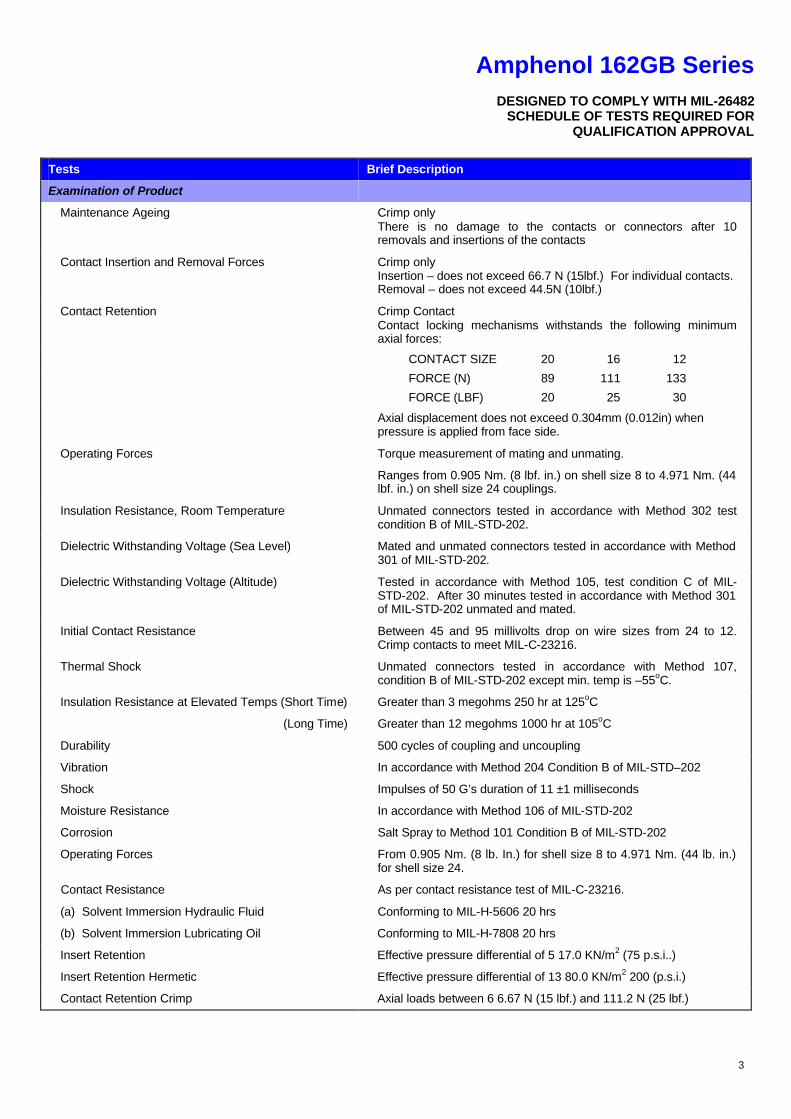
Table of Shell Styles
PLAIN SHELL
THREADED SHELL
GROMMET SEAL
STRAIN RELIEF CLAMP (For details of Right Angle Strain Relief Clamps, see Page 20)
THREADED SHELL
GROMMET SEAL
STRAIN RELIEF CLAMP (For details of Right Angle Strain Relief Clamps, see Page
BOX MOUNTING RECEPTACLES (4-hole Fixing)
Page
BOX MOUNTING RECEPTACLES(4-hole Fixing)
Page
SINGLE HOLE FIXING RECEPTACLES
Page
162GB 12E
162GB 30T
162GB 14E
162GB
162GB 10F
162GB 14F
10E
CABLE MOUNTING RECEPTACLES
Page
NON GROUNDED PLUGS Page
162GB 31T
162GB 36T
11E 162GB 16E 162GB
16F 162GB 11F 162GB
CC1304 CC1305
162GB 37T
GROUNDED PLUGS Page
162GB 36TG
6
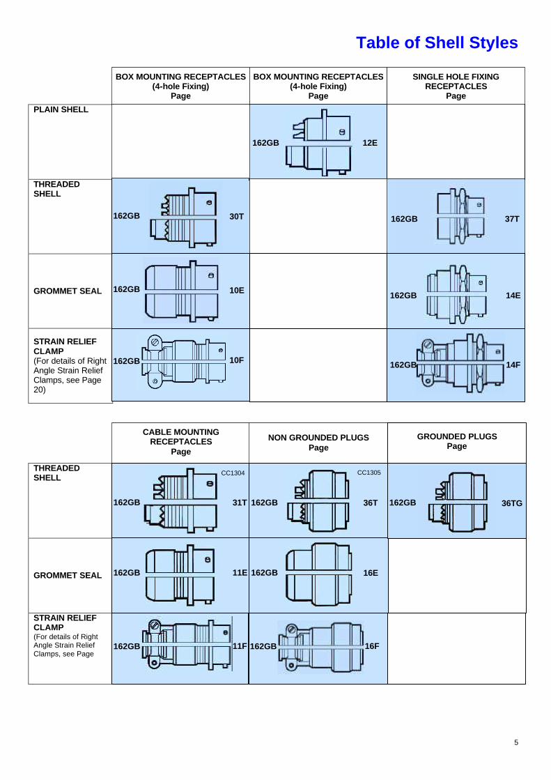
Insert Availability
8 10 12 14 16 18 20
Notes * These insert arrangements are not included in Pattern 105 but are available and listed in MIL- C-26482. † Due to the arrangement of contacts in the 14-12 insert arrangement it is classified, for current derating, in the shell size range 18-24. Lettering of inserts shown above corresponds to views of front (mating) surface of pin inserts or rear face (cable accessory end) of socket inserts. KEY ? No. 16 size contacts ? No. 20 size contacts No. 12 size contacts
8-03 10-06
10-02 12-03 14-05 16-08 18-11
14-19
14-15
14-12† 12-10 16-23*
16-26
18-32 20-41
15
10
5
0
CU
RR
EN
T –
AM
PS
PE
R C
ON
TA
CT
CU
RR
EN
T –
AM
PS
PE
R C
ON
TA
CT
0
1
2
3
4
5
SIZE 20 CONTACTS SIZE 16 CONTACTS
-55 -25 0 25 50 75 100 125
AMBIENT TEMPERATURE oC Current-temperature derating curve
8-98
8-33 10-07
20-16
16-04
12-08

7
Insert Availability
22 24
Rating 3 Sea Level 1013 mbart
8500m (27,900 ft) 320 mbar
21,340m (70,000 ft) 44 mbar
Working Voltage Working Voltages ** (nominal) d.c. or a.c. peak Voltage Proof d.c. or a.c. peak
III 1500
3000
III 800
1300
III 450
750
162GB only
Altitude
Rating 1 Sea Level 300mb at 20oC 8.500m (27,800 ft) 44 mb at 20oC 20,000 m (66,000 ft) Rating 2 Sea Level 300mb at 20oC 8.500m (27,800 ft) 44 mb at 20oC 20,000 m (66,000 ft)
dc Working Voltage
700
375
200
1250
550
300
ac Working Voltage r.m.s.
500
265
140
900
390
210
Proof Voltage
500
265
140
3250
1750
775
FLA
SH
OV
ER
VO
LTA
GE
kW
4
3
2
1
020 (6)
40 (12)
60 (18)
80 (24)
100 (30)
120 (36)
140 (42)
160 (48)
180 (54)
ALTITUDE – THOUSANDS OF FEET (METRES) Relationship between flashover voltage and altitude
for each voltage rating
(Figures in bold type are from DEF STAN 59-35 (Part 1) Sec. 3 Patt. 105)
NOTES Because safe working voltages at altitude above sea-level are dependent upon individual conditions of use, these values are not specified in DEF STAN 59-35 (Part 1) Sec. 3 Patt. 105 but approximate values are included here for the guidance of designs. VOLTAGE RATINGS Two categories of voltage rating are specified in DEF STAN 59-35 (Part 1) Sec. 3 Patt. 105. Rating 1 (700V d.c. working at sea-level) Applicable to the high contact density inserts shown in the upper section of the insert availability diagram above. Rating 2 (1250V d.c. working at sea-level) Applicable to the inserts shown in the lower section of the insert availability diagram. Rating 3 (1500V d.c. working at sea-level) (a) Maximum current per individual contact (in isolation)* at ambient temperature of 85oC Contact Size 12: 23A (b) Maximum current per contact through all contacts simultaneously at an ambient temperature of 85oC Contact Size 12: 20A Altitude Derating Information on voltage derating for operation at altitudes above se-level can be obtained from the flashover voltage altitude curves on the left.
VOLTAGE RATING 2
VOLTAGE RATING 1
Working Voltage
8
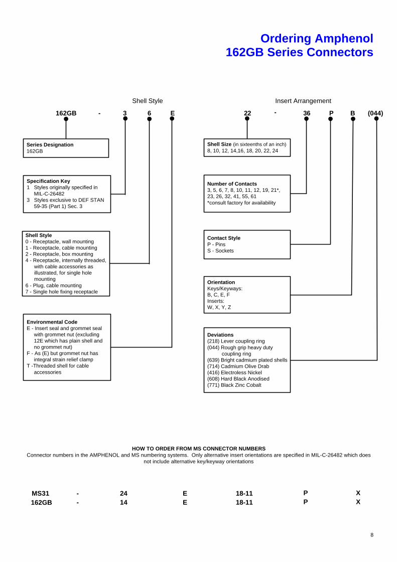
Ordering Amphenol 162GB Series Connectors
HOW TO ORDER FROM MS CONNECTOR NUMBERS Connector numbers in the AMPHENOL and MS numbering systems. Only alternative insert orientations are specified in MIL-C-26482 which does
not include alternative key/keyway orientations
MS31 - 24 E 18-11 P162GB - 14 E 18-11 P
XX
Deviations(218) Lever coupling ring(044) Rough grip heavy duty coupling ring(639) Bright cadmium plated shells(714) Cadmium Olive Drab(416) Electroless Nickel(608) Hard Black Anodised(771) Black Zinc Cobalt
OrientationKeys/Keyways:B, C, E, FInserts:W, X, Y, Z
Series Designation162GB
Specification Key1 Styles originally specified in MIL-C-264823 Styles exclusive to DEF STAN 59-35 (Part 1) Sec. 3
Shell Style0 - Receptacle, wall mounting1 - Receptacle, cable mounting2 - Receptacle, box mounting4 - Receptacle, internally threaded, with cable accessories as illustrated, for single hole mounting6 - Plug, cable mounting7 - Single hole fixing receptacle
Environmental CodeE - Insert seal and grommet seal with grommet nut (excluding 12E which has plain shell and no grommet nut)F - As (E) but grommet nut has integral strain relief clampT -Threaded shell for cable accessories
162GB - 3 6 E
Shell Style
Shell Size (in sixteenths of an inch)8, 10, 12, 14,16, 18, 20, 22, 24
Number of Contacts3, 5, 6, 7, 8, 10, 11, 12, 19, 21*,23, 26, 32, 41, 55, 61*consult factory for availability
Contact StyleP - PinsS - Sockets
22 36 P B (044)
Insert Arrangement
-
9
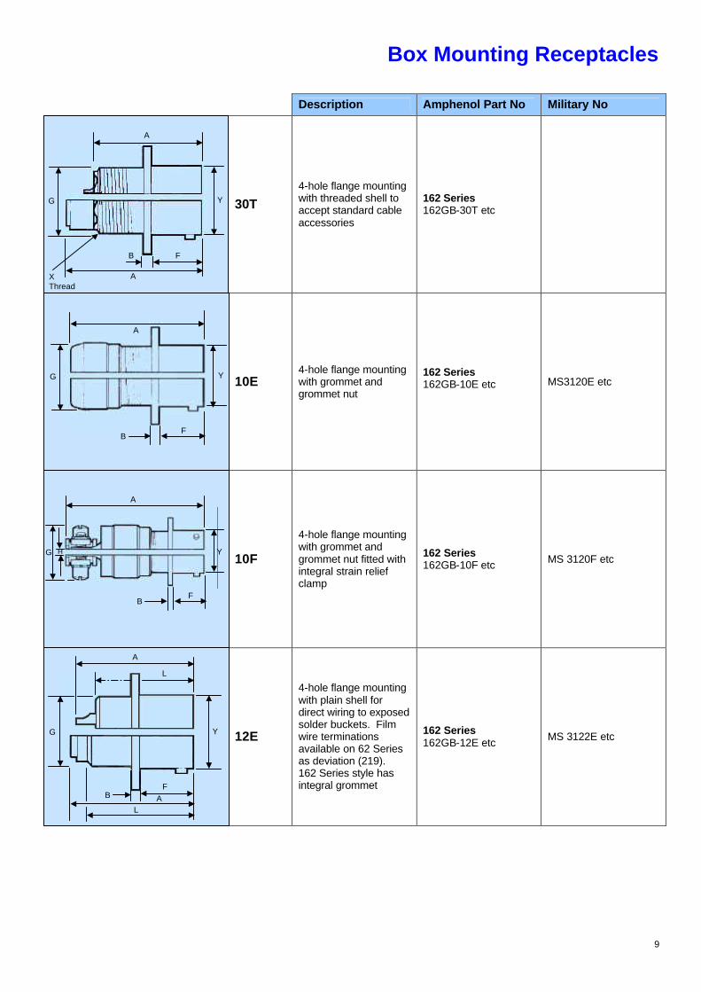
Box Mounting Receptacles
Description Amphenol Part No Military No
30T 4-hole flange mounting with threaded shell to accept standard cable accessories
162 Series 162GB-30T etc
10E 4-hole flange mounting with grommet and grommet nut
162 Series 162GB-10E etc MS3120E etc
10F
4-hole flange mounting with grommet and grommet nut fitted with integral strain relief clamp
162 Series 162GB-10F etc MS 3120F etc
12E
4-hole flange mounting with plain shell for direct wiring to exposed solder buckets. Film wire terminations available on 62 Series as deviation (219). 162 Series style has integral grommet
162 Series 162GB-12E etc MS 3122E etc
A
Y
A
F B
X Thread
G
Y
A
G
F B
H Y
A
G
F B
Y
A
L
G
L A B
F
10
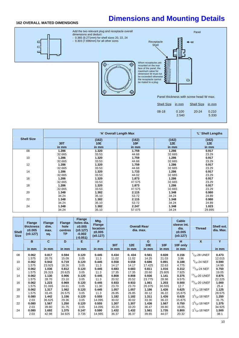
Dimensions and Mounting Details
‘A’ Overall Length Max ‘L’ Shell Lengths
Shell Size 30T
in mm
(162) 10E
in mm
(162) 10F
in mm
(162) 12E
in mm
(162) 12E
in mm 08
10
12
14
16
18
20
22
24
1.286 32.665 1.286
32.665 1.286
32.665 1.286
32.665 1.286
32.665 1.286
32.665 1.348 34.24 1.348 34.24 1.348 34.24
1.320 33.53 1.320 33.53 1.320 33.53 1.320 33.53 1.320 33.53 1.320 33.53 1.382 35.10 1.382 35.10 1.382 35.10
1.759 44.68 1.759 44.68 1.759 44.68 1.733 44.02 1.873
47.575 1.873
47.575 2.115 53.72 2.115 53.72 2.247
57.075
1.286 32.665 1.286
32.665 1.286
32.665 1.286
32.665 1.286
32.665 1.286
32.665 1.348 34.24 1.348 34.24 1.348 34.24
0.917 23.29 0.917 23.29 0.917 23.29 0.917 23.29 0.917 23.29 0.917 23.29 0.980 24.89 0.980 24.89 1.023
29.895
Flange thickness
±0.005 (±0.127)
Flange dim. max. sq.
Flange hole
centres TP
Flange holes dia.
±0.005 (±0.127) -0.002
(-0.051)
Mtg. Flange
location ±0.005
(±0.127)
Overall Rear dia. max.
Cable sleeve int.
dia. ±0.005
(±0.127)
Thread Shell ext. dia. Max.
Shell Size
B
in mm
C
in mm
D
in mm
E
in mm
F
in mm
30T
in mm
12E
in mm
G 10E
in mm
10F
in mm
H 10F only
in mm
X Y
in mm
08
10
12
14
16
18
20
22
24
0.062 1.575 0.062 1.575 0.062 1.575 0.062 1.575 0.062 1.575 0.062 1.575 0.080 2.03
0.080 2.03
0.080 2.03
0.817 20.75 0.942
23.925 1.036
26.315 1.130 28.70 1.223
31.065 1.317 33.45 1.442
36.625 1.567 39.80 1.692 42.98
0.594 15.09 0.719 18.26 0.812
20.625 0.906 23.10 0.969 24.61 1.062
26.575 1.156 29.36 1.250 31.75 1.375
34.925
0.120 3.05
0.120 3.05
0.120 3.05
0.120 3.05
0.120 3.05
0.120 3.05
0.120 3.05
0.120 3.05
0.147 3.735
0.445 11.3
0.445 11.3
0.445 11.3
0.445 11.3
0.445 11.30 0.445 11.3
0.555 14.095 0.555
14.095 0.590
14.985
0.434 11.02 0.558 14.17 0.683 17.35 0.808 20.52 0.933 23.70 1.057 26.85 1.182 30.02 1.307 33.20 1.432 36.37
0. 434 11.02 0.558 14.17 0.683 17.35 0.808 20.52 0.933 23.70 1.057 26.85 1.182 30.02 1.307 33.20 1.432 36.37
0.561 14.25 0.686
17.425 0.811 20.60 0.936
23.775 1.061
26.975 1.186 30.12 1.311 33.30 1.436 36.47 1.561 39.65
0.828 21.03 0.891 22.63 1.016
25.805 1.141 28.98 1.203
30.555 1.426 36.22 1.426 36.22 1.567 39.80 1.735 44.07
0.156 3.96 0.188 4.775 0.312 7.925 0.375 9.575 0.500 12.7 0.625
15.875 0.625
15.875 0.750 19.05 0.800 20.32
7/16-28 UNEF
9/16-24 NEF
11/16-24 NEF
13/16-20 UNEF
15/16-20 UNEF
11/16-18 NEF
13/16-18 NEF
15/16-18 NEF
17/16-18 NEF
0.473 12.015 0.590 14.99 0.750 19.05 0.875
22.225 1.000 25.4 1.125
28.575 1.250 31.75 1.375
34.925 1.500 38.1
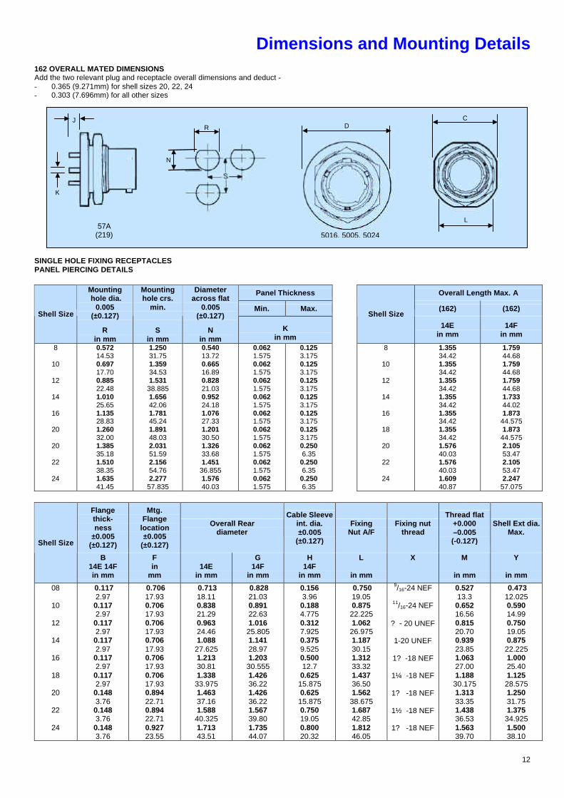
162 OVERALL MATED DIMENSIONS
Add the two relevant plug and receptacle overall dimensions and deduct: - 0.365 (9.271mm) for shell sizes 20, 22, 24 - 0.303 (7.696mm) for all other sizes
When receptacles are mounted on the rear face of the panel, the maximum value for dimension W must not be exceeded otherwise the receptacle cannot be mated to a plug
Receptacle Shell
Panel
Panel thickness with screw head W max. Shell Size in mm Shell Size in mm 08-18 0.100 20-24 0.210 2.540 5.330
W
11
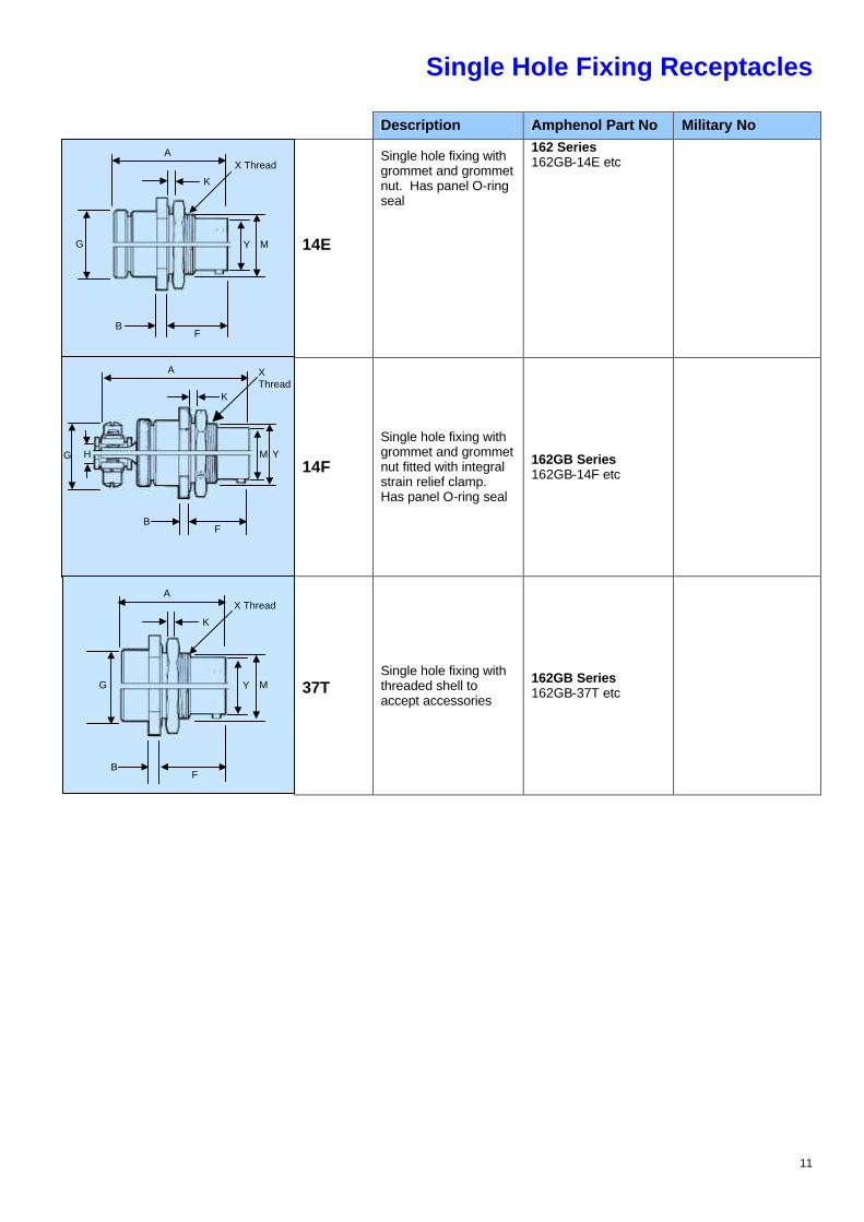
Single Hole Fixing Receptacles
Description Amphenol Part No Military No
14E
Single hole fixing with grommet and grommet nut. Has panel O-ring seal
162 Series 162GB-14E etc
14F
Single hole fixing with grommet and grommet nut fitted with integral strain relief clamp. Has panel O-ring seal
162GB Series 162GB-14F etc
37T Single hole fixing with threaded shell to accept accessories
162GB Series 162GB-37T etc
A
G
B F
Y M
K
X Thread
Y M
F B
H
A
K
G
X Thread
A
G
B F
Y M
K
X Thread
12
Dimensions and Mounting Details 162 OVERALL MATED DIMENSIONS Add the two relevant plug and receptacle overall dimensions and deduct - - 0.365 (9.271mm) for shell sizes 20, 22, 24 - 0.303 (7.696mm) for all other sizes SINGLE HOLE FIXING RECEPTACLES PANEL PIERCING DETAILS
Panel Thickness Overall Length Max. A
Min. Max.
(162) (162) Shell Size
Mounting hole dia.
0.005 (±0.127)
R in mm
Mounting hole crs.
min.
S in mm
Diameter across flat
0.005 (±0.127)
N in mm
K in mm
Shell Size
14E in mm
14F in mm
8
10
12
14
16
20
20
22
24
0.572 14.53 0.697 17.70 0.885 22.48 1.010 25.65 1.135 28.83 1.260 32.00 1.385 35.18 1.510 38.35 1.635 41.45
1.250 31.75 1.359 34.53 1.531
38.885 1.656 42.06 1.781 45.24 1.891 48.03 2.031 51.59 2.156 54.76 2.277
57.835
0.540 13.72 0.665 16.89 0.828 21.03 0.952 24.18 1.076 27.33 1.201 30.50 1.326 33.68 1.451
36.855 1.576 40.03
0.062 1.575 0.062 1.575 0.062 1.575 0.062 1.575 0.062 1.575 0.062 1.575 0.062 1.575 0.062 1.575 0.062 1.575
0.125 3.175 0.125 3.175 0.125 3.175 0.125 3.175 0.125 3.175 0.125 3.175 0.250 6.35
0.250 6.35
0.250 6.35
8
10
12
14
16
18
20
22
24
1.355 34.42 1.355 34.42 1.355 34.42 1.355 34.42 1.355 34.42 1.355 34.42 1.576 40.03 1.576 40.03 1.609 40.87
1.759 44.68 1.759 44.68 1.759 44.68 1.733 44.02 1.873
44.575 1.873
44.575 2.105 53.47 2.105 53.47 2.247
57.075
Flange thick- ness
±0.005 (±0.127)
Mtg. Flange
location ±0.005
(±0.127)
Overall Rear diameter
Cable Sleeve int. dia. ±0.005
(±0.127)
Fixing Nut A/F
Fixing nut thread
Thread flat +0.000 –0.005 (-0.127)
Shell Ext dia. Max.
Shell Size
B 14E 14F in mm
F in
mm
14E
in mm
G 14F
in mm
H 14F
in mm
L
in mm
X M
in mm
Y
in mm
08
10
12
14
16
18
20
22
24
0.117 2.97 0.117 2.97 0.117 2.97 0.117 2.97 0.117 2.97 0.117 2.97 0.148 3.76 0.148 3.76 0.148 3.76
0.706 17.93 0.706 17.93 0.706 17.93 0.706 17.93 0.706 17.93 0.706 17.93 0.894 22.71 0.894 22.71 0.927 23.55
0.713 18.11 0.838 21.29 0.963 24.46 1.088 27.625 1.213 30.81 1.338 33.975 1.463 37.16 1.588 40.325 1.713 43.51
0.828 21.03 0.891 22.63 1.016 25.805 1.141 28.97 1.203 30.555 1.426 36.22 1.426 36.22 1.567 39.80 1.735 44.07
0.156 3.96 0.188 4.775 0.312 7.925 0.375 9.525 0.500 12.7 0.625 15.875 0.625 15.875 0.750 19.05 0.800 20.32
0.750 19.05 0.875 22.225 1.062 26.975 1.187 30.15 1.312 33.32 1.437 36.50 1.562 38.675 1.687 42.85 1.812 46.05
9/16-24 NEF
11/16-24 NEF
? - 20 UNEF
1-20 UNEF
1? -18 NEF
1¼ -18 NEF
1? -18 NEF
1½ -18 NEF
1? -18 NEF
0.527 13.3 0.652 16.56 0.815 20.70 0.939 23.85 1.063 27.00 1.188 30.175 1.313 33.35 1.438 36.53 1.563 39.70
0.473 12.025 0.590 14.99 0.750 19.05 0.875 22.225 1.000 25.40 1.125 28.575 1.250 31.75 1.375 34.925 1.500 38.10
J
K
57A (219) 5016, 5005, 5024
D R
N
C
L
13
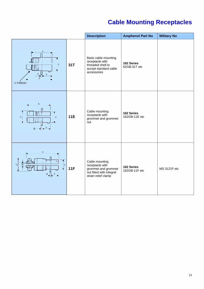
Cable Mounting Receptacles
Description Amphenol Part No Military No
31T
Basic cable mounting receptacle with threaded shell to accept standard cable accessories
162 Series 62GB-31T etc
11E Cable mounting receptacle with grommet and grommet nut
162 Series 162GB-11E etc
11F
Cable mounting receptacle with grommet and grommet nut fitted with integral strain relief clamp
162 Series 162GB-11F etc MS 3121F etc
X THREAD
14
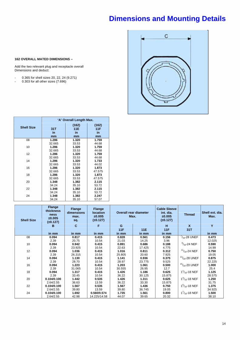
Dimensions and Mounting Details
162 OVERALL MATED DIMENSIONS – Add the two relevant plug and receptacle overall Dimensions and deduct: - 0.365 for shell sizes 20, 22, 24 (9.271) - 0.303 for all other sizes (7.696)
‘A’ Overall Length Max.
Shell Size
31T in
mm
(162) 11E in
mm
(162) 11F in
mm 08
10
12
14
16
18
20
22
24
1.286 32.665 1.286
32.665 1.286
32.665 1.286
32.665 1.286
32.665 1.286
32.665 1.348 34.24 1.348 34.24 1.348 34.24
1.320 33.53 1.320 33.53 1.320 33.53 1.320 33.53 1.320 33.53 1.320 33.53 1.382 35.10 1.382 35.10 1.382 35.10
1.759 44.68 1.759 44.68 1.759 44.68 1.733 44.02 1.873
47.575 1.873
47.575 2.115 53.72 2.115 53.72 2.247 57.07
Flange
thickness ness
±0.005 (±0.127)
Flange dimensions
max. sq.
Flange location ±0.005
(±0.127)
Overall rear diameter Max.
Cable Sleeve int. dia. ±0.005
(±0.127)
Thread Shell ext. dia.
Max.
B C F G H X Y
Shell Size
in mm
in mm
in mm
11F in mm
11E in mm
11F in mm
31T in mm
08
10
12
14
16
18
20
22
24
0.094 2.39
0.094 2.39
0.094 2.39
0.094 2.39
0.094 2.39
0.094 2.39
0.104/0.100 2.64/2.55
0.104/0.100 2.64/2.55
0.104/0.100 2.64/2.55
0.817 20.75 0.942
23.925 1.036
26.315 1.130 28.70 1.223
31.065 1.317 33.45 1.442 36.63 1.567 39.80 1.692 42.98
0.415 10.54 0.415 10.54 0.415 10.54 0.415 10.54 0.415 10.54 0.415 10.54 0.535 13.59 0.535 13.59
0.560/0.574 14.225/14.58
0.828 21.03 0.891 22.63 1.016
25.805 1.141 28.97 1.203
30.555 1.426 36.22 1.426 36.22 1.567 39.80 1.735 44.07
0.561 14.25 0.686
17.425 0.811 20.60 0.936
23.775 1.061 26.95 1.186
30.125 1.311 33.30 1.436
36.745 1.561 39.65
0.156 3.96
0.188 4.775 0.312 7.925 0.375 9.525 0.500 12.7
0.625 15.875 0.625
15.875 0.750 19.05 0.800 20.32
7/16-28 UNEF
9/16-24 NEF
11/16-24 NEF
13/16-28 UNEF
15/16-20 UNEF
11/16-18 NEF
13/16-18 NEF
15/16-18 NEF
17/16-18 NEF
0.473 12.025 0.590 14.99 0.750 19.05 0.875
22.225 1.000 25.4
1.125 28.575 1.250 31.75 1.375
34.925 1.500 38.10
15
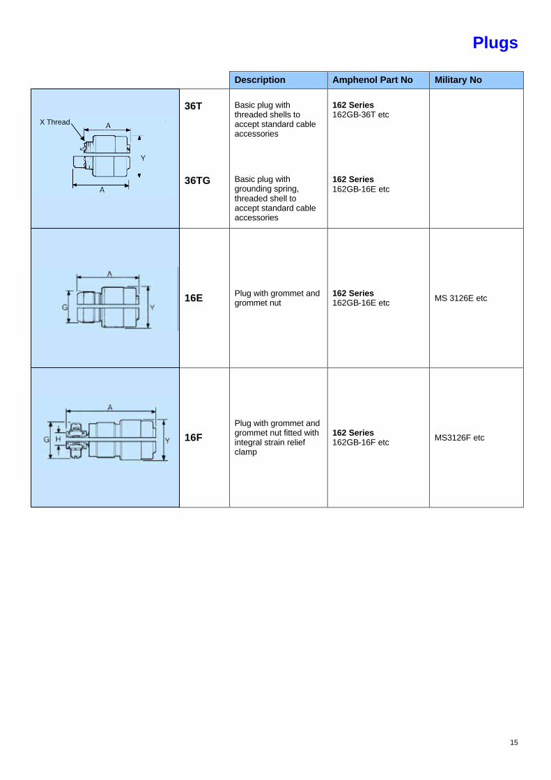
Plugs
Description Amphenol Part No Military No
36T
36TG
Basic plug with threaded shells to accept standard cable accessories
Basic plug with grounding spring, threaded shell to accept standard cable accessories
162 Series 162GB-36T etc
162 Series 162GB-16E etc
16E Plug with grommet and grommet nut
162 Series 162GB-16E etc MS 3126E etc
16F Plug with grommet and grommet nut fitted with integral strain relief clamp
162 Series 162GB-16F etc MS3126F etc
X Thread
16
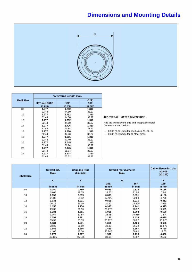
Dimensions and Mounting Details
‘A’ Overall Length max.
Shell Size 36T and 36TG
in mm
16F
in mm
(162) 16E
in mm 08
10
12
14
16
18
20
22
24
1.277 32.44 1.277 32.44 1.277 32.44 1.277 32.44 1.277 32.44 1.277 32.44 1.277 32.44 1.277 32.44 1.277 32.44
1.752 44.50 1.752 44.50 1.752 44.50 1.726 43.84 1.866 47.40 1.866 47.40 2.045 51.94 2.045 51.94 2.178 55.32
1.310 33.27 1.310 33.27 1.310 33.27 1.310 33.27 1.310 33.27 1.310 33.27 1.310 33.27 1.310 33.27 1.310 33.27
162 OVERALL MATED DIMENSIONS – Add the two relevant plug and receptacle overall Dimensions and deduct: - 0.365 (9.271mm) for shell sizes 20, 22, 24 - 0.303 (7.696mm) for all other sizes
Overall dia. Max.
Coupling Ring dia. max.
Overall rear diameter Max.
Cable Sleeve int. dia. ±0.005
(±0.127)
C Y G H
Shell Size
in mm
in mm
16E in mm
16F in mm
16F in mm
08
10
12
14
16
18
20
22
24
0.750 19.05 0.859 21.82 1.031 26.19 1.156 29.36 1.281 32.54 1.391 35.33 1.531 38.89 1.656 42.06 1.777
45.135
0.750 19.05 0.859 21.82 1.031 26.19 1.156 29.36 1.281 32.54 1.391 35.33 1.531 38.89 1.656 42.06 1.777
45.135
0.561 14.25 0.686
17.425 0.811 20.60 0.936
23.775 1.061 26.95 1.186
30.125 1.311 33.30 1.436
36.745 1.561 39.65
0.828 21.03 0.891 22.63 1.016
25.805 1.141 28.97 1.203
30.555 1.426 36.22 1.426 36.22 1.567 39.80 1.735 44.07
0.156 3.96
0.188 4.775 0.312 7.925 0.375 9.525 0.500 12.7
0.625 15.875 0.625
15.875 0.750 19.05 0.800 20.32
17
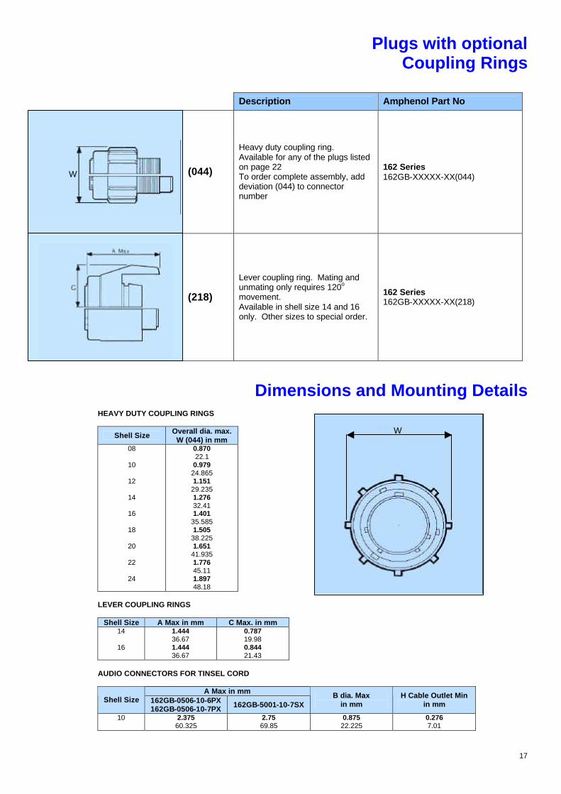
Plugs with optional Coupling Rings
Description Amphenol Part No
(044)
Heavy duty coupling ring. Available for any of the plugs listed on page 22 To order complete assembly, add deviation (044) to connector number
162 Series 162GB-XXXXX-XX(044)
(218)
Lever coupling ring. Mating and unmating only requires 120o movement. Available in shell size 14 and 16 only. Other sizes to special order.
162 Series 162GB-XXXXX-XX(218)
Dimensions and Mounting Details
HEAVY DUTY COUPLING RINGS
Shell Size Overall dia. max. W (044) in mm
08
10
12
14
16
18
20
22
24
0.870 22.1
0.979 24.865 1.151
29.235 1.276 32.41 1.401
35.585 1.505
38.225 1.651
41.935 1.776 45.11 1.897 48.18
LEVER COUPLING RINGS
Shell Size A Max in mm C Max. in mm
14
16
1.444 36.67 1.444 36.67
0.787 19.98 0.844 21.43
AUDIO CONNECTORS FOR TINSEL CORD
A Max in mm Shell Size 162GB-0506-10-6PX
162GB-0506-10-7PX 162GB-5001-10-7SX B dia. Max
in mm H Cable Outlet Min
in mm
10 2.375 60.325
2.75 69.85
0.875 22.225
0.276 7.01
W
W
18
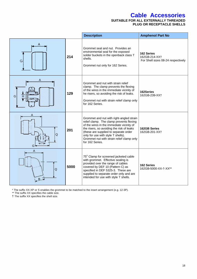
Cable Accessories SUITABLE FOR ALL EXTERNALLY THREADED
PLUG OR RECEPTACLE SHELLS
Description Amphenol Part No
214
Grommet seal and nut. Provides an environmental seal for the exposed solder buckets in the openback class T shells. Grommet nut only for 162 Series.
162 Series 162GB-214-XX† For Shell sizes 08-24 respectively
129
Grommet and nut with strain relief clamp. The clamp prevents the flexing of the wires in the immediate vicinity of he risers, so avoiding the risk of leaks. Grommet nut with strain relief clamp only for 162 Series.
162Series 162GB-239-XX†
201
Grommet and nut with right-angled strain relief clamp. The clamp prevents flexing of the wires in the immediate vicinity of the risers, so avoiding the risk of leaks (these are supplied to separate order only for use with style T shells). Grommet nut with strain relief clamp only for 162 Series.
162GB Series 162GB-201-XX†
5000
75o Clamp for screened jacketed cable with grommet. Effective sealing is provided over the range of cables covered by DEF 10 (Pattern C) as specified in DEF 5325-3. These are supplied to separate order only and are intended for use with style T shells.
162 Series 162GB-5000-XX-†-XX**
* The suffix XX-XP or S enables the grommet to be matched to the insert arrangement (e.g. 12-3P). ** The suffix XX specifies the cable size. † The suffix XX specifies the shell size.
A
G H
A
Q
G
Q
A
B

19
Dimensions and Mounting Details
CABLES TO DEF STAN 10 and DEF STAN 61-12 part 5 e.g. def 10-3A or DEF STAN 16-2-3A
PLANFORM CABLE
DEF 10-etc DEF STAN 16-2 etc
PLANFORM
CABLE DEF 10 etc DEF STAN
16-2 etc
PLANFORM
CABLE DEF 10-etc
DEF STAN 16-2 etc
8-3 3A,3B,3C,2B 14-12 C 12A,12B,12C 20-16 - 8-3 3 C 3A,3B,3C,2B 14-15 - 20-41 C 36C
10-2 2A,2B,2C,2Q• 16-8 - 22-55 - 10-6 C 6A,6B,6C,4C 16-23 C - 24-61 C 60C 12-3 C 3A,3B,3C,2Q• 16-26 25A,25B,25C 12-10 10C 18-11 - - -
• Applicable to DEF10 only
Part Number Examples:
162GB-151-14-12 (no grommet supplied)
Type A Cables: Type B Cables: Type C Cables: Type Q Cables:
PVC outer sheath, no overall screen, L.T. (14/.0076) unscreened cores (equivalent DEF STAN 16-2 wire size) Outer screen, inner PVC sheath, L.T. (14.0076) unscreened cores (equivalent DEF STAN 16-2 wire size) Outer PVC sheath, inner screen, L.T. (14.0076) unscreened cores (equivalent DEF STAN 16-2 wire size) Outer screen, inner PVC sheath, L.T. (36/.012) unscreened cores (DEF 10 only)
Overall Length (max.) Straight SJ Clamps 162GB-151-XX max
75o SJ Clamps 162GB-5000-XX max
Shell Size 162GB-201-XX 162GB-129-XX
in mm 162GB-160-168
in mm Length including
plug in mm
Length including receptacle
in mm
Length including plug
in mm
Length including receptacle in mm
08
10
12
14
16
18
20
22
24
15/32
13/16
17/32
11/4
15/16
13/8
13/8
129/64
115/32
0.991 25.17 0.991 25.17 0.991 25.17 0.965 24.51 1.105
28.065 1.105
28.065 1.285 32.64 1.285 32.64 1.373
34.875
0.545 13.84 0.545 13.84 0.545 13.84 0.545 13.84 0.545 13.84 0.545 13.84 0.545 13.84 0.545 13.84 0.501
12.725
2.732 69.39 2.742 69.64 3.152 80.06 3.152 80.06 3.272 83.10
- -
3.272 83.10
- -
3.696 93.87
2.742 69.64 2.752 69.90 3.162 80.31 3.162 80.31 3.282 83.36
- -
3.345 84.96
- -
3.768 95.70
2.375 60.235 2.532 64.39 2.625
66.675 2.719
69.035 2.750 69.80
- -
3.250 82.55
- -
3.375 85.725
2.416 61.365 2.573 65.35 2.666
67.715 2.760
70.095 2.790 70.87
- -
3.312 84.125
- -
3.500 88.90
B dia. max G J K L
Shell Size 162GB-151-XX 162GB-5000-XX
in mm
162GB-129-XX in mm
162GB-214 P or S in mm
All SJ Clamps in mm
Cable Sleeve Int. dia. ±0.005
±0.127
162GB-201-XX in mm
36T 162GB-5000-XX
in mm 08
10
12
14
16
18
20
22
24
0.676 17.17 0.676 17.17 0.812 20.62 0.926 23.52 1.051
26.695 - -
1.280 32.51
- -
1.620 41.15
0.828 21.03 0.891 22.63 1.016
25.805 1.141 28.98 1.203
30.555 1.426 36.22 1.426 36.22 1.567 39.80 1.735 44.07
0.561 14.25 0.686
17.425 0.811 20.60 0.936
23.775 1.061 26.95 1.186
30.125 1.311 33.30 1.436
36.745 1.561 39.65
0.775 19.68 0.902 22.91 1.030 26.16 1.157
29.385 1.284 32.61
- -
1.539 39.09
- -
1.783 45.29
0.161 4.09 0.193 4.90 0.317 8.05 0.380 9.65 0.505 12.83 0.630 16.00 0.630 16.00 0.755
19.175 0.805 20.45
0.733 18.62 0.795 20.19 0.858 21.79 0.915 23.24 1.010 25.65 1.070 27.18 1.140
28.955 1.170 29.72 1.260 32.00
1.750 44.45 1.875
47.625 2.125
53.975 2.125
53.975 2.062
52.375 - -
2.062 52.375
- -
2.187 55.55
SJ CLAMPS The 162 series clamps are identical to the 62 series clamps except that the grommet is omitted. It is however, still necessary to quote the full planform because the piece parts vary to suit the appropriate cable. SJ clamps are available in 62 series only where there is an appropriate cable to DEF 10 or DEF STAN 61-12 part 5 available for the planform. 162 series availability is similar according to the planforms tooled. These are marked C on the table.

20
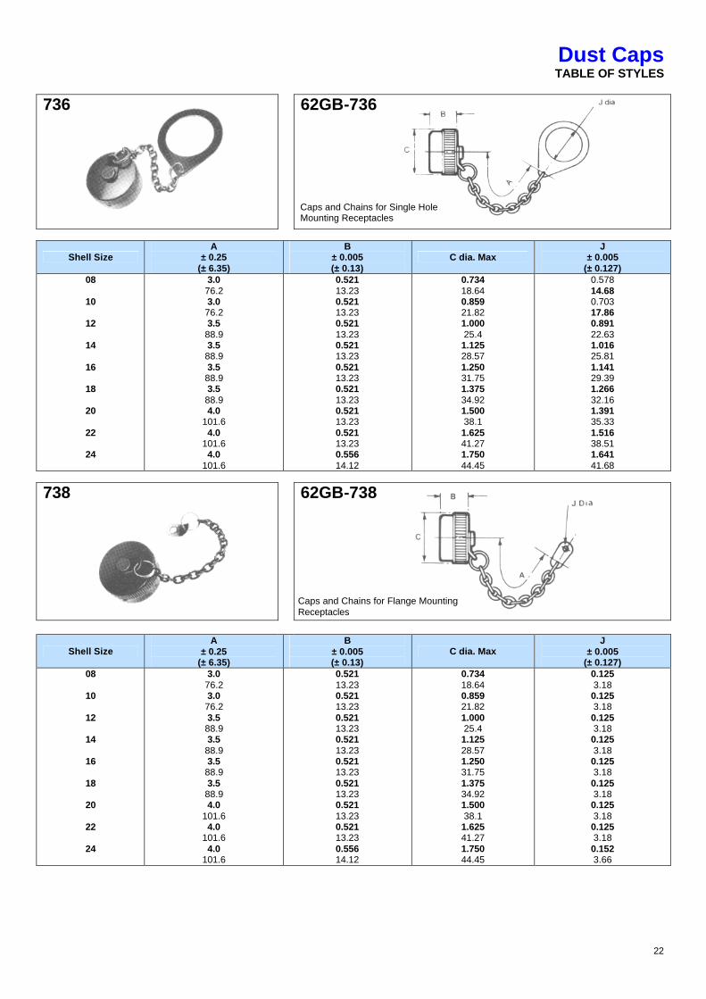
Dust Caps TABLE OF STYLES
62GB-736
62GB-738
62GB-742
62GB-810
62GB-812
62GB-813
21
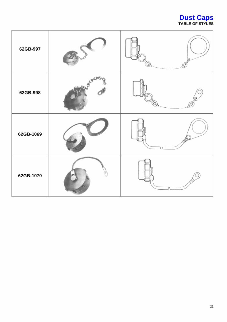
Dust Caps TABLE OF STYLES
62GB-997
62GB-998
62GB-1069
62GB-1070
22
Dust Caps TABLE OF STYLES
736
62GB-736
Shell Size A
± 0.25 (± 6.35)
B ± 0.005 (± 0.13)
C dia. Max J
± 0.005 (± 0.127)
08
10
12
14
16
18
20
22
24
3.0 76.2 3.0 76.2 3.5 88.9 3.5 88.9 3.5 88.9 3.5 88.9 4.0
101.6 4.0
101.6 4.0
101.6
0.521 13.23 0.521 13.23 0.521 13.23 0.521 13.23 0.521 13.23 0.521 13.23 0.521 13.23 0.521 13.23 0.556 14.12
0.734 18.64 0.859 21.82 1.000 25.4 1.125 28.57 1.250 31.75 1.375 34.92 1.500 38.1 1.625 41.27 1.750 44.45
0.578 14.68 0.703 17.86 0.891 22.63 1.016 25.81 1.141 29.39 1.266 32.16 1.391 35.33 1.516 38.51 1.641 41.68
738
62GB-738
Shell Size A
± 0.25 (± 6.35)
B ± 0.005 (± 0.13)
C dia. Max J
± 0.005 (± 0.127)
08
10
12
14
16
18
20
22
24
3.0 76.2 3.0 76.2 3.5 88.9 3.5 88.9 3.5 88.9 3.5 88.9 4.0
101.6 4.0
101.6 4.0
101.6
0.521 13.23 0.521 13.23 0.521 13.23 0.521 13.23 0.521 13.23 0.521 13.23 0.521 13.23 0.521 13.23 0.556 14.12
0.734 18.64 0.859 21.82 1.000 25.4 1.125 28.57 1.250 31.75 1.375 34.92 1.500 38.1 1.625 41.27 1.750 44.45
0.125 3.18 0.125 3.18 0.125 3.18 0.125 3.18 0.125 3.18 0.125 3.18 0.125 3.18 0.125 3.18 0.152 3.66
Caps and Chains for Single Hole Mounting Receptacles
Caps and Chains for Flange Mounting Receptacles
23
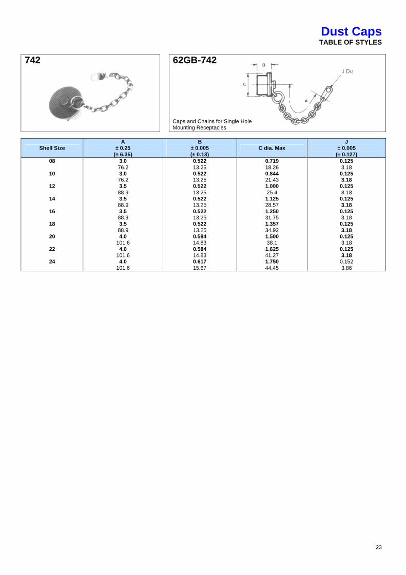
Dust Caps TABLE OF STYLES
742
62GB-742
Shell Size A
± 0.25 (± 6.35)
B ± 0.005 (± 0.13)
C dia. Max J
± 0.005 (± 0.127)
08
10
12
14
16
18
20
22
24
3.0 76.2 3.0 76.2 3.5 88.9 3.5 88.9 3.5 88.9 3.5 88.9 4.0
101.6 4.0
101.6 4.0
101.6
0.522 13.25 0.522 13.25 0.522 13.25 0.522 13.25 0.522 13.25 0.522 13.25 0.584 14.83 0.584 14.83 0.617 15.67
0.719 18.26 0.844 21.43 1.000 25.4 1.125 28.57 1.250 31.75 1.357 34.92 1.500 38.1 1.625 41.27 1.750 44.45
0.125 3.18 0.125 3.18 0.125 3.18 0.125 3.18 0.125 3.18 0.125 3.18 0.125 3.18 0.125 3.18 0.152 3.86
Caps and Chains for Single Hole Mounting Receptacles
24
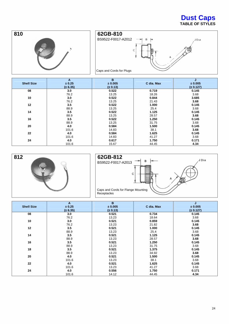
Dust Caps TABLE OF STYLES
810
62GB-810
Shell Size A
± 0.25 (± 6.35)
B ± 0.005 (± 0.13)
C dia. Max J
± 0.005 (± 0.127)
08
10
12
14
16
20
22
24
3.0 76.2 3.0 76.2 3.5 88.9 3.5 88.9 3.5 88.9 4.0
101.6 4.0
101.6 4.0
101.6
0.522 13.25 0.522 13.25 0.522 13.25 0.522 13.25 0.522 13.25 0.584 14.83 0.584 14.83 0.617 15.67
0.719 18.26 0.844 21.43 1.000 25.4 1.125 28.57 1.250 31.75 1.500 38.1 1.625 41.27 1.750 44.45
0.145 3.68 3.685 3.68 0.145 3.68 0.145 3.68 0.145 3.68 0.145 3.68 0.145 3.68 0.171 4.34
812
62GB-812
Shell Size A
± 0.25 (± 6.35)
B ± 0.005 (± 0.13)
C dia. Max J
± 0.005 (± 0.127)
08
10
12
14
16
18
20
22
24
3.0 76.2 3.0 76.2 3.5 88.9 3.5 88.9 3.5 88.9 3.5 88.9 4.0
101.6 4.0
101.6 4.0
101.6
0.521 13.23 0.521 13.23 0.521 13.23 0.521 13.23 0.521 13.23 0.521 13.23 0.521 13.23 0.521 13.23 0.556 14.12
0.734 18.64 0.859 21.82 1.000 25.4 1.125 28.57 1.250 31.75 1.375 34.92 1.500 38.1 1.625 41.27 1.750 44.45
0.145 3.68 0.145 3.68 0.145 3.68 0.145 3.68 0.145 3.68 0.145 3.68 0.145 3.68 0.145 3.68 0.171 4.34
Caps and Cords for Plugs
BS9522-F0017-A2013
Caps and Cords for Flange Mounting Receptacles
BS9522-F0017-A2012

25
Dust Caps TABLE OF STYLES
813
62GB-813
Shell Size A
± 0.25 (± 6.35)
B ± 0.005 (± 0.13)
C dia. Max J
± 0.005 (± 0.127)
08
10
12
14
16
18
20
22
24
3.0 76.2 3.0 76.2 3.5 88.9 3.5 88.9 3.5 88.9 3.5 88.9 4.0
101.6 4.0
101.6 4.0
101.6
0.521 13.23 0.521 13.23 0.521 13.23 0.521 13.23 0.521 13.23 0.521 13.23 0.521 13.23 0.521 13.23 0.556 14.12
0.734 18.64 0.859 21.82 1.000 25.4 1.125 28.57 1.250 31.75 1.375 34.92 1.500 38.1 1.625 41.27 1.750 44.45
0.578 14.68 0.703 17.86 0.891 22.63 1.016 25.81 1.141 29.39 1.266 32.16 1.391 35.33 1.516 38.56 1.641 41.68
BS9522-F0017-A2014
Caps and Cords for Single Hole Mounting Receptacles
26
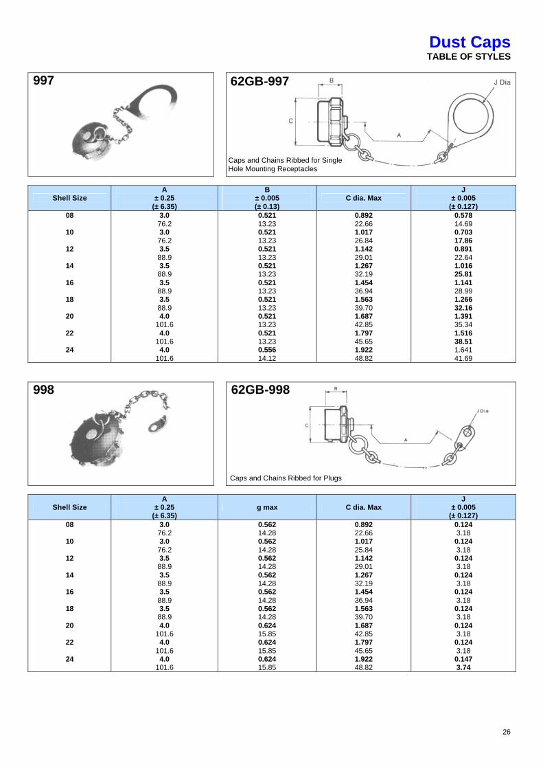
Dust Caps TABLE OF STYLES
997
Shell Size A
± 0.25 (± 6.35)
B ± 0.005 (± 0.13)
C dia. Max J
± 0.005 (± 0.127)
08
10
12
14
16
18
20
22
24
3.0 76.2 3.0 76.2 3.5 88.9 3.5 88.9 3.5 88.9 3.5 88.9 4.0
101.6 4.0
101.6 4.0
101.6
0.521 13.23 0.521 13.23 0.521 13.23 0.521 13.23 0.521 13.23 0.521 13.23 0.521 13.23 0.521 13.23 0.556 14.12
0.892 22.66 1.017 26.84 1.142 29.01 1.267 32.19 1.454 36.94 1.563 39.70 1.687 42.85 1.797 45.65 1.922 48.82
0.578 14.69 0.703 17.86 0.891 22.64 1.016 25.81 1.141 28.99 1.266 32.16 1.391 35.34 1.516 38.51 1.641 41.69
998
62GB-998
Shell Size A
± 0.25 (± 6.35)
g max C dia. Max J
± 0.005 (± 0.127)
08
10
12
14
16
18
20
22
24
3.0 76.2 3.0 76.2 3.5 88.9 3.5 88.9 3.5 88.9 3.5 88.9 4.0
101.6 4.0
101.6 4.0
101.6
0.562 14.28 0.562 14.28 0.562 14.28 0.562 14.28 0.562 14.28 0.562 14.28 0.624 15.85 0.624 15.85 0.624 15.85
0.892 22.66 1.017 25.84 1.142 29.01 1.267 32.19 1.454 36.94 1.563 39.70 1.687 42.85 1.797 45.65 1.922 48.82
0.124 3.18 0.124 3.18 0.124 3.18 0.124 3.18 0.124 3.18 0.124 3.18 0.124 3.18 0.124 3.18 0.147 3.74
Caps and Chains Ribbed for Single Hole Mounting Receptacles
62GB-997
Caps and Chains Ribbed for Plugs
27
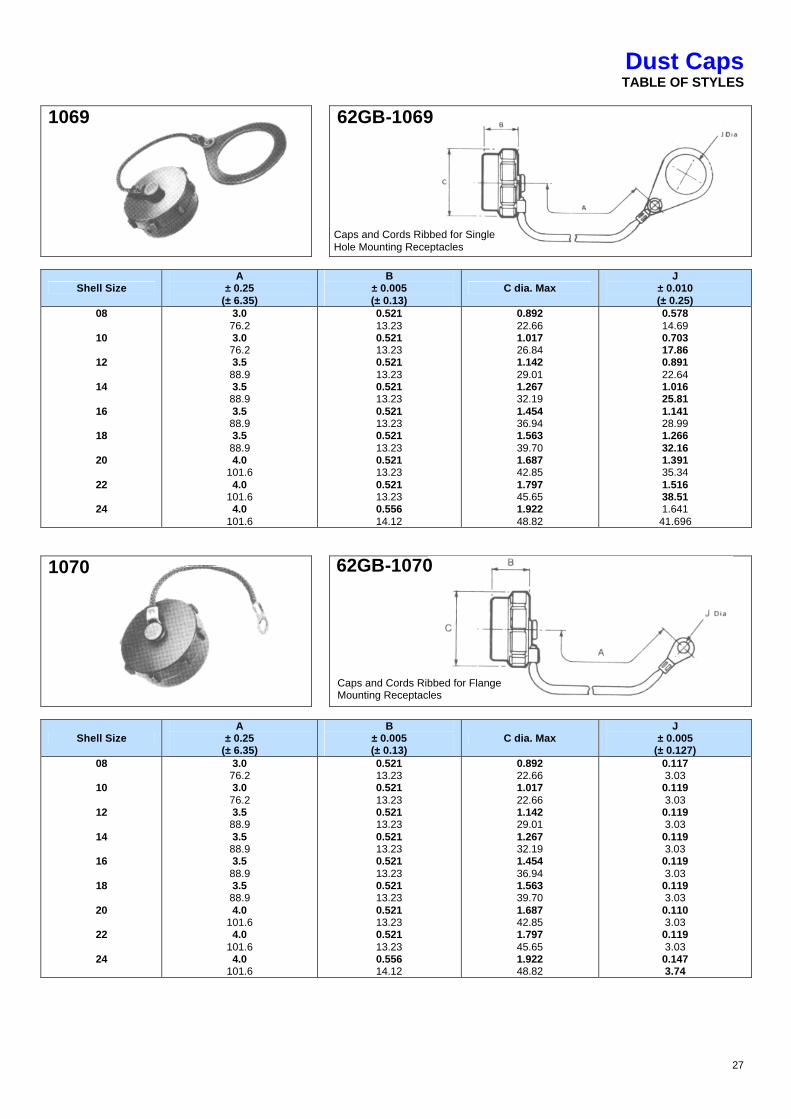
Dust Caps TABLE OF STYLES
1069
Shell Size A
± 0.25 (± 6.35)
B ± 0.005 (± 0.13)
C dia. Max J
± 0.010 (± 0.25)
08
10
12
14
16
18
20
22
24
3.0 76.2 3.0 76.2 3.5 88.9 3.5 88.9 3.5 88.9 3.5 88.9 4.0
101.6 4.0
101.6 4.0
101.6
0.521 13.23 0.521 13.23 0.521 13.23 0.521 13.23 0.521 13.23 0.521 13.23 0.521 13.23 0.521 13.23 0.556 14.12
0.892 22.66 1.017 26.84 1.142 29.01 1.267 32.19 1.454 36.94 1.563 39.70 1.687 42.85 1.797 45.65 1.922 48.82
0.578 14.69 0.703 17.86 0.891 22.64 1.016 25.81 1.141 28.99 1.266 32.16 1.391 35.34 1.516 38.51 1.641 41.696
1070
Shell Size A
± 0.25 (± 6.35)
B ± 0.005 (± 0.13)
C dia. Max J
± 0.005 (± 0.127)
08
10
12
14
16
18
20
22
24
3.0 76.2 3.0 76.2 3.5 88.9 3.5 88.9 3.5 88.9 3.5 88.9 4.0
101.6 4.0
101.6 4.0
101.6
0.521 13.23 0.521 13.23 0.521 13.23 0.521 13.23 0.521 13.23 0.521 13.23 0.521 13.23 0.521 13.23 0.556 14.12
0.892 22.66 1.017 22.66 1.142 29.01 1.267 32.19 1.454 36.94 1.563 39.70 1.687 42.85 1.797 45.65 1.922 48.82
0.117 3.03 0.119 3.03 0.119 3.03 0.119 3.03 0.119 3.03 0.119 3.03 0.110 3.03 0.119 3.03 0.147 3.74
62GB-1069
Caps and Cords Ribbed for Single Hole Mounting Receptacles
62GB-1070
Caps and Cords Ribbed for Flange Mounting Receptacles
28
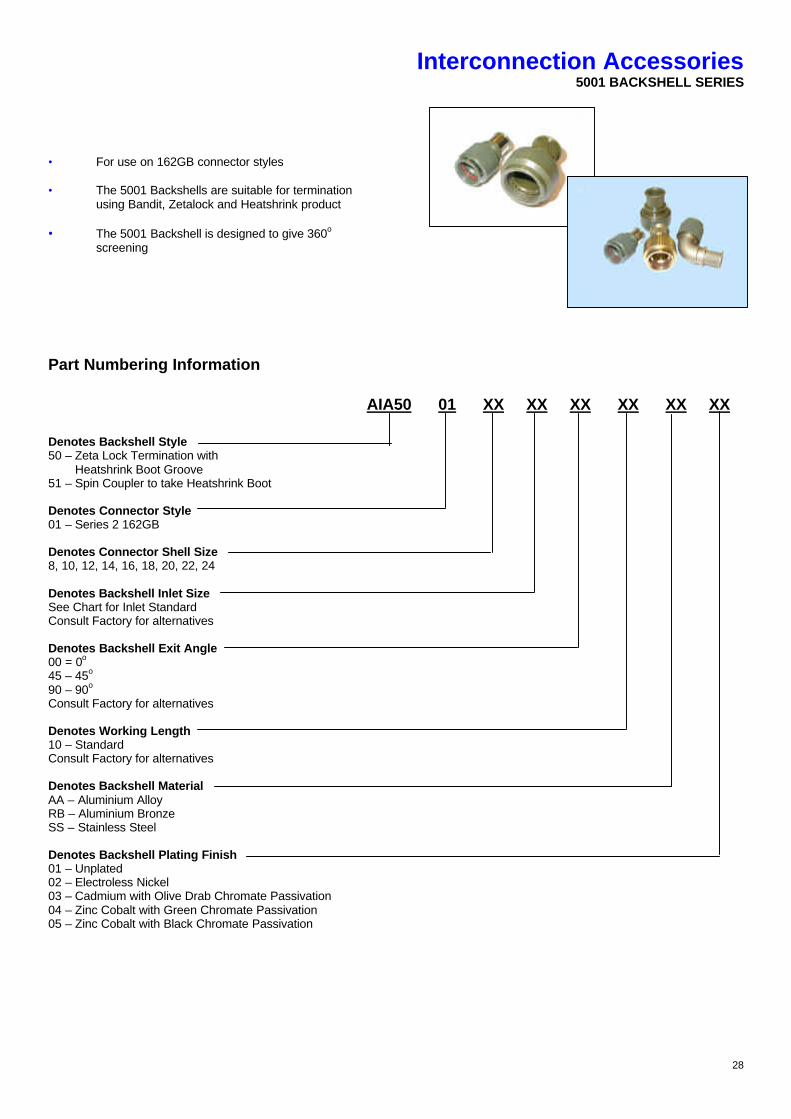
Interconnection Accessories 5001 BACKSHELL SERIES
• For use on 162GB connector styles
• The 5001 Backshells are suitable for termination
using Bandit, Zetalock and Heatshrink product
• The 5001 Backshell is designed to give 360o screening
Part Numbering Information AIA50 01 XX XX XX XX XX XX Denotes Backshell Style 50 – Zeta Lock Termination with Heatshrink Boot Groove 51 – Spin Coupler to take Heatshrink Boot Denotes Connector Style 01 – Series 2 162GB Denotes Connector Shell Size 8, 10, 12, 14, 16, 18, 20, 22, 24 Denotes Backshell Inlet Size See Chart for Inlet Standard Consult Factory for alternatives Denotes Backshell Exit Angle 00 = 0o 45 – 45o 90 – 90o Consult Factory for alternatives Denotes Working Length 10 – Standard Consult Factory for alternatives Denotes Backshell Material AA – Aluminium Alloy RB – Aluminium Bronze SS – Stainless Steel Denotes Backshell Plating Finish 01 – Unplated 02 – Electroless Nickel 03 – Cadmium with Olive Drab Chromate Passivation 04 – Zinc Cobalt with Green Chromate Passivation 05 – Zinc Cobalt with Black Chromate Passivation

29
Interconnection Accessories 5001 BACKSHELL SERIES - STRAIGHT
Part Number A-Thread ØB MAX ØG MAX ØH MAX Rec Hellerman Boot 90o
Rec Hellerman Boot Straight Spring Ref
5001-08-00-00-10-AA-XX
5001-10-00-00-10-AA-XX
5001-12-00-00-10-AA-XX
5001-14-00-00-10-AA-XX
5001-16-00-00-10-AA-XX
5001-18-00-00-10-AA-XX
5001-20-00-00-10-AA-XX
5001-22-00-00-10-AA-XX
5001-24-00-00-10-AA-XX
5001-08-06-00-10-AA-XX
5001-10-08-00-10-AA-XX
5001-12-10-00-10-AA-XX
5001-14-12-00-10-AA-XX
5001-16-14-00-10-AA-XX
5001-18-16-00-10-AA-XX
5001-20-18-00-10-AA-XX
5001-22-20-00-10-AA-XX
5001-24-22-00-10-AA-XX
7/16-28 UNEF
9/16-24 UNEF
11/16-24 UNEF
13/16-20 UNEF
15/16-20 UNEF
1 1/16-18 UNEF
1 3/16-18 UNEF
1 5/16-18 UNEF
1 7/16-18 UNEF
7/16-28 UNEF
9/16-24 UNEF
11/16-24 UNEF
13/16-20 UNEF
15/16-20 UNEF
1 1/16-18 UNEF
1 3/16-18 UNEF
1 5/16-18 UNEF
1 7/16-18 UNEF
18.14
20.45
24.64
29.13
32.13
32.64
39.78
43.28
44.25
18.14
20.45
24.64
29.13
32.13
32.64
39.78
43.28
44.25
6.48
8.05
11.25
12.83
16.00
19.18
22.38
25.55
25.55
4.83
6.48
8.05
11.25
12.83
16.00
19.18
22.38
25.55
14.04
15.61
18.81
20.39
23.57
26.74
29.92
33.09
33.09
14.04
14.04
15.61
18.81
20.39
23.57
26.74
29.92
33.09
1152-4-GW24
1154-4-GW24
1155-4-GW24
1155-4-GW24
1156-4-GW24
1156-4-GW24
1157-4-GW24
1157-4-GW24
1157-4-GW24
1152-4-GW24
1154-4-GW24
1155-4-GW24
1155-4-GW24
1156-4-GW24
1156-4-GW24
1157-4-GW24
1157-4-GW24
1157-4-GW24
152-42-GW24
154-42-GW24
155-42-GW24
155-42-GW24
155-42-GW24
156-42-GW24
157-43-GW24
157-43-GW24
157-43-GW24
152-42-GW24
154-42-GW24
155-42-GW24
155-42-GW24
156-42-GW24
156-42-GW24
157-43-GW24
157-43-GW24
157-43-GW24
HE 050
HE 100
HE 100
HE 200
HE 200
HE 300
HE 300
HE 300
HE 300
HE 050
HE 050
HE 100
HE 100
HE 200
HE 200
HE 300
HE 300
HE 300
All dimensions in mm
36.35 MAX
29.95 MAX
ØB
MA
X
A T
HR
EA
D
ØG
MA
X
ØH
MA
X
30
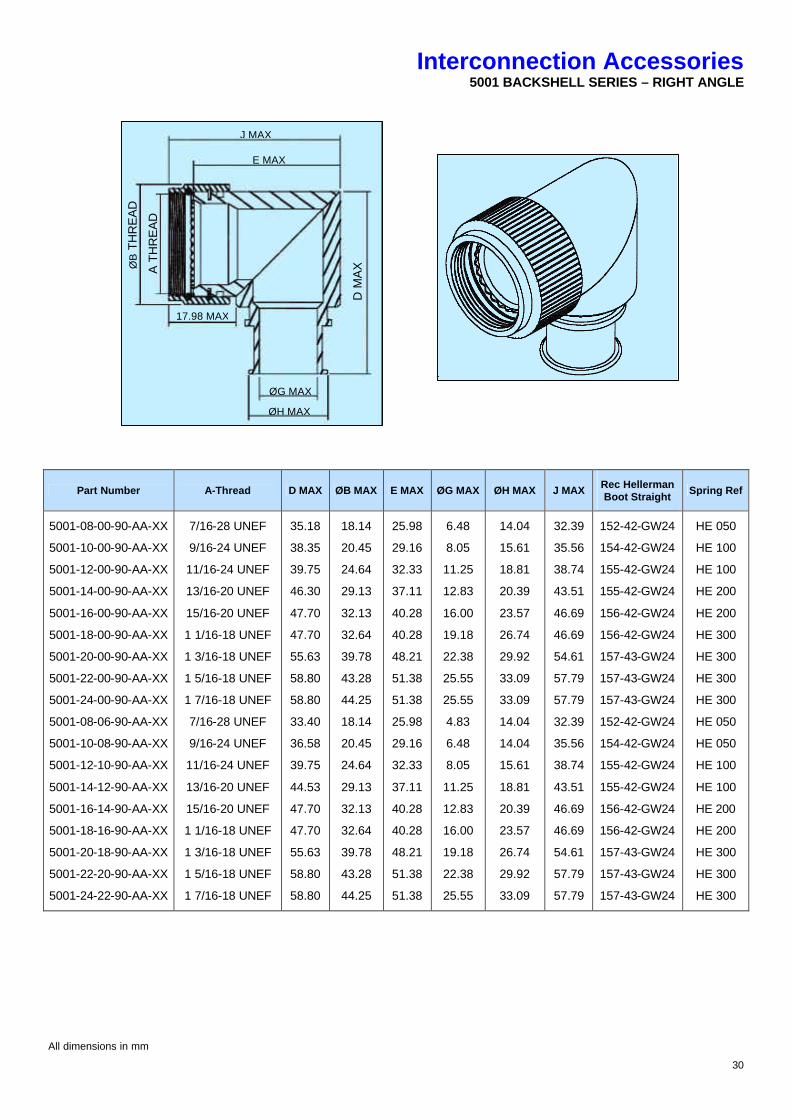
Interconnection Accessories 5001 BACKSHELL SERIES – RIGHT ANGLE
Part Number A-Thread D MAX ØB MAX E MAX ØG MAX ØH MAX J MAX Rec Hellerman Boot Straight
Spring Ref
5001-08-00-90-AA-XX
5001-10-00-90-AA-XX
5001-12-00-90-AA-XX
5001-14-00-90-AA-XX
5001-16-00-90-AA-XX
5001-18-00-90-AA-XX
5001-20-00-90-AA-XX
5001-22-00-90-AA-XX
5001-24-00-90-AA-XX
5001-08-06-90-AA-XX
5001-10-08-90-AA-XX
5001-12-10-90-AA-XX
5001-14-12-90-AA-XX
5001-16-14-90-AA-XX
5001-18-16-90-AA-XX
5001-20-18-90-AA-XX
5001-22-20-90-AA-XX
5001-24-22-90-AA-XX
7/16-28 UNEF
9/16-24 UNEF
11/16-24 UNEF
13/16-20 UNEF
15/16-20 UNEF
1 1/16-18 UNEF
1 3/16-18 UNEF
1 5/16-18 UNEF
1 7/16-18 UNEF
7/16-28 UNEF
9/16-24 UNEF
11/16-24 UNEF
13/16-20 UNEF
15/16-20 UNEF
1 1/16-18 UNEF
1 3/16-18 UNEF
1 5/16-18 UNEF
1 7/16-18 UNEF
35.18
38.35
39.75
46.30
47.70
47.70
55.63
58.80
58.80
33.40
36.58
39.75
44.53
47.70
47.70
55.63
58.80
58.80
18.14
20.45
24.64
29.13
32.13
32.64
39.78
43.28
44.25
18.14
20.45
24.64
29.13
32.13
32.64
39.78
43.28
44.25
25.98
29.16
32.33
37.11
40.28
40.28
48.21
51.38
51.38
25.98
29.16
32.33
37.11
40.28
40.28
48.21
51.38
51.38
6.48
8.05
11.25
12.83
16.00
19.18
22.38
25.55
25.55
4.83
6.48
8.05
11.25
12.83
16.00
19.18
22.38
25.55
14.04
15.61
18.81
20.39
23.57
26.74
29.92
33.09
33.09
14.04
14.04
15.61
18.81
20.39
23.57
26.74
29.92
33.09
32.39
35.56
38.74
43.51
46.69
46.69
54.61
57.79
57.79
32.39
35.56
38.74
43.51
46.69
46.69
54.61
57.79
57.79
152-42-GW24
154-42-GW24
155-42-GW24
155-42-GW24
156-42-GW24
156-42-GW24
157-43-GW24
157-43-GW24
157-43-GW24
152-42-GW24
154-42-GW24
155-42-GW24
155-42-GW24
156-42-GW24
156-42-GW24
157-43-GW24
157-43-GW24
157-43-GW24
HE 050
HE 100
HE 100
HE 200
HE 200
HE 300
HE 300
HE 300
HE 300
HE 050
HE 050
HE 100
HE 100
HE 200
HE 200
HE 300
HE 300
HE 300
All dimensions in mm
J MAX
E MAX
ØG MAX
ØH MAX
A T
HR
EA
D
ØB
TH
RE
AD
17.98 MAX
D M
AX
31
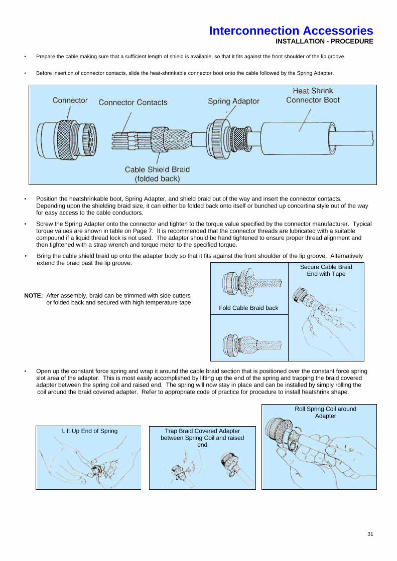
Interconnection Accessories INSTALLATION - PROCEDURE
• Prepare the cable making sure that a sufficient length of shield is available, so that it fits against the front shoulder of the lip groove.
• Before insertion of connector contacts, slide the heat-shrinkable connector boot onto the cable followed by the Spring Adapter.
• Position the heatshrinkable boot, Spring Adapter, and shield braid out of the way and insert the connector contacts.
Depending upon the shielding braid size, it can either be folded back onto itself or bunched up concertina style out of the way for easy access to the cable conductors.
• Screw the Spring Adapter onto the connector and tighten to the torque value specified by the connector manufacturer. Typical torque values are shown in table on Page 7. It is recommended that the connector threads are lubricated with a suitable compound if a liquid thread lock is not used. The adapter should be hand tightened to ensure proper thread alignment and then tightened with a strap wrench and torque meter to the specified torque.
• Bring the cable shield braid up onto the adapter body so that it fits against the front shoulder of the lip groove. Alternatively extend the braid past the lip groove.
NOTE: After assembly, braid can be trimmed with side cutters or folded back and secured with high temperature tape • Open up the constant force spring and wrap it around the cable braid section that is positioned over the constant force spring
slot area of the adapter. This is most easily accomplished by lifting up the end of the spring and trapping the braid covered adapter between the spring coil and raised end. The spring will now stay in place and can be installed by simply rolling the
coil around the braid covered adapter. Refer to appropriate code of practice for procedure to install heatshrink shape.
Lift Up End of Spring Trap Braid Covered Adapter between Spring Coil and raised
end
Roll Spring Coil around Adapter
Secure Cable Braid End with Tape
Fold Cable Braid back

32
Interconnection Accessories INSTALLATION - PROCEDURE
Re-Entry Procedure • Reheat the heatshrink shape, remove to expose the ZetalokTM? spring and braid.
• Once spring is exposed, lift up the edge of the ZetalokTM spring and push it around the circumference of the assembly to form a coil which can then be rolled around the assembly to remove the spring.
• Lift the cable screen braid off the backshell and push it back out of the way.
• Unscrew the backshell and push it back out to facilitate repairs at the connector or exposed connector area.
• Follow the practice detailed in these instructions to re-install the ZetalokTM spring backshell
Note: The ZetalokTM? spring can be installed and removed an infinite number of times if not bent or distorted in any way during the
removal process.
33
Interconnection Accessories SHIELD TERMINATION ASSEMBLY PROCESS
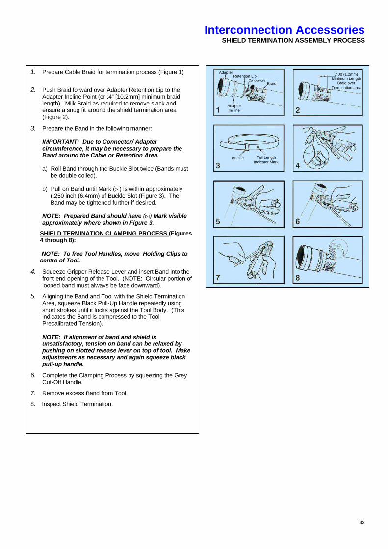
1. Prepare Cable Braid for termination process (Figure 1)
2. Push Braid forward over Adapter Retention Lip to the Adapter Incline Point (or .4” [10.2mm] minimum braid length). Milk Braid as required to remove slack and ensure a snug fit around the shield termination area (Figure 2).
3. Prepare the Band in the following manner: IMPORTANT: Due to Connector/ Adapter circumference, it may be necessary to prepare the Band around the Cable or Retention Area. a) Roll Band through the Buckle Slot twice (Bands must be double-coiled). b) Pull on Band until Mark (ûæ) is within approximately (.250 inch (6.4mm) of Buckle Slot (Figure 3). The Band may be tightened further if desired. NOTE: Prepared Band should have (ûæ) Mark visible approximately where shown in Figure 3.
SHIELD TERMINATION CLAMPING PROCESS (Figures 4 through 8): NOTE: To free Tool Handles, move Holding Clips to centre of Tool.
4. Squeeze Gripper Release Lever and insert Band into the front end opening of the Tool. (NOTE: Circular portion of looped band must always be face downward).
5. Aligning the Band and Tool with the Shield Termination Area, squeeze Black Pull-Up Handle repeatedly using short strokes until it locks against the Tool Body. (This indicates the Band is compressed to the Tool Precalibrated Tension). NOTE: If alignment of band and shield is unsatisfactory, tension on band can be relaxed by pushing on slotted release lever on top of tool. Make adjustments as necessary and again squeeze black pull-up handle.
6. Complete the Clamping Process by squeezing the Grey Cut-Off Handle.
7. Remove excess Band from Tool.
8. Inspect Shield Termination.
Adapter Retention Lip
Conductors Braid
Adapter Incline
Buckle Tail Length Indicator Mark
.400 (1.2mm) Minimum Length
Braid over Termination area
34
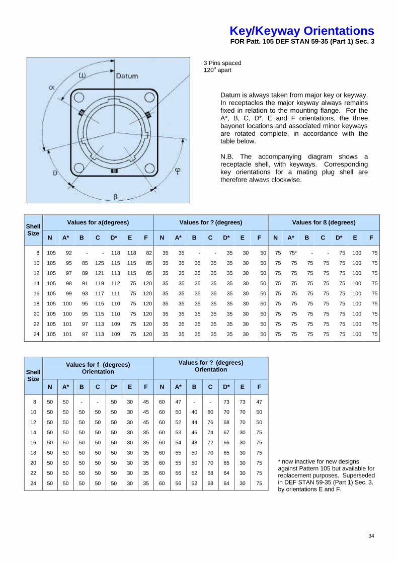
Key/Keyway Orientations FOR Patt. 105 DEF STAN 59-35 (Part 1) Sec. 3
Values for a(degrees) Values for ? (degrees) Values for ß (degrees) Shell Size
N A* B C D* E F N A* B C D* E F N A* B C D* E F
8
10
12
14
16
18
20
22
24
105
105
105
105
105
105
105
105
105
92
95
97
98
99
100
100
101
101
-
85
89
91
93
95
95
97
97
-
125
121
119
117
115
115
113
113
118
115
113
112
111
110
110
109
109
118
115
115
75
75
75
75
75
75
82
85
85
120
120
120
120
120
120
35
35
35
35
35
35
35
35
35
35
35
35
35
35
35
35
35
35
-
35
35
35
35
35
35
35
35
-
35
35
35
35
35
35
35
35
35
35
35
35
35
35
35
35
35
30
30
30
30
30
30
30
30
30
50
50
50
50
50
50
50
50
50
75
75
75
75
75
75
75
75
75
75*
75
75
75
75
75
75
75
75
-
75
75
75
75
75
75
75
75
-
75
75
75
75
75
75
75
75
75
75
75
75
75
75
75
75
75
100
100
100
100
100
100
100
100
100
75
75
75
75
75
75
75
75
75
Values for f (degrees) Orientation
Values for ? (degrees) Orientation Shell
Size N A* B C D* E F N A* B C D* E F
8
10
12
14
16
18
20
22
24
50
50
50
50
50
50
50
50
50
50
50
50
50
50
50
50
50
50
-
50
50
50
50
50
50
50
50
-
50
50
50
50
50
50
50
50
50
50
50
50
50
50
50
50
50
30
30
30
30
30
30
30
30
30
45
45
45
35
35
35
35
35
35
60
60
60
60
60
60
60
60
60
47
50
52
53
54
55
55
56
56
-
40
44
46
48
50
50
52
52
-
80
76
74
72
70
70
68
68
73
70
68
67
66
65
65
64
64
73
70
70
30
30
30
30
30
30
47
50
50
75
75
75
75
75
75
Datum is always taken from major key or keyway. In receptacles the major keyway always remains fixed in relation to the mounting flange. For the A*, B, C, D*, E and F orientations, the three bayonet locations and associated minor keyways are rotated complete, in accordance with the table below. N.B. The accompanying diagram shows a receptacle shell, with keyways. Corresponding key orientations for a mating plug shell are therefore always clockwise.
3 Pins spaced 120o apart
* now inactive for new designs against Pattern 105 but available for replacement purposes. Superseded in DEF STAN 59-35 (Part 1) Sec. 3. by orientations E and F.
35
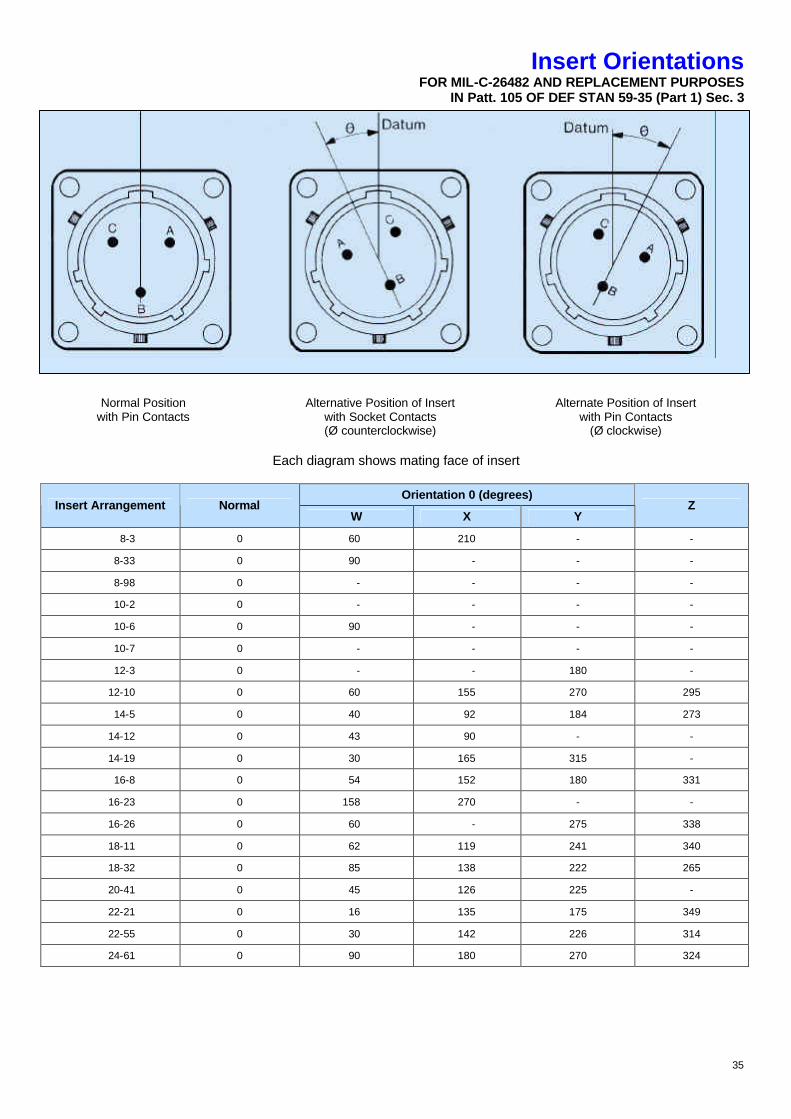
Insert Orientations FOR MIL-C-26482 AND REPLACEMENT PURPOSES
IN Patt. 105 OF DEF STAN 59-35 (Part 1) Sec. 3
Normal Position with Pin Contacts
Alternative Position of Insert with Socket Contacts (Ø counterclockwise)
Alternate Position of Insert with Pin Contacts
(Ø clockwise)
Each diagram shows mating face of insert Orientation 0 (degrees)
Insert Arrangement Normal W X Y
Z
8-3 0 60 210 - -
8-33 0 90 - - -
8-98 0 - - - -
10-2 0 - - - -
10-6 0 90 - - -
10-7 0 - - - -
12-3 0 - - 180 -
12-10 0 60 155 270 295
14-5 0 40 92 184 273
14-12 0 43 90 - -
14-19 0 30 165 315 -
16-8 0 54 152 180 331
16-23 0 158 270 - -
16-26 0 60 - 275 338
18-11 0 62 119 241 340
18-32 0 85 138 222 265
20-41 0 45 126 225 -
22-21 0 16 135 175 349
22-55 0 30 142 226 314
24-61 0 90 180 270 324
36
Assembly Instructions FOR AMPHENOL STRAIGHT S.J. CLAMPS TO
DEF STAN 59-35 (Part 1) Sec. 3 FOR INTERNALLY AND EXTERNALLY SCREENED AND UNSCREENED CABLES
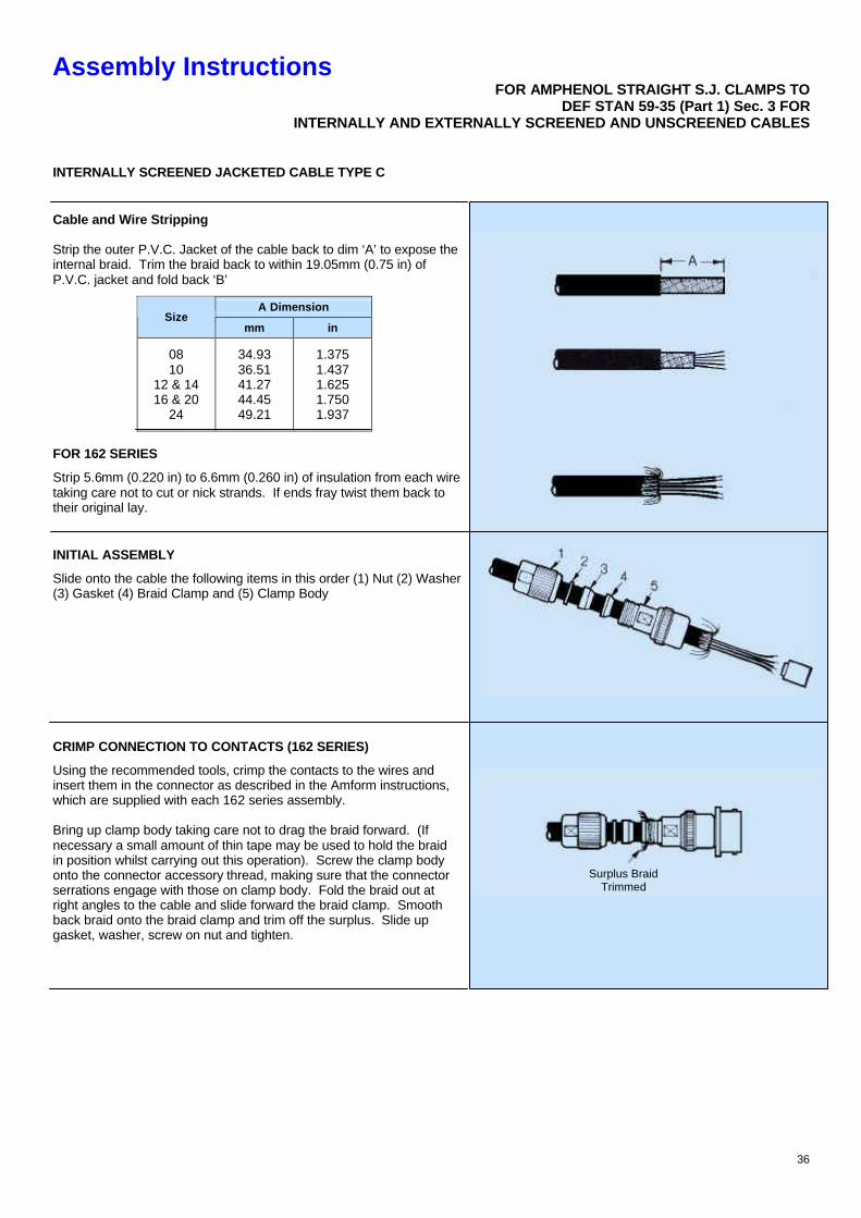
INTERNALLY SCREENED JACKETED CABLE TYPE C
Cable and Wire Stripping Strip the outer P.V.C. Jacket of the cable back to dim ‘A’ to expose the internal braid. Trim the braid back to within 19.05mm (0.75 in) of P.V.C. jacket and fold back ‘B’
A Dimension Size
mm in
08 10
12 & 14 16 & 20
24
34.93 36.51 41.27 44.45 49.21
1.375 1.437 1.625 1.750 1.937
FOR 162 SERIES
Strip 5.6mm (0.220 in) to 6.6mm (0.260 in) of insulation from each wire taking care not to cut or nick strands. If ends fray twist them back to their original lay.
INITIAL ASSEMBLY
Slide onto the cable the following items in this order (1) Nut (2) Washer (3) Gasket (4) Braid Clamp and (5) Clamp Body
CRIMP CONNECTION TO CONTACTS (162 SERIES)
Using the recommended tools, crimp the contacts to the wires and insert them in the connector as described in the Amform instructions, which are supplied with each 162 series assembly. Bring up clamp body taking care not to drag the braid forward. (If necessary a small amount of thin tape may be used to hold the braid in position whilst carrying out this operation). Screw the clamp body onto the connector accessory thread, making sure that the connector serrations engage with those on clamp body. Fold the braid out at right angles to the cable and slide forward the braid clamp. Smooth back braid onto the braid clamp and trim off the surplus. Slide up gasket, washer, screw on nut and tighten.
Surplus Braid Trimmed
37
Assembly InstructionsFOR AMPHENOL STRAIGHT S.J. CLAMPS TO
DEF STAN 59-35 (Part 1) Sec. 3 FORINTERNALLY AND EXTERNALLY SCREENED AND UNSCREENED CABLES
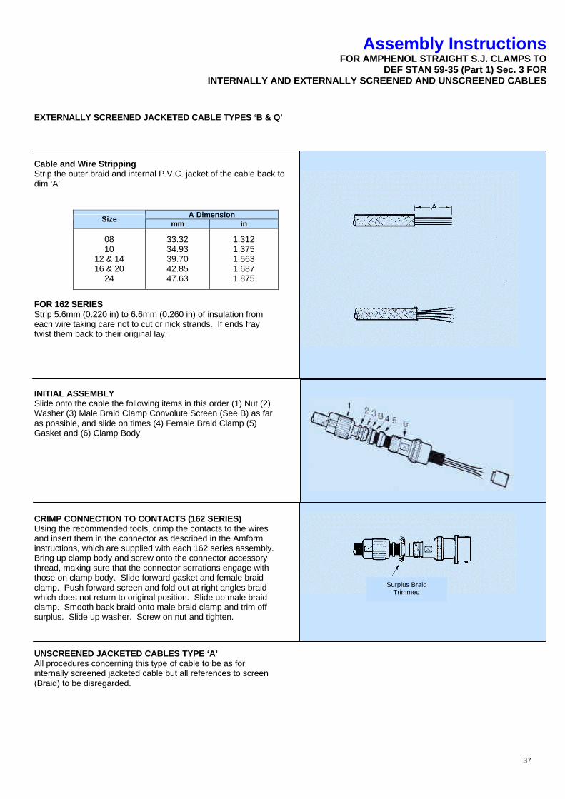
EXTERNALLY SCREENED JACKETED CABLE TYPES ‘B & Q’
Cable and Wire Stripping Strip the outer braid and internal P.V.C. jacket of the cable back to dim ‘A’
A Dimension Size mm in
08 10
12 & 14 16 & 20
24
33.32 34.93 39.70 42.85 47.63
1.312 1.375 1.563 1.687 1.875
FOR 162 SERIES Strip 5.6mm (0.220 in) to 6.6mm (0.260 in) of insulation from each wire taking care not to cut or nick strands. If ends fray twist them back to their original lay.
INITIAL ASSEMBLY Slide onto the cable the following items in this order (1) Nut (2) Washer (3) Male Braid Clamp Convolute Screen (See B) as far as possible, and slide on times (4) Female Braid Clamp (5) Gasket and (6) Clamp Body
CRIMP CONNECTION TO CONTACTS (162 SERIES) Using the recommended tools, crimp the contacts to the wires and insert them in the connector as described in the Amform instructions, which are supplied with each 162 series assembly. Bring up clamp body and screw onto the connector accessory thread, making sure that the connector serrations engage with those on clamp body. Slide forward gasket and female braid clamp. Push forward screen and fold out at right angles braid which does not return to original position. Slide up male braid clamp. Smooth back braid onto male braid clamp and trim off surplus. Slide up washer. Screw on nut and tighten.
UNSCREENED JACKETED CABLES TYPE ‘A’ All procedures concerning this type of cable to be as for internally screened jacketed cable but all references to screen (Braid) to be disregarded.
Surplus Braid Trimmed
38
Assembly Instructions FOR AMPHENOL ANGLED S.J. CLAMPS TO
DEF STAN 59-35 (Part 1) Sec. 3 FOR INTERNALLY AND EXTERNALLY SCREENED AND UNSCREENED CABLES
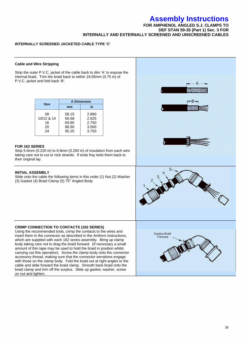
INTERNALLY SCREENED JACKETED CABLE TYPE ‘C’
Cable and Wire Stripping Strip the outer P.V.C. jacket of the cable back to dim ‘A’ to expose the internal braid. Trim the braid back to within 19.05mm (0.75 in) of P.V.C. jacket and fold back ‘B’.
A Dimension Size
mm in
08 10/12 & 14
16 20 24
58.15 66.68 69.85 88.90 95.25
2.890 2.625 2.750 3.500 3.750
FOR 162 SERIES Strip 5.6mm (0.220 in) to 6.6mm (0.260 in) of insulation from each wire taking care not to cut or nick strands. If ends fray twist them back to their original lay.
INITIAL ASSEMBLY Slide onto the cable the following items in this order (1) Nut (2) Washer (3) Gasket (4) Braid Clamp (5) 75o Angled Body
CRIMP CONNECTION TO CONTACTS (162 SERIES) Using the recommended tools, crimp the contacts to the wires and insert them in the connector as described in the Amform instructions, which are supplied with each 162 series assembly. Bring up clamp body taking care not to drag the braid forward. (If necessary a small amount of thin tape may be used to hold the braid in position whilst carrying out this operation). Screw the clamp body onto the connector accessory thread, making sure that the connector serrations engage with those on the clamp body. Fold the braid out at right angles to the cable and slide forward the braid clamp. Smooth back braid onto the braid clamp and trim off the surplus. Slide up gasket, washer, screw on nut and tighten.
Surplus Braid Trimmed
39
Assembly InstructionsFOFOR AMPHENOL ANGLED S.J. CLAMPS TO
DEF STAN 59-35 (Part 1) Sec. 3 FORINTERNALLY AND EXTERNALLY SCREENED AND UNSCREENED CABLES
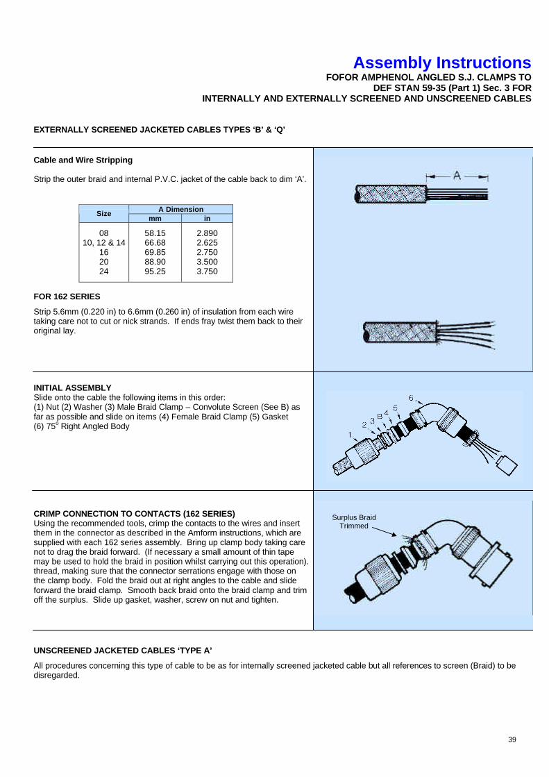
EXTERNALLY SCREENED JACKETED CABLES TYPES ‘B’ & ‘Q’
Cable and Wire Stripping Strip the outer braid and internal P.V.C. jacket of the cable back to dim ‘A’.
A Dimension Size mm in
08 10, 12 & 14
16 20 24
58.15 66.68 69.85 88.90 95.25
2.890 2.625 2.750 3.500 3.750
FOR 162 SERIES
Strip 5.6mm (0.220 in) to 6.6mm (0.260 in) of insulation from each wire taking care not to cut or nick strands. If ends fray twist them back to their original lay.
INITIAL ASSEMBLY Slide onto the cable the following items in this order: (1) Nut (2) Washer (3) Male Braid Clamp – Convolute Screen (See B) as far as possible and slide on items (4) Female Braid Clamp (5) Gasket (6) 75o Right Angled Body
CRIMP CONNECTION TO CONTACTS (162 SERIES) Using the recommended tools, crimp the contacts to the wires and insert them in the connector as described in the Amform instructions, which are supplied with each 162 series assembly. Bring up clamp body taking care not to drag the braid forward. (If necessary a small amount of thin tape may be used to hold the braid in position whilst carrying out this operation). Screw the clamp body onto the connector accessory thread, making sure that the connector serrations engage with those on the clamp body. Fold the braid out at right angles to the cable and slide forward the braid clamp. Smooth back braid onto the braid clamp and trim off the surplus. Slide up gasket, washer, screw on nut and tighten.
UNSCREENED JACKETED CABLES ‘TYPE A’
All procedures concerning this type of cable to be as for internally screened jacketed cable but all references to screen (Braid) to be disregarded.
Surplus Braid Trimmed
40
162GB Assembly Instructions
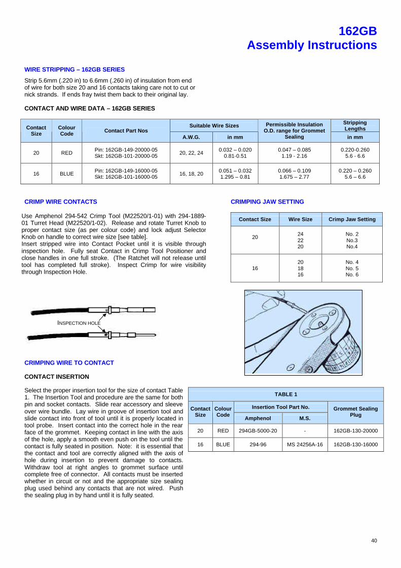
WIRE STRIPPING – 162GB SERIES
Strip 5.6mm (.220 in) to 6.6mm (.260 in) of insulation from end of wire for both size 20 and 16 contacts taking care not to cut or nick strands. If ends fray twist them back to their original lay.
CONTACT AND WIRE DATA – 162GB SERIES
Suitable Wire Sizes Stripping Lengths Contact
Size Colour Code Contact Part Nos
A.W.G. in mm
Permissible Insulation O.D. range for Grommet
Sealing in mm
20 RED Pin: 162GB-149-20000-05 Skt: 162GB-101-20000-05 20, 22, 24 0.032 – 0.020
0.81-0.51 0.047 – 0.085
1.19 - 2.16 0.220-0.260
5.6 - 6.6
16 BLUE Pin: 162GB-149-16000-05 Skt: 162GB-101-16000-05 16, 18, 20 0.051 – 0.032
1.295 – 0.81 0.066 – 0.109 1.675 – 2.77
0.220 – 0.260 5.6 – 6.6
CRIMP WIRE CONTACTS CRIMPING JAW SETTING
Contact Size Wire Size Crimp Jaw Setting
20
24 22 20
No. 2 No.3 No.4
Use Amphenol 294-542 Crimp Tool (M22520/1-01) with 294-1889-01 Turret Head (M22520/1-02). Release and rotate Turret Knob to proper contact size (as per colour code) and lock adjust Selector Knob on handle to correct wire size [see table]. Insert stripped wire into Contact Pocket until it is visible through inspection hole. Fully seat Contact in Crimp Tool Positioner and close handles in one full stroke. (The Ratchet will not release until tool has completed full stroke). Inspect Crimp for wire visibility through Inspection Hole.
16 20 18 16
No. 4 No. 5 No. 6
CRIMPING WIRE TO CONTACT CONTACT INSERTION
TABLE 1
Insertion Tool Part No. Contact Size
Colour Code
Amphenol M.S.
Grommet Sealing Plug
20 RED 294GB-5000-20 - 162GB-130-20000
16 BLUE 294-96 MS 24256A-16 162GB-130-16000
Select the proper insertion tool for the size of contact Table 1. The Insertion Tool and procedure are the same for both pin and socket contacts. Slide rear accessory and sleeve over wire bundle. Lay wire in groove of insertion tool and slide contact into front of tool until it is properly located in tool probe. Insert contact into the correct hole in the rear face of the grommet. Keeping contact in line with the axis of the hole, apply a smooth even push on the tool until the contact is fully seated in position. Note: it is essential that the contact and tool are correctly aligned with the axis of hole during insertion to prevent damage to contacts. Withdraw tool at right angles to grommet surface until complete free of connector. All contacts must be inserted whether in circuit or not and the appropriate size sealing plug used behind any contacts that are not wired. Push the sealing plug in by hand until it is fully seated.
INSPECTION HOLE
41
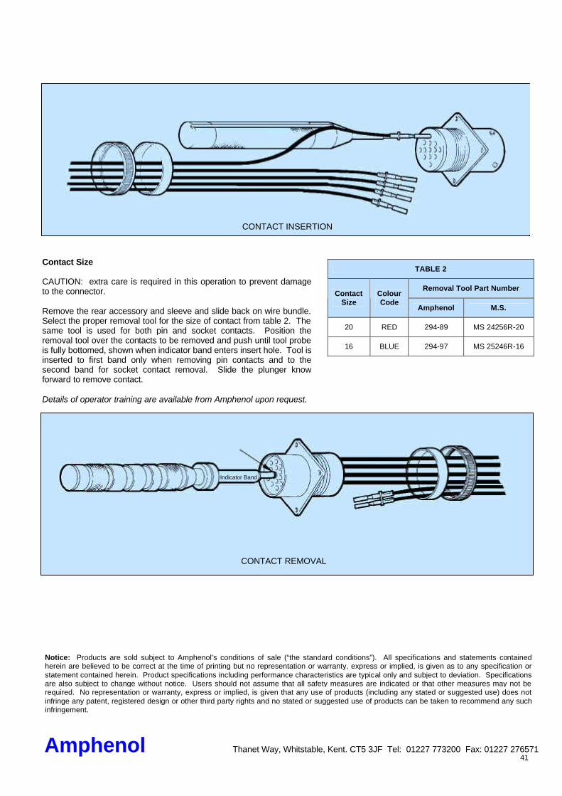
TABLE 2
Removal Tool Part Number Contact
Size Colour Code
Amphenol M.S.
20 RED 294-89 MS 24256R-20
16 BLUE 294-97 MS 25246R-16
Contact Size CAUTION: extra care is required in this operation to prevent damage to the connector. Remove the rear accessory and sleeve and slide back on wire bundle. Select the proper removal tool for the size of contact from table 2. The same tool is used for both pin and socket contacts. Position the removal tool over the contacts to be removed and push until tool probe is fully bottomed, shown when indicator band enters insert hole. Tool is inserted to first band only when removing pin contacts and to the second band for socket contact removal. Slide the plunger know forward to remove contact. Details of operator training are available from Amphenol upon request.
Indicator Band
CONTACT REMOVAL
CONTACT INSERTION
Amphenol Thanet Way, Whitstable, Kent. CT5 3JF Tel: 01227 773200 Fax: 01227 276571
Notice: Products are sold subject to Amphenol’s conditions of sale (“the standard conditions”). All specifications and statements contained herein are believed to be correct at the time of printing but no representation or warranty, express or implied, is given as to any specification or statement contained herein. Product specifications including performance characteristics are typical only and subject to deviation. Specifications are also subject to change without notice. Users should not assume that all safety measures are indicated or that other measures may not be required. No representation or warranty, express or implied, is given that any use of products (including any stated or suggested use) does not infringe any patent, registered design or other third party rights and no stated or suggested use of products can be taken to recommend any such infringement.