Embed Size (px)
Citation preview
Panasonic Subscriber Communicator
KX-G7100/7101
COMMAND SPECIFICATION
Version 1.40
June 2000
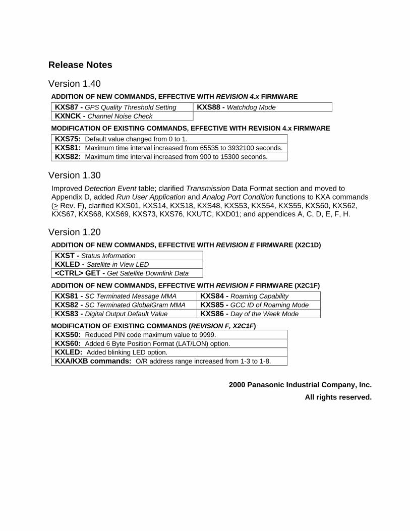
Release Notes
Version 1.40ADDITION OF NEW COMMANDS, EFFECTIVE WITH REVISION 4.x FIRMWARE
KXS87 - GPS Quality Threshold Setting KXS88 - Watchdog ModeKXNCK - Channel Noise Check
MODIFICATION OF EXISTING COMMANDS, EFFECTIVE WITH REVISION 4.x FIRMWARE
KXS75: Default value changed from 0 to 1.KXS81: Maximum time interval increased from 65535 to 3932100 seconds.KXS82: Maximum time interval increased from 900 to 15300 seconds.
Version 1.30Improved Detection Event table; clarified Transmission Data Format section and moved toAppendix D, added Run User Application and Analog Port Condition functions to KXA commands(> Rev. F), clarified KXS01, KXS14, KXS18, KXS48, KXS53, KXS54, KXS55, KXS60, KXS62,KXS67, KXS68, KXS69, KXS73, KXS76, KXUTC, KXD01; and appendices A, C, D, E, F, H.
Version 1.20ADDITION OF NEW COMMANDS, EFFECTIVE WITH REVISION E FIRMWARE (X2C1D)
KXST - Status InformationKXLED - Satellite in View LED<CTRL> GET - Get Satellite Downlink Data
ADDITION OF NEW COMMANDS, EFFECTIVE WITH REVISION F FIRMWARE (X2C1F)
KXS81 - SC Terminated Message MMA KXS84 - Roaming CapabilityKXS82 - SC Terminated GlobalGram MMA KXS85 - GCC ID of Roaming ModeKXS83 - Digital Output Default Value KXS86 - Day of the Week Mode
MODIFICATION OF EXISTING COMMANDS (REVISION F, X2C1F)KXS50: Reduced PIN code maximum value to 9999.KXS60: Added 6 Byte Position Format (LAT/LON) option.KXLED: Added blinking LED option.KXA/KXB commands: O/R address range increased from 1-3 to 1-8.
2000 Panasonic Industrial Company, Inc.
All rights reserved.
Contents - i
Contents
CONTENTS................................................................................................................................................. I
USING THE KX-G7100/ 7101 .................................................................................................................... 1
TRANSMISSION COMMANDS................................................................................................................ 5
Using the Transmission Commands ............................................................................................................... 5KXA01 - Wake at Specified Time(s)............................................................................................................ 12KXA02 - Wake at Time Interval .................................................................................................................. 13KXA03 - Wake Upon Satellite Arrival......................................................................................................... 14KXA04 - Communicate in Byte mode.......................................................................................................... 15KXA05 - Perform Function Upon Port Condition Change ............................................................................ 16KXA06 - Perform Function Immediately ..................................................................................................... 17KXA00 - View Status/Deactivate All KXA Commands ............................................................................... 18
TRACKING COMMANDS ...................................................................................................................... 19
Using the Tracking Commands .................................................................................................................... 20Restrictions.................................................................................................................................................. 20KXB01 - Wake at Specified Time(s)............................................................................................................ 26KXB02 - Wake at Time Interval .................................................................................................................. 27KXB03 - Wake Upon Satellite Arrival ......................................................................................................... 28KXB00 - View Status/Deactivate All KXB Commands................................................................................ 29
SET-UP COMMANDS.............................................................................................................................. 31
Using the Set-Up Commands....................................................................................................................... 31KXS01 - Network Control Center ID ........................................................................................................... 32KXS02 - Polling Parameter.......................................................................................................................... 33KXS03 - Default Message Priority............................................................................................................... 34KXS04 - Default Report Recipient............................................................................................................... 35KXS05 - Default Message/GlobalGram Recipient........................................................................................ 36KXS06 - Acknowledgment Level ................................................................................................................ 37KXS07 - Default Message Body Type ......................................................................................................... 38KXS08 - Default Service Type..................................................................................................................... 39KXS09 - [Reserved] .................................................................................................................................... 40KXS10 - Report Interval .............................................................................................................................. 41KXS11 - Number Of Reports To Be Transmitted ......................................................................................... 42KXS12 - Position Report Interval................................................................................................................ 43KXS13 - Number Of Position Reports To Be Transmitted............................................................................ 44KXS14 - Gateway (GWY) Search Mode...................................................................................................... 45KXS15 - Priority Search List For Downlink................................................................................................. 46KXS16 - Packet Error Acceptance Level...................................................................................................... 47
Contents - ii
KXS17 - Checksum Frame Count ................................................................................................................ 48KXS18 - Continuous Position Determination ............................................................................................... 49KXS19 - Data Collection Period / Sample Points ......................................................................................... 50KXS20 - Position Data Age Limit................................................................................................................ 51KXS21 - Minimum Quality Indicator for Doppler Positioning...................................................................... 52KXS22 - Maximum Age of Orbital Elements ............................................................................................... 53KXS23 - Set Latitude / Longitude ................................................................................................................ 54KXS24 - Internal Position Calculation ......................................................................................................... 55KXS25 - GPS Data Format .......................................................................................................................... 56KXS26 - Data Response Timeout................................................................................................................. 57KXS27 - Serial Packet Acknowledgment Timeout ....................................................................................... 58KXS28 - Maximum Retries to DTE ............................................................................................................. 59KXS29 - Abort Response to NCC................................................................................................................ 60KXS30 - Abort Report................................................................................................................................. 61KXS31 - Operation Mode ............................................................................................................................ 62KXS32 - Byte Mode Trigger........................................................................................................................ 63KXS33 - Byte Mode Timeout ...................................................................................................................... 64KXS34 - Byte Mode Length ........................................................................................................................ 65KXS35 - Byte Mode TX SOM/EOM / RX SOM/EOM ................................................................................ 66KXS36 - Byte Mode Message Type ............................................................................................................. 67KXS37 - Power Down Mode ....................................................................................................................... 68KXS38 - Minimum Power Down Interval .................................................................................................... 69KXS39 - Inactive Interval ............................................................................................................................ 70KXS40 - Power Save Mode ......................................................................................................................... 71KXS41 - Inbound Flow Control ................................................................................................................... 72KXS42 - Outbound Flow Control................................................................................................................. 73KXS43 - RS232C Mode .............................................................................................................................. 74KXS44 - Duplex Switch .............................................................................................................................. 75KXS45 - Inbound Message Treatment.......................................................................................................... 76KXS46 - Outbound Message Treatment ....................................................................................................... 77KXS47 - Save Inbound Message.................................................................................................................. 78KXS48 - Inbound / Outbound Queue Size.................................................................................................... 79KXS49 - UTC Time Adjust ......................................................................................................................... 80KXS50 - PIN Code ...................................................................................................................................... 81KXS51 - Automatic GlobalGram Polling ..................................................................................................... 82KXS52 - GPS Datum Select......................................................................................................................... 83KXS53 - RTS Logic Setting......................................................................................................................... 84KXS54 - Output Pulse Mode Setting (KX-G7101 only) ............................................................................... 85KXS55 - Analog Port Select ........................................................................................................................ 86KXS56 - Distance Select.............................................................................................................................. 87KXS57 - Area Select.................................................................................................................................... 88KXS58 - Speed Select.................................................................................................................................. 89KXS59 - Send Transmission Log to DTE..................................................................................................... 90KXS60 - Data Format .................................................................................................................................. 91KXS61 - RS232 Driver Auto Shut Down ..................................................................................................... 92KXS62 - GPS Output Pulse Error Message .................................................................................................. 93KXS63 - Time Window ............................................................................................................................... 94KXS64 - Quick Power Down....................................................................................................................... 95KXS65 - Position Transmission Mode ......................................................................................................... 96KXS66 - RAM Manager .............................................................................................................................. 97KXS67 - User Application Program Auto-Start............................................................................................ 98
Contents - iii
KXS68 - Serial Port Settings........................................................................................................................ 99KXS69 - Outbound Data Route Management............................................................................................. 100KXS70 - User Application Debug Mode .................................................................................................... 101KXS71 - Remote Configuration Password ................................................................................................. 102KXS72 - Echo Remote Command Response .............................................................................................. 103KXS73 - [Reserved] .................................................................................................................................. 104KXS74 - Message Transmission Mode....................................................................................................... 105KXS75 - Message Type Auto Change........................................................................................................ 106KXS76 - Satellite Elevation ....................................................................................................................... 107KXS77 - Message Body Transmission in Byte Mode ................................................................................. 108KXS78 - Buffer Full Message.................................................................................................................... 110KXS79 - Event Timer ................................................................................................................................ 111KXS80 - GlobalGram Message Format...................................................................................................... 112KXS81 - SC Terminated Message MMA (Maximum MSN Age) ............................................................... 113KXS82 - SC Terminated GlobalGram MMA (Maximum MSN Age).......................................................... 114KXS83 - Digital Output Default Value....................................................................................................... 115KXS84 - Roaming Capability .................................................................................................................... 116KXS85 - GCC ID of Roaming Mode ......................................................................................................... 117KXS86 - Day of the Week Mode ............................................................................................................... 118KXS87 - GPS Quality Threshold ............................................................................................................... 119KXS88 - Watchdog Mode.......................................................................................................................... 120KXS00 - Get Values of All KXS Parameters.............................................................................................. 121
SPECIAL COMMANDS......................................................................................................................... 122
KXM01 - Fixed Message........................................................................................................................... 122KXD01 - Output Port State ........................................................................................................................ 123KXD02 - Get Analog Port Value ............................................................................................................... 124KXCB - Clear Transmission Log for DTE ................................................................................................. 125KXP01 - I/O Port Linkage ......................................................................................................................... 126KXIB - Clear Inbound Queue of SC........................................................................................................... 127KXOB - Clear Outbound Queue of SC....................................................................................................... 128KXUTC - Check/Set Internal Clock........................................................................................................... 129KXCHK - System Diagnosis Test .............................................................................................................. 130KXST - Status Information ........................................................................................................................ 131KXLED - Satellite in View LED................................................................................................................ 132GET - Get Satellite Downlink Data............................................................................................................ 133KXNCK - Channel Noise Check................................................................................................................ 134Default Configuration ................................................................................................................................ 135Default Baud Rate ..................................................................................................................................... 136
APPENDICES ......................................................................................................................................... 137
Appendix A: Understanding the Modes of Operation ................................................................................. 137Appendix B: Byte Mode Operations .......................................................................................................... 138Appendix C: ASCII Character Table.......................................................................................................... 139Appendix D: Transmission Data Format .................................................................................................... 142Appendix E: Function / Parameter Setting Matrix ...................................................................................... 148Appendix F: Power On – Off ..................................................................................................................... 153Appendix G: Serial Interface...................................................................................................................... 155Appendix H: GPS Datum Table ................................................................................................................. 157
DEFINITIONS OF KEY TERMS .......................................................................................................... 160
Using the KX-G7100/7101 - 1
Using The KX-G7100/ 7101
INTRODUCTIONThere are two ways to communicate with the Panasonic KX-G7100/7101 Subscriber Communicator(SC). The SC can be connected to a PC or DTE via its built-in RS-232 serial port, or can be accessedindirectly through the ORBCOMM system (remote PC/DTE to satellite to SC, referred to as "HOST"from here on in).
Further, the KX-G7100/7101 is configured for operation with two command sets: the defaultORBCOMM command set, and the Panasonic command set.
The ORBCOMM Command SetThe ORBCOMM command set uses two serial port interface modes for communication: the primaryProtocol mode, and Byte mode .
Protocol modeIn Protocol mode, the communication between SC and DTE is based in the Serial InterfaceSpecification as prepared by ORBCOMM. The DTE can send and receive messages, reports,commands and "GlobalGrams", as well as obtain time-of-day and position estimates.
This is the SC's default mode of operation. If desired, the default can be changed to Byte Mode usingKXS31 (Operation Mode).
Byte modeByte mode is used primarily for direct-connection communication between the SC and PC/DTE. Inthis mode, data bytes are generated without header, length field, or checksum information, allowing amore efficient transfer of large messages. However, the transfers are less robust due to the lack ofacknowledgements and checksums.
Configuring the SC to identify Byte mode data can be done by configuring these Panasoniccommands: KXS32 (Byte Mode Trigger), KXS33 (Byte Mode Timeout), KXS34 (Byte Mode Length),KXS35 (Byte Mode TX SOM/EOM, RX SOM/EOM).
Using the KX-G7100/7101 - 2
The Panasonic Command SetThe Panasonic command set is divided into four subsets, each having its own section in this manual:
• Transmission Commands
• Tracking Function Commands
• Setup Commands
• Special Commands
Accessing the Panasonic Command SetThe KX-G7100/7101 uses an on-board command interpreter, allowing you to see immediate results ofchanges made to any command parameters on the PC/DTE screen. If using a PC, you must havecommunication software (i.e. HyperTerminal or equivalent, set at 4800/8/None/1, Flow Control OFF)and an RS-232 serial (modem) cable for connecting the SC to the PC. To access the SC and use thePanasonic commands, enter the following:
CTRL + K X O R B(Hold the CONTROL key down while typing the ‘K X O R B’ characters.)The PC/DTE will acknowledge with the SC's serial number and the right chevron ( > ) commandprompt.
To exit the Panasonic command set, enter CTRL + Q.If no command is entered after 5 minutes, the SC will default back to the ORBCOMM command set.
Inputting the Panasonic CommandsAll Panasonic commands are input in UPPER CASE. Commands begin with the letters ‘KX’ and endwith <Enter> or equivalent (<Return>, <CR>, <CR><LF>). Command parameters or variables areseparated by a comma ( , ). These commands are available in both PC/DTE and HOST operation.
Sending CommandsFrom the PC or DTE:• Change to command mode (type <CTRL> KXORB).
• Send only ONE command at a time.
• Wait for the “>” prompt from the SC before sending additional commands.
From the HOST (remote):
• Message must be placed in the email message body (not in the subject line).
• The first character of message must be “$”.
• The maximum size of the message is 180 characters.
• After each command, press the <Enter> or <Return> key. On some DTEs, it may be necessary touse <CR>, <LF>, or both <CR> and <LF>. (<CR> is 0x0d, and <LF> is 0x0a.)
Example: To set the Acknowledgement Level (KXS06) and Transmission mode (KXA05), type:
$KXS06=1 <Return>KXA05=0,1,2,3 <Return>
Using the KX-G7100/7101 - 3
Remote Configuration Password
To prevent tampering and assure security, a remote configuration password can be assigned usingKXS71 (Remote Configuration Password). The password must be appended to the appropriateSetup, Transmission or Tracking command in order to allow remote configuration changes.
By default, KXS71 is set to "0000", meaning no password is active and therefore not needed in themessage body. Assigning a value to KXS71 activates the password and mandates its use in themessage. Furthermore, assigning a value to KXS71 also serves to activate an inherent, secondarypassword: The last four digits of the SC's serial number. Either can be used when KXS71 is set.
Example: To configure KXS06 and KXA05 when KXS71=AZ90.
$KXS06=1 <Return>KXA05=0,1,2,3 <Return>PW=AZ90 <Return>
Another use of the password feature is Group Configuration. To configure a group of SCs, set KXS71to the same value on each SC in the group.
Command Response MessageAfter a KX command is sent, an ACK or NACK response message is received from the SC.
<ACK> MessageWhen a command has been sent successfully, the SC responds by echoing the message that wassent.
For example, the command “ KXA06=2,1 <Return>” would be followed by “ KXA06 = 2,1.”
<NACK> MessageWhen a command is unsuccessful, one of the following error messages will be received.
• ERR0 –Parameter error (the parameter is beyond the minimum or maximum permissiblevalue), or Command not defined (command does not exist).
• ERR1 – Exclusive control error (two or more settings conflict).• ERR2 – Response message not created. During a remote configuration session, If the
receive buffer is full, the SC will send this error message to the HOST.
Except in the case of ERR2, command responses from a remote configuration session are not echoedback to the PC/DTE. If confirmation via email is desired, KXS72 (Echo Remote Command Response)can be set to see the echoed responses from each entered command.
Please note that ONLY the default O/R recipient set by KXS05 can receive the echoed responses.

Transmission Commands - 5
Transmission Commands
Using the Transmission Commands
The Panasonic Transmission Commands can be thought of as macro commands. The TransmissionCommand set is designed to allow a user to quickly and easily design and implement an application.
Restrictions on Selection
KXA01 - KXA04 commands:Only one command can be active at a given time.
Example: If KXA01 is active and the user inputs the KXA02 command, the KXA01 command will becanceled.
KXA05 and KXA06 commands:KXA05 can be active at the same time other commands are active. KXA06 can always be used,regardless of the transmission commands typed in.
Transmission Commands - 6
Automatic Power-Down(See flowchart in Appendix F for more detail)
KXA01 - KXA03 commands:When the KXA01, KXA02 or KXA03 commands are entered, the Power Down mode will beautomatically activated (KXS37=1, Power Down mode - On). At the start of the specified function, theSC will power on automatically and stay awake for a specified interval, in order to send data.
To prevent the SC from sleeping while using KXA01, KXA02 or KXA03, disablethe automatic Power Down mode. Configure set-up command KXS37=0 (PowerDown Mode - Off).
KXA04 or KXA05 commands:
KXA04 or KXA05 will automatically disable the Power Down mode (KXS37=0 Power Down Mode -Off)
To power off automatically when either KXA04 or KXA05 is active, use KXS37=1(Power Down Mode - On), or use the remote control lines.
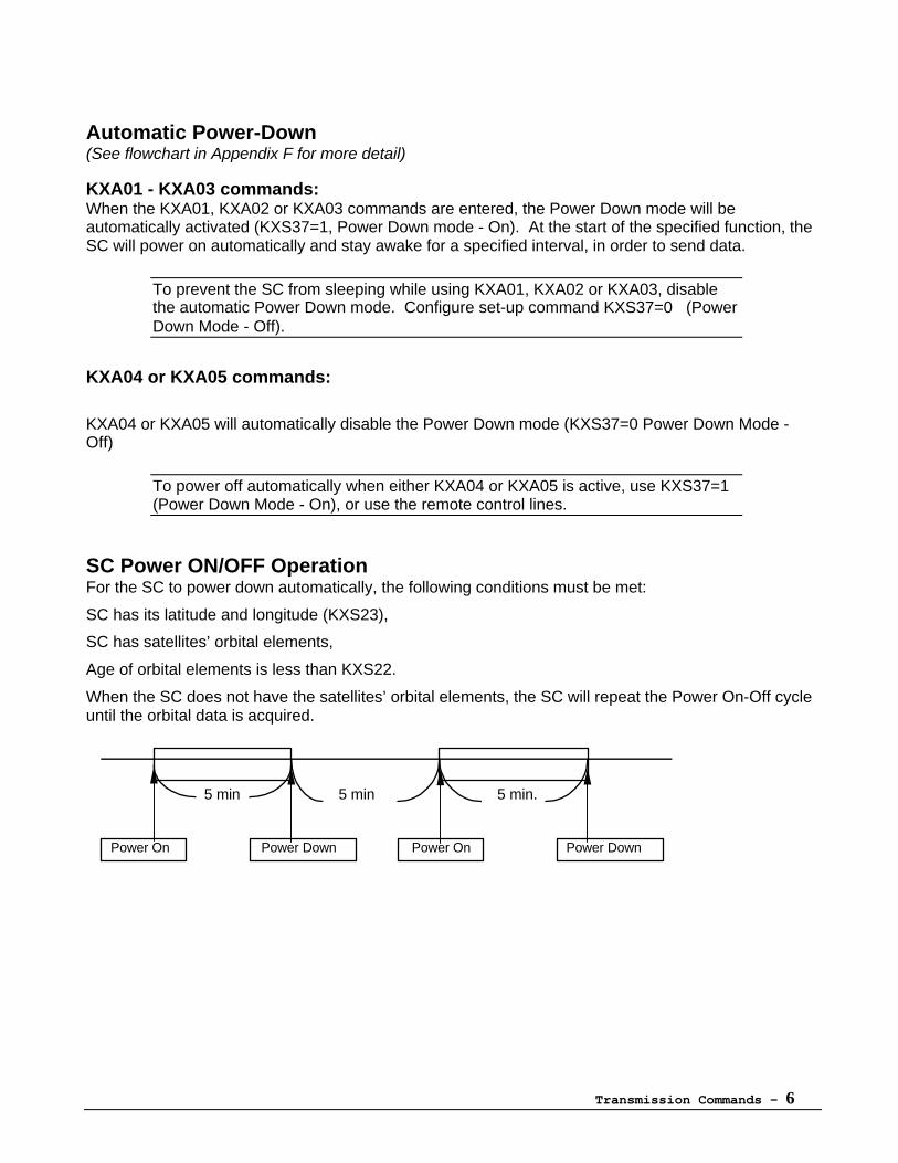
SC Power ON/OFF OperationFor the SC to power down automatically, the following conditions must be met:
SC has its latitude and longitude (KXS23),
SC has satellites’ orbital elements,
Age of orbital elements is less than KXS22.
When the SC does not have the satellites’ orbital elements, the SC will repeat the Power On-Off cycleuntil the orbital data is acquired.
5 min 5 min 5 min.
Power On Power Down Power On Power Down
Transmission Commands - 7
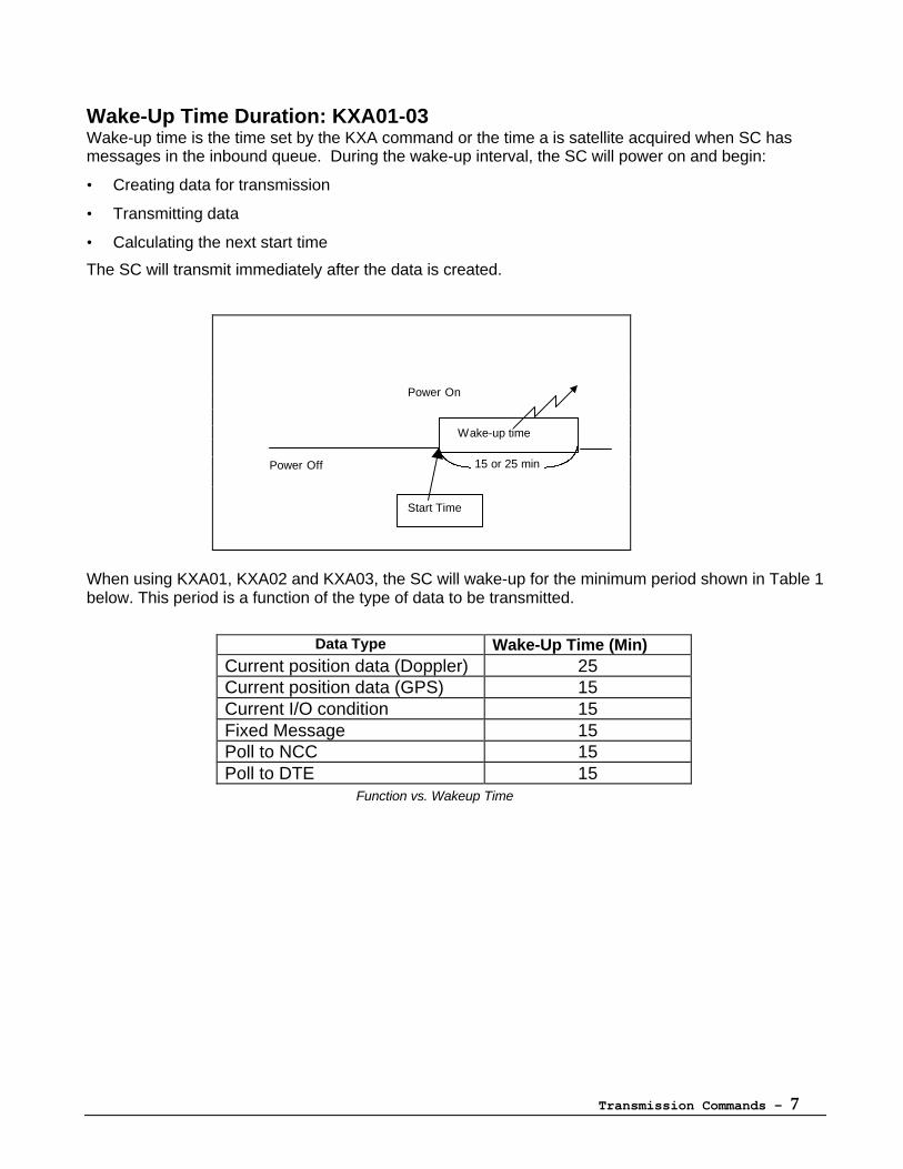
Wake-Up Time Duration: KXA01-03Wake-up time is the time set by the KXA command or the time a is satellite acquired when SC hasmessages in the inbound queue. During the wake-up interval, the SC will power on and begin:
• Creating data for transmission
• Transmitting data
• Calculating the next start time
The SC will transmit immediately after the data is created.
When using KXA01, KXA02 and KXA03, the SC will wake-up for the minimum period shown in Table 1below. This period is a function of the type of data to be transmitted.
Data Type Wake-Up Time (Min)Current position data (Doppler) 25Current position data (GPS) 15Current I/O condition 15Fixed Message 15Poll to NCC 15Poll to DTE 15
Function vs. Wakeup Time
Wake-up time
15 or 25 min
Start Time
Power Off
Power On
Transmission Commands - 8
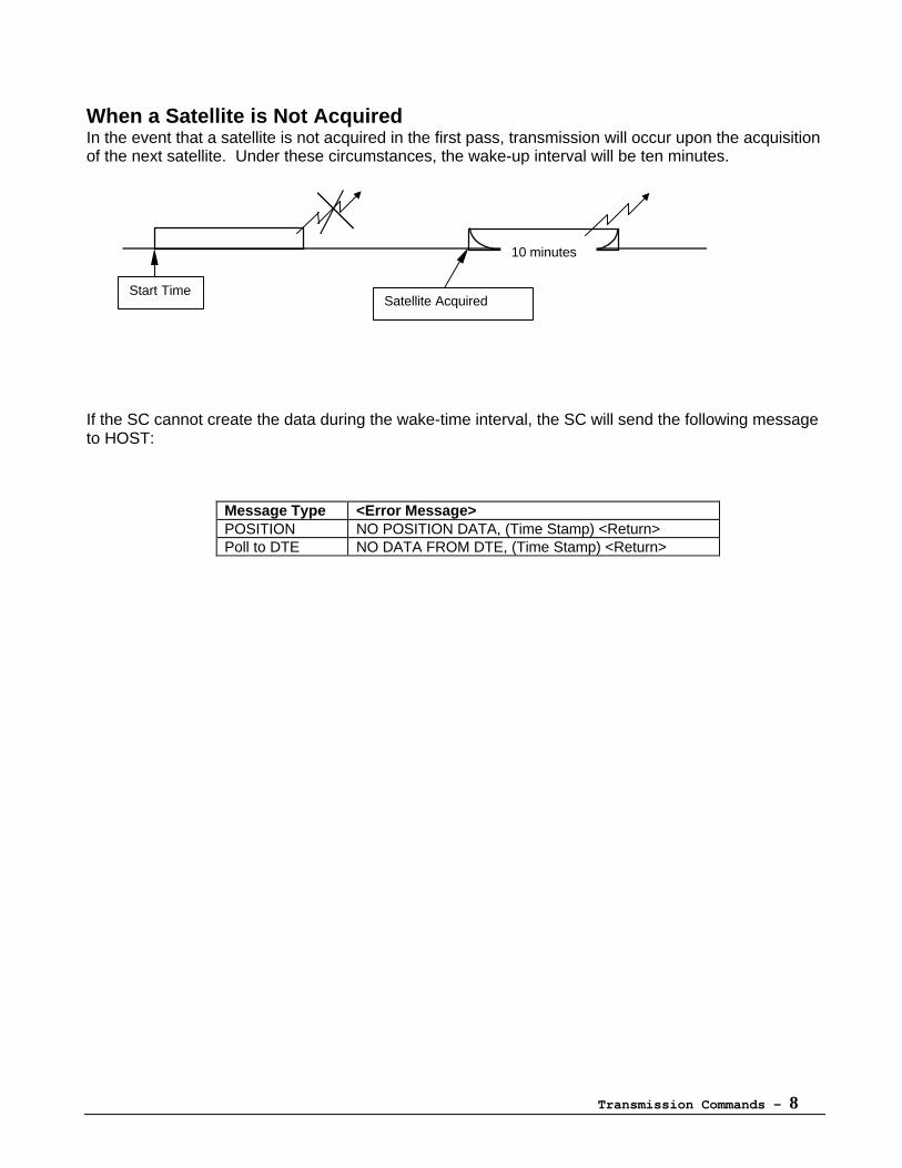
When a Satellite is Not AcquiredIn the event that a satellite is not acquired in the first pass, transmission will occur upon the acquisitionof the next satellite. Under these circumstances, the wake-up interval will be ten minutes.
If the SC cannot create the data during the wake-time interval, the SC will send the following messageto HOST:
Message Type <Error Message>POSITION NO POSITION DATA, (Time Stamp) <Return>Poll to DTE NO DATA FROM DTE, (Time Stamp) <Return>
Satellite AcquiredStart Time
10 minutes
Transmission Commands - 9
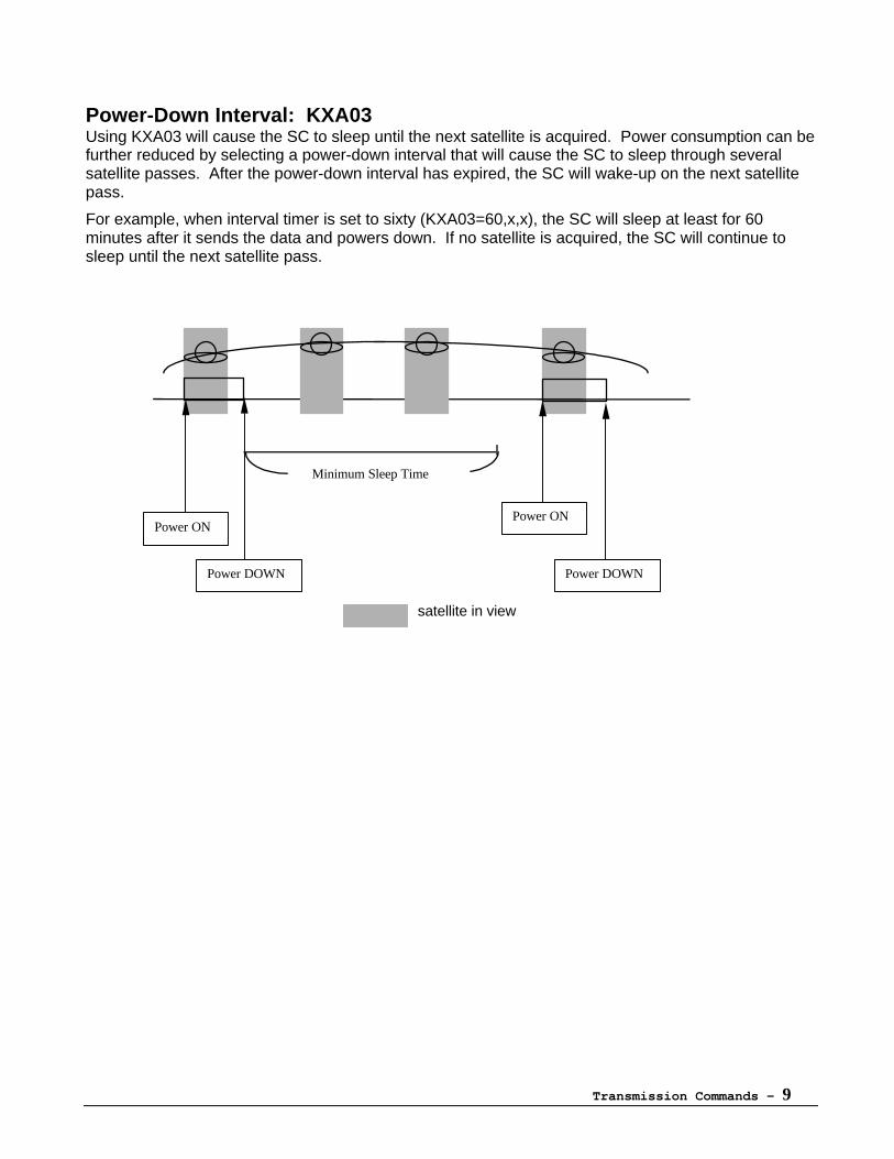
Power-Down Interval: KXA03Using KXA03 will cause the SC to sleep until the next satellite is acquired. Power consumption can befurther reduced by selecting a power-down interval that will cause the SC to sleep through severalsatellite passes. After the power-down interval has expired, the SC will wake-up on the next satellitepass.
For example, when interval timer is set to sixty (KXA03=60,x,x), the SC will sleep at least for 60minutes after it sends the data and powers down. If no satellite is acquired, the SC will continue tosleep until the next satellite pass.
satellite in view
Power ONPower ON
Power DOWN Power DOWN
Minimum Sleep Time
Transmission Commands - 10
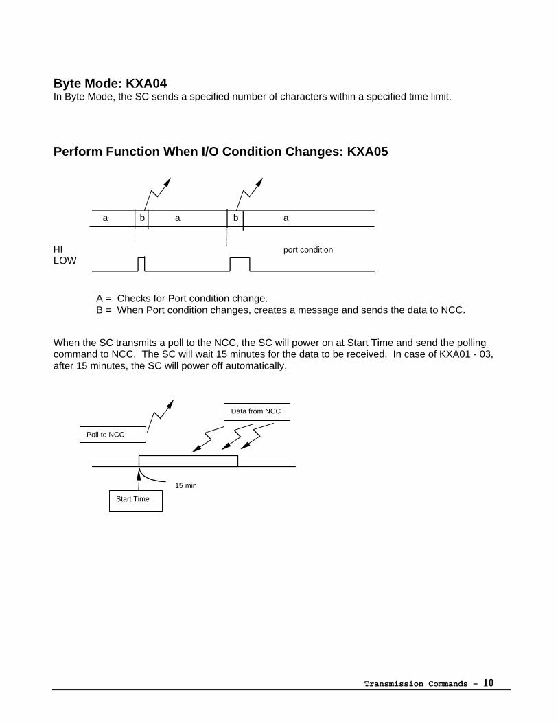
Byte Mode: KXA04In Byte Mode, the SC sends a specified number of characters within a specified time limit.
Perform Function When I/O Condition Changes: KXA05
a b a b a
HI port conditionLOW
A = Checks for Port condition change.B = When Port condition changes, creates a message and sends the data to NCC.
When the SC transmits a poll to the NCC, the SC will power on at Start Time and send the pollingcommand to NCC. The SC will wait 15 minutes for the data to be received. In case of KXA01 - 03,after 15 minutes, the SC will power off automatically.
Data from NCC
Poll to NCC
Start Time
15 min
Transmission Commands - 11
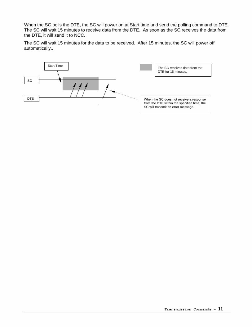
When the SC polls the DTE, the SC will power on at Start time and send the polling command to DTE.The SC will wait 15 minutes to receive data from the DTE. As soon as the SC receives the data fromthe DTE, it will send it to NCC.
The SC will wait 15 minutes for the data to be received. After 15 minutes, the SC will power offautomatically..
.
The SC receives data from theDTE for 15 minutes.
Start Time
DTE When the SC does not receive a responsefrom the DTE within the specified time, theSC will transmit an error message.
SC
Transmission Commands - 12
KXA01 - Wake at Specified Time(s)
Wake at a specified time, perform assigned functions, and transmit.
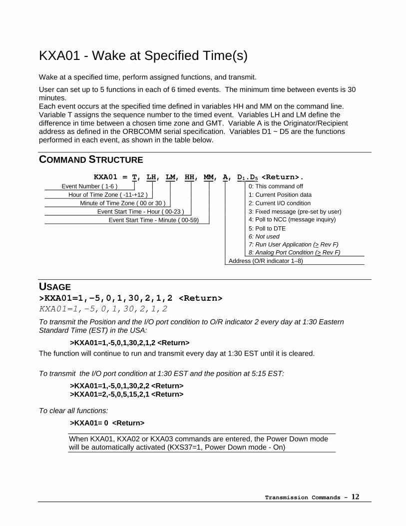
User can set up to 5 functions in each of 6 timed events. The minimum time between events is 30minutes.Each event occurs at the specified time defined in variables HH and MM on the command line.Variable T assigns the sequence number to the timed event. Variables LH and LM define thedifference in time between a chosen time zone and GMT. Variable A is the Originator/Recipientaddress as defined in the ORBCOMM serial specification. Variables D1 ~ D5 are the functionsperformed in each event, as shown in the table below.
COMMAND STRUCTURE
KXA01 = T, LH, LM, HH, MM, A, D1.D5 <Return>.Event Number ( 1-6 ) 0: This command off
Hour of Time Zone ( -11-+12 ) 1: Current Position data Minute of Time Zone ( 00 or 30 ) 2: Current I/O condition Event Start Time - Hour ( 00-23 ) 3: Fixed message (pre-set by user)
Event Start Time - Minute ( 00-59) 4: Poll to NCC (message inquiry)
5: Poll to DTE6: Not used7: Run User Application (> Rev F)8: Analog Port Condition (> Rev F)
Address (O/R indicator 1–8)
USAGE>KXA01=1,-5,0,1,30,2,1,2 <Return>KXA01=1,-5,0,1,30,2,1,2
To transmit the Position and the I/O port condition to O/R indicator 2 every day at 1:30 EasternStandard Time (EST) in the USA:
>KXA01=1,-5,0,1,30,2,1,2 <Return>The function will continue to run and transmit every day at 1:30 EST until it is cleared.
To transmit the I/O port condition at 1:30 EST and the position at 5:15 EST:
>KXA01=1,-5,0,1,30,2,2 <Return>>KXA01=2,-5,0,5,15,2,1 <Return>
To clear all functions:
>KXA01= 0 <Return>
When KXA01, KXA02 or KXA03 commands are entered, the Power Down modewill be automatically activated (KXS37=1, Power Down mode - On)
Transmission Commands - 13
KXA02 - Wake at Time Interval
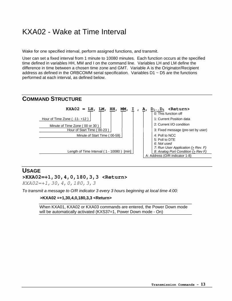
Wake for one specified interval, perform assigned functions, and transmit.
User can set a fixed interval from 1 minute to 10080 minutes. Each function occurs at the specifiedtime defined in variables HH, MM and I on the command line. Variables LH and LM define thedifference in time between a chosen time zone and GMT. Variable A is the Originator/Recipientaddress as defined in the ORBCOMM serial specification. Variables D1 ~ D5 are the functionsperformed at each interval, as defined below.
COMMAND STRUCTURE
KXA02 = LH, LM, HH, MM, I , A, D1-.D5 <Return>0: This function off
Hour of Time Zone ( -11- +12 ) 1: Current Position data
Minute of Time Zone ( 00 or 30 ) 2: Current I/O condition
Hour of Start Time ( 00-23 ) 3: Fixed message (pre-set by user)
Minute of Start Time ( 00-59) 4: Poll to NCC
Length of Time Interval ( 1 - 10080 ) [min]
5: Poll to DTE6: Not used7: Run User Application (> Rev. F)8: Analog Port Condition (> Rev F)
A: Address (O/R indicator 1-8)
USAGE>KXA02=+1,30,4,0,180,3,3 <Return>KXA02=+1,30,4,0,180,3,3
To transmit a message to O/R indicator 3 every 3 hours beginning at local time 4:00:
>KXA02 =+1,30,4,0,180,3,3 <Return>
When KXA01, KXA02 or KXA03 commands are entered, the Power Down modewill be automatically activated (KXS37=1, Power Down mode - On)
Transmission Commands - 14
KXA03 - Wake Upon Satellite Arrival
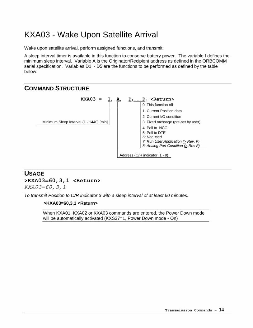
Wake upon satellite arrival, perform assigned functions, and transmit.
A sleep interval timer is available in this function to conserve battery power. The variable I defines theminimum sleep interval. Variable A is the Originator/Recipient address as defined in the ORBCOMMserial specification. Variables D1 ~ D5 are the functions to be performed as defined by the tablebelow.
COMMAND STRUCTURE
KXA03 = I, A, D1...D5 <Return>0: This function off
1: Current Position data
2: Current I/O conditionMinimum Sleep Interval (1 - 1440) [min] 3: Fixed message (pre-set by user)
4: Poll to NCC5: Poll to DTE6: Not used7: Run User Application (> Rev. F)8: Analog Port Condition (> Rev F)
Address (O/R indicator 1 - 8)
USAGE>KXA03=60,3,1 <Return>KXA03=60,3,1
To transmit Position to O/R indicator 3 with a sleep interval of at least 60 minutes:
>KXA03=60,3,1 <Return>
When KXA01, KXA02 or KXA03 commands are entered, the Power Down modewill be automatically activated (KXS37=1, Power Down mode - On)
Transmission Commands - 15
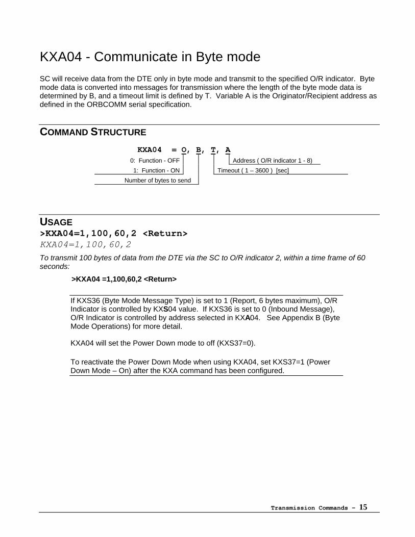
KXA04 - Communicate in Byte mode
SC will receive data from the DTE only in byte mode and transmit to the specified O/R indicator. Bytemode data is converted into messages for transmission where the length of the byte mode data isdetermined by B, and a timeout limit is defined by T. Variable A is the Originator/Recipient address asdefined in the ORBCOMM serial specification.
COMMAND STRUCTURE
KXA04 = O, B, T, A 0: Function - OFF Address ( O/R indicator 1 - 8)
1: Function - ON Timeout ( 1 – 3600 ) [sec]
Number of bytes to send
USAGE>KXA04=1,100,60,2 <Return>KXA04=1,100,60,2
To transmit 100 bytes of data from the DTE via the SC to O/R indicator 2, within a time frame of 60seconds:
>KXA04 =1,100,60,2 <Return>
If KXS36 (Byte Mode Message Type) is set to 1 (Report, 6 bytes maximum), O/RIndicator is controlled by KXS04 value. If KXS36 is set to 0 (Inbound Message),O/R Indicator is controlled by address selected in KXA04. See Appendix B (ByteMode Operations) for more detail.
KXA04 will set the Power Down mode to off (KXS37=0).
To reactivate the Power Down Mode when using KXA04, set KXS37=1 (PowerDown Mode – On) after the KXA command has been configured.
Transmission Commands - 16
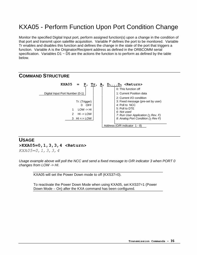
KXA05 - Perform Function Upon Port Condition Change
Monitor the specified Digital Input port, perform assigned function(s) upon a change in the condition ofthat port and transmit upon satellite acquisition. Variable P defines the port to be monitored. VariableTr enables and disables this function and defines the change in the state of the port that triggers afunction. Variable A is the Originator/Recipient address as defined in the ORBCOMM serialspecification. Variables D1 ~ D5 are the actions the function is to perform as defined by the tablebelow.
COMMAND STRUCTURE
KXA05 = P, Tr, A, D1...D5 <Return>0: This function off
Digital Input Port Number (0-1) 1: Current Position data
2: Current I/O conditionTr: (Trigger) 3: Fixed message (pre-set by user)
0 OFF 4: Poll to NCC
1 LOW -> HI
2 HI -> LOW
3 HI <-> LOW
5: Poll to DTE6: Not used7: Run User Application (> Rev. F)8: Analog Port Condition (> Rev F)
Address (O/R indicator 1 - 8)
USAGE>KXA05=0,1,3,3,4 <Return>KXA05=0,1,3,3,4
Usage example above will poll the NCC and send a fixed message to O/R indicator 3 when PORT 0changes from LOW -> HI.
KXA05 will set the Power Down mode to off (KXS37=0).
To reactivate the Power Down Mode when using KXA05, set KXS37=1 (PowerDown Mode – On) after the KXA command has been configured.
Transmission Commands - 17
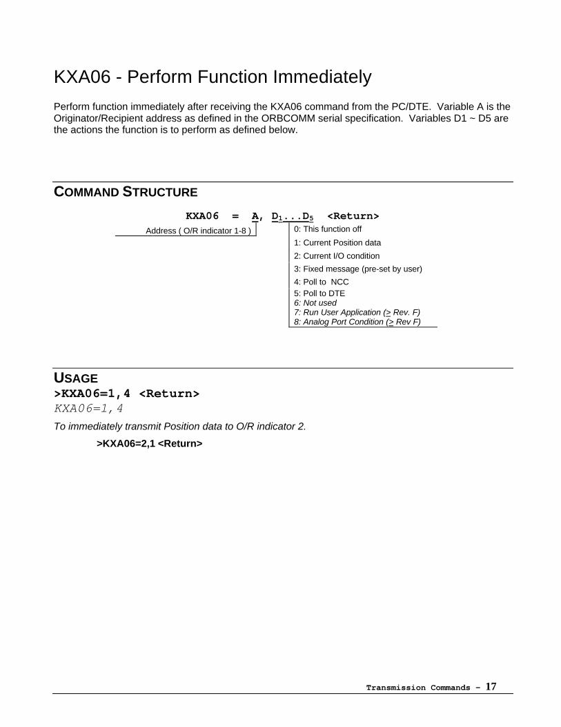
KXA06 - Perform Function Immediately
Perform function immediately after receiving the KXA06 command from the PC/DTE. Variable A is theOriginator/Recipient address as defined in the ORBCOMM serial specification. Variables D1 ~ D5 arethe actions the function is to perform as defined below.
COMMAND STRUCTURE
KXA06 = A, D1...D5 <Return>
Address ( O/R indicator 1-8 ) 0: This function off
1: Current Position data
2: Current I/O condition
3: Fixed message (pre-set by user)
4: Poll to NCC5: Poll to DTE6: Not used7: Run User Application (> Rev. F)8: Analog Port Condition (> Rev F)
USAGE>KXA06=1,4 <Return>KXA06=1,4
To immediately transmit Position data to O/R indicator 2.
>KXA06=2,1 <Return>
Transmission Commands - 18
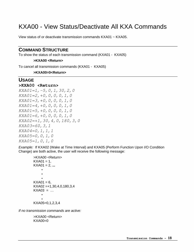
KXA00 - View Status/Deactivate All KXA Commands
View status of or deactivate transmission commands KXA01 ~ KXA05.
COMMAND STRUCTURETo show the status of each transmission command (KXA01 - KXA05)
>KXA00 <Return>
To cancel all transmission commands (KXA01 - KXA05)
>KXA00=0<Return>
USAGE>KXA00 <Return>KXA01=1,-5,0,1,30,2,0KXA01=2,+0,0,0,0,1,0KXA01=3,+0,0,0,0,1,0KXA01=4,+0,0,0,0,1,0KXA01=5,+0,0,0,0,1,0KXA01=6,+0,0,0,0,1,0KXA02=+1,30,4,0,180,3,0KXA03=60,3,1KXA04=0,1,1,1KXA05=0,0,1,0KXA05=1,0,1,0
Example: If KXA02 (Wake at Time Interval) and KXA05 (Perform Function Upon I/O ConditionChange) are both active, the user will receive the following message:
>KXA00 <Return>KXA01 = 1,KXA01 = 2, ...
•••
KXA01 = 6, KXA02 =+1,30,4,0,180,3,4KXA03 = …
••
KXA05=0,1,2,3,4
If no transmission commands are active:
>KXA00 <Return>KXA00=0
Tracking Commands - 19
Tracking Commands
COMMAND NAMESKXB01 = Wake up at a specified time, wait for a designated event, perform assigned functions,and transmit.
KXB02 = Wake up for one specified interval, start observation of event, perform assignedfunctions, and transmit when event meets the assigned condition.
KXB03 = Wake up upon satellite arrival, start observation of event, perform assigned functions,and transmit.
COMMAND DESCRIPTION
The Tracking Commands, also known as KXB commands, are a superset of the TransmissionCommands and are unique to the KX-G7100/7101 series SCs. These commands reduce powerconsumption and have increased functionality. Each of the Tracking Commands will conditionallyperform a specified function and transmit upon satellite availability. To conserve power, thecommunicator will enter sleep mode between satellite passes.
Conditions are sampled during a period called the Observation Period.
Tracking Commands - 20
Using the Tracking Commands
RestrictionsTracking Commands CANNOT be used in conjunction with other Tracking Commands. For example: KXB02CANNOT be enabled when KXB01 is active.
In addition, the Tracking Commands CANNOT be used in conjunction with the Transmission CommandsKXA01 ~ KXA04.
Tracking Command FunctionsSeven functions are available when using Tracking Commands. Functions may be used individually ortogether. If required, all seven functions may be used in any of the Tracking Commands. The sevenfunctions are as follows:
1. Current Position Data2. Current Digital I/O3. Fixed Message4. Poll NCC5. Poll DTE6. Run User Application7. Current Analog Port
(For more information on the Tracking Command Functions, see Appendix D: Transmission DataFormat.)
Tracking Command ConditionsFour basic conditions are available for use with the Tracking Commands.
• Distance• Speed• Area In• Area Out
Each condition is configured using the appropriate Set-up command.
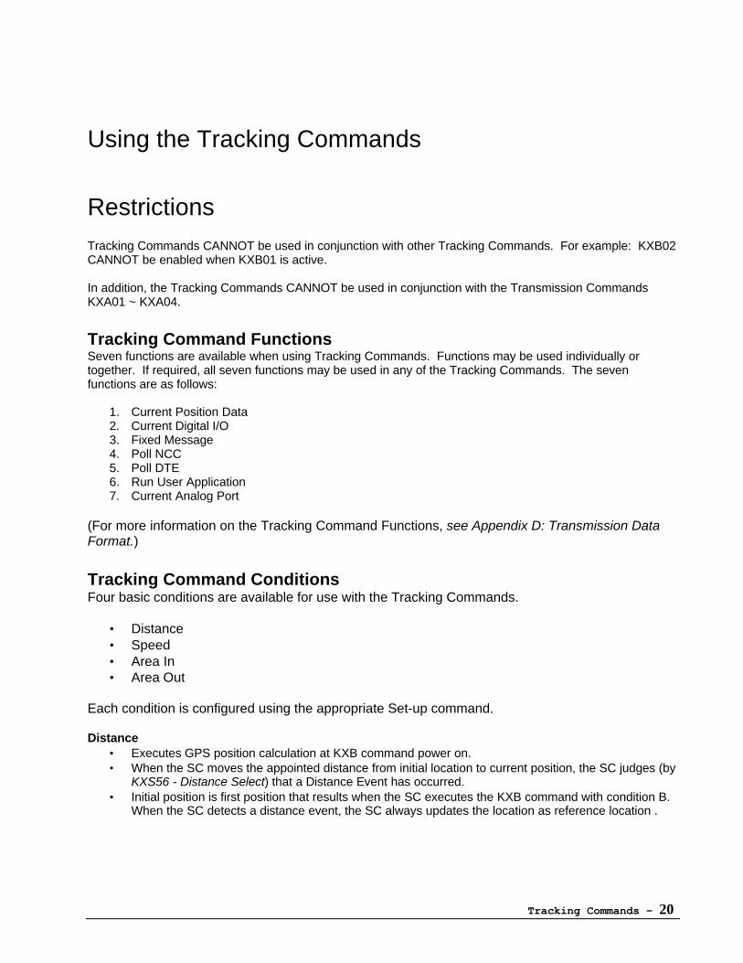
Distance• Executes GPS position calculation at KXB command power on.• When the SC moves the appointed distance from initial location to current position, the SC judges (by
KXS56 - Distance Select) that a Distance Event has occurred.• Initial position is first position that results when the SC executes the KXB command with condition B.
When the SC detects a distance event, the SC always updates the location as reference location .
Tracking Commands - 21
KXS56
Note: mark indicates event occurrence.
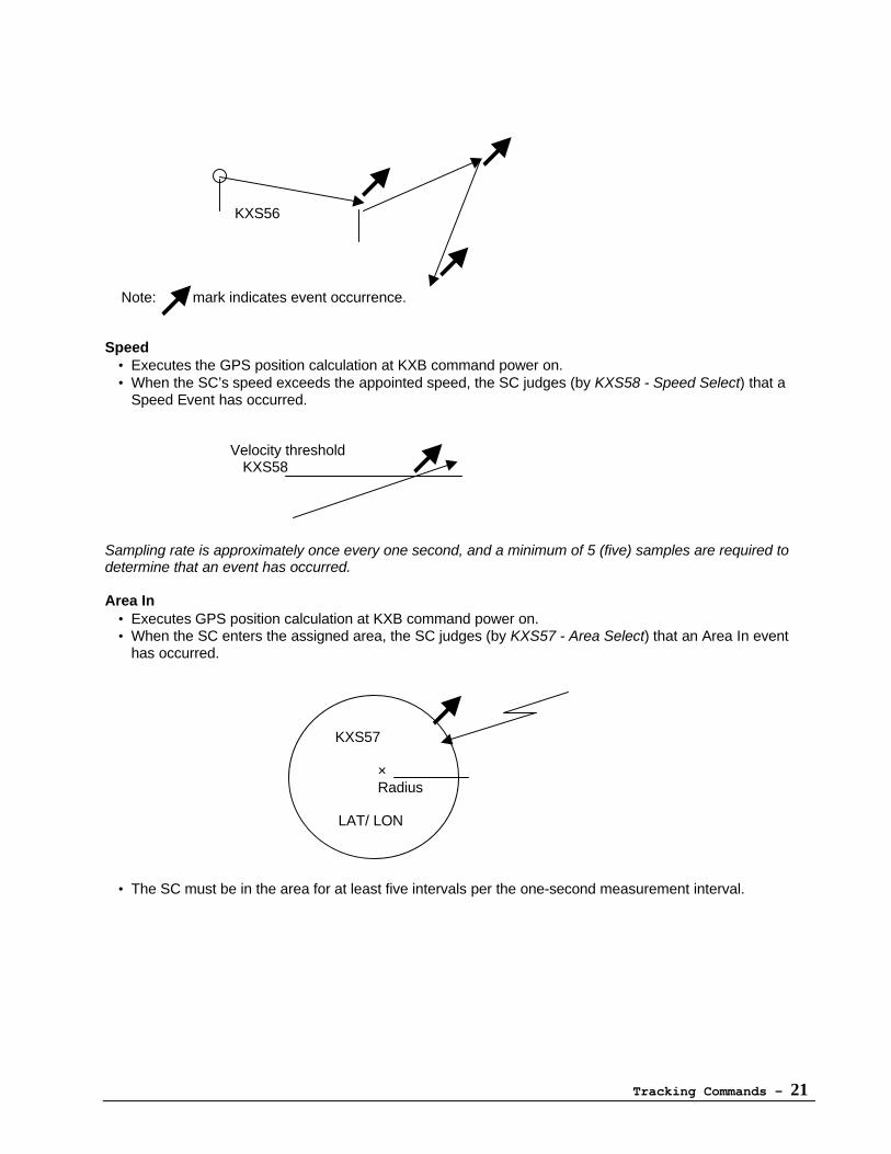
Speed• Executes the GPS position calculation at KXB command power on.• When the SC’s speed exceeds the appointed speed, the SC judges (by KXS58 - Speed Select) that a
Speed Event has occurred.
Velocity threshold KXS58
Sampling rate is approximately once every one second, and a minimum of 5 (five) samples are required todetermine that an event has occurred.
Area In• Executes GPS position calculation at KXB command power on.• When the SC enters the assigned area, the SC judges (by KXS57 - Area Select) that an Area In event
has occurred.
KXS57
×Radius
LAT/ LON
• The SC must be in the area for at least five intervals per the one-second measurement interval.
Tracking Commands - 22
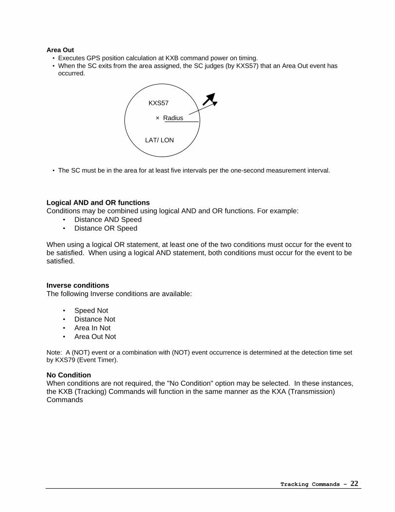
Area Out• Executes GPS position calculation at KXB command power on timing.• When the SC exits from the area assigned, the SC judges (by KXS57) that an Area Out event has
occurred.
KXS57
× Radius
LAT/ LON
• The SC must be in the area for at least five intervals per the one-second measurement interval.
Logical AND and OR functionsConditions may be combined using logical AND and OR functions. For example:
• Distance AND Speed• Distance OR Speed
When using a logical OR statement, at least one of the two conditions must occur for the event tobe satisfied. When using a logical AND statement, both conditions must occur for the event to besatisfied.
Inverse conditionsThe following Inverse conditions are available:
• Speed Not• Distance Not• Area In Not• Area Out Not
Note: A (NOT) event or a combination with (NOT) event occurrence is determined at the detection time setby KXS79 (Event Timer).
No ConditionWhen conditions are not required, the "No Condition" option may be selected. In these instances,the KXB (Tracking) Commands will function in the same manner as the KXA (Transmission)Commands
Tracking Commands - 23
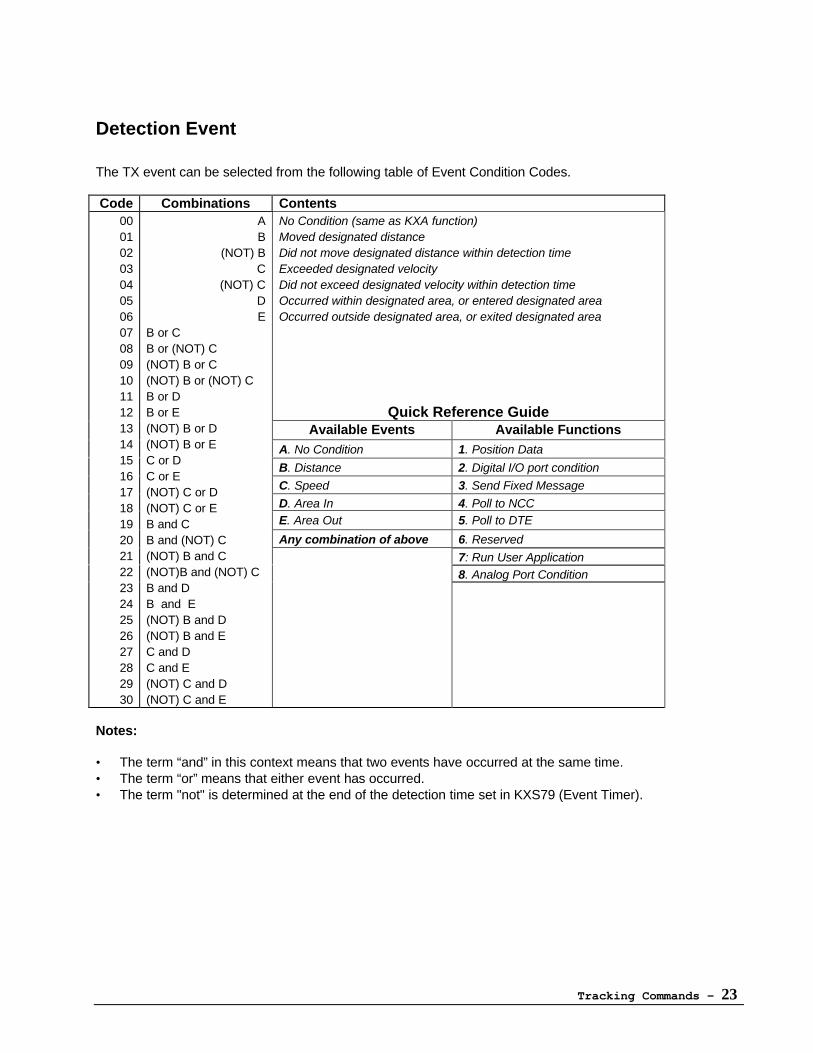
Detection Event
The TX event can be selected from the following table of Event Condition Codes.
Code Combinations ContentsNo Condition (same as KXA function)Moved designated distanceDid not move designated distance within detection timeExceeded designated velocityDid not exceed designated velocity within detection timeOccurred within designated area, or entered designated areaOccurred outside designated area, or exited designated area
Quick Reference GuideAvailable Events Available Functions
A. No Condition 1. Position Data
B. Distance 2. Digital I/O port condition
C. Speed 3. Send Fixed Message
D. Area In 4. Poll to NCCE. Area Out 5. Poll to DTE
Any combination of above 6. Reserved
7: Run User Application8. Analog Port Condition
00010203040506070809101112131415161718192021222324252627282930
AB
(NOT) BC
(NOT) CDE
B or CB or (NOT) C(NOT) B or C(NOT) B or (NOT) CB or DB or E(NOT) B or D(NOT) B or EC or DC or E(NOT) C or D(NOT) C or EB and CB and (NOT) C(NOT) B and C(NOT)B and (NOT) CB and DB and E(NOT) B and D(NOT) B and EC and DC and E(NOT) C and D(NOT) C and E
Notes:
• The term “and” in this context means that two events have occurred at the same time.• The term “or” means that either event has occurred.• The term "not" is determined at the end of the detection time set in KXS79 (Event Timer).
Tracking Commands - 24
Timing ModesThe SC has three timing modes available for the Tracking Function:
1) KXB01: Wake up at a specified time, start observation of event, perform assigned functions and transmit.§ The SC wakes up at the specified time and observes the specified event for the period set by KXS79
(Event Timer). After an additional 5 minute period has elapsed, the SC powers down.
§ Six times can be specified. Each event timer period must be more than 30 minutes apart.§ This command cannot be used in conjunction with KXA01 02, 03, 04 or with KXB02, 03.
2) KXB02: Wake up for one specified interval, start observation of event, perform assigned functions andtransmit.§ The SC wakes up for one specified interval and observes the specified event for the period set by
KXS79 (Event Timer). After an additional 5 minute period has elapsed, the SC powers down .§ When the interval is less than the detection time set in KXS79, the SC evaluates the interval as
identical with detection time (requested interval = detection time ). When interval = 0, KXB02 willcause a continuous power ON mode. That is, SC observes the event continuously and when theevent has occurred, the SC transmits the assigned messages. When detection event is specifiedwith the (NOT) mode, the SC continuously observes the event until the period set in KXS79 hasended.
§ This command cannot be set with KXA01, 02, 03, 04 or with KXB01, 03.
3) KXB03: Wake up upon satellite arrival, start observation of event, perform assigned functions andtransmit.§ The SC powers on at satellite arrival time and observes the event for the period set by KXS79. After
an additional 5 minute period has elapsed, the SC powers down .§ This command cannot be set with KXA01, 02, 03, 04 or with KXB01, 02.
Tracking Commands - 25
Notes:
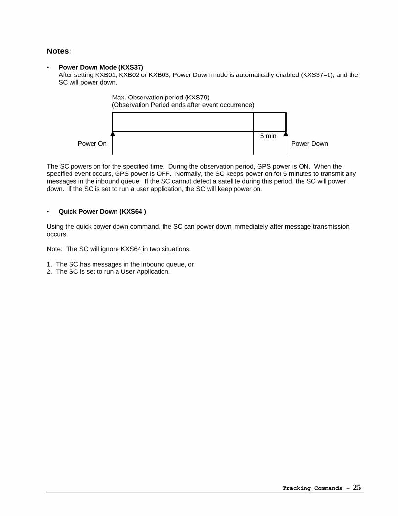
• Power Down Mode (KXS37)After setting KXB01, KXB02 or KXB03, Power Down mode is automatically enabled (KXS37=1), and theSC will power down.
Max. Observation period (KXS79) (Observation Period ends after event occurrence)
5 min Power On Power Down
The SC powers on for the specified time. During the observation period, GPS power is ON. When thespecified event occurs, GPS power is OFF. Normally, the SC keeps power on for 5 minutes to transmit anymessages in the inbound queue. If the SC cannot detect a satellite during this period, the SC will powerdown. If the SC is set to run a user application, the SC will keep power on.
• Quick Power Down (KXS64 )
Using the quick power down command, the SC can power down immediately after message transmissionoccurs.
Note: The SC will ignore KXS64 in two situations:
1. The SC has messages in the inbound queue, or2. The SC is set to run a User Application.
Tracking Commands - 26
KXB01 - Wake at Specified Time(s)
Wake up at a specified time, wait for a designated event that meets specified conditions, performassigned functions, and transmit.
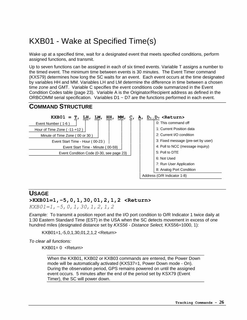
Up to seven functions can be assigned in each of six timed events. Variable T assigns a number tothe timed event. The minimum time between events is 30 minutes. The Event Timer command(KXS79) determines how long the SC waits for an event. Each event occurs at the time designatedby variables HH and MM. Variables LH and LM determine the difference in time between a chosentime zone and GMT. Variable C specifies the event conditions code summarized in the EventCondition Codes table (page 23). Variable A is the Originator/Recipient address as defined in theORBCOMM serial specification. Variables D1 ~ D7 are the functions performed in each event.
COMMAND STRUCTURE
KXB01 = T, LH, LM, HH, MM, C, A, D1.D7 <Return>Event Number ( 1-6 ) 0: This command off
Hour of Time Zone ( -11-+12 ) 1: Current Position data
Minute of Time Zone ( 00 or 30 ) 2: Current I/O condition
Event Start Time - Hour ( 00-23 ) 3: Fixed message (pre-set by user)
Event Start Time - Minute ( 00-59) 4: Poll to NCC (message inquiry)
Event Condition Code (0-30, see page 23) 5: Poll to DTE
6: Not Used
7: Run User Application
8: Analog Port Condition
Address (O/R Indicator 1-8)
USAGE>KXB01=1,-5,0,1,30,01,2,1,2 <Return>KXB01=1,-5,0,1,30,1,2,1,2
Example: To transmit a position report and the I/O port condition to O/R Indicator 1 twice daily at1:30 Eastern Standard Time (EST) in the USA when the SC detects movement in excess of onehundred miles (designated distance set by KXS56 - Distance Select, KXS56=1000, 1):
KXB01=1,-5,0,1,30,01,2,1,2 <Return>
To clear all functions:
KXB01= 0 <Return>
When the KXB01, KXB02 or KXB03 commands are entered, the Power Downmode will be automatically activated (KXS37=1, Power Down mode - On).During the observation period, GPS remains powered on until the assignedevent occurs. 5 minutes after the end of the period set by KSX79 (EventTimer), the SC will power down.
Tracking Commands - 27
KXB02 - Wake at Time Interval
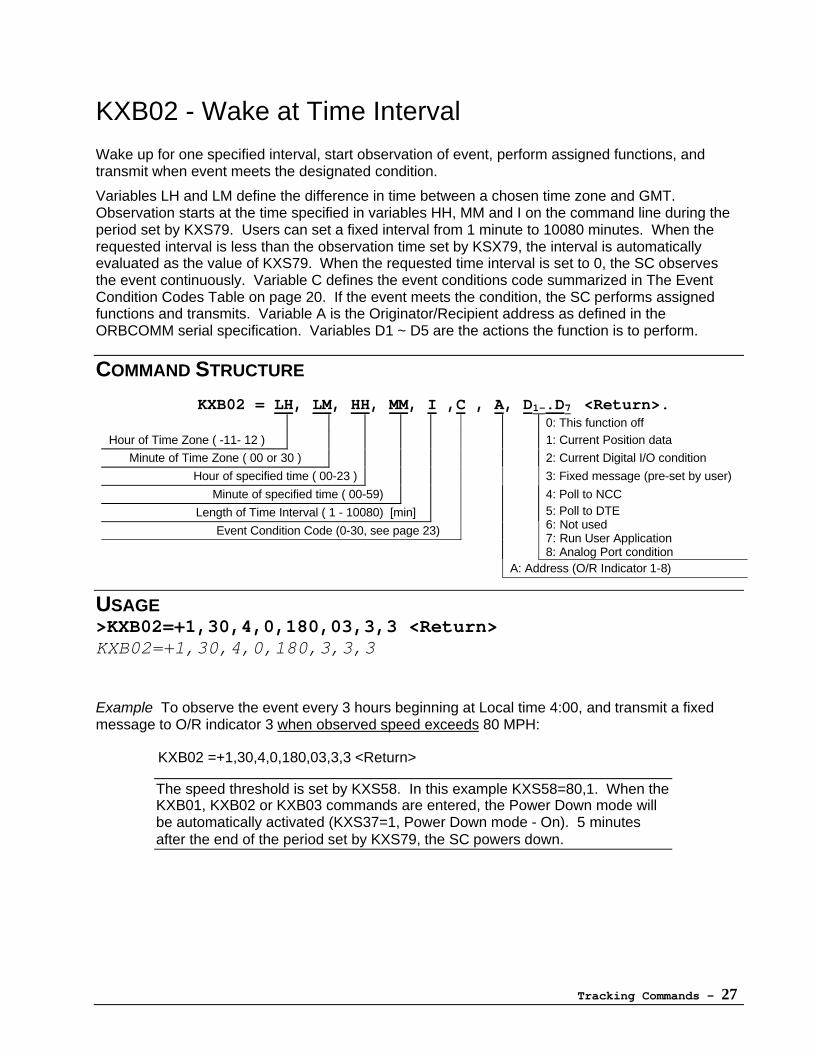
Wake up for one specified interval, start observation of event, perform assigned functions, andtransmit when event meets the designated condition.
Variables LH and LM define the difference in time between a chosen time zone and GMT.Observation starts at the time specified in variables HH, MM and I on the command line during theperiod set by KXS79. Users can set a fixed interval from 1 minute to 10080 minutes. When therequested interval is less than the observation time set by KSX79, the interval is automaticallyevaluated as the value of KXS79. When the requested time interval is set to 0, the SC observesthe event continuously. Variable C defines the event conditions code summarized in The EventCondition Codes Table on page 20. If the event meets the condition, the SC performs assignedfunctions and transmits. Variable A is the Originator/Recipient address as defined in theORBCOMM serial specification. Variables D1 ~ D5 are the actions the function is to perform.
COMMAND STRUCTURE
KXB02 = LH, LM, HH, MM, I ,C , A, D1-.D7 <Return>.0: This function off
Hour of Time Zone ( -11- 12 ) 1: Current Position data
Minute of Time Zone ( 00 or 30 ) 2: Current Digital I/O condition
Hour of specified time ( 00-23 ) 3: Fixed message (pre-set by user)
Minute of specified time ( 00-59) 4: Poll to NCC
Length of Time Interval ( 1 - 10080) [min]
Event Condition Code (0-30, see page 23)
5: Poll to DTE6: Not used7: Run User Application8: Analog Port condition
A: Address (O/R Indicator 1-8)
USAGE>KXB02=+1,30,4,0,180,03,3,3 <Return>KXB02=+1,30,4,0,180,3,3,3
Example To observe the event every 3 hours beginning at Local time 4:00, and transmit a fixedmessage to O/R indicator 3 when observed speed exceeds 80 MPH:
KXB02 =+1,30,4,0,180,03,3,3 <Return>
The speed threshold is set by KXS58. In this example KXS58=80,1. When theKXB01, KXB02 or KXB03 commands are entered, the Power Down mode willbe automatically activated (KXS37=1, Power Down mode - On). 5 minutesafter the end of the period set by KXS79, the SC powers down.
Tracking Commands - 28
KXB03 - Wake Upon Satellite Arrival
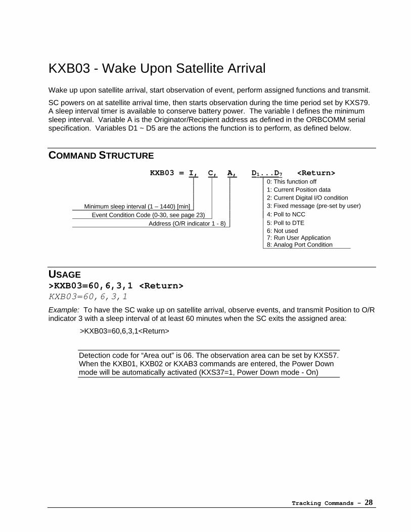
Wake up upon satellite arrival, start observation of event, perform assigned functions and transmit.
SC powers on at satellite arrival time, then starts observation during the time period set by KXS79.A sleep interval timer is available to conserve battery power. The variable I defines the minimumsleep interval. Variable A is the Originator/Recipient address as defined in the ORBCOMM serialspecification. Variables D1 ~ D5 are the actions the function is to perform, as defined below.
COMMAND STRUCTURE
KXB03 = I, C, A, D1...D7 <Return>0: This function off1: Current Position data2: Current Digital I/O condition
Minimum sleep interval (1 – 1440) [min] 3: Fixed message (pre-set by user)
Event Condition Code (0-30, see page 23) 4: Poll to NCC
Address (O/R indicator 1 - 8) 5: Poll to DTE6: Not used7: Run User Application8: Analog Port Condition
USAGE>KXB03=60,6,3,1 <Return>KXB03=60,6,3,1
Example: To have the SC wake up on satellite arrival, observe events, and transmit Position to O/Rindicator 3 with a sleep interval of at least 60 minutes when the SC exits the assigned area:
>KXB03=60,6,3,1<Return>
Detection code for “Area out” is 06. The observation area can be set by KXS57.When the KXB01, KXB02 or KXAB3 commands are entered, the Power Downmode will be automatically activated (KXS37=1, Power Down mode - On)
Tracking Commands - 29
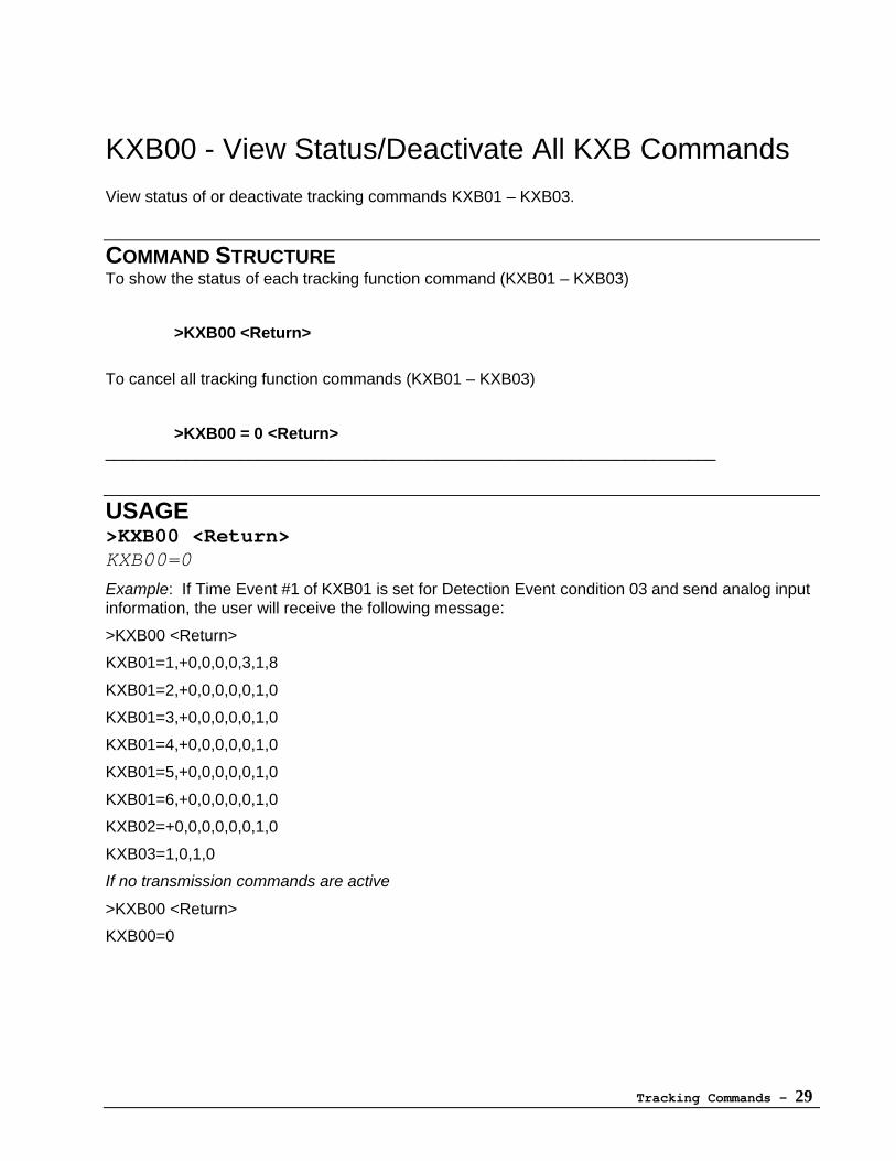
KXB00 - View Status/Deactivate All KXB Commands
View status of or deactivate tracking commands KXB01 – KXB03.
COMMAND STRUCTURETo show the status of each tracking function command (KXB01 – KXB03)
>KXB00 <Return>
To cancel all tracking function commands (KXB01 – KXB03)
>KXB00 = 0 <Return>____________________________________________________________________
USAGE>KXB00 <Return>KXB00=0
Example: If Time Event #1 of KXB01 is set for Detection Event condition 03 and send analog inputinformation, the user will receive the following message:
>KXB00 <Return>
KXB01=1,+0,0,0,0,3,1,8
KXB01=2,+0,0,0,0,0,1,0
KXB01=3,+0,0,0,0,0,1,0
KXB01=4,+0,0,0,0,0,1,0
KXB01=5,+0,0,0,0,0,1,0
KXB01=6,+0,0,0,0,0,1,0
KXB02=+0,0,0,0,0,0,1,0
KXB03=1,0,1,0
If no transmission commands are active
>KXB00 <Return>
KXB00=0

Set-Up Commands - 31
Set-Up Commands
Using the Set-Up Commands
The Set-Up Commands allow the user to precisely configure the SC for highly customizedapplications. All of the 87 commands retain their settings via internal battery, and the entirecommand set can be returned to the factory default values if desired (see "Special Commands").Further, the default values for each command are listed in this manual should it be necessary toreset individual commands.
Note that the Set-Up Command set probably contains more commands than required by anyparticular application. The interface was designed to handle every possible data communicationsapplication suitable for use within the ORBCOMM system.
To reset all Set-Up Commands to factory defaults, see Special Commands
Set-Up Commands - 32
KXS01 - Network Control Center ID
Sets the Identification Number of the Network Control Center (NCC [GCC]) that you wish themessage to pass through.
COMMAND STRUCTUREKXS01 = ID <Return>
ID: 0 - 255
Default is 1 (USA)
USAGE>KXS01=1 <Return>KXS01=1
ORBCOMM assigns the ID number for all GCCs. Other GCC IDs as ofFebruary, 2000:
Italy 120Malaysia 121Brazil 123Japan 130
Contact ORBCOMM for the latest GCC information.
Set-Up Commands - 33
KXS02 - Polling Parameter
Sets the prerequisite conditions for transmission. SC will either wait to be polled before transmittingor transmit when a satellite is acquired.
COMMAND STRUCTUREKXS02 = N <Return>
0 = Transmit the data when satellite is available.1 = Wait to be polled for data before transmitting
Default is 0
USAGE>KXS02=0 <Return>KXS02=0
Set-Up Commands - 34
KXS03 - Default Message Priority
Sets the priority level of default messages sent to the NCC.
COMMAND STRUCTUREKXS03 = N <Return>
0 Non-urgent (Lowest priority)1 Normal2 Urgent3 Special delivery (Highest priority. Used for inbound messages only.)
Default is 0
USAGE>KXS03=1 <Return>KXS03=1
Set-Up Commands - 35
KXS04 - Default Report Recipient
Sets default O/R Recipient for reports. Only O/R Indicators 1-3 are available for report addressing.
COMMAND STRUCTUREKXS04 = N <Return>
0: For Loop Back Test1-3: ORBCOMM registered speed dials, indicators 1 through 3.
Default value is 1.
USAGE>KXS04=1 <Return>KXS04=1
Refer to SC Provisioning Data Sheet for details on registered O/R Recipients.
Set-Up Commands - 36
KXS05 - Default Message/GlobalGram Recipient
Sets default recipient for messages and GlobalGrams. Up to eight indicators (speed dials) can beregistered with ORBCOMM.
COMMAND STRUCTUREKXS05 = N <Return>
0 Loop Back Test1-8 Registered user in NCC9-15 For NCC use only
Default value is 1.
USAGE>KXS05=7 <Return>KXS05=7
Refer to SC Provisioning Data Sheet for details on registered O/R Recipients.
Set-Up Commands - 37
KXS06 - Acknowledgment Level
Sets levels for message acknowledgment from the NCC/Recipient.
COMMAND STRUCTUREKXS06 = N <Return>
0. No Acknowledgment.1. Acknowledgment of non-delivery to NCC2. Acknowledgment delivery /non-delivery to NCC3. Acknowledgment of non-delivery to Recipient4. Acknowledgment of delivery/ non-delivery to Recipient
Default is 1
USAGE>KXS06=2 <Return>KXS06=2
Set-Up Commands - 38
KXS07 - Default Message Body Type
Sets the message body type for transmission.
COMMAND STRUCTUREKXS07 = T (,S) <Return>
T = Message body type.Default is 14
T = 0 or 15: Sub-message body type (S) must be usedT = 1 ~ 14: Sub-message body type (S) is not used.
Message Body Type T0= IA5TEXT (Sub Message Body Type is needed)1= Not used (formerly telex)2= Voice (under study by CCITT)3= G3 Facsimile4= G4 Class 1 Facsimile5= Teletex6= Videotext7= Nationally Defined8= Encrypted (under study by CCITT)9= Message (a message inside of a message)
10= Not used (formerly “simple formattable text”)11= Mixed Mode12= Not used13= Not used14= Bilaterally Defined (binary data)15= Externally Defined (Sub Message Body Type is needed)
S = Sub-message body typeSub Message Body Type SIf Message Body Type is 0:
2=5=
Ita2Ia5
If Message Body Type is 15:0= Text-to-Facsimile1= Text-to-Voice2= Pre-defined O/R Addresses3= Message List4= NASA 2-line format
USAGE:>KXS07=0,5 <Return>KXS07=0,5
Not all formats are supported by ORBCOMM. Contact ORBCOMM for furtherinformation.
Set-Up Commands - 39
KXS08 - Default Service Type
Sets the combination of acknowledgement level and priority for space efficiency.
COMMAND STRUCTUREKXS08 = S <Return>
S = Service TypeS: 0 - 4, 10 - 14Default is 2
Service Type S0= Normal priority with no ACK expected.1= Normal priority with only ACK of non-delivery to NCC.2= Normal priority with ACK of delivery to NCC or non-delivery to NCC.3= Normal priority with only ACK of non-delivery to recipient.4= Normal priority with ACK of delivery to recipient or non-delivery to recipient.
10= Special_delivery priority with no ACK expected.11= Special_delivery priority with only ACK of non-delivery to NCC.12= Special_delivery priority with ACK of delivery to NCC or non-delivery to NCC.13= Special_delivery priority with only ACK of non-delivery to recipient.14= Special_delivery priority with ACK of delivery to recipient or non-delivery to
recipient.
USAGE>KXS08=1 <Return>KXS08=1
Note: Numbers 5 through 9 are not defined. Do not use.

Set-Up Commands - 40
KXS09
[Reserved]
Set-Up Commands - 41
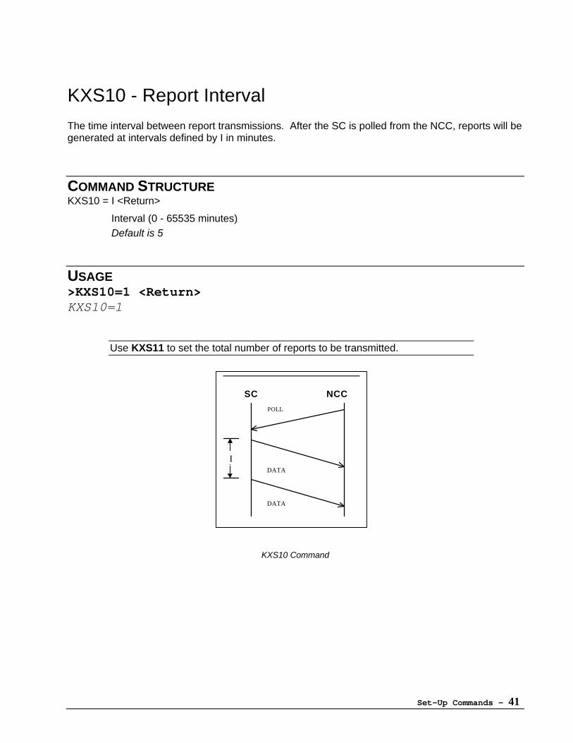
KXS10 - Report Interval
The time interval between report transmissions. After the SC is polled from the NCC, reports will begenerated at intervals defined by I in minutes.
COMMAND STRUCTUREKXS10 = I <Return>
Interval (0 - 65535 minutes)Default is 5
USAGE>KXS10=1 <Return>KXS10=1
Use KXS11 to set the total number of reports to be transmitted.
KXS10 Command
SC NCC
I
POLL
DATA
DATA
Set-Up Commands - 42
KXS11 - Number Of Reports To Be Transmitted
Number of reports to be sent from the inbound queue when the SC is polled by the NCC.If no reports are in the queue, the SC will poll the DTE.
COMMAND STRUCTUREKXS11 = N <Return>
N (0 - 255)Default is 1
USAGE>KXS11=3 <Return>KXS11=3
Use KXS10 to set the time between reports.
Set-Up Commands - 43
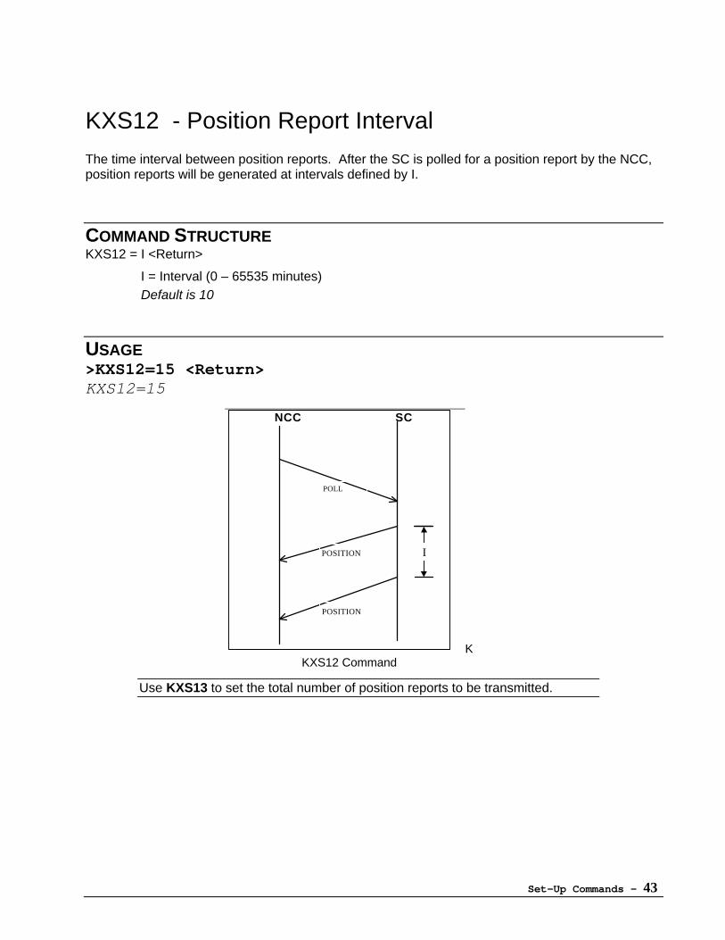
KXS12 - Position Report Interval
The time interval between position reports. After the SC is polled for a position report by the NCC,position reports will be generated at intervals defined by I.
COMMAND STRUCTUREKXS12 = I <Return>
I = Interval (0 – 65535 minutes)Default is 10
USAGE>KXS12=15 <Return>KXS12=15
Use KXS13 to set the total number of position reports to be transmitted.
NCC SC
POLL
POSITION
POSITION
I
KKXS12 Command
Set-Up Commands - 44
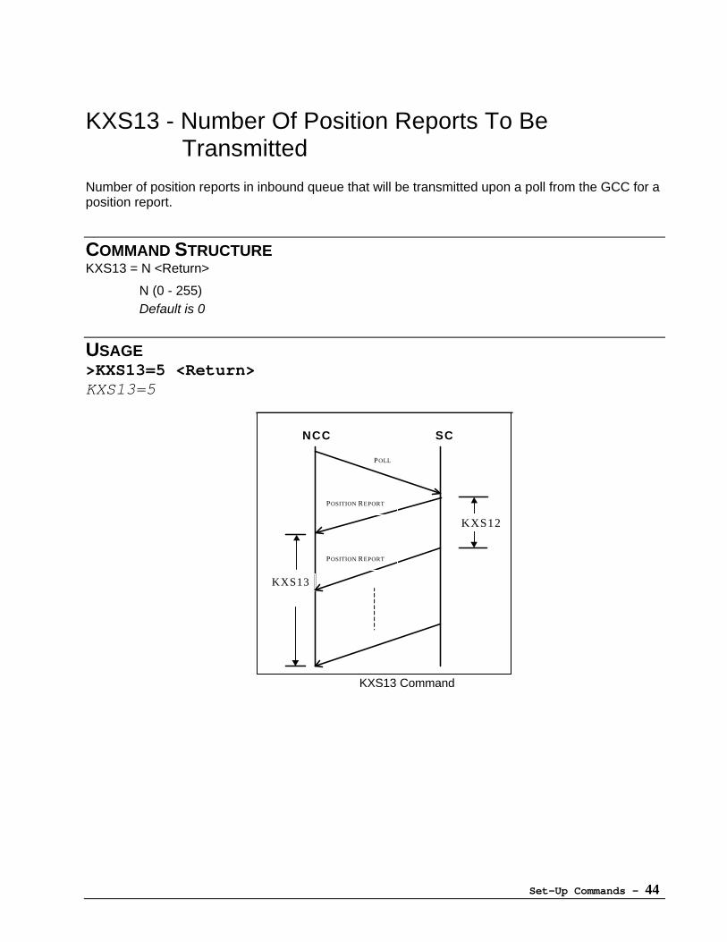
KXS13 - Number Of Position Reports To BeTransmitted
Number of position reports in inbound queue that will be transmitted upon a poll from the GCC for aposition report.
COMMAND STRUCTUREKXS13 = N <Return>
N (0 - 255)Default is 0
USAGE>KXS13=5 <Return>KXS13=5
NCC SC
KXS12
KXS13
POSITION REPORT
POSITION REPORT
POLL
KXS13 Command
Set-Up Commands - 45
KXS14 - Gateway (GWY) Search Mode
Procedure used by SC to search for Gateways.
COMMAND STRUCTUREKXS14 = S <Return>
0 Continuously search downlink band for desired1 Search band once for desired GWY. If not found, then maintain lock with first
discovered downlink.2 Maintain lock with first discovered downlink.3 Search band once for desired GWY. If not found, open search to include any
ORBCOMM GWY. If none found, maintain lock with first discovered downlink.4 Search band once for desired GWY. If not found, continuously search band for downlink having no ORBCOMM GWY or desired GWY.Default is 0.
USAGE>KXS14=2 <Return>KXS14=2
A value of 2 is recommended in GlobalGram areas. In all other areas a valueof 0 is recommended.
Set-Up Commands - 46
KXS15 - Priority Search List For Downlink
When searching for a link, up to 24 channels can be given priority over the remaining channelsby being included in the Priority Search List.
COMMAND STRUCTUREKXS15 = S0, C0 <Return>KXS15 = S1, C1 <Return>KXS15 = S2, C2 <Return>
.
.
.KXS15 = S23, C23 <Return>S = Priority Search list ( 0 - 23 )C = Available Channels ( 1 - 399 )
Default is 80,90,100,174,184,265,275,285,295,320,115,125,159,271,283
USAGE>KXS15=0,230 <Return>KXS15=0,230>KXS15=1,396 <Return>KXS15=1,396>KXS15=2,307 <Return>KXS15=2,307>KXS15=3,283 <Return>KXS15=3,283
If the search of this list is unsuccessful, the remaining channels will besearched.
The channel list will be revised automatically when the SC receives a downlinkchannel from the satellite.
Downlink Channel information is received a minimum of every 16 seconds.
Set-Up Commands - 47
KXS16 - Packet Error Acceptance Level
Sets the maximum number of packet errors encountered before selecting next channel.
COMMAND STRUCTUREKXS16 = T <Return>
T = Threshold (1- 100)Default is 60
USAGE>KXS16=47 <Return>KXS16=47
KXS16 must be set in the range of 0 - 50 when KXS17 (Checksum FrameCount) is set to 1.
Set-Up Commands - 48
KXS17 - Checksum Frame Count
Sets the number of frames to be measured for an error rate on data received from a satellite.
COMMAND STRUCTUREKXS17 = C <Return>
C = Count (1 - 16)Default is 2
USAGE>KXS17=4 <Return>KXS17=4
If KXS16 (Packet Error Acceptance Level) is set in the range of 51 - 100, thenKXS17 (Checksum Frame Count) must be set to a value greater than 1.
Set-Up Commands - 49
KXS18 - Continuous Position Determination
Set the SC to Continuous Position Determination mode. This command affects both Doppler andGPS calculations.
If the Continuous Position Determination is set to ON, GPS position calculation is refreshedapproximately every 1 second and position reports are sent every 2 minutes.
COMMAND STRUCTUREKXS18 = N <Return>
0: Continuous Positioning Off1: Continuous Positioning OnDefault is 0
USAGE>KXS18=1 <Return>KXS18=1
KXS18 cannot be set to 1 when KXS24 is set to 0.
When KXA/KXB command is activated, KXS18 will be reset to 0.
Due to the high rate of report generation when this command is active, it isrecommended that this function ONLY BE USED FOR TEST PURPOSESWITH DTE.
Set-Up Commands - 50
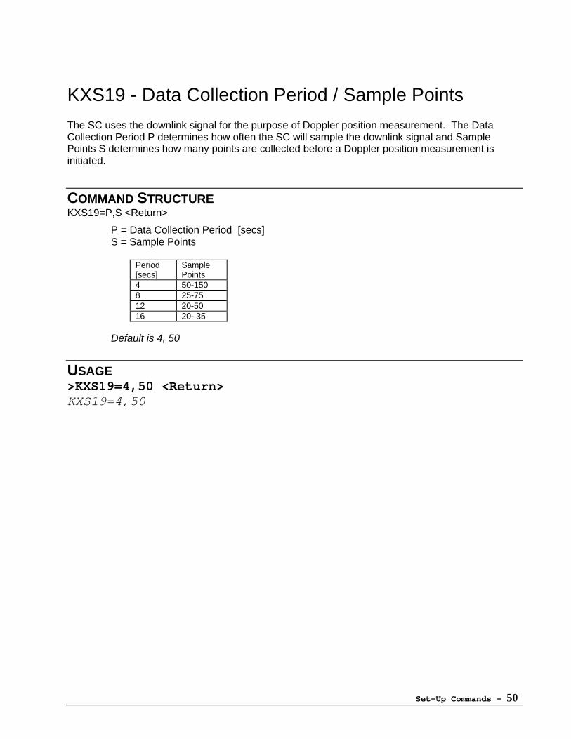
KXS19 - Data Collection Period / Sample Points
The SC uses the downlink signal for the purpose of Doppler position measurement. The DataCollection Period P determines how often the SC will sample the downlink signal and SamplePoints S determines how many points are collected before a Doppler position measurement isinitiated.
COMMAND STRUCTUREKXS19=P,S <Return>
P = Data Collection Period [secs]S = Sample Points
Period[secs]
SamplePoints
4 50-1508 25-7512 20-5016 20- 35
Default is 4, 50
USAGE>KXS19=4,50 <Return>KXS19=4,50
Set-Up Commands - 51
KXS20 - Position Data Age Limit
Sets a maximum age in minutes for the previously measured position to be transmitted.
When the SC is polled for a position report it will compare the age of the last position fix with thePosition Data Age Limit (KXS20). If the age of the last position fix (KXS23) is less than the value ofthe Age Limit, the SC sends two position reports. The first report contains the values of Latitudeand Longitude in KXS23. The second report contains the values just calculated.
If age of the last position fix is greater than the value of the Age Limit, the SC sends only theposition report containing the values just calculated. When the SC is polled for Position reports withages greater than the Age Limit they are not transmitted.
COMMAND STRUCTUREKXS20 = A <Return>
A = Age (0 - 65535) [min]Default is 360
USAGE>KXS20=37700 <Return>KXS20=37700
Set-Up Commands - 52
KXS21 - Minimum Quality Indicator for DopplerPositioning
Sets a minimum threshold for Doppler measurement accuracy. Doppler position calculations arecontinuous despite the setting of the Quality Indicator, however if the accuracy threshold is NOTachieved no Doppler report is issued.
When the quality threshold is not achieved and the SC receives a poll from the NCC the SC willrespond with an acknowledgement instead of a position report. When the quality threshold is notachieved and the SC receives a poll from the DTE the SC will continue measuring position until thethreshold is achieved.
COMMAND STRUCTUREKXS21 = I <Return>
Q = Quality Indicator (0 - 15)0 = Doppler reporting function is off.1 = Greater accuracy / decreased probability of a report15 = Less accuracy / increased probability of a reportDefault is 3
USAGE>KXS21=3 <Return>KXS21=3
3 is the optimum setting. KXS21 has no effect upon GPS position reports.
Set-Up Commands - 53
KXS22 - Maximum Age of Orbital Elements
Sets the maximum acceptable age of orbital elements used in calculation of satellite rise time.
COMMAND STRUCTUREKXS22 = A <Return>
A: Age (12 - 8760) [hours]Default is 672
USAGE>KXS22=24 <Return>KXS22=24
If age of orbital elements is greater than value of KXS22, the SC enters thesatellite search mode to retrieve new orbital elements. Orbital elements areupdated each time a satellite is acquired.
For more information covering the satellite search mode see KXS38 (MinimumPower Down Interval), KXS39 (Inactive Interval) and Appendix F: Power On-Off.
Set-Up Commands - 54
KXS23 - Set Latitude / Longitude
Sets the current position.
COMMAND STRUCTUREKXS23 = XXX.XXXX, YYYY.YYYY <Return>
XXX.XXXX :Latitude (-90.0000 - +90.0000)YYYY.YYYY :Longitude (-180.0000 - +180.0000)Default is +0.0000,+0.0000
USAGE>KXS23=+35.5410, -79.5220 <Return>KXS23=+35.5410, -79.5220
KXS23 can either be set manually or automatically. The SC will update KXS23whenever it measures its current position by either GPS or Dopplermeasurement.
Valid position data must be present in KXS23 for the SC to calculate satelliterise time. The results of satellite rise time calculations are used to determineSC's next wake-up time.
Set-Up Commands - 55
KXS24 - Internal Position Calculation
Enables/disables Internal Position Calculation. This command affects both Doppler and GPScalculations.
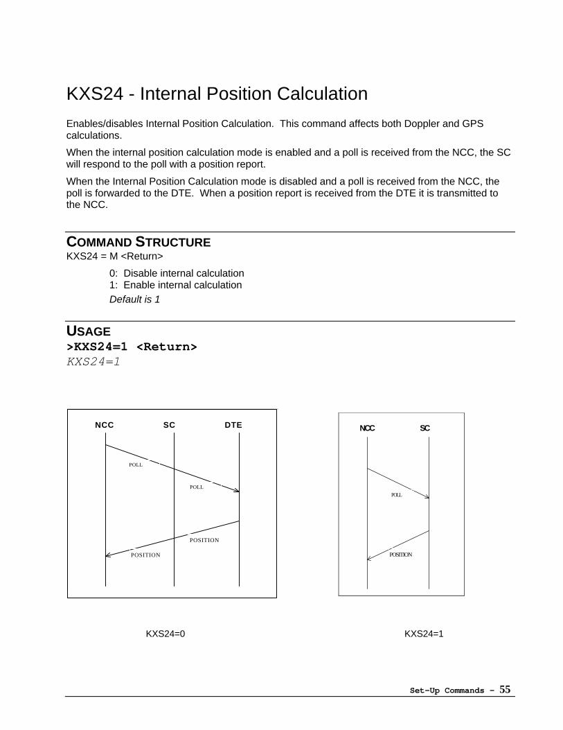
When the internal position calculation mode is enabled and a poll is received from the NCC, the SCwill respond to the poll with a position report.
When the Internal Position Calculation mode is disabled and a poll is received from the NCC, thepoll is forwarded to the DTE. When a position report is received from the DTE it is transmitted tothe NCC.
COMMAND STRUCTUREKXS24 = M <Return>
0: Disable internal calculation1: Enable internal calculationDefault is 1
USAGE>KXS24=1 <Return>KXS24=1
NCC SC DTE
POLL
POSITION
POLL
POSITION
NCC SC
POLL
POSITION
KXS24=0 KXS24=1
Set-Up Commands - 56
KXS25 - GPS Data Format
Defines the format of the GPS data sent to the NCC.
COMMAND STRUCTUREKXS25 = F <Return>
F = Format0 LAT/ LON sentence mode1 NMEA 0183 sentence modeDefault is 0
USAGE>KXS25=1 <Return>KXS25=1
The data format will be determined by the combination of settings for KXS25and KXS60.
See Appendix D for more detail.
Set-Up Commands - 57
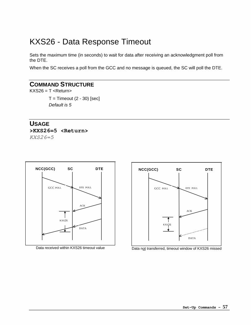
KXS26 - Data Response Timeout
Sets the maximum time (in seconds) to wait for data after receiving an acknowledgment poll fromthe DTE.
When the SC receives a poll from the GCC and no message is queued, the SC will poll the DTE.
COMMAND STRUCTUREKXS26 = T <Return>
T = Timeout (2 - 30) [sec]Default is 5
USAGE>KXS26=5 <Return>KXS26=5
NCC(GCC) SC DTE
GCC POLL
DATA
DTE POLL
ACK
KXS26
Data not transferred, timeout window of KXS26 missed
NCC(GCC) SC DTE
GCC POLL
DATA
DTE POLL
ACK
KXS26
Data received within KXS26 timeout value

Set-Up Commands - 58
KXS27 - Serial Packet Acknowledgment Timeout
Sets the time interval that the SC will wait for an acknowledgment after sending packet data to theDTE. If no acknowledgement is received, the SC will continue to re-send data until the number oftransmissions equals the value set by KXS28.
COMMAND STRUCTUREKXS27 = T <Return>
T: Timeout (1 - 30) [sec]Default is 5
USAGE>KXS27=5 <Return>KXS27=5
SC DTE
KXS27
DATA
ACK
KXS27 Command
Set-Up Commands - 59
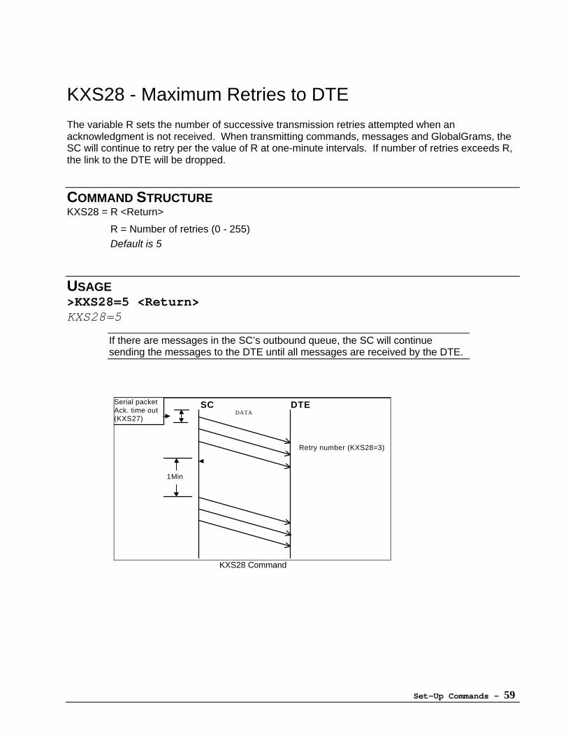
KXS28 - Maximum Retries to DTE
The variable R sets the number of successive transmission retries attempted when anacknowledgment is not received. When transmitting commands, messages and GlobalGrams, theSC will continue to retry per the value of R at one-minute intervals. If number of retries exceeds R,the link to the DTE will be dropped.
COMMAND STRUCTUREKXS28 = R <Return>
R = Number of retries (0 - 255)Default is 5
USAGE>KXS28=5 <Return>KXS28=5
If there are messages in the SC’s outbound queue, the SC will continuesending the messages to the DTE until all messages are received by the DTE.
SC DTE
1Min
DATA
Serial packetAck. time out(KXS27)
Retry number (KXS28=3)
KXS28 Command
Set-Up Commands - 60
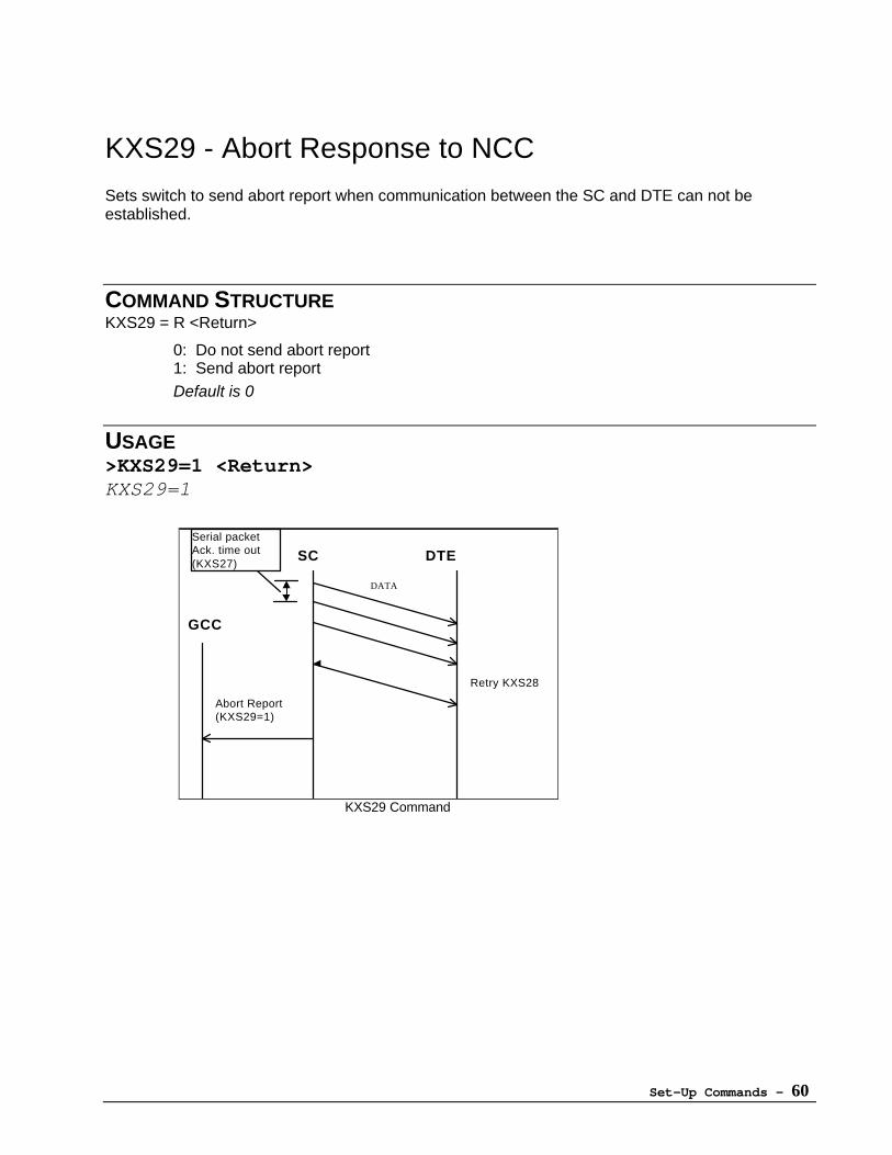
KXS29 - Abort Response to NCC
Sets switch to send abort report when communication between the SC and DTE can not beestablished.
COMMAND STRUCTUREKXS29 = R <Return>
0: Do not send abort report1: Send abort reportDefault is 0
USAGE>KXS29=1 <Return>KXS29=1
SC DTE
GCC
Abort Report(KXS29=1)
DATA
Serial packetAck. time out (KXS27)
Retry KXS28
KXS29 Command
Set-Up Commands - 61
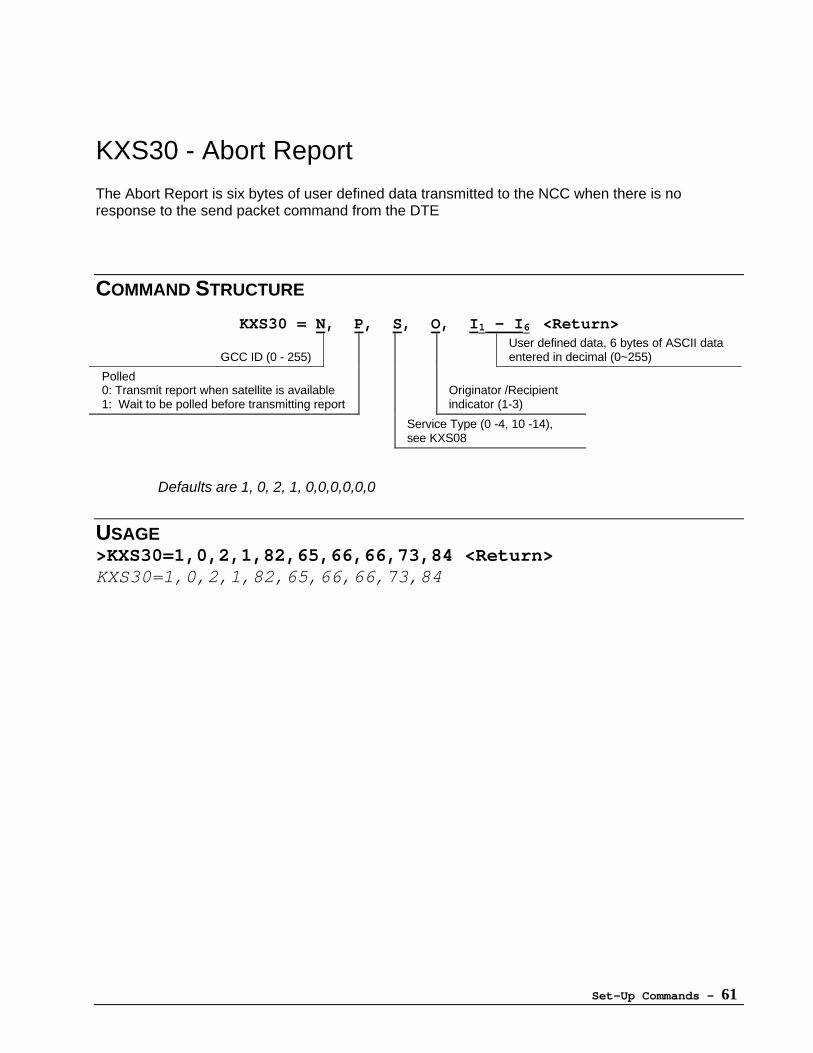
KXS30 - Abort Report
The Abort Report is six bytes of user defined data transmitted to the NCC when there is noresponse to the send packet command from the DTE
COMMAND STRUCTURE
KXS30 = N, P, S, O, I1 - I6 <Return>
GCC ID (0 - 255)User defined data, 6 bytes of ASCII dataentered in decimal (0~255)
Polled0: Transmit report when satellite is available1: Wait to be polled before transmitting report
Originator /Recipientindicator (1-3)
Service Type (0 -4, 10 -14),see KXS08
Defaults are 1, 0, 2, 1, 0,0,0,0,0,0
USAGE>KXS30=1,0,2,1,82,65,66,66,73,84 <Return>KXS30=1,0,2,1,82,65,66,66,73,84
Set-Up Commands - 62
KXS31 - Operation Mode
Selects the Communication mode between the SC and DTE.
COMMAND STRUCTUREKXS31 = M <Return>
0: Protocol mode1: Byte modeDefault is 0
USAGE>KXS31=1 <Return>KXS31=1
When KXA04 (Byte Mode) is activated, KXS31 will be set to 1 (Byte mode).
If KXS31 is set to 1 (Byte Mode), set KXS32 (Byte Mode Trigger), KXS33(Byte Mode Timeout) and KXS34 (Byte Mode Length), KXS35 (Byte Mode TXSOM/EOM, RX SOM/EOM), KXS36 (Byte Mode Message Type).
If KXS31 is set to 0 (Protocol mode), set KXS43 to (len = 8).
If KXS43 (len) equals 7, KXS31 must not be set to 0.
For further information on Byte Mode operation, see Appendix B: Byte ModeOperations.
Set-Up Commands - 63
KXS32 - Byte Mode Trigger
Sets the trigger type for transmission when byte mode communication has been selected.
COMMAND STRUCTUREKXS32 = T <Return>
T= Trigger0: Transmit upon meeting the conditions of Byte Mode Length (KXS34) or Byte Mode Timeout (KXS33)1: Transmit after detection of byte mode, receive start of message (SOM) and end of message (EOM) characters (KXS35).
Default is 0
USAGE>KXS32=0 <Return>KXS32=0
After the KXS32 is set, configure KXS31 (Operation Mode), KXS33 (ByteMode Timeout), KXS34 (Byte Mode Length) and KXS36 (Byte Mode MessageType).
SOM and EOM characters are defined by KXS35.
Byte mode commands KXS31, 32, 33, and 34 can be automated by usingKXA04.
See Appendix B: Byte Mode Operations.
Set-Up Commands - 64
KXS33 - Byte Mode Timeout
Sets the time interval the SC waits after receiving first byte before framing the bytes as an inboundreport, message, or GlobalGram.
COMMAND STRUCTUREKXS33 = T <Return>
T: Timeout (1-3600) [sec]Default is 1 sec
USAGE>KXS33=5 <Return>KXS33=5
Byte mode commands KXS31, 32, 33, and 34 can be automated by usingKXA04.
See Appendix B: Byte Mode Operations.
Set-Up Commands - 65
KXS34 - Byte Mode Length
Sets the number of bytes in an inbound report, message, or GlobalGram
COMMAND STRUCTUREKXS34 = L <Return>
L: Length (1 to maximum inbound queue size per KXS48)Default is 6
USAGE>KXS34=50 <Return>KXS34=50
Byte Mode Length must be transmitted within the time specified by KXS33(Byte Mode Timeout).
KXS48 determines maximum buffer size.
Byte mode commands KXS31, 32, 33, and 34 can be automated by usingKXA04.
See Appendix B: Byte Mode Operations.
Set-Up Commands - 66
KXS35 - Byte Mode TX SOM/EOM / RX SOM/EOMDefines the start-of-message and end-of-message ASCII characters used for communication between the SCand DTE.
TX SOM: Start of message character for communication from the SC to the DTE.
TX EOM: End of message character for communication from the SC to the DTE.
RX SOM: Start of message character for communication from the DTE to the SC
RX EOM: End of message character for communication from the DTE to the SC
COMMAND STRUCTUREKXS35 = A, B, C, D <Return>
A: TX_SOMB: TX_EOM ( 0 - 127 )C: RX_SOMD: RX_EOMDefault is 2, 3, 2, 3
USAGE>KXS35=2,3,2,3 <Return>KXS35=2,3,2,3
SOM and EOM are entered in decimal form. SOM and EOM cannot have thesame value.
Byte mode commands KXS31, 32, 33 and 34 can be automated by usingKXA04.
See Appendix B: Byte Mode Operations and Appendix C: ASCII Tables
Set-Up Commands - 67
KXS36 - Byte Mode Message Type
Sets the type of data sent by the SC when in Byte mode.
COMMAND STRUCTUREKXS36 = T <Return>
0: Inbound Message1: Report (6 bytes)2: GlobalGramDefault is 1
USAGE>KXS36=0 <Return>KXS36=0
Byte mode commands KXS31, 32, 33 and 34 can be automated by usingKXA04.
See Appendix B: Byte Mode Operations.
Set-Up Commands - 68
KXS37 - Power Down Mode
When the Power Down Mode is activated the SC will sleep until the calculated wake up time.
COMMAND STRUCTUREKXS37 = M <Return>
0: Continuous Power ON1: Power Down Mode ActiveDefault is 1
USAGE>KXS37=0 <Return>KXS37=0
Wake up times are defined by KXA/KXB commands.
If KXA01, KXA02 or KXA03 is enabled, KXS37 is set to 1.If KXA04 or KXA05 is enabled, KXS37 is set to 0.
If KXB01, KXB02 or KXB03 is enabled, KXS37 is set to 1 .
If continuous power on is desired, KXS37 must be reset to 0 following thesetting of KXA/KXB commands.
See Appendix F: Power On - Off for more detail on power cycling.
Set-Up Commands - 69
KXS38 - Minimum Power Down Interval
Sets the minimum number of minutes the SC remains powered down.
COMMAND STRUCTUREKXS38 = I <Return>
I: Interval (0 - 535,600) [min]Default is 0
USAGE>KXS38=60 <Return>KXS38=60
If KXAKXB commands are used, KXS38 setting has no effect upon SCoperation.
KXS38=0 will cause the SC power to cycle as follows: ON time will be fiveminutes, OFF time is determined by KXS39 (Inactive Interval).
For the SC to sleep, several conditions must be met:
1. Power Down mode (KXS37) must be activated
2. The SC must have both position fix (KXS23) and satellite orbital elements(KXS22)
Set-Up Commands - 70
KXS39 - Inactive Interval
Sets the length of time (in seconds) that the SC will power down when satellite arrival is not known,and all channels per KXS15 (Priority Search List for Downlink) have been searched unsuccessfully.
COMMAND STRUCTUREKXS39 = I <Return>
I: (0 - 86,400) [sec]Default is 0
USAGE>KXS39=300 <Return>KXS39=300
See Appendix F: Power On- Off for more detail.
Set-Up Commands - 71
KXS40 - Power Save Mode
Using the Power Save Mode forces the VHF RF receiver section to power down when inactive.
COMMAND STRUCTUREKXS40 = M <Return>
M = 0 OFFM = 1 ONDefault is 0
USAGE>KXS40=0 <Return>KXS40=0
Use with CAUTION, as indiscriminate usage will affect communication quality.Default setting recommended for optimum performance.
Set-Up Commands - 72
KXS41 - Inbound Flow ControlSets flow control for inbound communication (DTE to SC).
COMMAND STRUCTUREKXS41 = C <Return>
0: Controlled by CTS1: No inbound flow controlDefault is 1
USAGE>KXS41=1 <Return>KXS41=1
KXS41 must be set to 0 when KXS44 (Duplex Switch) is set to 0 (Half Duplex)
Set-Up Commands - 73
KXS42 - Outbound Flow Control
Sets flow control for outbound data communication (SC to DTE).
COMMAND STRUCTUREKXS42 = C <Return>
0: Controlled by RTS1: No outbound flow controlDefault is 1
USAGE>KXS42=1 <Return>KXS42=1
KXS42 cannot be set to 1 when KXS44 (Duplex Switch) is set to 0 (Half Duplex)
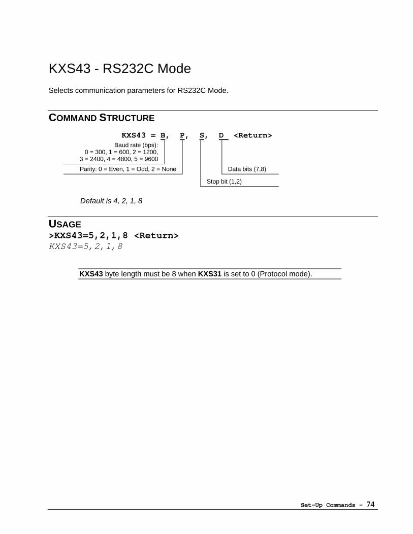
Set-Up Commands - 74
KXS43 - RS232C Mode
Selects communication parameters for RS232C Mode.
COMMAND STRUCTURE
KXS43 = B, P, S, D <Return>Baud rate (bps):
0 = 300, 1 = 600, 2 = 1200,3 = 2400, 4 = 4800, 5 = 9600
Parity: 0 = Even, 1 = Odd, 2 = None Data bits (7,8)
Stop bit (1,2)
Default is 4, 2, 1, 8
USAGE>KXS43=5,2,1,8 <Return>KXS43=5,2,1,8
KXS43 byte length must be 8 when KXS31 is set to 0 (Protocol mode).
Set-Up Commands - 75
KXS44 - Duplex Switch
Selects duplex mode for communication between SC and DTE.
COMMAND STRUCTUREKXS44 = D <Return>
D: Duplex (0 - 2)0: Half Duplex1: Full Duplex2: Receive onlyDefault is 1
USAGE>KXS44=1 <Return>KXS44=1
KXS41 (Inbound Flow Control) and KXS42 (Outbound Flow Control) must be set to 0when KXS44 is set to 0.
Set-Up Commands - 76
KXS45 - Inbound Message Treatment
The Inbound Message Treatment switch determines how new messages will be managed when theinbound message queue is full. The value of T will determine if new messages are ignored orallowed to overwrite the oldest message in the queue.
COMMAND STRUCTUREKXS45 = T <Return>
0: Ignore new messages and send NACK to DTE1: Overwrite old messages with new messagesDefault is 0
USAGE>KXS45=1 <Return>KXS45=1
When KXS45 = 1 and the buffer is full, the oldest message will be discarded tomake room for the new message.
Set-Up Commands - 77
KXS46 - Outbound Message Treatment
The Outbound Message Treatment switch determines how new messages will be managed whenthe outbound message queue is full. The value of T will determine if new messages are ignored orallowed to overwrite the oldest message in the queue.
COMMAND STRUCTUREKXS46 = T <Return>
0: Ignore new messages1: Overwrite old messages with new messagesDefault is 0
USAGE>KXS46=1 <Return>KXS46=1
When KXS46 = 1 and the buffer is full, the oldest message will be discarded tomake room for the new message.
Set-Up Commands - 78
KXS47 - Save Inbound Message
Detects the outcome of the transmission routine and either re-queues or deletes inbound messagesdependent upon the variable S.
COMMAND STRUCTUREKXS47 = S <Return>
0: Message erased regardless of the outcome of the transmission routine.1: Message re-queued and re-transmitted until the transmission routine is completed.Default is 1
USAGE>KXS47=1 <Return>KXS47=1
Used in conjunction with KXS45 to manage the inbound queue.
Set-Up Commands - 79
KXS48 - Inbound / Outbound Queue Size
Determines how the 8KByte queue area is divided.
COMMAND STRUCTUREKXS48 = S <Return>
1: 1K/7K (1KB inbound / 7KB outbound)2: 2K/6K3: 3K/5K4: 4K/4K5: 5K/3K6: 6K/2K7: 7K/1KDefault is 4
USAGE>KXS48=3 <Return>KXS48=3
This command is available only from the DTE.
The inbound queue size must be greater than KXS34 (Byte Mode Length)
Set-Up Commands - 80
KXS49 - UTC Time Adjust
UTC Time Adjust compensates for communication propagation and circuit processing delays in theSC.
COMMAND STRUCTUREKXS49 = A <Return>
Adjust (0 - 20) [sec]Default is 0
USAGE>KXS49=0 <Return>KXS49=0
KXS49 is set at the factory and should not be adjusted.
Set-Up Commands - 81
KXS50 - PIN Code
Select a security PIN code between the values of 0 and 9999.
COMMAND STRUCTUREKXS50 = C <Return>
C: (0 – 9999)Default is 0
USAGE>KXS50=0909 <Return>KXS50=909
User can set PIN code when provisioning the SC.
Set-Up Commands - 82
KXS51 - Automatic GlobalGram Polling
Sets the switch to automatically poll the satellite to receive GlobalGram messages. This commandfunctions only when the satellite is in GlobalGram mode.
COMMAND STRUCTUREKXS51 = S <Return>
S= 0 OFF (No automatic polling)S= 1 ON (Send polling command)Default is 0
USAGE>KXS51=1 <Return>KXS51=1
When the satellite is in GlobalGram mode and the Automatic GlobalGramPolling is set, the SC will automatically poll the satellite for GlobalGrammessages.
This command has no effect upon the SC’s transmission of GlobalGrams.
Set-Up Commands - 83
KXS52 - GPS Datum Select
101 mapping standards (DATUM) are selectable using the GPS Datum Select command.
Use Appendix H to choose a mapping standard for the region where the SC will be located. Forworldwide usage, the default value of WGS84 is recommended.
COMMAND STRUCTUREKXS52 = D <Return>
Datum: 0 - 100Default is 0 (WGS84)
USAGE>KXS52=1 <Return>KXS52=1
This datum has no effect upon Doppler calculations.
Changing of datum clears previous position data in GPS resulting incold start for next position fix.
Set-Up Commands - 84
KXS53 - RTS Logic Setting
Sets the RTS logic level.
COMMAND STRUCTUREKXS53 = S <Return>
0: ORBCOMM Spec “H”= True “L”= False1: Normal Spec “H”= False “L”= TrueDefault is 0
USAGE>KXS53=1 <Return>KXS53 = 1
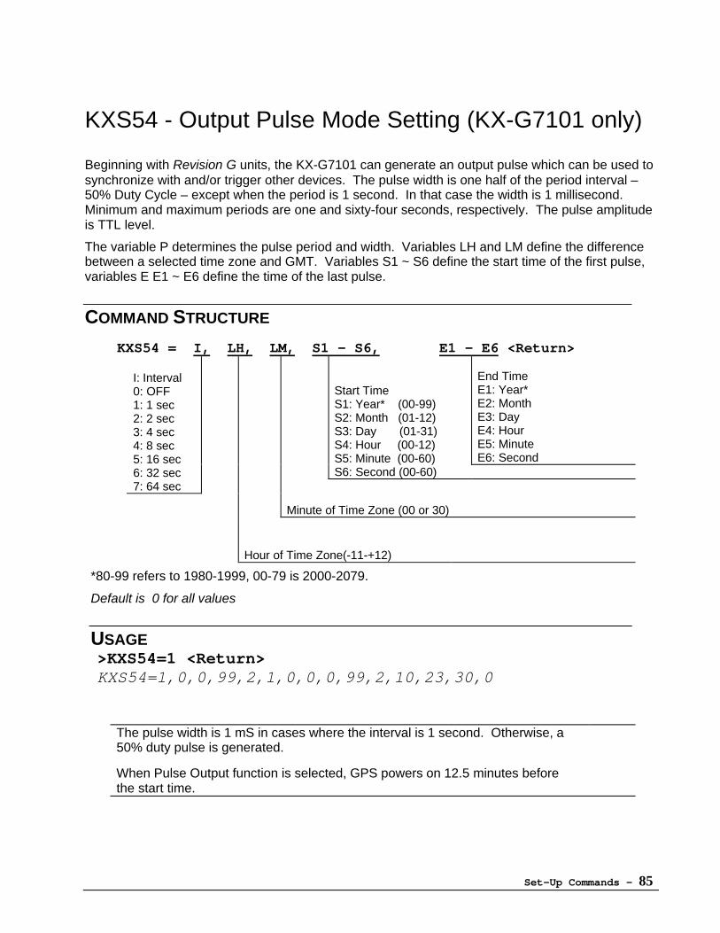
Set-Up Commands - 85
KXS54 - Output Pulse Mode Setting (KX-G7101 only)
Beginning with Revision G units, the KX-G7101 can generate an output pulse which can be used tosynchronize with and/or trigger other devices. The pulse width is one half of the period interval –50% Duty Cycle – except when the period is 1 second. In that case the width is 1 millisecond.Minimum and maximum periods are one and sixty-four seconds, respectively. The pulse amplitudeis TTL level.
The variable P determines the pulse period and width. Variables LH and LM define the differencebetween a selected time zone and GMT. Variables S1 ~ S6 define the start time of the first pulse,variables E E1 ~ E6 define the time of the last pulse.
COMMAND STRUCTURE
KXS54 = I, LH, LM, S1 - S6, E1 - E6 <Return>
End TimeE1: Year*E2: MonthE3: DayE4: HourE5: MinuteE6: Second
Start TimeS1: Year* (00-99)S2: Month (01-12)S3: Day (01-31)S4: Hour (00-12)S5: Minute (00-60)S6: Second (00-60)
I: Interval0: OFF1: 1 sec2: 2 sec3: 4 sec4: 8 sec5: 16 sec6: 32 sec7: 64 sec
Minute of Time Zone (00 or 30)
Hour of Time Zone(-11-+12)
*80-99 refers to 1980-1999, 00-79 is 2000-2079.
Default is 0 for all values
USAGE>KXS54=1 <Return>KXS54=1,0,0,99,2,1,0,0,0,99,2,10,23,30,0
The pulse width is 1 mS in cases where the interval is 1 second. Otherwise, a50% duty pulse is generated.
When Pulse Output function is selected, GPS powers on 12.5 minutes beforethe start time.
Set-Up Commands - 86
KXS55 - Analog Port Select
Analog port values can be transmitted using the KXB commands (all SC revision levels), and KXAcommands (revision F and higher). Analog Port Select determines which analog port values aretransmitted.
COMMAND STRUCTUREKXS55 = P [P, ...] <Return>
P: Number of analog port (1 - 7)Default is 1,2
USAGE>KXS55=2,3,4 <Return>KXS55=2,3,4
Analog ports 1 and 2 are the standard ports.
Ports 3-7 are currently reserved for future use.
Set-Up Commands - 87
KXS56 - Distance Select
Distance can be used as one of several event triggers for the Tracking commands. The DistanceSelect command allows selection of units and length of distance to be used as a trigger. Length isresolvable from 0.1 to 5000 units in 0.1 unit increments.
COMMAND STRUCTUREKXS56 = L,U <Return>
L: Length (0.1 - 5000)U: Unit
0: Km1: Mile2: NM (Nautical Mile)
Default is 1.0, 0
USAGE>KXS56=3.6,1 <Return>KXS56=3.6,1
Set-Up Commands - 88
KXS57 - Area Select
Departure from a specified area can be used as one of several event triggers for the Trackingcommands. The Area Select command defines the specific area as a circle with a center point,radius and distance unit.
The center point is specified using latitude and longitude coordinates with the variables LAT andLON respectively. Each of these coordinates can be specified to the 10-3 degree.
The radius is defined using the variables R and U. R is the length of the radius where the length ismeasured in units determined by the variable U. Radius length can be between 0.1 and 5000 unitsin 0.1-unit increments.
COMMAND STRUCTUREKXS57 = LAT, LON, R, U <Return>
LAT: Center position of circle (latitude) (-90.0000 - +90.0000)LON: Center position of circle (longitude) (-180.0000 - +180.0000)R: Radius (0.1 - 5000)U: Unit
0: Km1: Mile2: NM (Nautical Mile)
Default is 0.0, 0.0, 1, 0
USAGE>KXS57 +40.7889, -74.0732, 10, 1 <Return>KXS57=+40.7889, -74.0732, 10.0, 1
Set-Up Commands - 89
KXS58 - Speed Select
The speed of the SC can be used as one of several event triggers for the Tracking commands. TheSpeed Select command defines the specific speed .
Speed setting can be between 1 and 255 units in increments of 1 unit. The following units of speedcan be selected: Km/h, mile/h or nautical mile/h (knot).
The accuracy of speed measurements will be +/- 5km/s.
COMMAND STRUCTUREKXS58 = S, U <Return>
S: Speed (1 – 255)U: Unit of speed
0: Km/h1: Mile/h2: Knot (NM/h)
Default is 10,0
USAGE>KXS58=55,1 <Return>KXS58=55,1
Due to inherent characteristics of the GPS system, a minimum of 5units is recommended to minimize false triggers.
Set-Up Commands - 90
KXS59 - Send Transmission Log to DTE
A transmission record is created each time the SC transmits or attempts to transmit. Thetransmission records are stored in the transmission log containing up to 20 records. When thetransmission log is full, the oldest record will be deleted to make room for the newest record.
Enabling KXS59 will cause the SC to send the transmission log to the DTE whenever the log is full.
COMMAND STRUCTUREKXS59 = S <Return>
0: Do not send1: Send when fullDefault is 0
USAGE>KXS59=1 <Return>KXS59=1
Set-Up Commands - 91
KXS60 - Data Format
Select the format of data transmitted when using KXA/KXB commands. The format can be text orbinary for receiving position/speed/direction, digital I/O port status and analog port status. Use ofthe Binary and 6 Byte / Reduced Byte formats help to reduce the total transmission data size.
COMMAND STRUCTUREKXS60 = S <Return>
0: TEXT1: BINARY2: 6 BYTE / REDUCED BYTE [ > Revision F]Default is 0
USAGE>KXS60=1 <Return>KXS60=1
When KXS60=2 and KXS25 (GPS Data Format) = 0 (LAT/LON Sentence Mode), a 6 byte positionreport will be sent.
When KXS60=2 and KXS25=1 (NMEA Sentence Mode), Altitude, Speed and Direction data areadded to the LAT/LON bytes for a total greater than 6 bytes, but less than KXS60=1 (Binary).
As a rule, the difference between KXS60 settings 1 and 2 is that setting 2 removes the DataCode and GPS Counter bytes from the message.
Both examples above involve a Position Report request ONLY. Additional data (e.g., PortStatus) will add to the number of bytes sent.
See Appendix D for full detail on the data structure.
6 byte conversion algorithm is defined in Appendix D and is different from ORBCOMM's 6byte format!
Fixed messages are sent in text type, regardless of KXS60 setting.
Set-Up Commands - 92
KXS61 - RS232 Driver Auto Shut Down
To conserve power, the SC can automatically turn off the RS-232 port when the SC is notcommunicating with the DTE. The RS232 Auto Shut Down function allows the user to selectbetween having the RS232 port continuously on (S=0) or having the SC manage power to the portproviding power only as needed (S=1).
This function is effective only in Protocol (Packet communication) Mode.
COMMAND STRUCTUREKXS61 = S <Return>
0: Off1: OnDefault is 0
USAGE>KXS61=1 <Return>KXS61=1
When KXS61=1 (ON), the CTS line is set to OFF. A DTE communicating with anSC in this configuration should be set to "no CTS“ as well.
In addition, setting KXS61 to 1 disables KXS40 (Power Save Mode).
When SC is first powered on, this function will be invalid for one minute.
Set-Up Commands - 93
KXS62 - GPS Output Pulse Error Message
On Revision G units using KXS54 (Output Pulse Mode Setting), no GPS pulse will be generatedwhen the GPS circuit is unable to calculate a stable position. When the GPS Output Pulse ErrorMessage is on (M=1), the SC will send an “Output Pulse Error” message if GPS pulse cannot begenerated at the specified time per KXS54. When M=0, no message error message is sent.
COMMAND STRUCTUREKXS62 = M <Return>
0: No error messages1: Error messages to DTEDefault is 0
USAGE>KXS62=1 <Return>KXS62=1
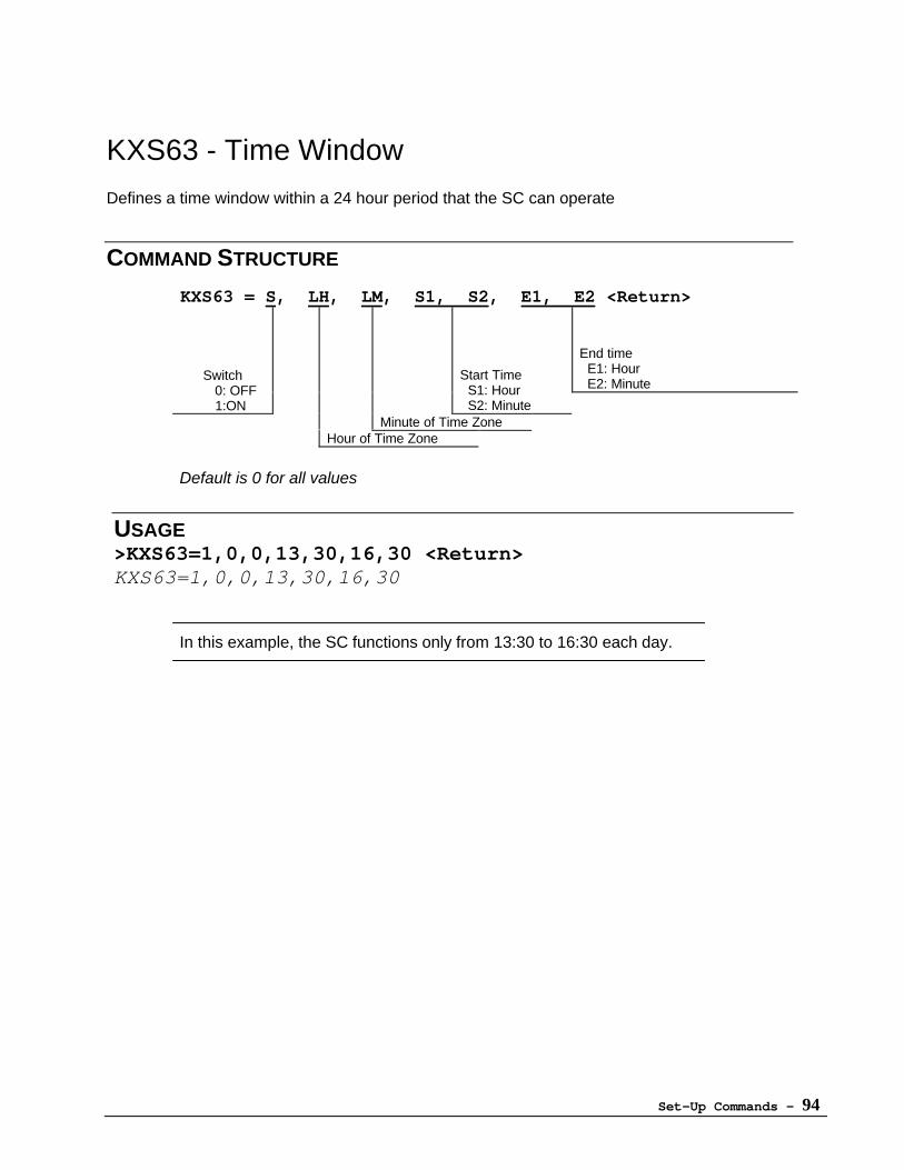
Set-Up Commands - 94
KXS63 - Time Window
Defines a time window within a 24 hour period that the SC can operate
COMMAND STRUCTURE
KXS63 = S, LH, LM, S1, S2, E1, E2 <Return>
End time E1: Hour E2: Minute
Switch 0: OFF
1:ON
Start Time S1: Hour S2: Minute
Minute of Time ZoneHour of Time Zone
Default is 0 for all values
USAGE>KXS63=1,0,0,13,30,16,30 <Return>KXS63=1,0,0,13,30,16,30
In this example, the SC functions only from 13:30 to 16:30 each day.
Set-Up Commands - 95
KXS64 - Quick Power Down
The Quick Power Down function will conserve power when using the KXB commands. When thefunction is activated (S=1), the SC will power down after message transmission.
When the Quick Power Down function is off (S=0), normal shut down times will be in effect.
COMMAND STRUCTUREKXS64 = S <Return>
0: = OFF (Power down 5 minutes after transmission)1: = ON (Power down immediately after transmission)Default is 0
USAGE>KXS64=1 <Return>KXS64=1
*** Important Notice ***
When using a User Application, the Quick Power Downfunction must be set to off (KXS64=0)
Set-Up Commands - 96
KXS65 - Position Transmission Mode
The SC will transmit a Position message to NCC automatically after calculating position whencontinuous position mode (KXS18=1) and a position calculation request is received from the DTE.
COMMAND STRUCTUREKXS65 = S <Return>
0: Not Send1: Auto SendDefault is 0
USAGE>KXS65=1 <Return>KXS65=1
If Continuous Position Determination Mode (KXS18) is set to 1 and KXS65=1,reports will be sent EVERY 2 MINUTES.
Position measurements using the KXA/KXB commands are NOT affected.
Set-Up Commands - 97
KXS66 - RAM Manager
Two blocks of RAM are available for application software. The first block of 4KBytes is alwaysavailable. To access the second block of 10KB, Doppler calculations must be deactivated.
The RAM Manager command allows the user to choose between increased user RAM (14KB, M=1)and no Doppler calculation or standard user RAM (4KB, M=0) and normal Doppler calculations.
COMMAND STRUCTUREKXS66 = M <Return>
0: 4KB RAM, Normal Doppler Calculation1: 14KB RAM, No Doppler CalculationDefault is 0
USAGE>KXS66=1 <Return>KXS66=1
Doppler calculation is deactivated when KXS66 =1.
User Application Program (UAP) must be loaded before KXS66 can be set to 1.
Setting KXS66=1 resets KXS21 (Minimum Quality Indicator for Doppler Positioning)to 0.
Set-Up Commands - 98
KXS67 - User Application Program Auto-Start
User Application Programs (UAPs) can be initiated at SC power up by activating this command(KXS67=1), provided a UAP is loaded in the SC.
COMMAND STRUCTUREKXS67 = S <Return>
0: Do not run UAP at SC power ON.1: Run UAP at SC power ON
Default is 0
USAGE>KXS67=1 <Return>KXS67=1
KXS67 can only be set to 1 when a UAP is loaded.
Set-Up Commands - 99
KXS68 - Serial Port Settings
The RS232C serial port can be managed by either the system or a User Application. When S=0,the SC controls the port. When S=1, the UAP assumes control.
COMMAND STRUCTUREKXS68 = S <Return>
0: Normal (Main system manages port)1: User Application manages port2: Reserved
Default is 0
USAGE>KXS68=1 <Return>KXS68=1
User applications must be loaded if KXS68 is set to 1. After user application usage,KXS68 must be set to 0 in order to achieve serial communication between the SCand DTE.
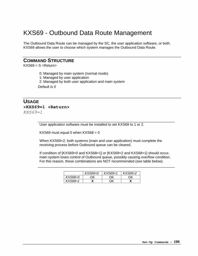
Set-Up Commands - 100
KXS69 - Outbound Data Route Management
The Outbound Data Route can be managed by the SC, the user application software, or both.KXS69 allows the user to choose which system manages the Outbound Data Route.
COMMAND STRUCTUREKXS69 = S <Return>
0: Managed by main system (normal mode)1: Managed by user application2: Managed by both user application and main system
Default is 0
USAGE>KXS69=1 <Return>KXS69=1
User application software must be installed to set KXS69 to 1 or 2.
KXS69 must equal 0 when KXS68 = 0
When KXS69=2, both systems (main and user application) must complete thereceiving process before Outbound queue can be cleared.
If condition of [KXS69=0 and KXS68=1] or [KXS69=2 and KXS68=1] should occur,main system loses control of Outbound queue, possibly causing overflow condition.For this reason, these combinations are NOT recommended (see table below).
KXS69=0 KXS69=1 KXS69=2KXS68=0 OK OK OKKXS68=1 X OK X
Set-Up Commands - 101
KXS70 - User Application Debug Mode
SC will output debug information to DTE when debug mode is set to ON.
COMMAND STRUCTUREKXS70 = S <Return>
0: Mode OFF1: Mode ON
Default is 0
USAGE>KXS70=1 <Return>KXS70=1
KXS70 can be set to 1 ONLY when a User Application is loaded.
Set-Up Commands - 102
KXS71 - Remote Configuration Password
A password can be created for added security when configuring the SC over the ORBCOMMnetwork. When activated, command parameters cannot be modified unless the password isappended to the end of the message. (See page 3 for more detail.)
Setting KXS71 to a value other than the default automatically activates the last four digits of theSC's serial number as a secondary password to the assigned password.
Four characters must be used to define the password. Valid characters are 0 to 9 and A to Z(capital letters only). Setting the password to “0000” disables this function.
COMMAND STRUCTUREKXS71 = CCCC <Return>
C: 4 characters (0-9, A-Z)Default is 0000
USAGE>KXS71=AZ90 <Return>KXS71=AZ90
Password is deactivated when KXS71 is “0000”.
Only KXS and the KXA/KXB commands can be changed remotely; userapplication software cannot.
Set-Up Commands - 103
KXS72 - Echo Remote Command Response
Return the ACK or NACK response after a remote configuration session to the default O/R indicator(per KXS05 - Default Message/GlobalGram Recipient).
COMMAND STRUCTUREKXS72 = D <Return>
0: No response1: Send response to default recipient
Default is 0
USAGE>KXS72=1 <Return>KXS72=1
When a command is entered correctly, body of the return email message will echothe sent command.:
KXS41=1
If the wrong command is entered, message body will contain an error message:
EER0

Set-Up Commands - 104
KXS73
[Reserved]
Set-Up Commands - 105
KXS74 - Message Transmission Mode
Select the message transmission mode for the KXA/KXB commands. SC can transmit the binarydata (KXS60=1) for each parameter (Position/Speed/Direction, Digital I/O Port and Analog Port)separately, or bundled together.
COMMAND STRUCTUREKXS74 = S <Return>
0 :Send apart1: Send bundled
Default is 0
USAGE>KXS74=1 <Return>KXS74=1
Sending data apart allows for quicker transmission of non-GPS related data, sinceGPS data requires additional time for position acquisition.
This command is effective when KXS60=1 (Binary message type)
Set-Up Commands - 106
KXS75 - Message Type Auto Change
KXA/KXB command or byte mode messages can automatically be changed to GlobalGrams whennormal messaging is not available.
COMMAND STRUCTUREKXS75 = S <Return>
0: Auto change to normal GlobalGram (not Enhanced GlobalGram)1: Don't change
Default is 1 (≥ Revision 4.x)Default is 0 on pre-Revision 4.x units.
USAGE>KXS75=1 <Return>KXS75=1
Set-Up Commands - 107
KXS76 - Satellite Elevation
Sets the minimum elevation angle (in degrees) that the SC will respond to by recalculating the waketime using satellite ephemeris data. Only wake portion (satellite entering view) of power ON cycleis affected by KXS76.
COMMAND STRUCTUREKXS76 = E <Return>
E: Elevation 0 – 45 [Degrees]Default is 5
USAGE>KXS76=10 <Return>KXS76=10
Under circumstances in which a building or mountain blocks the SC's line ofsight, using KXS76 allows the SC to ignore low satellite angles, therebyimproving system reliability and conserving power.
Set-Up Commands - 108
KXS77 - Message Body Transmission in Byte Mode
The message body can be transmitted to the DTE in either Protocol (packet) or Byte mode. Whenthis command is activated (S=1) the SC will transmit the body of the message to the DTE in Bytemode.
COMMAND STRUCTUREKXS77 = S <Return>
0: Normal (Protocol Mode)1: Byte mode (message body only)
Default is 0
USAGE>KXS77=1 <Return>KXS77=1
KXS77 is convenient for transmitting data or commands to a personal computer oranother communication device. This command only effects communication betweenthe personal computer (or other DTE) and SC.
This command effects only the message body. The subject, address and other partsof the message are always transmitted to the DTE in Normal (Protocol) mode.
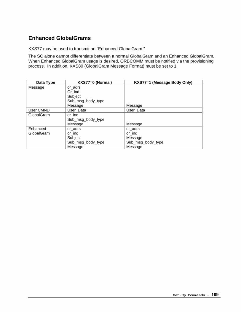
Set-Up Commands - 109
Enhanced GlobalGrams
KXS77 may be used to transmit an “Enhanced GlobalGram.”
The SC alone cannot differentiate between a normal GlobalGram and an Enhanced GlobalGram.When Enhanced GlobalGram usage is desired, ORBCOMM must be notified via the provisioningprocess. In addition, KXS80 (GlobalGram Message Format) must be set to 1.
Data Type KXS77=0 (Normal) KXS77=1 (Message Body Only)Message or_adrs
Or_indSubjectSub_msg_body_typeMessage Message
User CMND User_Data User_DataGlobalGram or_ind
Sub_msg_body_typeMessage Message
EnhancedGlobalGram
or_adrsor_indSubjectSub_msg_body_typeMessage
or_adrsor_indMessageSub_msg_body_typeMessage
Set-Up Commands - 110
KXS78 - Buffer Full Message
Activating the Buffer Full Message command (S=1) will cause the SC to transmit a “Buffer Full”message to the DTE. The buffer full message will be transmitted to the SC only in byte mode.
COMMAND STRUCTUREKXS78 = S <Return>
0: No message1: “Buffer Full” message
Default is 0
USAGE>KXS78=1 <Return>KXS78=1
The Buffer Full Message command can be used in conjunction with KXS45(Inbound Message Treatment) to assist the DTE in managing the inbound queue.
Set-Up Commands - 111
KXS79 - Event Timer
When using the Tracking (KXB) commands, the SC will wake up at the assigned time and wait for adesignated event. When the designated event meets the specified condition(s), the SC will performthe assigned function(s) and transmit.
The Event Timer command determines the period of time – in minutes – that the SC will wait for adesignated event. The SC will power down five minutes after this period has ended. (Refer to"Tracking Commands" section [page 19] for additional detail.)
Events are designated in KXB01, KXB02, and KXB03.
COMMAND STRUCTUREKXS79 = T <Return>
T: Time (5 - 20) [min]Default is 10
USAGE>KXS79=5 <Return>KXS79=5
Set-Up Commands - 112
KXS80 - GlobalGram Message Format
Selects the SC-terminated GlobalGram format. This parameter is referred to when the SC receivesGlobalGram data and KXS77 is set to 1.
COMMAND STRUCTUREKXS80 = S <Return>
0: GlobalGram1: Enhanced GlobalGram
Default is 0
USAGE>KXS80=1<return>KXS80=1
Set-Up Commands - 113
KXS81 - SC Terminated Message MMA (MaximumMSN Age)
(> Revision F)
Time interval after which the stored MSN (Message Sequence Number) becomes outdated. Oncea stored MSN becomes outdated, all messages delivered to the receiver will be considered newmessages, regardless of the MSN value.
COMMAND STRUCTUREKXS81 = T <Return>
T: Time (0-3932100) [sec]Default is 3600 (60 minutes)
USAGE>KXS81=1800 <Return>KXS81=1800
Use KXS81 to reduce duplication of messages.
Set-Up Commands - 114
KXS82 - SC Terminated GlobalGram MMA (MaximumMSN Age)
(> Revision F)
Time interval after which the stored MSN (Message Sequence Number) becomes outdated. Oncea stored MSN becomes outdated, all GlobalGrams delivered to the receiver will be considered newGlobalGrams, regardless of the MSN value.
COMMAND STRUCTUREKXS82 = T <Return>
T: Time (0-15300) [sec]Default is 300
USAGE>KXS82=600 <Return>KXS82=600
Use KXS82 to reduce duplication of messages.
Set-Up Commands - 115
KXS83 - Digital Output Default Value
(> Revision F)
Allows user to set the default level of the 2 digital output ports. Setting affects both ports.
COMMAND STRUCTUREKXS83 = V <Return>
0: Low1: High
Default is 1
USAGE>KXS83=0 <Return>KXS83=0
Set-Up Commands - 116
KXS84 - Roaming Capability
(> Revision F)
Selects type of roaming mode to be used by the SC. KXS84 and KXS85 (GCC ID of RoamingMode) allow for additional GCCs to be addressed along with the GCC selected by KXS01, allowingthe SC to be used in other parts of the world without resetting KXS01.
COMMAND STRUCTUREKXS84 = M <Return>
0:OFF (GCC selected by KXS01)1:ON (Send message to GCC as set by KXS85)2:ON (Allow satellite in view to determine destination GCC)
Default is 0
USAGE>KXS84=1 <Return>KXS84=1
SC must be registered with all desired GCCs through ORBCOMM.
Set-Up Commands - 117
KXS85 - GCC ID of Roaming Mode
(> Revision F)
Selects the GCC(s) to be used by the SC when KXS84=1. Up to 12 GCCs can be selected.
COMMAND STRUCTUREKXS85 = B, G <Return>
B: Block (0-11)G: GCC ID (0-255)Default is 0,0,0,0,0,0,0,0,0,0,0,0
USAGE>KXS85=0,120 <Return>KXS85=120,0,0,0,0,0,0,0,0,0,0,0>KXS85=1,121 <Return>KXS85=120,121,0,0,0,0,0,0,0,0,0,0>KXS85=2,123 <Return>KXS85=120,121,123,0,0,0,0,0,0,0,0,0>KXS85=3,130 <Return>KXS85=120,121,123,130,0,0,0,0,0,0,0,0
In this example, GCCs 120 (Italy), 121 (Malaysia), 123 (Brazil) and 130 (Japan) are stored inmemory blocks 0, 1, 2 and 3, respectively.
To delete a location, enter the memory block number and 0. For example, to delete the GCC inmemory block number 2:
>KXS85=2,0 <Return>KXS85=120,121,0,130,0,0,0,0,0,0,0,0
Set-Up Commands - 118
KXS86 - Day of the Week Mode
(> Revision F)
Messages created by the KXA/B commands (except for KXA06) can be sent on any or all days ofthe week. On days not selected, the message will not be created.
COMMAND STRUCTUREKXS86 = XXXXXXX <Return>
X: (0-1)
Each day is selected by setting the appropriate bit of the command code, as shown below.
1 0 1 0 1 0 1 Sun Mon Tues Wed Thu Fri Sat
0: Day not selected1: Day selectedDefault is 1 1 1 1 1 1 1
USAGE>KXS86=0101010 <Return>KXS86=0101010(Message will be sent Monday, Wednesday and Friday.)
Messages created on previous days that stall in inbound queue (e.g., no satellite)will still be sent as soon as possible, regardless of KXS86 setting.
On unselected days, the SC does NOT assume a "power off" mode. The unit willcontinue to cycle between sleep and wake cycles per the KXA/KXB commands.
Set-Up Commands - 119
KXS87 - GPS Quality Threshold
(> Revision 4.x)
The GPS Quality Threshold setting checks the PDOP (Position Dilution of Precision) value in eachdata string outputted by the GPS section in the SC. The SC then selects only the strings in whichthe LAT/LON data is under the assigned threshold.
COMMAND STRUCTUREKXS87 = T <Return>
T: Threshold (1-10)Default is 10
USAGE>KXS87=6 <Return>KXS87=6
The default setting of 10 allows for the best positional accuracy at the expenseof getting less data strings for calculation, due to the increased level of filteringinvolved. Therefore, when using the SC in "reduced signal" areas (e.g., citieswith tall buildings), it may be necessary to try a lower threshold value, since thedefault setting could result in a degradation of positioning performance.
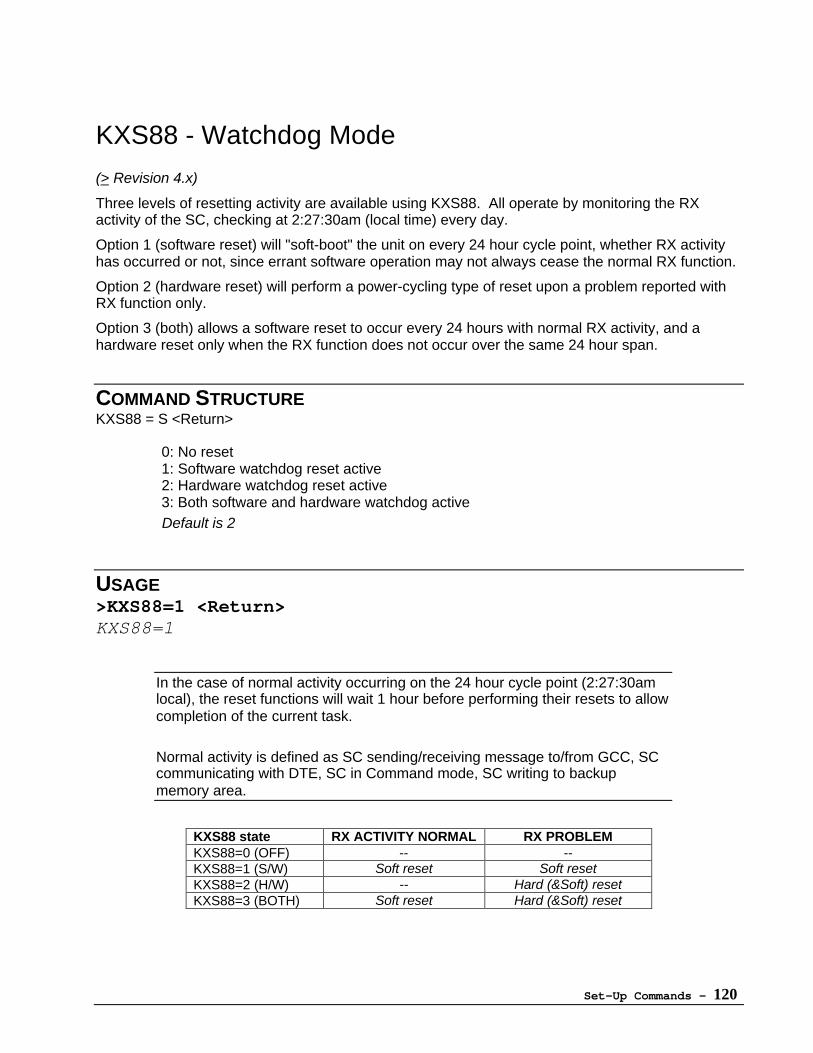
Set-Up Commands - 120
KXS88 - Watchdog Mode
(> Revision 4.x)
Three levels of resetting activity are available using KXS88. All operate by monitoring the RXactivity of the SC, checking at 2:27:30am (local time) every day.
Option 1 (software reset) will "soft-boot" the unit on every 24 hour cycle point, whether RX activityhas occurred or not, since errant software operation may not always cease the normal RX function.
Option 2 (hardware reset) will perform a power-cycling type of reset upon a problem reported withRX function only.
Option 3 (both) allows a software reset to occur every 24 hours with normal RX activity, and ahardware reset only when the RX function does not occur over the same 24 hour span.
COMMAND STRUCTUREKXS88 = S <Return>
0: No reset1: Software watchdog reset active2: Hardware watchdog reset active3: Both software and hardware watchdog activeDefault is 2
USAGE>KXS88=1 <Return>KXS88=1
In the case of normal activity occurring on the 24 hour cycle point (2:27:30amlocal), the reset functions will wait 1 hour before performing their resets to allowcompletion of the current task.
Normal activity is defined as SC sending/receiving message to/from GCC, SCcommunicating with DTE, SC in Command mode, SC writing to backupmemory area.
KXS88 state RX ACTIVITY NORMAL RX PROBLEMKXS88=0 (OFF) -- --KXS88=1 (S/W) Soft reset Soft resetKXS88=2 (H/W) -- Hard (&Soft) resetKXS88=3 (BOTH) Soft reset Hard (&Soft) reset
Set-Up Commands - 121
KXS00 - Get Values of All KXS Parameters
COMMAND STRUCTUREKXS00 <Return>
USAGE>KXS00 <Return>
KXS01 = 2KXS02 = 3KXS03 = 2
•••
KXS50 =3292KXS51 =1
•••
KXS86 = 0
Set-Up Commands - 122
Special Commands
KXM01 - Fixed Message
A fixed message can be sent using the Transmission (KXA) and Tracking (KXB) commands. UseKXM01 to define a fixed message up to 200 characters in length.
COMMAND STRUCTURE:
KXM01 = CCCCCCCCCCC----CC <Return>
Fixed message(maximum 200 characters)
USAGE>KXM01=HELLO <Return>KXM01=HELLO
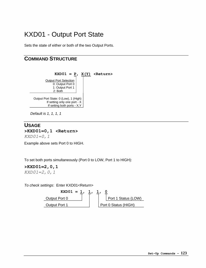
Set-Up Commands - 123
KXD01 - Output Port State
Sets the state of either or both of the two Output Ports.
COMMAND STRUCTURE
KXD01 = P, X(Y) <Return>
Output Port Selection0: Output Port 01: Output Port 1
2: Both
Output Port State: 0 (Low), 1 (High)If setting only one port - XIf setting both ports - X,Y
Default is 1, 1, 1, 1
USAGE>KXD01=0,1 <Return>KXD01=0,1
Example above sets Port 0 to HIGH.
To set both ports simultaneously (Port 0 to LOW, Port 1 to HIGH):
>KXD01=2,0,1KXD01=2,0,1
To check settings: Enter KXD01<Return>
KXD01 = 1, 1, 1, 0
Output Port 0 Port 1 Status (LOW)
Output Port 1 Port 0 Status (HIGH)
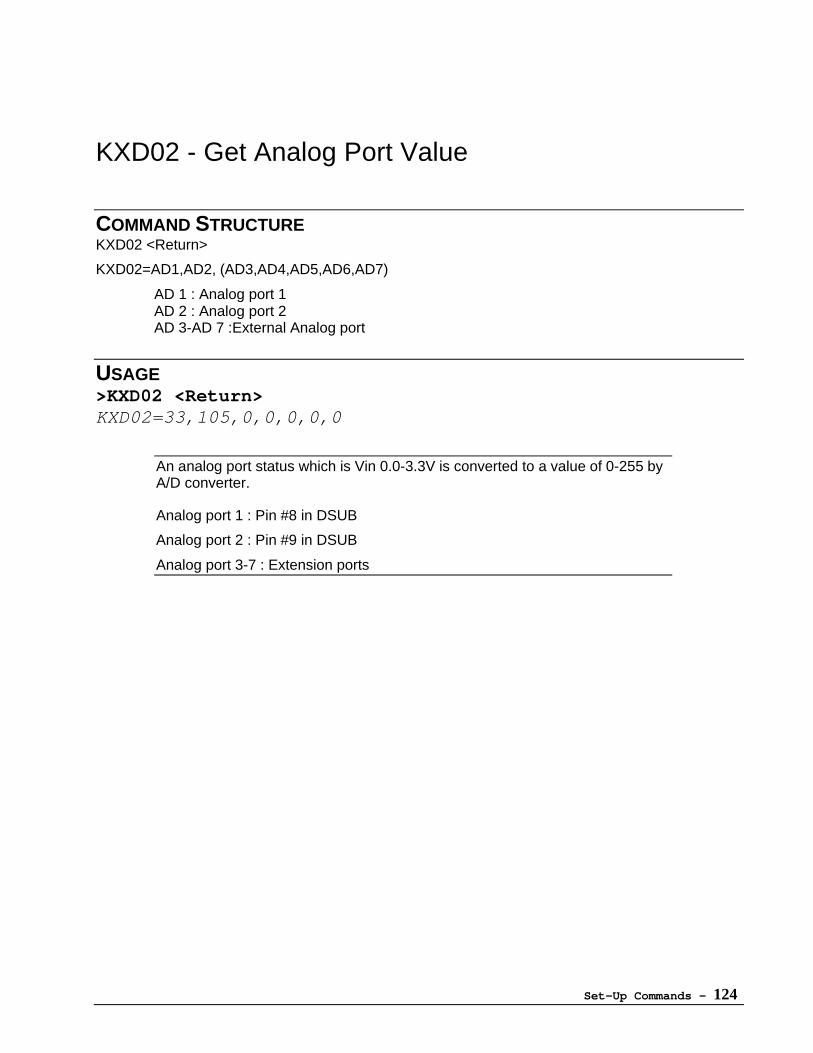
Set-Up Commands - 124
KXD02 - Get Analog Port Value
COMMAND STRUCTUREKXD02 <Return>
KXD02=AD1,AD2, (AD3,AD4,AD5,AD6,AD7)
AD 1 : Analog port 1AD 2 : Analog port 2AD 3-AD 7 :External Analog port
USAGE>KXD02 <Return>KXD02=33,105,0,0,0,0,0
An analog port status which is Vin 0.0-3.3V is converted to a value of 0-255 byA/D converter.
Analog port 1 : Pin #8 in DSUB
Analog port 2 : Pin #9 in DSUB
Analog port 3-7 : Extension ports
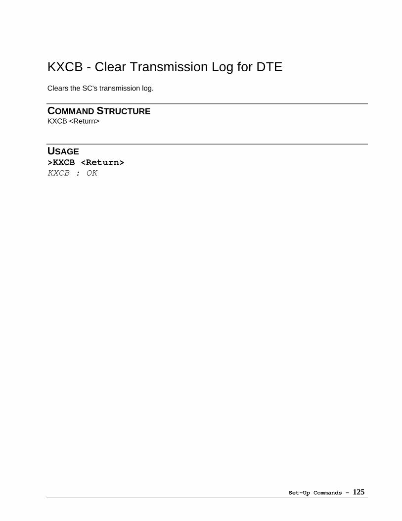
Set-Up Commands - 125
KXCB - Clear Transmission Log for DTE
Clears the SC's transmission log.
COMMAND STRUCTUREKXCB <Return>
USAGE>KXCB <Return>KXCB : OK
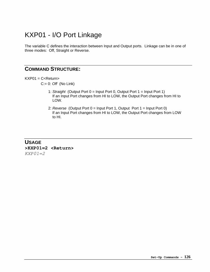
Set-Up Commands - 126
KXP01 - I/O Port Linkage
The variable C defines the interaction between Input and Output ports. Linkage can be in one ofthree modes: Off, Straight or Reverse.
COMMAND STRUCTURE:
KXP01 = C<Return>C:= 0: Off (No Link)
1: Straight (Output Port 0 = Input Port 0, Output Port 1 = Input Port 1) If an Input Port changes from HI to LOW, the Output Port changes from HI to LOW.
2: Reverse (Output Port 0 = Input Port 1, Output Port 1 = Input Port 0) If an Input Port changes from HI to LOW, the Output Port changes from LOW to HI.
USAGE>KXP01=2 <Return>KXP01=2
Set-Up Commands - 127
KXIB - Clear Inbound Queue of SC
Clears the contents of the SC's Inbound Queue.
COMMAND STRUCTURE:
KXIB <Return>
The Inbound queue of the SC will be cleared.
USAGE>KXIB <Return>KXIB : OK

Set-Up Commands - 128
KXOB - Clear Outbound Queue of SC
Clears the contents of the SC's Outbound Queue.
COMMAND STRUCTURE:
KXOB <Return>
The Outbound queue of the SC will be cleared.
USAGE>KXOB <Return>KXOB : OK
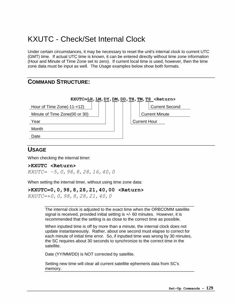
Set-Up Commands - 129
KXUTC - Check/Set Internal Clock
Under certain circumstances, it may be necessary to reset the unit's internal clock to current UTC(GMT) time. If actual UTC time is known, it can be entered directly without time zone information(Hour and Minute of Time Zone set to zero). If current local time is used, however, then the timezone data must be input as well. The Usage examples below show both formats.
COMMAND STRUCTURE:
KXUTC=LH,LM,DY,DM,DD,TH,TM,TS <Return>
Hour of Time Zone(-11-+12) Current Second
Minute of Time Zone(00 or 30) Current Minute
Year Current Hour
Month
Date
USAGE
When checking the internal timer:
>KXUTC <Return>KXUTC= -5,0,98,8,28,16,40,0
When setting the internal timer, without using time zone data:
>KXUTC=0,0,98,8,28,21,40,00 <Return>KXUTC=+0,0,98,8,28,21,40,0
The internal clock is adjusted to the exact time when the ORBCOMM satellitesignal is received, provided initial setting is +/- 60 minutes. However, it isrecommended that the setting is as close to the correct time as possible.
When inputted time is off by more than a minute, the internal clock does notupdate instantaneously. Rather, about one second must elapse to correct foreach minute of initial time error. So, if inputted time was wrong by 30 minutes,the SC requires about 30 seconds to synchronize to the correct time in thesatellite.
Date (YY/MM/DD) is NOT corrected by satellite.
Setting new time will clear all current satellite ephemeris data from SC'smemory.
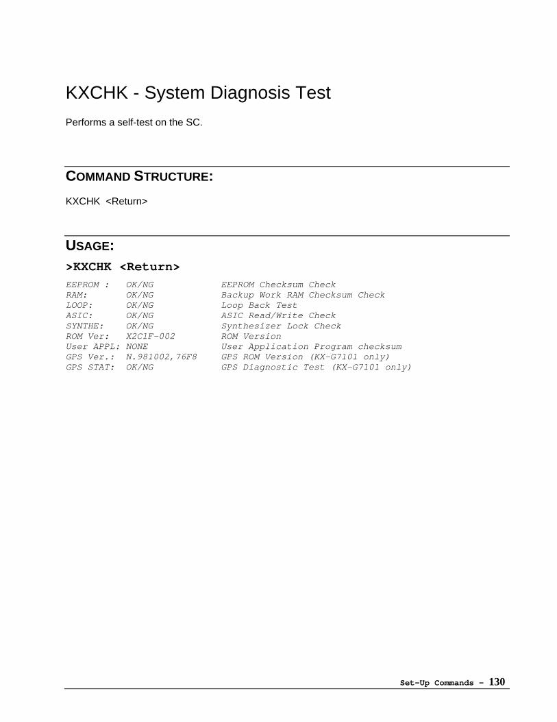
Set-Up Commands - 130
KXCHK - System Diagnosis Test
Performs a self-test on the SC.
COMMAND STRUCTURE:
KXCHK <Return>
USAGE:>KXCHK <Return>
EEPROM : OK/NG EEPROM Checksum CheckRAM: OK/NG Backup Work RAM Checksum CheckLOOP: OK/NG Loop Back TestASIC: OK/NG ASIC Read/Write CheckSYNTHE: OK/NG Synthesizer Lock CheckROM Ver: X2C1F-002 ROM VersionUser APPL: NONE User Application Program checksumGPS Ver.: N.981002,76F8 GPS ROM Version (KX-G7101 only)GPS STAT: OK/NG GPS Diagnostic Test (KX-G7101 only)
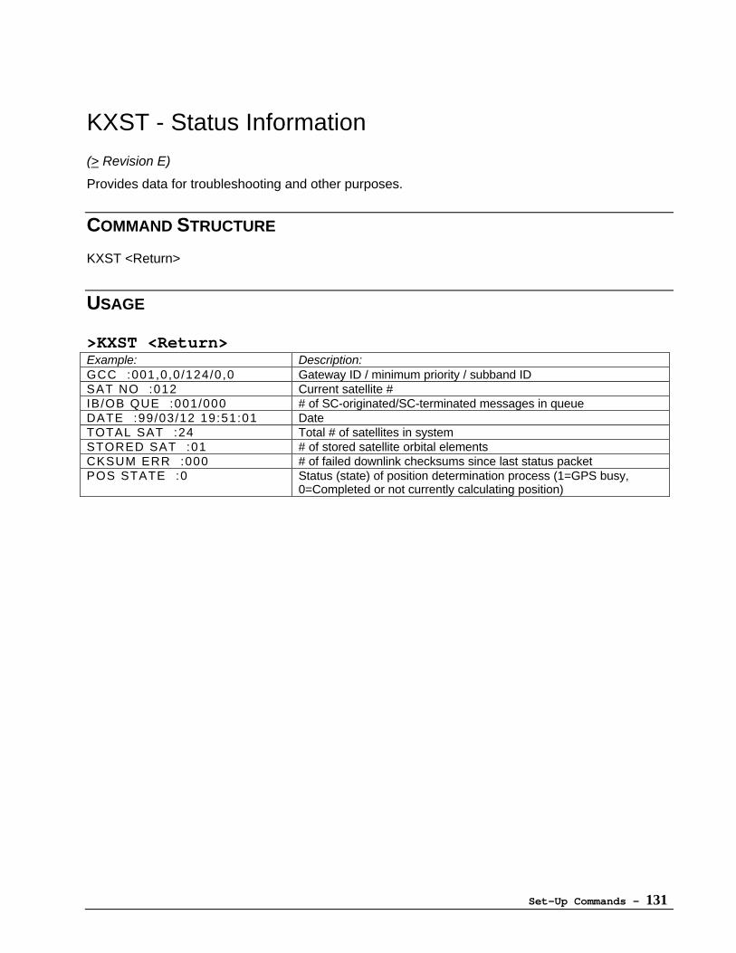
Set-Up Commands - 131
KXST - Status Information
(> Revision E)
Provides data for troubleshooting and other purposes.
COMMAND STRUCTURE
KXST <Return>
USAGE
>KXST <Return>Example: Description:GCC :001,0,0/124/0,0 Gateway ID / minimum priority / subband IDSAT NO :012 Current satellite #IB/OB QUE :001/000 # of SC-originated/SC-terminated messages in queueDATE :99/03/12 19:51:01 DateTOTAL SAT :24 Total # of satellites in systemSTORED SAT :01 # of stored satellite orbital elementsCKSUM ERR :000 # of failed downlink checksums since last status packetPOS STATE :0 Status (state) of position determination process (1=GPS busy,
0=Completed or not currently calculating position)
Set-Up Commands - 132
KXLED - Satellite in View LED
(> Revision E)
When active, allows for visual confirmation of a satellite's presence.
COMMAND STRUCTUREKXLED=N <Return>
N=0 Non-activeN=1 Active (LED lights when satellite is in view)N=2 Active (LED blinks while searching for satellite, stays lit when satellite is in view)
[N=2, > Revision F ]Default is 0
USAGE>KXLED=1 <Return>KXLED=1
It is recommended that this command is used only for testing purposes,since increased battery consumption will result.
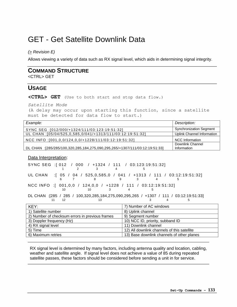
Set-Up Commands - 133
GET - Get Satellite Downlink Data
(> Revision E)
Allows viewing a variety of data such as RX signal level, which aids in determining signal integrity.
COMMAND STRUCTURE<CTRL> GET
USAGE
<CTRL> GET (Use to both start and stop data flow.)
Satellite Mode(A delay may occur upon starting this function, since a satellitemust be detected for data flow to start.)
Example: Description:
SYNC SEG : [012/000/+1324/111/03:123:19:51:32] Synchronization SegmentUL CHAN : [05/04/525,0 ,585,0 /041/+1313/111/03:12:19:51:32] Uplink Channel Information
NCC INFO : [001,0 ,0 /124,0 ,0 /+1228/111/03:12:19:51:32] NCC Information
DL CHAN :[285/285/100,320,285,184,275,090,295,265/+1307/111/03:12:19:51:33]Downlink ChannelInformation
Data Interpretation:
SYNC SEG : [ 012 / 000 / +1324 / 111 / 03:123:19:51:32]1 2 3 4 5
UL CHAN : [ 05 / 04 / 525,0,585,0 / 041 / +1313 / 111 / 03:12:19:51:32]6 7 8 9 3 4 5
NCC INFO : [ 001,0,0 / 124,0,0 / +1228 / 111 / 03:12:19:51:32]10 10 3 4 5
DL CHAN :[285 / 285 / 100,320,285,184,275,090,295,265 / +1307 / 111 / 03:12:19:51:33]11 12 13 3 4 5
KEY: 7) Number of AC windows1) Satellite number 8) Uplink channel2) Number of checksum errors in previous frames 9) Segment number3) Doppler frequency (Hz) 10) NCC ID, priority, subband ID4) RX signal level 11) Downlink channel5) Time 12) All downlink channels of this satellite6) Maximum retries 13) Base downlink channels of other planes
RX signal level is determined by many factors, including antenna quality and location, cabling,weather and satellite angle. If signal level does not achieve a value of 85 during repeatedsatellite passes, these factors should be considered before sending a unit in for service.
Set-Up Commands - 134
KXNCK - Channel Noise Check
(> Revision 4.x)
In some situations, it may be beneficial to know the receive signal level by individual channel.The KXNCK command allows the user to select any receive channel between 1-399 for monitoring.
COMMAND STRUCTUREKXNCK=M, C, O <Return>
M: Mode1: RSSI2-9: Reserved
C: RX Channel (1 - 399)O: Offset (Hz)
USAGE>KXNCK=1,350,0 <Return>RSSI : CH = 350 / Offset +0 [Hz]
EXIT : ESC KEY
> 58> 58> 54> 47> 54> 57> 55…etc.
To monitor noise, use channel 350 -- currently not used by ORBCOMM. ifindicated level is greater than 80, noise is considered excessive. Checkantenna location, external RF interference sources, etc. for possible cause.
Set-Up Commands - 135
Default Configuration
Set All Configuration Parameters to Factory Default Value
COMMAND STRUCTURE
CTRL + “D E F” <Return>
Set-Up Commands - 136
Default Baud Rate
Set RS-232C Baud Rate to Default (4800 bps)
This command is used when the setting of RS232C parameters of the SC is unknown, and the SCcannot communicate with the DTE.
COMMAND STRUCTURE
Keep pressing key “A” while you Power on the SC
or
Type “AAA” 1 second after the SC powers ON
Appendices - 137
Appendices
Appendix A: Understanding the Modes of Operation
The ORBCOMM Command SetThe ORBCOMM command set uses two serial port interface modes for communication: the primaryProtocol mode, and Byte mode.
Protocol modeIn Protocol mode, the communication between SC and DTE is based in the Serial InterfaceSpecification as prepared by ORBCOMM. The DTE can send and receive messages, reports,commands and "GlobalGrams", as well as obtain time-of-day and position estimates.
This is the SC's default mode of operation. If desired, the default can be changed to Byte Modeusing KXS31 (Operation Mode).
Byte modeByte mode is used primarily for direct-connection communication between the SC and PC/DTE. Inthis mode, data bytes are generated without header, length field, or checksum information, allowinga more efficient transfer of large messages. However, the transfers are less robust due to the lackof acknowledgements and checksums.
Configuring the SC to identify Byte mode data can be done by configuring these Panasoniccommands: KXS32 (Byte Mode Trigger), KXS33 (Byte Mode Timeout), KXS34 (Byte ModeLength), KXS35 (Byte Mode TX SOM/EOM, RX SOM/EOM).
The Panasonic Command SetThe Panasonic Command Set is designed to simplify the programming of the SC. Using its foursubsets (Transmission Commands, Tracking Commands, Setup Commands and SpecialCommands), a user can configure the unit to perform almost any desired function within theORBCOMM system limits.
Furthermore, SC owners can develop their own highly specialized applications using Panasonic'sSoftware Developer's Kit (SDK). These User Application Programs (UAPs) begin as "C" codebased programs before being converted to a custom format for loading into the SC. Once loaded,the UAP resides in a dedicated 4KB block of memory, which can be increased to 14KB usingKXS66 (Ram Manager).
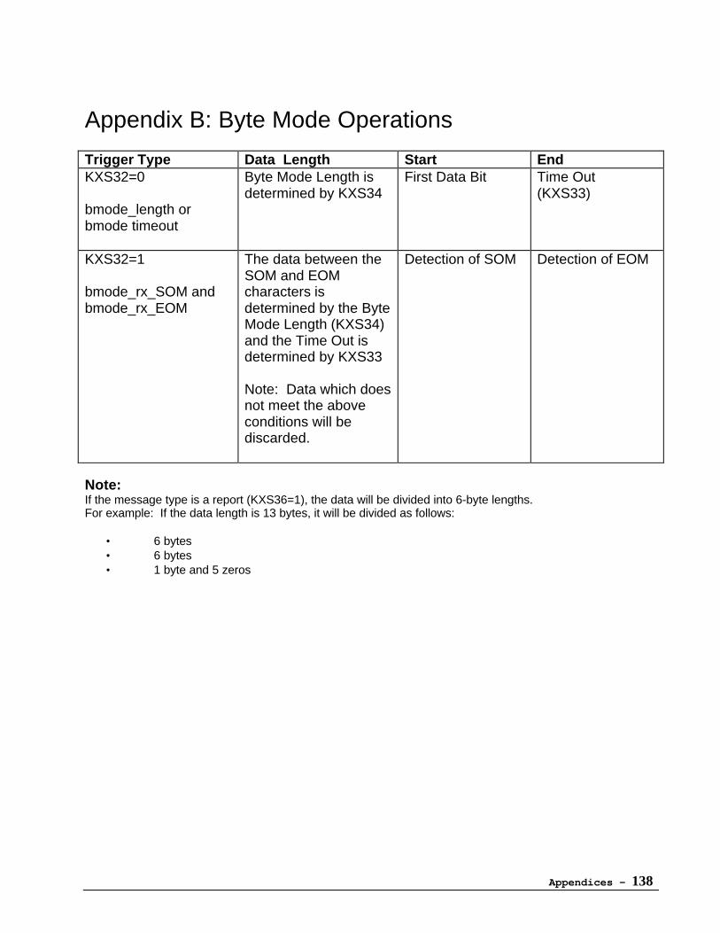
Appendices - 138
Appendix B: Byte Mode Operations
Trigger Type Data Length Start EndKXS32=0
bmode_length orbmode timeout
Byte Mode Length isdetermined by KXS34
First Data Bit Time Out(KXS33)
KXS32=1
bmode_rx_SOM andbmode_rx_EOM
The data between theSOM and EOMcharacters isdetermined by the ByteMode Length (KXS34)and the Time Out isdetermined by KXS33
Note: Data which doesnot meet the aboveconditions will bediscarded.
Detection of SOM Detection of EOM
Note:If the message type is a report (KXS36=1), the data will be divided into 6-byte lengths.For example: If the data length is 13 bytes, it will be divided as follows:
• 6 bytes• 6 bytes• 1 byte and 5 zeros
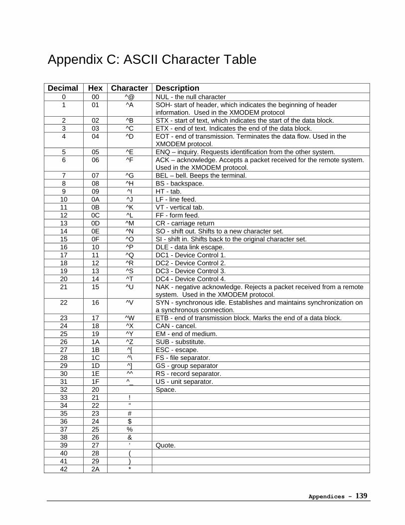
Appendices - 139
Appendix C: ASCII Character Table
Decimal Hex Character Description0 00 ^@ NUL - the null character1 01 ^A SOH- start of header, which indicates the beginning of header
information. Used in the XMODEM protocol2 02 ^B STX - start of text, which indicates the start of the data block.3 03 ^C ETX - end of text. Indicates the end of the data block.4 04 ^D EOT - end of transmission. Terminates the data flow. Used in the
XMODEM protocol.5 05 ^E ENQ – inquiry. Requests identification from the other system.6 06 ^F ACK – acknowledge. Accepts a packet received for the remote system.
Used in the XMODEM protocol.7 07 ^G BEL – bell. Beeps the terminal.8 08 ^H BS - backspace.9 09 ^I HT - tab.
10 0A ^J LF - line feed.11 0B ^K VT - vertical tab.12 0C ^L FF - form feed.13 0D ^M CR - carriage return14 0E ^N SO - shift out. Shifts to a new character set.15 0F ^O SI - shift in. Shifts back to the original character set.16 10 ^P DLE - data link escape.17 11 ^Q DC1 - Device Control 1.18 12 ^R DC2 - Device Control 2.19 13 ^S DC3 - Device Control 3.20 14 ^T DC4 - Device Control 4.21 15 ^U NAK - negative acknowledge. Rejects a packet received from a remote
system. Used in the XMODEM protocol.22 16 ^V SYN - synchronous idle. Establishes and maintains synchronization on
a synchronous connection.23 17 ^W ETB - end of transmission block. Marks the end of a data block.24 18 ^X CAN - cancel.25 19 ^Y EM - end of medium.26 1A ^Z SUB - substitute.27 1B ^[ ESC - escape.28 1C ^\ FS - file separator.29 1D ^] GS - group separator30 1E ^^ RS - record separator.31 1F ^_ US - unit separator.32 20 Space.33 21 !34 22 “35 23 #36 24 $37 25 %38 26 &39 27 ‘ Quote.40 28 (41 29 )42 2A *
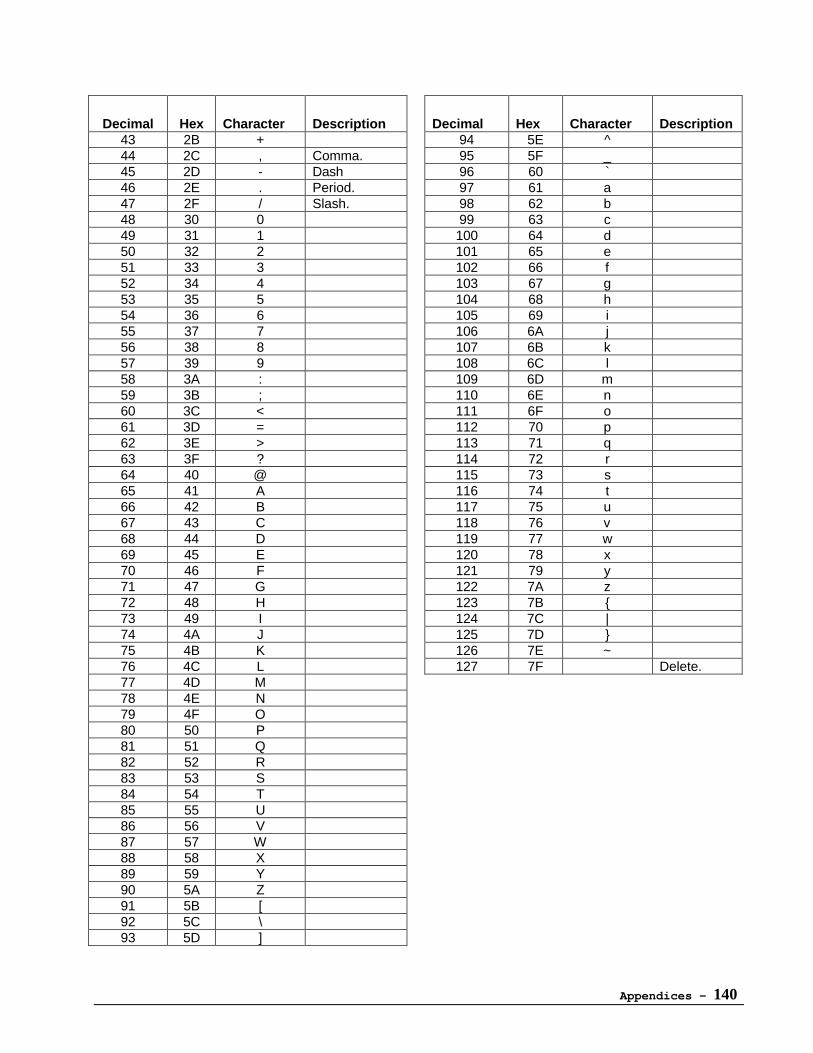
Appendices - 140
Decimal Hex Character Description Decimal Hex Character Description43 2B + 94 5E ^44 2C , Comma. 95 5F _45 2D - Dash 96 60 `46 2E . Period. 97 61 a47 2F / Slash. 98 62 b48 30 0 99 63 c49 31 1 100 64 d50 32 2 101 65 e51 33 3 102 66 f52 34 4 103 67 g53 35 5 104 68 h54 36 6 105 69 i55 37 7 106 6A j56 38 8 107 6B k57 39 9 108 6C l58 3A : 109 6D m59 3B ; 110 6E n60 3C < 111 6F o61 3D = 112 70 p62 3E > 113 71 q63 3F ? 114 72 r64 40 @ 115 73 s65 41 A 116 74 t66 42 B 117 75 u67 43 C 118 76 v68 44 D 119 77 w69 45 E 120 78 x70 46 F 121 79 y71 47 G 122 7A z72 48 H 123 7B {73 49 I 124 7C |74 4A J 125 7D }75 4B K 126 7E ~76 4C L 127 7F Delete.77 4D M78 4E N79 4F O80 50 P81 51 Q82 52 R83 53 S84 54 T85 55 U86 56 V87 57 W88 58 X89 59 Y90 5A Z91 5B [92 5C \93 5D ]

Appendices - 141
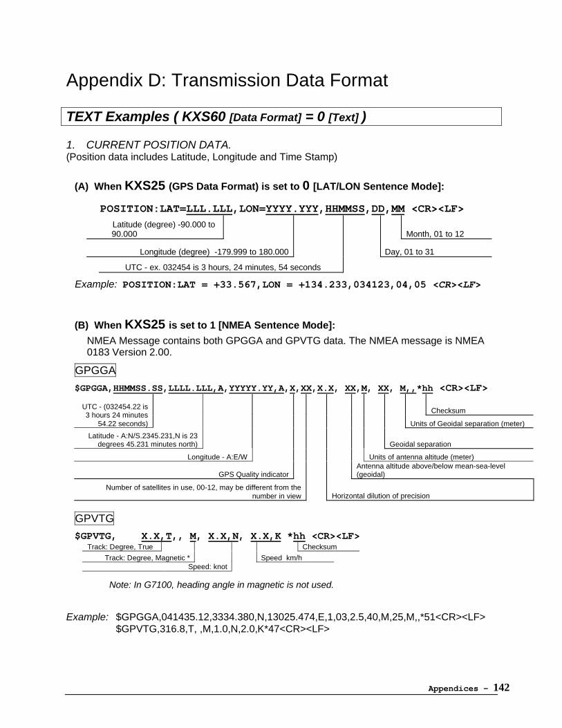
Appendices - 142
Appendix D: Transmission Data Format
TEXT Examples ( KXS60 [Data Format] = 0 [Text] )
1. CURRENT POSITION DATA.(Position data includes Latitude, Longitude and Time Stamp)
(A) When KXS25 (GPS Data Format) is set to 0 [LAT/LON Sentence Mode]:
POSITION:LAT=LLL.LLL,LON=YYYY.YYY,HHMMSS,DD,MM <CR><LF>
Latitude (degree) -90.000 to90.000 Month, 01 to 12
Longitude (degree) -179.999 to 180.000 Day, 01 to 31
UTC - ex. 032454 is 3 hours, 24 minutes, 54 seconds
Example: POSITION:LAT = +33.567,LON = +134.233,034123,04,05 <CR><LF>
(B) When KXS25 is set to 1 [NMEA Sentence Mode]:
NMEA Message contains both GPGGA and GPVTG data. The NMEA message is NMEA0183 Version 2.00.
GPGGA
$GPGGA,HHMMSS.SS,LLLL.LLL,A,YYYYY.YY,A,X,XX,X.X, XX,M, XX, M,,*hh <CR><LF>
ChecksumUTC - (032454.22 is3 hours 24 minutes
54.22 seconds) Units of Geoidal separation (meter)
Latitude - A:N/S.2345.231,N is 23degrees 45.231 minutes north) Geoidal separation
Longitude - A:E/W Units of antenna altitude (meter)
GPS Quality indicatorAntenna altitude above/below mean-sea-level(geoidal)
Number of satellites in use, 00-12, may be different from thenumber in view Horizontal dilution of precision
GPVTG
$GPVTG, X.X,T,, M, X.X,N, X.X,K *hh <CR><LF>Track: Degree, True Checksum
Track: Degree, Magnetic * Speed km/hSpeed: knot
Note: In G7100, heading angle in magnetic is not used.
Example: $GPGGA,041435.12,3334.380,N,13025.474,E,1,03,2.5,40,M,25,M,,*51<CR><LF>$GPVTG,316.8,T, ,M,1.0,N,2.0,K*47<CR><LF>
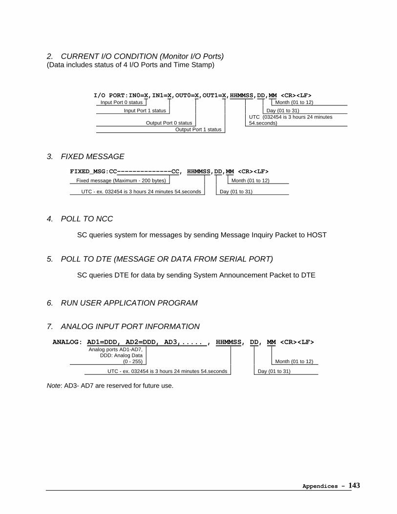
Appendices - 143
2. CURRENT I/O CONDITION (Monitor I/O Ports)(Data includes status of 4 I/O Ports and Time Stamp)
I/O PORT:IN0=X,IN1=X,OUT0=X,OUT1=X,HHMMSS,DD,MM <CR><LF>Input Port 0 status Month (01 to 12)
Input Port 1 status Day (01 to 31)
Output Port 0 statusUTC (032454 is 3 hours 24 minutes54.seconds)
Output Port 1 status
3. FIXED MESSAGE
FIXED_MSG:CC--------------CC, HHMMSS,DD,MM <CR><LF>Fixed message (Maximum - 200 bytes) Month (01 to 12)
UTC - ex. 032454 is 3 hours 24 minutes 54.seconds Day (01 to 31)
4. POLL TO NCC
SC queries system for messages by sending Message Inquiry Packet to HOST
5. POLL TO DTE (MESSAGE OR DATA FROM SERIAL PORT)
SC queries DTE for data by sending System Announcement Packet to DTE
6. RUN USER APPLICATION PROGRAM
7. ANALOG INPUT PORT INFORMATION
ANALOG: AD1=DDD, AD2=DDD, AD3,..... , HHMMSS, DD, MM <CR><LF>Analog ports AD1-AD7,
DDD: Analog Data(0 - 255) Month (01 to 12)
UTC - ex. 032454 is 3 hours 24 minutes 54.seconds Day (01 to 31)
Note: AD3- AD7 are reserved for future use.
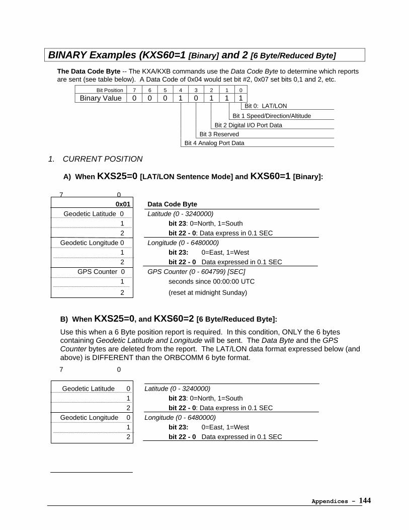
Appendices - 144
BINARY Examples (KXS60=1 [Binary] and 2 [6 Byte/Reduced Byte]
The Data Code Byte -- The KXA/KXB commands use the Data Code Byte to determine which reportsare sent (see table below). A Data Code of 0x04 would set bit #2, 0x07 set bits 0,1 and 2, etc.
Bit Position 7 6 5 4 3 2 1 0
Binary Value 0 0 0 1 0 1 1 1Bit 0: LAT/LON
Bit 1 Speed/Direction/Altitude
Bit 2 Digital I/O Port Data
Bit 3 Reserved
Bit 4 Analog Port Data
1. CURRENT POSITION
A) When KXS25=0 [LAT/LON Sentence Mode] and KXS60=1 [Binary]: 7 0
0x01 Data Code Byte Geodetic Latitude 0 Latitude (0 - 3240000)
1 bit 23: 0=North, 1=South2 bit 22 - 0: Data express in 0.1 SEC
Geodetic Longitude 0 Longitude (0 - 6480000)1 bit 23: 0=East, 1=West2 bit 22 - 0 Data expressed in 0.1 SEC
GPS Counter 0 GPS Counter (0 - 604799) [SEC]
1 seconds since 00:00:00 UTC
2 (reset at midnight Sunday)
B) When KXS25=0, and KXS60=2 [6 Byte/Reduced Byte]:
Use this when a 6 Byte position report is required. In this condition, ONLY the 6 bytescontaining Geodetic Latitude and Longitude will be sent. The Data Byte and the GPSCounter bytes are deleted from the report. The LAT/LON data format expressed below (andabove) is DIFFERENT than the ORBCOMM 6 byte format.
7 0
Geodetic Latitude 0 Latitude (0 - 3240000) 1 bit 23: 0=North, 1=South
2 bit 22 - 0: Data express in 0.1 SECGeodetic Longitude 0 Longitude (0 - 6480000)
1 bit 23: 0=East, 1=West2 bit 22 - 0 Data expressed in 0.1 SEC
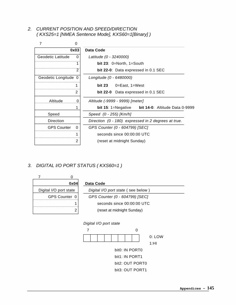
Appendices - 145
2. CURRENT POSITION AND SPEED/DIRECTION( KXS25=1 [NMEA Sentence Mode], KXS60=1[Binary] )
7 0
0x03 Data Code
Geodetic Latitude 0 Latitude (0 - 3240000)
1 bit 23: 0=North, 1=South
2 bit 22-0: Data expressed in 0.1 SEC
Geodetic Longitude 0 Longitude (0 - 6480000)
1 bit 23 0=East, 1=West
2 bit 22-0 Data expressed in 0.1 SEC
Altitude 0 Altitude (-9999 - 9999) [meter]
1 bit 15: 1=Negative bit 14-0: Altitude Data 0-9999
Speed Speed (0 - 255) [Km/h]
Direction Direction (0 - 180) expressed in 2 degrees at true.
GPS Counter 0 GPS Counter (0 - 604799) [SEC]
1 seconds since 00:00:00 UTC
2 (reset at midnight Sunday)
3. DIGITAL I/O PORT STATUS ( KXS60=1 )
7 0
0x04 Data Code
Digital I/O port state Digital I/O port state ( see below )
GPS Counter 0 GPS Counter (0 - 604799) [SEC]
1 seconds since 00:00:00 UTC
2 (reset at midnight Sunday)
Digital I/O port state
7 0
0: LOW
1:HI
bit0: IN PORT0
bit1: IN PORT1
bit2: OUT PORT0
bit3: OUT PORT1
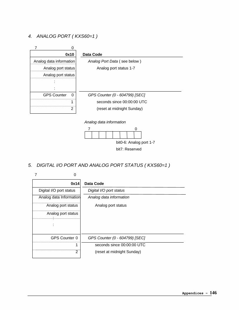
Appendices - 146
4. ANALOG PORT ( KXS60=1 )
7 0
0x10 Data Code
Analog data information Analog Port Data ( see below )
Analog port status Analog port status 1-7
Analog port status
:
:
GPS Counter 0 GPS Counter (0 - 604799) [SEC]
1 seconds since 00:00:00 UTC
2 (reset at midnight Sunday)
Analog data information
7 0
bit0-6: Analog port 1-7
bit7: Reserved
5. DIGITAL I/O PORT AND ANALOG PORT STATUS ( KXS60=1 )
7 0 0x14 Data Code
Digital I/O port status Digital I/O port status
Analog data Information Analog data information
Analog port status Analog port status
Analog port status:
:
GPS Counter 0 GPS Counter (0 - 604799) [SEC]
1 seconds since 00:00:00 UTC
2 (reset at midnight Sunday)
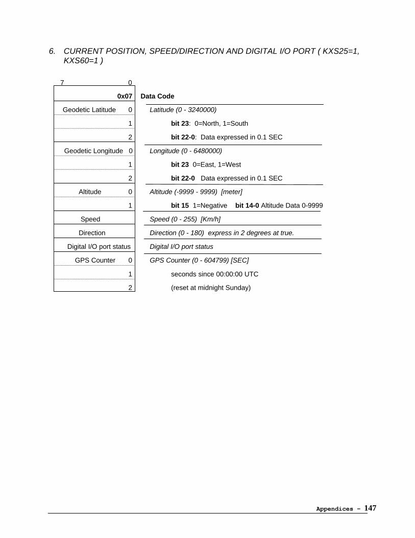
Appendices - 147
6. CURRENT POSITION, SPEED/DIRECTION AND DIGITAL I/O PORT ( KXS25=1,KXS60=1 )
7 0
0x07 Data Code
Geodetic Latitude 0 Latitude (0 - 3240000)
1 bit 23: 0=North, 1=South
2 bit 22-0: Data expressed in 0.1 SEC
Geodetic Longitude 0 Longitude (0 - 6480000)
1 bit 23 0=East, 1=West
2 bit 22-0 Data expressed in 0.1 SEC
Altitude 0 Altitude (-9999 - 9999) [meter]
1 bit 15 1=Negative bit 14-0 Altitude Data 0-9999
Speed Speed (0 - 255) [Km/h]
Direction Direction (0 - 180) express in 2 degrees at true.
Digital I/O port status Digital I/O port status
GPS Counter 0 GPS Counter (0 - 604799) [SEC]
1 seconds since 00:00:00 UTC
2 (reset at midnight Sunday)
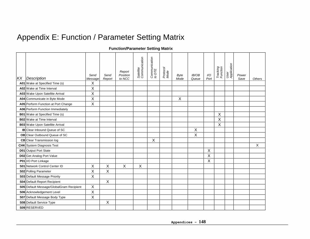
Appendices - 148
Appendix E: Function / Parameter Setting MatrixFunction/Parameter Setting Matrix
KX DescriptionSend
MessageSend
Report
ReportPositionto NCC S
atel
lite
Com
mun
icat
ion
Com
mun
icat
ion
to D
TE
Pro
toco
lM
ode
ByteMode
IB/OBQueue
I/OPort T
rack
ing
Fun
ctio
n
Use
rA
pplic
atio
n
PowerSave Others
A01 Wake at Specified Time (s) XA02 Wake at Time Interval XA03 Wake Upon Satellite Arrival XA04 Communicate in Byte Mode X XA05 Perform Function at Port Change XA06 Perform Function Immediately
B01 Wake at Specified Time (s) XB02 Wake at Time Interval XB03 Wake Upon Satellite Arrival X
IB Clear Inbound Queue of SC XOB Clear Outbound Queue of SC XCB Clear Transmission log X
CHK System Diagnosis Test X
D01 Output Port State XD02 Get Analog Port Value XP01 I/O Port Linkage XS01 Network Control Center ID X X X XS02 Polling Parameter X XS03 Default Message Priority XS04 Default Report Recipient XS05 Default Message/GlobalGram Recipient XS06 Acknowledgement Level XS07 Default Message Body Type XS08 Default Service Type XS09 RESERVED
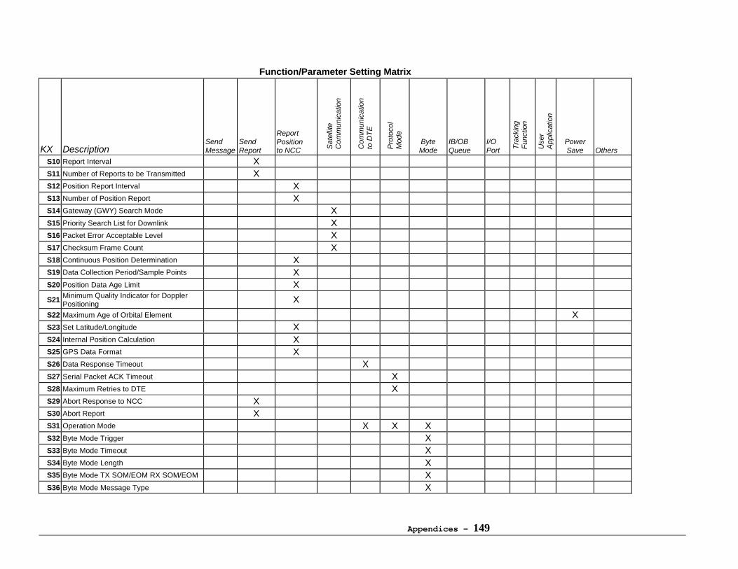
Appendices - 149
Function/Parameter Setting Matrix
KX DescriptionSendMessage
SendReport
ReportPositionto NCC S
atel
lite
Com
mun
icat
ion
Com
mun
icat
ion
to D
TE
Pro
toco
lM
ode
ByteMode
IB/OBQueue
I/OPort T
rack
ing
Fun
ctio
n
Use
rA
pplic
atio
n
PowerSave Others
S10 Report Interval XS11 Number of Reports to be Transmitted XS12 Position Report Interval XS13 Number of Position Report XS14 Gateway (GWY) Search Mode XS15 Priority Search List for Downlink XS16 Packet Error Acceptable Level XS17 Checksum Frame Count XS18 Continuous Position Determination XS19 Data Collection Period/Sample Points XS20 Position Data Age Limit X
S21 Minimum Quality Indicator for DopplerPositioning X
S22 Maximum Age of Orbital Element XS23 Set Latitude/Longitude XS24 Internal Position Calculation XS25 GPS Data Format XS26 Data Response Timeout XS27 Serial Packet ACK Timeout XS28 Maximum Retries to DTE XS29 Abort Response to NCC XS30 Abort Report XS31 Operation Mode X X XS32 Byte Mode Trigger XS33 Byte Mode Timeout XS34 Byte Mode Length XS35 Byte Mode TX SOM/EOM RX SOM/EOM XS36 Byte Mode Message Type X
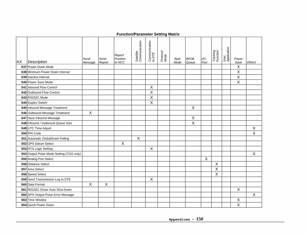
Appendices - 150
Function/Parameter Setting Matrix
KX DescriptionSendMessage
SendReport
ReportPositionto NCC S
atel
lite
Com
mun
icat
ion
Com
mun
icat
ion
to D
TE
Pro
toco
lM
ode
ByteMode
IB/OBQueue
I/OPort T
rack
ing
Fun
ctio
n
Use
rA
pplic
atio
n
PowerSave Others
S37 Power Down Mode XS38 Minimum Power Down Interval XS39 Inactive Interval XS40 Power Save Mode XS41 Inbound Flow Control XS42 Outbound Flow Control XS43 RS232C Mode XS44 Duplex Switch XS45 Inbound Message Treatment XS46 Outbound Message Treatment XS47 Save Inbound Message XS48 Inbound / Outbound Queue Size XS49 UTC Time Adjust XS50 PIN Code XS51 Automatic GlobalGram Polling XS52 GPS Datum Select XS53 RTS Logic Setting XS54 Output Pulse Mode Setting (7101 only) XS55 Analog Port Select XS56 Distance Select XS57 Area Select XS58 Speed Select XS59 Send Transmission Log to DTE XS60 Data Format X XS61 RS232C Driver Auto Shut Down XS62 GPS Output Pulse Error Message XS63 Time Window XS64 Quick Power Down X
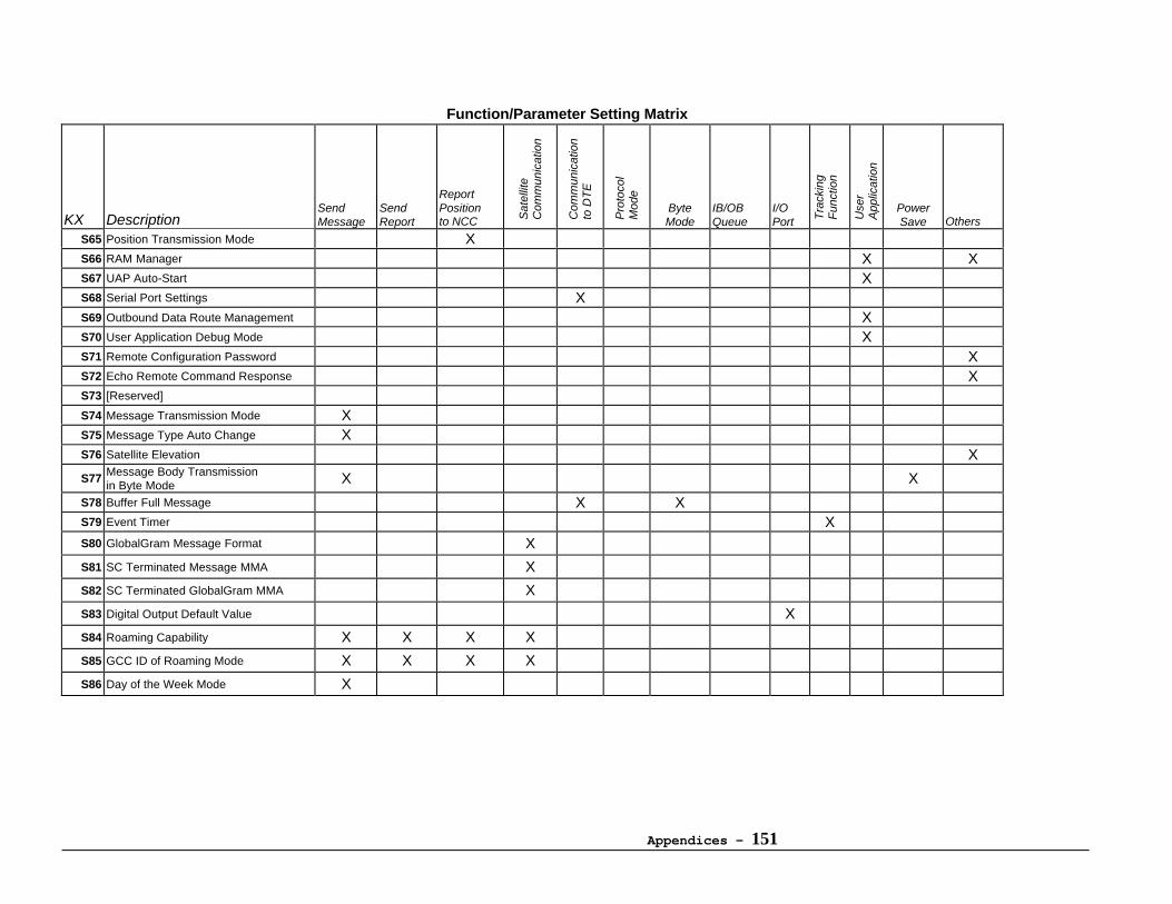
Appendices - 151
Function/Parameter Setting Matrix
KX DescriptionSendMessage
SendReport
ReportPositionto NCC S
atel
lite
Com
mun
icat
ion
Com
mun
icat
ion
to D
TE
Pro
toco
lM
ode
ByteMode
IB/OBQueue
I/OPort T
rack
ing
Fun
ctio
n
Use
rA
pplic
atio
n
PowerSave Others
S65 Position Transmission Mode XS66 RAM Manager X XS67 UAP Auto-Start XS68 Serial Port Settings XS69 Outbound Data Route Management XS70 User Application Debug Mode XS71 Remote Configuration Password XS72 Echo Remote Command Response XS73 [Reserved]
S74 Message Transmission Mode XS75 Message Type Auto Change XS76 Satellite Elevation X
S77 Message Body Transmissionin Byte Mode X X
S78 Buffer Full Message X XS79 Event Timer XS80 GlobalGram Message Format X
S81 SC Terminated Message MMA X
S82 SC Terminated GlobalGram MMA X
S83 Digital Output Default Value X
S84 Roaming Capability X X X X
S85 GCC ID of Roaming Mode X X X X
S86 Day of the Week Mode X

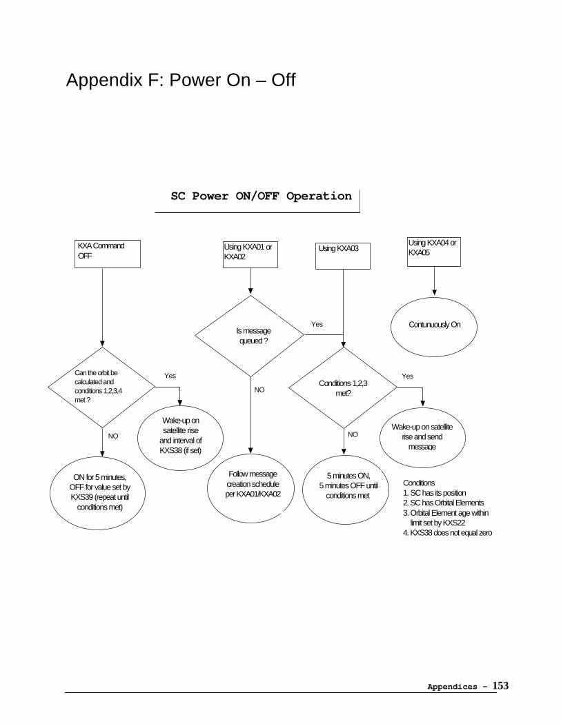
Appendices - 153
Appendix F: Power On – Off
Conditions1. SC has its position2. SC has Orbital Elements3. Orbital Element age within limit set by KXS224. KXS38 does not equal zero
Using KXA01 or KXA02
Using KXA04 or KXA05
KXA Command OFF
ON for 5 minutes, OFF for value set by KXS39 (repeat until
conditions met)
Wake-up on satellite rise
and interval of KXS38 (if set)
Follow message creation schedule per KXA01/KXA02
Contunuously On
5 minutes ON, 5 minutes OFF until
conditions met
Can the orbit be calculated andconditions 1,2,3,4 met ?
Is message queued ?
Conditions 1,2,3 met?
Wake-up on satellite rise and send
message
SC Power ON/OFF Operation
NO
Yes
NO
Yes
NO
Yes
Using KXA03

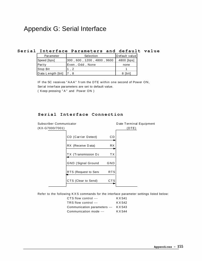
Appendices - 155
Appendix G: Serial Interface
Serial Interface Parameters and default valueParameter Selection D efault value
Speed [bps] 300 , 600 , 1200 , 4800 , 9600 4800 [bps]
Par i ty Even , Odd , None none
Stop Bit 1 , 2 1
D ata L ength [bit] 7 , 8 8 [bit]
IF the SC receives " A A A " f r om the DTE within one second of Pow er ON,
Ser ial inter face parameters are set to default value.
( Keep pressing " A " and Pow er ON )
Serial Interface Connection
Subscriber Communicator D ate T erminal Equipment
(KX-G7000/7001) (DTE)
CD (Carr ier D etect) CD
RX (Receive D ata) RX
T X (Transmission D ata) T X
GND (Signal Ground) G N D
RTS (Request to Send) RTS
CTS (Clear to Send) CTS
Refer to the following K X S commands for the interface parameter settings listed below:
CTS flow control --- K X S41
TRS flow control --- K X S42
Communication parameters --- K X S43
Communication mode --- K X S44


Appendices - 157
Appendix H: GPS Datum Table
In order to get precise positioning data, it may be necessary to use other mapping standards fordifferent countries or regions.
Caution
Each coordinate system is accurate ONLY in the assigned area. Unauthorized usage may result ina large position error.
Datum number 0 (WGS84 ) is recommended.
Default value is 0 “WGS84”
Datum # Coordinate System Region0 WGS84 World Geodetic System 19841 TOKYO [Japan, Korea, Okinawa]2 ADINDAN [Ethiopia, Mali, Senegal, Sudan]3 AFGOOYE [Somalia]4 AIN EL ABD 1970 [Bahrain Island]5 ANNA 1 ASTRO 1965 [Cocos Island]6 ARC 1950 [Botswana, Lesotho, Malawi, Swaziland,
Zaire, Zambia, Zimbabwe]7 ARC 1960 [Kenya, Tanzania]8 ASCENSION ISLAND 1958 [Ascension Island]9 ASTRO BEACON "E" [Iwo-Jima Island]
10 ASTRO B4 SOROL ATOLL [Tern Island]11 ASTRO DOS 71/4 [St. Helena Island]12 ASTORONOMIC STATION 1952 [Marcus Island]13 AUSTRALIAN GEODETIC 1966 [Australia, Tasmania]14 AUSTRALIAN GEODETIC 1984 [Australia, Tasmania]15 BELLEVUE(ING) [Efate, Erromango]16 BERMUDA 1957 [Bermuda Island]17 BOGOTA OBSERVATORY [Colombia]18 CAMPO INCHAUSPE [Argentina]19 CANTON ASTRO 1966 [Phoenix Island]20 CAPE [South Africa]21 CAPE_CANAVERAL [Florida, Bahamas]22 CARTHAGE [Tunisia]23 CHATHAM 1971 [Chatham Island]24 CHUA ASTRO [Paraguay]25 CORREGO ALEGRE [Brazil]26 DJAKARTA (BATAVIA) [Sumatra Island]27 DOS 1968 [Gizo Island]28 EASTER ISLAND 1967 [Easter Island]29 EUROPEAN_1950 [Austria, Belgium, Denmark, Finland,
France, German, Gibraltar, Greece,Italy, Luxembourg, Netherlands,Norway, Portugal, Spain, Sweden,Switzerland]
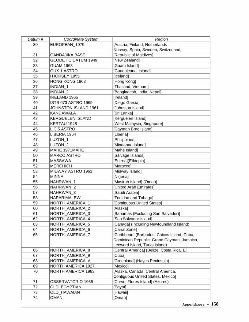
Appendices - 158
Datum # Coordinate System Region30 EUROPEAN_1979 [Austria, Finland, Netherlands
Norway, Spain, Sweden, Switzerland]31 GANDAJIKA BASE [Republic of Maldives]32 GEODETIC DATUM 1949 [New Zealand]33 GUAM 1963 [Guam Island]34 GUX 1 ASTRO [Guadalcanal Island]35 HJORSEY 1955 [Iceland]36 HONG KONG 1963 [Hong Kong]37 INDIAN_1 [Thailand, Vietnam]38 INDIAN_2 [Bangladesh, India, Nepal]39 IRELAND 1965 [Ireland]40 ISTS 073 ASTRO 1969 [Diego Garcia]41 JOHNSTON ISLAND 1961 [Johnston Island]42 KANDAWALA [Sri Lanka]43 KERGUELEN ISLAND [Kerguelen Island]44 KERTAU 1948 [West Malaysia, Singapore]45 L.C.5 ASTRO [Cayman Brac Island]46 LIBERIA 1964 [Liberia]47 LUZON_1 [Philippines]48 LUZON_2 [Mindanao Island]49 MAHE 1971MAHE [Mahe Island]50 MARCO ASTRO [Salvage Islands]51 MASSAWA [Eritrea](Ethiopia)52 MERCHICH [Morocco]53 MIDWAY ASTRO 1961 [Midway Island]54 MINNA [Nigeria]55 NAHRWAN_1 [Masirah Island] (Oman)56 NAHRWAN_2 [United Arab Emirates]57 NAHRWAN_3 [Saudi Arabia]58 NAPARIMA, BWI [Trinidad and Tobago]59 NORTH_AMERICA_1 [Contiguous United States]60 NORTH_AMERICA_2 [Alaska]61 NORTH_AMERICA_3 [Bahamas (Excluding San Salvador)]62 NORTH_AMERICA_4 [San Salvador Island]63 NORTH_AMERICA_5 [Canada] (Including Newfoundland Island)64 NORTH_AMERICA_6 [Canal Zone]65 NORTH_AMERICA_7 [Caribbean] (Barbados, Caicos Island, Cuba,
Dominican Republic, Grand Cayman, Jamaica,Leeward Island, Turks Island)
66 NORTH_AMERICA_8 [Central America] (Belize, Costa Rica, El67 NORTH_AMERICA_9 [Cuba]68 NORTH_AMERICA_A [Greenland] (Hayes Peninsula)69 NORTH AMERICA 1927 [Mexico]70 NORTH AMERICA 1983 [Alaska, Canada, Central America,
Contiguous United States, Mexico]71 OBSERVATORIO 1966 [Corvo, Flores Island] (Azores)72 OLD_EGYPTIAN [Egypt]73 OLD_HAWAIAN [Hawaii]74 OMAN [Oman]
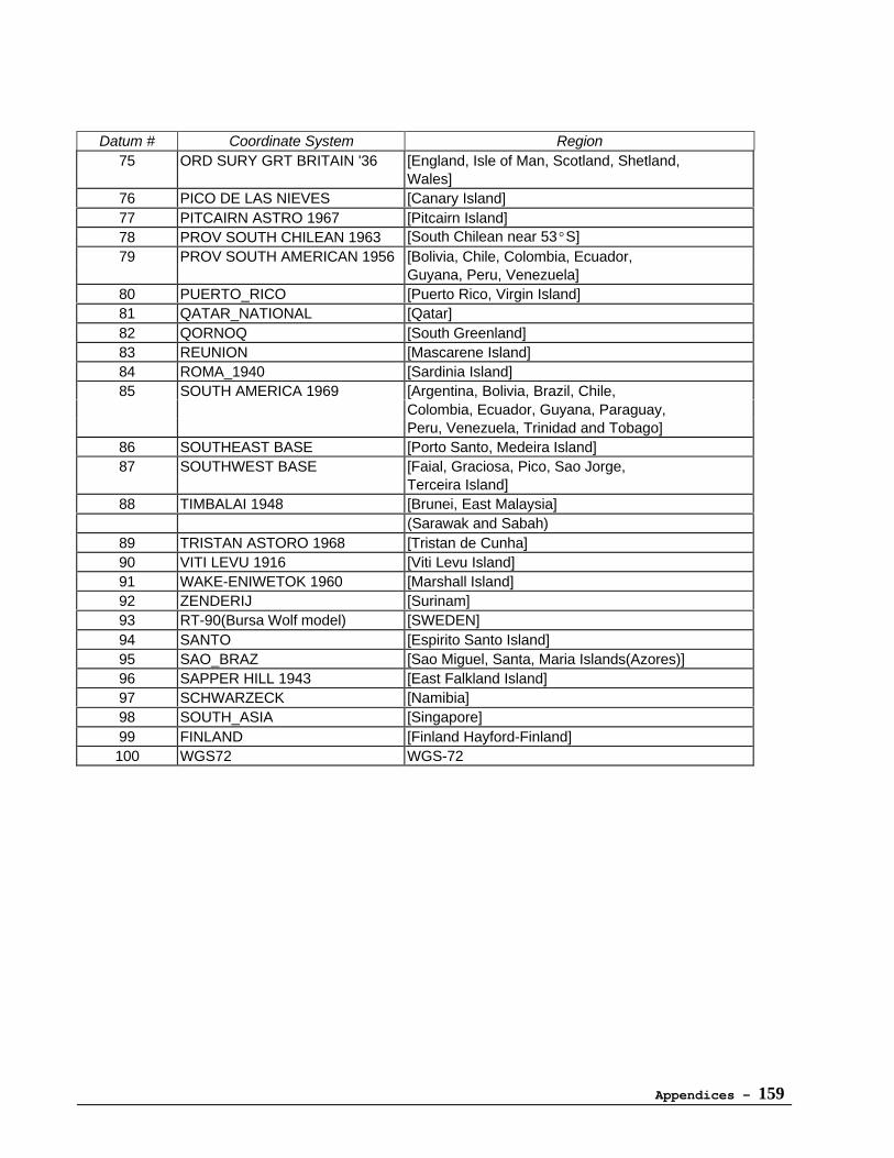
Appendices - 159
Datum # Coordinate System Region75 ORD SURY GRT BRITAIN '36 [England, Isle of Man, Scotland, Shetland,
Wales]76 PICO DE LAS NIEVES [Canary Island]77 PITCAIRN ASTRO 1967 [Pitcairn Island]78 PROV SOUTH CHILEAN 1963 [South Chilean near 53°S]79 PROV SOUTH AMERICAN 1956 [Bolivia, Chile, Colombia, Ecuador,
Guyana, Peru, Venezuela]80 PUERTO_RICO [Puerto Rico, Virgin Island]81 QATAR_NATIONAL [Qatar]82 QORNOQ [South Greenland]83 REUNION [Mascarene Island]84 ROMA_1940 [Sardinia Island]85 SOUTH AMERICA 1969 [Argentina, Bolivia, Brazil, Chile,
Colombia, Ecuador, Guyana, Paraguay,Peru, Venezuela, Trinidad and Tobago]
86 SOUTHEAST BASE [Porto Santo, Medeira Island]87 SOUTHWEST BASE [Faial, Graciosa, Pico, Sao Jorge,
Terceira Island]88 TIMBALAI 1948 [Brunei, East Malaysia]
(Sarawak and Sabah)89 TRISTAN ASTORO 1968 [Tristan de Cunha]90 VITI LEVU 1916 [Viti Levu Island]91 WAKE-ENIWETOK 1960 [Marshall Island]92 ZENDERIJ [Surinam]93 RT-90(Bursa Wolf model) [SWEDEN]94 SANTO [Espirito Santo Island]95 SAO_BRAZ [Sao Miguel, Santa, Maria Islands(Azores)]96 SAPPER HILL 1943 [East Falkland Island]97 SCHWARZECK [Namibia]98 SOUTH_ASIA [Singapore]99 FINLAND [Finland Hayford-Finland]100 WGS72 WGS-72
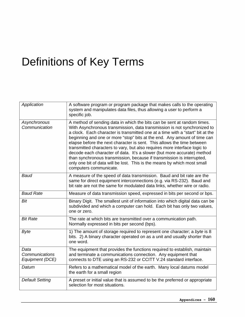
Appendices - 160
Definitions of Key Terms
Application A software program or program package that makes calls to the operatingsystem and manipulates data files, thus allowing a user to perform aspecific job.
AsynchronousCommunication
A method of sending data in which the bits can be sent at random times.With Asynchronous transmission, data transmission is not synchronized toa clock. Each character is transmitted one at a time with a “start” bit at thebeginning and one or more “stop” bits at the end. Any amount of time canelapse before the next character is sent. This allows the time betweentransmitted characters to vary, but also requires more interface logic todecode each character of data. It’s a slower (but more accurate) methodthan synchronous transmission, because if transmission is interrupted,only one bit of data will be lost. This is the means by which most smallcomputers communicate.
Baud A measure of the speed of data transmission. Baud and bit rate are thesame for direct equipment interconnections (e.g. via RS-232). Baud andbit rate are not the same for modulated data links, whether wire or radio.
Baud Rate Measure of data transmission speed, expressed in bits per second or bps.
Bit Binary Digit. The smallest unit of information into which digital data can besubdivided and which a computer can hold. Each bit has only two values,one or zero.
Bit Rate The rate at which bits are transmitted over a communication path.Normally expressed in bits per second (bps).
Byte 1) The amount of storage required to represent one character; a byte is 8bits. 2) A binary character operated on as a unit and usually shorter thanone word.
DataCommunicationsEquipment (DCE)
The equipment that provides the functions required to establish, maintainand terminate a communications connection. Any equipment thatconnects to DTE using an RS-232 or CCITT V.24 standard interface.
Datum Refers to a mathematical model of the earth. Many local datums modelthe earth for a small region
Default Setting A preset or initial value that is assumed to be the preferred or appropriateselection for most situations.
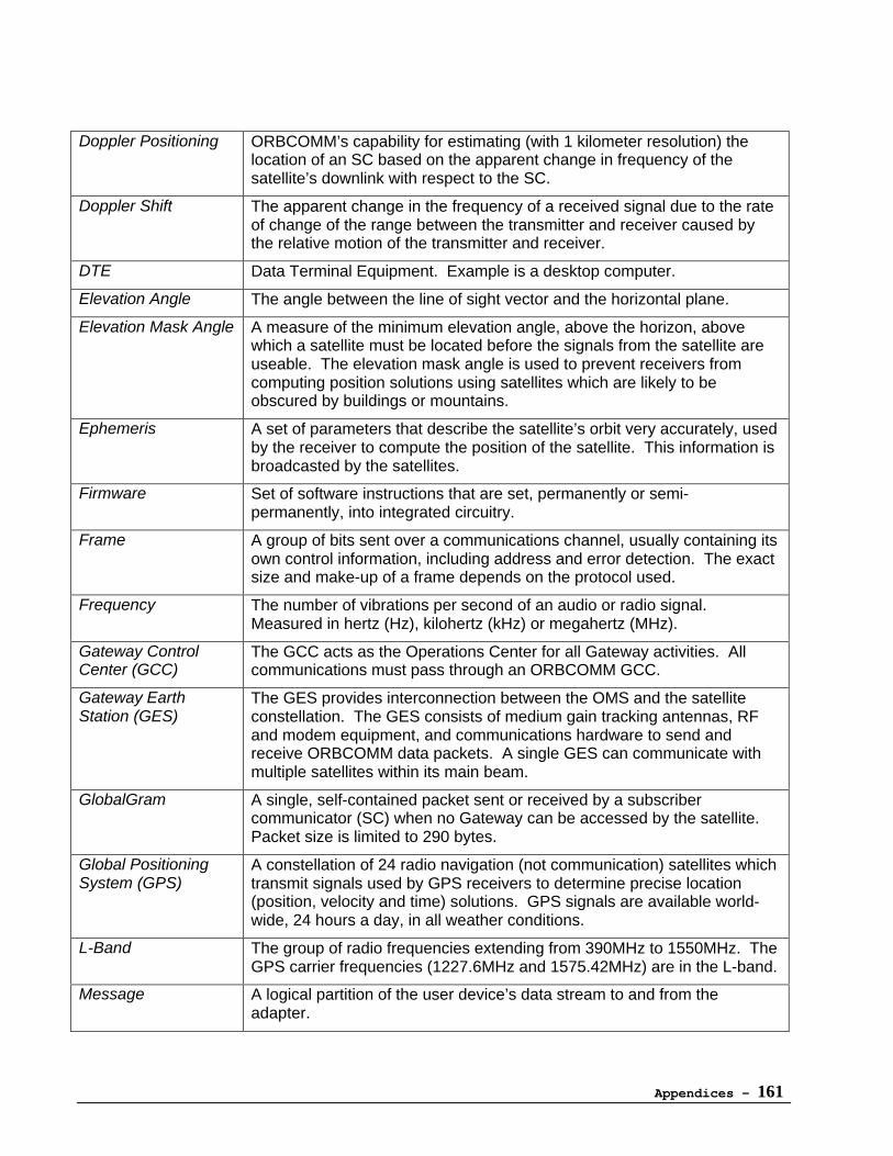
Appendices - 161
Doppler Positioning ORBCOMM’s capability for estimating (with 1 kilometer resolution) thelocation of an SC based on the apparent change in frequency of thesatellite’s downlink with respect to the SC.
Doppler Shift The apparent change in the frequency of a received signal due to the rateof change of the range between the transmitter and receiver caused bythe relative motion of the transmitter and receiver.
DTE Data Terminal Equipment. Example is a desktop computer.
Elevation Angle The angle between the line of sight vector and the horizontal plane.
Elevation Mask Angle A measure of the minimum elevation angle, above the horizon, abovewhich a satellite must be located before the signals from the satellite areuseable. The elevation mask angle is used to prevent receivers fromcomputing position solutions using satellites which are likely to beobscured by buildings or mountains.
Ephemeris A set of parameters that describe the satellite’s orbit very accurately, usedby the receiver to compute the position of the satellite. This information isbroadcasted by the satellites.
Firmware Set of software instructions that are set, permanently or semi-permanently, into integrated circuitry.
Frame A group of bits sent over a communications channel, usually containing itsown control information, including address and error detection. The exactsize and make-up of a frame depends on the protocol used.
Frequency The number of vibrations per second of an audio or radio signal.Measured in hertz (Hz), kilohertz (kHz) or megahertz (MHz).
Gateway ControlCenter (GCC)
The GCC acts as the Operations Center for all Gateway activities. Allcommunications must pass through an ORBCOMM GCC.
Gateway EarthStation (GES)
The GES provides interconnection between the OMS and the satelliteconstellation. The GES consists of medium gain tracking antennas, RFand modem equipment, and communications hardware to send andreceive ORBCOMM data packets. A single GES can communicate withmultiple satellites within its main beam.
GlobalGram A single, self-contained packet sent or received by a subscribercommunicator (SC) when no Gateway can be accessed by the satellite.Packet size is limited to 290 bytes.
Global PositioningSystem (GPS)
A constellation of 24 radio navigation (not communication) satellites whichtransmit signals used by GPS receivers to determine precise location(position, velocity and time) solutions. GPS signals are available world-wide, 24 hours a day, in all weather conditions.
L-Band The group of radio frequencies extending from 390MHz to 1550MHz. TheGPS carrier frequencies (1227.6MHz and 1575.42MHz) are in the L-band.
Message A logical partition of the user device’s data stream to and from theadapter.
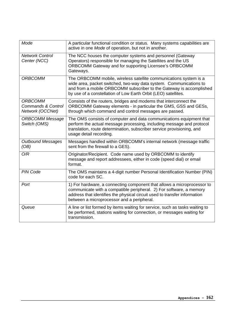
Appendices - 162
Mode A particular functional condition or status. Many systems capabilities areactive in one Mode of operation, but not in another.
Network ControlCenter (NCC)
The NCC houses the computer systems and personnel (GatewayOperators) responsible for managing the Satellites and the USORBCOMM Gateway and for supporting Licensee’s ORBCOMMGateways.
ORBCOMM The ORBCOMM mobile, wireless satellite communications system is awide area, packet switched, two-way data system. Communications toand from a mobile ORBCOMM subscriber to the Gateway is accomplishedby use of a constellation of Low Earth Orbit (LEO) satellites.
ORBCOMMCommands & ControlNetwork (OCCNet)
Consists of the routers, bridges and modems that interconnect theORBCOMM Gateway elements - in particular the GMS, GSS and GESs,through which command and control messages are passed.
ORBCOMM MessageSwitch (OMS)
The OMS consists of computer and data communications equipment thatperform the actual message processing, including message and protocoltranslation, route determination, subscriber service provisioning, andusage detail recording.
Outbound Messages(OB)
Messages handled within ORBCOMM’s internal network (message trafficsent from the firewall to a GES).
O/R Originator/Recipient. Code name used by ORBCOMM to identifymessage and report addressees, either in code (speed dial) or emailformat.
PIN Code The OMS maintains a 4-digit number Personal Identification Number (PIN)code for each SC.
Port 1) For hardware, a connecting component that allows a microprocessor tocommunicate with a compatible peripheral. 2) For software, a memoryaddress that identifies the physical circuit used to transfer informationbetween a microprocessor and a peripheral.
Queue A line or list formed by items waiting for service, such as tasks waiting tobe performed, stations waiting for connection, or messages waiting fortransmission.
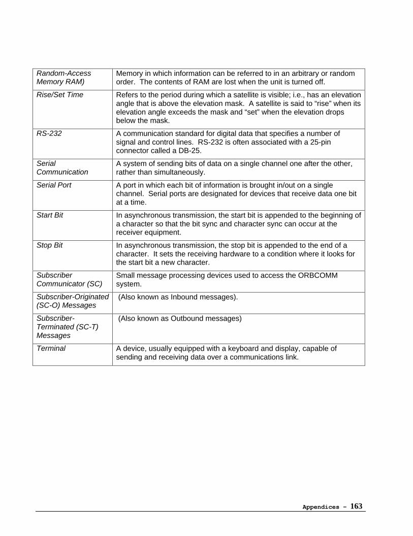
Appendices - 163
Random-AccessMemory RAM)
Memory in which information can be referred to in an arbitrary or randomorder. The contents of RAM are lost when the unit is turned off.
Rise/Set Time Refers to the period during which a satellite is visible; i.e., has an elevationangle that is above the elevation mask. A satellite is said to “rise” when itselevation angle exceeds the mask and “set” when the elevation dropsbelow the mask.
RS-232 A communication standard for digital data that specifies a number ofsignal and control lines. RS-232 is often associated with a 25-pinconnector called a DB-25.
SerialCommunication
A system of sending bits of data on a single channel one after the other,rather than simultaneously.
Serial Port A port in which each bit of information is brought in/out on a singlechannel. Serial ports are designated for devices that receive data one bitat a time.
Start Bit In asynchronous transmission, the start bit is appended to the beginning ofa character so that the bit sync and character sync can occur at thereceiver equipment.
Stop Bit In asynchronous transmission, the stop bit is appended to the end of acharacter. It sets the receiving hardware to a condition where it looks forthe start bit a new character.
SubscriberCommunicator (SC)
Small message processing devices used to access the ORBCOMMsystem.
Subscriber-Originated(SC-O) Messages
(Also known as Inbound messages).
Subscriber-Terminated (SC-T)Messages
(Also known as Outbound messages)
Terminal A device, usually equipped with a keyboard and display, capable ofsending and receiving data over a communications link.


Appendices - 165