Embed Size (px)
Citation preview
Aalborg University, Department of electronic systems 9th Semester Project group: 921 Supervisor: Tran Tao Zheng-Hua Tan Tamas Utasi Noémie Perona
Paint Multi-touch table

Report – Paint: Multi-touch table 2
Report – Paint: Multi-touch table 3
Abstract The tabletop display is a more and more commercialised touch screen system. It is the subject
of many studies in laboratories. The principle of the touch screen is constantly developed and
improved to create user-friendly applications.
An existing experimental tabletop from Aalborg University is the starting point of the
following project. This project improves the components of the tabletop and the finger
detection tool from its lack of performance in terms of speed and accuracy. An entertaining
drawing application demonstrates the new properties and qualities of the tabletop display.

Report – Paint: Multi-touch table 4
Report – Paint: Multi-touch table 5
Acknowledgement
This report is the synthesis of a project which ran six months. That is why we would like to
thank all the people who help us for the outcome of this project.
Firstly, our thanks go to our supervisor Zheng–Hua Tan for the proposition of this subject, for
the time that he granted us and for his advice and his help.
We also thank Ben Krøyer and Peter Boie Jensen for their help, their precious opinion and their good mood.
We are grateful to the staff of the component shop which was always wiiling to help us and
thus made our work easier.
We would like to express our gratitude to Alexandre Fleury, creator of the demeTouch, for the
sharing of his experience on the Multi-touch table.
Our thanks also go to Lars Bo Larsen, coordinator of the Vision Graphics and Interactive
System master program, for the sharing of his knowledge and his assistance.
We thank Charlotte Skindbjerg Pedersen, the secretary of Vision Graphics and Interactive
System master program, who took care of the administrative part for our project.

Report – Paint: Multi-touch table 6
Report – Paint: Multi-touch table 7
Contents List of figures ............................................................................................................................ 9
1 Introduction ......................................................................................................................... 11
1.1 Context ........................................................................................................................... 12
1.2 Objectives....................................................................................................................... 13
2 Preanalysis ........................................................................................................................... 15
2.1 Previous projects ............................................................................................................ 16
2.1.1 Tabletop display ...................................................................................................... 16
2.1.3 Programming choice ............................................................................................... 18
2.1.3 Image processing..................................................................................................... 18
2.1.4 Applications ............................................................................................................ 20
2.2 Paint project.................................................................................................................... 20
2.2.1 Tabletop display ...................................................................................................... 21
2.2.2 Programming choice ............................................................................................... 21
2.2.3 Image processing..................................................................................................... 22
2.2.4 The application’s idea ............................................................................................. 22
3 Analysis ................................................................................................................................ 23
3.1 Infrared light................................................................................................................... 24
3.2 Projector ......................................................................................................................... 25
3.3 Camera ........................................................................................................................... 25
3.4 Image processing............................................................................................................ 25
3.4.1 Basic notions in image processing .......................................................................... 26
3.4.2 Information about the table’s surface...................................................................... 26
3.4.3 Subtraction .............................................................................................................. 27
3.4.4 Brightness enhancement.......................................................................................... 29
3.4.5 Smoothing ............................................................................................................... 30
3.4.6 Binarization ............................................................................................................. 31
3.4.7 Hole removal ........................................................................................................... 32
3.4.7 Size Discard............................................................................................................. 32
3.5 Camera-Projector Calibration ........................................................................................ 33
3.6 Tracking finger ............................................................................................................... 36
Report – Paint: Multi-touch table 8
4 Design ................................................................................................................................... 39
4.1 The light ......................................................................................................................... 40
4.2 Finger detection.............................................................................................................. 42
4.3 Calibration...................................................................................................................... 48
4.5 Application ..................................................................................................................... 49
5 Implementation.................................................................................................................... 53
5.1 Physical setup................................................................................................................. 54
5.2 Programming choice ...................................................................................................... 55
6 Usability tests ....................................................................................................................... 57
7 Improvements ...................................................................................................................... 59
7.1 The light ......................................................................................................................... 60
7.2 The use of two camera.................................................................................................... 61
7.3 Image processing............................................................................................................ 61
7.4 Paint application............................................................................................................. 62
8 Conclusion............................................................................................................................ 63
References ............................................................................................................................... 65
Appendix ................................................................................................................................. 67
Appendix A : OpenCV functions ......................................................................................... 67
Appendix B : Usability test .................................................................................................. 69

Report – Paint: Multi-touch table 9
List of figures Figure 1 - Multi-touch table [2]................................................................................................ 12
Figure 2 - AAU 's table ............................................................................................................ 12
Figure 3 - Tabletop display design ........................................................................................... 16
Figure 4 - The actual layout ..................................................................................................... 17
Figure 5 - The ideal layout [3].................................................................................................. 17
Figure 6 - Camera Fire-ITM....................................................................................................... 17
Figure 7 - DemeTouch interface .............................................................................................. 20
Figure 8 - Pianotable interface ................................................................................................. 20
Figure 9 - Schedule .................................................................................................................. 21
Figure 10 - Microsoft application............................................................................................. 22
Figure 11 - IR bulb ................................................................................................................... 24
Figure 12 - Gray scale .............................................................................................................. 26
Figure 13 - ROI ........................................................................................................................ 28
Figure 14 - Watson algorithm applied on a heart image - a) input image b) interpolated
backgroung c) subtracted image............................................................................................... 28
Figure 15 - Brightness Enhancement [4].................................................................................. 29
Figure 16 - Filtering operation [5]............................................................................................ 30
Figure 17 - Smoothing [6] ........................................................................................................ 31
Figure 18 - Binarization [7]...................................................................................................... 31
Figure 19 - Holes' removal ....................................................................................................... 32
Figure 20 - Center of a finger................................................................................................... 33
Figure 21 - Ideal setup for the camera and the projector ......................................................... 34
Figure 22 - Real setup for the camera and the projector .......................................................... 34
Figure 23 - Grid for the calibration .......................................................................................... 34
Figure 24 - Interpolation .......................................................................................................... 35
Figure 25 - Radial distortion .................................................................................................... 36
Figure 26 - LEDs in series........................................................................................................ 40
Figure 27 - LEDs in parallel..................................................................................................... 40
Figure 28 - Kichhoff's circuit law ............................................................................................ 40
Figure 29 - Final solution ......................................................................................................... 41
Figure 30 - Position of the LEDs ............................................................................................. 41
Report – Paint: Multi-touch table 10
Figure 31 - Orientation of the LEDs ........................................................................................ 42
Figure 32 – Image a) with the minimum values b) with the maximum values........................ 42
Figure 33 - Average image....................................................................................................... 43
Figure 34 – Final image which shows the contour of the glass window ................................. 43
Figure 35 - Image acquisition................................................................................................... 44
Figure 36 - Reference image .................................................................................................... 44
Figure 37 - Current frame with a finger ................................................................................... 45
Figure 38 - Subtracted image ................................................................................................... 45
Figure 39 - Enhanced image..................................................................................................... 46
Figure 40 - Smoothed image .................................................................................................... 46
Figure 41 - Binarized image..................................................................................................... 47
Figure 42 - Size discard............................................................................................................ 47
Figure 43 - Distortion............................................................................................................... 48
Figure 44 - Distortion a) on the horizontal axis b) on the vertical axis.................................... 48
Figure 45 - result of the calibration.......................................................................................... 49
Figure 46 – Position of the projected interface ........................................................................ 50
Figure 47 - Colour tool a) colour selection b) colour display .................................................. 50
Figure 48 - Utensil tool a) utensil selection b) utensil display................................................. 51
Figure 49 - Icons shapes. From left to right new document, open, save and close application51
Figure 50 - Position of the elements under the table................................................................ 54
Figure 51 - Position of the camera related to the projector ...................................................... 55
Figure 52 - LED SMD [9] ........................................................................................................ 60
Figure 53 - LEDs SMD tape [10]............................................................................................. 60
Figure 54 - Configuration of the LEDs [11]............................................................................. 60
Figure 55 - Example of image registration [12] ....................................................................... 61
Report – Paint: Multi-touch table 11
Chapter 1
Introduction
This chapter introduces the multi-touch table and his principle. It also explains in
which context the Paint table is created and finally exposes what are the
objectives.
Report – Paint: Multi-touch table 12
1.1 Context
Usually, users find it easier and more pleasant to use an interactive surface instead of a
classical mouse, touchpad or keyboard. Indeed, it often allows users to have a convenient
control. It is a more natural gesture which means that users are more concentrated on the
action to carry out instead of the device.
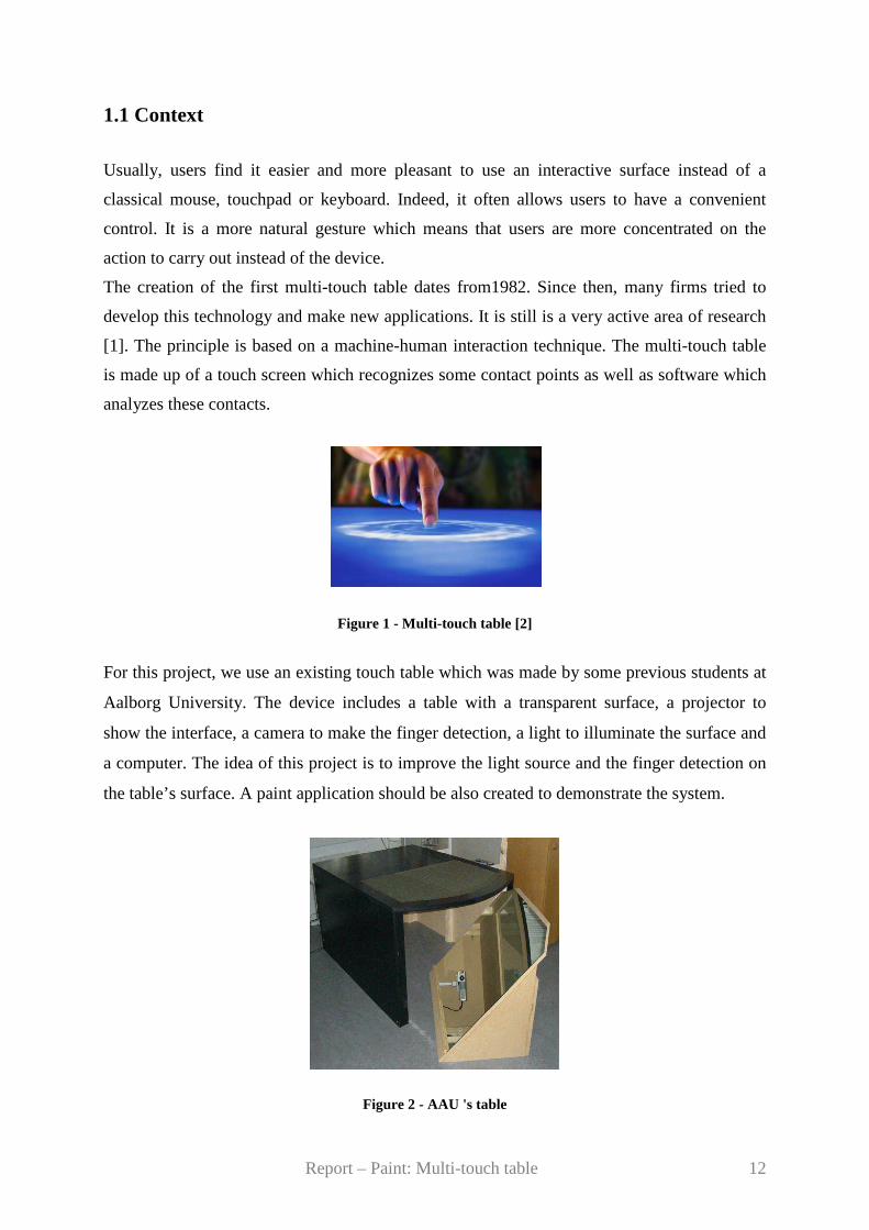
The creation of the first multi-touch table dates from1982. Since then, many firms tried to
develop this technology and make new applications. It is still is a very active area of research
[1]. The principle is based on a machine-human interaction technique. The multi-touch table
is made up of a touch screen which recognizes some contact points as well as software which
analyzes these contacts.
Figure 1 - Multi-touch table [2]
For this project, we use an existing touch table which was made by some previous students at
Aalborg University. The device includes a table with a transparent surface, a projector to
show the interface, a camera to make the finger detection, a light to illuminate the surface and
a computer. The idea of this project is to improve the light source and the finger detection on
the table’s surface. A paint application should be also created to demonstrate the system.
Figure 2 - AAU 's table

Report – Paint: Multi-touch table 13
The use of whiteboards is very spread in the working world and especially in the meetings.
Indeed, it allows someone to give better explanations by using drawings and diagrams. It is
very easy and fast to use. But one of its drawbacks is that it is not possible to do modifications
on drawing and save them. That is why a digital version is really interesting.
1.2 Objectives
The aims are:
� To improve the general and physical structure of the tabletop display. This point
includes the lighting of the table and the position of the elements below the table. The
different issues and solutions will be explained in the next part.
� To improve the software. The purpose is to have a faster video processing engine than
the existing one. It has to be more compatible with all elements of the table (for example with
the camera).
� To make a drawing application with a user-friendly interface. The user will be able to
draw and save his work. This application will be inspired by the Microsoft Paint.
To carry through this project and to achieve these objectives, it is necessary to study the
previous project, to analyse the context and find some solutions and ideas to build this new
project. After the set up of all the elements (table’s structure, finger detection tool, drawing
application), the system should be tested and a feedback with the conceivable improvements
should be made. All this steps are described in this report.

Report – Paint: Multi-touch table 14

Report – Paint: Multi-touch table 15
Chapter 2
Preanalysis
This chapter analyses briefly the previous projects. The elements which should be
keep and improve are deduced from this analysis. This step allows the members
of the work group to have good ideas for the creation of this project.
Report – Paint: Multi-touch table 16
2.1 Previous projects
2.1.1 Tabletop display
The previous projects used an existing tabletop display which was available at the laboratory
in Aalborg University. It is made up of several elements which are describes in the following
part.
Tabletop
The table is a wooden table. Half of the table is round and is made up of a transparent window
glass where the graphical interface is projected. This glass is covered by a plastic surface
which allows us to keep more light on the table’s surface. Therefore, we get a better image
quality.
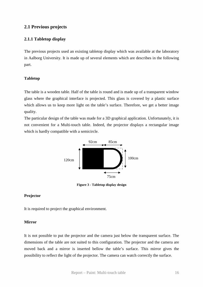
The particular design of the table was made for a 3D graphical application. Unfortunately, it is
not convenient for a Multi-touch table. Indeed, the projector displays a rectangular image
which is hardly compatible with a semicircle.
Figure 3 - Tabletop display design
Projector
It is required to project the graphical environment.
Mirror
It is not possible to put the projector and the camera just below the transparent surface. The
dimensions of the table are not suited to this configuration. The projector and the camera are
moved back and a mirror is inserted bellow the table’s surface. This mirror gives the
possibility to reflect the light of the projector. The camera can watch correctly the surface.
75cm
120cm 100cm
85cm 92cm
Report – Paint: Multi-touch table 17
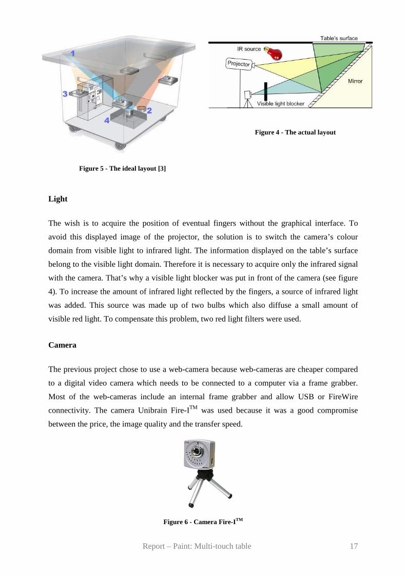
Figure 4 - The actual layout
Figure 5 - The ideal layout [3]
Light
The wish is to acquire the position of eventual fingers without the graphical interface. To
avoid this displayed image of the projector, the solution is to switch the camera’s colour
domain from visible light to infrared light. The information displayed on the table’s surface
belong to the visible light domain. Therefore it is necessary to acquire only the infrared signal
with the camera. That’s why a visible light blocker was put in front of the camera (see figure
4). To increase the amount of infrared light reflected by the fingers, a source of infrared light
was added. This source was made up of two bulbs which also diffuse a small amount of
visible red light. To compensate this problem, two red light filters were used.
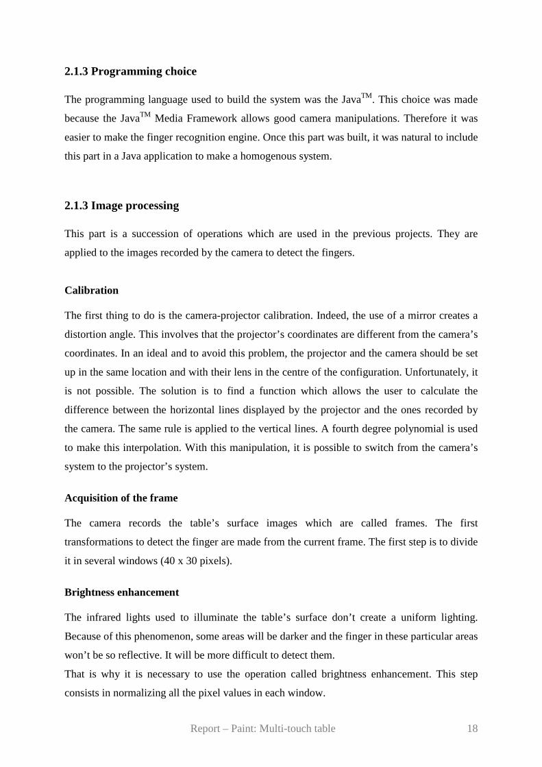
Camera
The previous project chose to use a web-camera because web-cameras are cheaper compared
to a digital video camera which needs to be connected to a computer via a frame grabber.
Most of the web-cameras include an internal frame grabber and allow USB or FireWire
connectivity. The camera Unibrain Fire-ITM was used because it was a good compromise
between the price, the image quality and the transfer speed.
Figure 6 - Camera Fire-ITM
Report – Paint: Multi-touch table 18
2.1.3 Programming choice The programming language used to build the system was the JavaTM. This choice was made
because the JavaTM Media Framework allows good camera manipulations. Therefore it was
easier to make the finger recognition engine. Once this part was built, it was natural to include
this part in a Java application to make a homogenous system.
2.1.3 Image processing This part is a succession of operations which are used in the previous projects. They are
applied to the images recorded by the camera to detect the fingers.
Calibration The first thing to do is the camera-projector calibration. Indeed, the use of a mirror creates a
distortion angle. This involves that the projector’s coordinates are different from the camera’s
coordinates. In an ideal and to avoid this problem, the projector and the camera should be set
up in the same location and with their lens in the centre of the configuration. Unfortunately, it
is not possible. The solution is to find a function which allows the user to calculate the
difference between the horizontal lines displayed by the projector and the ones recorded by
the camera. The same rule is applied to the vertical lines. A fourth degree polynomial is used
to make this interpolation. With this manipulation, it is possible to switch from the camera’s
system to the projector’s system.
Acquisition of the frame The camera records the table’s surface images which are called frames. The first
transformations to detect the finger are made from the current frame. The first step is to divide
it in several windows (40 x 30 pixels).
Brightness enhancement The infrared lights used to illuminate the table’s surface don’t create a uniform lighting.
Because of this phenomenon, some areas will be darker and the finger in these particular areas
won’t be so reflective. It will be more difficult to detect them.
That is why it is necessary to use the operation called brightness enhancement. This step
consists in normalizing all the pixel values in each window.

Report – Paint: Multi-touch table 19
Each pixel value will be multiplied by a factor which transforms the highest pixel’s value in
255. After this, all the probable fingers will appear brighter.To not normalize the dark areas
which don’t contain a finger, a threshold εBr_E is introduced. Indeed, for the dark area without
finger, the factor is very high. Therefore, this threshold allows us to keep only the windows
where the factor is less than this threshold and transform the others in black windows.
Subtraction The aim of the subtraction is to make the difference between the current image and the
reference image. This procedure allows the user to detect the foreground objects. This
subtraction is only applied in the previous windows that we keep.
Binarization Another step is the binarization. It is an operation which transforms the image in a black and
white image. To do so, a threshold εB is used. All the pixel’s values below the value εB are
changed in black, the ones above, are put in white.
Holes’ removal After binarization, the fingers look like discontinuous spots. Thus, this step consists in
creating continuous areas.
Spots creation This stage is the last one to get the spots which maybe correspond to the fingers. The purpose
is to look all the close neighbours (8 pixels) of a pixel. If they are white, they are added to the
previous spot.
Discard Size To be sure that all the spots that we observe are a finger, it is necessary to check a last feature:
the size. Indeed, if the size of a spot is too big or too small, it might be noise and it is
removed.
Report – Paint: Multi-touch table 20
2.1.4 Applications Music application The idea of this project is to use and navigate through a music library where the songs are
categorized not with a type but with colours.
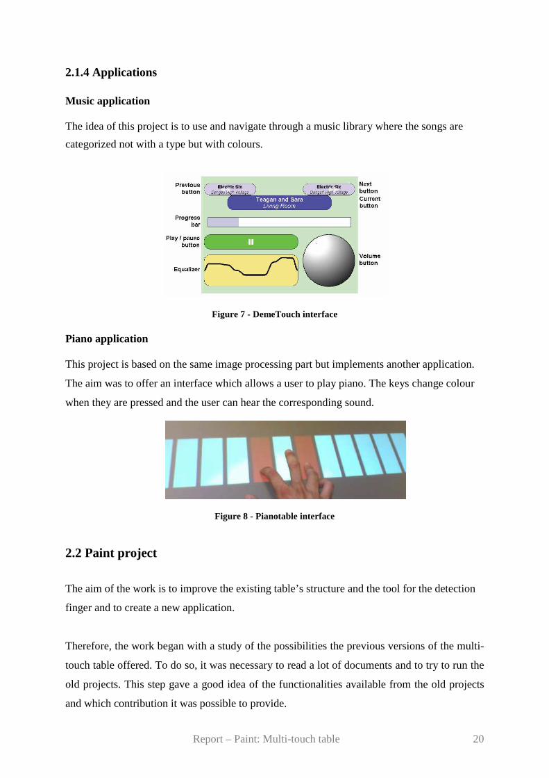
Figure 7 - DemeTouch interface Piano application This project is based on the same image processing part but implements another application.
The aim was to offer an interface which allows a user to play piano. The keys change colour
when they are pressed and the user can hear the corresponding sound.
Figure 8 - Pianotable interface
2.2 Paint project
The aim of the work is to improve the existing table’s structure and the tool for the detection
finger and to create a new application.
Therefore, the work began with a study of the possibilities the previous versions of the multi-
touch table offered. To do so, it was necessary to read a lot of documents and to try to run the
old projects. This step gave a good idea of the functionalities available from the old projects
and which contribution it was possible to provide.
Report – Paint: Multi-touch table 21
Besides, a reflection about computer languages was required. The choice of these languages,
improvements and innovations will be explained in the followings part.
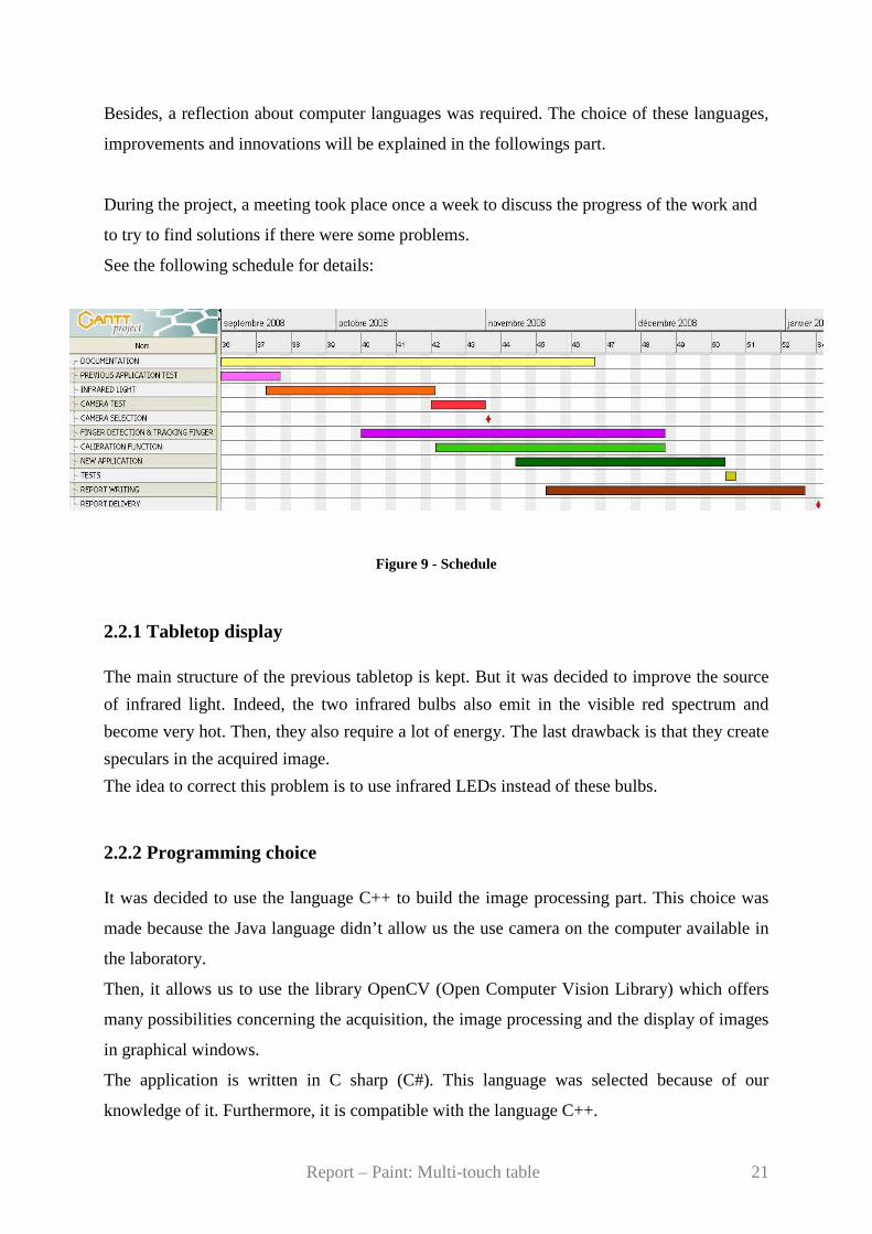
During the project, a meeting took place once a week to discuss the progress of the work and
to try to find solutions if there were some problems.
See the following schedule for details:
Figure 9 - Schedule
2.2.1 Tabletop display The main structure of the previous tabletop is kept. But it was decided to improve the source
of infrared light. Indeed, the two infrared bulbs also emit in the visible red spectrum and
become very hot. Then, they also require a lot of energy. The last drawback is that they create
speculars in the acquired image.
The idea to correct this problem is to use infrared LEDs instead of these bulbs.
2.2.2 Programming choice It was decided to use the language C++ to build the image processing part. This choice was
made because the Java language didn’t allow us the use camera on the computer available in
the laboratory.
Then, it allows us to use the library OpenCV (Open Computer Vision Library) which offers
many possibilities concerning the acquisition, the image processing and the display of images
in graphical windows.
The application is written in C sharp (C#). This language was selected because of our
knowledge of it. Furthermore, it is compatible with the language C++.
Report – Paint: Multi-touch table 22
2.2.3 Image processing The image processing part of the previous projects was analysed and one of the aim of this
project is to improve it. Of course some steps will be kept as the acquisition of the reference
image, the subtraction… but some of them will be removed and some other added in order to
make the system better. Then, the order in which the operations took place will probably not
be followed. For example, it is more common, to begin which the subtraction and to work on
the subtracted image instead of the current image.
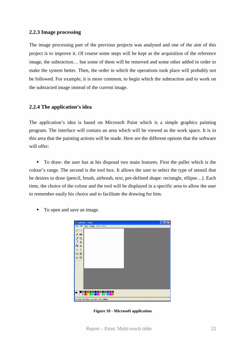
2.2.4 The application’s idea
The application’s idea is based on Microsoft Paint which is a simple graphics painting
program. The interface will contain an area which will be viewed as the work space. It is in
this area that the painting actions will be made. Here are the different options that the software
will offer:
� To draw: the user has at his disposal two main features. First the pallet which is the
colour’s range. The second is the tool box. It allows the user to select the type of utensil that
he desires to draw (pencil, brush, airbrush, text, pre-defined shape: rectangle, ellipse…). Each
time, the choice of the colour and the tool will be displayed in a specific area to allow the user
to remember easily his choice and to facilitate the drawing for him.
� To open and save an image.
Figure 10 - Microsoft application
Report – Paint: Multi-touch table 23
Chapter 3
Analysis
This chapter analyses the problems, the different possibilities and chosen
solutions for the development of this project. This part concerns essentially the
configuration of the table and the image processing tool.
Report – Paint: Multi-touch table 24
3.1 Infrared light
A camera which is able to see in the visible spectrum, will perceive the fingers but also the
projected image on the table’s surface. The aim is to detect finger. Therefore, it is easier if it is
possible to avoid the view of the projected image. Indeed, it is simpler to work on the image
with only fingers.
It turns out that the projector emits light only in the visible. That is why the solution is to
choose a camera which is sensible to IR (InfraRed) light. In the previous project, it was
realized that the ambient IR light was “not sufficient to provide enough contrast for any kind
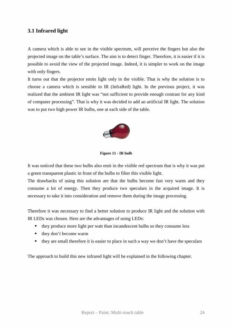
of computer processing”. That is why it was decided to add an artificial IR light. The solution
was to put two high power IR bulbs, one at each side of the table.
Figure 11 - IR bulb
It was noticed that these two bulbs also emit in the visible red spectrum that is why it was put
a green transparent plastic in front of the bulbs to filter this visible light.
The drawbacks of using this solution are that the bulbs become fast very warm and they
consume a lot of energy. Then they produce two speculars in the acquired image. It is
necessary to take it into consideration and remove them during the image processing.
Therefore it was necessary to find a better solution to produce IR light and the solution with
IR LEDs was chosen. Here are the advantages of using LEDs:
� they produce more light per watt than incandescent bulbs so they consume less
� they don’t become warm
� they are small therefore it is easier to place in such a way we don’t have the speculars
The approach to build this new infrared light will be explained in the following chapter.
Report – Paint: Multi-touch table 25
3.2 Projector
As said in the last part, the speculars due to the infrared light can be avoided. But the one due
to the projector remains. To attenuate or to remove this specular, it could be necessary to put
another surface on the lower part of the glass window. The idea is to turn over the glass
window which already owns such a surface on is top.
3.3 Camera
As said in chapter 2, the camera used in previous projects is the web-camera Unibrain Fire-
ITM. Unfortunately, there was a problem of incompatibility between the Java language and the
camera on the available computer.
Some tests with other cameras were made. The first test was made with the Philips
PCVC840K/20 camera. But it was too slow to follow the movement of the fingers. For the
second test, the Philips SPC-225NC camera was used. This web-camera contained an IR
filter, which was removed from the lens of the web-camera. This camera was fast enough but
the resolution of the camera was low which involves that the position of the fingers was
interpolated.
Finally, the solution was to keep the Unibrain Fire-ITM camera and to use the language C++
instead of the JavaTM as explained in the part 2.2.2.
3.4 Image processing
A good processing engine should be fast. It is necessary to have a good latency-free response
from the system to the user command. Indeed, the user needs to see what he is drawing in real
time in order to work continuously. This feature depends on the type of the camera but also
on the image processing part. The following paragraphs will explain the important steps to
know for the image processing engine of this project.
Report – Paint: Multi-touch table 26
3.4.1 Basic notions in image processing
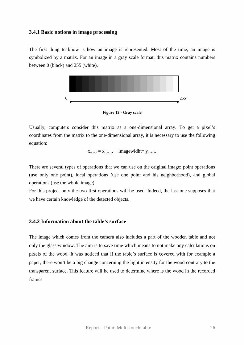
The first thing to know is how an image is represented. Most of the time, an image is
symbolized by a matrix. For an image in a gray scale format, this matrix contains numbers
between 0 (black) and 255 (white).
Figure 12 - Gray scale
Usually, computers consider this matrix as a one-dimensional array. To get a pixel’s
coordinates from the matrix to the one-dimensional array, it is necessary to use the following
equation:
xarray = xmatrix + imagewidht* ymatrix
There are several types of operations that we can use on the original image: point operations
(use only one point), local operations (use one point and his neighborhood), and global
operations (use the whole image).
For this project only the two first operations will be used. Indeed, the last one supposes that
we have certain knowledge of the detected objects.
3.4.2 Information about the table’s surface
The image which comes from the camera also includes a part of the wooden table and not
only the glass window. The aim is to save time which means to not make any calculations on
pixels of the wood. It was noticed that if the table’s surface is covered with for example a
paper, there won’t be a big change concerning the light intensity for the wood contrary to the
transparent surface. This feature will be used to determine where is the wood in the recorded
frames.
255 0
Report – Paint: Multi-touch table 27
3.4.3 Subtraction
The subtraction is necessary to detect the foreground objects. This means to make the
difference between the current image and the reference image. This procedure is a pixel-by-
pixel operation. Let ( , )CI x y the current image, ( , )RI x y the reference image and ( , )FI x y the
final image. The subtraction operation is given by the following equation:
( , ) ( , ) ( , )F C RI x y I x y I x y= −
The negative pixel values which result from this operation are deleted because for most of
them, it is noise.
The result of this subtraction is that all the zones which don’t contain fingers will have the
pixels set to 0. Unfortunately, the environment (illumination) is changing that is why the
zones without finger of the current are never perfectly equal to the reference image. This
feature introduces some noise in the final image.
To get a satisfying result of the subtraction, it is necessary to have a good reference image.
For this project, this image, which is called background, is the one which is without fingers.
The first couple of frames are not advisable to create the reference image. Indeed, the camera
needs few seconds to acquire the right image (i.e. with the good lighting…). To know which
frames we can use we will calculate how bright the image is. We keep the frames which are
within the range plus or minus 5 percent of a pre defined threshold. As said before, this
background is not usable all the time because the environment changes.
To get a good background, in order to remove the noise, it needs to be updated. Most of the
time fingers appear on the frame. So, it is necessary to remove them from the image. First, the
method consists in determining where the fingers are and then in defining the Region Of
Interest (ROI) which contains the fingers. Then, the Goris-Watson algorithm is used to make
the interpolation of the background. This method is applied in medical image processing (it is
involved in the measurement of the myocardial perfusion). With this algorithm we try to
figure out what can be below the object. To do so, an interpolation of the pixel values behind
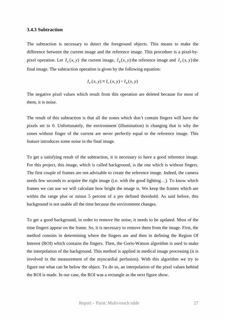
the ROI is made. In our case, the ROI was a rectangle as the next figure show.
Report – Paint: Multi-touch table 28
Figure 13 - ROI
The formula to get the value of the pixel P is:
( )( )
a b c d
a b c d
aw bw cw dwP
w w w w
+ + +=
+ + +
Where:
( )a 2 1w = y / y + 1
( )b 2 1w = x / x + 1
( )c 1 2w = y / y + 1
( )d 1 2w = x / x + 1
And a,b,c,d mean the pixel values on the ROI’s border.
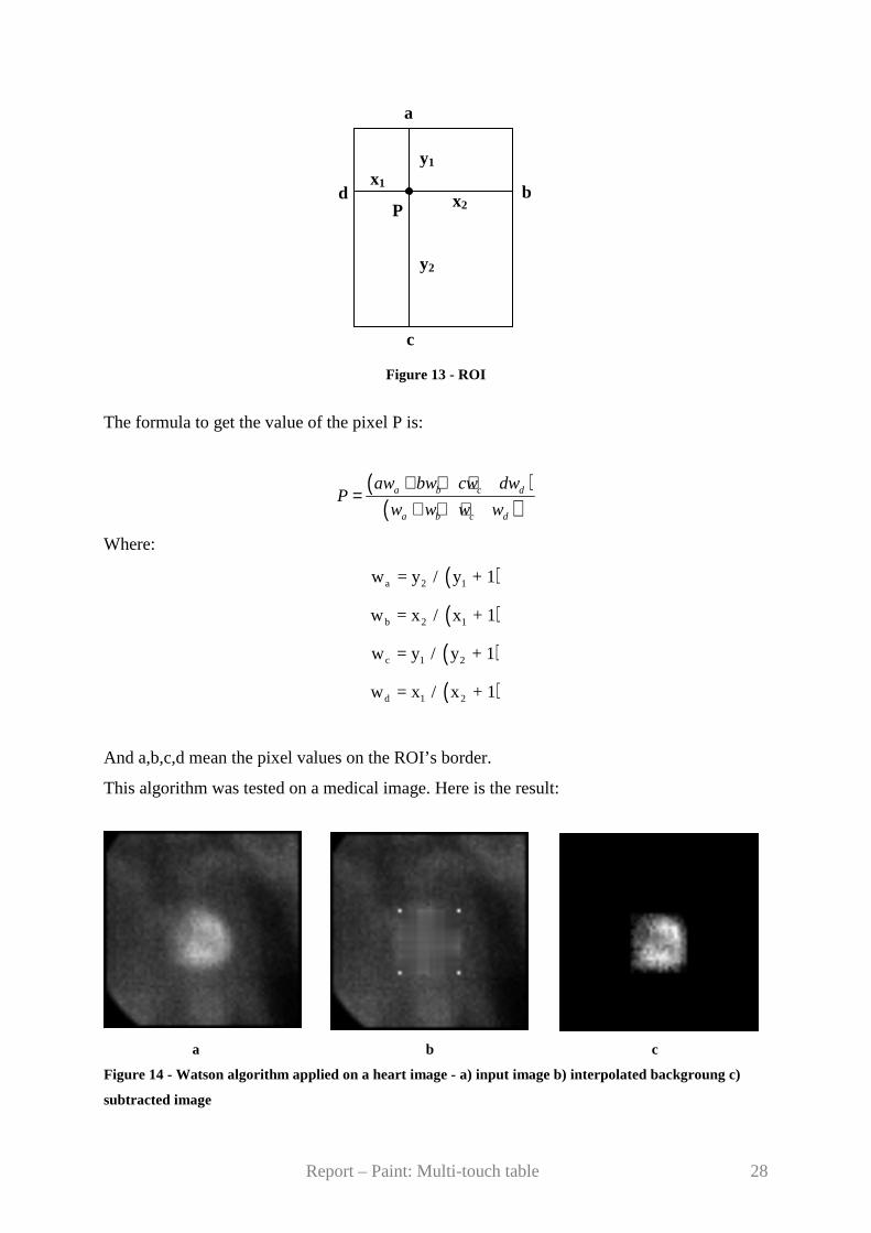
This algorithm was tested on a medical image. Here is the result:
a b c
Figure 14 - Watson algorithm applied on a heart image - a) input image b) interpolated backgroung c)
subtracted image
d b
y2
x2
y1 x1
c
a
P
Report – Paint: Multi-touch table 29
This algorithm gives a good result with the previous image. Unfortunately, there are some
problems in using it with the tabletop display. The first one is that it requires a lot of computer
power. Then, the glass window is not a rectangle, it has a circular part. Sometimes, a corner of
the ROI is on wood of the table. The wood is as bright as a finger so it is considered as such.
This involves some mistakes in the calculation. Because of the shape of the table, this solution
is not optimum.
Another idea is to use only the frames during which the user doesn’t touch the table’s surface.
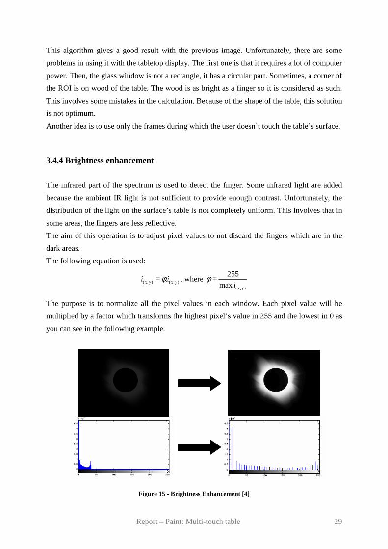
3.4.4 Brightness enhancement
The infrared part of the spectrum is used to detect the finger. Some infrared light are added
because the ambient IR light is not sufficient to provide enough contrast. Unfortunately, the
distribution of the light on the surface’s table is not completely uniform. This involves that in
some areas, the fingers are less reflective.
The aim of this operation is to adjust pixel values to not discard the fingers which are in the
dark areas.
The following equation is used:
( , ) ( , ).x y x yi iφ= , where ( , )
255
max x yiφ =
The purpose is to normalize all the pixel values in each window. Each pixel value will be
multiplied by a factor which transforms the highest pixel’s value in 255 and the lowest in 0 as
you can see in the following example.
Figure 15 - Brightness Enhancement [4]
Report – Paint: Multi-touch table 30
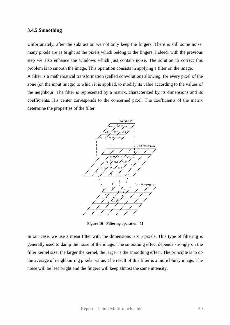
3.4.5 Smoothing
Unfortunately, after the subtraction we not only keep the fingers. There is still some noise:
many pixels are as bright as the pixels which belong to the fingers. Indeed, with the previous
step we also enhance the windows which just contain noise. The solution to correct this
problem is to smooth the image. This operation consists in applying a filter on the image.
A filter is a mathematical transformation (called convolution) allowing, for every pixel of the
zone (on the input image) to which it is applied, to modify its value according to the values of
the neighbour. The filter is represented by a matrix, characterized by its dimensions and its
coefficients. His center corresponds to the concerned pixel. The coefficients of the matrix
determine the properties of the filter.
Figure 16 - Filtering operation [5]
In our case, we use a mean filter with the dimensions 5 x 5 pixels. This type of filtering is
generally used to damp the noise of the image. The smoothing effect depends strongly on the
filter kernel size: the larger the kernel, the larger is the smoothing effect. The principle is to do
the average of neighbouring pixels’ value. The result of this filter is a more blurry image. The
noise will be less bright and the fingers will keep almost the same intensity.

Report – Paint: Multi-touch table 31
Here is an example of the result that it is possible to get with a mean filter:
Figure 17 - Smoothing [6]
3.4.6 Binarization
Binarization is an operation which transforms the pixel of an image in two types of pixels:
black pixel (value 0) and white pixel (value 255).
Usually, a threshold εB is introduced. All the pixels which own a value below the threshold
are set in black, while those have a value above the threshold are set in white. Here is the
equation which represents this binarization:
255 if ( , )x y Bi ε>
0 otherwise
With this operation, we will remove the major part of the noise. On the following page is an
example of binarization:
Figure 18 - Binarization [7]
( , )x yi =
Report – Paint: Multi-touch table 32
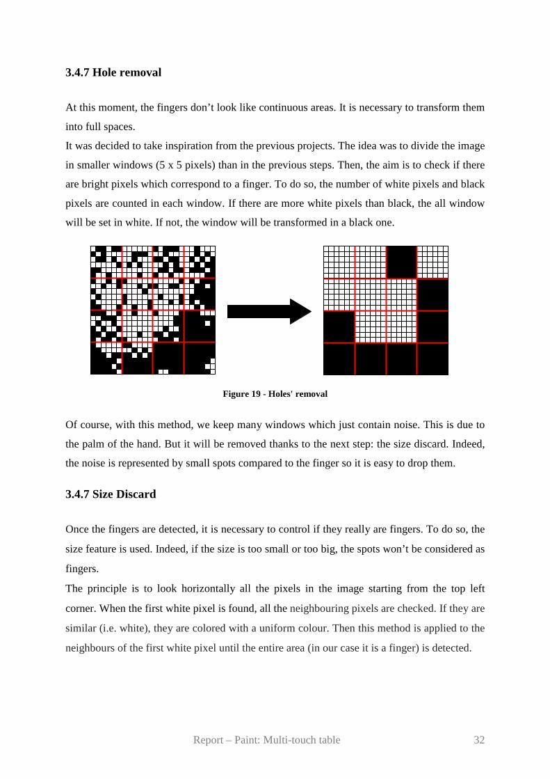
3.4.7 Hole removal
At this moment, the fingers don’t look like continuous areas. It is necessary to transform them
into full spaces.
It was decided to take inspiration from the previous projects. The idea was to divide the image
in smaller windows (5 x 5 pixels) than in the previous steps. Then, the aim is to check if there
are bright pixels which correspond to a finger. To do so, the number of white pixels and black
pixels are counted in each window. If there are more white pixels than black, the all window
will be set in white. If not, the window will be transformed in a black one.
Figure 19 - Holes' removal
Of course, with this method, we keep many windows which just contain noise. This is due to
the palm of the hand. But it will be removed thanks to the next step: the size discard. Indeed,
the noise is represented by small spots compared to the finger so it is easy to drop them.
3.4.7 Size Discard
Once the fingers are detected, it is necessary to control if they really are fingers. To do so, the
size feature is used. Indeed, if the size is too small or too big, the spots won’t be considered as
fingers.
The principle is to look horizontally all the pixels in the image starting from the top left
corner. When the first white pixel is found, all the neighbouring pixels are checked. If they are
similar (i.e. white), they are colored with a uniform colour. Then this method is applied to the
neighbours of the first white pixel until the entire area (in our case it is a finger) is detected.
Report – Paint: Multi-touch table 33
After this, we start again to check horizontally the pixels from the pixel on the right side of
the first found white pixel. If the next white pixels belong to the element detected before, their
neighbours are not checked.
Each time an element is detected, the number of pixels which constitute this spot are counted.
If this number is spread between 15 and 100 pixels, it is considered as a finger and will be
kept. Otherwise, it is estimated as noise and will be removed from the image.
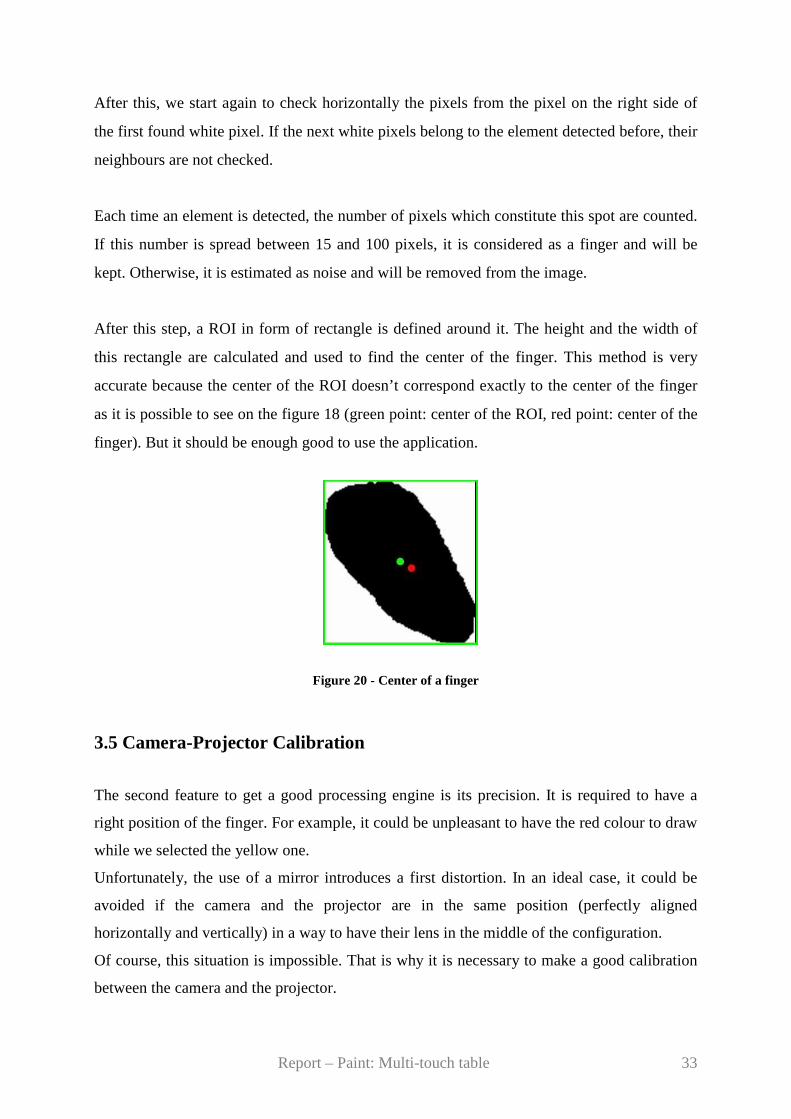
After this step, a ROI in form of rectangle is defined around it. The height and the width of
this rectangle are calculated and used to find the center of the finger. This method is very
accurate because the center of the ROI doesn’t correspond exactly to the center of the finger
as it is possible to see on the figure 18 (green point: center of the ROI, red point: center of the
finger). But it should be enough good to use the application.
Figure 20 - Center of a finger
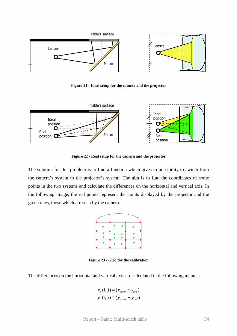
3.5 Camera-Projector Calibration
The second feature to get a good processing engine is its precision. It is required to have a
right position of the finger. For example, it could be unpleasant to have the red colour to draw
while we selected the yellow one.
Unfortunately, the use of a mirror introduces a first distortion. In an ideal case, it could be
avoided if the camera and the projector are in the same position (perfectly aligned
horizontally and vertically) in a way to have their lens in the middle of the configuration.
Of course, this situation is impossible. That is why it is necessary to make a good calibration
between the camera and the projector.
Report – Paint: Multi-touch table 34
Ideal position
Real position
Lenses
Table’s surface
Mirror
Ideal
position
Table’s surface
Mirror Real
position
Figure 21 - Ideal setup for the camera and the projector
Figure 22 - Real setup for the camera and the projector
The solution for this problem is to find a function which gives to possibility to switch from
the camera’s system to the projector’s system. The aim is to find the coordinates of some
points in the two systems and calculate the differences on the horizontal and vertical axis. In
the following image, the red points represent the points displayed by the projector and the
green ones, those which are seen by the camera.
Figure 23 - Grid for the calibration
The differences on the horizontal and vertical axis are calculated in the following manner:
( , ) ( )d green redx i j x x= −
( , ) ( )d green redy i j y y= −
Lenses
Report – Paint: Multi-touch table 35
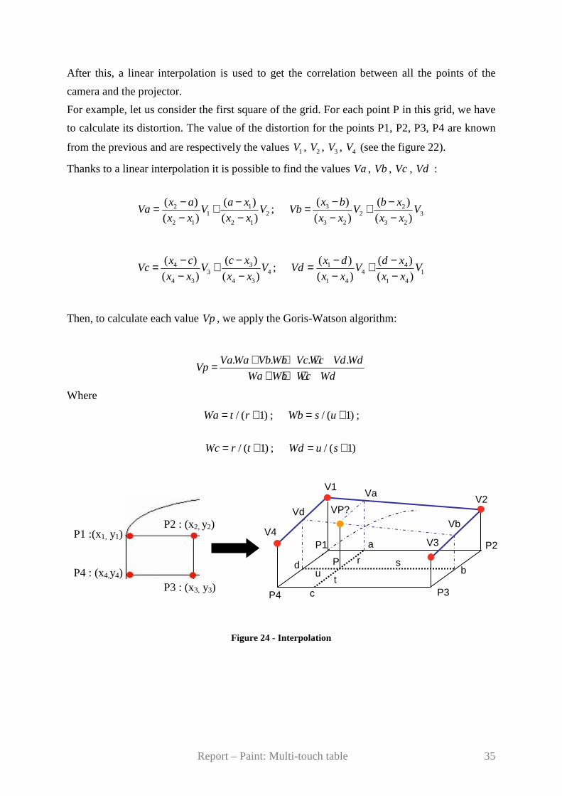
After this, a linear interpolation is used to get the correlation between all the points of the
camera and the projector.
For example, let us consider the first square of the grid. For each point P in this grid, we have
to calculate its distortion. The value of the distortion for the points P1, P2, P3, P4 are known
from the previous and are respectively the values 1V , 2V , 3V , 4V (see the figure 22).
Thanks to a linear interpolation it is possible to find the values Va , Vb , Vc , Vd :
2 11 2
2 1 2 1
( ) ( )
( ) ( )
x a a xVa V V
x x x x
− −= +− −
; 3 22 3
3 2 3 2
( ) ( )
( ) ( )
x b b xVb V V
x x x x
− −= +− −
343 4
4 3 4 3
( )( )
( ) ( )
c xx cVc V V
x x x x
−−= +− −
; 1 44 1
1 4 1 4
( ) ( )
( ) ( )
x d d xVd V V
x x x x
− −= +− −
Then, to calculate each value Vp , we apply the Goris-Watson algorithm:
. . . .VaWa VbWb VcWc Vd WdVp
Wa Wb Wc Wd
+ + +=+ + +
Where
/ ( 1)Wa t r= + ; / ( 1)Wb s u= + ;
/ ( 1)Wc r t= + ; / ( 1)Wd u s= +
Figure 24 - Interpolation
P1 :(x1, y1) P2 : (x2, y2)
P4 : (x4,y4) P3 : (x3, y3)
P
P1 P2
P3 P4
V1 V2
V3 V4
VP?
a
b
c
d
Vd Vb
Va
r s
t u

Report – Paint: Multi-touch table 36
The second source of distortion is a radial distortion due to the lens of the camera. As it
possible to see on the following images, the grid that is displayed on the table’s surface thanks
to the projector (left figure) won’t be perceived in the same way by the camera (right image).
This difference becomes more significant as the focal length of the lens decreases [8].
Figure 25 - Radial distortion This distortion could be also corrected. Here is the formula to overcome this problem:
^
( )( )c cx x L r x x= + − ^
( )( )c cy y L r y y= + −
Where ( , )x y are the measured coordinates, ^ ^
( , )x y the corrected coordinates, ( , )c cx y the
centre of radial distortion, 2 2 2( ) ( )c cr x x y y= − + − 2 2 2( ) ( )c cr x x y y= − + − and ( )L r a
distortion factor.
3.6 Tracking finger
It is necessary to track the finger in the video stream. Indeed, it is essential to know the
distance covered by the finger to draw well the corresponding figure. For example, if the user
wants to plot a line and moves his finger from 10 pixels, the result should be a line with a
length of 10 pixels.
Input image viewed by the camera
Report – Paint: Multi-touch table 37
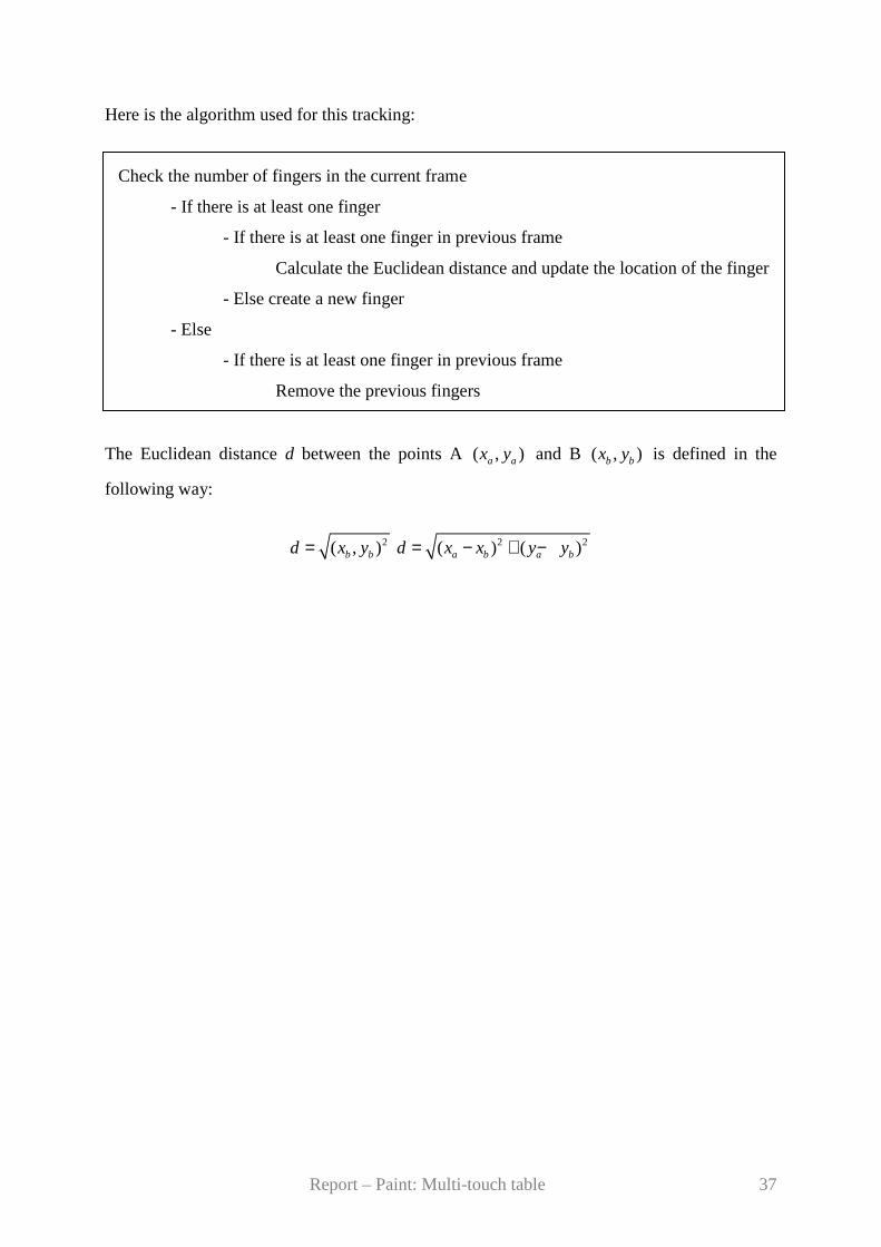
Here is the algorithm used for this tracking:
Check the number of fingers in the current frame
- If there is at least one finger
- If there is at least one finger in previous frame
Calculate the Euclidean distance and update the location of the finger
- Else create a new finger
- Else
- If there is at least one finger in previous frame
Remove the previous fingers
The Euclidean distance d between the points A ( , )a ax y and B ( , )b bx y is defined in the
following way:
2( , )b bd x y= 2 2( ) ( )a b a bd x x y y= − + −

Report – Paint: Multi-touch table 38
Report – Paint: Multi-touch table 39
Chapter 4
Design
This chapter presents in depth the chosen solutions and their roles. It also
describes how they are set up and what are the advantages and the results.
Report – Paint: Multi-touch table 40
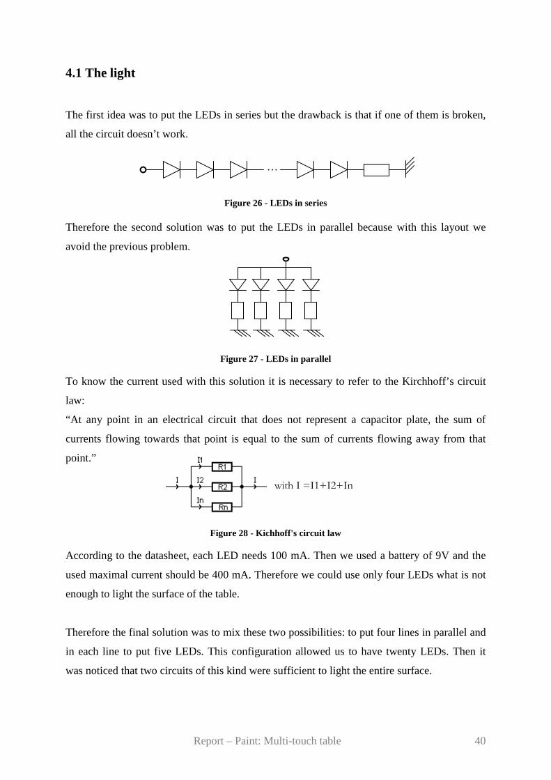
4.1 The light
The first idea was to put the LEDs in series but the drawback is that if one of them is broken,
all the circuit doesn’t work.
Figure 26 - LEDs in series
Therefore the second solution was to put the LEDs in parallel because with this layout we
avoid the previous problem.
Figure 27 - LEDs in parallel To know the current used with this solution it is necessary to refer to the Kirchhoff’s circuit
law:
“At any point in an electrical circuit that does not represent a capacitor plate, the sum of
currents flowing towards that point is equal to the sum of currents flowing away from that
point.”
Figure 28 - Kichhoff's circuit law According to the datasheet, each LED needs 100 mA. Then we used a battery of 9V and the
used maximal current should be 400 mA. Therefore we could use only four LEDs what is not
enough to light the surface of the table.
Therefore the final solution was to mix these two possibilities: to put four lines in parallel and
in each line to put five LEDs. This configuration allowed us to have twenty LEDs. Then it
was noticed that two circuits of this kind were sufficient to light the entire surface.
…
with I =I1+I2+In
Report – Paint: Multi-touch table 41
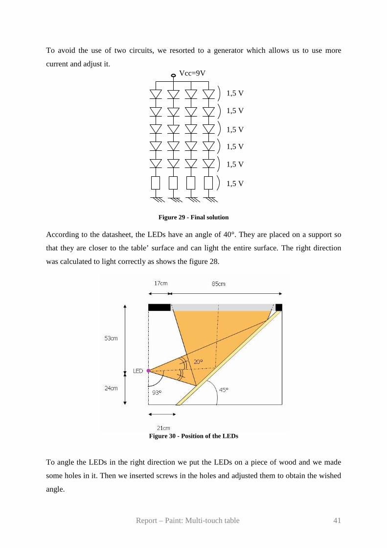
To avoid the use of two circuits, we resorted to a generator which allows us to use more
current and adjust it.
Figure 29 - Final solution According to the datasheet, the LEDs have an angle of 40°. They are placed on a support so
that they are closer to the table’ surface and can light the entire surface. The right direction
was calculated to light correctly as shows the figure 28.
Figure 30 - Position of the LEDs To angle the LEDs in the right direction we put the LEDs on a piece of wood and we made
some holes in it. Then we inserted screws in the holes and adjusted them to obtain the wished
angle.
Vcc=9V
1,5 V
1,5 V
1,5 V
1,5 V
1,5 V
1,5 V
Report – Paint: Multi-touch table 42
Support
3°
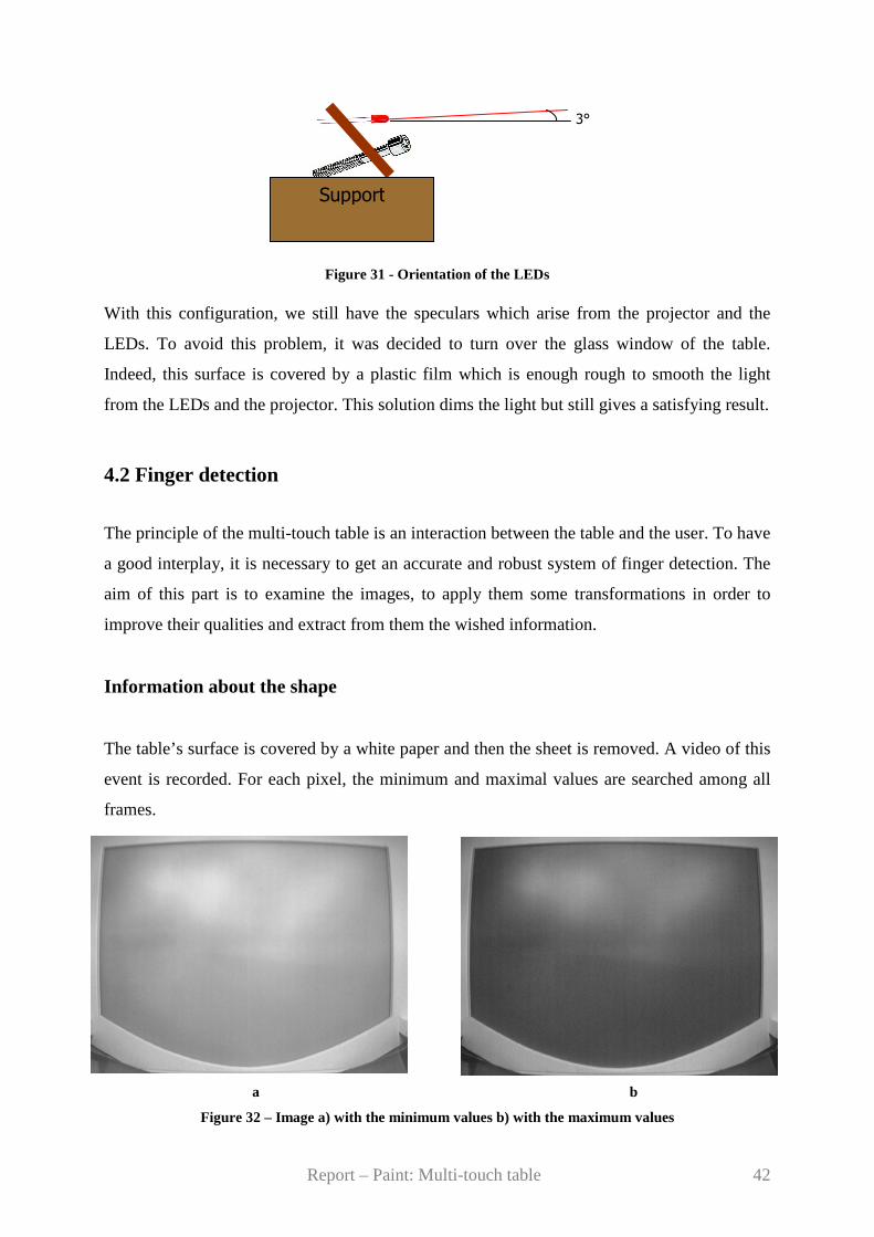
Figure 31 - Orientation of the LEDs With this configuration, we still have the speculars which arise from the projector and the
LEDs. To avoid this problem, it was decided to turn over the glass window of the table.
Indeed, this surface is covered by a plastic film which is enough rough to smooth the light
from the LEDs and the projector. This solution dims the light but still gives a satisfying result.
4.2 Finger detection
The principle of the multi-touch table is an interaction between the table and the user. To have
a good interplay, it is necessary to get an accurate and robust system of finger detection. The
aim of this part is to examine the images, to apply them some transformations in order to
improve their qualities and extract from them the wished information.
Information about the shape
The table’s surface is covered by a white paper and then the sheet is removed. A video of this
event is recorded. For each pixel, the minimum and maximal values are searched among all
frames.
a b
Figure 32 – Image a) with the minimum values b) with the maximum values
Report – Paint: Multi-touch table 43
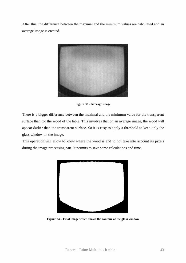
After this, the difference between the maximal and the minimum values are calculated and an
average image is created.
Figure 33 - Average image
There is a bigger difference between the maximal and the minimum value for the transparent
surface than for the wood of the table. This involves that on an average image, the wood will
appear darker than the transparent surface. So it is easy to apply a threshold to keep only the
glass window on the image.
This operation will allow to know where the wood is and to not take into account its pixels
during the image processing part. It permits to save some calculations and time.
Figure 34 – Final image which shows the contour of the glass window

Report – Paint: Multi-touch table 44
Image Acquisition
The phase of the image acquisition is essential in a system of vision. His quality will affect
simplicity and the robustness of the treatment. A system of vision contains generally:
� a light source
� a sensor (camera)
� an acquisition card (to convert the analogical information from the sensor to a
numerical information for the computer )
� a system for the treatment (computer and software)
Figure 35 - Image acquisition In our case, the first acquired image is the background. As explained in the part 3.4.2, the
camera needs the first frames to initialize itself. So it is advised to wait few seconds to acquire
the good image. Of course during this acquisition, the user is asked to not touch the table
because this image will be the reference image and will be used for the subtraction.
Figure 36 - Reference image
Object
Light source Camera
Acquisition card
Computer

Report – Paint: Multi-touch table 45
Then, what we call the current frame is recorded.
Figure 37 - Current frame with a finger
Subtraction
This stage consists in subtracting the reference image (figure 30) from the current image
(figure 29). The outcome of this operation is a black background and the fingers represented
by grayscale values.
As is it possible to see on the result (figure 31), there is a lot of noise due to the shadow of
the arm and the palm of the hand. Some parts of the noise also arise from the fact that the
environment is always changing. The background of the reference image and the current
image are not exactly the same. It follows from that some white pixels in the background.
Figure 38 - Subtracted image
Report – Paint: Multi-touch table 46
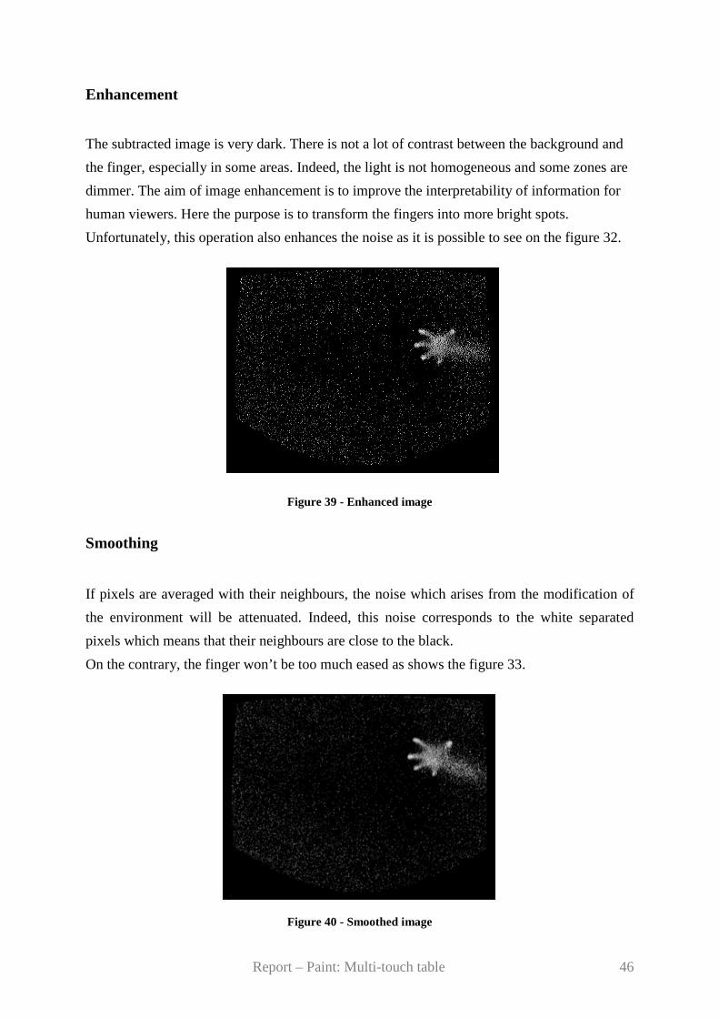
Enhancement
The subtracted image is very dark. There is not a lot of contrast between the background and
the finger, especially in some areas. Indeed, the light is not homogeneous and some zones are
dimmer. The aim of image enhancement is to improve the interpretability of information for
human viewers. Here the purpose is to transform the fingers into more bright spots.
Unfortunately, this operation also enhances the noise as it is possible to see on the figure 32.
Figure 39 - Enhanced image
Smoothing
If pixels are averaged with their neighbours, the noise which arises from the modification of
the environment will be attenuated. Indeed, this noise corresponds to the white separated
pixels which means that their neighbours are close to the black.
On the contrary, the finger won’t be too much eased as shows the figure 33.
Figure 40 - Smoothed image
Report – Paint: Multi-touch table 47
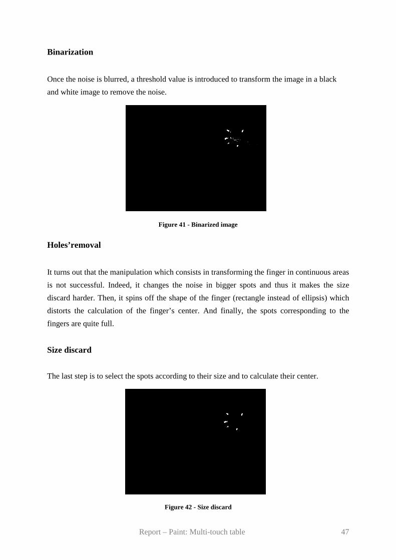
Binarization
Once the noise is blurred, a threshold value is introduced to transform the image in a black
and white image to remove the noise.
Figure 41 - Binarized image
Holes’removal
It turns out that the manipulation which consists in transforming the finger in continuous areas
is not successful. Indeed, it changes the noise in bigger spots and thus it makes the size
discard harder. Then, it spins off the shape of the finger (rectangle instead of ellipsis) which
distorts the calculation of the finger’s center. And finally, the spots corresponding to the
fingers are quite full.
Size discard
The last step is to select the spots according to their size and to calculate their center.
Figure 42 - Size discard
Report – Paint: Multi-touch table 48
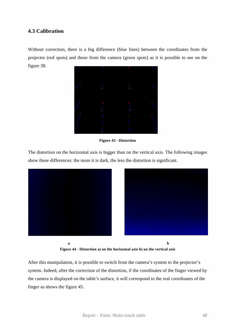
4.3 Calibration
Without correction, there is a big difference (blue lines) between the coordinates from the
projector (red spots) and those from the camera (green spots) as it is possible to see on the
figure 38.
Figure 43 - Distortion
The distortion on the horizontal axis is bigger than on the vertical axis. The following images
show these differences: the more it is dark, the less the distortion is significant.
a b Figure 44 - Distortion a) on the horizontal axis b) on the vertical axis
After this manipulation, it is possible to switch from the camera’s system to the projector’s
system. Indeed, after the correction of the distortion, if the coordinates of the finger viewed by
the camera is displayed on the table’s surface, it will correspond to the real coordinates of the
finger as shows the figure 45.
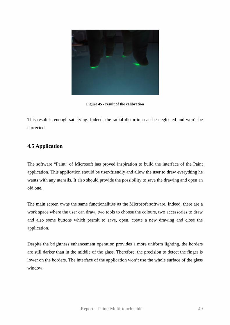
Report – Paint: Multi-touch table 49
Figure 45 - result of the calibration This result is enough satisfying. Indeed, the radial distortion can be neglected and won’t be
corrected.
4.5 Application
The software “Paint” of Microsoft has proved inspiration to build the interface of the Paint
application. This application should be user-friendly and allow the user to draw everything he
wants with any utensils. It also should provide the possibility to save the drawing and open an
old one.
The main screen owns the same functionalities as the Microsoft software. Indeed, there are a
work space where the user can draw, two tools to choose the colours, two accessories to draw
and also some buttons which permit to save, open, create a new drawing and close the
application.
Despite the brightness enhancement operation provides a more uniform lighting, the borders
are still darker than in the middle of the glass. Therefore, the precision to detect the finger is
lower on the borders. The interface of the application won’t use the whole surface of the glass
window.

Report – Paint: Multi-touch table 50
Projected interface
Figure 46 – Position of the projected interface
As said before, the interface contains four kinds of areas. The first one is the work space. This
is the white square represented on the figure 45. It is only in this particular space that the user
can draw.
Then, two tools are available on each side of the interface. On the right is the colour tool.
When the user touches the button “palette”, a pop-up window appears in which it is possible
to choose the colour. After the selection, this window disappears and the chosen colour is
displayed in the right corner of the interface. This option allows the user to remember easily
his choice.
a) b)
Figure 47 - Colour tool a) colour selection b) colour display
After the choice of the colour, it is possible to select the utensil in touching the button “tools”
on the left side.
Report – Paint: Multi-touch table 51
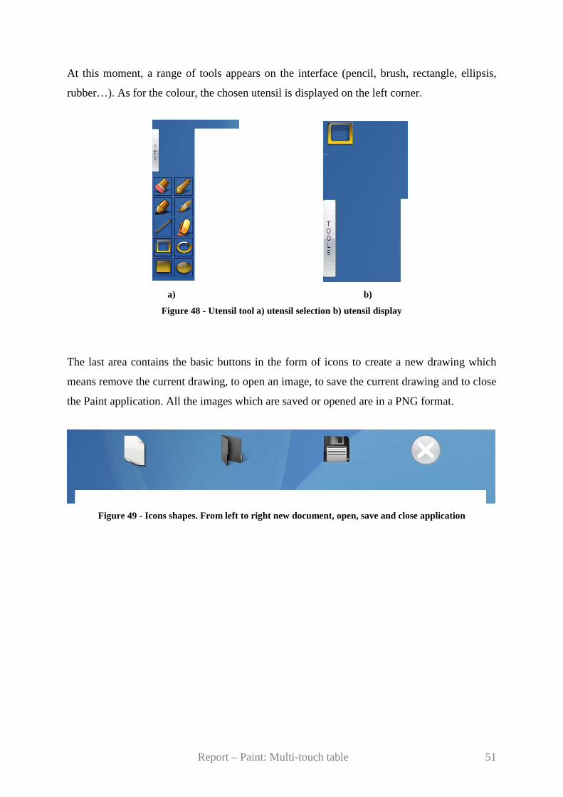
At this moment, a range of tools appears on the interface (pencil, brush, rectangle, ellipsis,
rubber…). As for the colour, the chosen utensil is displayed on the left corner.
a) b)
Figure 48 - Utensil tool a) utensil selection b) utensil display
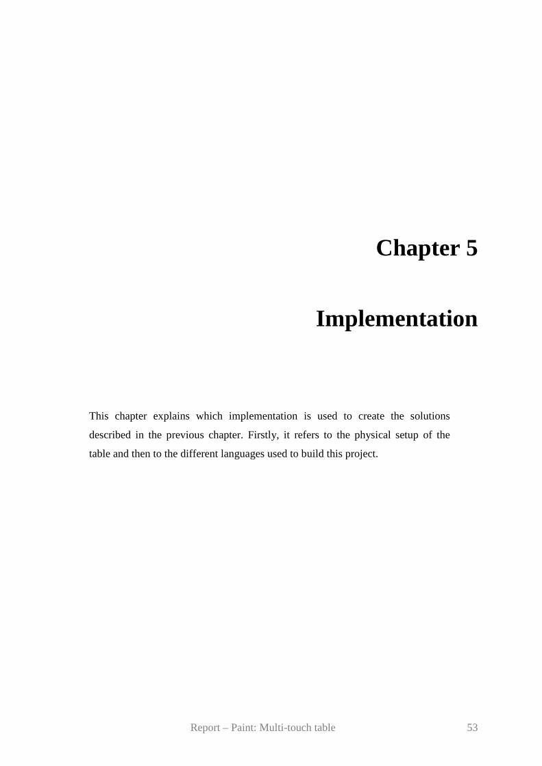
The last area contains the basic buttons in the form of icons to create a new drawing which
means remove the current drawing, to open an image, to save the current drawing and to close
the Paint application. All the images which are saved or opened are in a PNG format.
Figure 49 - Icons shapes. From left to right new document, open, save and close application

Report – Paint: Multi-touch table 52
Report – Paint: Multi-touch table 53
Chapter 5
Implementation
This chapter explains which implementation is used to create the solutions
described in the previous chapter. Firstly, it refers to the physical setup of the
table and then to the different languages used to build this project.

Report – Paint: Multi-touch table 54
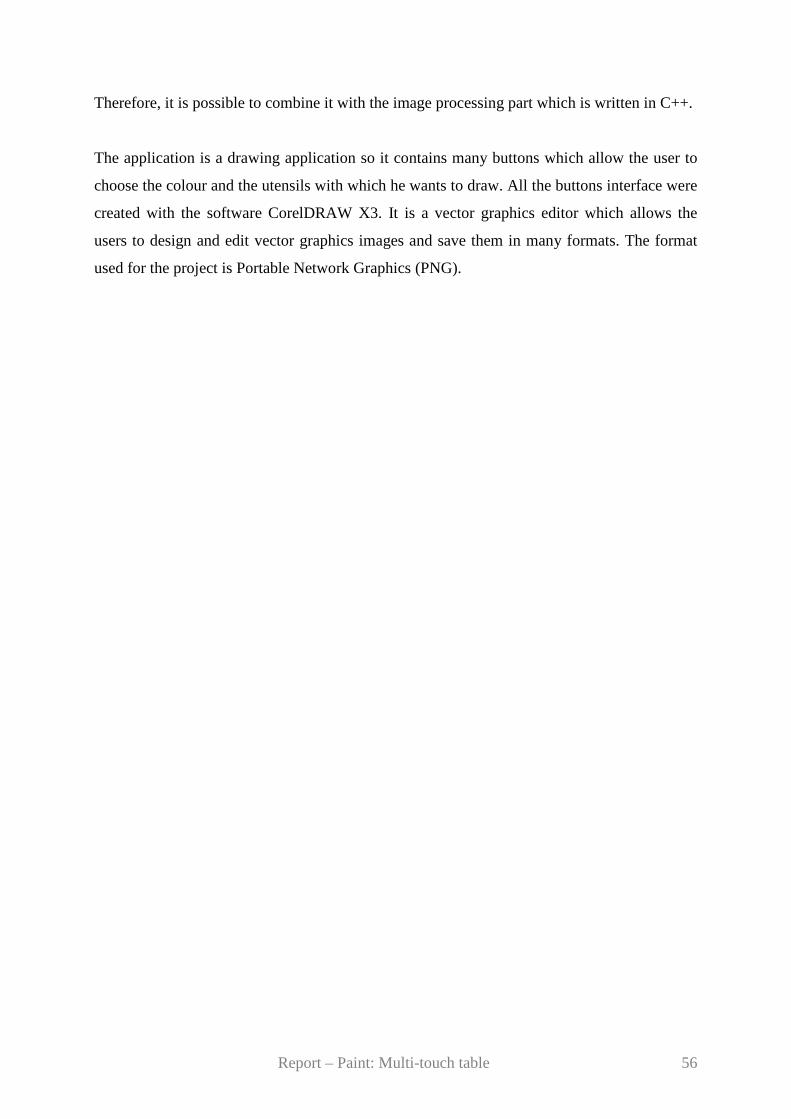
5.1 Physical setup
It is necessary to optimize the position of the elements (projector, camera, LEDs …)
compared to the table to get a good result concerning the finger detection. For example, as
explained in the part 3.5, the setting of the projector and the camera is not ideal which
produces a distortion. But it is possible to minimize this distortion if these elements are placed
in the best position.
Of course the table and the other objects can be moved. To avoid losing this optimal
configuration or spending a lot of time to find it again, all the coordinates of the elements
under the table can be measured and marked on the floor. All the details concerning the
location of the elements can be seen on the following figures.
Figure 50 - Position of the elements under the table
Report – Paint: Multi-touch table 55
Support
40cm
36cm
Figure 51 - Position of the camera related to the projector
5.2 Programming choice
As said in the part 2.2.2, the used language to build the finger detection and tracking finger
tools is C++. Contrary to the previous projects, the Java language wasn’t kept. Indeed, there
was a problem of incompatibility between this language and the use of the camera. Then, the
language C++ is faster than the Java. This allows the user to have a more efficient image
processing part and in particular a good tracking finger.
With it, it is possible to use the library OpenCV (Open Computer Vision Library). This library
offers many functions concerning the real-time image processing. Many of them are useful for
this project like the ones which permit to use the web cameras (to capture a frame from a
video sequence, to get frame information, save a video file…), to apply some filters, to
recognize elements… (See appendix A for details)
The choice of the language to make the application is C sharp (C#). The tool used to develop
this interface is Visual C# 2005. It allows the creator to put directly some buttons, menus on
the interface and the corresponding code is generated automatically. To associate actions, for
example on the buttons, with some events, it is necessary to write in the appropriate place
made by the creation of the buttons.
Then, Visual C# is integrated to the framework .NET (which permits the interoperability
between the different languages) and thus recognizes all the graphical elements of this
framework.
Report – Paint: Multi-touch table 56
Therefore, it is possible to combine it with the image processing part which is written in C++.
The application is a drawing application so it contains many buttons which allow the user to
choose the colour and the utensils with which he wants to draw. All the buttons interface were
created with the software CorelDRAW X3. It is a vector graphics editor which allows the
users to design and edit vector graphics images and save them in many formats. The format
used for the project is Portable Network Graphics (PNG).

Report – Paint: Multi-touch table 57
Chapter 6
Usability tests
Testing is a very important step in the development of a product. It allows the
builder to check the viability of his product. The aim is to ask people who don’t
make the product to use it in order to have an objective opinion and to know the
weakness and the assets. In this manner, it is possible to improve the prototype.
Report – Paint: Multi-touch table 58
The last part of this project is to test its viability. An experience with external people from the
work group is done to check if the application works correctly and demonstrates well the
efficiency of the multi-touch table technology.
To do so, five people are asked to use this Paint application. The physical setup of the
elements under the table, the calibration between the camera and the projector and the
calculation of the wood position compared to glass window are made before this test.
The finger detection is not perfect so the use of the application requires some particular
conditions. Firstly, the ambient light (from the sun and from the artificial light) should be
avoided. That is why the light is turned off and the curtains are closed. Then, if the palm of
the hand and the arm are too close from the table’s surface, the noise will appear. The user is
asked to place his hand and his arm vertically as much as possible.
Some instructions are given to the user. The execution time of each contestant is written as
well as remarks about their use of the application. Then, questions are asked to know their
opinion. (See appendix B for instructions and questionnaire)
There were no difficulties for the users to carry out the instructions. They think the functions
proposed by the tool are classic. They look like the options offered by the Microsoft Paint.
Then, the interface is nice and well design. The functionalities of the buttons are easy to
understand.
One drawback is the requirements to use the application. The position of the hand and the arm
is restrictive.
The speed and the accuracy of the application are satisfying for the users except for the choice
of the colour. The size of the finger is too big compared to the palette. It is difficult to select a
precise colour.
Report – Paint: Multi-touch table 59
Chapter 7
Improvements
After the analysis of the results and the tests, it turns out that many changes can
be brought to improve the system. This chapter explains what improvements and
development it is possible to do.
Report – Paint: Multi-touch table 60
7.1 The light
It is possible to improve the light source. Indeed, the actual light is still not homogenous.
Then, if it is more powerful, it is probable to obtain better results concerning the finger
detection.
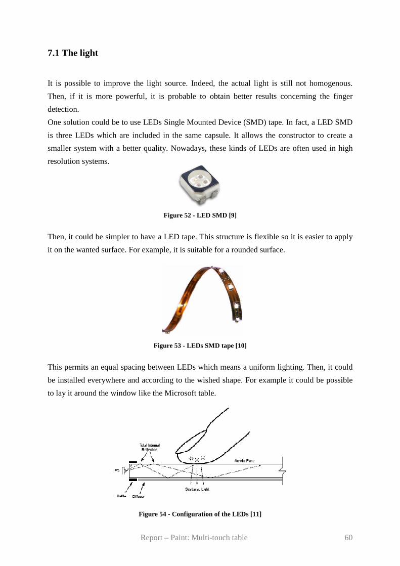
One solution could be to use LEDs Single Mounted Device (SMD) tape. In fact, a LED SMD
is three LEDs which are included in the same capsule. It allows the constructor to create a
smaller system with a better quality. Nowadays, these kinds of LEDs are often used in high
resolution systems.
Figure 52 - LED SMD [9]
Then, it could be simpler to have a LED tape. This structure is flexible so it is easier to apply
it on the wanted surface. For example, it is suitable for a rounded surface.
Figure 53 - LEDs SMD tape [10]
This permits an equal spacing between LEDs which means a uniform lighting. Then, it could
be installed everywhere and according to the wished shape. For example it could be possible
to lay it around the window like the Microsoft table.
Figure 54 - Configuration of the LEDs [11]
Report – Paint: Multi-touch table 61
7.2 The use of two camera
The use of two cameras will give the possibility to place them closer to the surface and the
mirror. The interest of this manipulation is to obtain at the end a smaller structure. Indeed, for
the moment, the table is quite bulky. Such a table (i.e. with such dimensions) could not be
commercialised.
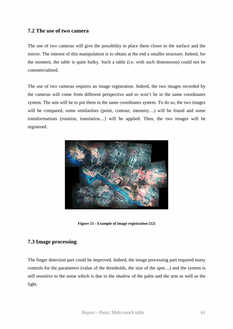
The use of two cameras requires an image registration. Indeed, the two images recorded by
the cameras will come from different perspective and so won’t be in the same coordinates
system. The aim will be to put them in the same coordinates system. To do so, the two images
will be compared, some similarities (point, contour, intensity…) will be found and some
transformations (rotation, translation…) will be applied. Then, the two images will be
registered.
Figure 55 - Example of image registration [12]
7.3 Image processing
The finger detection part could be improved. Indeed, the image processing part required many
controls for the parameters (value of the thresholds, the size of the spot…) and the system is
still sensitive to the noise which is due to the shadow of the palm and the arm as well as the
light.
Report – Paint: Multi-touch table 62
That is why for the good use, it is required to close the curtains, to turn off the light and also
to put the arm in a particular position. This imposes too many constraints to the users so the
system is not so easy and convivial to use.
Although the parameters were settled in the best way there is still a problem due to the light.
As said in the part 6.1 it is possible to improve to light source but it could be possible to
improve the finger detection tool itself.
To do so, one solution could be to use some functions proposed by the OpenCV library.
Indeed, it offers many possibilities which haven’t been explored, due to a lack of time, like
object recognition, motion analysis, camera calibration…The use of these functionalities
could allow the system to be faster and more accurate, in a nutshell, more efficient.
7.4 Paint application
The current application could be developed. The idea is to create an application like the
software Adobe Photoshop which allows a user to retouch and process some images. The
application could give the possibility to apply filters to pictures (contour detection, noise
removal, colour inversion …) but also to modify the colour’s saturation, to binarize, to get a
histogram of the image, to make image registration… Other manipulations could be added
like the stretching, the reducing, the rotation and the translation of an image.
Report – Paint: Multi-touch table 63
Chapter 8
Conclusion
This chapter gives the advantages of such a project for a group work and for
technical knowledge. It also sums up the state of the project.
Report – Paint: Multi-touch table 64
This proposed project was very interesting and gave the possibility to learn how to get
organized in a group work and to invest in a practical subject. Indeed this project has a real
industrial future because nowadays more and more firms try to develop a multi-touch table.
Some of them as Microsoft have already commercialised variants of the multi-touch table.
Aside from the human aspect, this project permitted to manage the creation and the
installation of many components, to come to grips with a new tool. It also gave the
possibilities to apply and expand the computer knowledge.
The objectives concerning this project are achieved. Indeed, the light source was improved
and the speculars removed. The finger detection as well as the tracking finger run correctly
and give a satisfying result. This allows the application to have an existence. The Paint
application is a user-friendly tool which offers a good possibility to draw and save the work.
Of course some evolutions on the tool and the application are still possible as it is possible to
see in the part 6 but the final product corresponds to the specifications and it is workable.
Report – Paint: Multi-touch table 65
References [1] W. Buxton. Multi-Touch Systems I Have Known & Love, 2007, http://www.billbuxton.
com/multitouchOverview.html
[2] http://www.pixelsumo.com/post/microsoft-surface
[3] http://www.cheaplaptops.org.uk/20070601/microsoft-surface-diagram-how-it-all-works/
[4] http://iusti.polytech.univ-mrs.fr/~vicente/supportcours/vision3-2006.pdf
[5] http://cpk.auc.dk/education/IMM/s9-08/
[6] http://note.sonots.com/SciSoftware/SpatialFilter.html
[7] http://www.iiri.com/2006bookrestorer.htm
[8] Richard Hartley and Andrew Zisserman, Multiple View Geometry in Computer Vision,
Cambrige University Press, 2003, pages 189-191
[9] http://hyled168.hisupplier.com/product-123912-full-color-smd-led.html
[10] http://www.novavisionny.com/led_strip_light.html
[11] Han, J. Y. 2005, Low-Cost Multi-Touch Sensing through Frustrated Total Internal
Reflection. In Proceedings of the 18th Annual ACM Symposium on User Interface Software
and Technology http://cs.nyu.edu/~jhan/ftirsense/
[12] http://www.geo.u-szeged.hu/STATS/2005/2005_01.html

Report – Paint: Multi-touch table 66
Report – Paint: Multi-touch table 67
Appendix
Appendix A : OpenCV functions
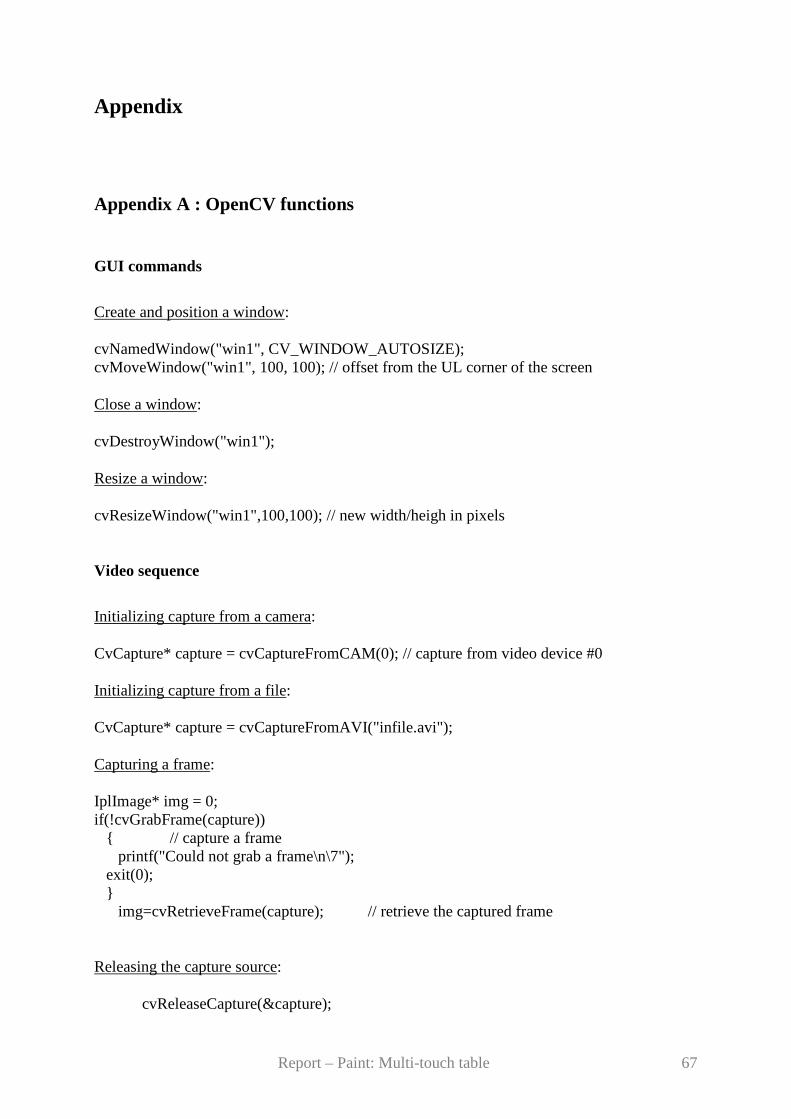
GUI commands
Create and position a window:
cvNamedWindow("win1", CV_WINDOW_AUTOSIZE); cvMoveWindow("win1", 100, 100); // offset from the UL corner of the screen
Close a window:
cvDestroyWindow("win1");
Resize a window:
cvResizeWindow("win1",100,100); // new width/heigh in pixels
Video sequence
Initializing capture from a camera:
CvCapture* capture = cvCaptureFromCAM(0); // capture from video device #0
Initializing capture from a file:
CvCapture* capture = cvCaptureFromAVI("infile.avi");
Capturing a frame:
IplImage* img = 0; if(!cvGrabFrame(capture)) { // capture a frame
printf("Could not grab a frame\n\7"); exit(0); }
img=cvRetrieveFrame(capture); // retrieve the captured frame
Releasing the capture source:
cvReleaseCapture(&capture);

Report – Paint: Multi-touch table 68
Get capture device properties:
cvQueryFrame(capture); int frameH = (int) cvGetCaptureProperty(capture, CV_CAP_PROP_FRAME_HEIGHT); int frameW = (int) cvGetCaptureProperty(capture, CV_CAP_PROP_FRAME_WIDTH); int fps = (int) cvGetCaptureProperty(capture, CV_CAP_PROP_FPS); int numFrames = (int) cvGetCaptureProperty(capture, CV_CAP_PROP_FRAME_COUNT);
Get frame information:
float posMsec = cvGetCaptureProperty(capture, CV_CAP_PROP_POS_MSEC); int posFrames = (int) cvGetCaptureProperty(capture, CV_CAP_PROP_POS_FRAMES); float posRatio = cvGetCaptureProperty(capture, CV_CAP_PROP_POS_AVI_RATIO);
Set the index of the first frame to capture:
// start capturing from a relative position of 0.9 of a video file cvSetCaptureProperty(capture, CV_CAP_PROP_POS_AVI_RATIO, (double)0.9);
Image processing
To fill the connected domain, start from seed pixel while the pixel values in this domain are not far from each other: cvFloodFill( CvArr* array, CvPoint seedPoint, double newVal, double loDiff, double upDiff, CvConnectedComp* comp, int connectivity CV_DEFAULT(4) );
To define a rectangle: cvRect(int x,int y, int width, int height);
Report – Paint: Multi-touch table 69
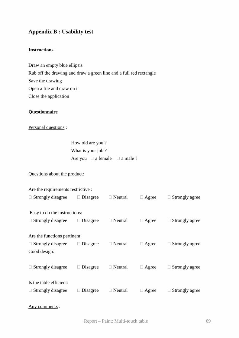
Appendix B : Usability test
Instructions
Draw an empty blue ellipsis
Rub off the drawing and draw a green line and a full red rectangle
Save the drawing
Open a file and draw on it
Close the application
Questionnaire
Personal questions :
How old are you ?
What is your job ?
Are you a female a male ?
Questions about the product:
Are the requirements restrictive :
Strongly disagree Disagree Neutral Agree Strongly agree
Easy to do the instructions:
Strongly disagree Disagree Neutral Agree Strongly agree
Are the functions pertinent:
Strongly disagree Disagree Neutral Agree Strongly agree
Good design:
Strongly disagree Disagree Neutral Agree Strongly agree
Is the table efficient:
Strongly disagree Disagree Neutral Agree Strongly agree
Any comments :