Embed Size (px)
Citation preview
Page 2 of 53 LD990607E06
Doc. No.: FSAF-65 Edition : A3 Date : January 15, 2010
TEST REPORT EN 60950-1:2006 + A11: 2009
Information technology equipment – Safety – Part 1: General requirements
ReportReference No. LD990607E06
Compiled by (+ signature) See cover sheet
Approved by (+ signature) See cover sheet
Date of issue July 01, 2010
Testing laboratoryName Bureau Veritas Consumer Products Services (H.K.) Ltd., Taoyuan
Branch
Address No. 47, 14th Lin, Chiapao Tsuen, Linko Hsiang 244, Taipei Hsien, Taiwan, R.O.C.
Testing location Bureau Veritas Consumer Products Services (H.K.) Ltd., Taoyuan Branch
Address No. 19, Hwa Ya 2nd Rd, Kueishan Taoyuan, Taiwan, R.O.C.
Client Name LOGITECH FAR EAST LTD.
Address #2 Creation Rd. 4, Science-Based Ind. Park Hsinchu Taiwan, R.O.C.
Test specificationStandard EN 60950-1:2006 + A11: 2009
Test procedure CE Marking serial in LVD
Non-standard test method N/A.
Test Report Form/blank test reportTest Report Form No. IECEN60950_1C
TRF originator. SGS Fimko Ltd
Master TRF Dated 2007-06
Test itemDescription 2.4GHz Cordless Gamepad
Trademark
1) , 2) Model and/or type reference G-R0001
Manufacturer LOGITECH FAR EAST LTD.
Rating(s) Optional, 3.0Vdc, 180mA
Page 3 of 53 LD990607E06
Doc. No.: FSAF-65 Edition : A3 Date : January 15, 2010
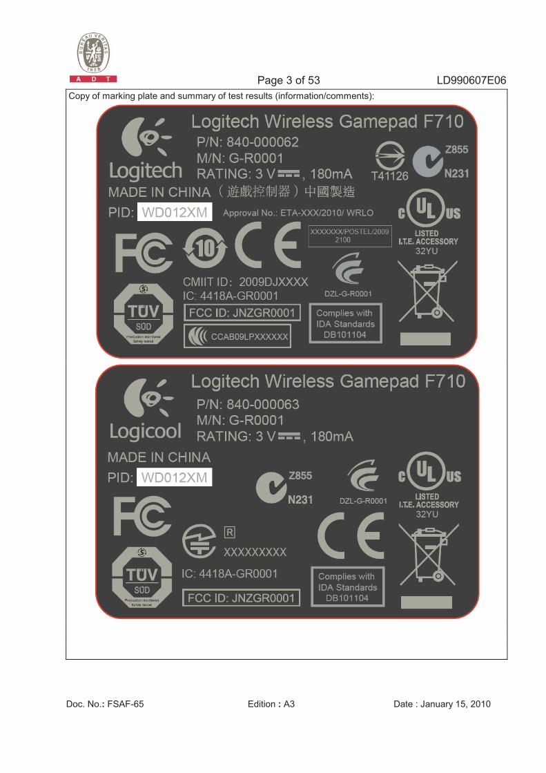
Copy of marking plate and summary of test results (information/comments):
Page 4 of 53 LD990607E06
Doc. No.: FSAF-65 Edition : A3 Date : January 15, 2010
Test item particulars
Equipment mobility [] movable [X] hand-held [] transportable [] stationary [] for building-in [] direct plug-in
Connection to the mains [] pluggable equipment [] type A [] type B [] permanent connection [] detachable power supply cord [] non-detachable power supply cord [X] not directly connected to the mains
Operating condition [X] continuous [] rated operating / resting time:
Access location [X] operator accessible [] restricted access location
Over voltage category (OVC) [] OVC I [] OVC II [] OVC III [] OVC IV [X] other: DC supply.
Mains supply tolerance (%) or absolute mains supply values
N/A
Tested for IT power systems [] Yes [X] No IT testing, phase-phase voltage (V) N/A Class of equipment [] Class I [] Class II [X] Class III
[] Not classified Considered current rating (A) See page 2. Pollution degree (PD) [] PD 1 [X] PD 2 [] PD 3 IP protection class IP20 Altitude during operation (m) < 2000m Altitude of test laboratory (m) 250m Mass of equipment (kg) 0.24 kg (without battery)
Possible test case verdicts:
- test case does not apply to the test object N/A
- test object does meet the requirement P (Pass)
- test object does not meet the requirement F (Fail)
Testing
Date of receipt of test item June 23, 2010
Date(s) of performance of tests June 23, 2010 – June 28, 2010
General remarks:
The test results presented in this report relate only to the object tested. This report shall not be reproduced, except in full, without the written approval of the Issuing testing laboratory."(See Enclosure #)" refers to additional information appended to the report. "(See appended table)" refers to a table appended to the report.
Throughout this report a point is used as the decimal separator
Page 5 of 53 LD990607E06
Doc. No.: FSAF-65 Edition : A3 Date : January 15, 2010
General product information: 1) The equipmentt is a class III 2.4GHz Cordless Gamepad. 2) The maximum ambient temperature is specified as 40oC. 3) Dimension of EUT: 154.5 by 96.8 by 67.2 mm.
Test condition: Temperature: 25oC Relative humidity: 60% Air pressure: 950 mbar
The test sample was a pre-production sample without serial number.
Page 6 of 53 LD990607E06 EN 60950-1
Clause Requirement + Test Result - Remark Verdict
Doc. No.: FSAF-65 Edition : A3 Date : January 15, 2010
1 GENERAL P
1.5 Components P
1.5.1 General Components, which were found to affect safety aspects, are complied with the requirements of this standard or within the safety aspects of the relevant IEC component standards.
P
Comply with IEC 60950-1 or relevant component standard
(See appended table 1.5.1) P
1.5.2 Evaluation and testing of components Components which are certified to IEC and/or nation standards are used correctly within their ratings. Components not covered by IEC standards are tested under the conditions present in the equipment.
P
1.5.3 Thermal controls No thermal controls. N/A
1.5.4 Transformers Class III equipment. N/A
1.5.5 Interconnecting cables No interconnecting cabels. N/A
1.5.6 Capacitors bridging insulation Class III equipment. N/A
1.5.7 Resistors bridging insulation Class III equipment. N/A
1.5.7.1 Resistors bridging functional, basic or supplementary insulation
N/A
1.5.7.2 Resistors bridging double or reinforced insulation between a.c. mains and other circuits
N/A
1.5.7.3 Resistors bridging double or reinforced insulation between a.c. mains and antenna or coaxial cable
N/A
1.5.8 Components in equipment for IT power systems Not IT power system. N/A
1.5.9 Surge suppressors Class III equipment. N/A
1.5.9.1 General N/A
1.5.9.2 Protection of VDRs N/A
1.5.9.3 Bridging of functional insulation by a VDR N/A
1.5.9.4 Bridging of basic insulation by a VDR N/A
1.5.9.5 Bridging of supplementary, double or reinforced insulation by a VDR
N/A
Page 7 of 53 LD990607E06 EN 60950-1
Clause Requirement + Test Result - Remark Verdict
Doc. No.: FSAF-65 Edition : A3 Date : January 15, 2010
1.6 Power interface P
1.6.1 AC power distribution systems Equipment is not directly connected to the AC mains supply.
N/A
1.6.2 Input current (See appended table 1.6.2) P
1.6.3 Voltage limit of hand-held equipment This appliance is a hand-held equipment.
P
1.6.4 Neutral conductor Class III equipment. N/A
1.7 Marking and instructions P
1.7.1 Power rating Optional P
Rated voltage(s) or voltage range(s) (V) ............... DC 3.0V P
Symbol for nature of supply, for d.c. only ............... (60417-2-IEC-5031) P
Rated frequency or rated frequency range (Hz) .... DC N/A
Rated current (mA or A) ........................................ 180mA P
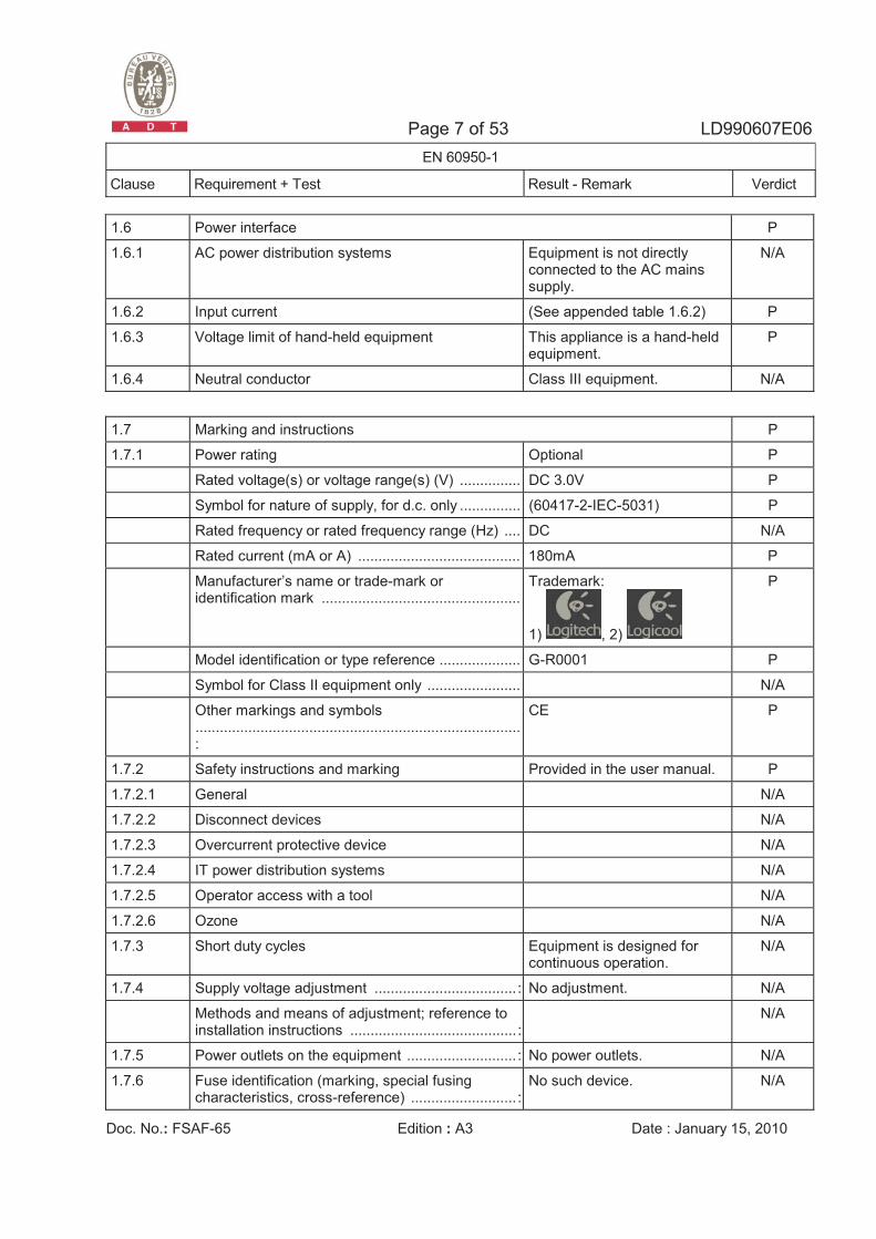
Manufacturer’s name or trade-mark or identification mark .................................................
Trademark:
1) , 2)
P
Model identification or type reference .................... G-R0001 P
Symbol for Class II equipment only ....................... N/A
Other markings and symbols ................................................................................:
CE P
1.7.2 Safety instructions and marking Provided in the user manual. P
1.7.2.1 General N/A
1.7.2.2 Disconnect devices N/A
1.7.2.3 Overcurrent protective device N/A
1.7.2.4 IT power distribution systems N/A
1.7.2.5 Operator access with a tool N/A
1.7.2.6 Ozone N/A
1.7.3 Short duty cycles Equipment is designed for continuous operation.
N/A
1.7.4 Supply voltage adjustment ................................... : No adjustment. N/A
Methods and means of adjustment; reference to installation instructions ......................................... :
N/A
1.7.5 Power outlets on the equipment ........................... : No power outlets. N/A
1.7.6 Fuse identification (marking, special fusing characteristics, cross-reference) .......................... :
No such device. N/A
Page 8 of 53 LD990607E06 EN 60950-1
Clause Requirement + Test Result - Remark Verdict
Doc. No.: FSAF-65 Edition : A3 Date : January 15, 2010
1.7.7 Wiring terminals N/A
1.7.7.1 Protective earthing and bonding terminals ........... : Class III equipment. N/A
1.7.7.2 Terminals for a.c. mains supply conductors Class III equipment. N/A
1.7.7.3 Terminals for d.c. mains supply conductors N/A
1.7.8 Controls and indicators No safety affecting controls and indicators
N/A
1.7.8.1 Identification, location and marking ...................... : N/A
1.7.8.2 Colours ................................................................ : N/A
1.7.8.3 Symbols according to IEC 60417 ......................... : N/A
1.7.8.4 Markings using figures ....................................... : N/A
1.7.9 Isolation of multiple power sources ..................... : Only SELV supply. N/A
1.7.10 Thermostats and other regulating devices .......... : No thermostat or other regulating devices.
N/A
1.7.11 Durability The label was subjected to the test for permanence of marking. The label was rubbed with cloth for 15s. And then rubbed by the cloth soaked with Naphtha for 15s. After this test there was no damage to the label. The marking on the label did not fade. There was no curling nor lifting on the label edge.
P
1.7.12 Removable parts No removable parts. N/A
1.7.13 Replaceable batteries .......................................... : Consumer grade, one AA type non-rechargeable carbon-zinc or alkaline battery used.
N/A
Language(s) ........................................................ : ⎯
1.7.14 Equipment for restricted access locations............ : No restricted access location. N/A
2 PROTECTION FROM HAZARDS P
2.1 Protection from electric shock and energy hazards P
2.1.1 Protection in operator access areas Only SELV voltages. Furthermore there are no hazardous voltages generated internally. Therefore there are no protective measures required for the protection against electrical shock.
P
Page 9 of 53 LD990607E06 EN 60950-1
Clause Requirement + Test Result - Remark Verdict
Doc. No.: FSAF-65 Edition : A3 Date : January 15, 2010
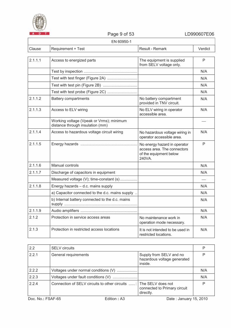
2.1.1.1 Access to energized parts The equipment is supplied from SELV voltage only.
P
Test by inspection .................................................. : N/A
Test with test finger (Figure 2A) ............................ : N/A
Test with test pin (Figure 2B) ................................ : N/A
Test with test probe (Figure 2C) ............................ : N/A
2.1.1.2 Battery compartments No battery compartment provided in TNV circuit.
N/A
2.1.1.3 Access to ELV wiring No ELV wiring in operator accessible area.
N/A
Working voltage (Vpeak or Vrms); minimum distance through insulation (mm)
⎯
2.1.1.4 Access to hazardous voltage circuit wiring No hazardous voltage wiring in operator accessible area.
N/A
2.1.1.5 Energy hazards ..................................................... : No energy hazard in operator access area. The connectors of the equipment below 240VA.
P
2.1.1.6 Manual controls N/A
2.1.1.7 Discharge of capacitors in equipment N/A
Measured voltage (V); time-constant (s) ................ : ⎯
2.1.1.8 Energy hazards – d.c. mains supply N/A
a) Capacitor connected to the d.c. mains supply .. : N/A
b) Internal battery connected to the d.c. mains supply .................................................................... :
N/A
2.1.1.9 Audio amplifiers ..................................................... : N/A
2.1.2 Protection in service access areas No maintenance work in operation mode necessary.
N/A
2.1.3 Protection in restricted access locations It is not intended to be used in restricted locations.
N/A
2.2 SELV circuits P
2.2.1 General requirements Supply from SELV and no hazardous voltage generated inside.
P
2.2.2 Voltages under normal conditions (V) ...................: N/A
2.2.3 Voltages under fault conditions (V) .......................: N/A
2.2.4 Connection of SELV circuits to other circuits ...... : The SELV does not connected to Primary circuit directly.
P
Page 10 of 53 LD990607E06 EN 60950-1
Clause Requirement + Test Result - Remark Verdict
Doc. No.: FSAF-65 Edition : A3 Date : January 15, 2010
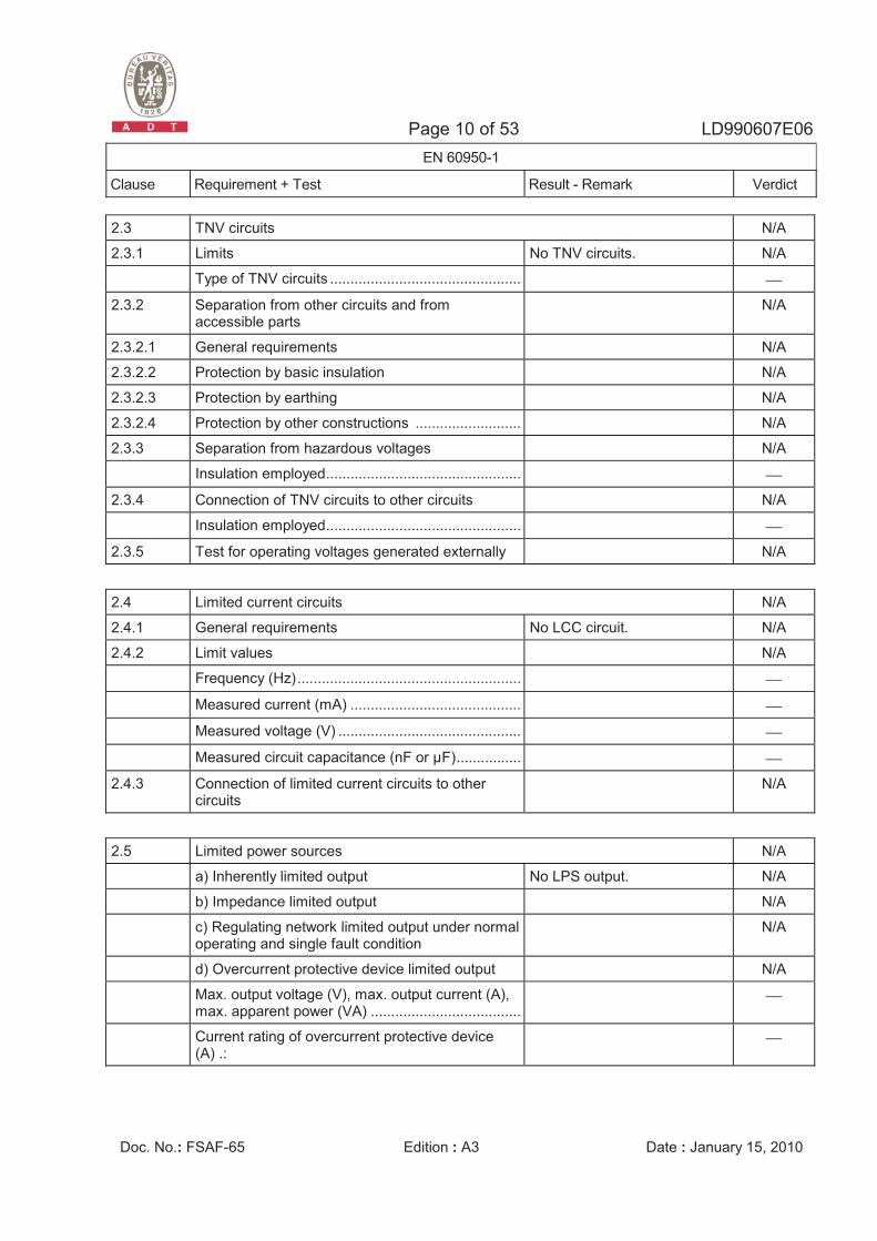
2.3 TNV circuits N/A
2.3.1 Limits No TNV circuits. N/A
Type of TNV circuits ...............................................: ⎯
2.3.2 Separation from other circuits and from accessible parts
N/A
2.3.2.1 General requirements N/A
2.3.2.2 Protection by basic insulation N/A
2.3.2.3 Protection by earthing N/A
2.3.2.4 Protection by other constructions ..........................: N/A
2.3.3 Separation from hazardous voltages N/A
Insulation employed................................................: ⎯
2.3.4 Connection of TNV circuits to other circuits N/A
Insulation employed................................................: ⎯
2.3.5 Test for operating voltages generated externally N/A
2.4 Limited current circuits N/A
2.4.1 General requirements No LCC circuit. N/A
2.4.2 Limit values N/A
Frequency (Hz).......................................................: ⎯
Measured current (mA) .......................................... : ⎯
Measured voltage (V) ............................................. : ⎯
Measured circuit capacitance (nF or µF)................: ⎯
2.4.3 Connection of limited current circuits to other circuits
N/A
2.5 Limited power sources N/A
a) Inherently limited output No LPS output. N/A
b) Impedance limited output N/A
c) Regulating network limited output under normal operating and single fault condition
N/A
d) Overcurrent protective device limited output N/A
Max. output voltage (V), max. output current (A), max. apparent power (VA) .....................................:
⎯
Current rating of overcurrent protective device (A) .:
⎯
Page 11 of 53 LD990607E06 EN 60950-1
Clause Requirement + Test Result - Remark Verdict
Doc. No.: FSAF-65 Edition : A3 Date : January 15, 2010
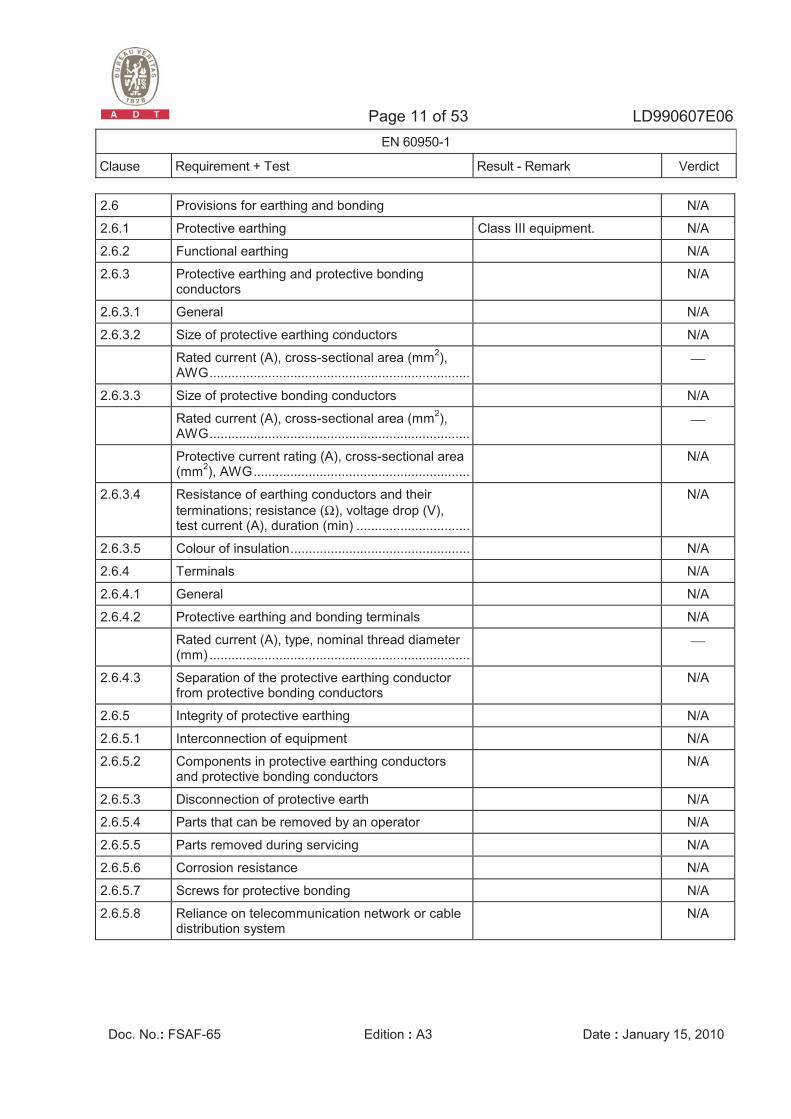
2.6 Provisions for earthing and bonding N/A
2.6.1 Protective earthing Class III equipment. N/A
2.6.2 Functional earthing N/A
2.6.3 Protective earthing and protective bonding conductors
N/A
2.6.3.1 General N/A
2.6.3.2 Size of protective earthing conductors N/A
Rated current (A), cross-sectional area (mm2), AWG.......................................................................:
⎯
2.6.3.3 Size of protective bonding conductors N/A
Rated current (A), cross-sectional area (mm2), AWG.......................................................................:
⎯
Protective current rating (A), cross-sectional area (mm2), AWG...........................................................:
N/A
2.6.3.4 Resistance of earthing conductors and their terminations; resistance (Ω), voltage drop (V), test current (A), duration (min) ...............................:
N/A
2.6.3.5 Colour of insulation.................................................: N/A
2.6.4 Terminals N/A
2.6.4.1 General N/A
2.6.4.2 Protective earthing and bonding terminals N/A
Rated current (A), type, nominal thread diameter (mm) .......................................................................:
⎯
2.6.4.3 Separation of the protective earthing conductor from protective bonding conductors
N/A
2.6.5 Integrity of protective earthing N/A
2.6.5.1 Interconnection of equipment N/A
2.6.5.2 Components in protective earthing conductors and protective bonding conductors
N/A
2.6.5.3 Disconnection of protective earth N/A
2.6.5.4 Parts that can be removed by an operator N/A
2.6.5.5 Parts removed during servicing N/A
2.6.5.6 Corrosion resistance N/A
2.6.5.7 Screws for protective bonding N/A
2.6.5.8 Reliance on telecommunication network or cable distribution system
N/A
Page 12 of 53 LD990607E06 EN 60950-1
Clause Requirement + Test Result - Remark Verdict
Doc. No.: FSAF-65 Edition : A3 Date : January 15, 2010
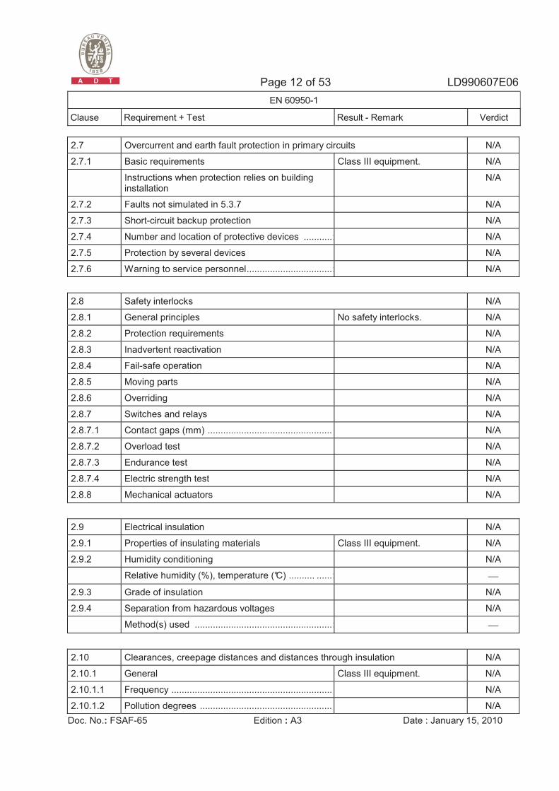
2.7 Overcurrent and earth fault protection in primary circuits N/A
2.7.1 Basic requirements Class III equipment. N/A
Instructions when protection relies on building installation
N/A
2.7.2 Faults not simulated in 5.3.7 N/A
2.7.3 Short-circuit backup protection N/A
2.7.4 Number and location of protective devices ...........: N/A
2.7.5 Protection by several devices N/A
2.7.6 Warning to service personnel.................................: N/A
2.8 Safety interlocks N/A
2.8.1 General principles No safety interlocks. N/A
2.8.2 Protection requirements N/A
2.8.3 Inadvertent reactivation N/A
2.8.4 Fail-safe operation N/A
2.8.5 Moving parts N/A
2.8.6 Overriding N/A
2.8.7 Switches and relays N/A
2.8.7.1 Contact gaps (mm) ................................................ N/A
2.8.7.2 Overload test N/A
2.8.7.3 Endurance test N/A
2.8.7.4 Electric strength test N/A
2.8.8 Mechanical actuators N/A
2.9 Electrical insulation N/A
2.9.1 Properties of insulating materials Class III equipment. N/A
2.9.2 Humidity conditioning N/A
Relative humidity (%), temperature (°C) .......... ......: ⎯
2.9.3 Grade of insulation N/A
2.9.4 Separation from hazardous voltages N/A
Method(s) used .....................................................: ⎯
2.10 Clearances, creepage distances and distances through insulation N/A
2.10.1 General Class III equipment. N/A
2.10.1.1 Frequency .............................................................. N/A
2.10.1.2 Pollution degrees ................................................... N/A
Page 13 of 53 LD990607E06 EN 60950-1
Clause Requirement + Test Result - Remark Verdict
Doc. No.: FSAF-65 Edition : A3 Date : January 15, 2010
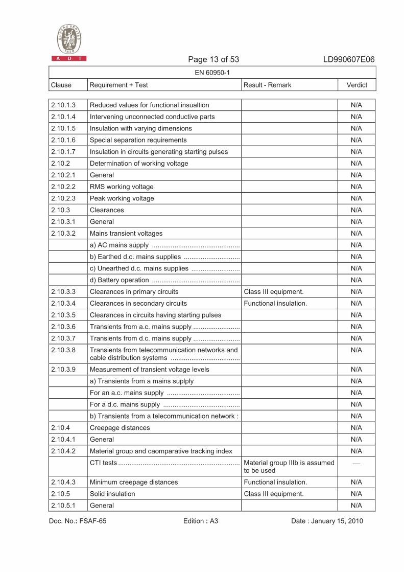
2.10.1.3 Reduced values for functional insualtion N/A
2.10.1.4 Intervening unconnected conductive parts N/A
2.10.1.5 Insulation with varying dimensions N/A
2.10.1.6 Special separation requirements N/A
2.10.1.7 Insulation in circuits generating starting pulses N/A
2.10.2 Determination of working voltage N/A
2.10.2.1 General N/A
2.10.2.2 RMS working voltage N/A
2.10.2.3 Peak working voltage N/A
2.10.3 Clearances N/A
2.10.3.1 General N/A
2.10.3.2 Mains transient voltages N/A
a) AC mains supply ............................................... N/A
b) Earthed d.c. mains supplies .............................. N/A
c) Unearthed d.c. mains supplies .......................... N/A
d) Battery operation ............................................... N/A
2.10.3.3 Clearances in primary circuits Class III equipment. N/A
2.10.3.4 Clearances in secondary circuits Functional insulation. N/A
2.10.3.5 Clearances in circuits having starting pulses N/A
2.10.3.6 Transients from a.c. mains supply ......................... N/A
2.10.3.7 Transients from d.c. mains supply ......................... N/A
2.10.3.8 Transients from telecommunication networks and cable distribution systems .....................................
N/A
2.10.3.9 Measurement of transient voltage levels N/A
a) Transients from a mains suplply N/A
For an a.c. mains supply ....................................... N/A
For a d.c. mains supply ......................................... N/A
b) Transients from a telecommunication network : N/A
2.10.4 Creepage distances N/A
2.10.4.1 General N/A
2.10.4.2 Material group and caomparative tracking index N/A
CTI tests ................................................................. Material group IIIb is assumed to be used
⎯
2.10.4.3 Minimum creepage distances Functional insulation. N/A
2.10.5 Solid insulation Class III equipment. N/A
2.10.5.1 General N/A
Page 14 of 53 LD990607E06 EN 60950-1
Clause Requirement + Test Result - Remark Verdict
Doc. No.: FSAF-65 Edition : A3 Date : January 15, 2010
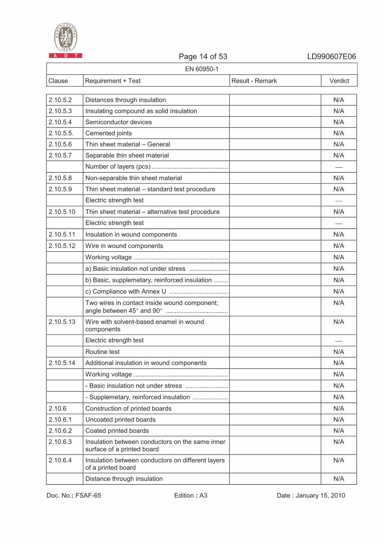
2.10.5.2 Distances through insulation N/A
2.10.5.3 Insulating compound as solid insulation N/A
2.10.5.4 Semiconductor devices N/A
2.10.5.5. Cemented joints N/A
2.10.5.6 Thin sheet material – General N/A
2.10.5.7 Separable thin sheet material N/A
Number of layers (pcs) ........................................... ⎯
2.10.5.8 Non-separable thin sheet material N/A
2.10.5.9 Thin sheet material – standard test procedure N/A
Electric strength test ⎯
2.10.5.10 Thin sheet material – alternative test procedure N/A
Electric strength test ⎯
2.10.5.11 Insulation in wound components N/A
2.10.5.12 Wire in wound components N/A
Working voltage ..................................................... N/A
a) Basic insulation not under stress ...................... N/A
b) Basic, supplemetary, reinforced insulation ........ N/A
c) Compliance with Annex U ................................. N/A
Two wires in contact inside wound component; angle between 45° and 90° ...................................
N/A
2.10.5.13 Wire with solvent-based enamel in wound components
N/A
Electric strength test ⎯
Routine test N/A
2.10.5.14 Additional insulation in wound components N/A
Working voltage ..................................................... N/A
- Basic insulation not under stress ........................ N/A
- Supplemetary, reinforced insulation .................... N/A
2.10.6 Construction of printed boards N/A
2.10.6.1 Uncoated printed boards N/A
2.10.6.2 Coated printed boards N/A
2.10.6.3 Insulation between conductors on the same inner surface of a printed board
N/A
2.10.6.4 Insulation between conductors on different layers of a printed board
N/A
Distance through insulation N/A

Page 15 of 53 LD990607E06 EN 60950-1
Clause Requirement + Test Result - Remark Verdict
Doc. No.: FSAF-65 Edition : A3 Date : January 15, 2010
Number of insulation layers (pcs)........................... N/A
2.10.7 Component external terminations N/A
2.10.8 Tests on coated printed boards and coated components
N/A
2.10.8.1 Sample preparation and preliminary inspection N/A
2.10.8.2 Thermal conditioning N/A
2.10.8.3 Electric strength test N/A
2.10.8.4 Abrasion resistance test N/A
2.10.9 Thermal cycling N/A
2.10.10 Test for Pollution Degree 1 environment and insulating compound
N/A
2.10.11 Tests for semiconductor devices and cemented joints
N/A
2.10.12 Enclosed and sealed parts N/A
3 WIRING, CONNECTIONS AND SUPPLY N/A
3.1 General N/A
3.1.1 Current rating and overcurrent protection Class III equipment. N/A
3.1.2 Protection against mechanical damage N/A
3.1.3 Securing of internal wiring N/A
3.1.4 Insulation of conductors N/A
3.1.5 Beads and ceramic insulators N/A
3.1.6 Screws for electrical contact pressure N/A
3.1.7 Insulating materials in electrical connections N/A
3.1.8 Self-tapping and spaced thread screws N/A
3.1.9 Termination of conductors N/A
10 N pull test N/A
3.1.10 Sleeving on wiring N/A
3.2 Connection to a mains supply N/A
3.2.1 Means of connection Class III equipment. N/A
3.2.1.1 Connection to an a.c. mains supply N/A
3.2.1.2 Connection to a d.c. mains supply N/A
3.2.2 Multiple supply connections N/A
3.2.3 Permanently connected equipment N/A
Page 16 of 53 LD990607E06 EN 60950-1
Clause Requirement + Test Result - Remark Verdict
Doc. No.: FSAF-65 Edition : A3 Date : January 15, 2010
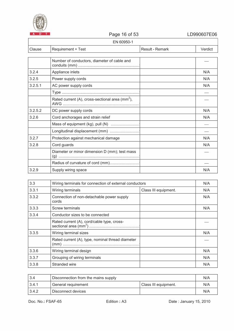
Number of conductors, diameter of cable and conduits (mm) ........................................................:
⎯
3.2.4 Appliance inlets N/A
3.2.5 Power supply cords N/A
3.2.5.1 AC power supply cords N/A
Type .......................................................................: ⎯
Rated current (A), cross-sectional area (mm2), AWG ......................................................................:
⎯
3.2.5.2 DC power supply cords N/A
3.2.6 Cord anchorages and strain relief N/A
Mass of equipment (kg), pull (N) ..........................: ⎯
Longitudinal displacement (mm) ...........................: ⎯
3.2.7 Protection against mechanical damage N/A
3.2.8 Cord guards N/A
Diameter or minor dimension D (mm); test mass (g) ..........................................................................:
⎯
Radius of curvature of cord (mm)...........................: ⎯
3.2.9 Supply wiring space N/A
3.3 Wiring terminals for connection of external conductors N/A
3.3.1 Wiring terminals Class III equipment. N/A
3.3.2 Connection of non-detachable power supply cords
N/A
3.3.3 Screw terminals N/A
3.3.4 Conductor sizes to be connected
Rated current (A), cord/cable type, cross-sectional area (mm2) ..............................................:
⎯
3.3.5 Wiring terminal sizes N/A
Rated current (A), type, nominal thread diameter (mm) ......................................................................:
⎯
3.3.6 Wiring terminal design N/A
3.3.7 Grouping of wiring terminals N/A
3.3.8 Stranded wire N/A
3.4 Disconnection from the mains supply N/A
3.4.1 General requirement Class III equipment. N/A
3.4.2 Disconnect devices N/A
Page 17 of 53 LD990607E06 EN 60950-1
Clause Requirement + Test Result - Remark Verdict
Doc. No.: FSAF-65 Edition : A3 Date : January 15, 2010
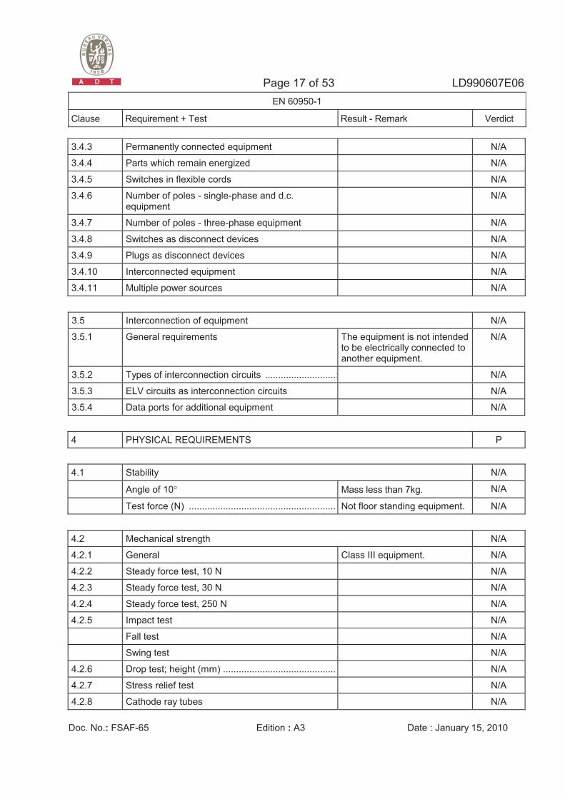
3.4.3 Permanently connected equipment N/A
3.4.4 Parts which remain energized N/A
3.4.5 Switches in flexible cords N/A
3.4.6 Number of poles - single-phase and d.c. equipment
N/A
3.4.7 Number of poles - three-phase equipment N/A
3.4.8 Switches as disconnect devices N/A
3.4.9 Plugs as disconnect devices N/A
3.4.10 Interconnected equipment N/A
3.4.11 Multiple power sources N/A
3.5 Interconnection of equipment N/A
3.5.1 General requirements The equipment is not intended to be electrically connected to another equipment.
N/A
3.5.2 Types of interconnection circuits ...........................: N/A
3.5.3 ELV circuits as interconnection circuits N/A
3.5.4 Data ports for additional equipment N/A
4 PHYSICAL REQUIREMENTS P
4.1 Stability N/A
Angle of 10° Mass less than 7kg. N/A
Test force (N) ........................................................ : Not floor standing equipment. N/A
4.2 Mechanical strength N/A
4.2.1 General Class III equipment. N/A
4.2.2 Steady force test, 10 N N/A
4.2.3 Steady force test, 30 N N/A
4.2.4 Steady force test, 250 N N/A
4.2.5 Impact test N/A
Fall test N/A
Swing test N/A
4.2.6 Drop test; height (mm) ........................................... : N/A
4.2.7 Stress relief test N/A
4.2.8 Cathode ray tubes N/A
Page 18 of 53 LD990607E06 EN 60950-1
Clause Requirement + Test Result - Remark Verdict
Doc. No.: FSAF-65 Edition : A3 Date : January 15, 2010
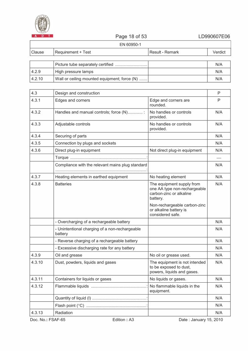
Picture tube separately certified ............................ : N/A
4.2.9 High pressure lamps N/A
4.2.10 Wall or ceiling mounted equipment; force (N) ....... : N/A
4.3 Design and construction P
4.3.1 Edges and corners Edge and corners are rounded.
P
4.3.2 Handles and manual controls; force (N)............. : No handles or controls provided.
N/A
4.3.3 Adjustable controls No handles or controls provided.
N/A
4.3.4 Securing of parts N/A
4.3.5 Connection by plugs and sockets N/A
4.3.6 Direct plug-in equipment Not direct plug-in equipment N/A
Torque .................................................................. : ⎯
Compliance with the relevant mains plug standard ............................................................................... :
N/A
4.3.7 Heating elements in earthed equipment No heating element N/A
4.3.8 Batteries The equipment supply from one AA type non-rechargeable carbon-zinc or alkaline battery. Non-rechargeable carbon-zinc or alkaline battery is considered safe.
N/A
- Overcharging of a rechargeable battery N/A
- Unintentional charging of a non-rechargeable battery
N/A
- Reverse charging of a rechargeable battery N/A
- Excessive discharging rate for any battery N/A
4.3.9 Oil and grease No oil or grease used. N/A
4.3.10 Dust, powders, liquids and gases The equipment is not intended to be exposed to dust, powers, liquids and gases.
N/A
4.3.11 Containers for liquids or gases No liquids or gases. N/A
4.3.12 Flammable liquids ................................................ : No flammable liquids in the equipment.
N/A
Quantity of liquid (l) ............................................... : N/A
Flash point (°C) .................................................... : N/A
4.3.13 Radiation N/A
Page 19 of 53 LD990607E06 EN 60950-1
Clause Requirement + Test Result - Remark Verdict
Doc. No.: FSAF-65 Edition : A3 Date : January 15, 2010
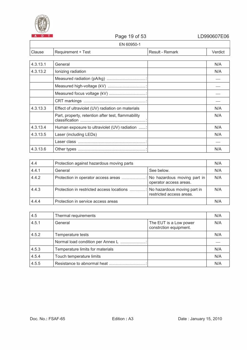
4.3.13.1 General N/A
4.3.13.2 Ionizing radiation N/A
Measured radiation (pA/kg) .................................. : ⎯
Measured high-voltage (kV) ................................. : ⎯
Measured focus voltage (kV) ................................ : ⎯
CRT markings ...................................................... : ⎯
4.3.13.3 Effect of ultraviolet (UV) radiation on materials N/A
Part, property, retention after test, flammability classification ......................................................... :
N/A
4.3.13.4 Human exposure to ultraviolet (UV) radiation ...... : N/A
4.3.13.5 Laser (including LEDs) N/A
Laser class ........................................................... : ⎯
4.3.13.6 Other types ........................................................... : N/A
4.4 Protection against hazardous moving parts N/A
4.4.1 General See below. N/A
4.4.2 Protection in operator access areas .....................: No hazardous moving part in operator access areas.
N/A
4.4.3 Protection in restricted access locations ..............: No hazardous moving part in restricted access areas.
N/A
4.4.4 Protection in service access areas N/A
4.5 Thermal requirements N/A
4.5.1 General The EUT is a Low power constrction equipment.
N/A
4.5.2 Temperature tests N/A
Normal load condition per Annex L ......................: ⎯
4.5.3 Temperature limits for materials N/A
4.5.4 Touch temperature limits N/A
4.5.5 Resistance to abnormal heat ................................: N/A
Page 20 of 53 LD990607E06 EN 60950-1
Clause Requirement + Test Result - Remark Verdict
Doc. No.: FSAF-65 Edition : A3 Date : January 15, 2010
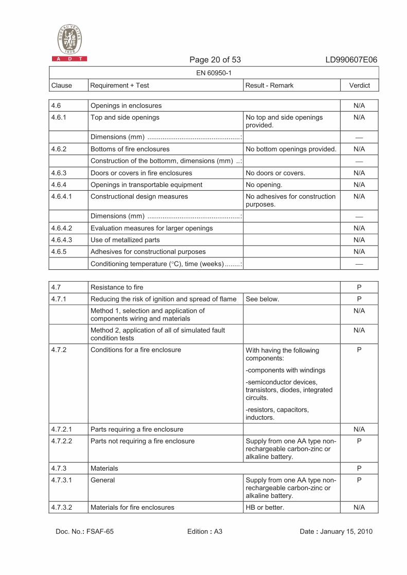
4.6 Openings in enclosures N/A
4.6.1 Top and side openings No top and side openings provided.
N/A
Dimensions (mm) .................................................: ⎯
4.6.2 Bottoms of fire enclosures No bottom openings provided. N/A
Construction of the bottomm, dimensions (mm) ..: ⎯
4.6.3 Doors or covers in fire enclosures No doors or covers. N/A
4.6.4 Openings in transportable equipment No opening. N/A
4.6.4.1 Constructional design measures No adhesives for construction purposes.
N/A
Dimensions (mm) .................................................: ⎯
4.6.4.2 Evaluation measures for larger openings N/A
4.6.4.3 Use of metallized parts N/A
4.6.5 Adhesives for constructional purposes N/A
Conditioning temperature (°C), time (weeks) ........: ⎯
4.7 Resistance to fire P
4.7.1 Reducing the risk of ignition and spread of flame See below. P
Method 1, selection and application of components wiring and materials
N/A
Method 2, application of all of simulated fault condition tests
N/A
4.7.2 Conditions for a fire enclosure With having the following components:
-components with windings
-semiconductor devices, transistors, diodes, integrated circuits.
-resistors, capacitors, inductors.
P
4.7.2.1 Parts requiring a fire enclosure N/A
4.7.2.2 Parts not requiring a fire enclosure Supply from one AA type non-rechargeable carbon-zinc or alkaline battery.
P
4.7.3 Materials P
4.7.3.1 General Supply from one AA type non-rechargeable carbon-zinc or alkaline battery.
P
4.7.3.2 Materials for fire enclosures HB or better. N/A
Page 21 of 53 LD990607E06 EN 60950-1
Clause Requirement + Test Result - Remark Verdict
Doc. No.: FSAF-65 Edition : A3 Date : January 15, 2010
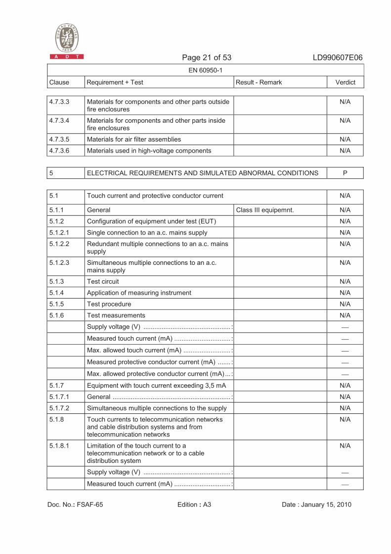
4.7.3.3 Materials for components and other parts outside fire enclosures
N/A
4.7.3.4 Materials for components and other parts inside fire enclosures
N/A
4.7.3.5 Materials for air filter assemblies N/A
4.7.3.6 Materials used in high-voltage components N/A
5 ELECTRICAL REQUIREMENTS AND SIMULATED ABNORMAL CONDITIONS P
5.1 Touch current and protective conductor current N/A
5.1.1 General Class III equipemnt. N/A
5.1.2 Configuration of equipment under test (EUT) N/A
5.1.2.1 Single connection to an a.c. mains supply N/A
5.1.2.2 Redundant multiple connections to an a.c. mains supply
N/A
5.1.2.3 Simultaneous multiple connections to an a.c. mains supply
N/A
5.1.3 Test circuit N/A
5.1.4 Application of measuring instrument N/A
5.1.5 Test procedure N/A
5.1.6 Test measurements N/A
Supply voltage (V) ................................................ : ⎯
Measured touch current (mA) ............................... : ⎯
Max. allowed touch current (mA) .......................... : ⎯
Measured protective conductor current (mA) ....... : ⎯
Max. allowed protective conductor current (mA) ... : ⎯
5.1.7 Equipment with touch current exceeding 3,5 mA N/A
5.1.7.1 General ................................................................. : N/A
5.1.7.2 Simultaneous multiple connections to the supply N/A
5.1.8 Touch currents to telecommunication networks and cable distribution systems and from telecommunication networks
N/A
5.1.8.1 Limitation of the touch current to a telecommunication network or to a cable distribution system
N/A
Supply voltage (V) ................................................ : ⎯
Measured touch current (mA) ............................... : ⎯
Page 22 of 53 LD990607E06 EN 60950-1
Clause Requirement + Test Result - Remark Verdict
Doc. No.: FSAF-65 Edition : A3 Date : January 15, 2010
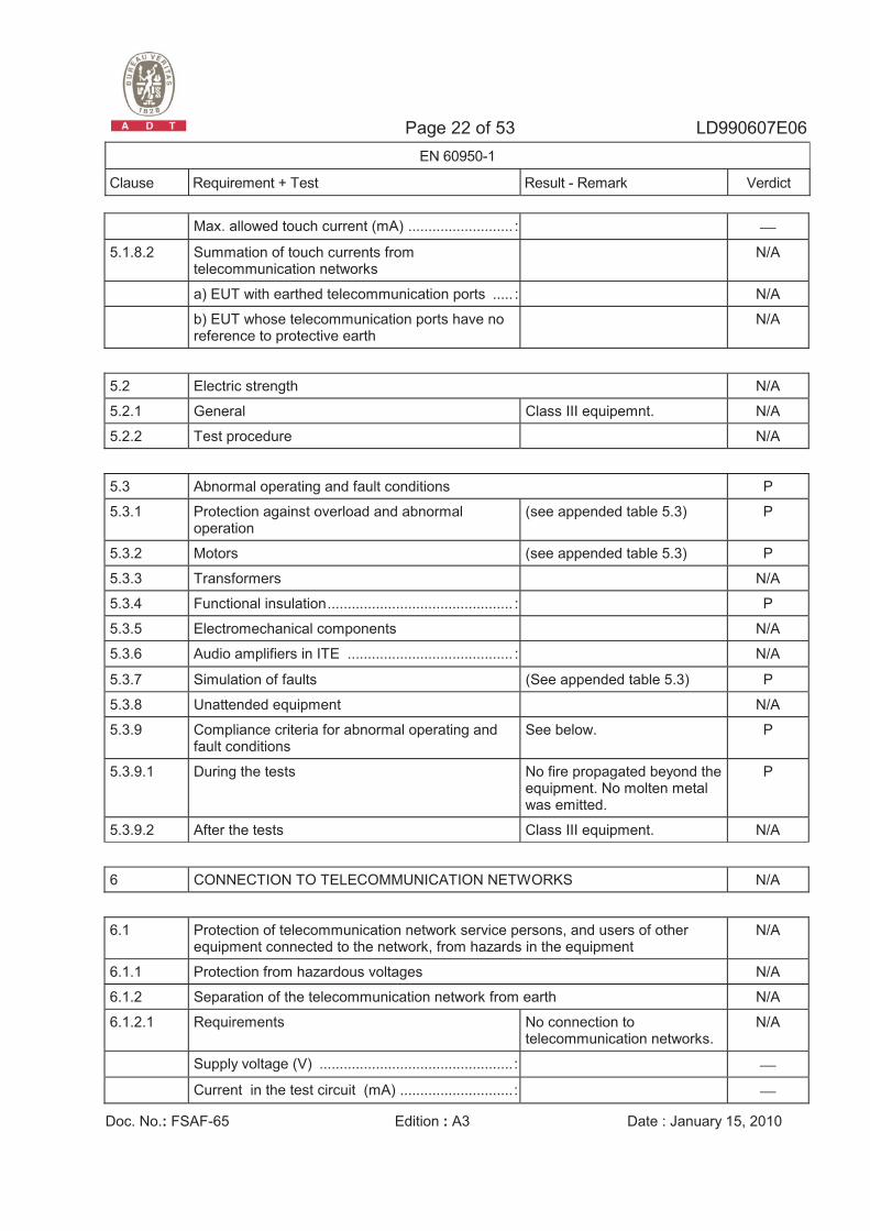
Max. allowed touch current (mA) .......................... : ⎯
5.1.8.2 Summation of touch currents from telecommunication networks
N/A
a) EUT with earthed telecommunication ports ..... : N/A
b) EUT whose telecommunication ports have no reference to protective earth
N/A
5.2 Electric strength N/A
5.2.1 General Class III equipemnt. N/A
5.2.2 Test procedure N/A
5.3 Abnormal operating and fault conditions P
5.3.1 Protection against overload and abnormal operation
(see appended table 5.3) P
5.3.2 Motors (see appended table 5.3) P
5.3.3 Transformers N/A
5.3.4 Functional insulation.............................................. : P
5.3.5 Electromechanical components N/A
5.3.6 Audio amplifiers in ITE ......................................... : N/A
5.3.7 Simulation of faults (See appended table 5.3) P
5.3.8 Unattended equipment N/A
5.3.9 Compliance criteria for abnormal operating and fault conditions
See below. P
5.3.9.1 During the tests No fire propagated beyond the equipment. No molten metal was emitted.
P
5.3.9.2 After the tests Class III equipment. N/A
6 CONNECTION TO TELECOMMUNICATION NETWORKS N/A
6.1 Protection of telecommunication network service persons, and users of other equipment connected to the network, from hazards in the equipment
N/A
6.1.1 Protection from hazardous voltages N/A
6.1.2 Separation of the telecommunication network from earth N/A
6.1.2.1 Requirements No connection to telecommunication networks.
N/A
Supply voltage (V) ................................................ : ⎯
Current in the test circuit (mA) ............................ : ⎯
Page 23 of 53 LD990607E06 EN 60950-1
Clause Requirement + Test Result - Remark Verdict
Doc. No.: FSAF-65 Edition : A3 Date : January 15, 2010
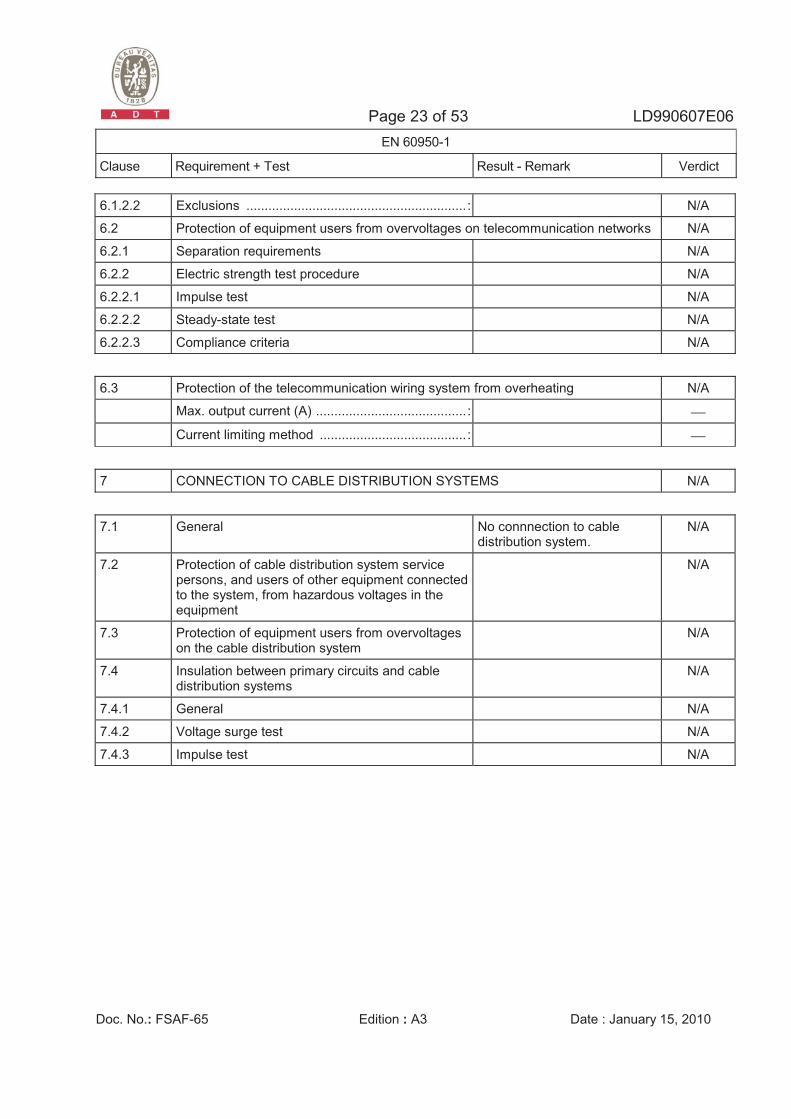
6.1.2.2 Exclusions ............................................................ : N/A
6.2 Protection of equipment users from overvoltages on telecommunication networks N/A
6.2.1 Separation requirements N/A
6.2.2 Electric strength test procedure N/A
6.2.2.1 Impulse test N/A
6.2.2.2 Steady-state test N/A
6.2.2.3 Compliance criteria N/A
6.3 Protection of the telecommunication wiring system from overheating N/A
Max. output current (A) ......................................... : ⎯
Current limiting method ........................................ : ⎯
7 CONNECTION TO CABLE DISTRIBUTION SYSTEMS N/A
7.1 General No connnection to cable distribution system.
N/A
7.2 Protection of cable distribution system service persons, and users of other equipment connected to the system, from hazardous voltages in the equipment
N/A
7.3 Protection of equipment users from overvoltages on the cable distribution system
N/A
7.4 Insulation between primary circuits and cable distribution systems
N/A
7.4.1 General N/A
7.4.2 Voltage surge test N/A
7.4.3 Impulse test N/A
Page 24 of 53 LD990607E06 EN 60950-1
Clause Requirement + Test Result - Remark Verdict
Doc. No.: FSAF-65 Edition : A3 Date : January 15, 2010
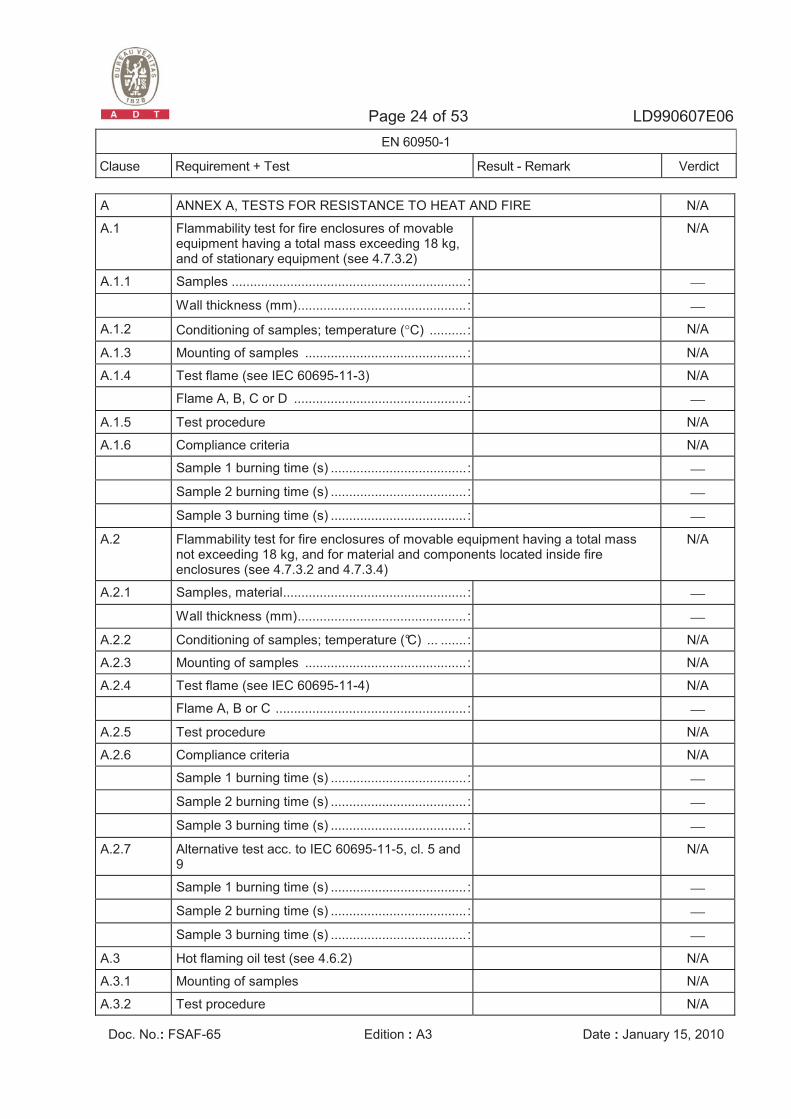
A ANNEX A, TESTS FOR RESISTANCE TO HEAT AND FIRE N/A
A.1 Flammability test for fire enclosures of movable equipment having a total mass exceeding 18 kg, and of stationary equipment (see 4.7.3.2)
N/A
A.1.1 Samples ................................................................ : ⎯
Wall thickness (mm).............................................. : ⎯
A.1.2 Conditioning of samples; temperature (°C) .......... : N/A
A.1.3 Mounting of samples ............................................ : N/A
A.1.4 Test flame (see IEC 60695-11-3) N/A
Flame A, B, C or D ............................................... : ⎯
A.1.5 Test procedure N/A
A.1.6 Compliance criteria N/A
Sample 1 burning time (s) ..................................... : ⎯
Sample 2 burning time (s) ..................................... : ⎯
Sample 3 burning time (s) ..................................... : ⎯
A.2 Flammability test for fire enclosures of movable equipment having a total mass not exceeding 18 kg, and for material and components located inside fire enclosures (see 4.7.3.2 and 4.7.3.4)
N/A
A.2.1 Samples, material.................................................. : ⎯
Wall thickness (mm).............................................. : ⎯
A.2.2 Conditioning of samples; temperature (°C) ... ....... : N/A
A.2.3 Mounting of samples ............................................ : N/A
A.2.4 Test flame (see IEC 60695-11-4) N/A
Flame A, B or C .................................................... : ⎯
A.2.5 Test procedure N/A
A.2.6 Compliance criteria N/A
Sample 1 burning time (s) ..................................... : ⎯
Sample 2 burning time (s) ..................................... : ⎯
Sample 3 burning time (s) ..................................... : ⎯
A.2.7 Alternative test acc. to IEC 60695-11-5, cl. 5 and 9
N/A
Sample 1 burning time (s) ..................................... : ⎯
Sample 2 burning time (s) ..................................... : ⎯
Sample 3 burning time (s) ..................................... : ⎯
A.3 Hot flaming oil test (see 4.6.2) N/A
A.3.1 Mounting of samples N/A
A.3.2 Test procedure N/A
Page 25 of 53 LD990607E06 EN 60950-1
Clause Requirement + Test Result - Remark Verdict
Doc. No.: FSAF-65 Edition : A3 Date : January 15, 2010
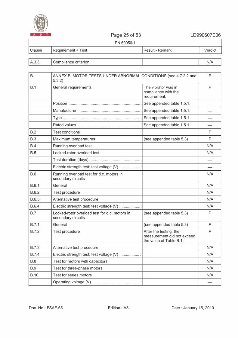
A.3.3 Compliance criterion N/A
B ANNEX B, MOTOR TESTS UNDER ABNORMAL CONDITIONS (see 4.7.2.2 and 5.3.2)
P
B.1 General requirements The vibrator was in compliance with the requirement.
P
Position ................................................................. : See appended table 1.5.1. ⎯
Manufacturer ........................................................ : See appended table 1.5.1. ⎯
Type ...................................................................... : See appended table 1.5.1. ⎯
Rated values ........................................................ : See appended table 1.5.1. ⎯
B.2 Test conditions P
B.3 Maximum temperatures (see appended table 5.3) P
B.4 Running overload test N/A
B.5 Locked-rotor overload test N/A
Test duration (days) .............................................. : ⎯
Electric strength test: test voltage (V) ................... : ⎯
B.6 Running overload test for d.c. motors in secondary circuits
N/A
B.6.1 General N/A
B.6.2 Test procedure N/A
B.6.3 Alternative test procedure N/A
B.6.4 Electric strength test; test voltage (V) ................... : N/A
B.7 Locked-rotor overload test for d.c. motors in secondary circuits
(see appended table 5.3) P
B.7.1 General (see appended table 5.3) P
B.7.2 Test procedure After the testing, the measurement did not exceed the value of Table B.1.
P
B.7.3 Alternative test procedure N/A
B.7.4 Electric strength test; test voltage (V) .................. : N/A
B.8 Test for motors with capacitors N/A
B.9 Test for three-phase motors N/A
B.10 Test for series motors N/A
Operating voltage (V) ........................................... : ⎯
Page 26 of 53 LD990607E06 EN 60950-1
Clause Requirement + Test Result - Remark Verdict
Doc. No.: FSAF-65 Edition : A3 Date : January 15, 2010
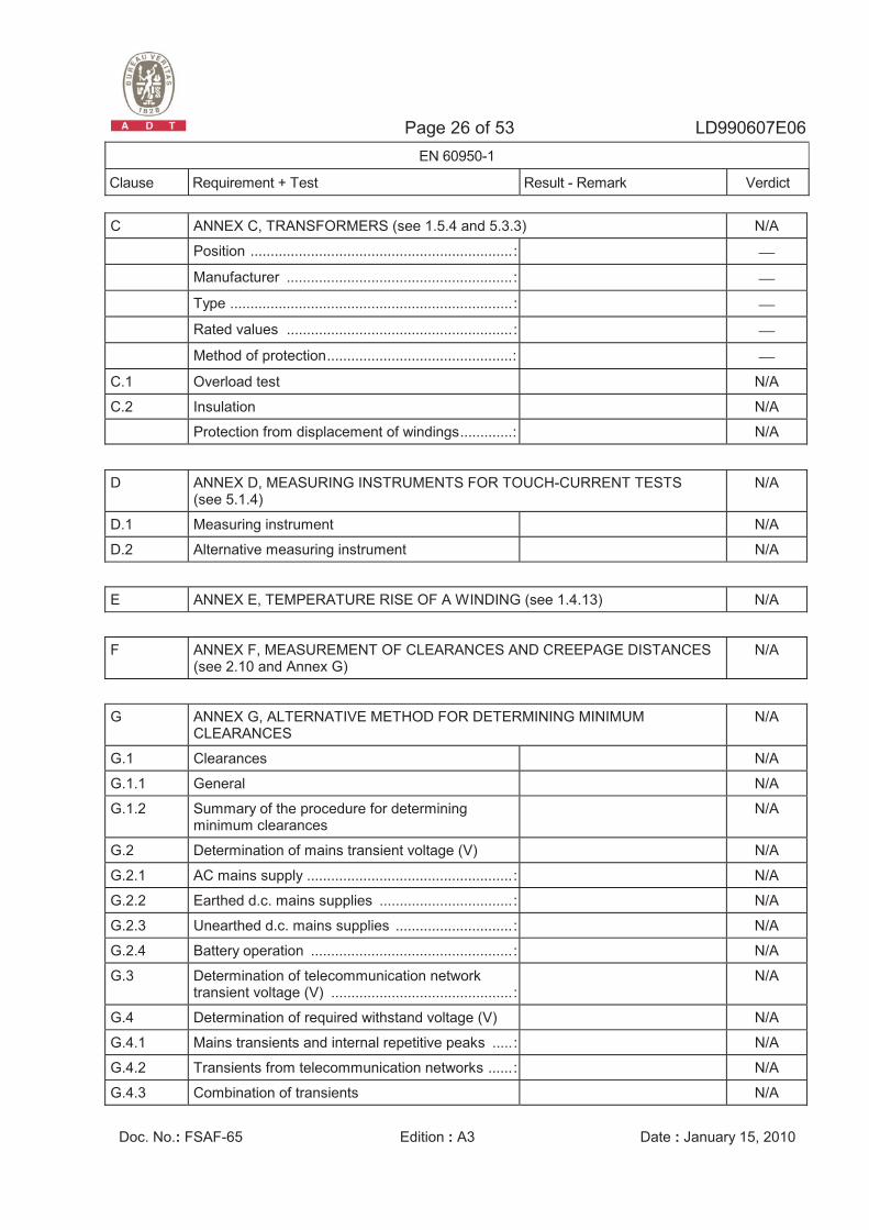
C ANNEX C, TRANSFORMERS (see 1.5.4 and 5.3.3) N/A
Position ................................................................. : ⎯
Manufacturer ........................................................ : ⎯
Type ...................................................................... : ⎯
Rated values ........................................................ : ⎯
Method of protection..............................................: ⎯
C.1 Overload test N/A
C.2 Insulation N/A
Protection from displacement of windings.............: N/A
D ANNEX D, MEASURING INSTRUMENTS FOR TOUCH-CURRENT TESTS (see 5.1.4)
N/A
D.1 Measuring instrument N/A
D.2 Alternative measuring instrument N/A
E ANNEX E, TEMPERATURE RISE OF A WINDING (see 1.4.13) N/A
F ANNEX F, MEASUREMENT OF CLEARANCES AND CREEPAGE DISTANCES (see 2.10 and Annex G)
N/A
G ANNEX G, ALTERNATIVE METHOD FOR DETERMINING MINIMUM CLEARANCES
N/A
G.1 Clearances N/A
G.1.1 General N/A
G.1.2 Summary of the procedure for determining minimum clearances
N/A
G.2 Determination of mains transient voltage (V) N/A
G.2.1 AC mains supply ................................................... : N/A
G.2.2 Earthed d.c. mains supplies ................................. : N/A
G.2.3 Unearthed d.c. mains supplies ............................. : N/A
G.2.4 Battery operation .................................................. : N/A
G.3 Determination of telecommunication network transient voltage (V) ............................................. :
N/A
G.4 Determination of required withstand voltage (V) N/A
G.4.1 Mains transients and internal repetitive peaks .....: N/A
G.4.2 Transients from telecommunication networks ...... : N/A
G.4.3 Combination of transients N/A
Page 27 of 53 LD990607E06 EN 60950-1
Clause Requirement + Test Result - Remark Verdict
Doc. No.: FSAF-65 Edition : A3 Date : January 15, 2010
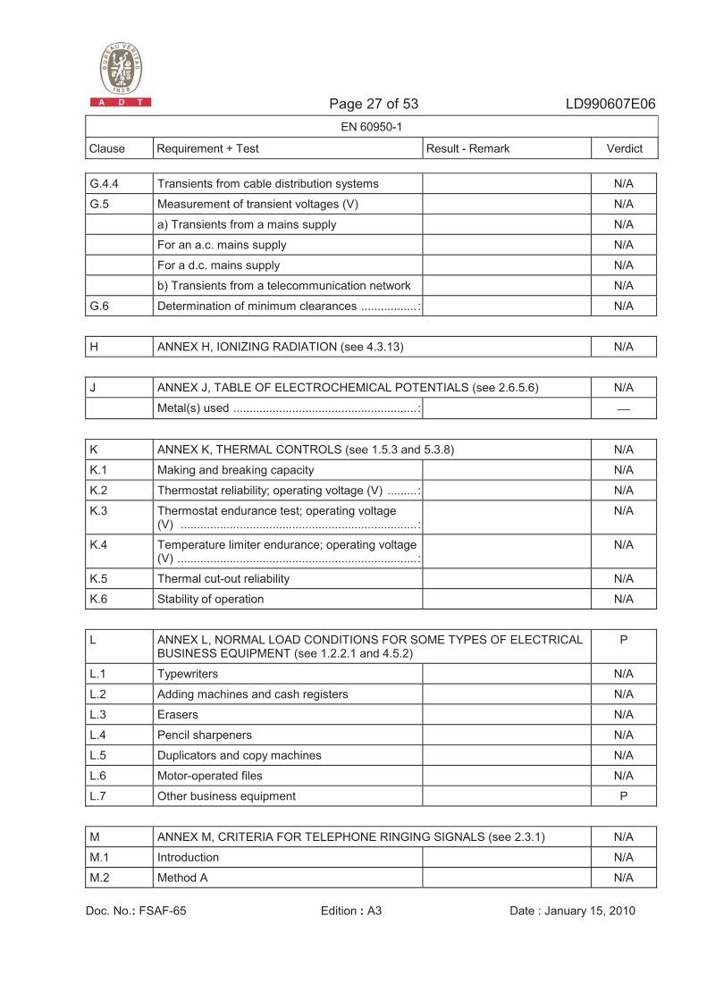
G.4.4 Transients from cable distribution systems N/A
G.5 Measurement of transient voltages (V) N/A
a) Transients from a mains supply N/A
For an a.c. mains supply N/A
For a d.c. mains supply N/A
b) Transients from a telecommunication network N/A
G.6 Determination of minimum clearances ................. : N/A
H ANNEX H, IONIZING RADIATION (see 4.3.13) N/A
J ANNEX J, TABLE OF ELECTROCHEMICAL POTENTIALS (see 2.6.5.6) N/A
Metal(s) used ........................................................ : ⎯
K ANNEX K, THERMAL CONTROLS (see 1.5.3 and 5.3.8) N/A
K.1 Making and breaking capacity N/A
K.2 Thermostat reliability; operating voltage (V) ......... : N/A
K.3 Thermostat endurance test; operating voltage (V) ........................................................................ :
N/A
K.4 Temperature limiter endurance; operating voltage (V) ......................................................................... :
N/A
K.5 Thermal cut-out reliability N/A
K.6 Stability of operation N/A
L ANNEX L, NORMAL LOAD CONDITIONS FOR SOME TYPES OF ELECTRICAL BUSINESS EQUIPMENT (see 1.2.2.1 and 4.5.2)
P
L.1 Typewriters N/A
L.2 Adding machines and cash registers N/A
L.3 Erasers N/A
L.4 Pencil sharpeners N/A
L.5 Duplicators and copy machines N/A
L.6 Motor-operated files N/A
L.7 Other business equipment P
M ANNEX M, CRITERIA FOR TELEPHONE RINGING SIGNALS (see 2.3.1) N/A
M.1 Introduction N/A
M.2 Method A N/A
Page 28 of 53 LD990607E06 EN 60950-1
Clause Requirement + Test Result - Remark Verdict
Doc. No.: FSAF-65 Edition : A3 Date : January 15, 2010
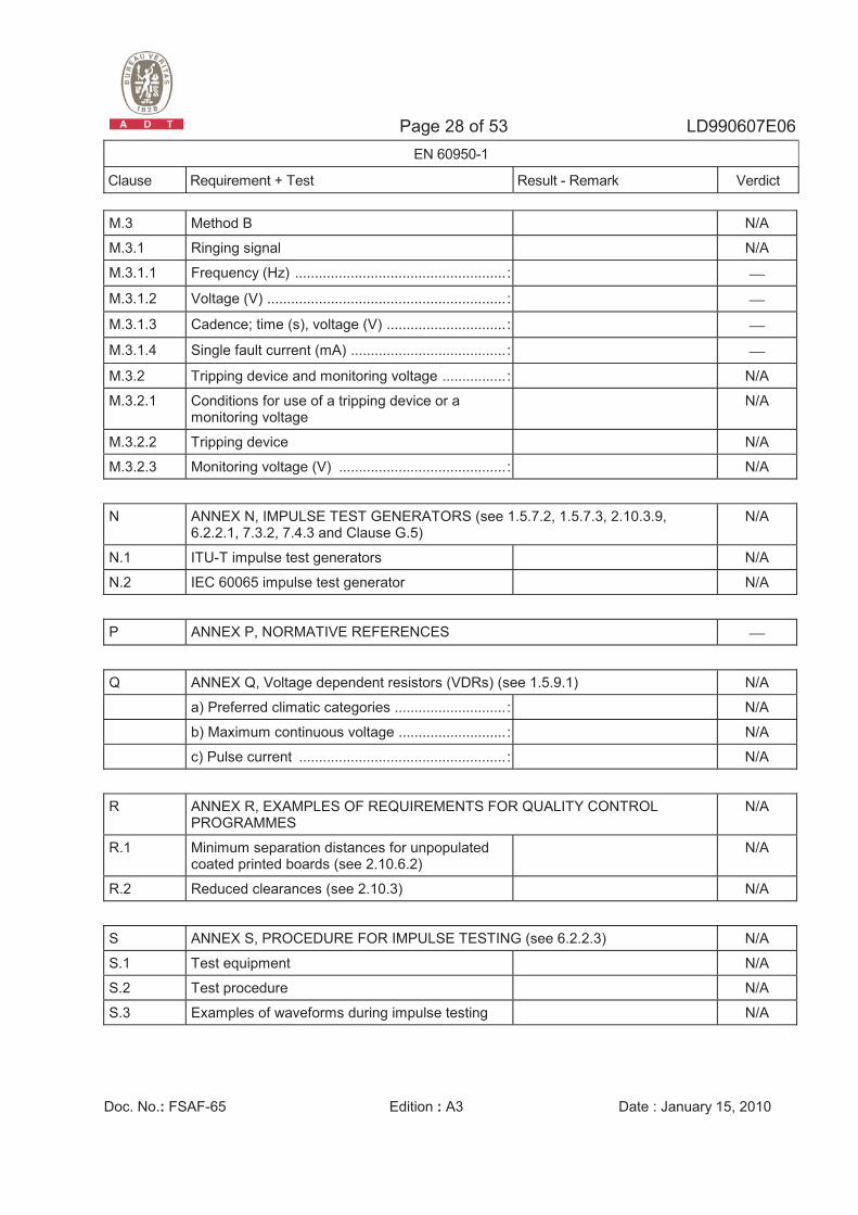
M.3 Method B N/A
M.3.1 Ringing signal N/A
M.3.1.1 Frequency (Hz) ..................................................... : ⎯
M.3.1.2 Voltage (V) ............................................................ : ⎯
M.3.1.3 Cadence; time (s), voltage (V) .............................. : ⎯
M.3.1.4 Single fault current (mA) ....................................... : ⎯
M.3.2 Tripping device and monitoring voltage ................ : N/A
M.3.2.1 Conditions for use of a tripping device or a monitoring voltage
N/A
M.3.2.2 Tripping device N/A
M.3.2.3 Monitoring voltage (V) .......................................... : N/A
N ANNEX N, IMPULSE TEST GENERATORS (see 1.5.7.2, 1.5.7.3, 2.10.3.9, 6.2.2.1, 7.3.2, 7.4.3 and Clause G.5)
N/A
N.1 ITU-T impulse test generators N/A
N.2 IEC 60065 impulse test generator N/A
P ANNEX P, NORMATIVE REFERENCES ⎯
Q ANNEX Q, Voltage dependent resistors (VDRs) (see 1.5.9.1) N/A
a) Preferred climatic categories ............................ : N/A
b) Maximum continuous voltage ........................... : N/A
c) Pulse current .................................................... : N/A
R ANNEX R, EXAMPLES OF REQUIREMENTS FOR QUALITY CONTROL PROGRAMMES
N/A
R.1 Minimum separation distances for unpopulated coated printed boards (see 2.10.6.2)
N/A
R.2 Reduced clearances (see 2.10.3) N/A
S ANNEX S, PROCEDURE FOR IMPULSE TESTING (see 6.2.2.3) N/A
S.1 Test equipment N/A
S.2 Test procedure N/A
S.3 Examples of waveforms during impulse testing N/A

Page 29 of 53 LD990607E06 EN 60950-1
Clause Requirement + Test Result - Remark Verdict
Doc. No.: FSAF-65 Edition : A3 Date : January 15, 2010
T ANNEX T, GUIDANCE ON PROTECTION AGAINST INGRESS OF WATER (see 1.1.2)
N/A
⎯
U ANNEX U, INSULATED WINDING WIRES FOR USE WITHOUT INTERLEAVED INSULATION (see 2.10.5.4)
N/A
⎯
V ANNEX V, AC POWER DISTRIBUTION SYSTEMS (see 1.6.1) N/A
V.1 Introduction N/A
V.2 TN power distribution systems N/A
W ANNEX W, SUMMATION OF TOUCH CURRENTS N/A
W.1 Touch current from electronic circuits N/A
W.1.1 Floating circuits N/A
W.1.2 Earthed circuits N/A
W.2 Interconnection of several equipments N/A
W.2.1 Isolation N/A
W.2.2 Common return, isolated from earth N/A
W.2.3 Common return, connected to protective earth N/A
X ANNEX X, MAXIMUM HEATING EFFECT IN TRANSFORMER TESTS (see clause C.1)
N/A
X.1 Determination of maximum input current N/A
X.2 Overload test procedure N/A
Y ANNEX Y, ULTRAVIOLET LIGHT CONDITIONING TEST (see 4.3.13.3) N/A
Y.1 Test apparatus ..................................................... : N/A
Y.2 Mounting of test samples ..................................... : N/A
Y.3 Carbon-arc light-exposure apparatus ................... : N/A
Y.4 Xenon-arc light exposure apparatus .................... : N/A
Z ANNEX Z, OVERVOLTAGE CATEGORIES (see 2.10.3.2 and Clause G.2) N/A
AA ANNEX AA, MANDREL TEST (see 2.10.5.8) N/A
BB ANNEX BB, CHANGES IN THE SECOND EDITION ⎯

Page 30 of 53 LD990607E06 EN 60950-1
Clause Requirement + Test Result - Remark Verdict
Doc. No.: FSAF-65 Edition : A3 Date : January 15, 2010
EN 60950-1:2006 + A11:2009 – CENELEC COMMON MODIFICATIONS
Contents Add the following annexes: Annex ZA (normative) Normative references to international publications with their corresponding European publications Annex ZB (normative) Special national conditions Annex ZC (informative) A-deviations
N/A
General Delete all the “country” notes in the reference document according to the following list: 1.4.8 Note 2 1.5.1 Note 2 & 3 1.5.7.1 Note 1.5.8 Note 2 1.5.9.4 Note 1.7.2.1 Note 4, 5 & 62.2.3 Note 2.2.4 Note 2.3.2 Note 2.3.2.1 Note 2 2.3.4 Note 2 2.6.3.3 Note 2 & 32.7.1 Note 2.10.3.2 Note 2 2.10.5.13 Note 3 3.2.1.1 Note 3.2.4 Note 3. 2.5.1 Note 2 4.3.6 Note 1 & 2 4.7 Note 4 4.7.2.2 Note 4.7.3.1 Note 2 5.1.7.1 Note 3 & 4 5.3.7 Note 1 6 Note 2 & 5 6.1.2.1 Note 2 6.1.2.2 Note 6.2.2 Note 6. 2.2.1 Note 2 6.2.2.2 Note 7.1 Note 3 7.2 Note 7.3 Note 1 & 2 G.2.1 Note 2 Annex H Note 2
N/A
1.3.Z1 Add the following subclause: 1.3.Z1 Exposure to excessive sound pressure The apparatus shall be so designed and constructed as to present no danger when used for its intended purpose, either in normal operating conditions or under fault conditions, particularly providing protection against exposure to excessive sound pressures from headphones or earphones. NOTE Z1 A new method of measurement is described in EN 50332-1, Sound system equipment: Headphones and earphones associated with portable audio equipment - Maximum sound pressure level measurement methodology and limit considerations - Part 1: General method for “one package equipment”, and in EN 50332-2, Sound system equipment: Headphones and earphones associated with portable audio equipment - Maximum sound pressure level measurement methodology and limit considerations - Part 2: Guidelines to associate sets with headphones coming from different manufacturers.
N/A
1.5.1 Add the following NOTE: NOTE Z1 The use of certain substances in electrical and electronic equipment is restricted within the EU: see Directive 2002/95/EC
N/A
1.7.2.1 Add the following NOTE: NOTE Z1 In addition, the instructions shall include, as far as applicable, a warning that excessive sound pressure from earphones and headphones can cause hearing loss
N/A
Page 31 of 53 LD990607E06 EN 60950-1
Clause Requirement + Test Result - Remark Verdict
Doc. No.: FSAF-65 Edition : A3 Date : January 15, 2010
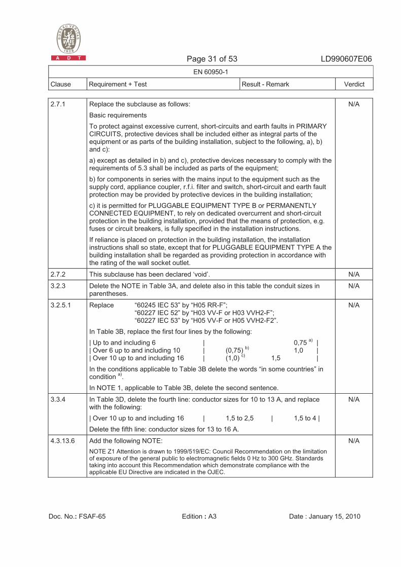
2.7.1 Replace the subclause as follows: Basic requirements To protect against excessive current, short-circuits and earth faults in PRIMARY CIRCUITS, protective devices shall be included either as integral parts of the equipment or as parts of the building installation, subject to the following, a), b) and c): a) except as detailed in b) and c), protective devices necessary to comply with the requirements of 5.3 shall be included as parts of the equipment; b) for components in series with the mains input to the equipment such as the supply cord, appliance coupler, r.f.i. filter and switch, short-circuit and earth fault protection may be provided by protective devices in the building installation; c) it is permitted for PLUGGABLE EQUIPMENT TYPE B or PERMANENTLY CONNECTED EQUIPMENT, to rely on dedicated overcurrent and short-circuit protection in the building installation, provided that the means of protection, e.g. fuses or circuit breakers, is fully specified in the installation instructions. If reliance is placed on protection in the building installation, the installation instructions shall so state, except that for PLUGGABLE EQUIPMENT TYPE A the building installation shall be regarded as providing protection in accordance with the rating of the wall socket outlet.
N/A
2.7.2 This subclause has been declared ‘void’. N/A
3.2.3 Delete the NOTE in Table 3A, and delete also in this table the conduit sizes in parentheses.
N/A
3.2.5.1 Replace “60245 IEC 53” by “H05 RR-F”; “60227 IEC 52” by “H03 VV-F or H03 VVH2-F”; “60227 IEC 53” by “H05 VV-F or H05 VVH2-F2”. In Table 3B, replace the first four lines by the following: | Up to and including 6 | 0,75 a) | | Over 6 up to and including 10 | (0,75) b) 1,0 | | Over 10 up to and including 16 | (1,0) c) 1,5 | In the conditions applicable to Table 3B delete the words “in some countries” in condition a). In NOTE 1, applicable to Table 3B, delete the second sentence.
N/A
3.3.4 In Table 3D, delete the fourth line: conductor sizes for 10 to 13 A, and replace with the following: | Over 10 up to and including 16 | 1,5 to 2,5 | 1,5 to 4 | Delete the fifth line: conductor sizes for 13 to 16 A.
N/A
4.3.13.6 Add the following NOTE: NOTE Z1 Attention is drawn to 1999/519/EC: Council Recommendation on the limitation of exposure of the general public to electromagnetic fields 0 Hz to 300 GHz. Standards taking into account this Recommendation which demonstrate compliance with the applicable EU Directive are indicated in the OJEC.
N/A
Page 32 of 53 LD990607E06 EN 60950-1
Clause Requirement + Test Result - Remark Verdict
Doc. No.: FSAF-65 Edition : A3 Date : January 15, 2010
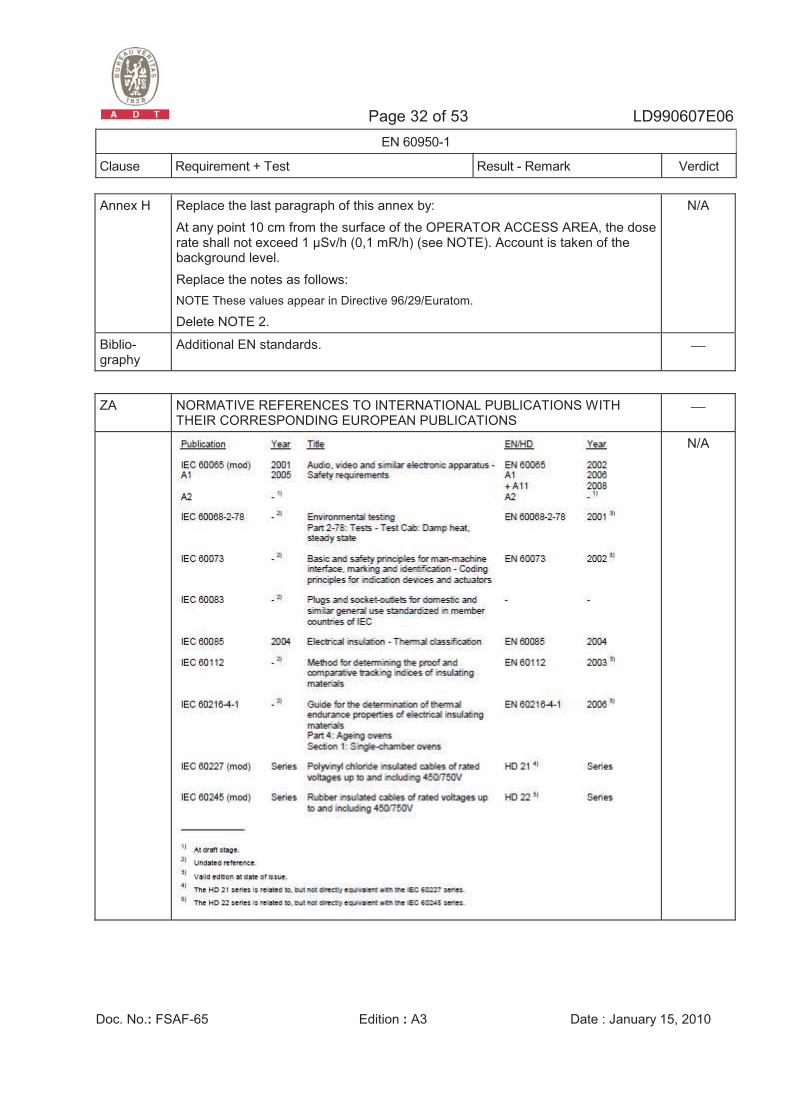
Annex H Replace the last paragraph of this annex by: At any point 10 cm from the surface of the OPERATOR ACCESS AREA, the dose rate shall not exceed 1 �Sv/h (0,1 mR/h) (see NOTE). Account is taken of the background level. Replace the notes as follows: NOTE These values appear in Directive 96/29/Euratom.
Delete NOTE 2.
N/A
Biblio-graphy
Additional EN standards. ⎯
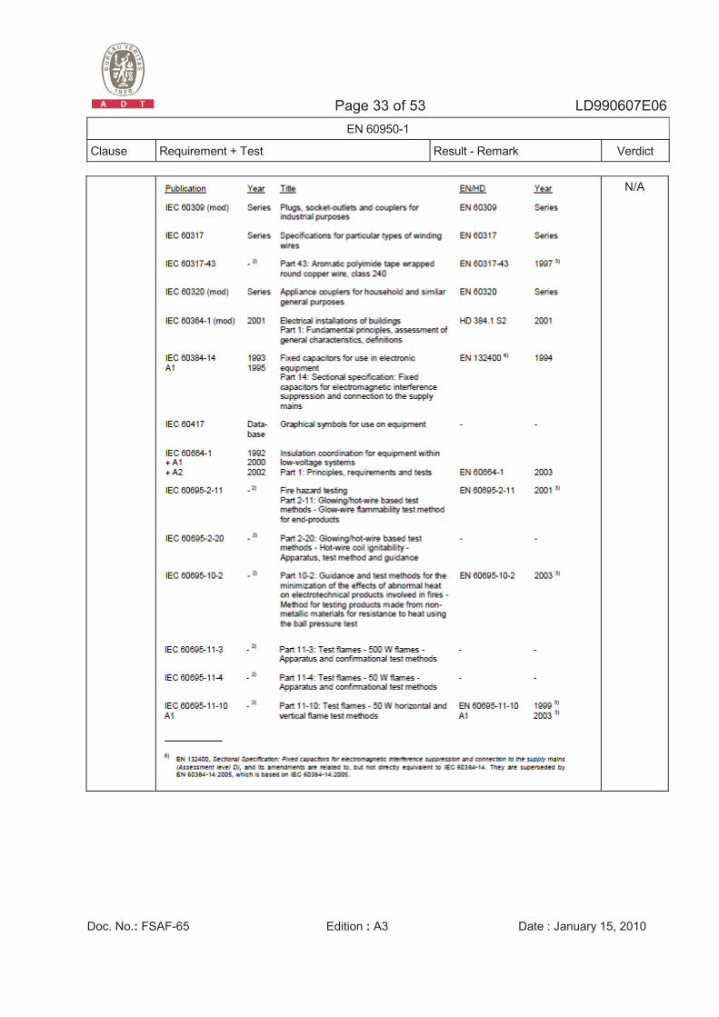
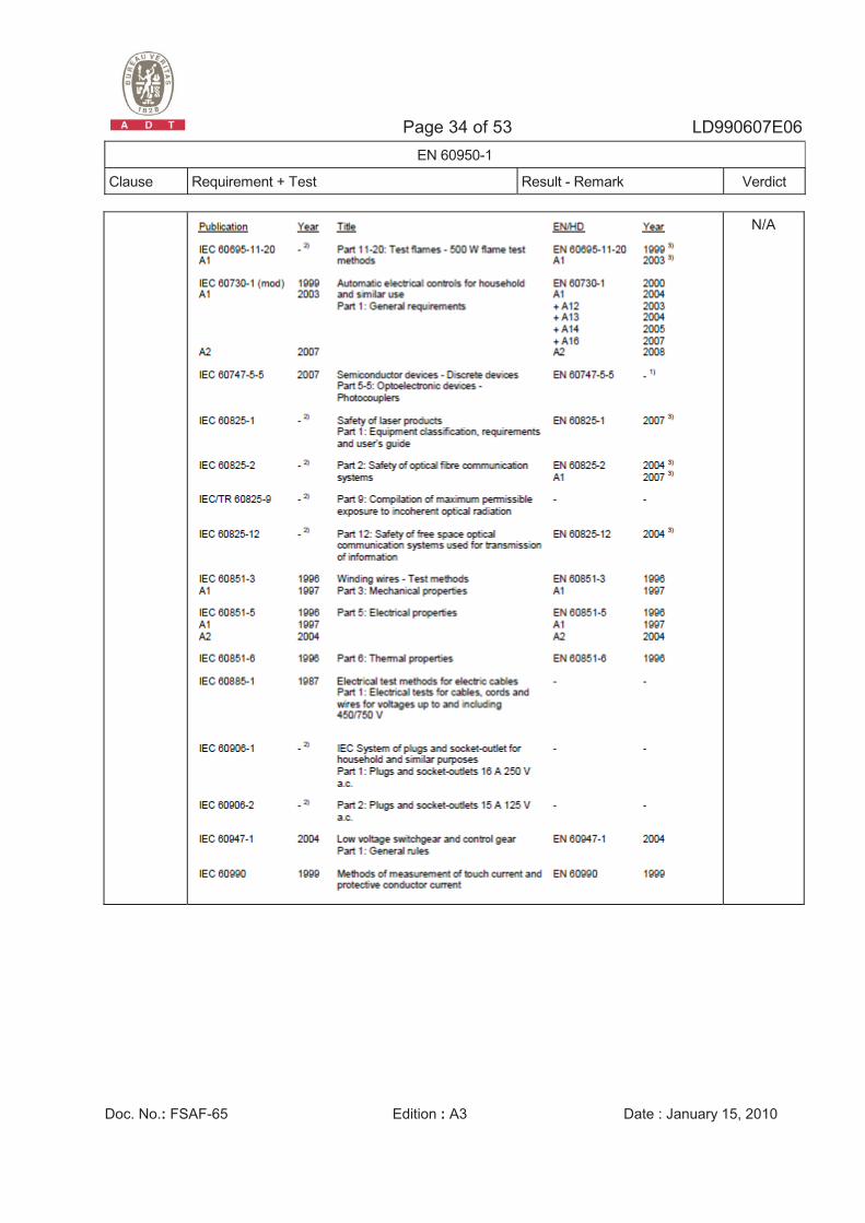
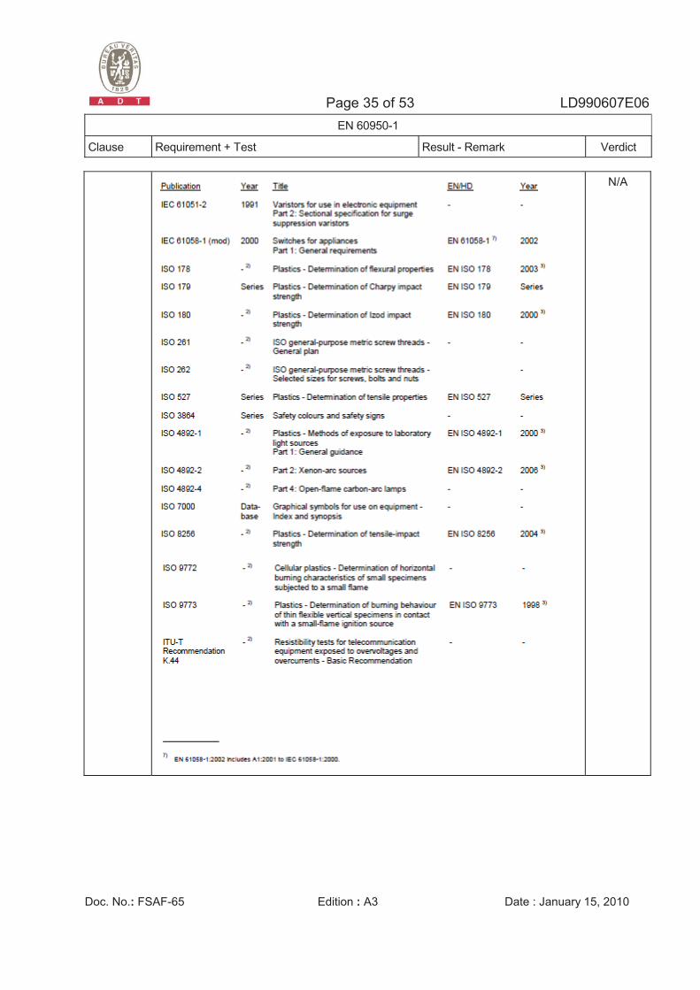
ZA NORMATIVE REFERENCES TO INTERNATIONAL PUBLICATIONS WITH THEIR CORRESPONDING EUROPEAN PUBLICATIONS
⎯
N/A
Page 33 of 53 LD990607E06 EN 60950-1
Clause Requirement + Test Result - Remark Verdict
Doc. No.: FSAF-65 Edition : A3 Date : January 15, 2010
N/A
Page 34 of 53 LD990607E06 EN 60950-1
Clause Requirement + Test Result - Remark Verdict
Doc. No.: FSAF-65 Edition : A3 Date : January 15, 2010
N/A
Page 35 of 53 LD990607E06 EN 60950-1
Clause Requirement + Test Result - Remark Verdict
Doc. No.: FSAF-65 Edition : A3 Date : January 15, 2010
N/A
Page 36 of 53 LD990607E06 EN 60950-1
Clause Requirement + Test Result - Remark Verdict
Doc. No.: FSAF-65 Edition : A3 Date : January 15, 2010
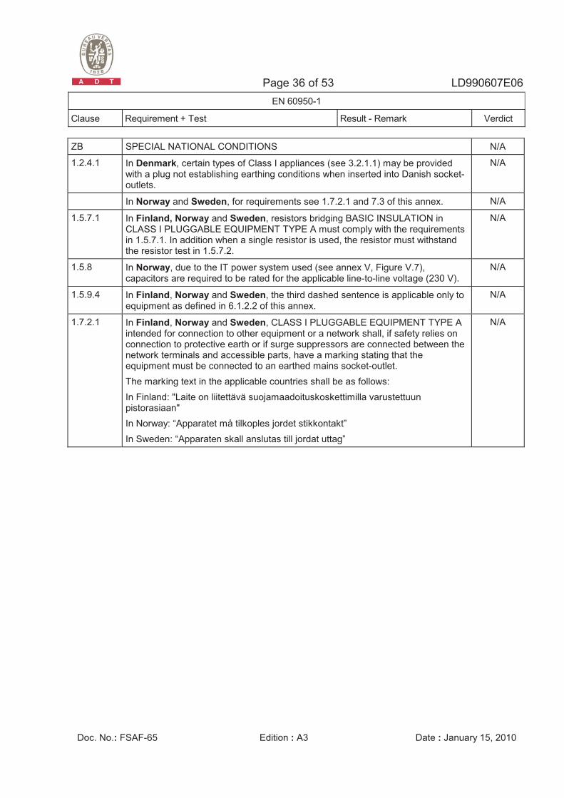
ZB SPECIAL NATIONAL CONDITIONS N/A
1.2.4.1 In Denmark, certain types of Class I appliances (see 3.2.1.1) may be provided with a plug not establishing earthing conditions when inserted into Danish socket-outlets.
N/A
In Norway and Sweden, for requirements see 1.7.2.1 and 7.3 of this annex. N/A
1.5.7.1 In Finland, Norway and Sweden, resistors bridging BASIC INSULATION in CLASS I PLUGGABLE EQUIPMENT TYPE A must comply with the requirements in 1.5.7.1. In addition when a single resistor is used, the resistor must withstand the resistor test in 1.5.7.2.
N/A
1.5.8 In Norway, due to the IT power system used (see annex V, Figure V.7), capacitors are required to be rated for the applicable line-to-line voltage (230 V).
N/A
1.5.9.4 In Finland, Norway and Sweden, the third dashed sentence is applicable only to equipment as defined in 6.1.2.2 of this annex.
N/A
1.7.2.1 In Finland, Norway and Sweden, CLASS I PLUGGABLE EQUIPMENT TYPE A intended for connection to other equipment or a network shall, if safety relies on connection to protective earth or if surge suppressors are connected between the network terminals and accessible parts, have a marking stating that the equipment must be connected to an earthed mains socket-outlet. The marking text in the applicable countries shall be as follows: In Finland: "Laite on liitettävä suojamaadoituskoskettimilla varustettuun pistorasiaan" In Norway: “Apparatet må tilkoples jordet stikkontakt” In Sweden: “Apparaten skall anslutas till jordat uttag”
N/A
Page 37 of 53 LD990607E06 EN 60950-1
Clause Requirement + Test Result - Remark Verdict
Doc. No.: FSAF-65 Edition : A3 Date : January 15, 2010
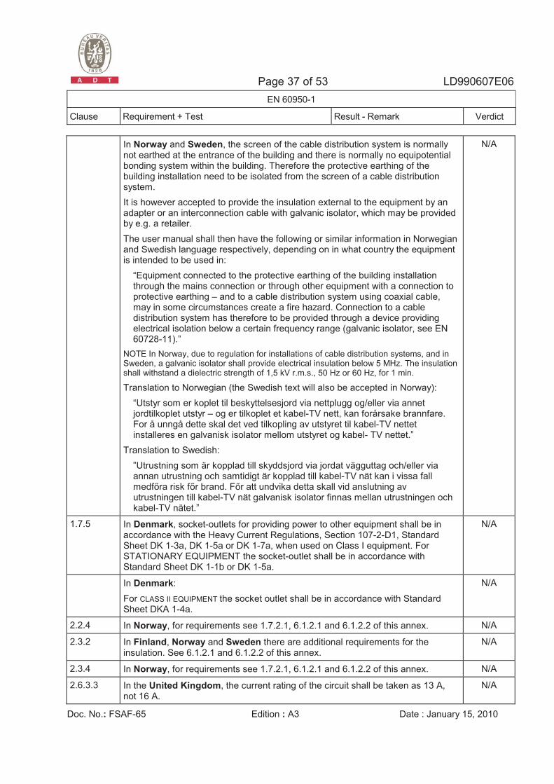
In Norway and Sweden, the screen of the cable distribution system is normally not earthed at the entrance of the building and there is normally no equipotential bonding system within the building. Therefore the protective earthing of the building installation need to be isolated from the screen of a cable distribution system. It is however accepted to provide the insulation external to the equipment by an adapter or an interconnection cable with galvanic isolator, which may be provided by e.g. a retailer. The user manual shall then have the following or similar information in Norwegian and Swedish language respectively, depending on in what country the equipment is intended to be used in:
“Equipment connected to the protective earthing of the building installation through the mains connection or through other equipment with a connection to protective earthing – and to a cable distribution system using coaxial cable, may in some circumstances create a fire hazard. Connection to a cable distribution system has therefore to be provided through a device providing electrical isolation below a certain frequency range (galvanic isolator, see EN 60728-11).”
NOTE In Norway, due to regulation for installations of cable distribution systems, and in Sweden, a galvanic isolator shall provide electrical insulation below 5 MHz. The insulation shall withstand a dielectric strength of 1,5 kV r.m.s., 50 Hz or 60 Hz, for 1 min.
Translation to Norwegian (the Swedish text will also be accepted in Norway): “Utstyr som er koplet til beskyttelsesjord via nettplugg og/eller via annet jordtilkoplet utstyr – og er tilkoplet et kabel-TV nett, kan forårsake brannfare. For å unngå dette skal det ved tilkopling av utstyret til kabel-TV nettet installeres en galvanisk isolator mellom utstyret og kabel- TV nettet.”
Translation to Swedish: ”Utrustning som är kopplad till skyddsjord via jordat vägguttag och/eller via annan utrustning och samtidigt är kopplad till kabel-TV nät kan i vissa fall medf�ra risk f�r brand. F�r att undvika detta skall vid anslutning av utrustningen till kabel-TV nät galvanisk isolator finnas mellan utrustningen och kabel-TV nätet.”
N/A
1.7.5 In Denmark, socket-outlets for providing power to other equipment shall be in accordance with the Heavy Current Regulations, Section 107-2-D1, Standard Sheet DK 1-3a, DK 1-5a or DK 1-7a, when used on Class I equipment. For STATIONARY EQUIPMENT the socket-outlet shall be in accordance with Standard Sheet DK 1-1b or DK 1-5a.
N/A
In Denmark: For CLASS II EQUIPMENT the socket outlet shall be in accordance with Standard Sheet DKA 1-4a.
N/A
2.2.4 In Norway, for requirements see 1.7.2.1, 6.1.2.1 and 6.1.2.2 of this annex. N/A
2.3.2 In Finland, Norway and Sweden there are additional requirements for the insulation. See 6.1.2.1 and 6.1.2.2 of this annex.
N/A
2.3.4 In Norway, for requirements see 1.7.2.1, 6.1.2.1 and 6.1.2.2 of this annex. N/A
2.6.3.3 In the United Kingdom, the current rating of the circuit shall be taken as 13 A, not 16 A.
N/A
Page 38 of 53 LD990607E06 EN 60950-1
Clause Requirement + Test Result - Remark Verdict
Doc. No.: FSAF-65 Edition : A3 Date : January 15, 2010
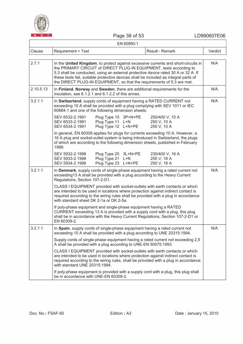
2.7.1 In the United Kingdom, to protect against excessive currents and short-circuits in the PRIMARY CIRCUIT of DIRECT PLUG-IN EQUIPMENT, tests according to 5.3 shall be conducted, using an external protective device rated 30 A or 32 A. If these tests fail, suitable protective devices shall be included as integral parts of the DIRECT PLUG-IN EQUIPMENT, so that the requirements of 5.3 are met.
N/A
2.10.5.13 In Finland, Norway and Sweden, there are additional requirements for the insulation, see 6.1.2.1 and 6.1.2.2 of this annex.
N/A
3.2.1.1 In Switzerland, supply cords of equipment having a RATED CURRENT not exceeding 10 A shall be provided with a plug complying with SEV 1011 or IEC 60884-1 and one of the following dimension sheets: SEV 6532-2.1991 Plug Type 15 3P+N+PE 250/400 V, 10 A SEV 6533-2.1991 Plug Type 11 L+N 250 V, 10 A SEV 6534-2.1991 Plug Type 12 L+N+PE 250 V, 10 A In general, EN 60309 applies for plugs for currents exceeding 10 A. However, a 16 A plug and socket-outlet system is being introduced in Switzerland, the plugs of which are according to the following dimension sheets, published in February 1998: SEV 5932-2.1998 Plug Type 25 3L+N+PE 230/400 V, 16 A SEV 5933-2.1998 Plug Type 21 L+N 250 V, 16 A SEV 5934-2.1998 Plug Type 23 L+N+PE 250 V, 16 A
N/A
3.2.1.1 In Denmark, supply cords of single-phase equipment having a rated current not exceeding13 A shall be provided with a plug according to the Heavy Current Regulations, Section 107-2-D1. CLASS I EQUIPMENT provided with socket-outlets with earth contacts or which are intended to be used in locations where protection against indirect contact is required according to the wiring rules shall be provided with a plug in accordance with standard sheet DK 2-1a or DK 2-5a. If poly-phase equipment and single-phase equipment having a RATED CURRENT exceeding 13 A is provided with a supply cord with a plug, this plug shall be in accordance with the Heavy Current Regulations, Section 107-2-D1 or EN 60309-2.
N/A
3.2.1.1 In Spain, supply cords of single-phase equipment having a rated current not exceeding 10 A shall be provided with a plug according to UNE 20315:1994. Supply cords of single-phase equipment having a rated current not exceeding 2,5 A shall be provided with a plug according to UNE-EN 50075:1993. CLASS I EQUIPMENT provided with socket-outlets with earth contacts or which are intended to be used in locations where protection against indirect contact is required according to the wiring rules, shall be provided with a plug in accordance with standard UNE 20315:1994. If poly-phase equipment is provided with a supply cord with a plug, this plug shall be in accordance with UNE-EN 60309-2.
N/A
Page 39 of 53 LD990607E06 EN 60950-1
Clause Requirement + Test Result - Remark Verdict
Doc. No.: FSAF-65 Edition : A3 Date : January 15, 2010
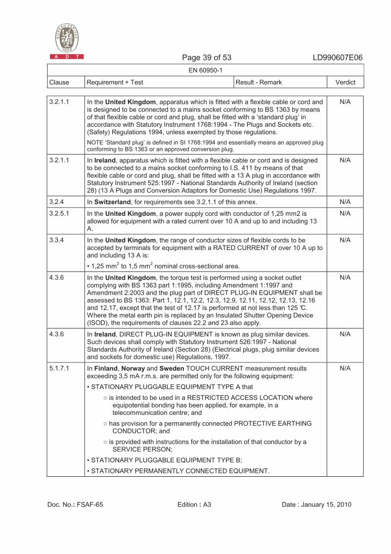
3.2.1.1 In the United Kingdom, apparatus which is fitted with a flexible cable or cord and is designed to be connected to a mains socket conforming to BS 1363 by means of that flexible cable or cord and plug, shall be fitted with a ‘standard plug’ in accordance with Statutory Instrument 1768:1994 - The Plugs and Sockets etc. (Safety) Regulations 1994, unless exempted by those regulations. NOTE ‘Standard plug’ is defined in SI 1768:1994 and essentially means an approved plug conforming to BS 1363 or an approved conversion plug.
N/A
3.2.1.1 In Ireland, apparatus which is fitted with a flexible cable or cord and is designed to be connected to a mains socket conforming to I.S. 411 by means of that flexible cable or cord and plug, shall be fitted with a 13 A plug in accordance with Statutory Instrument 525:1997 - National Standards Authority of Ireland (section 28) (13 A Plugs and Conversion Adaptors for Domestic Use) Regulations 1997.
N/A
3.2.4 In Switzerland, for requirements see 3.2.1.1 of this annex. N/A
3.2.5.1 In the United Kingdom, a power supply cord with conductor of 1,25 mm2 is allowed for equipment with a rated current over 10 A and up to and including 13 A.
N/A
3.3.4 In the United Kingdom, the range of conductor sizes of flexible cords to be accepted by terminals for equipment with a RATED CURRENT of over 10 A up to and including 13 A is: • 1,25 mm2 to 1,5 mm2 nominal cross-sectional area.
N/A
4.3.6 In the United Kingdom, the torque test is performed using a socket outlet complying with BS 1363 part 1:1995, including Amendment 1:1997 and Amendment 2:2003 and the plug part of DIRECT PLUG-IN EQUIPMENT shall be assessed to BS 1363: Part 1, 12.1, 12.2, 12.3, 12.9, 12.11, 12.12, 12.13, 12.16 and 12.17, except that the test of 12.17 is performed at not less than 125 °C. Where the metal earth pin is replaced by an Insulated Shutter Opening Device (ISOD), the requirements of clauses 22.2 and 23 also apply.
N/A
4.3.6 In Ireland, DIRECT PLUG-IN EQUIPMENT is known as plug similar devices. Such devices shall comply with Statutory Instrument 526:1997 - National Standards Authority of Ireland (Section 28) (Electrical plugs, plug similar devices and sockets for domestic use) Regulations, 1997.
N/A
5.1.7.1 In Finland, Norway and Sweden TOUCH CURRENT measurement results exceeding 3,5 mA r.m.s. are permitted only for the following equipment: • STATIONARY PLUGGABLE EQUIPMENT TYPE A that
� is intended to be used in a RESTRICTED ACCESS LOCATION where equipotential bonding has been applied, for example, in a telecommunication centre; and
� has provision for a permanently connected PROTECTIVE EARTHING CONDUCTOR; and
� is provided with instructions for the installation of that conductor by a SERVICE PERSON;
• STATIONARY PLUGGABLE EQUIPMENT TYPE B; • STATIONARY PERMANENTLY CONNECTED EQUIPMENT.
N/A
Page 40 of 53 LD990607E06 EN 60950-1
Clause Requirement + Test Result - Remark Verdict
Doc. No.: FSAF-65 Edition : A3 Date : January 15, 2010
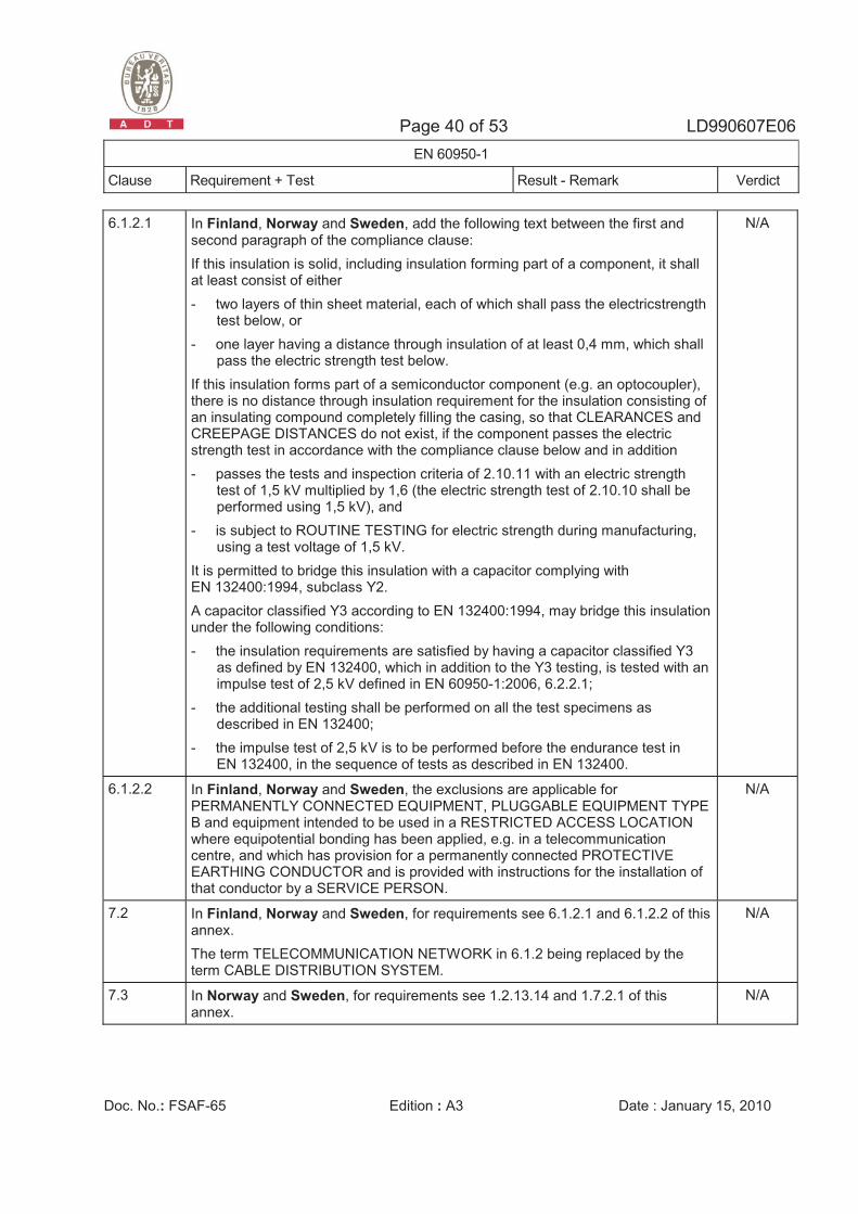
6.1.2.1 In Finland, Norway and Sweden, add the following text between the first and second paragraph of the compliance clause: If this insulation is solid, including insulation forming part of a component, it shall at least consist of either - two layers of thin sheet material, each of which shall pass the electricstrength
test below, or - one layer having a distance through insulation of at least 0,4 mm, which shall
pass the electric strength test below. If this insulation forms part of a semiconductor component (e.g. an optocoupler), there is no distance through insulation requirement for the insulation consisting of an insulating compound completely filling the casing, so that CLEARANCES and CREEPAGE DISTANCES do not exist, if the component passes the electric strength test in accordance with the compliance clause below and in addition - passes the tests and inspection criteria of 2.10.11 with an electric strength
test of 1,5 kV multiplied by 1,6 (the electric strength test of 2.10.10 shall be performed using 1,5 kV), and
- is subject to ROUTINE TESTING for electric strength during manufacturing, using a test voltage of 1,5 kV.
It is permitted to bridge this insulation with a capacitor complying with EN 132400:1994, subclass Y2. A capacitor classified Y3 according to EN 132400:1994, may bridge this insulation under the following conditions: - the insulation requirements are satisfied by having a capacitor classified Y3
as defined by EN 132400, which in addition to the Y3 testing, is tested with an impulse test of 2,5 kV defined in EN 60950-1:2006, 6.2.2.1;
- the additional testing shall be performed on all the test specimens as described in EN 132400;
- the impulse test of 2,5 kV is to be performed before the endurance test in EN 132400, in the sequence of tests as described in EN 132400.
N/A
6.1.2.2 In Finland, Norway and Sweden, the exclusions are applicable for PERMANENTLY CONNECTED EQUIPMENT, PLUGGABLE EQUIPMENT TYPE B and equipment intended to be used in a RESTRICTED ACCESS LOCATION where equipotential bonding has been applied, e.g. in a telecommunication centre, and which has provision for a permanently connected PROTECTIVE EARTHING CONDUCTOR and is provided with instructions for the installation of that conductor by a SERVICE PERSON.
N/A
7.2 In Finland, Norway and Sweden, for requirements see 6.1.2.1 and 6.1.2.2 of this annex. The term TELECOMMUNICATION NETWORK in 6.1.2 being replaced by the term CABLE DISTRIBUTION SYSTEM.
N/A
7.3 In Norway and Sweden, for requirements see 1.2.13.14 and 1.7.2.1 of this annex.
N/A
Page 41 of 53 LD990607E06 EN 60950-1
Clause Requirement + Test Result - Remark Verdict
Doc. No.: FSAF-65 Edition : A3 Date : January 15, 2010
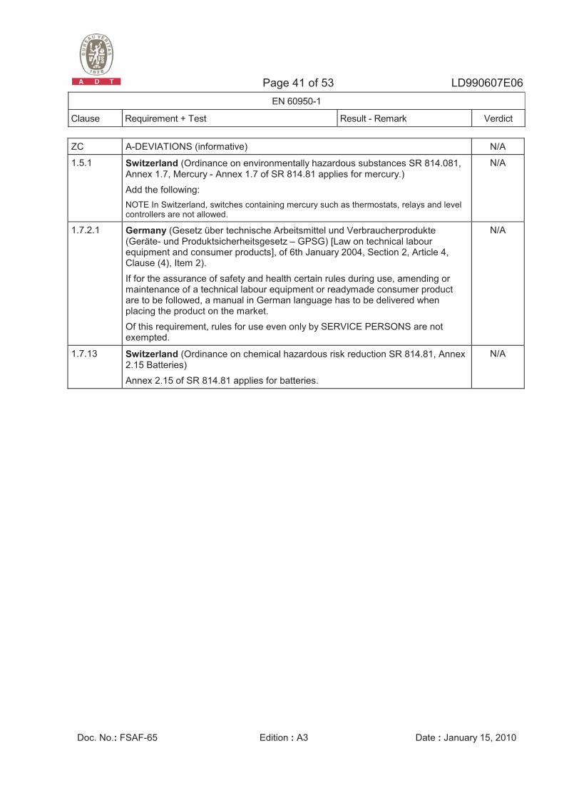
ZC A-DEVIATIONS (informative) N/A
1.5.1 Switzerland (Ordinance on environmentally hazardous substances SR 814.081, Annex 1.7, Mercury - Annex 1.7 of SR 814.81 applies for mercury.) Add the following: NOTE In Switzerland, switches containing mercury such as thermostats, relays and level controllers are not allowed.
N/A
1.7.2.1 Germany (Gesetz über technische Arbeitsmittel und Verbraucherprodukte (Geräte- und Produktsicherheitsgesetz – GPSG) [Law on technical labour equipment and consumer products], of 6th January 2004, Section 2, Article 4, Clause (4), Item 2). If for the assurance of safety and health certain rules during use, amending or maintenance of a technical labour equipment or readymade consumer product are to be followed, a manual in German language has to be delivered when placing the product on the market. Of this requirement, rules for use even only by SERVICE PERSONS are not exempted.
N/A
1.7.13 Switzerland (Ordinance on chemical hazardous risk reduction SR 814.81, Annex 2.15 Batteries) Annex 2.15 of SR 814.81 applies for batteries.
N/A
Page 42 of 53 LD990607E06 EN 60950-1
Clause Requirement + Test Result - Remark Verdict
Doc. No.: FSAF-65 Edition : A3 Date : January 15, 2010
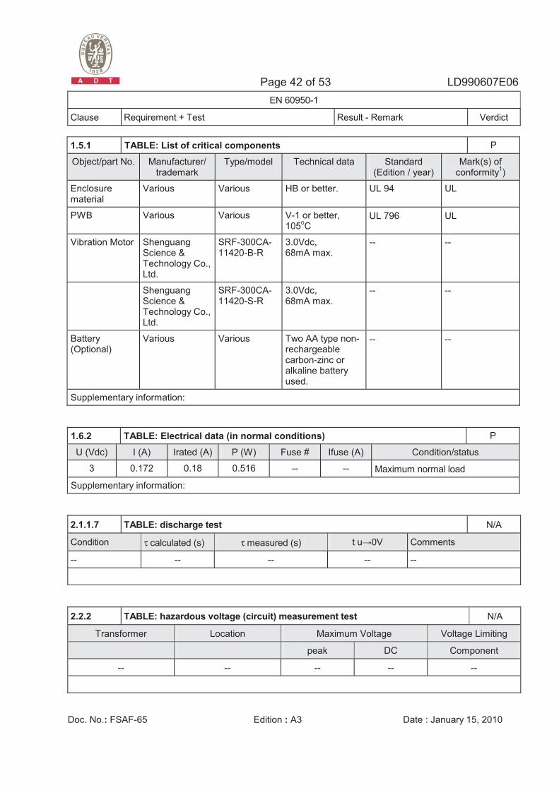
1.5.1 TABLE: List of critical components P
Object/part No. Manufacturer/ trademark
Type/model Technical data Standard (Edition / year)
Mark(s) of conformity1)
Enclosure material
Various Various HB or better. UL 94 UL
PWB Various Various V-1 or better, 105oC
UL 796 UL
Vibration Motor Shenguang Science & Technology Co., Ltd.
SRF-300CA-11420-B-R
3.0Vdc, 68mA max.
-- --
Shenguang Science & Technology Co., Ltd.
SRF-300CA-11420-S-R
3.0Vdc, 68mA max.
-- --
Battery (Optional)
Various Various Two AA type non-rechargeable carbon-zinc or alkaline battery used.
-- --
Supplementary information:
1.6.2 TABLE: Electrical data (in normal conditions) P
U (Vdc) I (A) Irated (A) P (W) Fuse # Ifuse (A) Condition/status
3 0.172 0.18 0.516 -- -- Maximum normal load
Supplementary information:
2.1.1.7 TABLE: discharge test N/A
Condition τ calculated (s) τ measured (s) t u�0V Comments
-- -- -- -- --
2.2.2 TABLE: hazardous voltage (circuit) measurement test N/A
Transformer Location Maximum Voltage Voltage Limiting
peak DC Component
-- -- -- -- --
Page 43 of 53 LD990607E06 EN 60950-1
Clause Requirement + Test Result - Remark Verdict
Doc. No.: FSAF-65 Edition : A3 Date : January 15, 2010
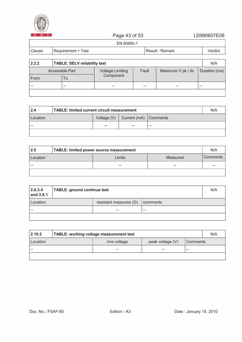
2.2.2 TABLE: SELV reliability test N/A
Accessible Part
From To
Voltage Limiting Component
Fault Maximum V pk / dc Duration (ms)
-- -- -- -- -- --
2.4 TABLE: limited current circuit measurement N/A
Location Voltage (V) Current (mA) Comments
-- -- -- --
2.5 TABLE: limited power source measurement N/A
Location Limits Measured Comments
-- -- -- --
2.6.3.4 and 2.6.1
TABLE: ground continue test N/A
Location resistant measures (�) comments
-- -- --
2.10.2 TABLE: working voltage measurement test N/A
Location rms voltage peak voltage (V) Comments
-- -- -- --
Page 44 of 53 LD990607E06 EN 60950-1
Clause Requirement + Test Result - Remark Verdict
Doc. No.: FSAF-65 Edition : A3 Date : January 15, 2010
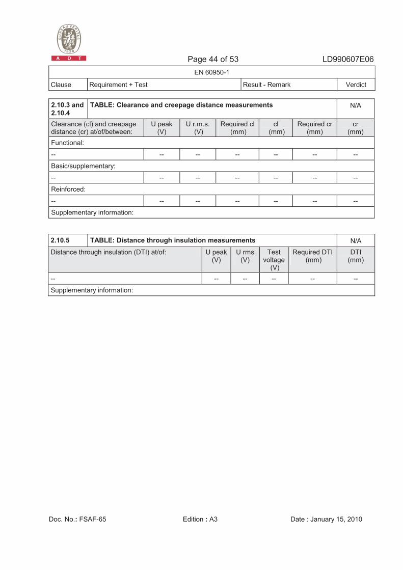
2.10.3 and 2.10.4
TABLE: Clearance and creepage distance measurements N/A
Clearance (cl) and creepage distance (cr) at/of/between:
U peak (V)
U r.m.s. (V)
Required cl (mm)
cl (mm)
Required cr (mm)
cr (mm)
Functional:
-- -- -- -- -- -- --
Basic/supplementary:
-- -- -- -- -- -- --
Reinforced:
-- -- -- -- -- -- --
Supplementary information:
2.10.5 TABLE: Distance through insulation measurements N/A
Distance through insulation (DTI) at/of: U peak(V)
U rms (V)
Test voltage
(V)
Required DTI (mm)
DTI (mm)
-- -- -- -- -- --
Supplementary information:
Page 45 of 53 LD990607E06 EN 60950-1
Clause Requirement + Test Result - Remark Verdict
Doc. No.: FSAF-65 Edition : A3 Date : January 15, 2010
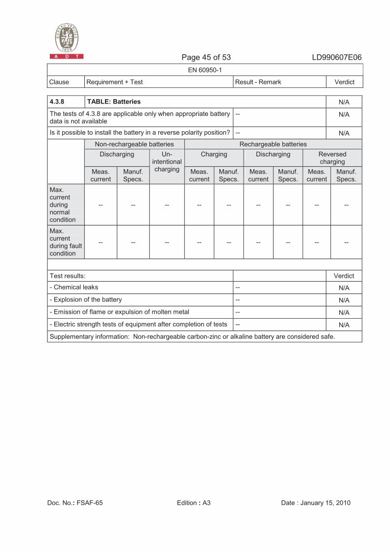
4.3.8 TABLE: Batteries N/A
The tests of 4.3.8 are applicable only when appropriate battery data is not available
-- N/A
Is it possible to install the battery in a reverse polarity position? -- N/A
Non-rechargeable batteries Rechargeable batteries Discharging Charging Discharging Reversed
charging Meas. current
Manuf. Specs.
Un-intentional charging Meas.
currentManuf. Specs.
Meas. current
Manuf. Specs.
Meas. current
Manuf. Specs.
Max. current during normal condition
-- -- -- -- -- -- -- -- --
Max. current during fault condition
-- -- -- -- -- -- -- -- --
Test results: Verdict
- Chemical leaks -- N/A
- Explosion of the battery -- N/A
- Emission of flame or expulsion of molten metal -- N/A
- Electric strength tests of equipment after completion of tests -- N/A
Supplementary information: Non-rechargeable carbon-zinc or alkaline battery are considered safe.
Page 46 of 53 LD990607E06 EN 60950-1
Clause Requirement + Test Result - Remark Verdict
Doc. No.: FSAF-65 Edition : A3 Date : January 15, 2010
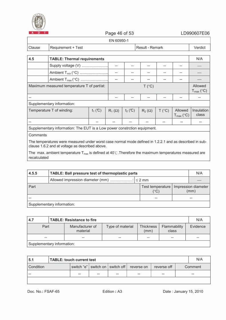
4.5 TABLE: Thermal requirements N/A
Supply voltage (V) ......................... -- -- -- -- -- ⎯
Ambient Tmin (°C) ........................... -- -- -- -- -- ⎯
Ambient Tmax (°C) .......................... -- -- -- -- -- ⎯
Maximum measured temperature T of part/at: T (°C) Allowed Tmax (°C)
-- -- -- -- -- -- --
Supplementary information:
Temperature T of winding: t1 (°C) R1 (Ω) t2 (°C) R2 (Ω) T (°C) Allowed Tmax (°C)
Insulation class
-- -- -- -- -- -- -- --
Supplementary information: The EUT is a Low power constrction equipment.
Comments
The temperatures were measured under worst case normal mode defined in 1.2.2.1 and as described in sub-clause 1.6.2 and at voltage as described above.
The max. ambient temperature Tmax is defined at 40�.Therefore the maximum temperatures measured are recalculated
4.5.5 TABLE: Ball pressure test of thermoplastic parts N/A
Allowed impression diameter (mm) .....................: ≤ 2 mm ⎯
Part Test temperature (°C)
Impression diameter (mm)
-- -- --
Supplementary information:
4.7 TABLE: Resistance to fire N/A
Part Manufacturer of material
Type of material Thickness (mm)
Flammabilityclass
Evidence
-- -- -- -- -- --
Supplementary information:
5.1 TABLE: touch current test N/A
Condition switch “e” switch on switch off reverse on reverse off Comment
-- -- -- -- -- -- --
Page 47 of 53 LD990607E06 EN 60950-1
Clause Requirement + Test Result - Remark Verdict
Doc. No.: FSAF-65 Edition : A3 Date : January 15, 2010
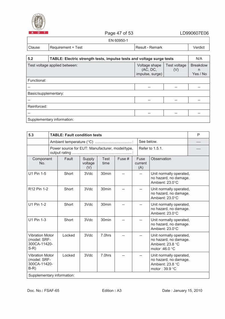
5.2 TABLE: Electric strength tests, impulse tests and voltage surge tests N/A
Test voltage applied between: Voltage shape(AC, DC,
impulse, surge)
Test voltage (V)
Breakdown
Yes / No
Functional:
-- -- -- --
Basic/supplementary:
-- -- -- --
Reinforced:
-- -- -- --
Supplementary information:
5.3 TABLE: Fault condition tests P
Ambient temperature (°C) ................................... : See below. ⎯
Power source for EUT: Manufacturer, model/type, output rating ......................................................... :
Refer to 1.5.1. ⎯
Component No.
Fault Supply voltage
(V)
Test time
Fuse # Fuse current
(A)
Observation
U1 Pin 1-5 Short 3Vdc 30min -- -- Unit normally operated, no hazard, no damage. Ambient: 23.0°C
R12 Pin 1-2 Short 3Vdc 30min -- -- Unit normally operated, no hazard, no damage. Ambient: 23.0°C
U1 Pin 1-2 Short 3Vdc 30min -- -- Unit normally operated, no hazard, no damage. Ambient: 23.0°C
U1 Pin 1-3 Short 3Vdc 30min -- -- Unit normally operated, no hazard, no damage. Ambient: 23.0°C
Vibration Motor (model: SRF-300CA-11420-S-R)
Locked 3Vdc 7.0hrs -- -- Unit normally operated, no hazard, no damage. Ambient: 23.8 °C motor :46.0 °C
Vibration Motor (model: SRF-300CA-11420-B-R)
Locked 3Vdc 7.0hrs -- -- Unit normally operated, no hazard, no damage. Ambient: 23.8 °C motor : 39.9 °C
Supplementary information:
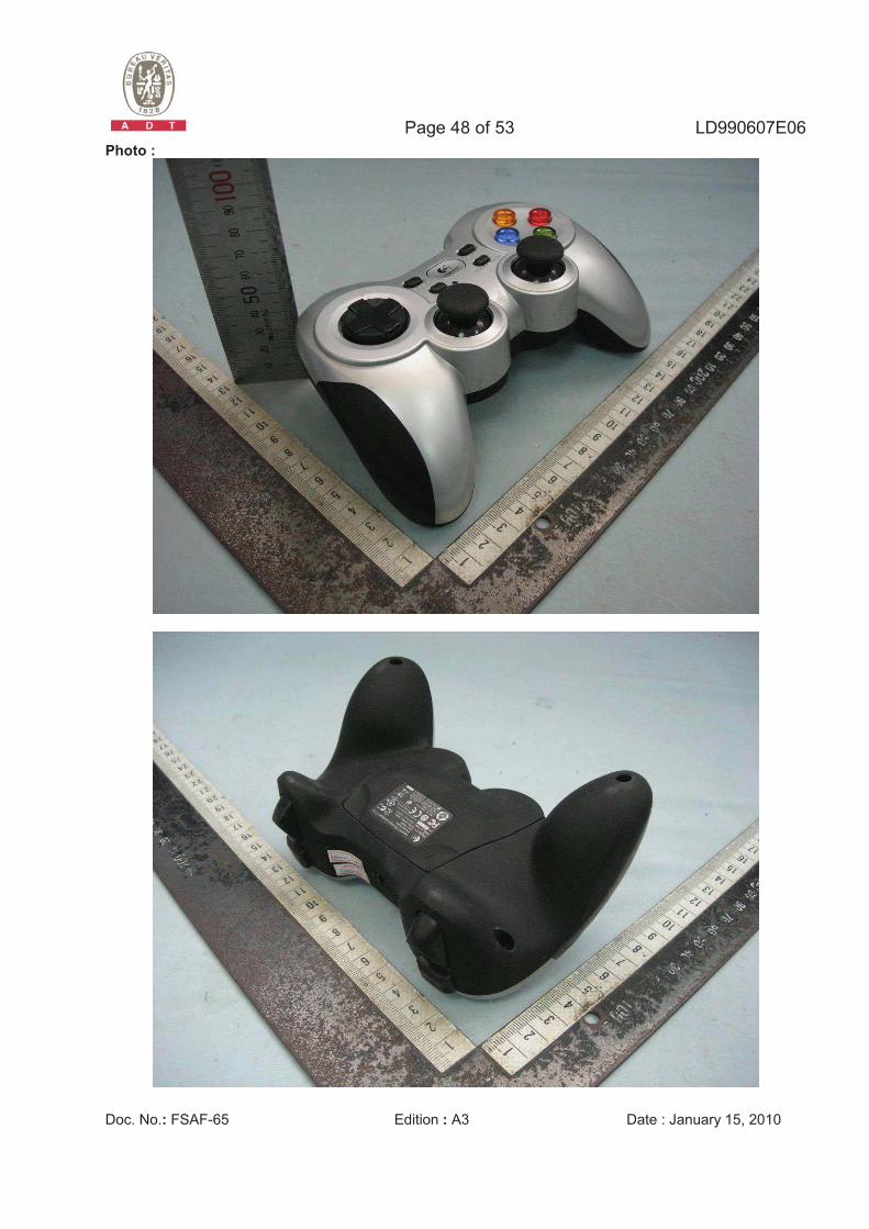
Page 48 of 53 LD990607E06
Doc. No.: FSAF-65 Edition : A3 Date : January 15, 2010
Photo :
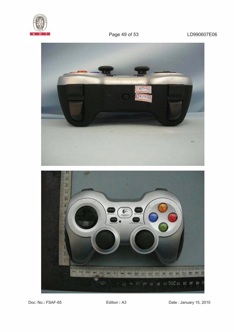
Page 49 of 53 LD990607E06
Doc. No.: FSAF-65 Edition : A3 Date : January 15, 2010
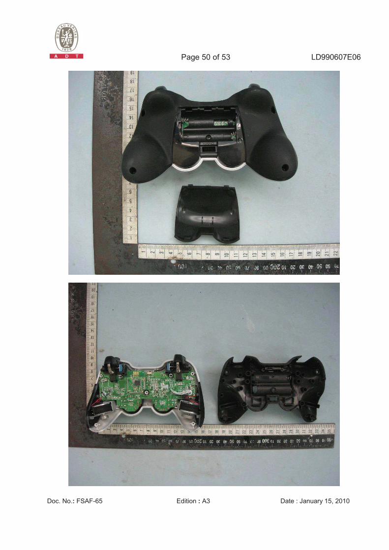
Page 50 of 53 LD990607E06
Doc. No.: FSAF-65 Edition : A3 Date : January 15, 2010
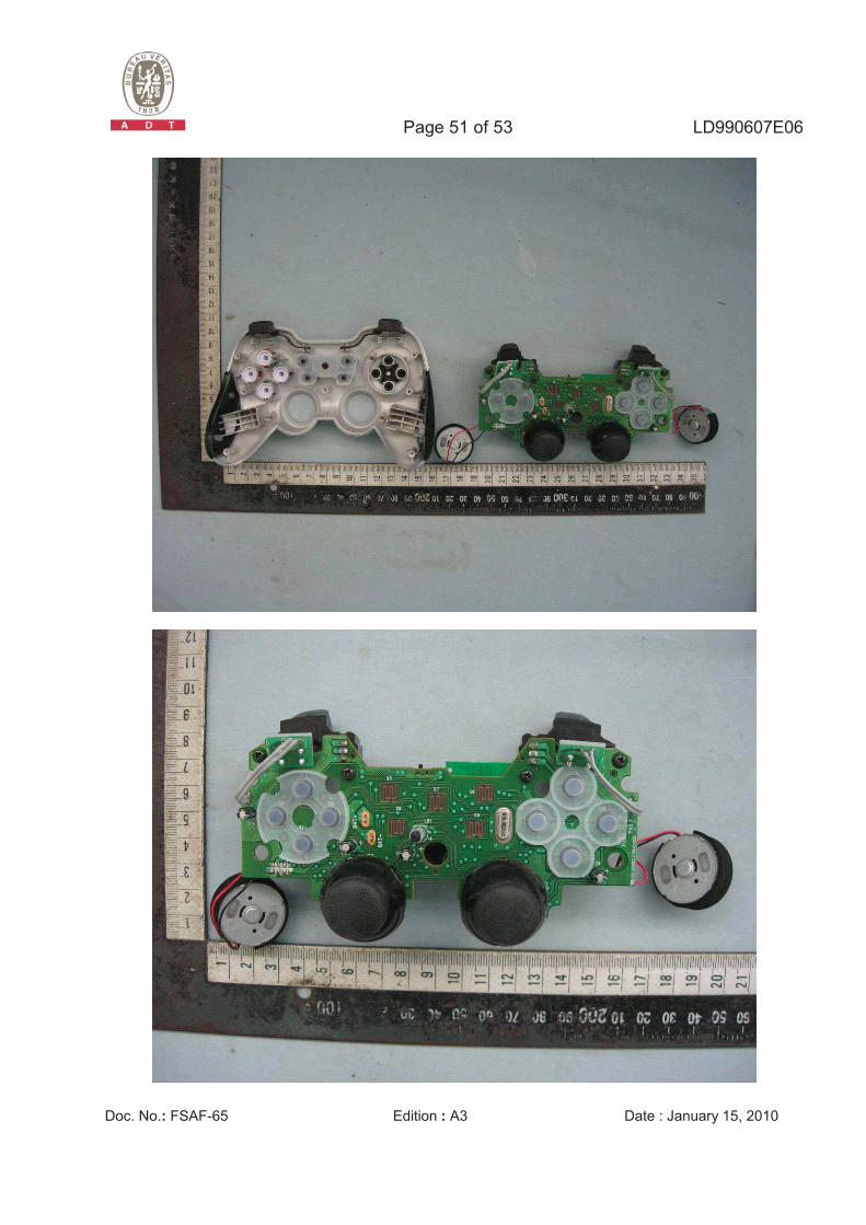
Page 51 of 53 LD990607E06
Doc. No.: FSAF-65 Edition : A3 Date : January 15, 2010
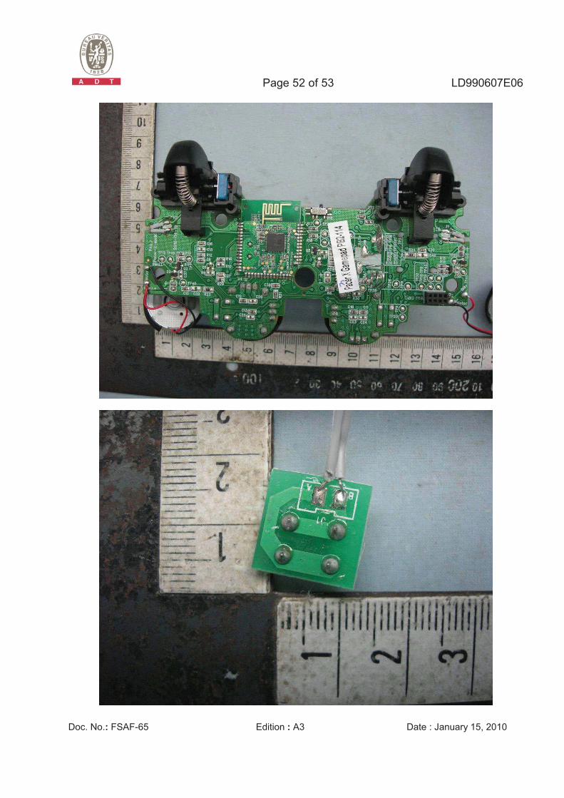
Page 52 of 53 LD990607E06
Doc. No.: FSAF-65 Edition : A3 Date : January 15, 2010
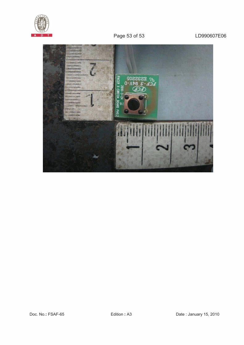
Page 53 of 53 LD990607E06
Doc. No.: FSAF-65 Edition : A3 Date : January 15, 2010