Embed Size (px)
Citation preview
Page 2 of 17 Report No.: SH11080399-009
Amendment 3: 4 April, 2015
TTRF EN ISO 11148_3A
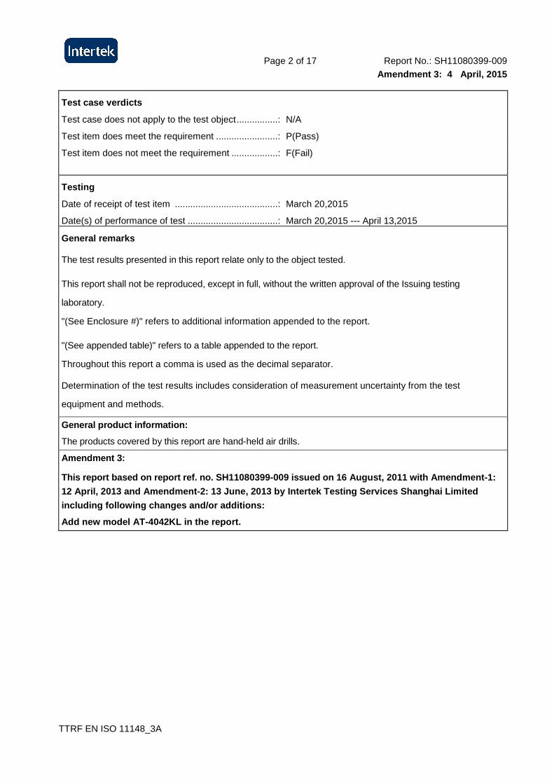
Test case verdicts
Test case does not apply to the test object ................ : N/A
Test item does meet the requirement ........................ : P(Pass)
Test item does not meet the requirement .................. : F(Fail)
Testing
Date of receipt of test item ........................................ : March 20,2015
Date(s) of performance of test ................................... : March 20,2015 --- April 13,2015
General remarks
The test results presented in this report relate only to the object tested.
This report shall not be reproduced, except in full, without the written approval of the Issuing testing
laboratory.
"(See Enclosure #)" refers to additional information appended to the report.
"(See appended table)" refers to a table appended to the report.
Throughout this report a comma is used as the decimal separator.
Determination of the test results includes consideration of measurement uncertainty from the test
equipment and methods.
General product information:
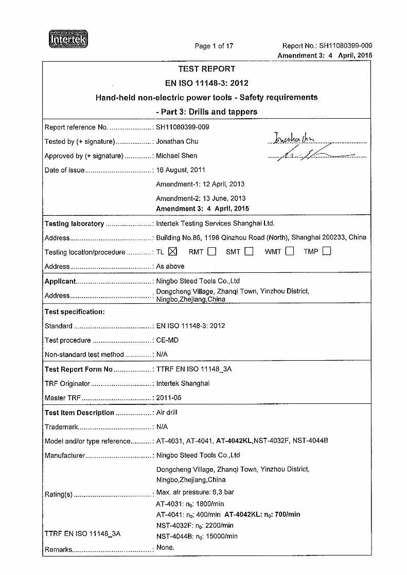
The products covered by this report are hand-held air drills.
Amendment 3:
This report based on report ref. no. SH11080399-009 issued on 16 August, 2011 with Amendment-1:
12 April, 2013 and Amendment-2: 13 June, 2013 by In tertek Testing Services Shanghai Limited
including following changes and/or additions:
Add new model AT-4042KL in the report.
Page 3 of 17 Report No.: SH11080399-009
Amendment 3: 4 April, 2015
TTRF EN ISO 11148_3A
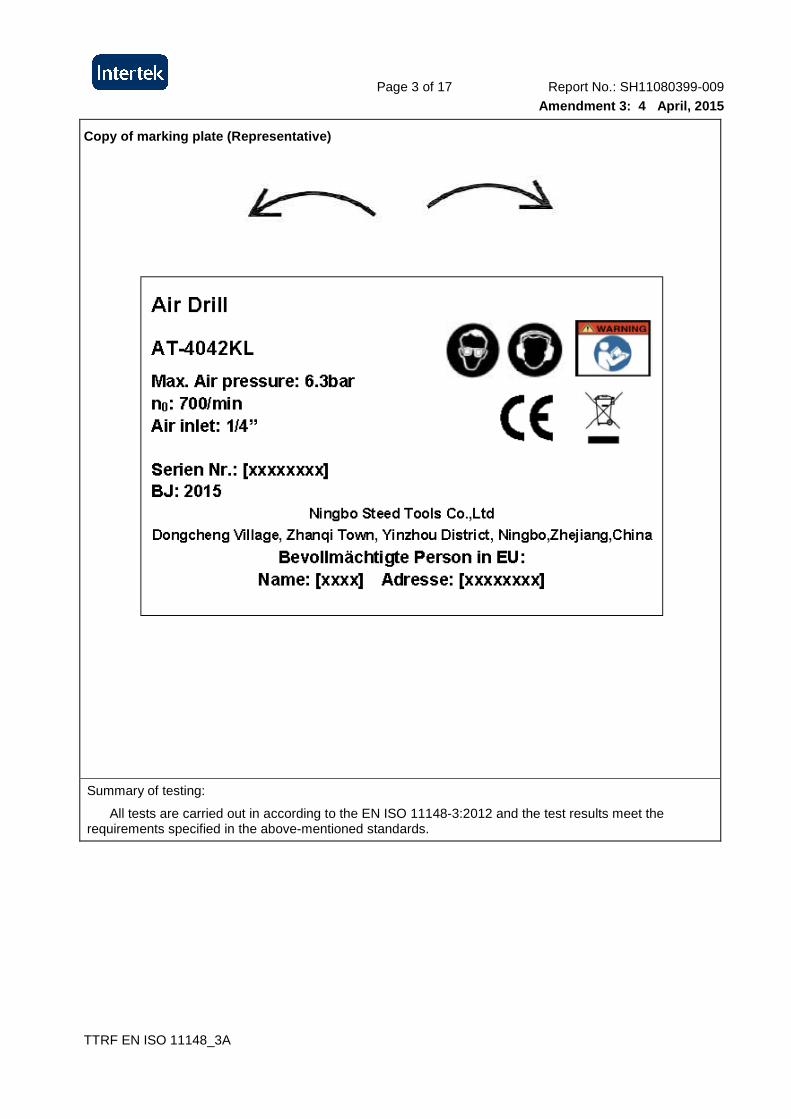
Copy of marking plate (Representative)
Summary of testing:
All tests are carried out in according to the EN ISO 11148-3:2012 and the test results meet the requirements specified in the above-mentioned standards.
Page 4 of 17 Report No.: SH11080399-009
Amendment 3: 4 April, 2015
EN ISO 11148-3:2012
Clause Requirement - Test Result - Remark Verdict
TTRF EN ISO 11148_3A
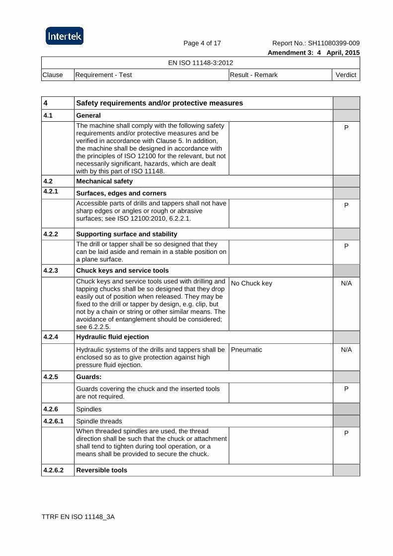
4 Safety requirements and/or protective measures
4.1 General
The machine shall comply with the following safety requirements and/or protective measures and be verified in accordance with Clause 5. In addition, the machine shall be designed in accordance with the principles of ISO 12100 for the relevant, but not necessarily significant, hazards, which are dealt with by this part of ISO 11148.
P
4.2 Mechanical safety
4.2.1 Surfaces, edges and corners
Accessible parts of drills and tappers shall not have sharp edges or angles or rough or abrasive surfaces; see ISO 12100:2010, 6.2.2.1.
P
4.2.2 Supporting surface and stability
The drill or tapper shall be so designed that they can be laid aside and remain in a stable position on a plane surface.
P
4.2.3 Chuck keys and service tools
Chuck keys and service tools used with drilling and tapping chucks shall be so designed that they drop easily out of position when released. They may be fixed to the drill or tapper by design, e.g. clip, but not by a chain or string or other similar means. The avoidance of entanglement should be considered; see 6.2.2.5.
No Chuck key N/A
4.2.4 Hydraulic fluid ejection
Hydraulic systems of the drills and tappers shall be enclosed so as to give protection against high pressure fluid ejection.
Pneumatic N/A
4.2.5 Guards:
Guards covering the chuck and the inserted tools are not required.
P
4.2.6 Spindles
4.2.6.1 Spindle threads
When threaded spindles are used, the thread direction shall be such that the chuck or attachment shall tend to tighten during tool operation, or a means shall be provided to secure the chuck.
P
4.2.6.2 Reversible tools
Page 5 of 17 Report No.: SH11080399-009
Amendment 3: 4 April, 2015
EN ISO 11148-3:2012
Clause Requirement - Test Result - Remark Verdict
TTRF EN ISO 11148_3A
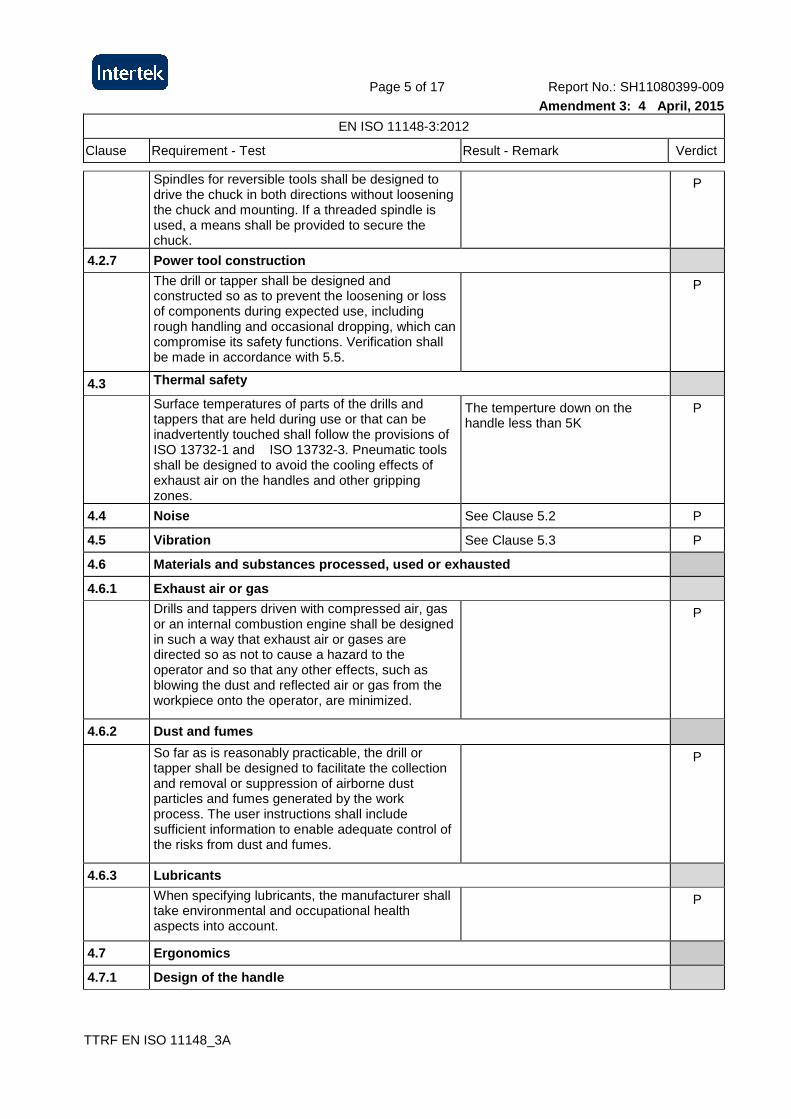
Spindles for reversible tools shall be designed to drive the chuck in both directions without loosening the chuck and mounting. If a threaded spindle is used, a means shall be provided to secure the chuck.
P
4.2.7 Power tool construction
The drill or tapper shall be designed and constructed so as to prevent the loosening or loss of components during expected use, including rough handling and occasional dropping, which can compromise its safety functions. Verification shall be made in accordance with 5.5.
P
4.3 Thermal safety
Surface temperatures of parts of the drills and tappers that are held during use or that can be inadvertently touched shall follow the provisions of ISO 13732-1 and ISO 13732-3. Pneumatic tools shall be designed to avoid the cooling effects of exhaust air on the handles and other gripping zones.
The temperture down on the handle less than 5K
P
4.4 Noise See Clause 5.2 P
4.5 Vibration See Clause 5.3 P
4.6 Materials and substances processed, used or exh austed
4.6.1 Exhaust air or gas
Drills and tappers driven with compressed air, gas or an internal combustion engine shall be designed in such a way that exhaust air or gases are directed so as not to cause a hazard to the operator and so that any other effects, such as blowing the dust and reflected air or gas from the workpiece onto the operator, are minimized.
P
4.6.2 Dust and fumes
So far as is reasonably practicable, the drill or tapper shall be designed to facilitate the collection and removal or suppression of airborne dust particles and fumes generated by the work process. The user instructions shall include sufficient information to enable adequate control of the risks from dust and fumes.
P
4.6.3 Lubricants
When specifying lubricants, the manufacturer shall take environmental and occupational health aspects into account.
P
4.7 Ergonomics
4.7.1 Design of the handle
Page 6 of 17 Report No.: SH11080399-009
Amendment 3: 4 April, 2015
EN ISO 11148-3:2012
Clause Requirement - Test Result - Remark Verdict
TTRF EN ISO 11148_3A
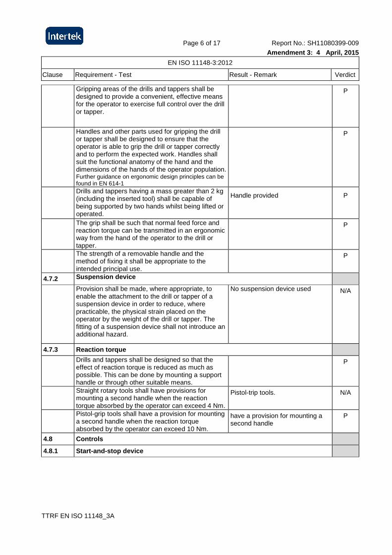
Gripping areas of the drills and tappers shall be designed to provide a convenient, effective means for the operator to exercise full control over the drill or tapper.
P
Handles and other parts used for gripping the drill or tapper shall be designed to ensure that the operator is able to grip the drill or tapper correctly and to perform the expected work. Handles shall suit the functional anatomy of the hand and the dimensions of the hands of the operator population. Further guidance on ergonomic design principles can be found in EN 614-1
P
Drills and tappers having a mass greater than 2 kg (including the inserted tool) shall be capable of being supported by two hands whilst being lifted or operated.
Handle provided P
The grip shall be such that normal feed force and reaction torque can be transmitted in an ergonomic way from the hand of the operator to the drill or tapper.
P
The strength of a removable handle and the method of fixing it shall be appropriate to the intended principal use.
P
4.7.2 Suspension device
Provision shall be made, where appropriate, to enable the attachment to the drill or tapper of a suspension device in order to reduce, where practicable, the physical strain placed on the operator by the weight of the drill or tapper. The fitting of a suspension device shall not introduce an additional hazard.
No suspension device used N/A
4.7.3 Reaction torque
Drills and tappers shall be designed so that the effect of reaction torque is reduced as much as possible. This can be done by mounting a support handle or through other suitable means.
P
Straight rotary tools shall have provisions for mounting a second handle when the reaction torque absorbed by the operator can exceed 4 Nm.
Pistol-trip tools. N/A
Pistol-grip tools shall have a provision for mounting a second handle when the reaction torque absorbed by the operator can exceed 10 Nm.
have a provision for mounting a second handle
P
4.8 Controls
4.8.1 Start-and-stop device
Page 7 of 17 Report No.: SH11080399-009
Amendment 3: 4 April, 2015
EN ISO 11148-3:2012
Clause Requirement - Test Result - Remark Verdict
TTRF EN ISO 11148_3A
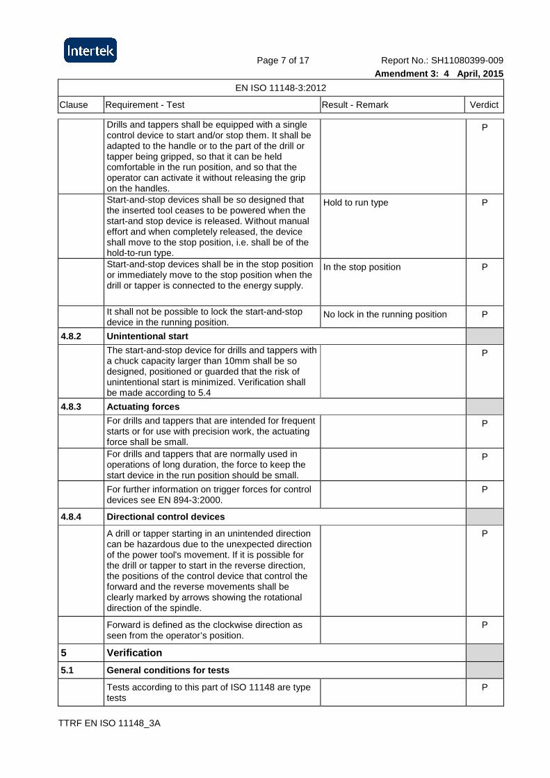
Drills and tappers shall be equipped with a single control device to start and/or stop them. It shall be adapted to the handle or to the part of the drill or tapper being gripped, so that it can be held comfortable in the run position, and so that the operator can activate it without releasing the grip on the handles.
P
Start-and-stop devices shall be so designed that the inserted tool ceases to be powered when the start-and stop device is released. Without manual effort and when completely released, the device shall move to the stop position, i.e. shall be of the hold-to-run type.
Hold to run type P
Start-and-stop devices shall be in the stop position or immediately move to the stop position when the drill or tapper is connected to the energy supply.
In the stop position P
It shall not be possible to lock the start-and-stop device in the running position.
No lock in the running position P
4.8.2 Unintentional start
The start-and-stop device for drills and tappers with a chuck capacity larger than 10mm shall be so designed, positioned or guarded that the risk of unintentional start is minimized. Verification shall be made according to 5.4
P
4.8.3 Actuating forces
For drills and tappers that are intended for frequent starts or for use with precision work, the actuating force shall be small.
P
For drills and tappers that are normally used in operations of long duration, the force to keep the start device in the run position should be small.
P
For further information on trigger forces for control devices see EN 894-3:2000.
P
4.8.4 Directional control devices
A drill or tapper starting in an unintended direction can be hazardous due to the unexpected direction of the power tool's movement. If it is possible for the drill or tapper to start in the reverse direction, the positions of the control device that control the forward and the reverse movements shall be clearly marked by arrows showing the rotational direction of the spindle.
P
Forward is defined as the clockwise direction as seen from the operator’s position.
P
5 Verification
5.1 General conditions for tests
Tests according to this part of ISO 11148 are type tests
P
Page 8 of 17 Report No.: SH11080399-009
Amendment 3: 4 April, 2015
EN ISO 11148-3:2012
Clause Requirement - Test Result - Remark Verdict
TTRF EN ISO 11148_3A
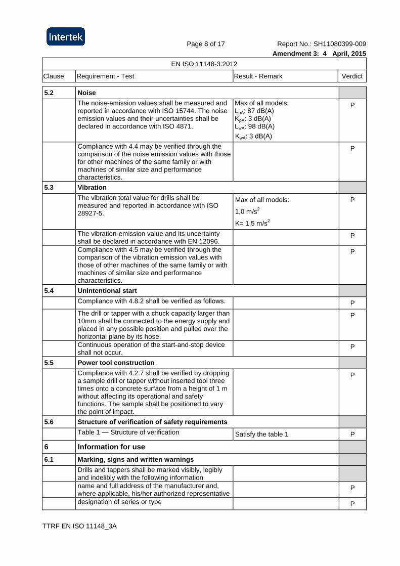
5.2 Noise
The noise-emission values shall be measured and reported in accordance with ISO 15744. The noise emission values and their uncertainties shall be declared in accordance with ISO 4871.
Max of all models: LpA: 87 dB(A) KpA: 3 dB(A) LwA: 98 dB(A)
KwA: 3 dB(A)
P
Compliance with 4.4 may be verified through the comparison of the noise emission values with those for other machines of the same family or with machines of similar size and performance characteristics.
P
5.3 Vibration
The vibration total value for drills shall be measured and reported in accordance with ISO 28927-5.
Max of all models:
1,0 m/s2
K= 1,5 m/s2
P
The vibration-emission value and its uncertainty shall be declared in accordance with EN 12096.
P
Compliance with 4.5 may be verified through the comparison of the vibration emission values with those of other machines of the same family or with machines of similar size and performance characteristics.
P
5.4 Unintentional start
Compliance with 4.8.2 shall be verified as follows. P
The drill or tapper with a chuck capacity larger than 10mm shall be connected to the energy supply and placed in any possible position and pulled over the horizontal plane by its hose.
P
Continuous operation of the start-and-stop device shall not occur.
P
5.5 Power tool construction
Compliance with 4.2.7 shall be verified by dropping a sample drill or tapper without inserted tool three times onto a concrete surface from a height of 1 m without affecting its operational and safety functions. The sample shall be positioned to vary the point of impact.
P
5.6 Structure of verification of safety requirement s
Table 1 — Structure of verification Satisfy the table 1 P
6 Information for use
6.1 Marking, signs and written warnings
Drills and tappers shall be marked visibly, legibly and indelibly with the following information
name and full address of the manufacturer and, where applicable, his/her authorized representative
P
designation of series or type P
Page 9 of 17 Report No.: SH11080399-009
Amendment 3: 4 April, 2015
EN ISO 11148-3:2012
Clause Requirement - Test Result - Remark Verdict
TTRF EN ISO 11148_3A
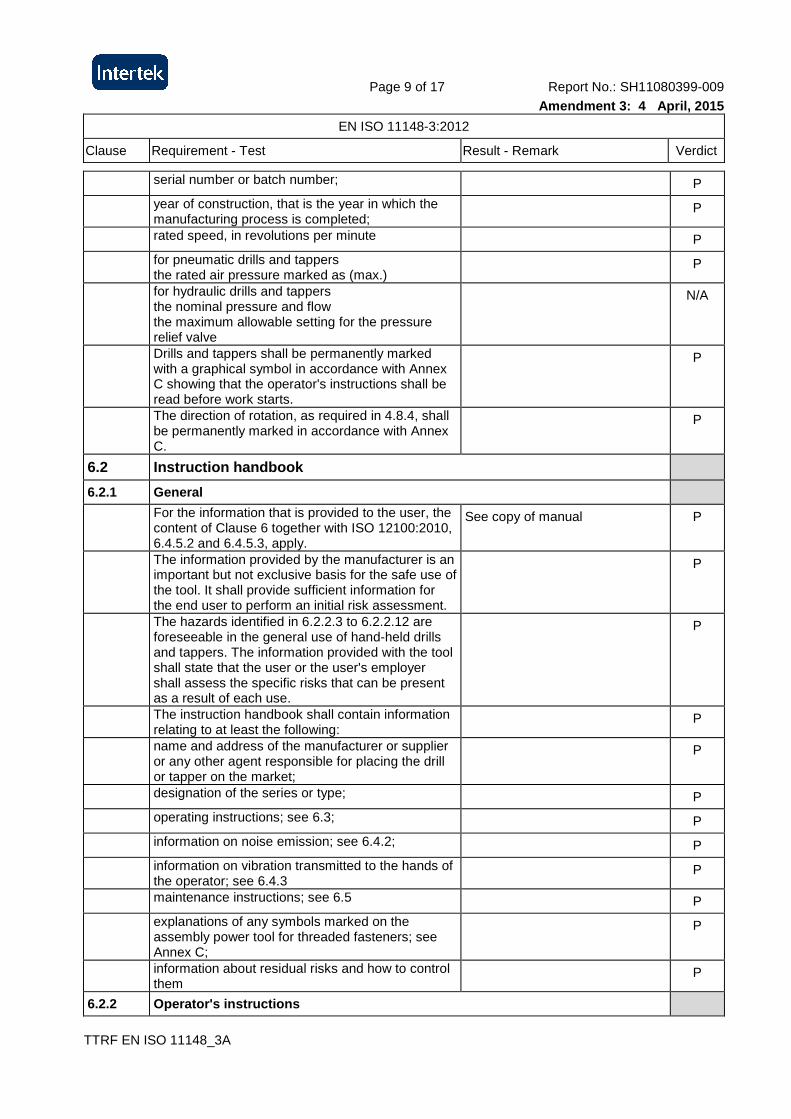
serial number or batch number; P
year of construction, that is the year in which the manufacturing process is completed;
P
rated speed, in revolutions per minute P
for pneumatic drills and tappers the rated air pressure marked as (max.)
P
for hydraulic drills and tappers the nominal pressure and flow the maximum allowable setting for the pressure relief valve
N/A
Drills and tappers shall be permanently marked with a graphical symbol in accordance with Annex C showing that the operator's instructions shall be read before work starts.
P
The direction of rotation, as required in 4.8.4, shall be permanently marked in accordance with Annex C.
P
6.2 Instruction handbook
6.2.1 General
For the information that is provided to the user, the content of Clause 6 together with ISO 12100:2010, 6.4.5.2 and 6.4.5.3, apply.
See copy of manual P
The information provided by the manufacturer is an important but not exclusive basis for the safe use of the tool. It shall provide sufficient information for the end user to perform an initial risk assessment.
P
The hazards identified in 6.2.2.3 to 6.2.2.12 are foreseeable in the general use of hand-held drills and tappers. The information provided with the tool shall state that the user or the user's employer shall assess the specific risks that can be present as a result of each use.
P
The instruction handbook shall contain information relating to at least the following:
P
name and address of the manufacturer or supplier or any other agent responsible for placing the drill or tapper on the market;
P
designation of the series or type; P
operating instructions; see 6.3; P
information on noise emission; see 6.4.2; P
information on vibration transmitted to the hands of the operator; see 6.4.3
P
maintenance instructions; see 6.5 P
explanations of any symbols marked on the assembly power tool for threaded fasteners; see Annex C;
P
information about residual risks and how to control them
P
6.2.2 Operator's instructions
Page 10 of 17 Report No.: SH11080399-009
Amendment 3: 4 April, 2015
EN ISO 11148-3:2012
Clause Requirement - Test Result - Remark Verdict
TTRF EN ISO 11148_3A
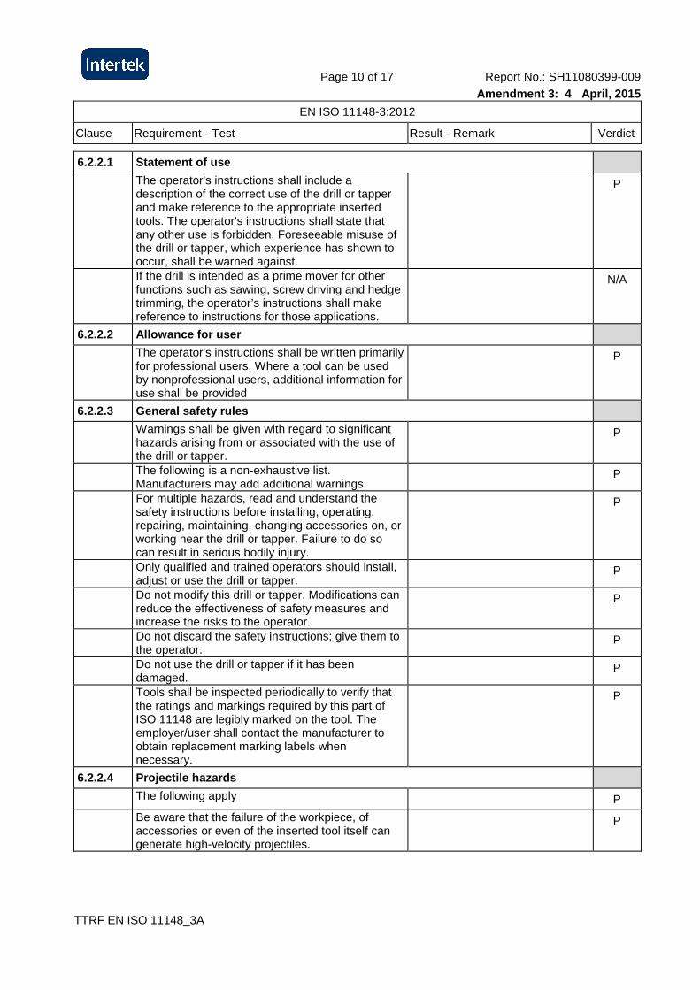
6.2.2.1 Statement of use
The operator's instructions shall include a description of the correct use of the drill or tapper and make reference to the appropriate inserted tools. The operator's instructions shall state that any other use is forbidden. Foreseeable misuse of the drill or tapper, which experience has shown to occur, shall be warned against.
P
If the drill is intended as a prime mover for other functions such as sawing, screw driving and hedge trimming, the operator’s instructions shall make reference to instructions for those applications.
N/A
6.2.2.2 Allowance for user
The operator's instructions shall be written primarily for professional users. Where a tool can be used by nonprofessional users, additional information for use shall be provided
P
6.2.2.3 General safety rules
Warnings shall be given with regard to significant hazards arising from or associated with the use of the drill or tapper.
P
The following is a non-exhaustive list. Manufacturers may add additional warnings.
P
For multiple hazards, read and understand the safety instructions before installing, operating, repairing, maintaining, changing accessories on, or working near the drill or tapper. Failure to do so can result in serious bodily injury.
P
Only qualified and trained operators should install, adjust or use the drill or tapper.
P
Do not modify this drill or tapper. Modifications can reduce the effectiveness of safety measures and increase the risks to the operator.
P
Do not discard the safety instructions; give them to the operator.
P
Do not use the drill or tapper if it has been damaged.
P
Tools shall be inspected periodically to verify that the ratings and markings required by this part of ISO 11148 are legibly marked on the tool. The employer/user shall contact the manufacturer to obtain replacement marking labels when necessary.
P
6.2.2.4 Projectile hazards
The following apply P
Be aware that the failure of the workpiece, of accessories or even of the inserted tool itself can generate high-velocity projectiles.
P
Page 11 of 17 Report No.: SH11080399-009
Amendment 3: 4 April, 2015
EN ISO 11148-3:2012
Clause Requirement - Test Result - Remark Verdict
TTRF EN ISO 11148_3A
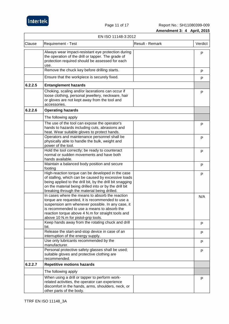
Always wear impact-resistant eye protection during the operation of the drill or tapper. The grade of protection required should be assessed for each use.
P
Remove the chuck key before drilling starts. P
Ensure that the workpiece is securely fixed. P
6.2.2.5 Entanglement hazards
Choking, scaling and/or lacerations can occur if loose clothing, personal jewellery, neckware, hair or gloves are not kept away from the tool and accessories.
P
6.2.2.6 Operating hazards
The following apply
The use of the tool can expose the operator's hands to hazards including cuts, abrasions and heat. Wear suitable gloves to protect hands.
P
Operators and maintenance personnel shall be physically able to handle the bulk, weight and power of the tool.
P
Hold the tool correctly; be ready to counteract normal or sudden movements and have both hands available.
P
Maintain a balanced body position and secure footing
P
High-reaction torque can be developed in the case of stalling, which can be caused by excessive loads being applied to the drill bit, by the drill bit snagging on the material being drilled into or by the drill bit breaking through the material being drilled.
P
In cases where the means to absorb the reaction torque are requested, it is recommended to use a suspension arm whenever possible. In any case, it is recommended to use a means to absorb the reaction torque above 4 N.m for straight tools and above 10 N.m for pistol-grip tools.
N/A
Keep hands away from the rotating chuck and drill bit.
P
Release the start-and-stop device in case of an interruption of the energy supply.
P
Use only lubricants recommended by the manufacturer.
P
Personal protective safety glasses shall be used; suitable gloves and protective clothing are recommended.
P
6.2.2.7 Repetitive motions hazards
The following apply
When using a drill or tapper to perform work-related activities, the operator can experience discomfort in the hands, arms, shoulders, neck, or other parts of the body.
P
Page 12 of 17 Report No.: SH11080399-009
Amendment 3: 4 April, 2015
EN ISO 11148-3:2012
Clause Requirement - Test Result - Remark Verdict
TTRF EN ISO 11148_3A
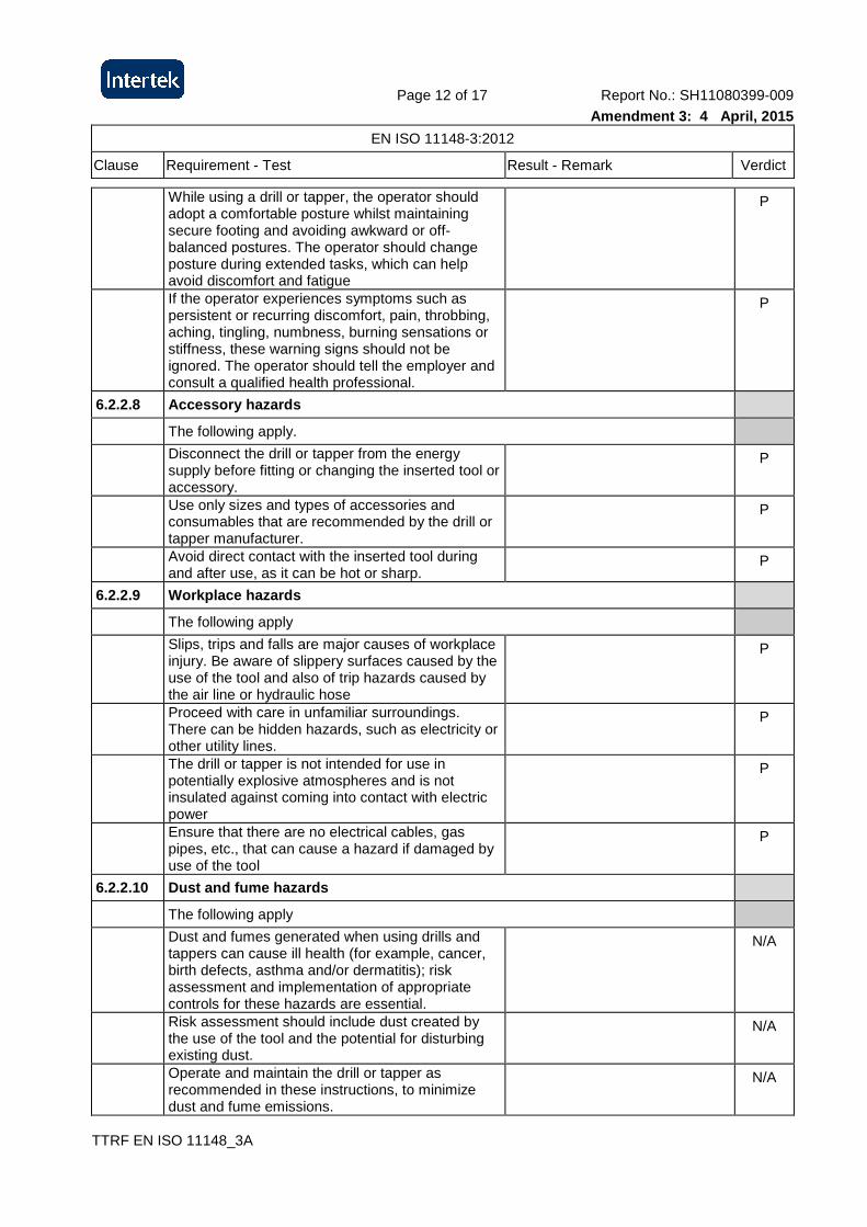
While using a drill or tapper, the operator should adopt a comfortable posture whilst maintaining secure footing and avoiding awkward or off-balanced postures. The operator should change posture during extended tasks, which can help avoid discomfort and fatigue
P
If the operator experiences symptoms such as persistent or recurring discomfort, pain, throbbing, aching, tingling, numbness, burning sensations or stiffness, these warning signs should not be ignored. The operator should tell the employer and consult a qualified health professional.
P
6.2.2.8 Accessory hazards
The following apply.
Disconnect the drill or tapper from the energy supply before fitting or changing the inserted tool or accessory.
P
Use only sizes and types of accessories and consumables that are recommended by the drill or tapper manufacturer.
P
Avoid direct contact with the inserted tool during and after use, as it can be hot or sharp.
P
6.2.2.9 Workplace hazards
The following apply
Slips, trips and falls are major causes of workplace injury. Be aware of slippery surfaces caused by the use of the tool and also of trip hazards caused by the air line or hydraulic hose
P
Proceed with care in unfamiliar surroundings. There can be hidden hazards, such as electricity or other utility lines.
P
The drill or tapper is not intended for use in potentially explosive atmospheres and is not insulated against coming into contact with electric power
P
Ensure that there are no electrical cables, gas pipes, etc., that can cause a hazard if damaged by use of the tool
P
6.2.2.10 Dust and fume hazards
The following apply
Dust and fumes generated when using drills and tappers can cause ill health (for example, cancer, birth defects, asthma and/or dermatitis); risk assessment and implementation of appropriate controls for these hazards are essential.
N/A
Risk assessment should include dust created by the use of the tool and the potential for disturbing existing dust.
N/A
Operate and maintain the drill or tapper as recommended in these instructions, to minimize dust and fume emissions.
N/A
Page 13 of 17 Report No.: SH11080399-009
Amendment 3: 4 April, 2015
EN ISO 11148-3:2012
Clause Requirement - Test Result - Remark Verdict
TTRF EN ISO 11148_3A
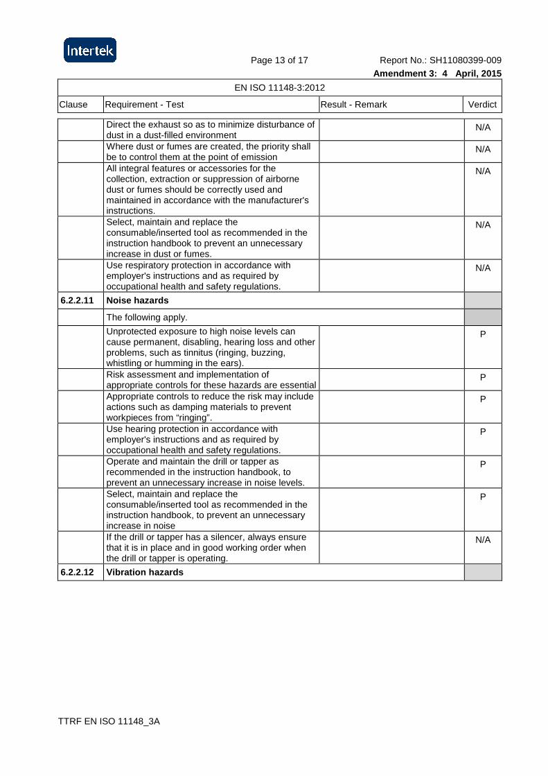
Direct the exhaust so as to minimize disturbance of dust in a dust-filled environment
N/A
Where dust or fumes are created, the priority shall be to control them at the point of emission
N/A
All integral features or accessories for the collection, extraction or suppression of airborne dust or fumes should be correctly used and maintained in accordance with the manufacturer's instructions.
N/A
Select, maintain and replace the consumable/inserted tool as recommended in the instruction handbook to prevent an unnecessary increase in dust or fumes.
N/A
Use respiratory protection in accordance with employer's instructions and as required by occupational health and safety regulations.
N/A
6.2.2.11 Noise hazards
The following apply.
Unprotected exposure to high noise levels can cause permanent, disabling, hearing loss and other problems, such as tinnitus (ringing, buzzing, whistling or humming in the ears).
P
Risk assessment and implementation of appropriate controls for these hazards are essential
P
Appropriate controls to reduce the risk may include actions such as damping materials to prevent workpieces from “ringing”.
P
Use hearing protection in accordance with employer's instructions and as required by occupational health and safety regulations.
P
Operate and maintain the drill or tapper as recommended in the instruction handbook, to prevent an unnecessary increase in noise levels.
P
Select, maintain and replace the consumable/inserted tool as recommended in the instruction handbook, to prevent an unnecessary increase in noise
P
If the drill or tapper has a silencer, always ensure that it is in place and in good working order when the drill or tapper is operating.
N/A
6.2.2.12 Vibration hazards
Page 14 of 17 Report No.: SH11080399-009
Amendment 3: 4 April, 2015
EN ISO 11148-3:2012
Clause Requirement - Test Result - Remark Verdict
TTRF EN ISO 11148_3A
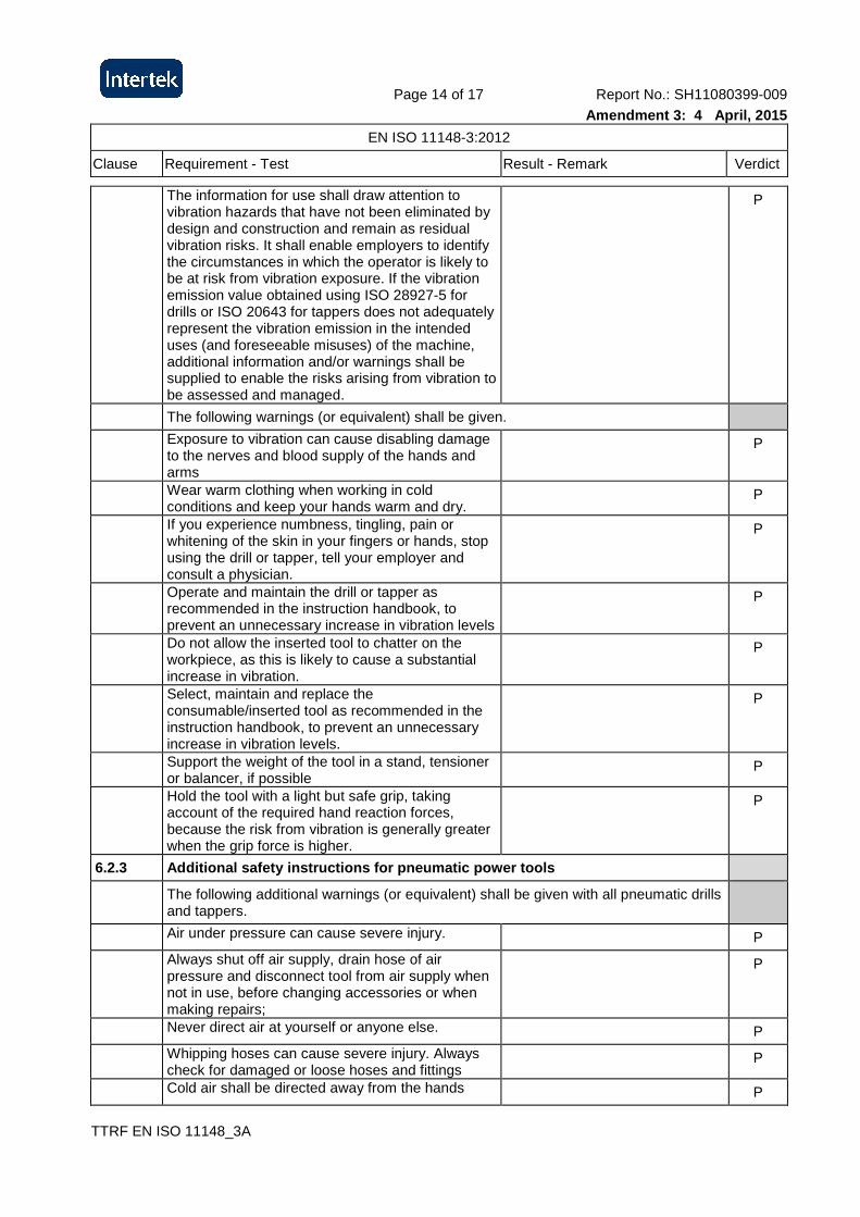
The information for use shall draw attention to vibration hazards that have not been eliminated by design and construction and remain as residual vibration risks. It shall enable employers to identify the circumstances in which the operator is likely to be at risk from vibration exposure. If the vibration emission value obtained using ISO 28927-5 for drills or ISO 20643 for tappers does not adequately represent the vibration emission in the intended uses (and foreseeable misuses) of the machine, additional information and/or warnings shall be supplied to enable the risks arising from vibration to be assessed and managed.
P
The following warnings (or equivalent) shall be given.
Exposure to vibration can cause disabling damage to the nerves and blood supply of the hands and arms
P
Wear warm clothing when working in cold conditions and keep your hands warm and dry.
P
If you experience numbness, tingling, pain or whitening of the skin in your fingers or hands, stop using the drill or tapper, tell your employer and consult a physician.
P
Operate and maintain the drill or tapper as recommended in the instruction handbook, to prevent an unnecessary increase in vibration levels
P
Do not allow the inserted tool to chatter on the workpiece, as this is likely to cause a substantial increase in vibration.
P
Select, maintain and replace the consumable/inserted tool as recommended in the instruction handbook, to prevent an unnecessary increase in vibration levels.
P
Support the weight of the tool in a stand, tensioner or balancer, if possible
P
Hold the tool with a light but safe grip, taking account of the required hand reaction forces, because the risk from vibration is generally greater when the grip force is higher.
P
6.2.3 Additional safety instructions for pneumatic power tools
The following additional warnings (or equivalent) shall be given with all pneumatic drills and tappers.
Air under pressure can cause severe injury. P
Always shut off air supply, drain hose of air pressure and disconnect tool from air supply when not in use, before changing accessories or when making repairs;
P
Never direct air at yourself or anyone else. P
Whipping hoses can cause severe injury. Always check for damaged or loose hoses and fittings
P
Cold air shall be directed away from the hands P
Page 15 of 17 Report No.: SH11080399-009
Amendment 3: 4 April, 2015
EN ISO 11148-3:2012
Clause Requirement - Test Result - Remark Verdict
TTRF EN ISO 11148_3A
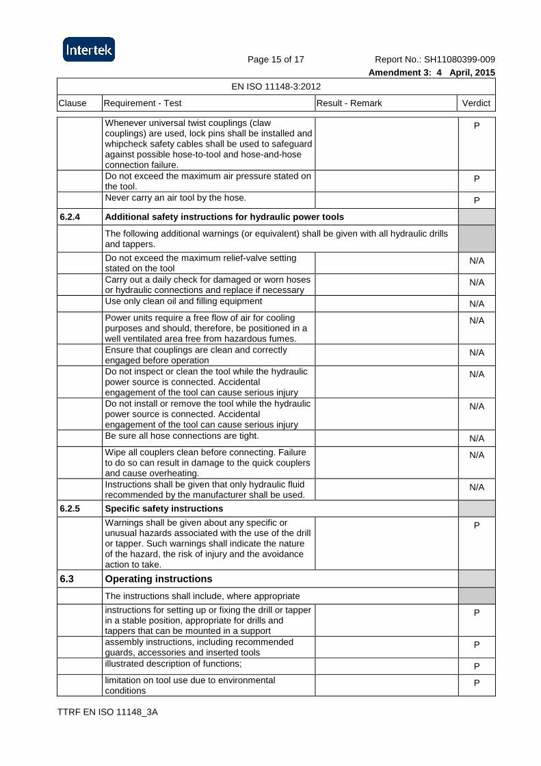
Whenever universal twist couplings (claw couplings) are used, lock pins shall be installed and whipcheck safety cables shall be used to safeguard against possible hose-to-tool and hose-and-hose connection failure.
P
Do not exceed the maximum air pressure stated on the tool.
P
Never carry an air tool by the hose. P
6.2.4 Additional safety instructions for hydraulic power tools
The following additional warnings (or equivalent) shall be given with all hydraulic drills and tappers.
Do not exceed the maximum relief-valve setting stated on the tool
N/A
Carry out a daily check for damaged or worn hoses or hydraulic connections and replace if necessary
N/A
Use only clean oil and filling equipment N/A
Power units require a free flow of air for cooling purposes and should, therefore, be positioned in a well ventilated area free from hazardous fumes.
N/A
Ensure that couplings are clean and correctly engaged before operation
N/A
Do not inspect or clean the tool while the hydraulic power source is connected. Accidental engagement of the tool can cause serious injury
N/A
Do not install or remove the tool while the hydraulic power source is connected. Accidental engagement of the tool can cause serious injury
N/A
Be sure all hose connections are tight. N/A
Wipe all couplers clean before connecting. Failure to do so can result in damage to the quick couplers and cause overheating.
N/A
Instructions shall be given that only hydraulic fluid recommended by the manufacturer shall be used.
N/A
6.2.5 Specific safety instructions
Warnings shall be given about any specific or unusual hazards associated with the use of the drill or tapper. Such warnings shall indicate the nature of the hazard, the risk of injury and the avoidance action to take.
P
6.3 Operating instructions
The instructions shall include, where appropriate
instructions for setting up or fixing the drill or tapper in a stable position, appropriate for drills and tappers that can be mounted in a support
P
assembly instructions, including recommended guards, accessories and inserted tools
P
illustrated description of functions; P
limitation on tool use due to environmental conditions
P
Page 16 of 17 Report No.: SH11080399-009
Amendment 3: 4 April, 2015
EN ISO 11148-3:2012
Clause Requirement - Test Result - Remark Verdict
TTRF EN ISO 11148_3A
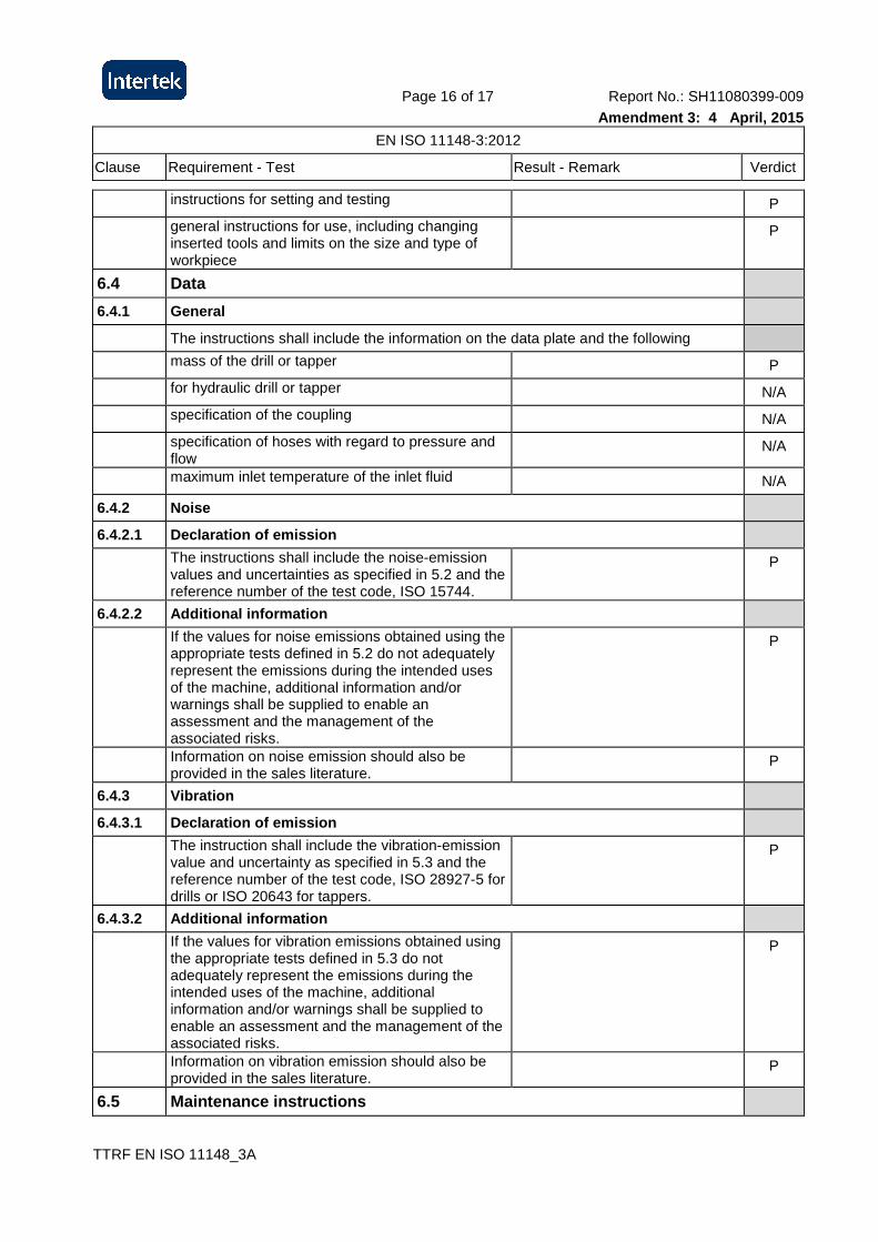
instructions for setting and testing P
general instructions for use, including changing inserted tools and limits on the size and type of workpiece
P
6.4 Data
6.4.1 General
The instructions shall include the information on the data plate and the following
mass of the drill or tapper P
for hydraulic drill or tapper N/A
specification of the coupling N/A
specification of hoses with regard to pressure and flow
N/A
maximum inlet temperature of the inlet fluid N/A
6.4.2 Noise
6.4.2.1 Declaration of emission
The instructions shall include the noise-emission values and uncertainties as specified in 5.2 and the reference number of the test code, ISO 15744.
P
6.4.2.2 Additional information
If the values for noise emissions obtained using the appropriate tests defined in 5.2 do not adequately represent the emissions during the intended uses of the machine, additional information and/or warnings shall be supplied to enable an assessment and the management of the associated risks.
P
Information on noise emission should also be provided in the sales literature.
P
6.4.3 Vibration
6.4.3.1 Declaration of emission
The instruction shall include the vibration-emission value and uncertainty as specified in 5.3 and the reference number of the test code, ISO 28927-5 for drills or ISO 20643 for tappers.
P
6.4.3.2 Additional information
If the values for vibration emissions obtained using the appropriate tests defined in 5.3 do not adequately represent the emissions during the intended uses of the machine, additional information and/or warnings shall be supplied to enable an assessment and the management of the associated risks.
P
Information on vibration emission should also be provided in the sales literature.
P
6.5 Maintenance instructions
Page 17 of 17 Report No.: SH11080399-009
Amendment 3: 4 April, 2015
EN ISO 11148-3:2012
Clause Requirement - Test Result - Remark Verdict
TTRF EN ISO 11148_3A
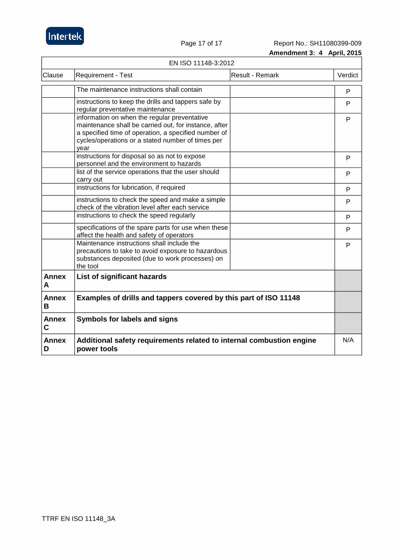
The maintenance instructions shall contain P
instructions to keep the drills and tappers safe by regular preventative maintenance
P
information on when the regular preventative maintenance shall be carried out, for instance, after a specified time of operation, a specified number of cycles/operations or a stated number of times per year
P
instructions for disposal so as not to expose personnel and the environment to hazards
P
list of the service operations that the user should carry out
P
instructions for lubrication, if required P
instructions to check the speed and make a simple check of the vibration level after each service
P
instructions to check the speed regularly P
specifications of the spare parts for use when these affect the health and safety of operators
P
Maintenance instructions shall include the precautions to take to avoid exposure to hazardous substances deposited (due to work processes) on the tool
P
Annex A
List of significant hazards
Annex B
Examples of drills and tappers covered by this part of ISO 11148
Annex C
Symbols for labels and signs
Annex D
Additional safety requirements related to internal combustion engine power tools
N/A