Embed Size (px)
Citation preview

Packaged Downflo® Evolution DFEP4 through DFEP8
Installation, Operation and Maintenance Manual
IOM AG8354401 (ENG)Revision 1
English Master Language
This manual contains specific precautions related to worker safety. The hazard alert image denotes safety related instructions and warnings in this manual. DO NOT operate or perform maintenance on this collector until you have read and understood the instruction and warnings contained within this manual.

Donaldson Company, Inc.
i
This manual has been supplied to assist with the installation, operation and maintenance for the collector purchased. Please read the manual before installing, operating, or performing maintenance on the collector as it contains specific precautions for worker safety. It is the owner’s responsibility to ensure that this manual is available for use by installers, operators and maintenance personnel that will be working with this collector. This manual is the property of the owner and should be left with the collector when installation has been completed. DO NOT operate this collector until you have read and understood the instructions and warnings located in this manual.For additional copies of this manual, contact Donaldson Torit.
The Safety Alert Symbol indicates a hazardous situation which, if not avoided could result in death or serious injury. Obey all safety messages following this symbol to avoid possible injury or death. The possible hazards are explained in the associated text messages.
Notice indicates a potential situation or practice which is not expected to result in personal injury, but which if not avoided may result in damage to equipment.
IMPORTANT NOTES

Packaged Downflo Evolution, DFEP4 through DFEP8
ii
Contents IMPORTANT NOTES ........................................................................................................................................................................ i 1 Safety Communication ..............................................................................................................................................................1 2 Product Description ...................................................................................................................................................................2
Standard Equipment ...........................................................................................................................................................3Inlet ..............................................................................................................................................................................3Filters ...........................................................................................................................................................................3Delta P Control ............................................................................................................................................................3Top Mounted Junction Box ..........................................................................................................................................4Dust Bin .......................................................................................................................................................................4Fan and Motor .............................................................................................................................................................4Airflow Control Damper ...............................................................................................................................................4Compressed Air Connection ........................................................................................................................................4Sprinkler Coupling .......................................................................................................................................................4
Collector Options ................................................................................................................................................................5Delta P Plus Control ....................................................................................................................................................5Extended Capacity Dust Bin (Standard on DFEP8) ....................................................................................................5
Accessories ........................................................................................................................................................................5Afterfilters ....................................................................................................................................................................5Explosion Relief Panels ...............................................................................................................................................5Remote Mounted Controls ..........................................................................................................................................5
3 Operation ...................................................................................................................................................................................6DFEP Operation Checklist ..................................................................................................................................................7
4 Product Service .........................................................................................................................................................................8Dust Bin Service .................................................................................................................................................................8Filter Replacement .............................................................................................................................................................9Afterfilter Replacement .....................................................................................................................................................10Afterfilter Field Assembly (when applicable) .....................................................................................................................10Diaphragm Valve Repair ...................................................................................................................................................11Solenoid Valve Repair ......................................................................................................................................................11Filter Access Cover Assembly Replacement ....................................................................................................................12Venturi Replacement ........................................................................................................................................................12Yoke Replacement (Special tool required) .......................................................................................................................13Fan and Motor Replacement ............................................................................................................................................14Troubleshooting ................................................................................................................................................................16
Appendix A - Collector Installation ................................................................................................................................................. A1Collector Installation ........................................................................................................................................................ A2
Collector Location and Site Selection ....................................................................................................................... A2Delivery and Inspection ............................................................................................................................................ A2Provisional Anchor Bolt Recommendations ............................................................................................................. A3
Installation ....................................................................................................................................................................... A3Collector Connections .............................................................................................................................................. A3DFEP8 Front High Inlet Installation .......................................................................................................................... A5Initial Start-up / Commissioning ................................................................................................................................ A6
Decommissioning Collector ............................................................................................................................................. A7Collector Information ....................................................................................................................................................... A8Service Notes .................................................................................................................................................................. A8
Donaldson Industrial Air Filtration Warranty ................................................................................................................................ A10
Donaldson Company, Inc.
1
Improper operation of dust collectors and/or dust control systems may contribute to conditions in a work area or facility which could result in severe personal injury, and product or property damage. All dust collection equipment should be used only for its intended purpose and should be properly selected and sized for its intended use.Process owners have important responsibilities relating to identifying and addressing potential hazards in their processes. When the potential for handling combustible dust exists within a process the process owner should include combustion hazards in their risk management activities and should comply with applicable codes and standards related to combustible dust.Electrical installation must be performed by a qualified electrician.This equipment is not designed to support site ducts, piping, or electrical services. All ducts, piping, or electrical services must be adequately supported to prevent injury and/or property damage.Site selection must account for wind, seismic zone, and other load conditions.Equipment may reach peak sound pressure levels above 80 dB (A). Noise levels should be considered when selecting collector location.
Combustible Dust HazardsAmong other considerations, the current NFPA standards require owners whose processes involve potentially combustible materials to have a current Dust Hazard Analysis, which can serve as the foundation for their process hazard mitigation strategy. Mitigation may include but is not limited to:
• Prevention of all ignition sources from entering any dust collection equipment.• Selection and implementation of fire and explosion mitigation, suppression, and isolation strategies appropriate for the
risks in their process.• Development and use of work practices to maintain safe operating conditions, and to ensure combustible dust does not
accumulate within their plant or process equipment.Donaldson recommends process owners consult experts in combustion risks to ensure these responsibilities are met. Some processes may involve materials or processes which have inherent fire and explosion hazards. The process owner retains responsibility to comply with applicable codes and standards and to manage the risks associated with the process or materials. Donaldson is neither an expert nor a certified consultant in fire, spark, or explosion detection, suppression, or control. Donaldson does not provide engineering consulting services related to process or dust hazard analyses, or code and standard compliance.
Donaldson may provide referrals to consultants and/or suppliers of equipment or services related to the detection and/or mitigation of sparks, fires and/or explosions, but Donaldson does not assume responsibility for any such referrals, nor does Donaldson assume any liability for the fitness of a mitigation strategy or product for a particular installation or application. The process owner’s final selection of dust collection and risk mitigation strategies should be based on the outcome of a Dust Hazard / Process Hazard Analysis performed by the process owner. Although early engagement of a dust collector supplier can provide helpful insights on the availability and features of various products, process owners should consult with combustible dust experts and/or process safety experts before making actual product and mitigation strategy selections.
Donaldson recommends all industrial air filtration system designs be reviewed and approved by an expert consultant responsible for the integrity of the system design and compliance with applicable codes and standards. It is the process owner’s responsibility to understand risks in their process and mitigate those risks in accordance with all applicable laws, regulations and standards, including those published by the NFPA. Donaldson also recommends proper maintenance and housekeeping procedures and work practices be evaluated, developed, and followed to maintain any industrial air filtration products in safe operating condition.
Many factors beyond the control of Donaldson can affect the use and performance of Donaldson products in a particular application, including the conditions under which the product is used. Since these factors are uniquely within the user’s knowledge and control, it is essential the user evaluate the Donaldson products to determine whether the product is fit for the particular purpose and suitable for the user’s application.
1 Safety Communication

2
Packaged Downflo Evolution, DFEP4 through DFEP8
The Packaged Downflo® Evolution (DFEP) dust collector is a continuous-duty collector using cartridge-style filters to separate dust and fume from an air stream. The standard collector comes equipped with top inlet which allows an integrated fan to draw air from a connected duct into the collector producing a downward airflow pattern in the collector. This airflow pattern promotes long filter life and dust drop out into the collection hopper.
The collector design allows for continuous duty operations where cartridge filters can be pulse cleaned to restore their flow performance, on-line, in sequence, without interrupting the overall airflow being drawn into the collector by the integrated fan. The standard pulse cleaning controls can be upgraded to allow for ‘down-time’ cleaning when the airflow through the collector is shut off, potentially extending filter life and reducing overall operating costs.
The DFEP collector has been designed for fast and simple installation. For most situations, the collector is positioned and anchored in place. Plant power is wired to the top mounted junction box. Compressed air is supplied to the 1-inch, NPT side mounted, compressed air fitting. Ducting is easily attached to the inlet collar. With these steps complete, the collector is ready for operation.
The standard DFEP collector comes with a dust bin located at the base of the collector. This dust bin is on rollers and can be serviced without tools, which makes dust removal a simple task. An optional extended capacity bin for DFEP4 and DFEP6 (standard on DFEP 8 collector) can be selected as an alternate for situations where larger volumes of dust are expected.
The DFEP collector is available with a variety of inlet designs for specific duct sizes across the range of airflow available from the integrated fan to accommodate a range of performance conditions.
Several additional accessories are available for the DFEP including HEPA grade afterfilters.
Intended UseThe DFEP collector is intended for filtration of nuisance dust or fume. Typical applications include filtration of nuisance fume produced during laser cutting, plasma cutting, thermal spraying, welding, or abrasive blasting processes. Extremely fine, and non-fibrous dusts or fume are very well served by Ultra-Web® filters, the standard in DFEP collectors.
2 Product Description
3
Donaldson Company, Inc.
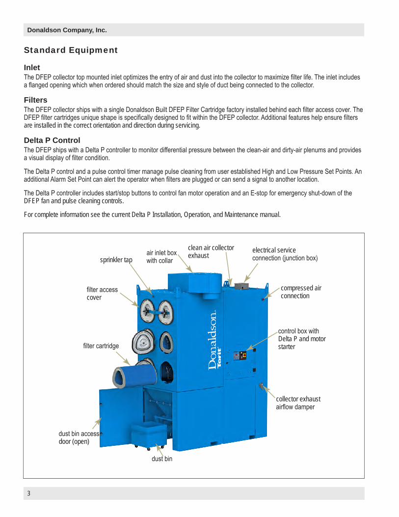
InletThe DFEP collector top mounted inlet optimizes the entry of air and dust into the collector to maximize filter life. The inlet includes a flanged opening which when ordered should match the size and style of duct being connected to the collector.
FiltersThe DFEP collector ships with a single Donaldson Built DFEP Filter Cartridge factory installed behind each filter access cover. The DFEP filter cartridges unique shape is specifically designed to fit within the DFEP collector. Additional features help ensure filters are installed in the correct orientation and direction during servicing.
Delta P ControlThe DFEP ships with a Delta P controller to monitor differential pressure between the clean-air and dirty-air plenums and provides a visual display of filter condition.
The Delta P control and a pulse control timer manage pulse cleaning from user established High and Low Pressure Set Points. An additional Alarm Set Point can alert the operator when filters are plugged or can send a signal to another location.
The Delta P controller includes start/stop buttons to control fan motor operation and an E-stop for emergency shut-down of the DFEP fan and pulse cleaning controls.
For complete information see the current Delta P Installation, Operation, and Maintenance manual.
Standard Equipment
air inlet box with collar
clean air collector exhaust
compressed air connection
control box with Delta P and motor starter
collector exhaust airflow damper
electrical service connection (junction box)
filter access cover
sprinkler tap
filter cartridge
dust bin access door (open)
dust bin
4
Packaged Downflo Evolution, DFEP4 through DFEP8
Top Mounted Junction BoxThe DFEP ships with internal wiring pre-wired at the factory (with the exception of explosion vented collectors). The top mounted junction box provides the terminal block interface between the internal wiring and the site-specific incoming wiring. Please refer to the wiring diagram print shipped within the internal electrical controller enclosure for wiring details.
Dust BinThe standard dust bin is located below the hopper to collect dust removed from the air stream. The dust bin is sealed to the hopper discharge with a convenient clamping arrangement which lifts the dust bin against a sealing gasket on the base of the hopper to ensure a dust tight seal during operation.
Fan and MotorAn internal factory installed fan and motor assembly produce airflow and external static pressure. The fan and motor assembly is located near the base of the collector to increase stability by lowering the collector's center of gravity. The fan/motor chamber is lined with acoustical foam and is designed in combination with the exhaust plenum to reduce average operational sound pressure levels below 80 dBa (at distances 1 meter from the DFEP).
Airflow Control DamperAn integrated airflow control damper is located in the exhaust plenum of the DFEP to regulate air flow when the collector is in operation.
Compressed Air ConnectionA 1-inch NPT fitting is provided on the side of the DFEP for connection to a compressed air supply line. Clean and dry compressed air, at the recommended pressure, during the pulse cleaning cycle, results in enhanced cartridge filter life. Donaldson recommends owner supply a shut-off valve, bleed-type regulator with pressure indictor gauge, filter, and automatic condensate valve in the compressed air line upstream of the collector. The pulse-cleaning controls are factory set to clean a filter every 10-seconds when a pulse cleaning cycle is active.
Sprinkler CouplingA 1-inch NPT sprinkler coupling is located at the upper front center of the DFEP collector. Sprinkler couplings are provided for the convenience of fire control system installers. The fire control system installer shall make their own decisions on the appropriate location of fire control system components.

5
Donaldson Company, Inc.
AccessoriesAfterfiltersThe DFEP collector accommodates optional rear mounted HEPA afterfilters to provide additional filtration or where primary filter performance monitoring is desired.
Explosion Relief PanelsThe DFEP can be equipped with factory installed explosion relief panels to support a process owner's combustible dust mitigation strategy. Explosion vent sizing follows NFPA-68 formulas assuming outdoor location of the collector, with no duct or obstruction on the explosion vent panel(s). Contact Donaldson Torit for explosion venting requirements for other conditions.
Remote Mounted ControlsThe DFEP controls can be provided external rather than internal to the collector if desired. Situations such as combustible dusts may require controls to be mounted at a remote location some distance from the dust collector. This option cannot be pre-wired at the factory, so additional wiring is required during installation.
Delta P Plus ControlThe Delta P Plus offers the same features as the Delta P control with additional pulse cleaning options. The Delta P Plus control allows an operator to include a pulse cleaning cycle after the collector is shut down (after-shift cleaning), either in addition to, or instead of, pulse cleaning while the collector is operating.
For complete information, see the current Delta P Plus Installation, Operation, and Maintenance manual.
A back draft damper may reduce the potential for dust to migrate from the collector inlet when after-shift cleaning is active.
Extended Capacity Dust Bin (Standard on DFEP8)An extended capacity dust bin may be available to provide additional temporary dust storage for situations with heavier dust loading and does not alter the overall collector height.
Collector Options
6
Packaged Downflo Evolution, DFEP4 through DFEP8
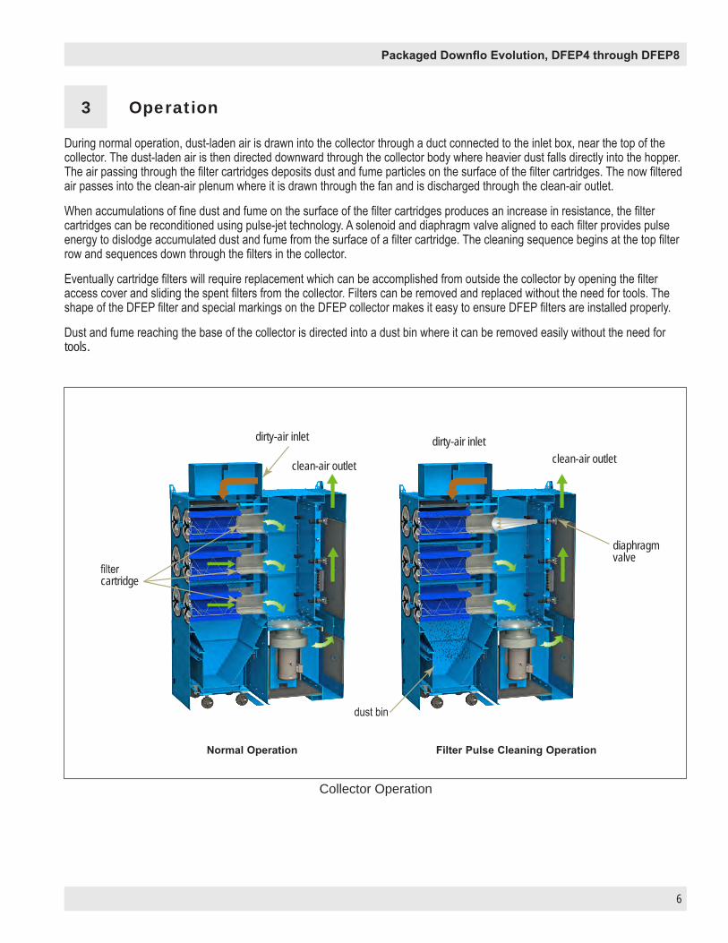
During normal operation, dust-laden air is drawn into the collector through a duct connected to the inlet box, near the top of the collector. The dust-laden air is then directed downward through the collector body where heavier dust falls directly into the hopper. The air passing through the filter cartridges deposits dust and fume particles on the surface of the filter cartridges. The now filtered air passes into the clean-air plenum where it is drawn through the fan and is discharged through the clean-air outlet.
When accumulations of fine dust and fume on the surface of the filter cartridges produces an increase in resistance, the filter cartridges can be reconditioned using pulse-jet technology. A solenoid and diaphragm valve aligned to each filter provides pulse energy to dislodge accumulated dust and fume from the surface of a filter cartridge. The cleaning sequence begins at the top filter row and sequences down through the filters in the collector.
Eventually cartridge filters will require replacement which can be accomplished from outside the collector by opening the filter access cover and sliding the spent filters from the collector. Filters can be removed and replaced without the need for tools. The shape of the DFEP filter and special markings on the DFEP collector makes it easy to ensure DFEP filters are installed properly.
Dust and fume reaching the base of the collector is directed into a dust bin where it can be removed easily without the need for tools.
Collector Operation
3 Operation
dirty-air inlet
filter cartridge
Normal Operation Filter Pulse Cleaning Operation
dust bin
diaphragm valve
dirty-air inlet
clean-air outlet clean-air outlet
7
Donaldson Company, Inc.
Before operating confirm the dust bin is empty, in-place, & properly sealed to the hopper. The dust bin should be emptied daily or more frequently if more than 2/3 full.
• The DFEP collector can be interlocked to start and stop operation with associated fume producing equipment. Observe the DFEP and confirm it starts up when associated equipment is turned on and shuts off when the associated equipment is shut down.
• If the DFEP is operated independently from associated fume producing equipment the DFEP should be turned on before turning on any associated equipment, and shut off after the associated equipment is shut down.
• Observe DFEP filter pressure drop on the Delta P (or Delta P Plus) control. A sudden change in pressure drop may indicate the need for service or maintenance.
• Observe operation and confirm pulse cleaning initiates and is controlled within the operator established High and Low pressure set-points. Excessive differential pressure reduces air volume through the collector. An inability to reduce differential pressure despite pulse cleaning may indicate the need for service in order to restore airflow.
• Observe airflow and adjust the Airflow Control Damper as required to maintain design airflow. Operating the collector above the design airflow may reduce filter life.
DFEP Operation Checklist

8
Packaged Downflo Evolution, DFEP4 through DFEP8
During any service activities there is some potential for exposure to the dust in the collector. Most dusts present safety and health hazards that require precautions. Wear eye, respiratory, head, and other protection equipment suitable for the type of dust when performing any service activities.LOCK-OUT all energy sources prior to performing any service or maintenance on the equipment. The E-Stop feature of the DFEP Control is NOT a Lock-Out device.Electrical service or maintenance must be performed by a qualified electrician.
Dust Bin ServiceThe dust bin should be emptied daily or more frequently as required. Avoid filling more than 2/3 full.
1. Turn off collector.
2. If equippped with a Delta P Plus controller, ensure the downtime cleaning cycle has ended.
3. Open the dust bin access door by rotating the two handles counter clockwise.
4. Reach in and lift the dust bin locking bar up until the bar clears the top of the bin. This should lower the dust bin to the ground.
5. Roll the dust bin from under the collector hopper.
6. Transfer dust from the dust bin to a suitable disposal site. A liner may be used in the dust bin and dust can then be transferred from the dust bin for suitable disposal using the liner. (A vacuum is not required or recommended for servicing the bin.)
a. For the extended capacity dust bin, remove the bag liner retention bar.
b. Close and seal the bag liner.
c. Lift the bag liner from the dust bin and properly dispose of sealed bag liner and dust.
d. Install a fresh bag liner in dust bin.
e. For the extended capacity dust bin, replace bag liner retention bar.
7. Inspect the area around the dust bin and remove any spilled dust.If a vacuum is used to remove dust from below the hopper, make certain it is suitable for the type of dust and the operator is trained in its operation.
8. Inspect and clean the hopper discharge gasket surface. Replace gasket if worn or damaged.
9. With the locking bar up, align and insert the dust bin under the collection hopper until it contacts the mechanical stops on the hopper assembly.
10. Lower dust bin locking bar to its down and locked position.
11. Close and latch dust bin access door by rotating the two handles clockwise.
4 Product Service
9
Donaldson Company, Inc.
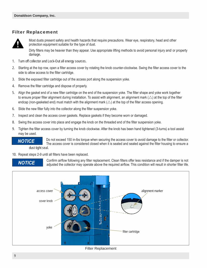
Most dusts present safety and health hazards that require precautions. Wear eye, respiratory, head and other protection equipment suitable for the type of dust.Dirty filters may be heavier than they appear. Use appropriate lifting methods to avoid personal injury and/ or property damage.
1. Turn off collector and Lock-Out all energy sources.
2. Starting at the top row, open a filter access cover by rotating the knob counter-clockwise. Swing the filter access cover to the side to allow access to the filter cartridge.
3. Slide the exposed filter cartridge out of the access port along the suspension yoke.
4. Remove the filter cartridge and dispose of properly.
5. Align the gasket end of a new filter cartridge on the end of the suspension yoke. The filter shape and yoke work together to ensure proper filter alignment during installation. To assist with alignment, an alignment mark (r) at the top of the filter endcap (non-gasketed end) must match with the alignment mark (r) at the top of the filter access opening.
6. Slide the new filter fully into the collector along the filter suspension yoke.
7. Inspect and clean the access cover gaskets. Replace gaskets if they become worn or damaged.
8. Swing the access cover into place and engage the knob on the threaded end of the filter suspension yoke.
9. Tighten the filter access cover by turning the knob clockwise. After the knob has been hand tightened (3-turns) a tool assist may be used.
Do not exceed 150 in-lbs torque when securing the access cover to avoid damage to the filter or collector. The access cover is considered closed when it is seated and sealed against the filter housing to ensure a
dust tight seal.
10. Repeat steps 2-9 until all filters have been replaced.Confirm airflow following any filter replacement. Clean filters offer less resistance and if the damper is not adjusted the collector may operate above the required airflow. This condition will result in shorter filter life.
Filter Replacement
Filter Replacement
access cover
cover knob
yokefilter cartridge
alignment marker

10
Packaged Downflo Evolution, DFEP4 through DFEP8
Afterfilters, commonly HEPA grade, can be employed to monitor primary filter performance. HEPA afterfilters will collect potential emissions from the primary filters. Should such emissions occur, the afterfilters will develop an increased resistance to airflow which can be monitored.
To replace the optional afterfilters on a DFEP:
1. Turn off collector and Lock-Out all energy sources.
2. Remove the rear grated panel guarding the HEPA panel filters from accidental contact.
3. For each afterfilter, loosen the black three-lobe knobs so the hold down tabs can be rotated down and out of contact with the afterfilter frame.
4. Remove the old afterfilter.
5. Install the new afterfilter with the gasket side toward the collector making contact with the metal frame.
6. Rotate the hold down tabs so they make contact with the afterfilter metal frame and hand tighten the black three-lobe knobs.
7. Repeat for each afterfilter.
8. Re-install the protective afterfilter guard.
When requested by the customer, the afterfilter assembly ships loose and installed in the field by a qualified installing contractor.
1. Remove afterfilter guard and HEPA filters.
2. Apply supplied sealant in a figure 8 pattern to exhaust plenum shown in sealant detail.
3. Lift afterfilter housing using supplied eye bolts.
4. Install afterfilter housing, HEPA filters and afterfilter guard using supplied hardware.
Afterfilter Replacement
Afterfilter Field Assembly (when applicable)
afterfilter guard
afterfilter guard
sealant detail
afterfilter
HEPA filter

11
Donaldson Company, Inc.
A damaged diaphragm valve can be serviced, repaired or replaced. To repair or replace a damaged valve:
1. Identify the damaged valve(s) by listening to valve operation during a cleaning cycle or by inspecting the filters (a plugged filter may indicate a damaged cleaning valve).
2. Turn off the collector and Lock-Out all energy sources being certain to close the compressed air shut off valve (owner supplied) and bleed pressure from the DFEP manifold.
3. Remove the rear access panel of the DFEP. For collectors with optional afterfilters, remove the afterfilters.
4. Locate and repair or replace the damaged valve.
5. Re-install the rear access panel (or afterfilters).
6. Open the compressed air shut-off valve and re-pressurize the manifold.
7. Resume DFEP operation.
Solenoid Valve RepairA damaged solenoid valve can be serviced by repairing or replacing the individual solenoids located within the solenoid enclosure.
To repair or replace an individual solenoid:
1. Identify the damaged valve(s) by listening to valve operation during a cleaning cycle or by inspecting the filters (a plugged filter many indicate a damaged cleaning valve).
2. Turn off collector and Lock-Out all energy sources.
3. Close the compressed air shut off valve (owner supplied) and bleed the pressure from the DFEP manifold.
4. Remove the rear access panel of the DFEP. For collectors with optional afterfilters, remove the afterfilters.
5. Locate and mark each tube between the diaphragm valves and the solenoid enclosure to ensure they can be reconnected in their original locations.
6. Disconnect all tubes from the solenoid enclosure.7. Remove the bolts attaching the solenoid enclosure to the manifold.8. On the underside of the solenoid enclosure, unscrew the two screws securing the solenoid cover until the cover
comes loose.9. Remove the solenoid cover.10. Replace or repair the damaged solenoid(s).11. Re-attach the solenoid cover.12. Reconnect the solenoid enclosure to the manifold.13. Reconnect all tubing to original positions on the solenoid enclosure.14. Re-install the rear access panel (or the afterfilters).15. Open the compressed air shut-off valve and re-pressurize the manifold.16. Return power to the collector and resume DFEP operation.
Diaphragm Valve Repair

12
Packaged Downflo Evolution, DFEP4 through DFEP8
Venturi ReplacementTo replace a damaged venturi:
1. Turn off the collector and Lock-Out all energy sources.
2. Open the filter access cover by rotating the knob counter-clockwise.
3. Swing the filter access cover assembly to the open position.
4. Remove the filter (see Filter Replacement section).
5. Open the control panel access door.
6. Access and remove the six thread forming screws securing the damaged venturi to the filter panel, from the control panel access door.
7. Remove the damaged venturi through the filter access door.
8. Remove any residual silicone caulk adhering to the filter panel.
9. Add silicone caulk to the filter panel side (side with holes) of the new venturi.
10. Insert the new venturi through the filter access door and position it against the filter panel by sliding it along the existing yoke.
11. Tighten the six thread forming screws to attach the venturi.
12. Reinstall the filter
13. Close and secure the filter access cover.
14. Close and secure the control panel access door.
15. Return power to the collector and resume DFEP operation.
To replace a damaged filter access cover:
1. Turn off collector and Lock-Out all energy sources.
2. Open the damaged filter access cover assembly by rotating the knob counter-clockwise.
3. Swing the filter access cover assembly to the open position.
4. Remove the Access Cover Pin, Clevis and E-Clip from the collector end of the access cover hinge assembly.
5. Position the new filter access cover assembly and install the Access Cover Pin, Clevis, and E-Clip. Be careful to retain both the upper and lower Hinge Pin Shoulder Spacers.
6. Swing the new filter access cover assembly closed and tighten the knob clockwise. After the knob has been hand tightened (3-turns) a tool assist may be used.
Do not exceed 150 in-lbs torque when securing the access cover to avoid damage to the filter or collector. The access cover is considered closed when it is seated and sealed against the filter housing to
ensure a dust tight seal.
Step 6
Step 9
Filter Access Cover Assembly Replacement

13
Donaldson Company, Inc.
To replace a damaged filter support yoke:
1. Turn off the collector and Lock-Out all energy sources.
2. Open the filter access cover by rotating the knob counter-clockwise.
3. Swing the filter access cover assembly to the open position.
4. Remove the filter (see Filter Replacement).
5. Open the control panel access door.
6. Locate and remove the nuts, fender washers and star washers from the damaged yoke through the control panel access door. Note the sequence of the hardware placement on the yoke threads.
7. Remove the damaged yoke through the filter access door and remove remaining hardware from the damaged yoke.
8. Place hardware (located on the filter side of the filter panel) onto the new yoke (nut, washer, and star washer).
9. Insert the new yoke through the filter access door and insert ends through the corresponding holes in the filter panel.
10. Position the yoke alignment tool (part number AG8265294) over the front threaded end of the yoke and securing the alignment tool to the front face of the collector. This tool ensures optimum positioning for the new yoke.
11. Place remaining hardware (washer and nut on the control panel side of the filter panel) onto the yoke.
12. Hand tighten the hardware on the filter side of the filter panel until it contacts the filter panel and hand tighten hardware on the control panel side of the filter panel. Once all hardware is hand tight, continue to tighten hardware until the yoke is secure.
When properly tightened, the hardware should secure the yoke in the position established by the alignment tool (i.e. when the
alignment tool is removed, the yoke should not spring to a new position).
13. Remove the Yoke Alignment Tool from front of yoke.
14. Reinstall the filter (see Filter Replacement).
15. Close the filter access cover by rotating the knob clockwise.Do not exceed 150 in-lbs torque when securing the access cover to avoid damage to the filter or collector. The access cover is considered closed when it is seated and sealed against the filter housing to
ensure a dust tight seal.
16. Return power to the collector and resume DFEP operation.
Yoke Alignment Tool
Yoke Replacement (Special tool required)
14
Packaged Downflo Evolution, DFEP4 through DFEP8
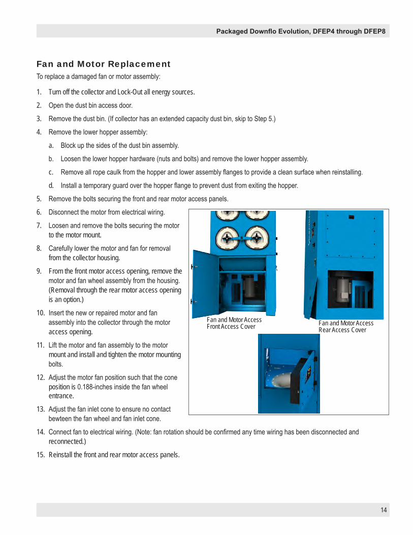
To replace a damaged fan or motor assembly:
1. Turn off the collector and Lock-Out all energy sources.
2. Open the dust bin access door.
3. Remove the dust bin. (If collector has an extended capacity dust bin, skip to Step 5.)
4. Remove the lower hopper assembly:
a. Block up the sides of the dust bin assembly.
b. Loosen the lower hopper hardware (nuts and bolts) and remove the lower hopper assembly.
c. Remove all rope caulk from the hopper and lower assembly flanges to provide a clean surface when reinstalling.
d. Install a temporary guard over the hopper flange to prevent dust from exiting the hopper.
5. Remove the bolts securing the front and rear motor access panels.
6. Disconnect the motor from electrical wiring.
7. Loosen and remove the bolts securing the motor to the motor mount.
8. Carefully lower the motor and fan for removal from the collector housing.
9. From the front motor access opening, remove the motor and fan wheel assembly from the housing. (Removal through the rear motor access opening is an option.)
10. Insert the new or repaired motor and fan assembly into the collector through the motor access opening.
11. Lift the motor and fan assembly to the motor mount and install and tighten the motor mounting bolts.
12. Adjust the motor fan position such that the cone position is 0.188-inches inside the fan wheel entrance.
13. Adjust the fan inlet cone to ensure no contact bewteen the fan wheel and fan inlet cone.
14. Connect fan to electrical wiring. (Note: fan rotation should be confirmed any time wiring has been disconnected and reconnected.)
15. Reinstall the front and rear motor access panels.
Fan and Motor Replacement
Fan and Motor Access Front Access Cover Fan and Motor Access
Rear Access Cover

15
Donaldson Company, Inc.
16. Reinstall the lower hopper assembly for the dust bin. (If you have an extended capacity drum skip to step 17.)
a. Remove the temporary guard from the hopper flange and transport it and any dust to a proper disposal site.
b. Position lower hopper assembly under hopper.
c. Place rope caulk sealant along lower assembly hopper flange.
d. Lift lower hopper assembly into position and tighten hardware.
e. Confirm all rope caulk is in position and tighten all hardware.
17. Position and seal dust bin to hopper.
18. Close the dust bin access door.
19. Return power to the collector and resume DFEP operation.

16
Packaged Downflo Evolution, DFEP4 through DFEP8
Problem Probable Cause RemedyFan/blower does not start
Not wired correctly Check supply voltage and wiring connections. Review motor manufacturer’s wiring diagram, collector wiring schematics, and the National Electric Code and correct any wiring errors.
Electrical circuit down Check power supply and correct any faults to restore power.
Input control circuit down Check wiring to ensure motor starter engages when appropriate.
Damaged motor Replace or repair damaged motor.Fan/blower starts but does not continue to run
Motor operated without sufficient static pressure resistance
Check access covers, dust bin and ducts. All access panels and doors must be secured before operation. Dust bin must be in place and sealed prior to operation. All filters must be installed prior to operation.
Damper control not adjusted properly
Check airflow volume in inlet duct and adjust the damper control until proper airflow is achieved.
Electrical circuit overload protection trips
Confirm the power supply is sufficient to supply all equipment on circuit and matches motor voltage requirements.
Motor starter not properly selected for motor size and voltage
Check starter and replace if necessary for actual motor size and voltage.
Dust emissions at air outlet
Access cover(s) loose Tighten all access covers securely. See Filter Installation.
Filter(s) damaged Inspect gaskets, end caps, liners and media for damage and replace all damaged filters.
Filters not properly installed See Filter Installation.Insufficient air volume Excessive filter restriction Confirm pulse cleaning system is operating correctly.
Correct any faults in the cleaning system (compressed air insufficient or shut off, set point errors, timer control failure, etc.) then check if filter restriction is reduced.
Restriction exists despite pulse cleaning system operation (end of filter life condition)
Remove and replace filters.
Open door, bin connection, or missing duct
Check access covers, dust bin, and ducts. All access panels, and doors must be secured before operation. Dust bin must be in place and sealed prior to operation.
All ducts must be connected to the system prior to operation.
Incorrect collector/fan selection Review published collector/fan performance to confirm required flow can be achieved.
Restriction in hoods, ducts, or other system components.
Inspect system components and remove any restrictions such as material deposits in hoods or ducts.
Troubleshooting
17
Donaldson Company, Inc.
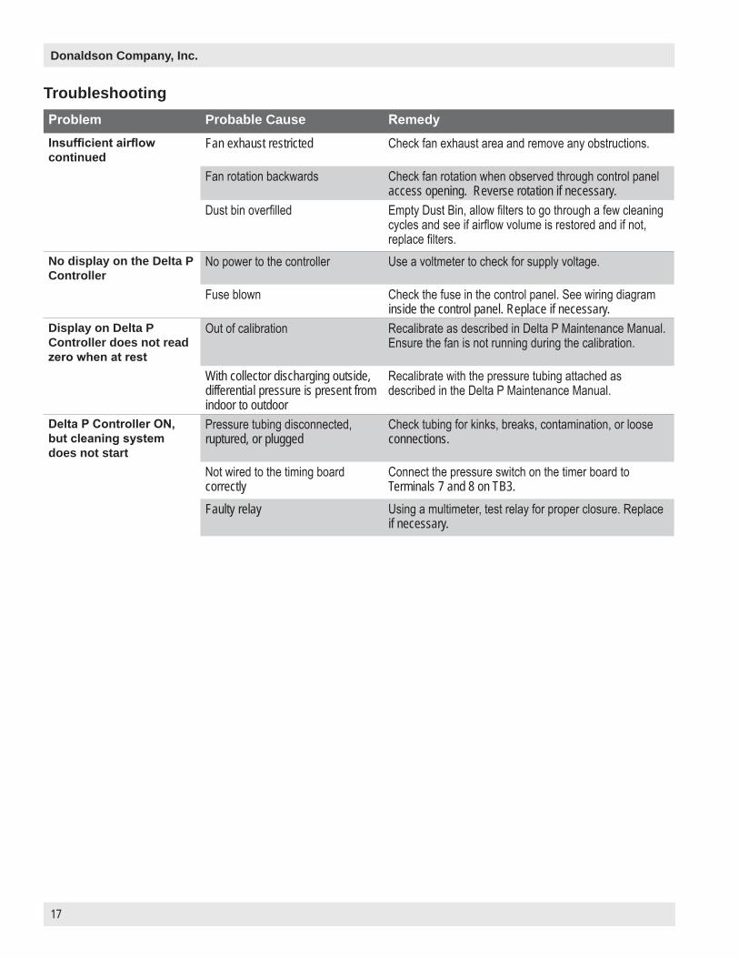
Problem Probable Cause RemedyInsufficient airflow continued
Fan exhaust restricted Check fan exhaust area and remove any obstructions.
Fan rotation backwards Check fan rotation when observed through control panel access opening. Reverse rotation if necessary.
Dust bin overfilled Empty Dust Bin, allow filters to go through a few cleaning cycles and see if airflow volume is restored and if not, replace filters.
No display on the Delta P Controller
No power to the controller Use a voltmeter to check for supply voltage.
Fuse blown Check the fuse in the control panel. See wiring diagram inside the control panel. Replace if necessary.
Display on Delta P Controller does not read zero when at rest
Out of calibration Recalibrate as described in Delta P Maintenance Manual. Ensure the fan is not running during the calibration.
With collector discharging outside, differential pressure is present from indoor to outdoor
Recalibrate with the pressure tubing attached as described in the Delta P Maintenance Manual.
Delta P Controller ON, but cleaning system does not start
Pressure tubing disconnected, ruptured, or plugged
Check tubing for kinks, breaks, contamination, or loose connections.
Not wired to the timing board correctly
Connect the pressure switch on the timer board to Terminals 7 and 8 on TB3.
Faulty relay Using a multimeter, test relay for proper closure. Replace if necessary.
Troubleshooting

18
Packaged Downflo Evolution, DFEP4 through DFEP8
Problem Probable Cause RemedyPulse cleaning never stops
Pressure switch not wired to the timer board correctly
Connect the pressure switch on the timer board to Terminals 7 and 8 on TB3.
Pressure switch terminals on the timer board jumpered
Remove jumper wire on Solid-State Timer board before wiring to the Delta P Control.
High Pressure On or Low Pressure Off setpoint not adjusted for system conditions
Adjust setpoints to current conditions.
Pressure tubing disconnected, ruptured, plugged, or kinked
Check tubing for kinks, breaks, contamination, or loose connections.
Alarm light is ON Alarm setpoint too low Adjust to a higher value.Excess pressure drop Check cleaning system and compressed air supply.
Replace filters if filters do not clean down.Pressure tubing disconnected, ruptured, plugged, or kinked
Check tubing for kinks, breaks, contamination, or loose connections.
Delta P arrow keys do not work
Improper operation Press and hold one of the three setpoint keys to use arrow keys.
Programming keys disabled Remove the Program Disable jumper from Terminals 3 and 4 on TB2.
Cleaning light is ON, but cleaning system not functioning
Improper wiring Check wiring between the Delta P Control and the timer board, and between the timer board and solenoid valve coils.
Defective solenoids Check all solenoid coils for proper operation.Timer board not powered Check power ON light on timer board's LED display. If not
illuminated, check the supply voltage to the timer board. Check the fuse on the timer board. Replace if necessary.
Timer board defective If LED is illuminated, observe the output display. Install a temporary jumper across the pressure switch terminals. Output levels should flash in sequence. Check output using a multimeter set to 150-Volt AC range. Measure from SOL COM to a solenoid output. The needle will deflect when LED flashes for that output if voltage is present. If LED's do not flash, or if no voltage is present at output terminals during flash, replace the board.

A1
Donaldson Company, Inc.
Appendix A - Collector Installation
A2
Packaged Downflo Evolution, DFEP4 through DFEP8
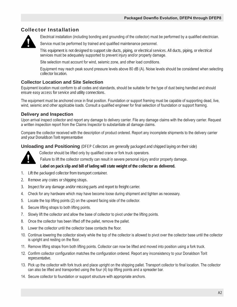
Collector InstallationElectrical installation (including bonding and grounding of the collector) must be performed by a qualified electrician.Service must be performed by trained and qualified maintenance personnel.This equipment is not designed to support site ducts, piping, or electrical services. All ducts, piping, or electrical services must be adequately supported to prevent injury and/or property damage.Site selection must account for wind, seismic zone, and other load conditions.Equipment may reach peak sound pressure levels above 80 dB (A). Noise levels should be considered when selecting collector location.
Collector Location and Site SelectionEquipment location must conform to all codes and standards, should be suitable for the type of dust being handled and should ensure easy access for service and utility connections.
The equipment must be anchored once in final position. Foundation or support framing must be capable of supporting dead, live, wind, seismic and other applicable loads. Consult a qualified engineer for final selection of foundation or support framing.
Delivery and InspectionUpon arrival inspect collector and report any damage to delivery carrier. File any damage claims with the delivery carrier. Request a written inspection report from the Claims Inspector to substantiate all damage claims.
Compare the collector received with the description of product ordered. Report any incomplete shipments to the delivery carrier and your Donaldson Torit representative
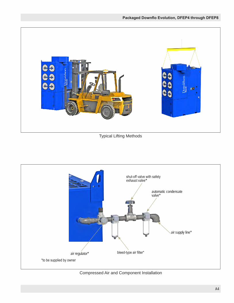
Unloading and Positioning (DFEP Collectors are generally packaged and shipped laying on their side)Collector should be lifted only by qualified crane or fork truck operators.Failure to lift the collector correctly can result in severe personal injury and/or property damage.Label on pack slip and bill of lading will state weight of the collector as delivered.
1. Lift the packaged collector from transport container.2. Remove any crates or shipping straps.3. Inspect for any damage and/or missing parts and report to freight carrier.4. Check for any hardware which may have become loose during shipment and tighten as necessary.5. Locate the top lifting points (2) on the upward facing side of the collector.6. Secure lifting straps to both lifting points.7. Slowly lift the collector and allow the base of collector to pivot under the lifting points.8. Once the collector has been lifted off the pallet, remove the pallet.9. Lower the collector until the collector base contacts the floor.10. Continue lowering the collector slowly while the top of the collector is allowed to pivot over the collector base until the collector
is upright and resting on the floor.11. Remove lifting straps from both lifting points. Collector can now be lifted and moved into position using a fork truck.12. Confirm collector configuration matches the configuration ordered. Report any inconsistency to your Donaldson Torit
representative.13. Pick up the collector with fork truck and place upright on the shipping pallet. Transport collector to final location. The collector
can also be lifted and transported using the four (4) top lifting points and a spreader bar.14. Secure collector to foundation or support structure with appropriate anchors.

A3
Donaldson Company, Inc.
Provisional Anchor Bolt RecommendationsThe quantity of anchor bolts should match the number of holes provided in the base plates of the collector. Anchor diameter is typically 1/8-inch less than the baseplate hole diameter. Anchors should project a minimum of 1 ¾ -inch and account for nut, washer, baseplate, and shims/grout.
Consider Hilti HIT-HY 200 Anchor Systems or equivalent.
Typical Foundation Anchor
InstallationElectrical installation must be performed by a qualified electrician.Compressed air installation must be performed by a qualified pipe fitter.Duct fabrication and installation must be performed by a qualified tinsmith or contractor.This equipment is not designed to support site ducts, piping, or electrical services. All ducts, piping, or electrical services must be adequately supported to prevent injury and/or property damage.
Collector ConnectionsAfter the collector has been positioned and secured in the final location continue with installation.
1. Complete electrical connections to the collector electrical junction box. The DFEP ships from the factory with the internal electrical wiring completed for the fan and cleaning controls.
2. Complete connection to a compressed air supply. Installation should include a shut-off valve, and bleed type regulator with gauge, filter, and automatic condensate valve (supplied by owner).
Purge compressed-air lines to remove debris before connecting to the collector.
3. Connect duct and fittings.
4. Install any ancillary equipment such as fire and/or explosion mitigation devices.
Anchor should project a minimum of 1 3/4-in and account for nut, washer, base plate and shims/grout.
Embedment depth (suitable for the physical properties of the foundation).
A4
Packaged Downflo Evolution, DFEP4 through DFEP8
Typical Lifting Methods
Compressed Air and Component Installation
shut-off valve with safety exhaust valve*
automatic condensate valve*
air supply line*
bleed-type air filter*air regulator**to be supplied by owner

A5
Donaldson Company, Inc.
DFEP8 Front High Inlet InstallationOn a DFEP8 equipped with a Front High Inlet only, the inlet transition ships loose.1. Install transition while collector is still flat on the pallet.2. Apply supplied sealant to top plenum in a figure 8 pattern shown in sealant detail.3. Install transition on top plenum using supplied hardware.
top inlet module
sealant detail
front inlet
hex boltflat washer see sealant
detail
A6
Packaged Downflo Evolution, DFEP4 through DFEP8
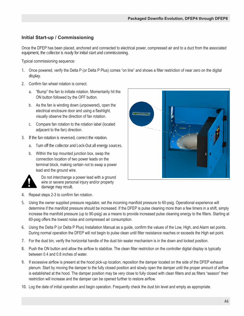
Once the DFEP has been placed, anchored and connected to electrical power, compressed air and to a duct from the associated equipment, the collector is ready for initial start and commissioning.
Typical commissioning sequence:
1. Once powered, verify the Delta P (or Delta P Plus) comes “on line” and shows a filter restriction of near zero on the digital display.
2. Confirm fan wheel rotation is correct.
a. “Bump” the fan to initiate rotation. Momentarily hit the ON button followed by the OFF button.
b. As the fan is winding down (unpowered), open the electrical enclosure door and using a flashlight, visually observe the direction of fan rotation.
c. Compare fan rotation to the rotation label (located adjacent to the fan) direction.
3. If the fan rotation is reversed, correct the rotation.
a. Turn off the collector and Lock-Out all energy sources.
b. Within the top mounted junction box, swap the connection location of two power leads on the terminal block, making certain not to swap a power lead and the ground wire.
Do not interchange a power lead with a ground wire or severe personal injury and/or property damage may result.
4. Repeat steps 2-3 to confirm fan rotation.
5. Using the owner supplied pressure regulator, set the incoming manifold pressure to 60-psig. Operational experience will determine if the manifold pressure should be increased. If the DFEP is pulse cleaning more than a few timers in a shift, simply increase the manifold pressure (up to 90-psig) as a means to provide increased pulse cleaning energy to the filters. Starting at 60-psig offers the lowest noise and compressed air consumption.
6. Using the Delta P (or Delta P Plus) Installation Manual as a guide, confirm the values of the Low, High, and Alarm set points. During normal operation the DFEP will not begin to pulse clean until filter resistance reaches or exceeds the High set point.
7. For the dust bin, verify the horizontal handle of the dust bin sealer mechanism is in the down and locked position.
8. Push the ON button and allow the airflow to stabilize. The clean filter restriction on the controller digital display is typically between 0.4 and 0.8 inches of water.
9. If excessive airflow is present at the hood pick-up location, reposition the damper located on the side of the DFEP exhaust plenum. Start by moving the damper to the fully closed position and slowly open the damper until the proper amount of airflow is established at the hood. The damper position may be very close to fully closed with clean filters and as filters “season” their restriction will increase and the damper can be opened further to restore airflow.
10. Log the date of initial operation and begin operation. Frequently check the dust bin level and empty as appropriate.
Initial Start-up / Commissioning

A7
Donaldson Company, Inc.
Once the collector has reached the end of operational life it will need to be decommissioned.
During decommissioning, there is potential for exposure to the dust in the collector. Most dusts present safety and health hazards that require precautions\. Wear eye, respiratory, head, and other protection equipment suitable for the type of dust when performing any decommissioning activities.LOCK-OUT all energy sources prior to performing any decommissioning activities on the equipment. The E-Stop feature of the DFEP Control is NOT a Lock-Out Device.Electrical service must be performed by a qualified electrician.Disconnection of compressed air must be performed by a qualified pipe fitter.Disconnection of ducts must be performed by a qualified tinsmith or contractor.
1. Turn off the collector and Lock-Out all energy sources.
2. Remove all filters from the collector and dispose of in a suitable fashion for the dust in the collector. (See Filter Replacement for removal instructions). Close and seal filter access covers after filters are removed.
3. Empty the dust bin of any residual dust and reseal to hopper. (See Dust Bin Service instructions)
4. Disconnect compressed air supply from the collector and remove any associated pipe or fittings from the exterior of the collector.
5. Disconnect electrical power from the collector and remove any associated conduit or hardware from the exterior of the collector.
6. Disconnect all ducts from the collector. Seal the inlet and discharge openings of the collector with shipping covers to prevent residual dust from migrating from the collector during transport for disposal.
7. Remove anchor bolts and hardware from the collector.
8. Pick up the collector with a fork truck and place it upright in a location suitable to prepare it for transportation. (See Installation instructions for lifting guidance.)
9. Using lifting points on top of the collector, carefully tip the collector onto its side and lower it onto a suitable transport base/pallet.
10. Secure the collector to a suitable transport carrier and transport to a disposal site suitable for the dust in the collector.
Decommissioning Collector

A8
Packaged Downflo Evolution, DFEP4 through DFEP8
Model Number _________________________________ Serial Number ___________________________________
Ship Date _____________________________________ Installation Date __________________________________
Filter Type_____________________________________________________________________________________
Dust Being Collected ____________________________________________________________________________
Dust Properties: Kst _______________Pmax ______________ MIE ____________ MEC __________________
Accessories ___________________________________________________________________________________
Other ________________________________________________________________________________________
_____________________________________________________________________________________________
Collector Information (Process Owner to complete and retain for your records)
Service NotesDate Service Performed Notes
A9
Donaldson Company, Inc.
Service NotesDate Service Performed Notes

Packaged Downflo Evolution, DFEP4 through DFEP8
A10
Donaldson warrants to the original purchaser only that the Goods will be free from defects in material and manufacture for the applicable time periods stated below: (1) Major structural components for a period of ten (10) years from the date of shipment; (2) Non-Structural, Donaldson-built components and accessories including Donaldson Airlocks, TBI Fans, TRB Fans, Fume Collector products, Donaldson built electrical control components, and Donaldson-built Afterfilter housings for a period of twelve (12) months from date of shipment; and (3) Donaldson-built filter elements for a period of eighteen (18) months from date of shipment. Buyer is solely responsible for determining if goods fit Buyer’s particular purpose and are suitable for Buyer’s process and application. Seller’s statements, engineering and technical information, and recommendations are provided for the Buyer’s convenience and the accuracy or completeness thereof is not warranted. If, after Seller receives written notice, within the warranty period, that any goods allegedly do not meet Seller’s warranty, and Seller, in its sole discretion, determines that such claim is valid, Seller’s sole obligation and Buyer’s exclusive remedy for breach of the foregoing warranty or any Seller published warranty, will be, at Seller’s option, either: (i) repair or replacement of such goods or (ii) credit or refund to Buyer for the purchase price from Seller. In the case of repair or replacement, Seller will be responsible for the cost of shipping the parts but not for labor to remove, repair, replace or reinstall the allegedly defective goods. Refurbished goods may be used to repair or replace the goods and the warranty on such repaired or replaced goods shall be the balance of the warranty remaining on the goods which were repaired or replaced. Any repair or rework made by anyone other than Seller is not permitted without prior written authorization by Seller, and voids the warranty set forth herein. Seller warrants to Buyer that it will perform services in accordance with the Sales Documents using personnel of required skill, experience and qualifications and in a professional and workmanlike manner in accordance with generally recognized industry standards for similar services. With respect to any services subject to a claim under the warranty set forth above, Seller shall, in its sole discretion, (i) repair or re-perform the applicable services or (ii) credit or refund the price of such services at the pro rata contract rate and such shall be Seller’s sole obligation and the exclusive remedy for breach of the foregoing warranty on services. Products manufactured by a third party (“Third Party Product”) may constitute, contain, be contained in, incorporated into, attached to or packaged together with, the goods. Buyer agrees that: (a) Third Party Products are excluded from Seller’s warranty in this Section 7 and carry only the warranty extended by the original manufacturer, and (b) Seller’s liability in all cases is limited to goods of Seller’s design and manufacture only. EXCEPT FOR SELLER’S WARRANTY OF TITLE TO THE GOODS, SELLER EXPRESSLY DISCLAIMS AND EXCLUDES ALL OTHER WARRANTIES WHATSOEVER, WHETHER, EXPRESSED OR IMPLIED, ORAL, STATUTORY, OR OTHERWISE, INCLUDING BUT NOT LIMITED TO MERCHANTABILITY, FITNESS FOR A PARTICULAR PURPOSE, NON-INFRINGEMENT OF THIRD PARTY INTELLECTUAL PROPERTY AND ANY WARRANTIES ARISING FROM TECHNICAL ADVICE OR RECOMMENDATIONS, COURSE OF DEALING OR OF PERFORMANCE, CUSTOM OR USAGE OF TRADE. Seller’s obligations do not cover normal wear and tear or deterioration, defects in or damage to any goods resulting from improper installation, accident or any utilization, maintenance, repair or modification of the goods, or any use that is inconsistent with Seller’s instructions as to the storage, installation, commissioning or use of the goods or the designed capabilities of the goods or that, in its sole judgment, the performance or reliability thereof is adversely affected thereby, or which is subjected to abuse, mishandling, misuse or neglect or any damage caused by connections, interfacing or use in unforeseen or unintended environments or any other cause not the sole fault of Seller, and shall be at Buyer’s expense. Seller’s warranty is contingent upon the accuracy of all information provided by Buyer. Any changes to or inaccuracies in any information or data provided by Buyer voids this warranty. Seller does not warrant that the operation of the goods will be uninterrupted or error-free, that the functions of the goods will meet Buyer’s or its customer’s requirements unless specifically agreed to, or that the goods will operate in combination with other products selected by Buyer or Buyer’s customer for its use.The terms of this warranty may only be modified by a special warranty document signed by a Director, General Manager or Vice President of Donaldson. To ensure proper operational performance of your equipment, use only genuine Donaldson replacement parts.
This Product is provided subject to and conditioned upon Donaldson’s Terms of Sale (“Terms”), a current copy of which is located at termsofsale.donaldson.com. These Terms are incorporated herein by reference. By purchasing or using this Product, the user accepts these Terms. The Terms are available on our website or by calling our customer service line at 1-800-365-1331.
Donaldson Industrial Air Filtration Warranty

Donaldson Company, Inc. is the leading designer and manufacturer of dust, mist, and fume collection equipment used to control industrial-air pollutants. Our equipment is designed to help reduce occupational hazards, lengthen machine life, reduce in-plant maintenance requirements, and improve product quality.
Parts and ServiceFor genuine Donaldson replacement filters and parts, call the Parts Express Line. For faster service, have collector’s model and serial number, quantity, part number, and description available.
Donaldson Company, Inc. Torit PO Box 1299 Minneapolis, MN 55440-1299 U.S.A.
800-365-1331 USA 800-343-3639 within Mexico +52 (449) 300 24 42 Latin America
[email protected] donaldsontorit.com
© 2017 Donaldson Company, Inc. IOM AG8354401 (ENG), Revision 1Printed in USA August 2018