Embed Size (px)
Citation preview
This is the safety alert symbol. It is used to alert you to potential personal injury hazards. Obey all safety messages that follow this symbol to avoid possible injury or death.
This manual is property of the owner. Leave with the collector when set-up and start-up are complete. Donaldson Company reserves the right to change design and specifications without prior notice.
Illustrations are for reference only as actual product may vary.
Downflo® Oval DFO 1-1, 2-2 and 3-3
Installation and Operation ManualInstallation, Operation, and Service Information
IOM AD3092901 (ENG)Revision 10
EnglishMaster Language

Donaldson Company, Inc.
Process owners/operators have important responsibilities relating to combustible hazards. Process owners/operators must determine whether their process creates combustible dust,
fume, or mist. If combustible dust, fume, or mist is generated, process owners/operators should at a minimum:
• Comply with all applicable codes and standards. Among other considerations, current NFPA standards require owners/operators whose processes involve potentially combustible materials to have a current Hazard Analysis, which can serve as the foundation for their process hazard mitigation strategies.
• Prevent all ignition sources from entering any dust collection equipment.
• Design, select, and implement fire and explosion mitigation, suppression, and isolation strategies that are appropriate for the risks associated with their application.
• Develop and implement maintenance work practices to maintain a safe operating environment, ensuring that combustible dust, fume, or mist does not accumulate within the plant.
Donaldson recommends process owners/operators consult with experts to insure each of these responsibilities are met.
As a manufacturer and supplier of Industrial Filtration Products, Donaldson can assist process owners/operators in the selection of filtration technologies. However, process owners/operators retain all responsibility for the suitability of fire and explosion hazard mitigation, suppression, and isolation strategies. Donaldson assumes no responsibility or liability for the suitability of any fire and/or explosion mitigation strategy, or any items incorporated into a collector as part of an owner/operators hazard mitigation strategy.
Improper operation of a dust control system may contribute to conditions in the work area or facility that could result in severe personal injury and product or property damage. Check that all collection equipment is properly selected and sized for the intended use.
DO NOT operate this equipment until you have read and understand the instruction warnings in the Installation and Operations Manual. For a replacement manual, contact Donaldson Torit.
This manual contains specific precautionary statements relative to worker safety. Read thoroughly and comply as directed. Discuss the use and application of this equipment with a Donaldson Torit representative. Instruct all personnel on safe use and maintenance procedures.
Model Number _____________________________ Serial Number ______________________________
Ship Date _________________________________ Installation Date _____________________________
Customer Name _______________________________________________________________________
Address _____________________________________________________________________________
____________________________________________________________________________________
Filter Type ____________________________________________________________________________
Accessories __________________________________________________________________________
Other ________________________________________________________________________________
Data Sheet

Downflo Oval, DFO 1-1 to 3-3
i
DANGER indicates a hazardous situation which, if not avoided, will result in death or serious injury.
WARNING indicates a hazardous situation which, if not avoided, could result in death or serious injury.
CAUTION, used with the safety alert symbol, indicates a hazardous situation which, if not avoided, could result in minor or moderate injury.
NOTICE is used to address practices not related to personal injury that may result in damage to equipment.
Contents
Description ................................................................................1Purpose and Intended Use ....................................................1Rating and Specification Information ...................................2Operation ...................................................................................3Inspection on Arrival ...............................................................4Installation Codes and Procedures ......................................4Installation.................................................................................4
Foundations or Support Framing .......................................5Collector Location ................................................................5Site Selection .......................................................................5
Rigging Instructions.................................................................5Hoisting Information ............................................................5
Typical Installation ...................................................................6Standard Equipment ................................................................7
Collector Anchoring .............................................................8Compressed Air Installation ...............................................9Electrical Wiring ...................................................................9
Control Panel and Motor Wiring .........................................10Control Panels and Solenoid Specifications .................1310-Gallon Pail Pack ............................................................1425-Gallon Dust Bin ..............................................................14Exhaust Damper ................................................................14
Preliminary Start-Up Check .................................................15
Maintenance Information ....................................................16Operational Checklist ........................................................16Filter Removal and Installation .........................................16Dust Disposal ......................................................................17Compressed Air Components ...........................................17Split Taper™ Bushing Mounting Instructions ...............19
Optional Equipment................................................................2025-Gallon Dust Container ..................................................20Sealer Gear Installation ....................................................21Delta P Control ....................................................................22Caster Assembly .................................................................23HEPA Afterfilter Installation..............................................24Extraction Arm and Adapter Installation ........................25Explosion Vent ....................................................................27Sprinkler ...............................................................................27
Troubleshooting ......................................................................28Service Notes .........................................................................31

1
Donaldson Company, Inc.
Combustible materials such as buffing lint, paper, wood, metal dusts, weld fume, or flammable coolants or solvents represent potential fire and/or explosion hazards. Use special care when
selecting, installing, and operating all dust, fume, or mist collection equipment when such combustible materials may be present in order to protect workers and property from serious injury or damage due to a fire and/or explosion.
Consult and comply with all National and Local Codes related to fire and/or explosion properties of combustible materials when determining the location and operation of all dust, fume, or mist collection equipment.
Standard Donaldson Torit equipment is not equipped with fire extinguishing or explosion protection systems.
Downflo Oval collectors are widely used on nuisance dust where the load to the collector is less than two grains per cubic foot. Some typical point-of-use applications include abrasive blasting, thermal cutting, grinding, pharmaceutical blending and packaging, powder paint applications, sand handling, and welding. Each application is different and selecting the correct filter for the application and type of dust collected is important. Contact Donaldson Torit for selection assistance.
• Ambient, extremely fine, and non-fibrous dust, typically use Ultra Web® filter cartridges which offer high efficiency and performance on fine particulate.
• Fibrous dusts often benefit from a cartridge with an open-pleat design, such as Fibra-Web®.
• Operations involving high temperature and high humidity may require special attention. Temperature, moisture content, and chemistry issues may require custom collector modifications.
• Hygroscopic dust such as fertilizer, salt, and sugar should be handled under a controlled, low-humidity environment.
• Flammable or explosive dust may require customized collector design options.
• Applications with high hydrocarbon or high oil content may require special treatment or filter media.
Description
The Downflo Oval is a dust collector with oval, cartridge-style filters. The downward airflow design delivers high filtration efficiency while using less energy. The filters for DFO 1-1 are pulse-cleaned off-line while filters for DFO 2-2 and DFO 3-3 can be pulse-cleaned on- or off-line, depending on the type of cleaning control options selected. All models are one-filter deep collectors; model DFO 1-1 is a single filter collector, model DFO 2-2 is a two filter high collector, and model DFO 3-3 is a three filter high collector.
Options include various cleaning controls with and without motor starter controls, HEPA afterfilter packs, Bag-Out, and various dust container options.
Purpose and Intended Use
Misuse or modification may result in severe personal injury and/or
property damage.
Do not misuse or modify.

Downflo Oval, DFO 1-1 to 3-3
2
Collectors are rated for the following loads as calculated per relevant sections of the IBC 2012 code*:
Basic Wind Speed & Exposure ............90 mph, Exposure CSeismic Spectral Acceleration, S
s ................................. 1.5 g
Seismic Spectral Acceleration, S1 ................................. 0.6 g
Installed Collector Base Elevation ...............................GradeRisk Category .......................................................................... IICompressed air, psig .............................................................60Housing rating, inches water gauge ............................... - 20Control power ...............................................120-Volt 50/60 Hz
*If collector was supplied with a Record Drawing, the specifications on the drawing will supersede the standard specifications above.
Front View 1-1 Front view 2-2
Front View 3-3 Typical Side View
Rating and Specification Information
3
Donaldson Company, Inc.
Operation
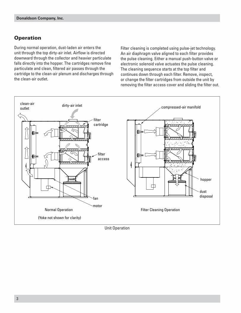
During normal operation, dust-laden air enters the unit through the top dirty-air inlet. Airflow is directed downward through the collector and heavier particulate falls directly into the hopper. The cartridges remove fine particulate and clean, filtered air passes through the cartridge to the clean-air plenum and discharges through the clean-air outlet.
dirty-air inletclean-airoutlet
motor
fan
filtercartridge
hopper
compressed-air manifold
filteraccess
dustdisposal
Normal Operation Filter Cleaning Operation
(Yoke not shown for clarity)
Unit Operation
Filter cleaning is completed using pulse-jet technology. An air diaphragm valve aligned to each filter provides the pulse cleaning. Either a manual push-button valve or electronic solenoid valve actuates the pulse cleaning. The cleaning sequence starts at the top filter and continues down through each filter. Remove, inspect, or change the filter cartridges from outside the unit by removing the filter access cover and sliding the filter out.
Downflo Oval, DFO 1-1 to 3-3
4
Inspection on Arrival
1. Inspect collector upon delivery.
2. Report any damage to the delivery carrier.
3. Request a written inspection report from the Claims Inspector to substantiate any damage claim.
4. File claims with the delivery carrier.
5. Compare collector received with description of product ordered.
6. Report incomplete shipments to the delivery carrier and your Donaldson Torit representative.
7. Remove crates and shipping straps. Remove loose components and accessory packages before lifting collector from truck.
8. Check for hardware that may have loosened during shipping.
9. Use caution removing temporary covers.
Installation Codes and Procedures
Codes may regulate recirculating filtered air in your facility.
Consult with the appropriate authorities having jurisdiction to ensure compliance with all national and local codes regarding recirculating filtered air.
Safe and efficient operation of the collector depends on proper installation.
Authorities with jurisdiction should be consulted before installing to verify local codes and installation procedures. In the absence of such codes, install collector according to the National Electric Code, NFPA No. 70-latest edition and NFPA 91 (NFPA 654 if combustible dust is present).
A qualified installation and service agent must complete installation and service of this equipment.
All shipping materials, including shipping covers, must be removed from the collector prior to or during collector installation.
Failure to remove shipping materials from the collector will
compromise collector performance.
Inspect collector to ensure all hardware is properly installed and tight prior to operating collector.
Installation
Use proper equipment and adopt all safety precautions needed for
servicing equipment.
Electrical service or maintenance work must be performed by a qualified electrician and comply with all applicable national and local codes.
Turn power off and lock out electrical power sources before performing service or maintenance work.
Do not install in classified hazardous atmospheres without an enclosure rated for the application.
Turn compressed air supply OFF, bleed and lock out lines before performing service or maintenance work.
Site selection must account for wind, seismic zone, and other
load conditions when selecting the location for collectors.
Codes may regulate acceptable locations for installing dust collectors. Consult with the appropriate authorities having jurisdiction to ensure compliance with all national and local codes regarding dust collector installation.
Collectors must be anchored in a manner consistent with local code requirements. Anchors must be sufficient to support dead, live, seismic, and other anticipated loads.
Consult a qualified engineer for final selection of anchorage.
Do not set compressed-air pressure above 60-psig as
component damage can occur.
All compressed air components must be sized to meet the system requirements of 60-psig supply pressure.
The compressed-air supply must be oil and moisture free. Contamination in the compressed air used to clean filters will result in poor cleaning, cleaning valve failure, or poor collector performance.
Purge compressed air lines to remove debris before connecting to the collector’s compressed air manifold.

5
Donaldson Company, Inc.
Collector Location
Donaldson Torit equipment is not designed to support site installed
ducts, interconnecting piping, or electrical services. All ducts, piping, or electrical services must be adequately supported to prevent severe personal injury and/or property damage.
When hazardous conditions or materials are present, consult with local authorities for the proper location of the collector.
Dust collection equipment may reach peak sound pressure
levels above 80 dB (A). Noise levels should be considered when selecting collector location.
Locate the collector to ensure easy access to electrical and compressed air connections, to simplify solids collection container handling and routine maintenance, and to ensure the straightest inlet and outlet ducts.
Foundations or Support Framing
Prepare the foundation or support framing in the selected location. Foundation or support framing must comply with local code requirements and may require engineering.
Foundation and support framing must be capable of supporting dead, live, wind, seismic and other applicable loads. Consult a qualified engineer for final selection of foundation or support framing.
Site Selection
This collector can be located on a foundation or structural framing.
Provide clearance from heat sources and avoid any interference with utilities when selecting the location.
The collector is suitable for indoor installation. Reference the Rating and Specification Information.
Rigging Instructions
Suggested Tools & EquipmentClevis Pins and Clamps Lifting SlingsCrane or Forklift Pipe SealantDrift Pins Pipe WrenchesDrill and Drill Bits ScrewdriversEnd Wrenches Socket WrenchesAdjustable Wrench Spreader BarsTorque Wrench (inch/lbs, 9/16-in Socket)
Hoisting Information
Failure to lift the collector correctly can result in severe
personal injury and/or property damage.
Use appropriate lifting equipment and adopt all safety precautions needed for moving and handling the equipment.
A crane or forklift is recommended for unloading, assembly, and installation of the collector.
Location must be clear of all obstructions, such as utility lines or roof overhang.
Use all lifting points provided.
Use clevis connectors, not hooks, on lifting slings.
Check the Specification Control drawing for weight and dimensions of the collector and components to ensure adequate crane capacity.
Allow only qualified crane or forklift operators to lift the equipment.
Refer to applicable OSHA regulations and local codes when using cranes, forklifts, and other lifting equipment.
Lift collector and accessories separately and assemble after collector is in place.
Note: Collectors with explosion vents are not available in portable configurations.
Portable collectors require special installation accommodations.

Downflo Oval, DFO 1-1 to 3-3
6
Typical Installation
Typical Installation

7
Donaldson Company, Inc.
Standard Equipment
Standard collectors include a fan, motor, control panel, 10-gallon dust container, and an exhaust silencer and damper. Depending on the type of control selected, the motor may or may not be pre-wired. Otherwise, the unit is fully assembled and ready to connect to electrical supply, compressed air, and ductwork. A detailed drawing, shipped with each collector, provides weight, specifications, and unit dimensions including anchor bolt locations for the collector’s base plate.
Cleaning Controls
All units include standard cleaning controls that are manually- or timer-controlled depending on the model and options selected. Controls are available in a variety of voltages and are available in one of four basic types:
1. Manual push-button with or without motor starter.
2. Downtime cleaning with or without motor starter.
3. Delta P cleaning with or without motor starter.
4. Manual push-button, Delta P, or downtime cleaning without motor starter in a remote-mount option.
Model DFO 1-1 standard controls include a manual motor starter that is prewired to the motor and a push-button valve for pulse cleaning control. Options include downtime cleaning with or without motor starter and remote-mount, downtime cleaning without motor starter.
Models DFO 2-2 and DFO 3-3 standard controls include downtime cleaning without a motor starter. Available options include downtime cleaning with a motor starter, remote-mount downtime cleaning without motor starter, Delta P cleaning with or without motor starter, and remote-mount Delta P cleaning without motor starter.
All control panels, except remote-mount, are located inside the unit.
Manual Motor Starter Option
The manual motor starter is the standard option for Model DFO 1-1 and is not available for other models. It is prewired to the motor and filter cleaning is completed using a separate, manual push-button valve located next to the motor starter.
Downtime Cleaning Option
Primarily used for intermittent duty, light dust-load applications, the downtime cleaning option provides automatic, downtime filter cleaning when the collector is turned OFF. Downtime cleaning WILL occur every time the unit is shut down. The valves start to pulse one minute after the unit is shut down and continue pulsing every 10-seconds for 3 minutes to reduce the differential pressure.
Downtime cleaning without motor starter is standard for Models DFO 2-2 and DFO 3-3. The option is specified at the time of order and available with and without a motor starter.
Delta P Cleaning Option
Primarily used for continuous duty or heavy dust-load applications, the Delta P option provides automatic, on-line filter cleaning. The high- and low-pressure setpoints initiate the pulse cleaning cycle. The pulse-cleaning cycle begins when the filter pressure reaches the high-pressure setpoint. The valves continue to pulse every 10 seconds until the low-pressure setpoint is reached.
The Delta P option is available for models DFO 2-2 and DFO 3-3 only, with or without a motor starter.
Remote-Mount Cleaning Option
Primarily used in applications that require the cleaning controls to be located away from a hazardous environment, remote-mount controls are available with downtime cleaning and Delta P cleaning options. Remote downtime cleaning is available for all three models while the remote Delta P is available for models DFO 2-2 and DFO 3-3 only. This option is specified at the time of order and the collector is equipped with a 115-Volt AC NEMA 12 solenoid valve enclosure. Explosion-protected units include a NEMA 9 dust explosion-proof solenoid enclosure. Contact Donaldson for information about a NEMA 7 gas explosion-proof solenoid enclosure.
Motor starters for remote-mount cleaning options are customer-supplied.

Downflo Oval, DFO 1-1 to 3-3
8
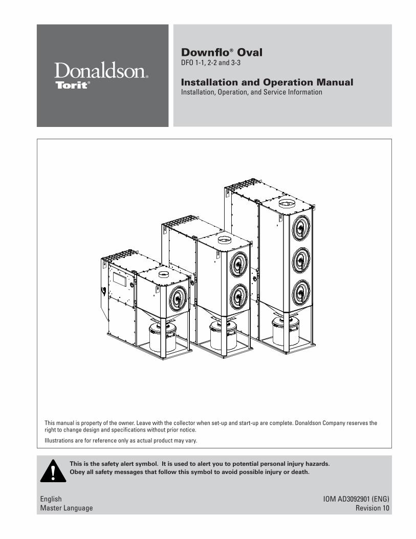
Anchor should projecta minimum of 1 3/4-inand account for nut, washer, base plate and shims/grout.
Embedment depth
Typical Foundation Anchor
Provisional Anchor Bolt Recommendations
1. Consider Hilti HIT-HY 200 Anchor System or equivalent. Quantity of anchor bolts should match the number of holes provided in the base plates.
2. Anchor diameter is typically 1/8-in less than baseplate hole diameter.
3. Corrosive environment or outdoor installation may require stainless steel anchors.
Collector Anchoring
Anchors must comply with local code requirements and must be
capable of supporting dead, live, wind, seismic, and other applicable loads.
Anchor sizes shown are provisional, as final anchor sizing will depend on jobsite load conditions, collector location, foundation/framing design variables and local codes.
Consult a qualified engineer for final selection of suitable anchors.
Tighten all hardware before removing crane to prevent
personal injury and/or property damage.
Prepare the foundation or support framing in the selected location. Locate and install anchors.

9
Donaldson Company, Inc.
Compressed Air Installation
Turn compressed air supply OFF, bleed and lock out lines before
performing service or maintenance work.
A safety exhaust valve should be used to isolate the compressed air supply. The safety exhaust valve should completely exhaust pressure in the collector manifolds when closed, should be capable of being interlocked with fire or explosion mitigation equipment and should include provisions to allow closed-position locking.
Do not set compressed-air pressure above 60-psig as
component damage can occur.
All compressed air components must be sized to meet the system requirements of 60-psig supply pressure.
The compressed-air supply must be oil and moisture free. Contamination in the compressed air used to clean filters will result in poor cleaning, cleaning valve failure, or poor collector performance.
Purge compressed-air lines to remove debris before connecting to the collector’s compressed-air manifold.
1. Remove the plastic pipe plug from the collector’s air manifold and connect the compressed-air supply lines. Use thread-sealing tape or pipe sealant on all compressed-air connections.
2. Install a customer-supplied shut-off valve, bleed-type regulator with gauge, filter, and automatic condensate valve in the compressed-air supply line.
3. Set compressed-air supply pressure to a level suitable for the filters (60-psig). The pulse-cleaning controls are factory set to clean one or more filters every 10-seconds during a cleaning cycle.
Electrical Wiring
Electrical installation, service, or maintenance work must
be performed by a qualified electrician and comply with all applicable national and local codes.
Turn power off and lock out electrical power sources before performing service or maintenance work.
Do not install in classified hazardous atmospheres without an enclosure rated for the application.
All electrical wiring and connections, including electrical grounding, should be made in accordance with the National Electric Code (NFPA No. 70-latest edition).
Check local ordinances for additional requirements that apply.
The appropriate wiring schematic and electrical rating must be used. See collector’s rating plate for required voltage.
An electric disconnect switch having adequate amp capacity shall be installed in accordance with Part IX, Article 430 of the National Electrical Code (NFPA No. 70-latest edition). Check collector’s rating plate for voltage and amperage ratings.
Refer to the wiring diagram for the number of wires required for main power wiring and remote wiring.

Downflo Oval, DFO 1-1 to 3-3
10
MMP1
M1
blackredwhite
green
L1L2L3
blowermotor
16-ft power cable 3-ft blower
motor cable
adjust overloadto motornameplate FLA
GRD
Manual Motor Starter (DFO 1-1)Manual Motor Starter
Control panels with a manual motor starter require three-phase power with the requirements as listed on the motor’s nameplate and are wired directly to the terminals on the motor disconnect switch located inside the control panel. See wiring diagram inside control panel.
3/4-in MNPT coupling
shut-off valve*
regulator*
compressed-airsupply
bleed-typeair filter*
automaticcondensate valve*
power supplydisconnect switch
motor starter
* customer-supplied
Turn power off and lock out electrical power sources. Turn compressed air supply OFF, bleed and lock out lines before performing service or maintenance work.
Compressed Air and Component Installation
Control Panel and Motor Wiring
Electrical installation, service, or maintenance work must
be performed by a qualified electrician and comply with all applicable national and local codes.
Turn power off and lock out electrical power sources before performing service or maintenance work.
Turn compressed air supply OFF, bleed and lock out lines before performing service or maintenance work.

11
Donaldson Company, Inc.
Downtime Cleaning
With Motor Starter
The downtime cleaning control panel with motor starter requires three-phase power with the requirements as listed on the motor’s nameplate and is wired directly to the terminals on the motor disconnect switch located inside the control panel. See wiring diagram inside control panel.
Delta P Cleaning
With Motor Starter
The Delta P control panel with motor starter requires three-phase power with the requirements as listed on the motor’s nameplate and is wired directly to the terminals on the motor disconnect switch located inside the control panel. See wiring diagram inside control panel.
Downtime Cleaning with Motor Starter
L3L2L1
1L31L21L1
ground lugPE PE
1L1 1L2
3-Phase
OLM1
fuseddisconnect
30A
M1
blowermotor
3-ft blower motor cable
Downtime Cleaning without Motor Starter
G ground lug
TR1
LNNN
FU1
PS1
NL
G
120-Volt AC
Delta P Cleaning with Motor Starter
L3L2L1
1L31L21L1
ground lugPE PE
1L1 1L2
3-Phase
OLM1
fuseddisconnect
30A
M1
blowermotor
3-ft blower motor cable
Delta P Cleaning without Motor Starter
SEQ1
SV2
SV1
SV3
120-Volt
groundlug
FU1
Without Motor Starter
The downtime cleaning panel without motor starter requires 120-Volt AC, single-phase power to be wired directly to the control panel terminal block at Terminals L, N, and G. Separate power must be supplied directly to the motor. See the wiring diagram on the motor's nameplate and Motor Wiring Instructions.
Without Motor Starter
The Delta P control panel without motor starter requires 120-Volt AC, single-phase power to be wired directly to the control panel two-point terminal block located on the 3-pin timer subpanel. Separate power must be supplied directly to the motor. See the wiring diagram on the motor's nameplate and Motor Wiring Instructions.

Downflo Oval, DFO 1-1 to 3-3
12
103 N N L
104105
TR1
FU1
ground lug
120-Volt AC
to solenoidenclosure
120-Volt AC
PS1SEQ1
FU1
groundlug
120-Volt AC
to solenoid enclosure
Downtime Cleaning Delta P Control
Remote-Mount Cleaning Controls
Remote-Mount Cleaning
Remote-mount control panels are not equipped with a motor starter and require 120-Volt AC, single-phase power to be wired directly to the control panel. Separate power must be supplied directly to the motor. See the wiring diagram on the motor's nameplate and Motor Wiring Instructions.
Downtime Cleaning
Wire 120-Volt AC directly to the control panel PLC terminal block at Terminals L, N, and G.
Solenoid Connection Connect solenoid valves to the PLC relay outputs located inside the control panel.
Delta P Cleaning
Wire 120-Volt AC power directly to the control panel two-point terminal block located on the 3-pin timer subpanel.
Solenoid Connection Wire each solenoid valve to the 3-pin timer board.
Motor Wiring Instructions
For Customer-Supplied Motor Starters
1. Power is always routed through one or both of the top electrical openings and through an internal bulkhead knockout provided on the blower motor plate inside the collector.
2. Remove electrical-access panels and set aside.
3. Using the wiring diagram on the motor, wire directly to motor. Do not wire through the control panel. Use appropriate wire gauge for rated amp load as specified by local codes.
4. With power supply ON, check the operation of the motor and fan rotation. The fan can be viewed through the control panel access door. Proper rotation is counterclockwise from the top of the unit.

13
Donaldson Company, Inc.
Control Panels and Solenoid Specifications
Control Panel Input Without Motor Starter 105-135 Volts AC/50-60Hz/1 Phase
With Motor Starter See motor voltage/50-60 Hz/3 Phase
Pulse ON Time Factory set at 200-milliseconds.
Pulse OFF Time Factory set at 10-seconds. The pulse OFF time can only be adjusted by modifying the parameters contained in the microprocessor software. Contact your representative for assistance.
Pulse Cleaning Cycle
Downtime Cleaning 3 minutes
Delta P Cleaning Until low-pressure setpoint is reached.
Solenoid Valves 115-Volt AC at 19.7 watts each
Operating Temperature Range Ambient 0° to 140° F

Downflo Oval, DFO 1-1 to 3-3
14
10-Gallon Pail Pack
A 10-gallon pail pack is standard with all models. A sturdy band clamp secures the cover to the 10-gallon pail.
For dust removal:
1. Loosen and remove cover clamp and cover.
2. Dispose of dust.
3. Reinstall the dust bin, cover and clamp.
25-Gallon Dust Bin
A 25-gallon dust bin is optional with all models. A sturdy band clamp secures the cover and dust bin to the collector hopper flange.
For dust removal:
1. Loosen and remove band clamp.
2. Remove dust bin with cover.
3. Remove cover by releasing draw latches.
4. Empty dust bin.
5. Install cover on the dust bin and clamp down with draw latches. Exhaust Damper Adjustment
10-Gallon Pail Pack
hopper
flexible hose
hose clamp
10-gallonpail
pail cover
hex bolt
flat washerhex nut
sealant
cover clamp
adapter collar
fully closeddamper
open
6. Install dust bin with cover under collector hopper flange.
7. Install band clamp over hopper outlet and bin cover and tighten band clamp.
dust bin 25-gal
band clamp
draw latch
cover 25-gallon
25-Gallon Dust Bin
Exhaust Damper
An exhaust damper control regulates or limits airflow when unit is in operation. Before start-up, set damper control to the fully-closed position as shown below. Adjust airflow by loosening the wing nut and sliding the handle to open the damper. When replacing filters, reset the damper to the fully-closed position and adjust airflow.

15
Donaldson Company, Inc.
1. Check all electrical connections for tightness and contact.
2. Check for proper rotation as noted on the fan and/or hopper discharge device housing.
To reverse rotation, single-phase power supply: Follow manufacturer’s instructions on the motor’s nameplate.
To reverse rotation, three-phase power supply: Switch any two leads on the motor junction box.
Do not look into fan outlet to determine rotation. View the fan
rotation through the back of the motor.
Check that the exhaust plenum is free of tools or debris before checking blower/fan rotation.
Stand clear of exhaust to avoid personal injury.
Do not interchange a power lead with the ground wire. Severe personal injury and/or property damage may result.
3. All access panels should be sealed and secure.
4. Check that the dust container is properly sealed and clamped.
Instruct all personnel on safe use and maintenance procedures.
Electrical work during installation, service or
maintenance must be performed by a qualified electrician and comply with all applicable national and local codes.
Turn power off and lock out electrical power sources before performing service or maintenance work.
Turn compressed air supply OFF, bleed and lock out lines before performing service or maintenance work.
Check that the collector is clear and free of all debris before starting.
Do not install in classified hazardous atmospheres without an enclosure rated for the application.
Optional fans over 600 lbs must be independently supported.
Preliminary Start-Up Check
5. Check that fan exhaust damper is set to the fully-closed position (one row of open slots).
6. Check and remove all loose items in or near the inlet and outlet of the collector.
7. Check that all remote controls and solenoid enclosures (if applicable) are properly wired and all service switches are in the OFF position.
8. Check that all optional accessories are installed properly and secured.
9. Turn power ON at source.
10. Turn the compressed-air supply ON. Adjust pressure regulator for 60-psig.
11. Turn fan motor ON.
12. Adjust airflow with the exhaust damper.
Excess airflow can shorten filter life, cause electrical system
failure and fan motor failure.
13. Turn powered hopper discharge devices ON.
Downflo Oval, DFO 1-1 to 3-3
16
2. Periodically check the compressed air components and replace compressed air filters.
Drain moisture following the manufacturer’s instructions. With the compressed air supply ON, check the cleaning valves, solenoid valves, and tubing for leaks. Replace as necessary.
3. Monitor pressure drop across filters.
Abnormal changes in pressure drop may indicate a change in operating conditions and possibly a fault to be corrected. For example, prolonged lack of compressed air will cause an excess build-up of dust on the filters resulting in increased pressure drop. Cleaning off-line with no airflow usually restores the filters to normal pressure drop.
4. Monitor exhaust.
5. Monitor dust disposal.
Instruct all personnel on safe use and maintenance procedures.
Use proper equipment and adopt all safety precautions needed for
servicing equipment.
Use appropriate access equipment and procedures. Note the standard collector is not equipped with access platforms unless noted on the specification drawings.
Electrical service or maintenance work must be performed by a qualified electrician and comply with all applicable national and local codes.
Turn power off and lock out electrical power sources before performing service or maintenance work.
Do not install in classified hazardous atmospheres without an enclosure rated for the application.
Turn compressed air supply OFF, bleed and lock out lines before performing service or maintenance work..
Do not set compressed-air pressure above 60-psig as
component damage can occur.
All compressed air components must be sized to meet the system requirements of 60-psig supply pressure.
The compressed-air supply must be oil and moisture free. Contamination in the compressed air used to clean filters will result in poor cleaning, cleaning valve failure, or poor collector performance.
Purge compressed air lines to remove debris before connecting to the collector’s compressed air manifold.
Operational Checklist
1. Monitor the physical condition of the collector and repair or replace any damaged components.
Routine inspections will minimize downtime and maintain optimum system performance. This is particularly important on continuous-duty applications.
Maintenance Information
Filter Removal and Installation
Use proper safety and protective equipment when removing
contaminants and filters.
Dirty filters may be heavier than they appear.
Use care when removing filters to avoid personal injury and/or property damage.
Turn power off and lock out electrical power sources before performing service or maintenance work.
Turn compressed air supply OFF, bleed and lock out lines before performing service or maintenance work.
Do not operate with missing or damaged filters.

17
Donaldson Company, Inc.
Filter Removal
1. Start at the top access port.
2. Remove access cover by lifting latch handle and lifting cover to remove from yoke.
If the access cover clamp fails to operate smoothly, apply a lubricant to the riveted pivot points and to the clamp rod where it passes through the outside of the cover. Wipe off over spray.
3. Break the seal between the filter cartridge and the sealing surface.
4. Slide the filter out the access port along the suspension yoke and dispose of properly.
5. Clean the sealing surface with damp cloth.
Clean dust from gasket sealing area to ensure a positive filter
gasket seal.
6. Check for an accumulation of dust in the storage area and empty as necessary.
Filter Installation
1. Slide the new filter cartridge onto each suspension yoke.
Note: Insert the filter gasket-end first.
2. Wipe cover gaskets clean and replace covers by attaching cover to yoke hook and firmly latching cover handle.
Replace access covers carefully by securing them using the handle provided. Keep fingers away from the sealing surface to avoid pinching.
Check that access covers are seated and seal properly.
Gaskets must be compressed to ensure an airtight seal.
3. Reset exhaust damper control to fully closed position.
4. Turn electrical power and compressed air supply ON before starting unit.
Compressed Air Components
1. Periodically check the compressed air components and replace damaged or worn components as necessary.
2. Drain moisture following the manufacturer’s instructions.
3. With the compressed-air supply ON, check the cleaning valves, solenoid valves, and tubing for leaks. Repair or replace as necessary.
Dust Disposal
1. Empty dust container(s) as necessary to minimize dust in the hopper.
2. Replace or reinstall dust container(s).

Downflo Oval, DFO 1-1 to 3-3
18
Filter Access Cover Removal (Side View)
accesscover
yoke
latched
unlatched
removal
access cover
cover handle
filter cartridge
yoke
Filter Removal and Installation

19
Donaldson Company, Inc.
Split Taper™ Bushing Mounting Instructions
Many fans are furnished with split taper bushings for mounting the impeller to the shaft. When properly assembled, the bushings grip the hub with a positive clamping action.
1. Bushel barrel and bore of impeller are tapered to ensure concentric mounting and a true running propeller.
2. Capscrews, when tightened, lock bushing in propeller. Use special plated capscrews and nylock nuts.
Bushing No. Bolt Size Torque Ft-Lbs
QT/QH/L/H 1/4-20 7-1/2
3. Bushing is split so that when the locking capscrews force bushing into tapered bore, the bushing grips the shaft with a positive clamping fit. This will withstand vibration and heavy loads without being loosened.
4. Impeller and bushing assembly is keyed to the shaft and held in place by compression, which adds driving strength.
Before assembly, ensure shaft and keyway are clean and
smooth. Check key size with both shaft and bushing keyway.
5. To assemble, insert the capscrews through the clearance holes in the bushing and install bushing loosely into the impeller. Do not press or drive. Start capscrews by hand, turning them just enough to engage threads in the nylock nut. Do not use a wrench at this time. The bushing should be loose enough in the propeller to move freely. Slide impeller and bushing assembly onto shaft, allowing adequate clearance for shaft end play to prevent friction. Fit key into keyway. Do not force impeller and bushing onto shaft. If it does not go on easily, check shaft, bushing, and key sizes once again.
Tighten capscrews gradually and evenly with wrench similar to mounting an automobile wheel. Rotate a quarter turn on each capscrew successively until
all capscrews are tight. These capscrews force the taper bushing into the hub, which in turn compresses the bushing onto the shaft. This makes a positive clamping fit. The torque must not exceed the value specified in the table.
Do not attempt to pull bushing flange flush with hub end.
There should be a clearance which varies approximately 3/16-in to 1/4-in with the bushing size when tightened. This is not a locating dimension.
Impeller Assembly Removal
1. Remove all capscrews from impeller and hub assembly.
2. Insert capscrews into the threaded holes in the bushing flange.
3. Tighten each bolt in quarter of a turn increments to push the impeller off the bushing. This forces the bushing loose from the propeller hub and releases the compression so that the entire assembly will slide from the shaft.
4. Pull the bushing off the shaft.
If the assembly has been in place sometime it may be necessary
to use a wheel puller to remove the bushing. Never use a wheel puller on the impeller.
Split TaperBushing
C
A
E D B
A. External key, except G, H and Idler BushingsB. Bushing barrel and Product bore are taperedC. Bushing cap screwsD. Bushing barrel is split (except idler bushings)E. Removal holes are threaded, installation holes are not
Hub of blower wheelor pulley
Spilt Taper Bushing Installation
Browning® is a registered trademark and Split Taper™ is a trademark of Emerson Power Transmission Manufacturing, L.P.

Downflo Oval, DFO 1-1 to 3-3
20
bandclamp
25-gallondust container
hex bolt
sealed washerhex nut
sealant
cover
adaptercollar
25-Gallon Dust Container
Optional Equipment
25-Gallon Dust Container
An optional 25-gallon dust container with casters is also available. The 25-gallon dust container is secured to the adapter collar with a band clamp similar to the standard 10-gallon dust container.
1. Apply sealant to the adapter collar mounting flange toward the inside edge of the bolt pattern.
2. Attach adapter collar to the hopper flange using the bolts, washers, and hex nuts supplied.
3. Place cover on container and secure latches.
4. Position container under hopper outlet.
5. Secure the adapter collar and the container cover the wide band clamp.
21
Donaldson Company, Inc.
1/4-in diameter rope-type sealant
sealer gear assembly
10-gallon dust container
5/16-18 x 5/8-in hex bolt
5/16-in flat washer5/16-18 lock nut
5/16-in sealed washer
handlelift up to remove containerpush down to seal
Sealer Gear Installation
Sealer Gear Installation
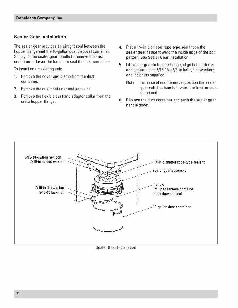
The sealer gear provides an airtight seal between the hopper flange and the 10-gallon dust disposal container. Simply lift the sealer gear handle to remove the dust container or lower the handle to seal the dust container.
To install on an existing unit:
1. Remove the cover and clamp from the dust container.
2. Remove the dust container and set aside.
3. Remove the flexible duct and adapter collar from the unit’s hopper flange.
4. Place 1/4-in diameter rope-type sealant on the sealer gear flange toward the inside edge of the bolt pattern. See Sealer Gear Installation.
5. Lift sealer gear to hopper flange, align bolt patterns, and secure using 5/16-18 x 5/8-in bolts, flat washers, and lock nuts supplied.
Note: For ease of maintenance, position the sealer gear with the handle toward the front or side of the unit.
6. Replace the dust container and push the sealer gear handle down.

Downflo Oval, DFO 1-1 to 3-3
22
Delta P Control
For complete information, see the most current version of the Delta P Installation, Operation, and Maintenance manual.
Description
The Delta P Controller monitors the differential pressure between the clean-air and dirty-air plenums, providing a visual display of the filter condition. When combined with a pulse timer, it manages the pressure drop by turning the cleaning mechanism On and Off at the chosen limits. There are three (3) set points: High Pressure On, Low Pressure Off, and Alarm. The first two, High Pressure On and Low Pressure Off, control the filter cleaning system. The third, Alarm, provides a relay output to activate an external alarm supplied by others.
Operation
Normal
The Delta P Controller monitors the pressure in the clean-air and dirty-air air plenums while the collector is running. The blower draws air through the filters, creating a pressure drop. The Delta P Controller measures the pressure drop and provides a visual display in inches water gauge or metric (SI) collectors of daPa.
Filter Cleaning
When the pressure drop across the filters reaches the High Pressure On setpoint, the controller closes an output relay allowing a timer to trigger the cleaning valves sequentially. When the controller senses that the pressure drop has decreased to the Low Pressure Off setpoint, the relay opens and the cleaning cycle stops. This sequence continues as long as the collector is in use, maintaining the pressure drop within a narrow range.
Alarm
The Alarm setpoint is set to a higher setting than the High Pressure On setpoint used to start the filter cleaning cycle. It indicates situations when the cleaning system cannot reduce the pressure drop due to cleaning system failure, lack of compressed air, or the end of the filter’s useful life. There is a time delay prior to setting the Alarm to prevent nuisance trips. The Delta P Controller also provides an input connection for a remote alarm reset.
Delta P Control Display

23
Donaldson Company, Inc.
rigid caster assembly swivel caster assembly
3/8-16 x 5-inGr2 hex bolt
3/8-in flat washer
3/8-in flat washer
3/8-in lock washer
3/8-16 hex nutremove motorpanel
Caster Assembly
Caster Assembly
The caster assembly includes one rigid and one swivel caster set.
1. Lift unit approximately 24-in with a crane or forklift.
2. Position the swivel caster assembly under the front filter-access end of the unit. Align bolt holes and secure using the 3/8-16 x 5-in bolts, flat washers, lock washers, and hex nuts supplied. See Caster Installation.
3. Remove the lower side motor panel from the unit.
4. Position the rigid caster assembly under the back edge of the unit and fasten as described in Step 2.
5. Replace motor panel and lower unit.
Downflo Oval, DFO 1-1 to 3-3
24
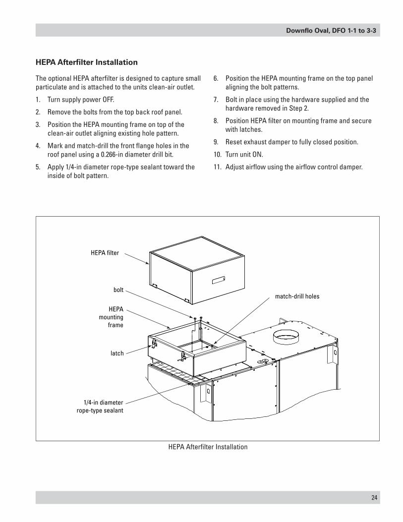
HEPA Afterfilter Installation
The optional HEPA afterfilter is designed to capture small particulate and is attached to the units clean-air outlet.
1. Turn supply power OFF.
2. Remove the bolts from the top back roof panel.
3. Position the HEPA mounting frame on top of the clean-air outlet aligning existing hole pattern.
4. Mark and match-drill the front flange holes in the roof panel using a 0.266-in diameter drill bit.
5. Apply 1/4-in diameter rope-type sealant toward the inside of bolt pattern.
6. Position the HEPA mounting frame on the top panel aligning the bolt patterns.
7. Bolt in place using the hardware supplied and the hardware removed in Step 2.
8. Position HEPA filter on mounting frame and secure with latches.
9. Reset exhaust damper to fully closed position.
10. Turn unit ON.
11. Adjust airflow using the airflow control damper.
1/4-in diameterrope-type sealant
latch
HEPAmounting
frame
HEPA filter
boltmatch-drill holes
HEPA Afterfilter Installation

25
Donaldson Company, Inc.
12
34
remove fourself-threading bolts
match-drill eight 3/8-in
diameter holes
four self-threading bolts
1/4-in diameterrope-typesealant
5/16-18 x 1-in hex bolt5/16-in sealed washer
5/16-in sealed washer5/16-in lock washer
5/16-18 hex nut
Mounting Adapter Installation
Extraction Arm and Adapter Installation
Extraction Arms (Ex-Arms) are designed to carry dust, fume, and mist away from the worker’s breathing zone. The operator positions the hood 8- to 12-inches above the work area. Contaminated air is drawn into the hood, through the Ex-Arm and into the dirty-air plenum of the unit where it is filtered and exhausted.
Mounting Adapter
1. Remove the four self-threading bolts from the roof panel. See Mounting Adapter Installation.
2. Place the mounting adapter on the roof panel aligning the bolt holes from the bolts removed in Step 1 with the bolt pattern on the mounting adapter.
Note: The bolt pattern of the mounting adapter is not symmetrical. If the bolt patterns do not line up, turn the mounting adapter 180°.
3. Match-drill eight 3/8-in holes in the roof panel using the mounting adapter as a guide.
4. Remove the mounting adapter and set aside.
5. Place 1/4-in diameter, rope-type sealant on the roof panel toward the inside of the bolt pattern.
6. Place mounting adapter on the roof panel and align bolt patterns.
7. Remove the filter-access cover and filters to access the inside of the unit when attaching the mounting adapter.
8. Secure mounting adapter to roof panel using the four self-threading bolts removed in Step 1 and the 5/16-18 x 1-in bolts, sealed washers, lock washers, and hex nuts provided. See Mounting Adapter Installation.
9. Tighten all hardware securely.
10. Replace filter and filter access cover.
Downflo Oval, DFO 1-1 to 3-3
26
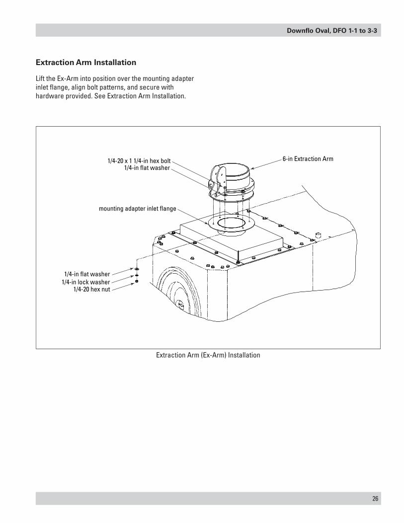
6-in Extraction Arm1/4-20 x 1 1/4-in hex bolt1/4-in flat washer
1/4-in flat washer1/4-in lock washer
1/4-20 hex nut
mounting adapter inlet flange
Extraction Arm (Ex-Arm) Installation
Extraction Arm Installation
Lift the Ex-Arm into position over the mounting adapter inlet flange, align bolt patterns, and secure with hardware provided. See Extraction Arm Installation.
27
Donaldson Company, Inc.
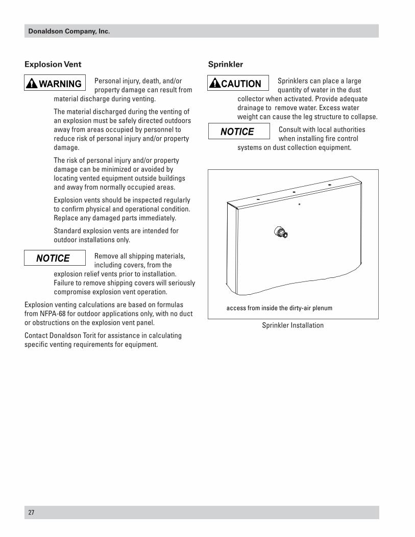
access from inside the dirty-air plenum
Sprinkler Installation
Explosion Vent
Personal injury, death, and/or property damage can result from
material discharge during venting.
The material discharged during the venting of an explosion must be safely directed outdoors away from areas occupied by personnel to reduce risk of personal injury and/or property damage.
The risk of personal injury and/or property damage can be minimized or avoided by locating vented equipment outside buildings and away from normally occupied areas.
Explosion vents should be inspected regularly to confirm physical and operational condition. Replace any damaged parts immediately.
Standard explosion vents are intended for outdoor installations only.
Remove all shipping materials, including covers, from the
explosion relief vents prior to installation. Failure to remove shipping covers will seriously compromise explosion vent operation.
Explosion venting calculations are based on formulas from NFPA-68 for outdoor applications only, with no duct or obstructions on the explosion vent panel.
Contact Donaldson Torit for assistance in calculating specific venting requirements for equipment.
Sprinkler
Sprinklers can place a large quantity of water in the dust
collector when activated. Provide adequate drainage to remove water. Excess water weight can cause the leg structure to collapse.
Consult with local authorities when installing fire control
systems on dust collection equipment.

Downflo Oval, DFO 1-1 to 3-3
28
Problem Probable Cause Remedy
Fan blower and motor do not start
Improper motor wire size Rewire using the correct wire gauge as specified by national and local codes.
Not wired correctly Check and correct motor wiring for supply voltage. See motor manufacturer's wiring diagram. Follow wiring diagram and the National Electric Code.
Collector not wired for available voltage
Correct wiring for proper supply voltage.
Input circuit down Check power supply to motor circuit on all leads.Electrical supply circuit down Check power supply circuit for proper voltage.
Check for fuse or circuit breaker fault. Replace as necessary.
Damaged motor Replace damaged motor.Fan blower and motor start, but do not stay running
Incorrect motor starter installed Check for proper motor starter and replace if necessary.
Access doors are open or not closed tight
Close and tighten access doors. See Filter Installation.
Hopper discharge open Check that dust container is installed and properly sealed.
Damper control not adjusted properly
Check airflow in duct. Adjust damper control until proper airflow is achieved and the blower motor’s amp draw is within the manufacturer’s rated amps.
Electrical circuit overload Check that the power supply circuit has sufficient power to run all equipment.
Clean-air outlet discharging dust
Filters not installed correctly See Filter Installation.
Filter damage, dents in the end caps, gasket damage, or holes in media
Replace filters as necessary. Use only genuine Donaldson replacement parts. See Filter Installation.
Access cover(s) loose Tighten access doors securely. See Filter Installation.
Insufficient airflow Fan rotation backwards Proper fan rotation is clockwise from the top of the collector. The fan can be viewed through the back of the motor. See Preliminary Start-Up Check.
Access doors open or not closed tight
Check that all access doors are in place and secured. Check that the hopper discharge opening is sealed and that dust container is installed correctly.
Fan exhaust area restricted Check fan exhaust area for obstructions. Remove material or debris. Adjust damper flow control.
Filters need replacement Remove and replace using genuine Donaldson replacement filters. See Filter Removal and Installation.
Troubleshooting
29
Donaldson Company, Inc.
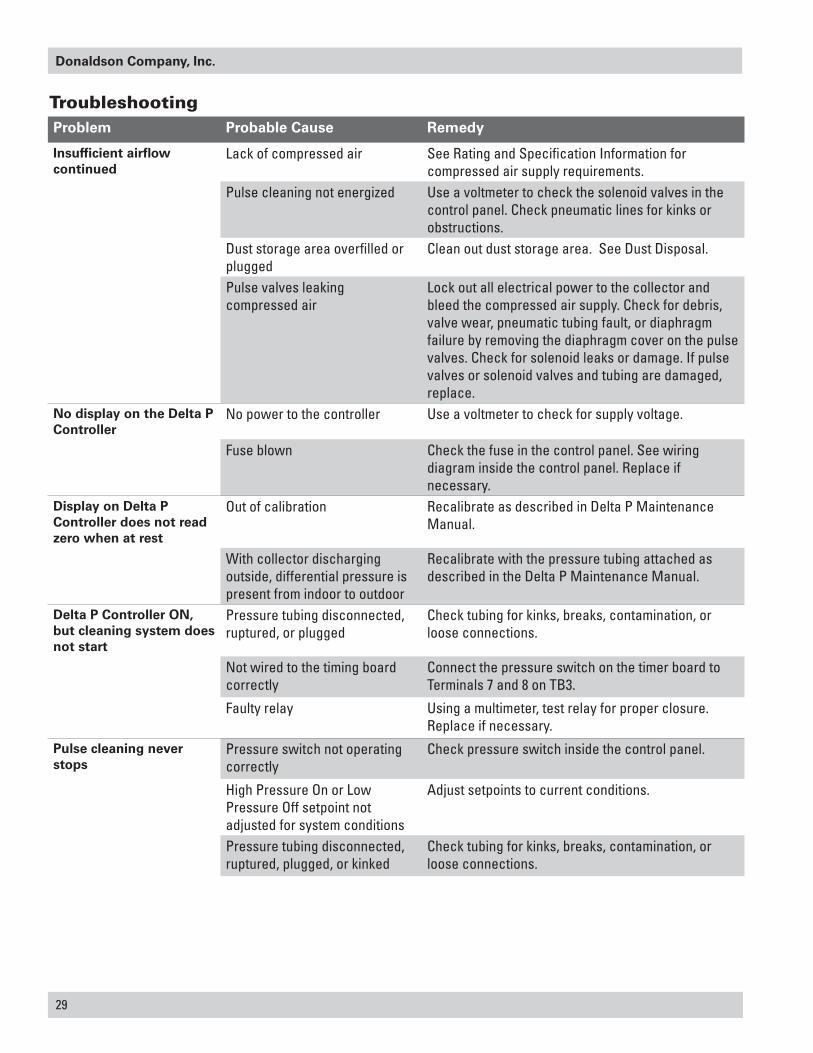
Problem Probable Cause Remedy
Insufficient airflow continued
Lack of compressed air See Rating and Specification Information for compressed air supply requirements.
Pulse cleaning not energized Use a voltmeter to check the solenoid valves in the control panel. Check pneumatic lines for kinks or obstructions.
Dust storage area overfilled or plugged
Clean out dust storage area. See Dust Disposal.
Pulse valves leaking compressed air
Lock out all electrical power to the collector and bleed the compressed air supply. Check for debris, valve wear, pneumatic tubing fault, or diaphragm failure by removing the diaphragm cover on the pulse valves. Check for solenoid leaks or damage. If pulse valves or solenoid valves and tubing are damaged, replace.
No display on the Delta P Controller
No power to the controller Use a voltmeter to check for supply voltage.
Fuse blown Check the fuse in the control panel. See wiring diagram inside the control panel. Replace if necessary.
Display on Delta P Controller does not read zero when at rest
Out of calibration Recalibrate as described in Delta P Maintenance Manual.
With collector discharging outside, differential pressure is present from indoor to outdoor
Recalibrate with the pressure tubing attached as described in the Delta P Maintenance Manual.
Delta P Controller ON, but cleaning system does not start
Pressure tubing disconnected, ruptured, or plugged
Check tubing for kinks, breaks, contamination, or loose connections.
Not wired to the timing board correctly
Connect the pressure switch on the timer board to Terminals 7 and 8 on TB3.
Faulty relay Using a multimeter, test relay for proper closure. Replace if necessary.
Pulse cleaning never stops
Pressure switch not operating correctly
Check pressure switch inside the control panel.
High Pressure On or Low Pressure Off setpoint not adjusted for system conditions
Adjust setpoints to current conditions.
Pressure tubing disconnected, ruptured, plugged, or kinked
Check tubing for kinks, breaks, contamination, or loose connections.
Troubleshooting

Downflo Oval, DFO 1-1 to 3-3
30
Problem Probable Cause Remedy
Alarm light is ON Alarm setpoint too low Adjust to a higher value.Excess pressure drop Check cleaning system and compressed air supply.
Replace filters if filters do not clean down.Pressure tubing disconnected, ruptured, plugged, or kinked
Check tubing for kinks, breaks, contamination, or loose connections.
Delta P arrow keys to not work
Improper operation Press and hold one of the three setpoint keys to use arrow keys.
Programming keys disabled Remove the Program Disable jumper from Terminals 3 and 4 on TB2.
Cleaning light is ON, but cleaning system not functioning
Improper wiring Check wiring between the Delta P Control and the timer board, and between the timer board and solenoid valve coils.
Defective solenoids Check all solenoid coils for proper operation.Timer board not powered Check power ON light on timer board's LED display.
If not illuminated, check the supply voltage to the timer board. Check the fuse on the timer board. Replace if necessary.
Timer board defective If LED is illuminated, observe the output display. Install a temporary jumper across the pressure switch terminals. Output levels should flash in sequence. Check output using a multimeter set to 150-Volt AC range. Measure from SOL COM to a solenoid output. The needle will deflect when LED flashes for that output if voltage is present. If LED's do not flash, or if no voltage is present at output terminals during flash, replace the board.
31
Donaldson Company, Inc.
Service Notes
Date Service Performed Notes


Donaldson Company, Inc. is the leading designer and manufacturer of dust, mist, and fume collection equipment used to control industrial-air pollutants. Our equipment is designed to help reduce occupational hazards, lengthen machine life, reduce in-plant maintenance requirements, and improve product quality.
Parts and Service
For genuine Donaldson replacement filters and parts, call the Parts Express Line. For faster service, have unit’s model and serial number, quantity, part number, and description available.
Donaldson Company, Inc.ToritPO Box 1299Minneapolis, MN 55440-1299U.S.A.
The Donaldson Torit Warranty
Donaldson warrants to the original purchaser that the major structural components of the goods will be free from defects in materials and workmanship for ten (10) years from the date of shipment, if properly installed, maintained and operated under normal conditions. Donaldson warrants all other Donaldson built components and accessories including Donaldson Airlocks, TBI Fans, TRB Fans, Fume Collector products and Donaldson built Afterfilters for twelve (12) months from date of shipment. Donaldson warrants Donaldson built filter elements to be free from defects in materials and workmanship for eighteen (18) months from date of shipment. Donaldson does not warrant against damages due to corrosion, abrasion, normal wear and tear, product modification, or product misapplication. Donaldson also makes no warranty whatsoever as to any goods manufactured or supplied by others including electric motors, fans and control components. After Donaldson has been given adequate opportunity to remedy any defects in material or workmanship, Donaldson retains the sole option to accept return of the goods, with freight paid by the purchaser, and to refund the purchase price for the goods after confirming the goods are returned undamaged and in usable condition. Such a refund will be in the full extent of Donaldson’s liability. Donaldson shall not be liable for any other costs, expenses or damages whether direct, indirect, special, incidental, consequential or otherwise. The terms of this warranty may be modified only by a special warranty document signed by a Director, General Manager or Vice President of Donaldson. To ensure proper operational performance of the equipment, use only genuine Donaldson replacement parts. THERE EXIST NO OTHER REPRESENTATIONS, WARRANTIES OR GUARANTEES EXCEPT AS STATED IN THIS PARAGRAPH AND ALL OTHER WARRANTIES INCLUDING MERCHANTABILITY AND FITNESS FOR A PARTICULAR PURPOSE, WHETHER EXPRESS OR IMPLIED ARE HEREBY EXPRESSLY EXCLUDED AND DISCLAIMED.
800-365-1331 USA 800-343-3639 within Mexico+52 (449) 300 24 42 Latin America
[email protected] donaldsontorit.com
© 2002 Donaldson Company, Inc. IOM AD3092901 (ENG), Revision 10Printed in USA July 2016