Embed Size (px)
Citation preview
PA-RISC 1.1 Architecture andInstruction Set Reference Manual
HP Part Number: 09740-90039
Printed in U.S.A. February 1994
Third Edition
NoticeThe information contained in this document is subject to change without notice.
HEWLETT-PACKARD MAKES NO WARRANTY OF ANY KIND WITH REGARD TO THISMATERIAL, INCLUDING, BUT NOT LIMITED TO, THE IMPLIED WARRANTIES OFMERCHANTABILITY AND FITNESS FOR A PARTICULAR PURPOSE.
Hewlett-Packard shall not be liable for errors contained herein or for incidental or consequentialdamages in connection with furnishing, performance, or use of this material.
Hewlett-Packard assumes no responsibility for the use or reliability of its software on equipment that isnot furnished by Hewlett-Packard.
This document contains proprietary information which is protected by copyright. All rights arereserved. No part of this document may be photocopied, reproduced, or translated to another languagewithout the prior written consent of Hewlett-Packard Company.
Copyright © 1986 – 1994 by HEWLETT-PACKARD COMPANY
Printing HistoryThe printing date will change when a new edition is printed. The manual part number will change whenextensive changes are made.
First Edition . . . . . . . . . . . . . . . . . . . . November 1990Second Edition. . . . . . . . . . . . . . . . . . . September 1992Third Edition . . . . . . . . . . . . . . . . . . . . February 1994
iiiPA-RISC 1.1 Architecture Contents
Contents
Contents . . . . . . . . . . . . . . . . . . . . . . . . . . . . . . . . . . . . . . . . . . . . . . . iiiPreface. . . . . . . . . . . . . . . . . . . . . . . . . . . . . . . . . . . . . . . . . . . . . . . . ix
1 Overview . . . . . . . . . . . . . . . . . . . . . . . . . . . . . . . . . . . . . . . . . . . . . 1-1Introduction. . . . . . . . . . . . . . . . . . . . . . . . . . . . . . . . . . . . . . . . . . 1-1System Features . . . . . . . . . . . . . . . . . . . . . . . . . . . . . . . . . . . . . . . 1-2PA-RISC 1.1 Enhancements . . . . . . . . . . . . . . . . . . . . . . . . . . . . . . . . . 1-2System Organization . . . . . . . . . . . . . . . . . . . . . . . . . . . . . . . . . . . . . 1-4
2 System Organization . . . . . . . . . . . . . . . . . . . . . . . . . . . . . . . . . . . . . . . 2-1Introduction. . . . . . . . . . . . . . . . . . . . . . . . . . . . . . . . . . . . . . . . . . 2-1Memory and I/O Addressing . . . . . . . . . . . . . . . . . . . . . . . . . . . . . . . . . 2-2Byte Ordering (Big Endian/Little Endian) . . . . . . . . . . . . . . . . . . . . . . . . . . 2-3Levels of PA-RISC. . . . . . . . . . . . . . . . . . . . . . . . . . . . . . . . . . . . . . 2-5Data Types . . . . . . . . . . . . . . . . . . . . . . . . . . . . . . . . . . . . . . . . . . 2-5Processing Resources. . . . . . . . . . . . . . . . . . . . . . . . . . . . . . . . . . . . . 2-7
3 Addressing and Access Control . . . . . . . . . . . . . . . . . . . . . . . . . . . . . . . . . . 3-1Introduction. . . . . . . . . . . . . . . . . . . . . . . . . . . . . . . . . . . . . . . . . . 3-1Pointers and Address Specification . . . . . . . . . . . . . . . . . . . . . . . . . . . . . 3-2Address Resolution and the TLB. . . . . . . . . . . . . . . . . . . . . . . . . . . . . . . 3-3Access Control . . . . . . . . . . . . . . . . . . . . . . . . . . . . . . . . . . . . . . . .3-10Page Table Structure . . . . . . . . . . . . . . . . . . . . . . . . . . . . . . . . . . . . .3-14Caches . . . . . . . . . . . . . . . . . . . . . . . . . . . . . . . . . . . . . . . . . . . .3-15The Synchronization Primitive . . . . . . . . . . . . . . . . . . . . . . . . . . . . . . . .3-16Cache Coherence with I/O . . . . . . . . . . . . . . . . . . . . . . . . . . . . . . . . . .3-17Cache Coherence in Multiprocessor Systems . . . . . . . . . . . . . . . . . . . . . . . .3-17TLB Coherence in Multiprocessor Systems . . . . . . . . . . . . . . . . . . . . . . . . .3-18TLB Operation Requirements . . . . . . . . . . . . . . . . . . . . . . . . . . . . . . . .3-18Data Cache Move-In . . . . . . . . . . . . . . . . . . . . . . . . . . . . . . . . . . . . .3-21Instruction Cache Move-In . . . . . . . . . . . . . . . . . . . . . . . . . . . . . . . . . .3-22
4 Flow Control and Interruptions . . . . . . . . . . . . . . . . . . . . . . . . . . . . . . . . . . 4-1Introduction. . . . . . . . . . . . . . . . . . . . . . . . . . . . . . . . . . . . . . . . . . 4-1Instruction Execution. . . . . . . . . . . . . . . . . . . . . . . . . . . . . . . . . . . . . 4-1Atomicity of Storage Accesses. . . . . . . . . . . . . . . . . . . . . . . . . . . . . . . . 4-3Ordering of Accesses. . . . . . . . . . . . . . . . . . . . . . . . . . . . . . . . . . . . . 4-3Completion of Accesses . . . . . . . . . . . . . . . . . . . . . . . . . . . . . . . . . . . 4-5Instruction Pipelining. . . . . . . . . . . . . . . . . . . . . . . . . . . . . . . . . . . . . 4-6Nullification . . . . . . . . . . . . . . . . . . . . . . . . . . . . . . . . . . . . . . . . . 4-7Branching. . . . . . . . . . . . . . . . . . . . . . . . . . . . . . . . . . . . . . . . . . . 4-7Interruptions . . . . . . . . . . . . . . . . . . . . . . . . . . . . . . . . . . . . . . . . .4-13
5 Instruction Set . . . . . . . . . . . . . . . . . . . . . . . . . . . . . . . . . . . . . . . . . . . 5-1Introduction. . . . . . . . . . . . . . . . . . . . . . . . . . . . . . . . . . . . . . . . . . 5-1Undefined and Illegal Instructions . . . . . . . . . . . . . . . . . . . . . . . . . . . . . . 5-1Reserved Instruction Fields . . . . . . . . . . . . . . . . . . . . . . . . . . . . . . . . . 5-2Reserved Values of an Instruction Field . . . . . . . . . . . . . . . . . . . . . . . . . . . 5-2
iv Contents PA-RISC 1.1 Architecture
Null Instructions. . . . . . . . . . . . . . . . . . . . . . . . . . . . . . . . . . . . . . . . 5-2Conditions and Control Flow . . . . . . . . . . . . . . . . . . . . . . . . . . . . . . . . . 5-2Instruction Notations . . . . . . . . . . . . . . . . . . . . . . . . . . . . . . . . . . . . . 5-7Instruction Descriptions. . . . . . . . . . . . . . . . . . . . . . . . . . . . . . . . . . .5-14Memory Reference Instructions. . . . . . . . . . . . . . . . . . . . . . . . . . . . . . . 5-15Immediate Instructions . . . . . . . . . . . . . . . . . . . . . . . . . . . . . . . . . . .5-54Branch Instructions . . . . . . . . . . . . . . . . . . . . . . . . . . . . . . . . . . . . . 5-58Computation Instructions . . . . . . . . . . . . . . . . . . . . . . . . . . . . . . . . . . 5-81System Control Instructions. . . . . . . . . . . . . . . . . . . . . . . . . . . . . . . . 5-136Assist Instructions. . . . . . . . . . . . . . . . . . . . . . . . . . . . . . . . . . . . . 5-176
6 Floating-point Coprocessor . . . . . . . . . . . . . . . . . . . . . . . . . . . . . . . . . . . . 6-1Introduction . . . . . . . . . . . . . . . . . . . . . . . . . . . . . . . . . . . . . . . . . . 6-1Data Registers . . . . . . . . . . . . . . . . . . . . . . . . . . . . . . . . . . . . . . . . . 6-5Data Formats . . . . . . . . . . . . . . . . . . . . . . . . . . . . . . . . . . . . . . . . . 6-6Status Register . . . . . . . . . . . . . . . . . . . . . . . . . . . . . . . . . . . . . . . . 6-9Instruction Set . . . . . . . . . . . . . . . . . . . . . . . . . . . . . . . . . . . . . . . . 6-12Exception Registers . . . . . . . . . . . . . . . . . . . . . . . . . . . . . . . . . . . . . 6-23Interruptions and Exceptions . . . . . . . . . . . . . . . . . . . . . . . . . . . . . . . . 6-26Saving and Restoring State . . . . . . . . . . . . . . . . . . . . . . . . . . . . . . . . . 6-35Instruction Set Description . . . . . . . . . . . . . . . . . . . . . . . . . . . . . . . . . 6-36
7 Performance Monitor Coprocessor . . . . . . . . . . . . . . . . . . . . . . . . . . . . . . . . 7-1Introduction . . . . . . . . . . . . . . . . . . . . . . . . . . . . . . . . . . . . . . . . . . 7-1The Instruction Set . . . . . . . . . . . . . . . . . . . . . . . . . . . . . . . . . . . . . . 7-1Interruptions. . . . . . . . . . . . . . . . . . . . . . . . . . . . . . . . . . . . . . . . . . 7-1Monitor Units . . . . . . . . . . . . . . . . . . . . . . . . . . . . . . . . . . . . . . . . . 7-2Instruction Set Description . . . . . . . . . . . . . . . . . . . . . . . . . . . . . . . . . . 7-2
8 Debug Special Function Unit . . . . . . . . . . . . . . . . . . . . . . . . . . . . . . . . . . . 8-1Introduction . . . . . . . . . . . . . . . . . . . . . . . . . . . . . . . . . . . . . . . . . . 8-1Debug Registers . . . . . . . . . . . . . . . . . . . . . . . . . . . . . . . . . . . . . . . . 8-1The Instruction Set . . . . . . . . . . . . . . . . . . . . . . . . . . . . . . . . . . . . . . 8-3Interruptions. . . . . . . . . . . . . . . . . . . . . . . . . . . . . . . . . . . . . . . . . . 8-4Instruction Set Description . . . . . . . . . . . . . . . . . . . . . . . . . . . . . . . . . . 8-5
A Glossary . . . . . . . . . . . . . . . . . . . . . . . . . . . . . . . . . . . . . . . . . . . . . A-1B Instruction Index . . . . . . . . . . . . . . . . . . . . . . . . . . . . . . . . . . . . . . . . . .B-1C Instruction Formats . . . . . . . . . . . . . . . . . . . . . . . . . . . . . . . . . . . . . . . .C-1D Operation Codes . . . . . . . . . . . . . . . . . . . . . . . . . . . . . . . . . . . . . . . . . D-1
Major Opcode Assignments. . . . . . . . . . . . . . . . . . . . . . . . . . . . . . . . . D-1Opcode Extension Assignments . . . . . . . . . . . . . . . . . . . . . . . . . . . . . . D-3
E Level 0 Summary . . . . . . . . . . . . . . . . . . . . . . . . . . . . . . . . . . . . . . . . .E-1I Index . . . . . . . . . . . . . . . . . . . . . . . . . . . . . . . . . . . . . . . . . . . . . . . . I-1
vPA-RISC 1.1 Architecture
Figures
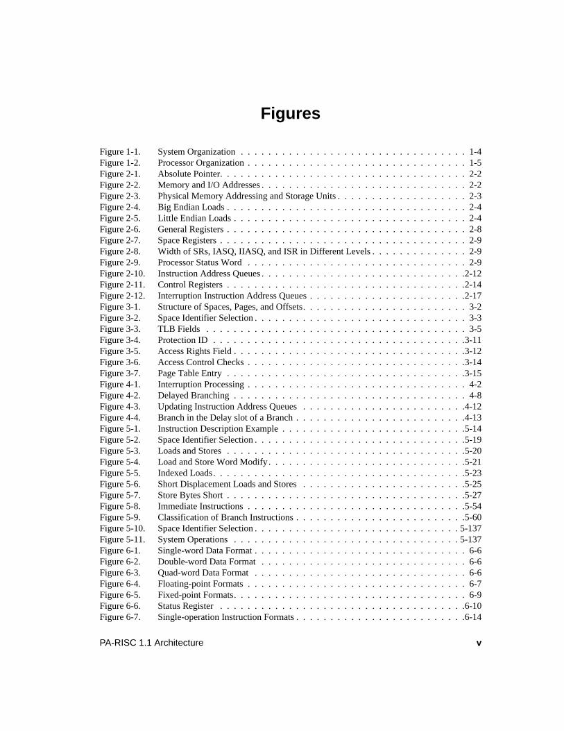
Figure 1-1. System Organization . . . . . . . . . . . . . . . . . . . . . . . . . . . . . . . . . 1-4Figure 1-2. Processor Organization . . . . . . . . . . . . . . . . . . . . . . . . . . . . . . . . 1-5Figure 2-1. Absolute Pointer. . . . . . . . . . . . . . . . . . . . . . . . . . . . . . . . . . . . 2-2Figure 2-2. Memory and I/O Addresses . . . . . . . . . . . . . . . . . . . . . . . . . . . . . . 2-2Figure 2-3. Physical Memory Addressing and Storage Units . . . . . . . . . . . . . . . . . . . 2-3Figure 2-4. Big Endian Loads . . . . . . . . . . . . . . . . . . . . . . . . . . . . . . . . . . . 2-4Figure 2-5. Little Endian Loads . . . . . . . . . . . . . . . . . . . . . . . . . . . . . . . . . . 2-4Figure 2-6. General Registers . . . . . . . . . . . . . . . . . . . . . . . . . . . . . . . . . . . 2-8Figure 2-7. Space Registers . . . . . . . . . . . . . . . . . . . . . . . . . . . . . . . . . . . . 2-9Figure 2-8. Width of SRs, IASQ, IIASQ, and ISR in Different Levels . . . . . . . . . . . . . . 2-9Figure 2-9. Processor Status Word . . . . . . . . . . . . . . . . . . . . . . . . . . . . . . . . 2-9Figure 2-10. Instruction Address Queues . . . . . . . . . . . . . . . . . . . . . . . . . . . . . .2-12Figure 2-11. Control Registers . . . . . . . . . . . . . . . . . . . . . . . . . . . . . . . . . . .2-14Figure 2-12. Interruption Instruction Address Queues . . . . . . . . . . . . . . . . . . . . . . .2-17Figure 3-1. Structure of Spaces, Pages, and Offsets. . . . . . . . . . . . . . . . . . . . . . . . 3-2Figure 3-2. Space Identifier Selection . . . . . . . . . . . . . . . . . . . . . . . . . . . . . . . 3-3Figure 3-3. TLB Fields . . . . . . . . . . . . . . . . . . . . . . . . . . . . . . . . . . . . . . 3-5Figure 3-4. Protection ID . . . . . . . . . . . . . . . . . . . . . . . . . . . . . . . . . . . . .3-11Figure 3-5. Access Rights Field . . . . . . . . . . . . . . . . . . . . . . . . . . . . . . . . . .3-12Figure 3-6. Access Control Checks . . . . . . . . . . . . . . . . . . . . . . . . . . . . . . . .3-14Figure 3-7. Page Table Entry . . . . . . . . . . . . . . . . . . . . . . . . . . . . . . . . . . .3-15Figure 4-1. Interruption Processing . . . . . . . . . . . . . . . . . . . . . . . . . . . . . . . . 4-2Figure 4-2. Delayed Branching . . . . . . . . . . . . . . . . . . . . . . . . . . . . . . . . . . 4-8Figure 4-3. Updating Instruction Address Queues . . . . . . . . . . . . . . . . . . . . . . . .4-12Figure 4-4. Branch in the Delay slot of a Branch . . . . . . . . . . . . . . . . . . . . . . . . .4-13Figure 5-1. Instruction Description Example . . . . . . . . . . . . . . . . . . . . . . . . . . .5-14Figure 5-2. Space Identifier Selection . . . . . . . . . . . . . . . . . . . . . . . . . . . . . . .5-19Figure 5-3. Loads and Stores . . . . . . . . . . . . . . . . . . . . . . . . . . . . . . . . . . .5-20Figure 5-4. Load and Store Word Modify . . . . . . . . . . . . . . . . . . . . . . . . . . . . .5-21Figure 5-5. Indexed Loads. . . . . . . . . . . . . . . . . . . . . . . . . . . . . . . . . . . . .5-23Figure 5-6. Short Displacement Loads and Stores . . . . . . . . . . . . . . . . . . . . . . . .5-25Figure 5-7. Store Bytes Short . . . . . . . . . . . . . . . . . . . . . . . . . . . . . . . . . . .5-27Figure 5-8. Immediate Instructions . . . . . . . . . . . . . . . . . . . . . . . . . . . . . . . .5-54Figure 5-9. Classification of Branch Instructions . . . . . . . . . . . . . . . . . . . . . . . . .5-60Figure 5-10. Space Identifier Selection . . . . . . . . . . . . . . . . . . . . . . . . . . . . . . 5-137Figure 5-11. System Operations . . . . . . . . . . . . . . . . . . . . . . . . . . . . . . . . . 5-137Figure 6-1. Single-word Data Format . . . . . . . . . . . . . . . . . . . . . . . . . . . . . . . 6-6Figure 6-2. Double-word Data Format . . . . . . . . . . . . . . . . . . . . . . . . . . . . . . 6-6Figure 6-3. Quad-word Data Format . . . . . . . . . . . . . . . . . . . . . . . . . . . . . . . 6-6Figure 6-4. Floating-point Formats . . . . . . . . . . . . . . . . . . . . . . . . . . . . . . . . 6-7Figure 6-5. Fixed-point Formats. . . . . . . . . . . . . . . . . . . . . . . . . . . . . . . . . . 6-9Figure 6-6. Status Register . . . . . . . . . . . . . . . . . . . . . . . . . . . . . . . . . . . .6-10Figure 6-7. Single-operation Instruction Formats . . . . . . . . . . . . . . . . . . . . . . . . .6-14
vi PA-RISC 1.1 Architecture
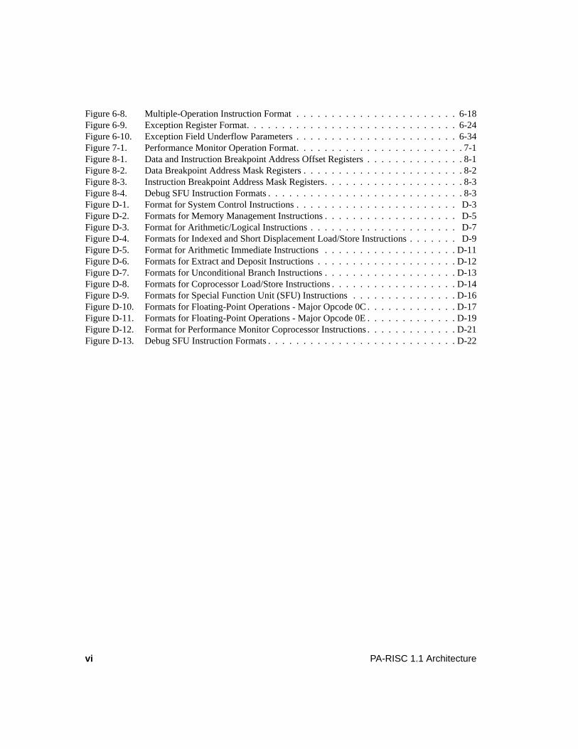
Figure 6-8. Multiple-Operation Instruction Format . . . . . . . . . . . . . . . . . . . . . . . 6-18Figure 6-9. Exception Register Format. . . . . . . . . . . . . . . . . . . . . . . . . . . . . . 6-24Figure 6-10. Exception Field Underflow Parameters . . . . . . . . . . . . . . . . . . . . . . . 6-34Figure 7-1. Performance Monitor Operation Format. . . . . . . . . . . . . . . . . . . . . . . . 7-1Figure 8-1. Data and Instruction Breakpoint Address Offset Registers . . . . . . . . . . . . . . 8-1Figure 8-2. Data Breakpoint Address Mask Registers . . . . . . . . . . . . . . . . . . . . . . . 8-2Figure 8-3. Instruction Breakpoint Address Mask Registers. . . . . . . . . . . . . . . . . . . . 8-3Figure 8-4. Debug SFU Instruction Formats . . . . . . . . . . . . . . . . . . . . . . . . . . . . 8-3Figure D-1. Format for System Control Instructions . . . . . . . . . . . . . . . . . . . . . . . D-3Figure D-2. Formats for Memory Management Instructions . . . . . . . . . . . . . . . . . . . D-5Figure D-3. Format for Arithmetic/Logical Instructions . . . . . . . . . . . . . . . . . . . . . D-7Figure D-4. Formats for Indexed and Short Displacement Load/Store Instructions . . . . . . . D-9Figure D-5. Format for Arithmetic Immediate Instructions . . . . . . . . . . . . . . . . . . . D-11Figure D-6. Formats for Extract and Deposit Instructions . . . . . . . . . . . . . . . . . . . . D-12Figure D-7. Formats for Unconditional Branch Instructions . . . . . . . . . . . . . . . . . . . D-13Figure D-8. Formats for Coprocessor Load/Store Instructions . . . . . . . . . . . . . . . . . . D-14Figure D-9. Formats for Special Function Unit (SFU) Instructions . . . . . . . . . . . . . . . D-16Figure D-10. Formats for Floating-Point Operations - Major Opcode 0C . . . . . . . . . . . . . D-17Figure D-11. Formats for Floating-Point Operations - Major Opcode 0E . . . . . . . . . . . . . D-19Figure D-12. Format for Performance Monitor Coprocessor Instructions . . . . . . . . . . . . . D-21Figure D-13. Debug SFU Instruction Formats . . . . . . . . . . . . . . . . . . . . . . . . . . . D-22
viiPA-RISC 1.1 Architecture
Tables
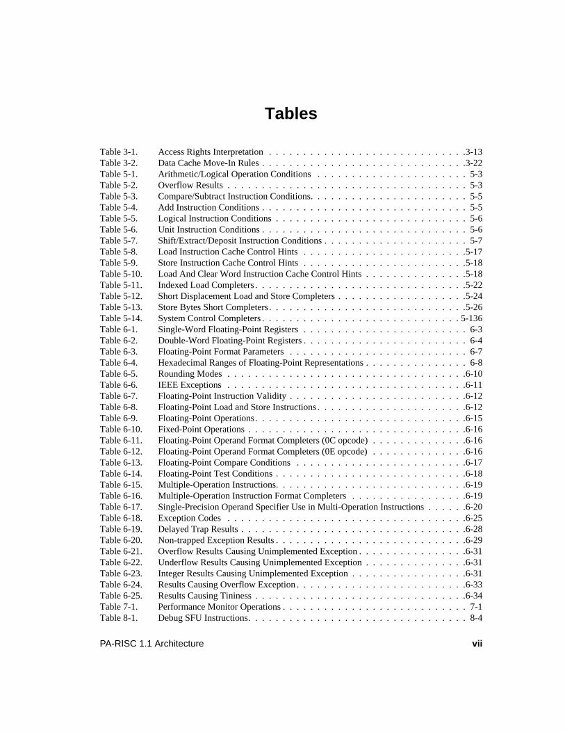
Table 3-1. Access Rights Interpretation . . . . . . . . . . . . . . . . . . . . . . . . . . . . .3-13Table 3-2. Data Cache Move-In Rules . . . . . . . . . . . . . . . . . . . . . . . . . . . . . .3-22Table 5-1. Arithmetic/Logical Operation Conditions . . . . . . . . . . . . . . . . . . . . . . 5-3Table 5-2. Overflow Results . . . . . . . . . . . . . . . . . . . . . . . . . . . . . . . . . . . 5-3Table 5-3. Compare/Subtract Instruction Conditions. . . . . . . . . . . . . . . . . . . . . . . 5-5Table 5-4. Add Instruction Conditions . . . . . . . . . . . . . . . . . . . . . . . . . . . . . . 5-5Table 5-5. Logical Instruction Conditions . . . . . . . . . . . . . . . . . . . . . . . . . . . . 5-6Table 5-6. Unit Instruction Conditions . . . . . . . . . . . . . . . . . . . . . . . . . . . . . . 5-6Table 5-7. Shift/Extract/Deposit Instruction Conditions . . . . . . . . . . . . . . . . . . . . . 5-7Table 5-8. Load Instruction Cache Control Hints . . . . . . . . . . . . . . . . . . . . . . . .5-17Table 5-9. Store Instruction Cache Control Hints . . . . . . . . . . . . . . . . . . . . . . . .5-18Table 5-10. Load And Clear Word Instruction Cache Control Hints . . . . . . . . . . . . . . .5-18Table 5-11. Indexed Load Completers . . . . . . . . . . . . . . . . . . . . . . . . . . . . . . .5-22Table 5-12. Short Displacement Load and Store Completers . . . . . . . . . . . . . . . . . . .5-24Table 5-13. Store Bytes Short Completers. . . . . . . . . . . . . . . . . . . . . . . . . . . . .5-26Table 5-14. System Control Completers . . . . . . . . . . . . . . . . . . . . . . . . . . . . . 5-136Table 6-1. Single-Word Floating-Point Registers . . . . . . . . . . . . . . . . . . . . . . . . 6-3Table 6-2. Double-Word Floating-Point Registers . . . . . . . . . . . . . . . . . . . . . . . . 6-4Table 6-3. Floating-Point Format Parameters . . . . . . . . . . . . . . . . . . . . . . . . . . 6-7Table 6-4. Hexadecimal Ranges of Floating-Point Representations . . . . . . . . . . . . . . . 6-8Table 6-5. Rounding Modes . . . . . . . . . . . . . . . . . . . . . . . . . . . . . . . . . . .6-10Table 6-6. IEEE Exceptions . . . . . . . . . . . . . . . . . . . . . . . . . . . . . . . . . . .6-11Table 6-7. Floating-Point Instruction Validity . . . . . . . . . . . . . . . . . . . . . . . . . .6-12Table 6-8. Floating-Point Load and Store Instructions . . . . . . . . . . . . . . . . . . . . . .6-12Table 6-9. Floating-Point Operations. . . . . . . . . . . . . . . . . . . . . . . . . . . . . . .6-15Table 6-10. Fixed-Point Operations . . . . . . . . . . . . . . . . . . . . . . . . . . . . . . . .6-16Table 6-11. Floating-Point Operand Format Completers (0C opcode) . . . . . . . . . . . . . .6-16Table 6-12. Floating-Point Operand Format Completers (0E opcode) . . . . . . . . . . . . . .6-16Table 6-13. Floating-Point Compare Conditions . . . . . . . . . . . . . . . . . . . . . . . . .6-17Table 6-14. Floating-Point Test Conditions . . . . . . . . . . . . . . . . . . . . . . . . . . . .6-18Table 6-15. Multiple-Operation Instructions. . . . . . . . . . . . . . . . . . . . . . . . . . . .6-19Table 6-16. Multiple-Operation Instruction Format Completers . . . . . . . . . . . . . . . . .6-19Table 6-17. Single-Precision Operand Specifier Use in Multi-Operation Instructions . . . . . .6-20Table 6-18. Exception Codes . . . . . . . . . . . . . . . . . . . . . . . . . . . . . . . . . . .6-25Table 6-19. Delayed Trap Results . . . . . . . . . . . . . . . . . . . . . . . . . . . . . . . . .6-28Table 6-20. Non-trapped Exception Results . . . . . . . . . . . . . . . . . . . . . . . . . . . .6-29Table 6-21. Overflow Results Causing Unimplemented Exception . . . . . . . . . . . . . . . .6-31Table 6-22. Underflow Results Causing Unimplemented Exception . . . . . . . . . . . . . . .6-31Table 6-23. Integer Results Causing Unimplemented Exception . . . . . . . . . . . . . . . . .6-31Table 6-24. Results Causing Overflow Exception . . . . . . . . . . . . . . . . . . . . . . . . .6-33Table 6-25. Results Causing Tininess . . . . . . . . . . . . . . . . . . . . . . . . . . . . . . .6-34Table 7-1. Performance Monitor Operations . . . . . . . . . . . . . . . . . . . . . . . . . . . 7-1Table 8-1. Debug SFU Instructions. . . . . . . . . . . . . . . . . . . . . . . . . . . . . . . . 8-4
viii PA-RISC 1.1 Architecture
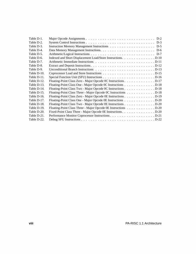
Table D-1. Major Opcode Assignments . . . . . . . . . . . . . . . . . . . . . . . . . . . . . D-2Table D-2. System Control Instructions . . . . . . . . . . . . . . . . . . . . . . . . . . . . . D-3Table D-3. Instruction Memory Management Instructions . . . . . . . . . . . . . . . . . . . D-5Table D-4. Data Memory Management Instructions. . . . . . . . . . . . . . . . . . . . . . . D-6Table D-5. Arithmetic/Logical Instructions . . . . . . . . . . . . . . . . . . . . . . . . . . . D-7Table D-6. Indexed and Short Displacement Load/Store Instructions. . . . . . . . . . . . . . D-10Table D-7. Arithmetic Immediate Instructions . . . . . . . . . . . . . . . . . . . . . . . . . D-11Table D-8. Extract and Deposit Instructions . . . . . . . . . . . . . . . . . . . . . . . . . . . D-12Table D-9. Unconditional Branch Instructions . . . . . . . . . . . . . . . . . . . . . . . . . D-13Table D-10. Coprocessor Load and Store Instructions . . . . . . . . . . . . . . . . . . . . . . D-15Table D-11. Special Function Unit (SFU) Instructions . . . . . . . . . . . . . . . . . . . . . . D-16Table D-12. Floating-Point Class Zero - Major Opcode 0C Instructions . . . . . . . . . . . . . D-17Table D-13. Floating-Point Class One - Major Opcode 0C Instructions . . . . . . . . . . . . . D-18Table D-14. Floating-Point Class Two - Major Opcode 0C Instructions . . . . . . . . . . . . . D-18Table D-15. Floating-Point Class Three - Major Opcode 0C Instructions . . . . . . . . . . . . D-18Table D-16. Floating-Point Class Zero - Major Opcode 0E Instructions . . . . . . . . . . . . . D-19Table D-17. Floating-Point Class One - Major Opcode 0E Instructions . . . . . . . . . . . . . D-20Table D-18. Floating-Point Class Two - Major Opcode 0E Instructions . . . . . . . . . . . . . D-20Table D-19. Floating-Point Class Three - Major Opcode 0E Instructions . . . . . . . . . . . . D-20Table D-20. Fixed-Point Class Three - Major Opcode 0E Instructions. . . . . . . . . . . . . . D-20Table D-21. Performance Monitor Coprocessor Instructions . . . . . . . . . . . . . . . . . . . D-21Table D-22. Debug SFU Instructions . . . . . . . . . . . . . . . . . . . . . . . . . . . . . . . D-22
ixPA-RISC 1.1 Architecture Preface
Preface
This manual is the Third Edition of the PA-RISC 1.1 Architecture and Instruction Set Reference Manualand it supersedes the Second Edition (published in September 1992) and the First Edition (published inNovember 1990). The Third Edition includes complete specifications for all the architecturalenhancements defined since the Second Edition was published, in addition to all the material presentedin the First and Second Editions.
From an unprivileged software perspective, this revised PA-RISC 1.1 specification is forward andbackward compatible with the original PA-RISC 1.1 specification and forward compatible with the PA-RISC 1.0 specification:
• All unprivileged software written to the PA-RISC 1.0 specification or the First or Second Editionsof the PA-RISC 1.1 specification will run unchanged on processors conforming to the Third Editionof the PA-RISC 1.1 specification.
• With operating system support, almost all software written to the Third Edition of the PA-RISC 1.1specification will run unchanged on processors conforming to the First or Second Editions of thePA-RISC 1.1 specification. The only exception to this rule is that software which relies on the newPSW E-bit to access little endian data must not be executed on earlier processors.
The architectural enhancements included in the Third Edition enable higher performance and greaterfunctionality, especially in the I/O arena:
• Mixed Endian
An optional E-bit in the Processor Status Word enables memory references to data and instructionsto have either big or little endian byte ordering. Previously, only big endian byte ordering wasprovided.
The mixed endian capability enables the PA-RISC architecture to be compatible with systemswhich offer little endian as well as systems which provide big endian byte orderings.
• Cache Coherent I/O
Two instructions (LOAD COHERENCE INDEX and SYNCHRONIZE DMA) have been added toenable cache coherent memory references by I/O modules. Previously, responsibility for cachecoherence between the processor and I/O modules lay with software, which had to use a sequenceof flush and purge operations to ensure coherence.
While software cache coherence for I/O is still attractive in uniprocessor systems because of thelower hardware cost, hardware cache coherence for I/O has a relatively low incremental cost inmultiprocessor systems.
• Uncacheable Memory
An optional U (Uncacheable) bit has been added to each data TLB entry which controls cachemove-in for the corresponding page. When the U-bit is set, new lines must not be moved in to thedata cache, although existing lines may remain resident in the cache. This forces all references tonon-resident lines to cause transactions to memory and enables better support of industry standardI/O busses where byte and word transactions to memory are sometimes required to communicate
x Preface PA-RISC 1.1 Architecture
with I/O devices.
• Wider Protection Identifiers
The maximum size of Protection Identifiers (PIDs) and Access Identifiers (Access IDs) has beenincreased to 18 bits (the minimum remains 15 bits) to better support larger multi-user systems witha very large number of processes.
• A Spatial Locality Cache Control Hint for Load and Store Instructions
A Spatial Locality (SL) cache control hint has been added to load and store instructions. The hint isa recommendation to the processor to fetch the addressed cache line from memory, but not todisplace any existing cache data, because there is good spatial locality, but poor temporal locality.
For example, this hint might be used by software to sequentially initialize a series of small dataitems which will not be accessed again for a while.
• Floating-point Graphics Clip Tests
A queue of condition bits, changes to theFLOATING-POINT COMPARE instruction, and newFLOATING-POINT TEST variants have been added to the floating-point unit to provide higherperformance when doing graphics clip tests.
• Performance Monitor Coprocessor
An optional performance monitor coprocessor has been defined to provide hardware assistance forperformance analysis. Two instructions (PERFORMANCE MONITOR ENABLE andPERFORMANCEMONITOR DISABLE) have been defined to control the measurement of sections of code. Details ofwhat is measured and how the measurement results are accessed by software are implementationdependent.
• Debug SFU
An optional debug special function unit has been defined for Level 0 processors. The SFU consistsof a set of registers and instructions which allow unprivileged software to set instruction and databreakpoints on ranges of addresses. New interruptions and PSW bits provide simple mechanismsfor privileged software to manage the breakpoint traps.
Change bars have been added to the text referring to any of these architectural enhancements to assistreaders familiar with the Second Edition of the PA-RISC 1.1 specification.
In addition, all known errors in the Second Edition of the PA-RISC 1.1 specification have beencorrected and the text has been clarified in many places. These changes are not marked with changebars.
xiPA-RISC 1.1 Architecture Preface
Conventions
FontsIn this manual, fonts are used as follows:
Italic is used for instruction fields and arguments. For example: "The completer,cmplt,encoded in theu andm fields of the instruction, ...".
Italic is also used for references to other parts of this and other manuals. For example:"As described inChapter 4, Flow Control and Interruptions, ...".
Bold is used for emphasis and the first time a word is defined. For example:"Implementations must provide seven registers calledshadow registers ...".
UPPER CASE is used for instruction names, instruction mnemonics, short (three characters or less)register and register field names, and acronyms. For example: "The PL field in theIIAOQ register ...".
Underbar (_) characters join words in register, variable, and function names. For example: "Theboolean variable cond_satisfied in the Operation section ...".
NumbersThe standard notation in this document for addresses and data is hexadecimal (base 16). Memoryaddresses and fields within instructions are written in hexadecimal. Where numbers could be confusedwith decimal notation, hexadecimal numbers are preceded with 0x. For example, 0x2C is equivalent todecimal 44.

xii Preface PA-RISC 1.1 Architecture
1-1PA-RISC 1.1 Architecture Overview
1 Overview
IntroductionPA-RISC is an extension of the architecture principles of the Reduced Instruction Set Computer (RISC).The simple design provides exceptional performance and is ideal for use in a broad family of cost-effective, compatible systems. Some typical applications include: commercial data processing,computation-intensive scientific and engineering applications, and real-time control.
Computer architectures developed in the 1960s and 1970s have evolved towards increasing systemcomplexity. These architectures, loosely called Complex Instruction Set Computers (CISCs), have largeinstruction sets containing many specialized instructions. CISCs typically use microcoded controlprograms (i.e., microcode) to provide support for complex functions and high-level languages.
Extensive research into patterns of computer usage reveals that general-purpose computers spend up to80% of their time executing simple instructions such as load, store, and branch. The more complexinstructions are used infrequently. Unfortunately, while these complex instructions add functionality,they also add overhead for additional instruction decoding, microcode, and longer cycle times. Theextra overhead reduces the performance of the simple, often-executed instructions and negates anyadvantages of implementing complex instructions. These findings led to the concept of the ReducedInstruction Set Computer.
PA-RISC processors implement a controlled evolution of processor architecture which is carefullydesigned to preserve a customer’s software investment. Forward compatibility of object code isguaranteed. This allows software written for one processor to execute on any other processor withoutmodification. The instruction set is designed to be an excellent target for optimizing compilers and isoptimized for simple, often used instructions that execute in one CPU cycle. Implementation of morecomplex functions is assigned to system software or to assist processors such as the floating-pointcoprocessor. The instruction set is also very regular; all instructions are fixed-length (32-bits) and majoropcodes and register fields always appear in the same locations.
The Input/Output (I/O) system is memory-mapped and accessed through load and store instructions forsimplicity, flexibility, and speed. It is optimized for I/O intensive commercial data processingenvironments as well as for real-time control applications.
Addressing capabilities are far more powerful than those found in typical 32-bit systems. The use of 48-bit, 56-bit, or 64-bit virtual addresses is supported with full compatibility over the entire family ofsystems. Also supported are multiple virtual address spaces and very large data structures (up to 4Gbytes). A powerful protection mechanism supports secure and structured operating systems.
PA-RISC is designed to support both high-performance and fault-tolerant multiprocessor systems and isan ideal platform for AI applications. The architecture can take immediate advantage of evolvinghardware and software technologies with the high performance of advanced optimizing compilers.

1-2 Overview PA-RISC 1.1 Architecture
System FeaturesThe RISC features provided by PA-RISC include:
• Direct hardware implementation of instruction set — The instruction set can be hardwired to speedinstruction execution. No microcode is needed for single cycle execution. Conventional machinesrequire several cycles to perform even simple instructions.
• Fixed instruction size — All instructions are one word (32-bits) in length. This simplifies theinstruction fetch mechanism since the location of instruction boundaries is not a function of theinstruction type.
• Small number of addressing modes — The instruction set uses short displacement, longdisplacement and indexed modes to access memory.
• Reduced memory access — Only load and store instructions access memory. There are nocomputational instructions that access memory; load/store instructions operate between memoryand a register. Control hardware is simplified and the machine cycle time is minimized.
• Ease of pipelining — The instructions were designed to be easily divisible into parts. This and thefixed size of the instructions allow the instructions to be easily piped.
PA-RISC provides a flexible and expandable architecture that maximizes performance from any givensemiconductor technology. PA-RISC includes extensions to RISC concepts that help achieve givenlevels of performance at significantly lower cost than other systems.
The major extensions are summarized below:
• Very high performance cache systems and support for virtually addressed caches
• Multiprocessor systems for fault-tolerance or increased performance
• A floating-point coprocessor for IEEE floating-point operations
• A Performance Monitor Coprocessor for performance measurement
• A Debug Special Function Unit to assist in software debugging
• Extremely large and efficient virtual memory system with 48-bit, 56-bit, or 64-bit addressing
• Demand-paged memory management
• Memory access protection through a hardware Translation Lookaside Buffer (TLB)
• Memory-mapped I/O
• Optimizing compilers
• Extendable instruction set for product specific requirements
PA-RISC 1.1 EnhancementsPA-RISC 1.1 includes the following enhancements to the PA-RISC 1.0 architecture which are designedto improve performance and future extensibility:
1-3PA-RISC 1.1 Architecture Overview
• An optional E-bit in the Processor Status Word which enables memory references to instructionsand data with big or little endian byte ordering.
• Two instructions (LOAD COHERENCE INDEX andSYNCHRONIZE DMA) to enable cache coherentmemory references by I/O modules.
• An optional U-bit in the TLB entry for each data page which controls cache move-in, and can beused to provide uncached access to data in the memory address space.
• Protection Identifiers (PIDs) and Access Identifiers (Access IDs) may be up to 18 bits wide. Theminimum width remains 15 bits.
• Cache control hints for quicker and more efficient memory reference instructions.
• An optional performance monitor coprocessor which provides hardware assistance for performanceanalysis.
• A queue of condition bits, changes to theFLOATING-POINT COMPARE instruction, and newFLOATING-POINT TEST variants provide higher performance when doing graphics clip tests.
• An optional debug special function unit which provides instruction and data breakpoint support forLevel 0 processors.
• Space and offset address aliasing between virtual and physical addresses to provide better supportfor process forks, message passing and memory mapped files.
• Three separate traps to accelerate trap handling, in place of the combined data memory protection/unaligned data reference trap.
• An increase in the alignment of the Interrupt Vector Address table to 2 Kbytes to allow for thefuture definition of other interruptions.
• A change to control registers 26 and 27 to make them readable at any privilege level so thatoperating systems can provide user-visible per-process or per-thread identifiers.
• A Denormalized as Zero bit in the Floating-Point Status Register which is a hint to the processorthat it may treat denormalized sources and/or results as zero to accelerate calculations usingnumbers which tend to zero.
• Two floating-point multiple-operation instructions:FLOATING-POINT MULTIPLY/ADD(FMPYADD) andFLOATING-POINT MULTIPLY/SUBTRACT (FMPYSUB).
• A fixed-point unsigned multiply instruction:FIXED-POINT MULTIPLY UNSIGNED (XMPYU).
• 16 additional floating-point registers, increasing the number of floating-point registers to 32.
• The capability to address the registers in the floating-point register file either as 64 single-precision(32-bit) floating-point registers or as 32 double-precision (64-bit) floating-point registers.
• An increase in the page size from 2 Kbytes to 4 Kbytes.
• Block TLB translations to allow the mapping of a large virtually continuous space to a continuousportion of physical memory without using several TLB entries.
• Shadow registers and aRETURN FROM INTERRUPTION AND RESTORE instruction to reduce thestate save and restore time by eliminating the need for general register (GR) saves and restores in
1-4 Overview PA-RISC 1.1 Architecture
interruption handlers.
System OrganizationThe PA-RISC processor is only one element of a complete system. A system also includes memoryarrays, I/O adapters, and interconnecting busses. Figure 1-1 shows a typical multiprocessor system witha high-speed central bus and two connections to lower-speed busses. The processors reference mainmemory on the central bus and I/O adapters on the remote busses. The processors are modules on thebus and may be the target of transactions such as external interrupts and system resets.
The processor module is organized to provide a high performance computation machine. The CentralProcessing Unit (CPU) includes a general register set, virtual address registers and machine stateregisters. A cache is optional, but it is such a cost-effective component that nearly all processorsincorporate this hardware. On processors that support virtual memory addressing, a hardwaretranslation lookaside buffer (TLB) is included to provide virtual to absolute address translations.
Figure 1-1. System Organization
Central Bus
Native Bus Foreign Bus
. . .. . .
NativeProcessor
NativeProcessor
MainMemory
MainMemory
I/O
BusConverter
BusAdapter
High-SpeedI/O
I/OI/OI/O
1-5PA-RISC 1.1 Architecture Overview
Any processor may include Special Function Units (SFUs) and coprocessors. These dedicated hardwareunits substantially increase performance when executing selected hardware algorithms. Collectively,SFUs and coprocessors are calledassist processors. Floating-point functions are provided by acoprocessor, while a signal processing algorithm could be enhanced with a specialized SFU.
I/O adapters with high bandwidth demands are connected to the higher performance central bus, whileslower devices can be connected to more cost-effective remote busses.
Figure 1-2 shows a typical processor module with a cache, a TLB, one coprocessor and one SFU.
Register-intensive computation is central to the architecture. Calculations are performed only betweenhigh-speed CPU registers or between registers and immediate constants. Register-intensive operationsimplifies data and control paths thereby improving processor performance.
Load and store instructions are the only instructions that reference main memory. To minimize thenumber of memory references, optimizing compilers allocate the most frequently used variables togeneral-purpose registers.
Storage SystemThe PA-RISC storage system is an explicit hierarchy that is visible to software. The architectureprovides for buffering of information to and from main memory in high-speed storage units (visiblecaches).
The memory hierarchy achieves nearly the speed of the highest (fastest and smallest) memory levelwith the capacity of the lowest (largest and slowest) memory level. The levels of this memory hierarchy
Figure 1-2. Processor Organization
CPUSFU
CacheTLB Coprocessor
Central Bus
PROCESSOR
1-6 Overview PA-RISC 1.1 Architecture
from highest to lowest are the general registers, caches (if implemented), main memory and directaccess storage devices such as disks.
A cache system, when implemented, is an integral part of the processor. Caches hold frequentlyaccessed data and instructions in order to minimize access time to main memory. A system may have aseparate instruction cache (I-cache) and data cache (D-cache), or may have a single, combined cachethat holds both instructions and data.
In systems which support virtual addressing, to perform translations from virtual addresses to absoluteaddresses, a hardware feature called the Translation Lookaside Buffer (TLB) is included. The TLBcontains translations for recently accessed virtual pages. Each TLB entry also contains information usedto determine valid access to that memory page and the type of access permitted. While the TLBdetermines the proper translation of the virtual address, access information is checked and access iseither granted or denied. TLBs may be split on a processor, one for instructions (ITLB) and one for data(DTLB).
Virtual AddressingA generalized virtual memory system is an integral part of the architecture on all but the smallest PA-RISC systems. The virtual memory system supports 48-bit, 56-bit, or 64-bit virtual addresses. Program-supplied addresses are treated as logical addresses and translated to absolute addresses by the TLBwhen memory is referenced. Address translations are made at the page level. In systems without virtualaddressing, the absolute address and virtual address are the same. Direct access to physical memorylocations is also supported in the instruction set.
The global virtual memory is organized as a set of linear spaces with each space being 4 Gbytes (232
bytes) long. Each space is specified with a space identifier and divided into fixed-length 4 Kbyte pages.
Data TypesPA-RISC supports the following data types:
• 8-bit ASCII characters (values 0 through 127)
• HP’s 8-bit extended Roman-8 characters (values 128 through 255)
• Signed and unsigned 16-bit integers
• Signed and unsigned 32-bit integers
• Unsigned 64-bit integers
• Packed decimal; 7, 15, 23, or 31 BCD (Binary Coded Decimal) digits
• Unpacked decimal; one or more bytes
• Single-word (32-bit) IEEE floating-point
• Double-word (64-bit) IEEE floating-point
• Quadruple-word (128-bit) IEEE floating-point
1-7PA-RISC 1.1 Architecture Overview
Instruction SetThere are two primary addressing modes for memory accesses: base relative and indexed. Memoryreferences can be specified by either virtual or absolute addressing.
Memory Reference Instructions transfer data between the general registers and main memory or the I/Osystem. Load and store instructions are the only instructions that reference memory. Operands requiredfor a given operation are first brought into a CPU register from memory with a load instruction. Theresult of the operation is explicitly saved to memory with a store instruction.
Instructions access system I/O in a similar way to main memory. System I/O is memory-mapped suchthat I/O modules are mapped into physical pages which are not part of the main memory, but which areaddressed in the same way. This provides the same flexibility, security, and protection mechanismsprovided for main memory.
Arithmetic and logical instructions provide a simple but powerful set of functions. Besides the usualarithmetic and logical operations, there are shift-and-add instructions to accelerate integermultiplication, extract and deposit instructions for bit manipulations, and several instructions to providesupport for packed and unpacked decimal arithmetic.
Multiple-precision arithmetic is supported with carry-sensitive instructions. More complex arithmeticfunctions (including packed, unpacked and zoned decimal operations) are supported by languagecompilers through execution of a sequence of simple instructions.
The control flow of a program is affected by branch instructions and by instructions that skip thefollowing instruction. The condition resulting from an operation can immediately determine whether ornot a branch should be taken. Unconditional branch and procedure call instructions are provided to altercontrol flow. The need for some branch sequences is eliminated as most computational instructions canspecify skipping of the next instruction. This permits such common functions as range checking to beperformed in a simple, non-branching instruction sequence.
Floating-point instructions support the defined IEEE standard operations of addition, subtraction,multiplication, division, square root, conversions, and round-to-integer.
System control instructions provide the support needed to implement an operating system including:returning from interruptions, executing instruction breaks and probing access rights. They also controlthe Processor Status Word, special registers, caches, and translation lookaside buffers.
Input/Output OrganizationThe PA-RISC I/O architecture ismemory-mapped, which means that complete control of all attachedmodules is exercised by the execution of memory read and write commands. Processors invoke theseoperations by executing load and store instructions to either virtual or absolute addresses.
This approach permits I/O drivers to be written in high-level languages. Since the usual page-levelprotection mechanism is applied during virtual-to-absolute address translation, user programs can begranted direct control over particular I/O modules without compromising system integrity.
Direct I/O is the simplest and least costly type of system I/O interface because it has little or no localstate and is controlled entirely by software. Since direct I/O responds only to load and store instructionsand never generates memory addresses, it may be mapped into virtual space and controlled directly by
1-8 Overview PA-RISC 1.1 Architecture
user programs.
Direct Memory Access (DMA) I/O adapters contain sufficient state to control the transfer of data to orfrom a contiguous range of absolute addresses and to perform data chaining. This state is initializedprior to the start of a transfer by a privileged driver which is responsible for the mapping and validationof virtual addresses. During the transfer, the virtual page(s) involved must be locked in physicalmemory and protected from conflicting accesses through software.
Assist ProcessorsAssist processors are hardware units that can be added to the basic PA-RISC system to enhance itsperformance or functionality. Two categories of assist processors are defined and are distinguished bythe level at which they interface with the memory hierarchy.
The first type of assist processor is thespecial function unit (SFU) which interfaces to the memoryhierarchy at the general register level. This acts as an alternate ALU or as an alternate path through theexecution unit of the main processor. It may have its own internal state.
The second type of assist processor is thecoprocessor, which shares the main processor caches.Coprocessors are typically used to enhance performance of special operations such as high-performancefloating-point calculations. Coprocessors generally have their own internal state and hardwareevaluation mechanism.
Multiprocessor SystemsMultiprocessor support for various types of multiprocessor systems is built into the architecture.Multiprocessors can be configured to provide incremental performance improvement via distribution ofthe system workload over multiple CPUs, or can be configured redundantly to provide fault-tolerance inthe system. In systems sharing a single virtual address space, the architecture defines a model of a singleconsistent cache and TLB. Software is still responsible for maintaining coherence for modifyinginstructions, and for virtual address mapping. Systems may choose to only share physical memory andform more loosely-coupled configurations. All multiprocessor systems synchronize using a semaphorelock in shared main memory.
2-1PA-RISC 1.1 Architecture System Organization
2 System Organization
IntroductionThe PA-RISC instruction set is only one aspect of the processor architecture; the following componentsare also specified:
• Memory and I/O Addressing — how system memory and the input and output facilities areorganized and accessed
• Data Types — how data is organized and what data types are available to the user
• Processing Resources — what registers and register sets are available to the user
Data storage is organized as a storage hierarchy with user-accessible registers as the highest level. Thisis followed by the memory system which consists of high-speed buffers that hold recently referencedinstructions and/or data, and main memory. These buffers, calledinstruction and/ordata caches,reduce the effective access time to main memory.
The I/O system is memory-mapped. I/O modules are mapped into physical pages that are not part of themain memory, but are addressed in the same way. With virtual pages mapped into physical pages andI/O registers represented by words in a page, communication between a processor and an I/O modulecan be performed with load and store instructions to virtual addresses. The privilege level and accessrights of such a page provide versatile protection. Non-privileged code may therefore be given directaccess to some I/O modules without compromising system security.
The software-accessible registers (i.e., the processing resources) are the storage elements within aprocessor that are manipulated by the instructions. These resources participate in instruction controlflow, computations, interruption processing, protection mechanisms, and virtual memory management.The processing resources available to software are listed below:
• General Registers (GR 0..GR 31)
• Shadow Registers (SHR 0..SHR 6)
• Space Registers (SR 0..SR 7)
• Processor Status Word (PSW)
• Instruction Address Queues
• Control Registers (CR 0..CR 31)
• Special Function Unit Registers
• Coprocessor Registers
• Floating-point Registers (FPR 0..FPR 31)
All of these resources are described in this chapter, with the exception of the floating-point registerswhich are described in Chapter 6, “Floating-point Coprocessor”.
2-2 System Organization PA-RISC 1.1 Architecture
Memory and I/O AddressingObjects in the main memory and I/O system are addressed using 32-bit absolute addresses. An absoluteaddress is a 32-bit unsigned integer whose value is the address of the lowest-addressed byte of theoperand it designates (see Figure 2-1).
Figure 2-2 illustrates the relationship of the I/O address space to the main memory address space.Addresses 0 through 0xEFFFFFFF reference memory. Addresses 0xF0000000 through 0xFFFFFFFFreference I/O registers. This structure gives nearly 4 Gbytes of memory address space and 256 Mbytesof I/O address space.
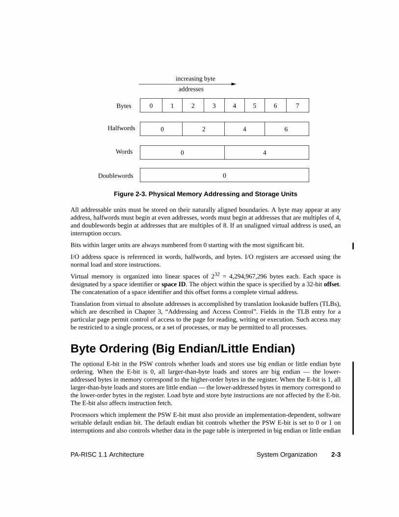
Memory is always referenced with byte addresses, starting with address 0 and extending through thelargest defined non-I/O address (0xEFFFFFFF). Addressable units are bytes, halfwords (2 bytes), words(4 bytes), and doublewords (8 bytes). A comparison of the addressable units is shown in Figure 2-3 withthe relative byte numbers indicated inside the blocks.
Absolute Byte Address
32
Figure 2-1. Absolute Pointer
Figure 2-2. Memory and I/O Addresses
I/OAddressSpace
MemoryAddressSpace 0xF0000000
0xFFFFFFFF
0x00000000
0xFFFFFFFF
2-3PA-RISC 1.1 Architecture System Organization
All addressable units must be stored on their naturally aligned boundaries. A byte may appear at anyaddress, halfwords must begin at even addresses, words must begin at addresses that are multiples of 4,and doublewords begin at addresses that are multiples of 8. If an unaligned virtual address is used, aninterruption occurs.
Bits within larger units are always numbered from 0 starting with the most significant bit.
I/O address space is referenced in words, halfwords, and bytes. I/O registers are accessed using thenormal load and store instructions.
Virtual memory is organized into linear spaces of 232 = 4,294,967,296 bytes each. Each space isdesignated by a space identifier orspace ID. The object within the space is specified by a 32-bitoffset.The concatenation of a space identifier and this offset forms a complete virtual address.
Translation from virtual to absolute addresses is accomplished by translation lookaside buffers (TLBs),which are described in Chapter 3, “Addressing and Access Control”. Fields in the TLB entry for aparticular page permit control of access to the page for reading, writing or execution. Such access maybe restricted to a single process, or a set of processes, or may be permitted to all processes.
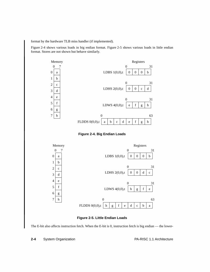
Byte Ordering (Big Endian/Little Endian)The optional E-bit in the PSW controls whether loads and stores use big endian or little endian byteordering. When the E-bit is 0, all larger-than-byte loads and stores are big endian — the lower-addressed bytes in memory correspond to the higher-order bytes in the register. When the E-bit is 1, alllarger-than-byte loads and stores are little endian — the lower-addressed bytes in memory correspond tothe lower-order bytes in the register. Load byte and store byte instructions are not affected by the E-bit.The E-bit also affects instruction fetch.
Processors which implement the PSW E-bit must also provide an implementation-dependent, softwarewritable default endian bit. The default endian bit controls whether the PSW E-bit is set to 0 or 1 oninterruptions and also controls whether data in the page table is interpreted in big endian or little endian
Figure 2-3. Physical Memory Addressing and Storage Units
0
0 4
0 2 4 6
0 1 2 3 4 5 6 7Bytes
Halfwords
Words
Doublewords
increasing byte
addresses
2-4 System Organization PA-RISC 1.1 Architecture
format by the hardware TLB miss handler (if implemented).
Figure 2-4 shows various loads in big endian format. Figure 2-5 shows various loads in little endianformat. Stores are not shown but behave similarly.
The E-bit also affects instruction fetch. When the E-bit is 0, instruction fetch is big endian — the lower-
Figure 2-4. Big Endian Loads
Figure 2-5. Little Endian Loads
a
b
c
d
e
f
g
h
0 b0 0
e hf ga db c
0 31
0 d0 c
0 31
e hf g
0 31
0 63
0
1
2
3
4
5
6
7
LDBS 1(0,0),t
LDHS 2(0,0),t
LDWS 4(0,0),t
FLDDS 0(0,0),t
0 7
Memory Registers
a
b
c
d
e
f
g
h
0 b0 0
d ac bh eg f
0 31
0 c0 d
0 31
h eg f
0 31
0 63
0
1
2
3
4
5
6
7
LDBS 1(0,0),t
LDHS 2(0,0),t
LDWS 4(0,0),t
FLDDS 0(0,0),t
0 7
Memory Registers
2-5PA-RISC 1.1 Architecture System Organization
addressed bytes in memory correspond to the higher-order bytes in the instruction. When the E-bit is 1,instruction fetch is little endian — the lower-addressed bytes in memory correspond to the lower-orderbytes in the instruction.
Architecturally, the instruction byte swapping can occur either when a cache line is moved into theinstruction cache or as instructions are fetched from the I-cache into the pipeline.
Because processors are allowed to swap instructions as they are moved into the I-cache, software isrequired to keep track of which pages might have been brought into the I-cache in big endian form andin little endian form, given the cache move-in rules, and before executing the code, flush all lines on anypage that might have been moved in with the wrong form. Note that the move-in rules allow all lines ona page, plus the next sequential page, to be moved in, so guard pages (that will never be executed) mustbe used between code pages which will execute with opposite endian form.
Levels of PA-RISCFour levels of the processor architecture have been defined:0, 1, 1.5, and2. Level 0 systems supportabsolute memory addressing only; virtual memory is not supported, and so space identifiers are notused. Level 1, 1.5, and 2 systems have virtual addressing and differ only in the number of significantbits in their space identifiers. They have 216, 224, and 232 virtual spaces, respectively. To provide forgrowth to larger systems, each higher level processor has a superset of the capabilities of the lower levelprocessors.
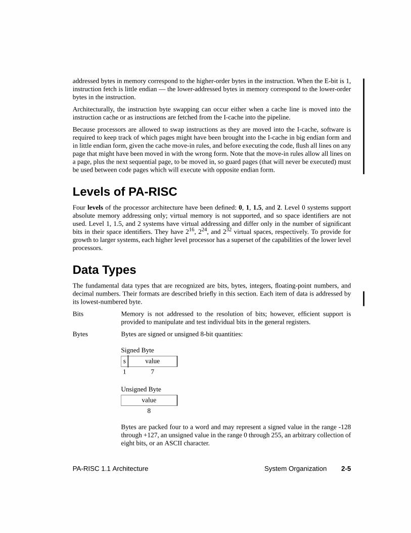
Data TypesThe fundamental data types that are recognized are bits, bytes, integers, floating-point numbers, anddecimal numbers. Their formats are described briefly in this section. Each item of data is addressed byits lowest-numbered byte.
Bits Memory is not addressed to the resolution of bits; however, efficient support isprovided to manipulate and test individual bits in the general registers.
Bytes Bytes are signed or unsigned 8-bit quantities:
Bytes are packed four to a word and may represent a signed value in the range -128through +127, an unsigned value in the range 0 through 255, an arbitrary collection ofeight bits, or an ASCII character.
Signed Byte
s value
1 7
Unsigned Byte
value
8
2-6 System Organization PA-RISC 1.1 Architecture
The character codes conform to the ASCII standard for byte values in the range 0through 127 and to HP’s 8-bit extended Roman-8 character set for byte values in therange 128 through 255.
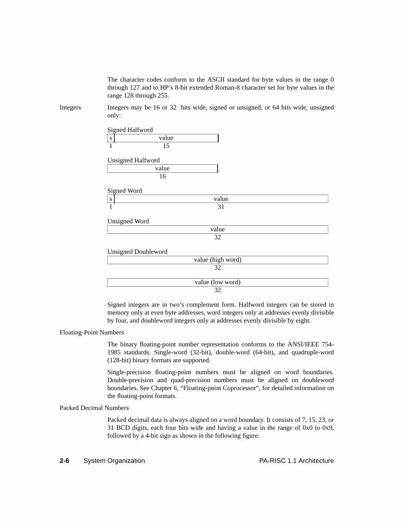
Integers Integers may be 16 or 32 bits wide, signed or unsigned, or 64 bits wide, unsignedonly:
Signed integers are in two’s complement form. Halfword integers can be stored inmemory only at even byte addresses, word integers only at addresses evenly divisibleby four, and doubleword integers only at addresses evenly divisible by eight.
Floating-Point Numbers
The binary floating-point number representation conforms to the ANSI/IEEE 754-1985 standards. Single-word (32-bit), double-word (64-bit), and quadruple-word(128-bit) binary formats are supported.
Single-precision floating-point numbers must be aligned on word boundaries.Double-precision and quad-precision numbers must be aligned on doublewordboundaries. See Chapter 6, “Floating-point Coprocessor”, for detailed information onthe floating-point formats.
Packed Decimal Numbers
Packed decimal data is always aligned on a word boundary. It consists of 7, 15, 23, or31 BCD digits, each four bits wide and having a value in the range of 0x0 to 0x9,followed by a 4-bit sign as shown in the following figure:
Signed Halfwords value1 15
Unsigned Halfwordvalue
16
Signed Words value1 31
Unsigned Wordvalue
32
Unsigned Doublewordvalue (high word)
32
value (low word)32
2-7PA-RISC 1.1 Architecture System Organization
The standard sign for a positive number is 0xC, but any value except 0xD will beinterpreted as positive. 0xD indicates a minus sign for a negative number. 0xB is notsupported as an alternative minus sign.
Processing ResourcesThe architecture provides registers, state information, and protocols for computation, addressing, andcontrol of execution and interruptions. Some of these resources are described below.
Unused Registers and BitsCurrently, there are several registers and bit-fields within registers that do not have any functionassigned to them. All such processing resources are classified into five categories:
1. Reserved bits — Currently unused bits, but reserved for possible future use. A READ operation islegal, and the value read back is all zeros. A WRITE operation is legal but the value written mustbe all zeros. Writing ones is an undefined operation. (For example, writing ones may cause thesebits to no longer read as zeros.)
2. Nonexistent bits — Architecturally these bits do not exist. A READ operation is legal and mayreturn zeros or what was last written. A WRITE operation is also legal, but does not have any effecton system functionality.
3. Undefined bits — Architecturally these bits are undefined. A READ operation is legal and thevalue read is undefined. A WRITE operation is also legal, but does not have any effect on systemfunctionality.
4. Reserved registers — A register that is numbered but currently unused. Both READ and WRITEoperations are undefined operations.
5. Nonexistent registers — A register that does not exist in Level 0 systems. A READ operationreturns zeros. A WRITE operation has no effect (executes as a null instruction).
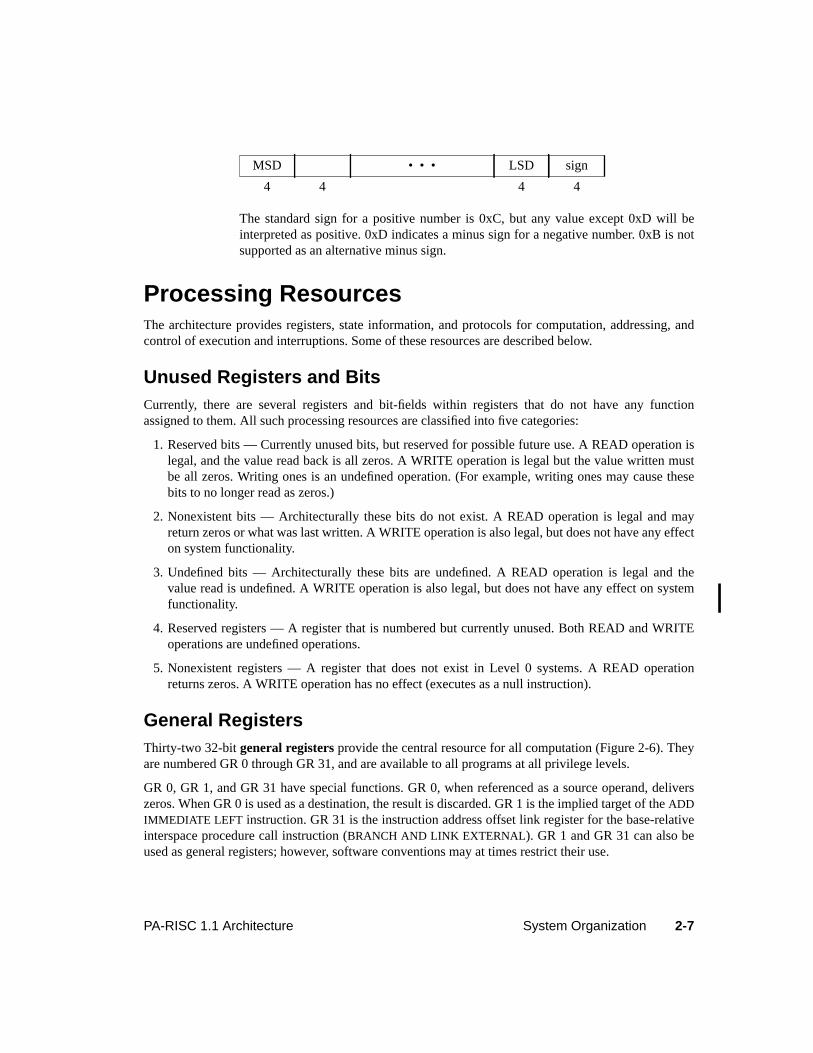
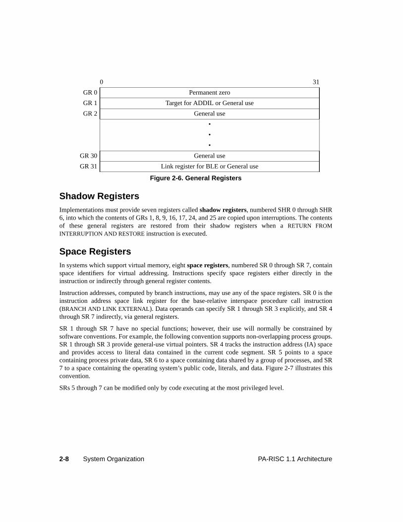
General RegistersThirty-two 32-bitgeneral registers provide the central resource for all computation (Figure 2-6). Theyare numbered GR 0 through GR 31, and are available to all programs at all privilege levels.
GR 0, GR 1, and GR 31 have special functions. GR 0, when referenced as a source operand, deliverszeros. When GR 0 is used as a destination, the result is discarded. GR 1 is the implied target of theADDIMMEDIATE LEFT instruction. GR 31 is the instruction address offset link register for the base-relativeinterspace procedure call instruction (BRANCH AND LINK EXTERNAL). GR 1 and GR 31 can also beused as general registers; however, software conventions may at times restrict their use.
MSD • • • LSD sign
4 4 4 4
2-8 System Organization PA-RISC 1.1 Architecture
Shadow RegistersImplementations must provide seven registers calledshadow registers, numbered SHR 0 through SHR6, into which the contents of GRs 1, 8, 9, 16, 17, 24, and 25 are copied upon interruptions. The contentsof these general registers are restored from their shadow registers when aRETURN FROMINTERRUPTION AND RESTORE instruction is executed.
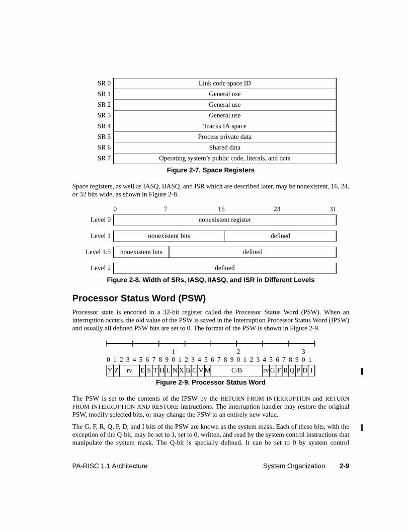
Space RegistersIn systems which support virtual memory, eightspace registers, numbered SR 0 through SR 7, containspace identifiers for virtual addressing. Instructions specify space registers either directly in theinstruction or indirectly through general register contents.
Instruction addresses, computed by branch instructions, may use any of the space registers. SR 0 is theinstruction address space link register for the base-relative interspace procedure call instruction(BRANCH AND LINK EXTERNAL). Data operands can specify SR 1 through SR 3 explicitly, and SR 4through SR 7 indirectly, via general registers.
SR 1 through SR 7 have no special functions; however, their use will normally be constrained bysoftware conventions. For example, the following convention supports non-overlapping process groups.SR 1 through SR 3 provide general-use virtual pointers. SR 4 tracks the instruction address (IA) spaceand provides access to literal data contained in the current code segment. SR 5 points to a spacecontaining process private data, SR 6 to a space containing data shared by a group of processes, and SR7 to a space containing the operating system’s public code, literals, and data. Figure 2-7 illustrates thisconvention.
SRs 5 through 7 can be modified only by code executing at the most privileged level.
0 31
GR 0 Permanent zero
GR 1 Target for ADDIL or General use
GR 2 General use
•
•
•
GR 30 General use
GR 31 Link register for BLE or General use
Figure 2-6. General Registers
2-9PA-RISC 1.1 Architecture System Organization
Space registers, as well as IASQ, IIASQ, and ISR which are described later, may be nonexistent, 16, 24,or 32 bits wide, as shown in Figure 2-8.
Processor Status Word (PSW)Processor state is encoded in a 32-bit register called the Processor Status Word (PSW). When aninterruption occurs, the old value of the PSW is saved in the Interruption Processor Status Word (IPSW)and usually all defined PSW bits are set to 0. The format of the PSW is shown in Figure 2-9.
The PSW is set to the contents of the IPSW by theRETURN FROM INTERRUPTION and RETURNFROM INTERRUPTION AND RESTORE instructions. The interruption handler may restore the originalPSW, modify selected bits, or may change the PSW to an entirely new value.
The G, F, R, Q, P, D, and I bits of the PSW are known as the system mask. Each of these bits, with theexception of the Q-bit, may be set to 1, set to 0, written, and read by the system control instructions thatmanipulate the system mask. The Q-bit is specially defined. It can be set to 0 by system control
SR 0 Link code space ID
SR 1 General use
SR 2 General use
SR 3 General use
SR 4 Tracks IA space
SR 5 Process private data
SR 6 Shared data
SR 7 Operating system’s public code, literals, and data
Figure 2-7. Space Registers
0 7 15 23 31
Level 0 nonexistent register
Level 1 nonexistent bits defined
Level 1.5 nonexistent bits defined
Level 2 defined
Figure 2-8. Width of SRs, IASQ, IIASQ, and ISR in Different Levels
0 1 2 3 4 5 6 7 8 910 1 2 3 4 5 6 7 8 9
20 1 2 3 4 5 6 7 8 9
30 1
Y Z rv E S T H L N X B C V M C/B rv G F R Q P D I
Figure 2-9. Processor Status Word
2-10 System Organization PA-RISC 1.1 Architecture
instructions that manipulate the system mask, but setting it to 1 when the current value is 0 is anundefined operation. The only instructions that can set the Q-bit to 1 are theRETURN FROMINTERRUPTION andRETURN FROM INTERRUPTION AND RESTORE instructions.
Some of the PSW bits are termedmask/unmask bits whereas others are termeddisable/enable bits.Interruptions that are masked remain pending whereas those that are disabled are ignored.
The PSW fields are described below:
Field Description
rv Reserved bits.
Y Data debug trap disable. The Y-bit is set to 0 after the execution of each instruction,except for theRETURN FROM INTERRUPTION andRETURN FROM INTERRUPTIONAND RESTORE instructions which may set it to 1. When 1, data debug traps aredisabled. This bit allows a simple mechanism to trap on a data access and thenproceed past the trapping instruction. Implementation of this bit is required only if thedata debug trap is implemented. If it is not implemented, this bit is a reserved bit.
Z Instruction debug trap disable. The Z-bit is set to 0 after the execution of eachinstruction, except for theRETURN FROM INTERRUPTION and RETURN FROMINTERRUPTION AND RESTORE instructions which may set it to 1. When 1,instruction debug traps are disabled. This bit allows a simple mechanism to trap on aninstruction access and then proceed past the trapping instruction. Implementation ofthis bit is required only if the instruction debug trap is implemented. If it is notimplemented, this bit is a reserved bit.
E Little endian memory access enable. When 0, all memory references are big endian.When 1, all memory references are little endian. Implementation of this bit isoptional. If it is not implemented, all memory references are big endian and this bit isa reserved bit.
S Secure Interval Timer. When 1, the Interval Timer is readable only by code executingat the most privileged level. When 0, the Interval Timer is readable by code executingat any privilege level.
T Taken branch trap enable. When 1, any taken branch is terminated with a takenbranch trap.
H Higher-privilege transfer trap enable. When 1, a higher privilege transfer trap occurswhenever the following instruction is of a higher privilege.
L Lower-privilege transfer trap enable. When 1, a lower privilege transfer trap occurswhenever the following instruction is of a lower privilege.
N Nullify. The current instruction is nullified when this bit is 1. This bit is set to 1 by aninstruction that nullifies the following instruction.
X Data memory break disable. The X-bit is set to 0 after the execution of eachinstruction, except for theRETURN FROM INTERRUPTION and RETURN FROMINTERRUPTION AND RESTORE instructions which may set it to 1. When 1, datamemory break traps are disabled. This bit allows a simple mechanism to trap on all
2-11PA-RISC 1.1 Architecture System Organization
data stores and proceed past them.
B Taken branch. The B-bit is set to 1 by any taken branch instruction and set to 0otherwise. This is used to ensure that the privilege increasing instruction does notcompromise system security.
C Code (instruction) address translation enable. When 1, instruction addresses aretranslated and access rights checked.
V Divide step correction. The integer division primitive instruction records intermediatestatus in this bit to provide a non-restoring divide primitive.
M High-priority machine check mask. When 1, High Priority Machine Checks (HPMCs)are masked. Normally 0, this bit is set to 1 after an HPMC and set to 0 after all otherinterruptions.
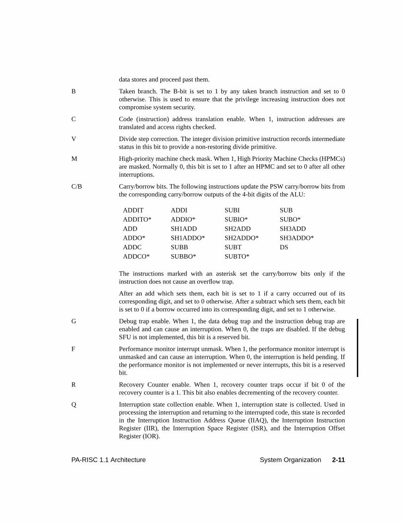
C/B Carry/borrow bits. The following instructions update the PSW carry/borrow bits fromthe corresponding carry/borrow outputs of the 4-bit digits of the ALU:
The instructions marked with an asterisk set the carry/borrow bits only if theinstruction does not cause an overflow trap.
After an add which sets them, each bit is set to 1 if a carry occurred out of itscorresponding digit, and set to 0 otherwise. After a subtract which sets them, each bitis set to 0 if a borrow occurred into its corresponding digit, and set to 1 otherwise.
G Debug trap enable. When 1, the data debug trap and the instruction debug trap areenabled and can cause an interruption. When 0, the traps are disabled. If the debugSFU is not implemented, this bit is a reserved bit.
F Performance monitor interrupt unmask. When 1, the performance monitor interrupt isunmasked and can cause an interruption. When 0, the interruption is held pending. Ifthe performance monitor is not implemented or never interrupts, this bit is a reservedbit.
R Recovery Counter enable. When 1, recovery counter traps occur if bit 0 of therecovery counter is a 1. This bit also enables decrementing of the recovery counter.
Q Interruption state collection enable. When 1, interruption state is collected. Used inprocessing the interruption and returning to the interrupted code, this state is recordedin the Interruption Instruction Address Queue (IIAQ), the Interruption InstructionRegister (IIR), the Interruption Space Register (ISR), and the Interruption OffsetRegister (IOR).
ADDIT ADDI SUBI SUB
ADDITO* ADDIO* SUBIO* SUBO*
ADD SH1ADD SH2ADD SH3ADD
ADDO* SH1ADDO* SH2ADDO* SH3ADDO*
ADDC SUBB SUBT DS
ADDCO* SUBBO* SUBTO*
2-12 System Organization PA-RISC 1.1 Architecture
P Protection identifier validation enable. When this bit and the C-bit are both equal to 1,instruction references check for valid protection identifiers (PIDs). When this bit andthe D-bit are both equal to 1, data references check for valid PIDs. When this bit is 1,probe instructions check for valid PIDs.
D Data address translation enable. When 1, data addresses are translated and accessrights checked.
I External interrupt, power failure interrupt, and low-priority machine checkinterruption unmask. When 1, these interruptions are unmasked and can cause aninterruption. When 0, the interruptions are held pending.
In Level 0 systems, the X, C, P, and D bits are nonexistent bits. In non-Level 0 systems, the Y, Z, and Gbits are reserved bits.
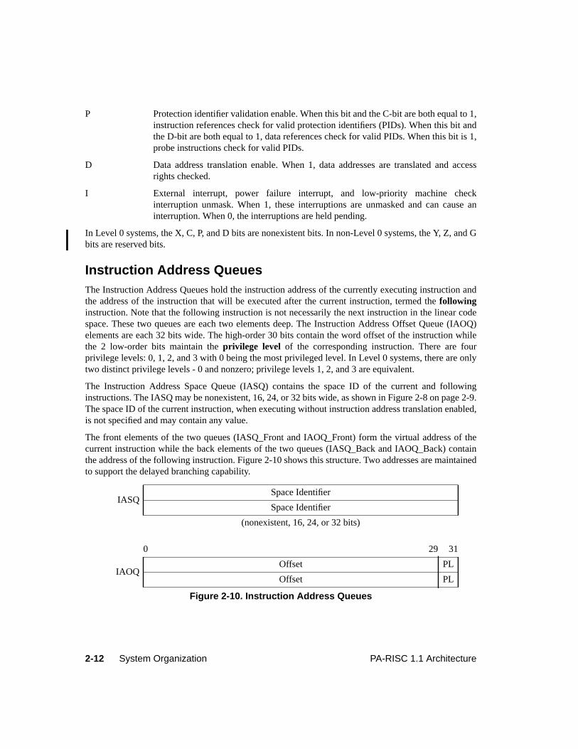
Instruction Address QueuesThe Instruction Address Queues hold the instruction address of the currently executing instruction andthe address of the instruction that will be executed after the current instruction, termed thefollowinginstruction. Note that the following instruction is not necessarily the next instruction in the linear codespace. These two queues are each two elements deep. The Instruction Address Offset Queue (IAOQ)elements are each 32 bits wide. The high-order 30 bits contain the word offset of the instruction whilethe 2 low-order bits maintain theprivilege level of the corresponding instruction. There are fourprivilege levels: 0, 1, 2, and 3 with 0 being the most privileged level. In Level 0 systems, there are onlytwo distinct privilege levels - 0 and nonzero; privilege levels 1, 2, and 3 are equivalent.
The Instruction Address Space Queue (IASQ) contains the space ID of the current and followinginstructions. The IASQ may be nonexistent, 16, 24, or 32 bits wide, as shown in Figure 2-8 on page 2-9.The space ID of the current instruction, when executing without instruction address translation enabled,is not specified and may contain any value.
The front elements of the two queues (IASQ_Front and IAOQ_Front) form the virtual address of thecurrent instruction while the back elements of the two queues (IASQ_Back and IAOQ_Back) containthe address of the following instruction. Figure 2-10 shows this structure. Two addresses are maintainedto support the delayed branching capability.
IASQSpace Identifier
Space Identifier
(nonexistent, 16, 24, or 32 bits)
0 29 31
IAOQOffset PL
Offset PL
Figure 2-10. Instruction Address Queues
2-13PA-RISC 1.1 Architecture System Organization
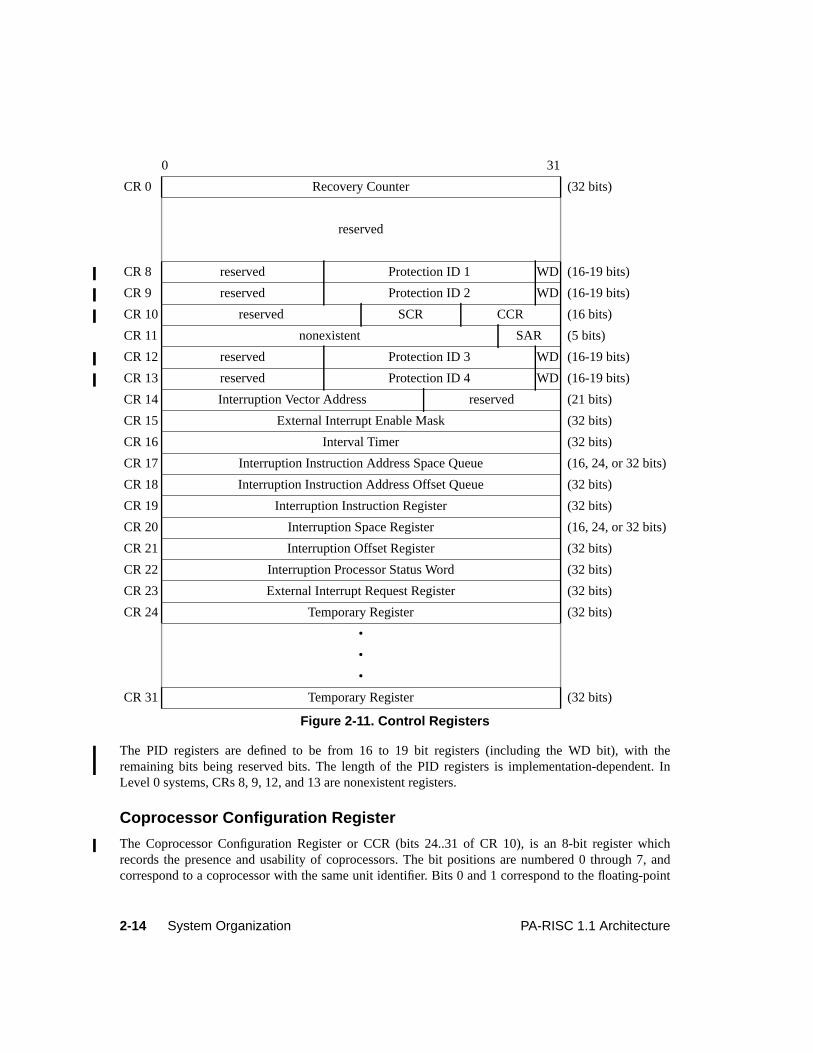
Control RegistersThere are twenty-five definedcontrol registers, numbered CR 0, and CR 8 through CR 31, whichcontain system state information.
CR 11, the Shift Amount Register, is readable and writable by code executing at any privilege level. CR16, the Interval Timer, is readable and writable only by privileged software, unless the PSW S-bit is 0,in which case it is readable by code executing at any privilege level. CR 26 and CR 27, two of thetemporary registers, are readable by code executing at any privilege level and writable only by codeexecuting at the most privileged level. All other defined control registers are accessible only by codeexecuting at the most privileged level.
The control registers are shown in Figure 2-11 and described in the following sections. Moving fromcontrol registers into general registers copies the register right aligned into the general register. Movingto control registers from general registers copies the entire general register into the control register.
Control registers 1 through 7 are reserved registers, and the unused bit positions of the PIDs and theCoprocessor Configuration Register are reserved bits. The unused bits of the Shift Amount Register arenonexistent bits.
In Level 0 systems, CRs 8, 9, 12, 13, 17, and 20 are nonexistent registers.
Recovery Counter
The Recovery Counter (CR 0) is a 32-bit counter that can be used to provide software recovery ofhardware faults in fault-tolerant systems, and can also be used for debugging purposes. CR 0 countsdown by 1 during the execution of each non-nullified instruction for which the PSW R-bit is 1. Therecovery counter is restored if the instruction terminates with a group 1, 2, or 3 interruption (see Chapter4, “Flow Control and Interruptions”). When the leftmost bit of the Recovery Counter is 1, a recoverycounter trap occurs. The trap and the decrement operation can be disabled by setting the PSW R-bit to 0.The value of the Recovery Counter may be read reliably only when the PSW R-bit is 0. The RecoveryCounter may be written reliably only when the PSW R-bit is 0. Otherwise, writing the RecoveryCounter is an undefined operation. If the PSW R-bit is set to 0 by either theRESET SYSTEM MASK ortheMOVE TO SYSTEM MASK instruction, the recovery counter may not be read or written reliably priorto the execution of the eighth instruction after theRESET SYSTEM MASK or theMOVE TO SYSTEMMASK instruction. An interruption, or aRETURN FROM INTERRUPTION or RETURN FROMINTERRUPTION AND RESTORE instruction which sets the PSW R-bit to 0, does not have thisrestriction.
Protection Identifiers
The protection identifiers (CRs 8, 9, 12, 13) designate up to four groups of pages which are accessible tothe currently executing process. When translation is enabled, the four protection identifiers (PIDs) arecompared with a page access identifier in the TLB entry to validate an access. The rightmost bit of eachof the four PIDs is the write disable (WD) bit. When the WD-bit is 1, that PID cannot be used to grantwrite access. This allows each process sharing memory to have different access rights to the memorywithout the overhead of changing the access identifier and access rights in the TLB. When the PSW P-bit is 0, the PIDs, including the WD-bits, are ignored.
2-14 System Organization PA-RISC 1.1 Architecture
The PID registers are defined to be from 16 to 19 bit registers (including the WD bit), with theremaining bits being reserved bits. The length of the PID registers is implementation-dependent. InLevel 0 systems, CRs 8, 9, 12, and 13 are nonexistent registers.
Coprocessor Configuration Register
The Coprocessor Configuration Register or CCR (bits 24..31 of CR 10), is an 8-bit register whichrecords the presence and usability of coprocessors. The bit positions are numbered 0 through 7, andcorrespond to a coprocessor with the same unit identifier. Bits 0 and 1 correspond to the floating-point
0 31
CR 0 Recovery Counter (32 bits)
reserved
CR 8 reserved Protection ID 1 WD (16-19 bits)
CR 9 reserved Protection ID 2 WD (16-19 bits)
CR 10 reserved SCR CCR (16 bits)
CR 11 nonexistent SAR (5 bits)
CR 12 reserved Protection ID 3 WD (16-19 bits)
CR 13 reserved Protection ID 4 WD (16-19 bits)
CR 14 Interruption Vector Address reserved (21 bits)
CR 15 External Interrupt Enable Mask (32 bits)
CR 16 Interval Timer (32 bits)
CR 17 Interruption Instruction Address Space Queue (16, 24, or 32 bits)
CR 18 Interruption Instruction Address Offset Queue (32 bits)
CR 19 Interruption Instruction Register (32 bits)
CR 20 Interruption Space Register (16, 24, or 32 bits)
CR 21 Interruption Offset Register (32 bits)
CR 22 Interruption Processor Status Word (32 bits)
CR 23 External Interrupt Request Register (32 bits)
CR 24 Temporary Register (32 bits)
•
•
•
CR 31 Temporary Register (32 bits)
Figure 2-11. Control Registers
2-15PA-RISC 1.1 Architecture System Organization
coprocessor, and bit 2 corresponds to the performance monitor coprocessor. Bit 7 is the rightmost bit ofthe CCR. It receives bit 31 from a general register when a general register is written to CR 10. Theupper 16 bits of CR 10, and bits within the CCR corresponding to coprocessors which are not present,are reserved bits.
The behavior of the floating-point coprocessor with respect to the state of CCR bits 0 and 1 and thebehavior of the performance monitor coprocessor with respect to the state of CCR bit 2, are specified in“Coprocessor Instructions” on page 5-178. For other coprocessors, setting a bit in the CCR to 1 enablesthe use of the corresponding coprocessor, if present and operational. If a CCR bit is 0, the correspondingcoprocessor, if present, is logically decoupled. This decoupling must ensure that the state of acoprocessor does not change as long as its corresponding CCR bit is 0. When a CCR bit is set to 0 andan attempt is made to execute an instruction which references the corresponding coprocessor, it causesan assist emulation trap. The operation of a coprocessor when its corresponding CCR bit is 0 isexplained in more detail in “Coprocessor Instructions” on page 5-178. It is an undefined operation to setto 1 any CCR bit corresponding to a coprocessor which is not present.
SFU Configuration Register
The SFU Configuration Register or SCR (bits 16..23 of CR 10), is an 8-bit register which records thepresence and usability of special function units. The bit positions are numbered 0 through 7, andcorrespond to an SFU with the same unit identifier. Bit 1 corresponds to the debug SFU. Bit 7 is therightmost bit of the SCR. It receives bit 23 from a general register when a general register is written toCR 10. The upper 16 bits of CR 10, and bits within the SCR corresponding to SFUs which are notpresent, are reserved bits.
For all SFUs, setting a bit in the SCR to 1 enables the use of the corresponding SFU, if present andoperational. If an SCR bit is 0, the corresponding SFU, if present, is logically decoupled. Thisdecoupling must ensure that the state of an SFU does not change as long as its corresponding SCR bit is0. When an SCR bit is set to 0 and an attempt is made to execute an instruction which references thecorresponding SFU, it causes an assist emulation trap. The operation of an SFU when its correspondingSCR bit is 0 is explained in more detail in “Special Function Unit (SFU) Instructions” on page 5-177. Itis an undefined operation to set to 1 any SCR bit corresponding to an SFU which is not present.
Shift Amount Register
The Shift Amount Register or SAR (CR 11), is a 5-bit register used by the variable shift, extract,deposit, and branch on bit instructions. It specifies the number of bits a quantity is to be shifted. Theremaining 27 bits are nonexistent bits and any value can be safely written in those positions.
Interruption Vector Address
The Interruption Vector Address or IVA (CR 14) contains the absolute address of the base of an array ofservice procedures assigned to the interruption classes. This address must be a multiple of 2048. This isbecause the lower 11 bits are reserved bits. Use of an unaligned address is an undefined operation. Thearray of interruption service procedures is indexed by the interruption numbers given in Chapter 4,“Flow Control and Interruptions”.
2-16 System Organization PA-RISC 1.1 Architecture
External Interrupt Enable Mask
The External Interrupt Enable Mask or EIEM (CR 15), is a 32-bit register containing a bit for each ofthe 32 external interrupts. When 0, bits in the EIEM mask interruptions pending for the externalinterrupts corresponding to those bit positions.
Interval Timer
The Interval Timer (CR 16) consists of two internal registers. One of the internal registers is continuallycounting up by 1 at a rate which is implementation-dependent and between twice the "peak instructionrate" and half the "peak instruction rate". Reading the Interval Timer returns the value of this internalregister. The other internal register contains a comparison value and is set by writing to the IntervalTimer. When the counter register and the comparison register contain identical values, bit 0 of theExternal Interrupt Request Register is set to 1. This causes an external interrupt, if enabled.
The Interval Timer can only be written by code executing at the most privileged level. If the PSW S-bitis 1, the Interval Timer can only be read by code executing at the most privileged level; otherwise, it canbe read by code running at any privilege level.
In a multiprocessor system, each processor must have its own interval timer. Each interval timer neednot be synchronized with the other interval timers in the system, nor do they need to be clocked at thesame frequency.
If, as part of a power-saving mode, the processor clock is reduced below the "peak instruction rate", theInterval Timer continues to count at its peak rate. If the processor clock is stopped, the Interval Timermay also stop.
Interruption Instruction Address Queues
The Interruption Instruction Address Space Queue or IIASQ (CR 17) and the Interruption InstructionAddress Offset Queue or IIAOQ (CR 18) are collectively termed the interruption instruction address orIIA queues. They are used to save the Instruction Address and privilege level information for use inprocessing interruptions. The registers are arranged as two two-element deep queues. The queuesgenerally contain the addresses (including the privilege level field in the rightmost two bits of the offsetpart) of the two instructions in the IA queues at the time of the interruption. The IIASQ may benonexistent, 16, 24, or 32 bits wide, as shown in Figure 2-8 on page 2-9.
The IIA queues are continually updated whenever the PSW Q-bit is 1 and are frozen by an interruption(PSW Q-bit becomes 0). After such an interruption, the IIA queues contain copies of the IA queues.Reading the IIAOQ (CR 18) while the PSW Q-bit is 0 retrieves the offset and privilege level portions ofthe front element in the IIAOQ. Writing into IIAOQ while the PSW Q-bit is 0 advances the IIAOQ andthen sets the offset and privilege level portions of the back element of the IIAOQ. Reading the IIASQ(CR 17) while the PSW Q-bit is 0 retrieves the space portion of the front element of the IIASQ. Writinginto IIASQ while the PSW Q-bit is 0 advances the IIASQ and then writes into the back element of theIIASQ. The effect of reading or writing either queue register while the PSW Q-bit is 1 is an undefinedoperation. The Interruption Instruction Address Queues are shown in Figure 2-12.
The state contained in the IIA queues is undefined when aRETURN FROM INTERRUPTION or RETURNFROM INTERRUPTION AND RESTORE instruction sets the PSW Q-bit to 0, or when system control
2-17PA-RISC 1.1 Architecture System Organization
instructions are used to set the PSW Q-bit to 0. If an interruption is taken with the PSW Q-bit equal to 0,the IIA queues are unchanged.
Interruption Parameter Registers
The Interruption Instruction Register or IIR (CR 19), Interruption Space Register or ISR (CR 20), andInterruption Offset Register or IOR (CR 21) are collectively termed the interruption parameter registersor IPRs. They are used to pass an instruction and a virtual address to an interruption handler. The valuesin these registers for each interruption class are specified in Chapter 4, “Flow Control andInterruptions”. These values are set (or frozen) at the time of the interruption whenever the PSW Q-bitis 1. The ISR may be nonexistent, 16, 24, or 32 bits wide, as shown in Figure 2-8 on page 2-9.
The value loaded into the IOR is the full 32-bit offset of the virtual address without truncating therightmost bits or setting them to 0. Writing into the interruption parameter registers is an undefinedoperation.
The values contained in the interruption parameter registers can be read reliably only when the PSW Q-bit is 0. The state contained in the IPRs is undefined when aRETURN FROM INTERRUPTION orRETURN FROM INTERRUPTION AND RESTORE instruction sets the PSW Q-bit to 0, or when systemcontrol instructions are used to set the PSW Q-bit to 0. If an interruption is taken with the PSW Q-bitequal to 0, the IPRs are unchanged.
Interruption Processor Status Word
The Interruption Processor Status Word or IPSW (CR 22) receives the value of the PSW when aninterruption occurs. The layout of IPSW is identical to that of the PSW. The IPSW always reflects thestate of the machine at the point of interruption, regardless of whether the PSW Q-bit was 1 or not. As inthe PSW, the unnamed bits are reserved bits. In Level 0 systems, the X, C, P, and D bits of IPSW arenonexistent bits.
The value contained in the IPSW can be read or written reliably only when the PSW Q-bit is 0. Thestate contained in the IPSW is undefined when aRETURN FROM INTERRUPTION or RETURN FROMINTERRUPTION AND RESTORE instruction sets the PSW Q-bit to 0, or when system controlinstructions are used to set the PSW Q-bit to 0.
IIASQSpace Identifier
Space Identifier
(nonexistent, 16, 24, or 32 bits)
0 29 31
IIAOQOffset PL
Offset PL
Figure 2-12. Interruption Instruction Address Queues
2-18 System Organization PA-RISC 1.1 Architecture
External Interrupt Request Register
The External Interrupt Request register or EIRR (CR 23) is a 32-bit register containing a bit for eachexternal interrupt. When 1, a bit designates that an interruption is pending for the correspondingexternal interrupt. Both the PSW I-bit (external interrupt, power failure interrupt, and low-prioritymachine check unmask) and the corresponding bit position in the External Interrupt Enable Mask (CR15) must be 1 for an interruption to occur.
A MOVE TO CONTROL REGISTER instruction with CR 23 as its target bitwise ANDs the complementof the contents of the source register with the previous contents of CR 23, and places this result in CR23. Thus the processor can only set the EIR register bits to 0.
The IO_EIR register, which is part of the I/O subsystem, is the external name for the EIR register. Whena module writes to it, the bit specified by the value written is set to 1.
Temporary Registers
Six of the eight 32-bit temporary registers (CRs 24, 25, 28 .. 31) are accessible only by code executingat the most privileged level. They provide space to save the contents of the general registers forinterruption handlers in the operating system kernel.
The other two temporary registers (CRs 26 and 27) are readable by code executing at any privilege leveland writable only by code executing at the most privileged level.
Coprocessor RegistersEach coprocessor may have its own register set. The coprocessor mechanism is described in “AssistInstructions” on page 5-176. The floating-point coprocessor registers are described in Chapter 6,“Floating-point Coprocessor”. The performance monitor coprocessor registers are described in Chapter7, “Performance Monitor Coprocessor”.
SFU RegistersEach special function unit may have its own register set. The SFU mechanism is described in “AssistInstructions” on page 5-176. The debug SFU registers are described in Chapter 8, “Debug SpecialFunction Unit”.
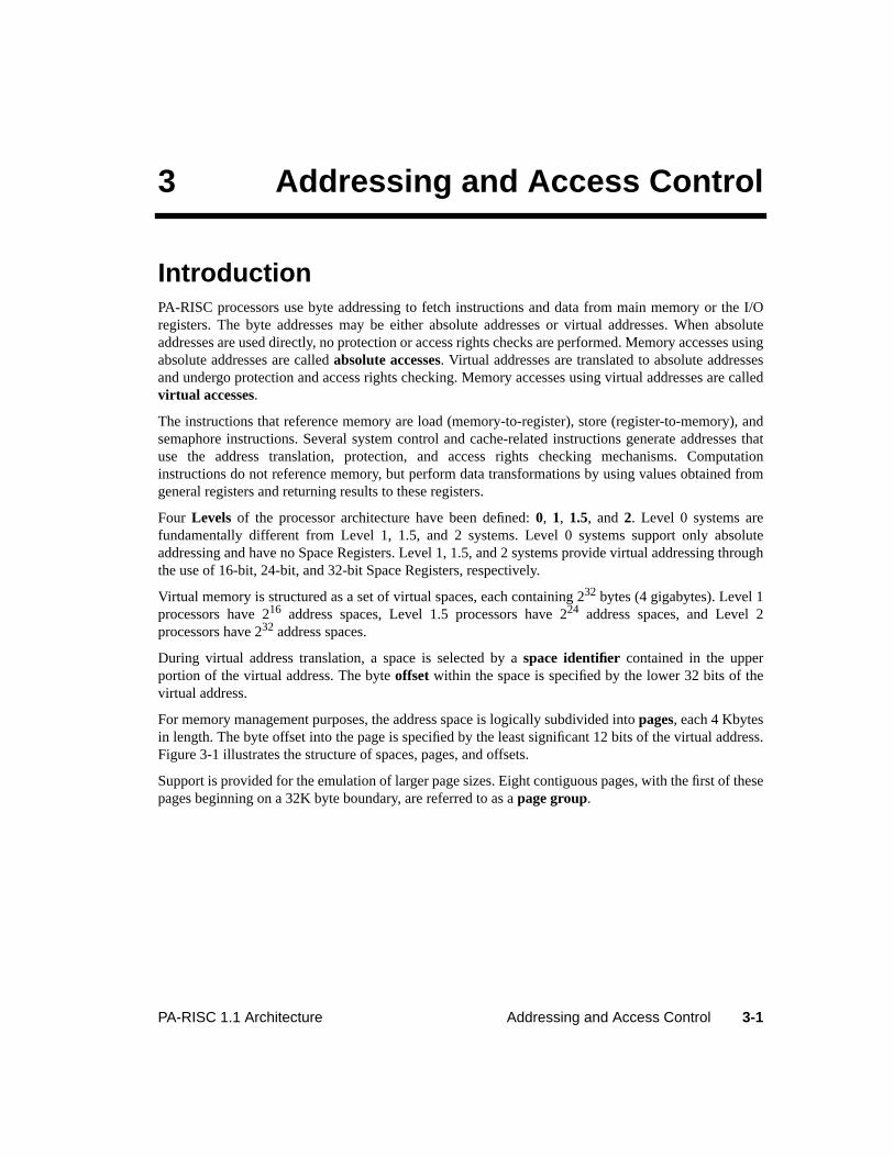
3-1PA-RISC 1.1 Architecture Addressing and Access Control
3 Addressing and Access Control
IntroductionPA-RISC processors use byte addressing to fetch instructions and data from main memory or the I/Oregisters. The byte addresses may be either absolute addresses or virtual addresses. When absoluteaddresses are used directly, no protection or access rights checks are performed. Memory accesses usingabsolute addresses are calledabsolute accesses. Virtual addresses are translated to absolute addressesand undergo protection and access rights checking. Memory accesses using virtual addresses are calledvirtual accesses.
The instructions that reference memory are load (memory-to-register), store (register-to-memory), andsemaphore instructions. Several system control and cache-related instructions generate addresses thatuse the address translation, protection, and access rights checking mechanisms. Computationinstructions do not reference memory, but perform data transformations by using values obtained fromgeneral registers and returning results to these registers.
Four Levels of the processor architecture have been defined:0, 1, 1.5, and2. Level 0 systems arefundamentally different from Level 1, 1.5, and 2 systems. Level 0 systems support only absoluteaddressing and have no Space Registers. Level 1, 1.5, and 2 systems provide virtual addressing throughthe use of 16-bit, 24-bit, and 32-bit Space Registers, respectively.
Virtual memory is structured as a set of virtual spaces, each containing 232 bytes (4 gigabytes). Level 1processors have 216 address spaces, Level 1.5 processors have 224 address spaces, and Level 2processors have 232 address spaces.
During virtual address translation, a space is selected by aspace identifier contained in the upperportion of the virtual address. The byteoffset within the space is specified by the lower 32 bits of thevirtual address.
For memory management purposes, the address space is logically subdivided intopages, each 4 Kbytesin length. The byte offset into the page is specified by the least significant 12 bits of the virtual address.Figure 3-1 illustrates the structure of spaces, pages, and offsets.
Support is provided for the emulation of larger page sizes. Eight contiguous pages, with the first of thesepages beginning on a 32K byte boundary, are referred to as apage group.
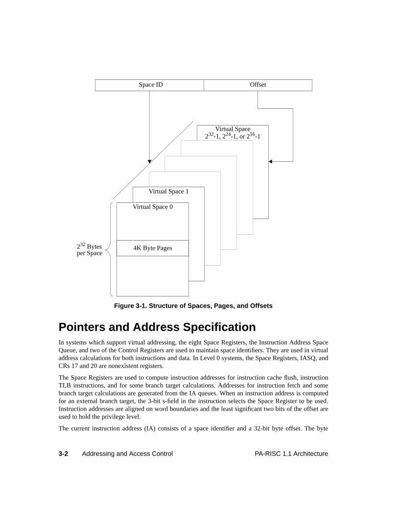
3-2 Addressing and Access Control PA-RISC 1.1 Architecture
Pointers and Address SpecificationIn systems which support virtual addressing, the eight Space Registers, the Instruction Address SpaceQueue, and two of the Control Registers are used to maintain space identifiers. They are used in virtualaddress calculations for both instructions and data. In Level 0 systems, the Space Registers, IASQ, andCRs 17 and 20 are nonexistent registers.
The Space Registers are used to compute instruction addresses for instruction cache flush, instructionTLB instructions, and for some branch target calculations. Addresses for instruction fetch and somebranch target calculations are generated from the IA queues. When an instruction address is computedfor an external branch target, the 3-bit s-field in the instruction selects the Space Register to be used.Instruction addresses are aligned on word boundaries and the least significant two bits of the offset areused to hold the privilege level.
The current instruction address (IA) consists of a space identifier and a 32-bit byte offset. The byte
Figure 3-1. Structure of Spaces, Pages, and Offsets
Space ID Offset
Virtual Space
Virtual Space 1
Virtual Space 0
232-1, 224-1, or 216-1
4K Byte Pages232 Bytesper Space
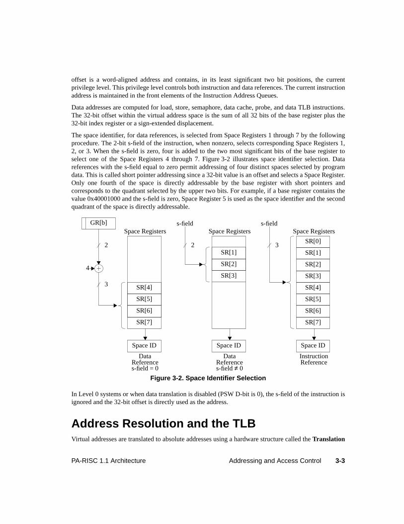
3-3PA-RISC 1.1 Architecture Addressing and Access Control
offset is a word-aligned address and contains, in its least significant two bit positions, the currentprivilege level. This privilege level controls both instruction and data references. The current instructionaddress is maintained in the front elements of the Instruction Address Queues.
Data addresses are computed for load, store, semaphore, data cache, probe, and data TLB instructions.The 32-bit offset within the virtual address space is the sum of all 32 bits of the base register plus the32-bit index register or a sign-extended displacement.
The space identifier, for data references, is selected from Space Registers 1 through 7 by the followingprocedure. The 2-bit s-field of the instruction, when nonzero, selects corresponding Space Registers 1,2, or 3. When the s-field is zero, four is added to the two most significant bits of the base register toselect one of the Space Registers 4 through 7. Figure 3-2 illustrates space identifier selection. Datareferences with the s-field equal to zero permit addressing of four distinct spaces selected by programdata. This is called short pointer addressing since a 32-bit value is an offset and selects a Space Register.Only one fourth of the space is directly addressable by the base register with short pointers andcorresponds to the quadrant selected by the upper two bits. For example, if a base register contains thevalue 0x40001000 and the s-field is zero, Space Register 5 is used as the space identifier and the secondquadrant of the space is directly addressable.
In Level 0 systems or when data translation is disabled (PSW D-bit is 0), the s-field of the instruction isignored and the 32-bit offset is directly used as the address.
Address Resolution and the TLBVirtual addresses are translated to absolute addresses using a hardware structure called theTranslation
Figure 3-2. Space Identifier Selection
SR[1]
SR[2]
SR[3]
Space Registerss-field
Space ID
DataReferences-field≠ 0
SR[0]
SR[1]
SR[2]
SR[3]
SR[4]
SR[5]
SR[6]
SR[7]
Space Registers
SR[4]
SR[5]
SR[6]
SR[7]
Space ID
Space Registers
DataReference
2
s-field = 0
4
GR[b]
Space ID
InstructionReference
s-field
3
2 3
3-4 Addressing and Access Control PA-RISC 1.1 Architecture
Lookaside Buffer (TLB). A TLB accepts a Virtual Page Number and returns the correspondingPhysical Page Number. Since all references in Level 0 systems are absolute accesses, these systems donot have TLBs. A TLB is typically not large enough to hold all the current translations. Translations forall pages in memory are stored in a memory structure called thePage Table. The TLB is organized astwo parts. The instruction TLB (ITLB) is only used for instruction references, while the data TLB(DTLB) is only used for data references. A system may implement acombined TLB which is used forboth instruction and data references.
Additionally, translations are supported for large address ranges. Such translations are calledblocktranslations and are stored in a block TLB. Block translations map address ranges larger than a page.Block translations are useful in mapping virtual address ranges which do not get paged in and out.These block translations increase the virtual address range of the TLB thereby minimizing the virtualaddress translation overhead.
Given a virtual address, the selected TLB is searched for an entry matching the Virtual Page Number. Ifthe entry exists, the 20-bit Physical Page Number (contained in the TLB entry) is concatenated with theoriginal 12-bit page offset to form a 32-bit absolute address. If no such entry exists, the TLB is updatedby either software TLB miss handling or hardware TLB miss handling.
In systems with software TLB miss handling, a TLB miss fault interruption routine performs thetranslation, explicitly inserts the translation and protection fields into the appropriate instruction TLB ordata TLB, and restarts the interrupted instruction. To insure the completion of instructions, the TLBmust be organized to simultaneously hold all necessary translations.
NOTETo fulfill the requirement of holding all the translations simultaneously, it is necessary to haveeither split instruction and data TLBs, or a two or greater way set associative combined TLB.In a system with hardware TLB miss handling, the machine need only insure forward progress.Normally, at most only one instruction and one data address translation are needed. TheFICinstruction is special. Its definition allows using the DTLB for the translation of the target’saddress.
In implementations that provide hardware for TLB miss handling, the hardware attempts to find thevirtual to physical page translation in the Page Table. If the hardware is successful, it inserts thetranslation and protection fields into the appropriate instruction or data TLB. No interruption occurs inthis case. If hardware is not successful, due to a search of the Page Table that was not exhaustive or dueto the appropriate translation not existing in the Page Table, an interruption occurs so that the softwarecan complete the process.
The translation lookaside buffer performs other functions in addition to the basic address translation.The other functions include access control, program debugging support and operating system supportfor virtual memory. Figure 3-3 summarizes the information maintained for each TLB entry.
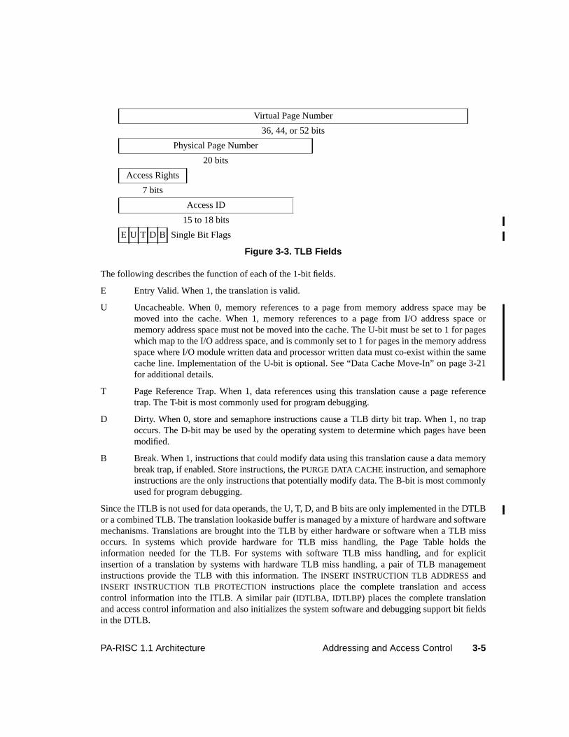
3-5PA-RISC 1.1 Architecture Addressing and Access Control
The following describes the function of each of the 1-bit fields.
E Entry Valid. When 1, the translation is valid.
U Uncacheable. When 0, memory references to a page from memory address space may bemoved into the cache. When 1, memory references to a page from I/O address space ormemory address space must not be moved into the cache. The U-bit must be set to 1 for pageswhich map to the I/O address space, and is commonly set to 1 for pages in the memory addressspace where I/O module written data and processor written data must co-exist within the samecache line. Implementation of the U-bit is optional. See “Data Cache Move-In” on page 3-21for additional details.
T Page Reference Trap. When 1, data references using this translation cause a page referencetrap. The T-bit is most commonly used for program debugging.
D Dirty. When 0, store and semaphore instructions cause a TLB dirty bit trap. When 1, no trapoccurs. The D-bit may be used by the operating system to determine which pages have beenmodified.
B Break. When 1, instructions that could modify data using this translation cause a data memorybreak trap, if enabled. Store instructions, thePURGE DATA CACHE instruction, and semaphoreinstructions are the only instructions that potentially modify data. The B-bit is most commonlyused for program debugging.
Since the ITLB is not used for data operands, the U, T, D, and B bits are only implemented in the DTLBor a combined TLB. The translation lookaside buffer is managed by a mixture of hardware and softwaremechanisms. Translations are brought into the TLB by either hardware or software when a TLB missoccurs. In systems which provide hardware for TLB miss handling, the Page Table holds theinformation needed for the TLB. For systems with software TLB miss handling, and for explicitinsertion of a translation by systems with hardware TLB miss handling, a pair of TLB managementinstructions provide the TLB with this information. TheINSERT INSTRUCTION TLB ADDRESS andINSERT INSTRUCTION TLB PROTECTION instructions place the complete translation and accesscontrol information into the ITLB. A similar pair (IDTLBA , IDTLBP) places the complete translationand access control information and also initializes the system software and debugging support bit fieldsin the DTLB.
Virtual Page Number
36, 44, or 52 bits
Physical Page Number
20 bits
Access Rights
7 bits
Access ID
15 to 18 bits
E U T D B Single Bit Flags
Figure 3-3. TLB Fields
3-6 Addressing and Access Control PA-RISC 1.1 Architecture
Software can be written to operate with a logical page size of 4, 8, 16, or 32 Kbytes. When performingTLB miss handling for a given page, up to all of the eight translations for the page group containing thatpage may be inserted into the TLB, provided that the translation for the given page is inserted last.
On systems with software TLB miss handling, TLB miss traps do not occur on nullified instructions.
Address AliasingNormally, a virtual address does not translate to two different absolute addresses. It is the responsibilityof memory management software to avoid the ambiguity such occurrences would create.
Caches are required to permit a physical memory location to be accessed by both an absolute and avirtual address when the virtual address is equal to the absolute address. Such a virtual address is said tobeequivalently-mapped.
The instruction and data caches are required to detect that the same physical memory location is beingaccessed by two virtual addresses that satisfy all the following requirements:
1. The two virtual addresses map to the same absolute address.
2. Offset bits 12 through 31 are the same in both virtual addresses.
3. If the use of space bits in generating the cache index is enabled, the two virtual addresses differonly in the following space identifier bits: 0, 1, 2, 3, 8, 9, 10, 11, 16, 17, 18, and 19.
Processors must provide an implementation-dependent mechanism to enable/disable the use of spacebits in generating the cache index.
These rules provide offset aliasing on 1 Mbyte boundaries, with optional support for offset aliasing onsmaller power of two sized boundaries, and either restricted or unlimited space aliasing.
Two virtual addresses that satisfy all of the above requirements are calledequivalent aliases of eachother. Virtual addresses that satisfy rule 1 but violate rule 2 or 3 arenon-equivalent aliases, and aremore restricted in their use. For non-equivalent aliases,read-only aliasing is supported with minimalrestrictions, andmany-reader/one-writer aliasing is supported with more significant restrictions.
Generally, if system software must use multiple addresses for the same data, these addresses areequivalent aliases (or are an absolute address and an equivalently-mapped virtual address). Thisdescription of non-equivalent aliasing, and the restrictions on software only apply in rare situationswhen non-equivalent aliasing is necessary.
For the purposes of supporting non-equivalent aliasing, aread-only translation is defined as one wherethe TLB and page table both meet at least one of the following conditions:
• The page type in the access rights field is 0, 2, 4, 5, 6, or 7. (See “Access Control” on page 3-10.)
• The D-bit (dirty bit) is 0.
A translation not meeting this requirement is termed awrite-capable translation.
Software is allowed to have any number of read-only non-equivalently aliased translations to a physicalpage, as long as there are no other translations to the page. This is refered to asread-only non-equivalent aliasing.
3-7PA-RISC 1.1 Architecture Addressing and Access Control
Before a write-capable translation is enabled,all non-equivalently-aliased translations must be removedfrom the page table and purged from the TLB. (Note that the caches are not required to be flushed at thistime.) The write-capable translation may then be used to read and/or modify data on that page. Beforeany non-equivalent aliased translation is re-enabled, the virtual address range for the writable page (theentire page) must be flushed from the cache, and the write-capable translation removed from the pagetable and purged from the TLB. If an old read-only translation is re-enabled, or a translation is enabledthat is equivalently-aliased to an old translation, the virtual address range for the re-enabled translationmust be flushed from the cache before accesses are made to the page. (This flushing is only required ifthe re-enabled virtual page has not been flushed since it was last accessed.) This is refered to asmany-reader/one-writer non-equivalent aliasing.
Absolute read accesses can be made to a page which is mapped with a non-equivalently-mapped read-only transaltion, as long as the absolute address range accessed is flushed before enabling any write-capable translation. Since absolute accesses do not cause prefetching, it is not necessary to flush theentire page - only the accessed range need be flushed.
All other uses of non-equivalent aliasing (including simultaneously enabling multiple non-equivalentlyaliased translations where one or more allow for write access) are prohibited, and can cause machinechecks or silent data corruption, including data corruption of unrelated memory on unrelated pages. It isthe responsibility of privileged software to avoid non-equivalent aliasing, except as described above.This requires flushing the affected address range from the caches prior to any of the following:
• Changing the address mapping in the TLBs.
• Making an absolute access to a location which might reside in the caches as a result of an access bya virtual address that was not equivalently mapped.
• Making a virtual access to a location which might reside in the caches as a result of an access by itsabsolute address that was not equivalently mapped.
• Making a virtual access to a location which may reside in the caches as a result of an access byanother virtual address that was not equivalently aliased.
NOTEThe restrictions on non-equivalent aliases are necessary to allow the design of high-performance caches and memory interconnect, including multi-level caches (including victimor miss caches) and directory-based coherency structures. Coherency schemes are greatlysimplified by allowing the assumption that there is at most a single private copy of a physicalline at any time. The read-only translation informs hardware to request a shared or public copyof the line.
TLB ControlTLBs function as buffers for the most frequently used address translations. Terms used to describeTLBs are given below.
Entry The termentry refers to a translation, either valid or invalid, which is present in theTLB. Entries are visible to software through either references (such as load, store, and
3-8 Addressing and Access Control PA-RISC 1.1 Architecture
semaphore instructions, access rights probes, and theLOAD PHYSICAL ADDRESSinstruction) or insert TLB protection instructions (IITLBP andIDTLBP).
Slot Hardware resources in the TLB which hold entries are referred to asslots.
Invalidate An entry isinvalidated when its E-bit is set to 0 leaving the Virtual Page Number andPhysical Page Number fields unchanged. Invalid entries in the TLB are still visible tosoftware through insert TLB protection instructions.
Remove An entry isremoved when some action causes it to be inaccessible to software.
Insertion of translations into the TLB, for example, causes other entries to beremoved. TLB systems can also remove an entry by logically decoupling from theTLB the slot which contained the entry.
NOTEIn a two-level TLB, moving a translation from the second level to the first level can cause atranslation to disappear from the TLB (because the level 1 TLB need not be a proper subset ofthe level 2 TLB). This is an example of removal.
Alter An entry isaltered when its E-bit is set to 0, and the Physical Page Number field ismodified, but the Virtual Page Number field is left unchanged. Altered entries in theTLB are still visible to software through the insert TLB protection instructions.
Several mechanisms can be used by software to invalidate or remove a specific translation from theITLB or DTLB. First, when a new translation is inserted into the TLB, the old translation for the sameVirtual Page Number (if present) is removed. Second, a specific virtual address may be used to purge(invalidate or remove) the associated translation from the TLB. ThePURGE INSTRUCTION TLB andPURGE DATA TLB instructions perform this function. These instructions also cause the translation to beinvalidated or removed from the TLBs of other processors in a multiprocessor system. There is noinstruction to purge a translation from both the instruction and data TLBs simultaneously.
Translations may also be invalidated or removed from the TLB using thePURGE INSTRUCTION TLBENTRY and thePURGE DATA TLB ENTRY instructions. These purge zero or more machine specificentries in the TLB without regard for the translation. These instructions are used by system software toclear the entire instruction or data TLB.
Because the TLB is managed by a mixture of hardware and software mechanisms, software may not, ingeneral, rely on the existence of translations in the TLB and hardware may, in general, invalidate orremove TLB entries at any time, provided that forward progress is assured. There are limited situations,however, in which software may rely on a translation existing in the TLB. This means that software maymake virtual accesses using thisrelied-upon translation, and no TLB miss fault will occur. Hardwareis required to retain this TLB entry as long as the constraints of the limited situation are met. Thesesituations are described in “TLB Operation Requirements” on page 3-18.
3-9PA-RISC 1.1 Architecture Addressing and Access Control
NOTEAs a result, the following hardware actions are allowed, except in the defined limitedsituations.
• A TLB miss fault may be taken even though the translation exists in the TLB.
• In the event of a TLB error, one or more entries may be invalidated or removed.
Note also that software may not rely on the existence of any translations in the TLBimmediately after any group 1, 2, or 4 interruption.
The following are the only ways in which TLB entries may exist which are visible to software andwhich were not inserted into the TLB by software.
1. When a TLB entry is inserted by a hardware TLB miss handler.
2. When a valid TLB entry is invalidated by a purge TLB instruction, the TLB entry may be altered.
3. When a valid TLB entry is invalidated by a purge TLB instruction executed on another processor ina multiprocessor system, the TLB entry may be altered.
4. The PURGE INSTRUCTION TLB ENTRY andPURGE DATA TLB ENTRY instructions, as well asinitialization and power failure can cause all fields but the E-bit to be set to arbitrary values in someor all of the TLB entries. The E-bit is set to 0 in all entries modified by these instructions.
Software must manage the virtual to absolute address mappings with the knowledge that purge TLBinstructions can alter translations in other processors and that initialization, power failure, and purgeTLB entry instructions leave the TLB with arbitrary invalid translations.
Software TLB Miss HandlingIn order to insure forward progress, some restrictions are placed on software which performs TLB misshandling.
For instruction TLB miss handling, the following restrictions apply:
• Software can insert multiple instruction address translations into the ITLB, usingINSERTINSTRUCTION TLB ADDRESS and INSERT INSTRUCTION TLB PROTECTION instructions,provided that the translation which caused the trap is inserted last.
• Software must not execute a purge TLB instruction using the virtual address corresponding to thedata address translation needed for the execution of the trapping instruction.
• Software must not insert translations into the DTLB.
For non-access instruction TLB miss handling, the following restrictions apply:
• Software can only insert into the ITLB up to all of the eight translations for the page group. Thetranslation which caused the trap must be inserted last.
• Software must not execute a purge TLB instruction using the virtual address corresponding to thedata address translation needed for the execution of the trapping instruction.
3-10 Addressing and Access Control PA-RISC 1.1 Architecture
• Software must not insert translations into the DTLB.
For data TLB miss handling, the following restrictions apply:
• Software can only insert into the DTLB up to all of the eight translations for the page group. Thetranslation which caused the trap must be inserted last.
• Software must not execute a purge TLB instruction using the virtual address corresponding to theinstruction address translation needed for the execution of the trapping instruction.
For non-access data TLB miss handling, the following restrictions apply:
• Software can only insert into the DTLB up to all of the eight translations for the page group. Thetranslation which caused the trap must be inserted last.
• Software must not execute a purge TLB instruction using the virtual address corresponding to theinstruction address translation needed for the execution of the trapping instruction.
The following restrictions apply to all four TLB miss handlers:
• Software must not make any virtual references.
• Software must not execute anyPURGE DATA TLB ENTRY or PURGE INSTRUCTION TLB ENTRYinstructions.
Hardware TLB Miss HandlingThe default endian bit (see “Byte Ordering (Big Endian/Little Endian)” on page 2-3) determines howdata from the hardware-visible page table is interpreted by the hardware TLB miss handler, ifimplemented. If the default endian bit is 0, the hardware-visible page table entries are loaded as wordsin big-endian format; if the default endian bit is 1, the entries are loaded as words in little-endian format.
Access ControlA set of mechanisms is available to system software to provide a secure and protected environment foruser processes. These mechanisms are collectively known as access control and are provided as a part ofthe address translation mechanism. Processor resources, including the PSW, Control Registers, andTLB entries, contain information used to determine the allowed use of a page. Access control isavailable only when address translation is enabled, and is done on a per-page basis. Access control isnot available in Level 0 systems.
An access is validated if the check of the access rights and the protection identifiers both succeed. If theaccess is validated, the instruction reference or data reference is completed. If the access is notvalidated, the instruction is terminated with a protection trap. Instruction access violations are reportedwith instruction memory protection traps. Data read and write access violations are reported with datamemory access rights or data memory protection ID traps. Probe instructions are special; they save theresult of the access validation in a General Register and do not cause a protection trap. An access rightscheck is based on the type of access and the current privilege level. The protection identifier checkcompares the Protection ID Registers with a page-based access identifier in the TLB. State bits withinthe PSW determine when these checks are enabled.
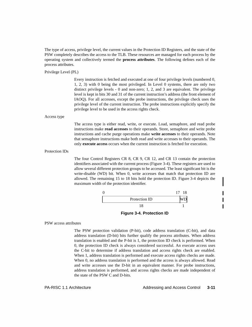
3-11PA-RISC 1.1 Architecture Addressing and Access Control
The type of access, privilege level, the current values in the Protection ID Registers, and the state of thePSW completely describes the access to the TLB. These resources are managed for each process by theoperating system and collectively termed theprocess attributes. The following defines each of theprocess attributes.
Privilege Level (PL)
Every instruction is fetched and executed at one of four privilege levels (numbered 0,1, 2, 3) with 0 being the most privileged. In Level 0 systems, there are only twodistinct privilege levels - 0 and non-zero; 1, 2, and 3 are equivalent. The privilegelevel is kept in bits 30 and 31 of the current instruction’s address (the front element ofIAOQ). For all accesses, except the probe instructions, the privilege check uses theprivilege level of the current instruction. The probe instructions explicitly specify theprivilege level to be used in the access rights check.
Access type
The access type is either read, write, or execute. Load, semaphore, and read probeinstructions makeread accesses to their operands. Store, semaphore and write probeinstructions and cache purge operations makewrite accesses to their operands. Notethat semaphore instructions make both read and write accesses to their operands. Theonly execute access occurs when the current instruction is fetched for execution.
Protection IDs
The four Control Registers CR 8, CR 9, CR 12, and CR 13 contain the protectionidentifiers associated with the current process (Figure 3-4). These registers are used toallow several different protection groups to be accessed. The least significant bit is thewrite-disable (WD) bit. When 0, write accesses that match that protection ID areallowed. The remaining 15 to 18 bits hold the protection ID. Figure 3-4 depicts themaximum width of the protection identifier.
PSW access attributes
The PSW protection validation (P-bit), code address translation (C-bit), and dataaddress translation (D-bit) bits further qualify the process attributes. When addresstranslation is enabled and the P-bit is 1, the protection ID check is performed. When0, the protection ID check is always considered successful. An execute access usesthe C-bit to determine if address translation and access rights check are enabled.When 1, address translation is performed and execute access rights checks are made.When 0, no address translation is performed and the access is always allowed. Readand write accesses use the D-bit in an equivalent manner. For probe instructions,address translation is performed, and access rights checks are made independent ofthe state of the PSW C and D-bits.
0 17 18
Protection ID WD
18 1
Figure 3-4. Protection ID
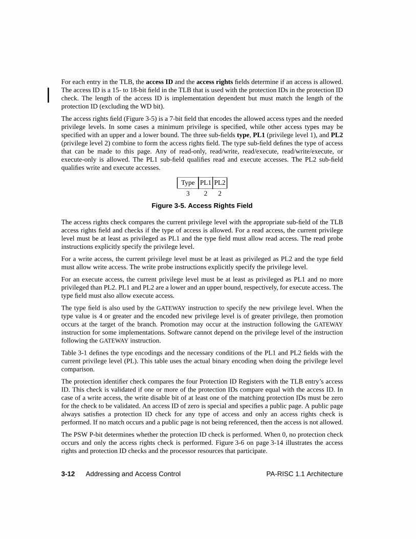
3-12 Addressing and Access Control PA-RISC 1.1 Architecture
For each entry in the TLB, theaccess ID and theaccess rights fields determine if an access is allowed.The access ID is a 15- to 18-bit field in the TLB that is used with the protection IDs in the protection IDcheck. The length of the access ID is implementation dependent but must match the length of theprotection ID (excluding the WD bit).
The access rights field (Figure 3-5) is a 7-bit field that encodes the allowed access types and the neededprivilege levels. In some cases a minimum privilege is specified, while other access types may bespecified with an upper and a lower bound. The three sub-fieldstype, PL1 (privilege level 1), andPL2(privilege level 2) combine to form the access rights field. The type sub-field defines the type of accessthat can be made to this page. Any of read-only, read/write, read/execute, read/write/execute, orexecute-only is allowed. The PL1 sub-field qualifies read and execute accesses. The PL2 sub-fieldqualifies write and execute accesses.
The access rights check compares the current privilege level with the appropriate sub-field of the TLBaccess rights field and checks if the type of access is allowed. For a read access, the current privilegelevel must be at least as privileged as PL1 and the type field must allow read access. The read probeinstructions explicitly specify the privilege level.
For a write access, the current privilege level must be at least as privileged as PL2 and the type fieldmust allow write access. The write probe instructions explicitly specify the privilege level.
For an execute access, the current privilege level must be at least as privileged as PL1 and no moreprivileged than PL2. PL1 and PL2 are a lower and an upper bound, respectively, for execute access. Thetype field must also allow execute access.
The type field is also used by theGATEWAY instruction to specify the new privilege level. When thetype value is 4 or greater and the encoded new privilege level is of greater privilege, then promotionoccurs at the target of the branch. Promotion may occur at the instruction following theGATEWAYinstruction for some implementations. Software cannot depend on the privilege level of the instructionfollowing theGATEWAY instruction.
Table 3-1 defines the type encodings and the necessary conditions of the PL1 and PL2 fields with thecurrent privilege level (PL). This table uses the actual binary encoding when doing the privilege levelcomparison.
The protection identifier check compares the four Protection ID Registers with the TLB entry’s accessID. This check is validated if one or more of the protection IDs compare equal with the access ID. Incase of a write access, the write disable bit of at least one of the matching protection IDs must be zerofor the check to be validated. An access ID of zero is special and specifies a public page. A public pagealways satisfies a protection ID check for any type of access and only an access rights check isperformed. If no match occurs and a public page is not being referenced, then the access is not allowed.
The PSW P-bit determines whether the protection ID check is performed. When 0, no protection checkoccurs and only the access rights check is performed. Figure 3-6 on page 3-14 illustrates the accessrights and protection ID checks and the processor resources that participate.
Type PL1 PL2
3 2 2
Figure 3-5. Access Rights Field
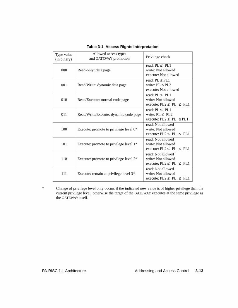
3-13PA-RISC 1.1 Architecture Addressing and Access Control
* Change of privilege level only occurs if the indicated new value is of higher privilege than thecurrent privilege level; otherwise the target of theGATEWAY executes at the same privilege astheGATEWAY itself.
Table 3-1. Access Rights Interpretation
Type value(in binary)
Allowed access typesandGATEWAY promotion Privilege check
000 Read-only: data pageread: PL≤ PL1write: Not allowedexecute: Not allowed
001 Read/Write: dynamic data pageread: PL≤ PL1write: PL≤ PL2execute: Not allowed
010 Read/Execute: normal code pageread: PL≤ PL1write: Not allowedexecute: PL2≤ PL ≤ PL1
011 Read/Write/Execute: dynamic code pageread: PL≤ PL1write: PL≤ PL2execute: PL2≤ PL ≤ PL1
100 Execute: promote to privilege level 0*read: Not allowedwrite: Not allowedexecute: PL2≤ PL ≤ PL1
101 Execute: promote to privilege level 1*read: Not allowedwrite: Not allowedexecute: PL2≤ PL ≤ PL1
110 Execute: promote to privilege level 2*read: Not allowedwrite: Not allowedexecute: PL2≤ PL ≤ PL1
111 Execute: remain at privilege level 3*read: Not allowedwrite: Not allowedexecute: PL2≤ PL ≤ PL1
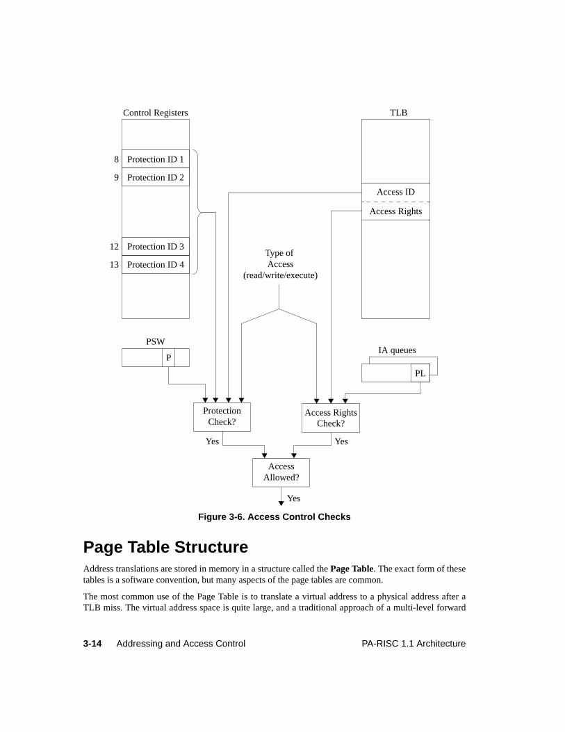
3-14 Addressing and Access Control PA-RISC 1.1 Architecture
Page Table StructureAddress translations are stored in memory in a structure called thePage Table. The exact form of thesetables is a software convention, but many aspects of the page tables are common.
The most common use of the Page Table is to translate a virtual address to a physical address after aTLB miss. The virtual address space is quite large, and a traditional approach of a multi-level forward
Figure 3-6. Access Control Checks
Protection ID 1
Control Registers
AccessAllowed?
Protection ID 2
Protection ID 3
Protection ID 4
8
9
12
13
TLB
Access ID
Access Rights
ProtectionCheck?
Access RightsCheck?
Type ofAccess
(read/write/execute)
PSWIA queues
P
YesYes
Yes
PL
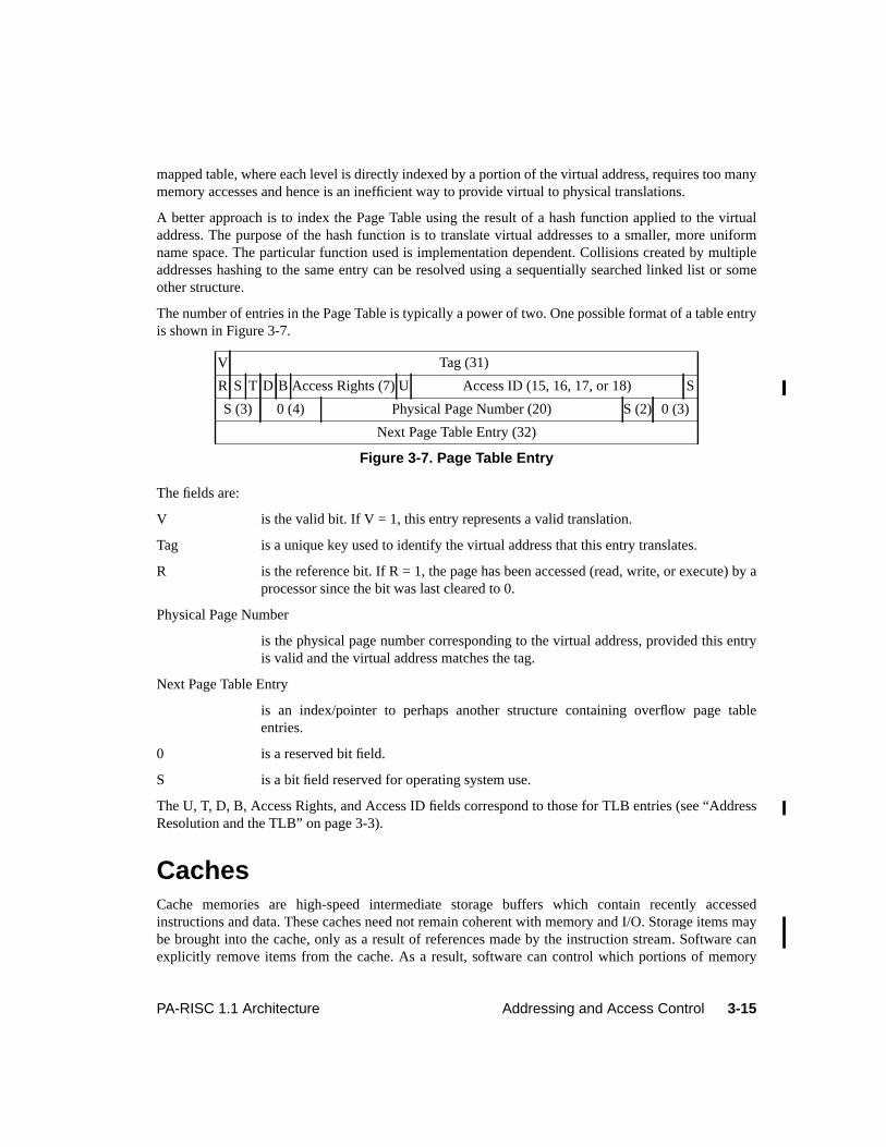
3-15PA-RISC 1.1 Architecture Addressing and Access Control
mapped table, where each level is directly indexed by a portion of the virtual address, requires too manymemory accesses and hence is an inefficient way to provide virtual to physical translations.
A better approach is to index the Page Table using the result of a hash function applied to the virtualaddress. The purpose of the hash function is to translate virtual addresses to a smaller, more uniformname space. The particular function used is implementation dependent. Collisions created by multipleaddresses hashing to the same entry can be resolved using a sequentially searched linked list or someother structure.
The number of entries in the Page Table is typically a power of two. One possible format of a table entryis shown in Figure 3-7.
The fields are:
V is the valid bit. If V = 1, this entry represents a valid translation.
Tag is a unique key used to identify the virtual address that this entry translates.
R is the reference bit. If R = 1, the page has been accessed (read, write, or execute) by aprocessor since the bit was last cleared to 0.
Physical Page Number
is the physical page number corresponding to the virtual address, provided this entryis valid and the virtual address matches the tag.
Next Page Table Entry
is an index/pointer to perhaps another structure containing overflow page tableentries.
0 is a reserved bit field.
S is a bit field reserved for operating system use.
The U, T, D, B, Access Rights, and Access ID fields correspond to those for TLB entries (see “AddressResolution and the TLB” on page 3-3).
CachesCache memories are high-speed intermediate storage buffers which contain recently accessedinstructions and data. These caches need not remain coherent with memory and I/O. Storage items maybe brought into the cache, only as a result of references made by the instruction stream. Software canexplicitly remove items from the cache. As a result, software can control which portions of memory
V Tag (31)
R S T D B Access Rights (7) U Access ID (15, 16, 17, or 18) S
S (3) 0 (4) Physical Page Number (20) S (2) 0 (3)
Next Page Table Entry (32)
Figure 3-7. Page Table Entry
3-16 Addressing and Access Control PA-RISC 1.1 Architecture
may be present in the cache. Items in the cache may be removed by hardware at any time. Software maytherefore not rely on particular items remaining in the cache.
A consistent software view of cache operation requires that implementations never write a clean cacheline back to memory.Clean means "not stored into" as opposed to "not changed".Dirty means "storedinto". A cache line which was stored into in such a way that it was unchanged is considered to be dirty.
To insure memory system coherence, and to minimize cache flushing, instructions and data in memorymay be brought into the caches only under certain circumstances. This operation of bringinginformation from memory into a cache is referred to asmove-in. In general, only instructions and datareferenced by executed instructions may be moved in. Software may use reference bits and othermechanisms controlled by interruptions to determine when lines are potentially in the instruction cache,data cache, or both.
No data reference may cause a move-in to the instruction cache and no instruction reference may causea move-in to the data cache. This means that the execution of aFLUSH DATA CACHE or PURGE DATACACHE instruction guarantees that the addressed line, if it has been referenced as data but not asinstructions, is no longer present in the cache system. Similarly, only aFLUSH INSTRUCTION CACHEinstruction is required to guarantee that a line which has been referenced as instructions but not as data,is no longer present in the cache system. The actions which constitute a reference are described in “DataCache Move-In” on page 3-21 and “Instruction Cache Move-In” on page 3-22.
If implemented, the U (Uncacheable) bit is found in the data TLB entry associated with a page. Whetheror not the U-bit is implemented, the state of this bit if implemented, whether the memory reference isvirtual or absolute, and whether the reference is made from a page in the memory or I/O address spacesdetermine if the reference may be moved into the data cache. The detailed rules for moving referencesinto the data cache are specified in “Data Cache Move-In” on page 3-21.
Software must set the U-bit associated with all pages in the I/O address space to 1. Referencing a pagein the I/O address space for which the U-bit is 0 is an undefined operation.
Changing the state of the U-bit for a page has no effect on the data cache lines from that page whichalready exist in the cache. A page from the memory address space which has its U-bit set to 0 is called acacheable page. Pages from the I/O address space and pages which have their U-bit set to 1 are calleduncacheable pages. It is possible for data cache lines from an uncacheable page to exist in a data cache.This case may be caused by changing a cacheable page to uncacheable after references to this page weremoved into the data cache.
The Synchronization PrimitiveProgram synchronization can be done using theLOAD AND CLEAR WORD instructions, which performindivisible semaphore operations. These instructions are required to use 16-byte aligned addresses.When using semaphores to synchronize with I/O, care must be taken in placing other information in thesame cache line as the semaphore. Data which is writable, can only be placed in the same cache line asa semaphore if access to write the data is controlled by the semaphore.
3-17PA-RISC 1.1 Architecture Addressing and Access Control
Cache Coherence with I/OAccesses to memory by I/O modules may be either coherent or non-coherent with processor datacaches.
Coherent I/OProcessors in systems with coherent I/O modules must implement theLOAD COHERENCE INDEXinstruction, which loads the coherence index corresponding to a given virtual address into a GeneralRegister. Coherent I/O modules provide the coherence index along with the absolute address of data it isreading from or writing to memory. The coherence index must provide enough information such that,together with the absolute address, the processor can find data that was brought into its data cache bythe original virtual address.
Software need not flush or purge data from the data cache when sharing the data with a coherent I/Omodule. For I/O output (e.g., memory to secondary storage), the coherent I/O module performs coherentread operations which will read the data from memory or a processor’s data cache depending on wherethe most up-to-date copy is located. For I/O input, the coherent I/O module performs coherent writeoperations which will write the data to memory and also update or invalidate matching lines inprocessor data caches.
Coherent I/O operations are not coherent with instruction caches. Software is responsible for flushingthe appropriate instruction cache lines before or after the I/O operation.
Non-coherent I/ONon-coherent I/O modules process data in memory; this data can be non-coherent with processorcaches. Software is required to insure that:
1. The contents of the appropriate caches are flushed to main memory prior to an I/O output (e.g.,memory to secondary storage) operation.
2. The contents of the appropriate caches are purged or flushed prior to an I/O input (e.g., secondarystorage to memory) operation.
3. The contents of the appropriate caches are purged following an I/O input operation, if the cachemove-in rules would have allowed the processor to move the data into the cache during the I/Ooperation.
Cache Coherence in Multiprocessor SystemsMultiprocessor systems may include PA-RISC processors as well as other processors.
The cache-coherent part of a multiprocessor system is required to behave as if there were logically asingle D-cache and a single I-cache. If there are multiple physical D-caches, they must cross-interrogatefor current data and must broadcast purge and flush operations except forFDCE andFICE. Purge andflush operations do not cause TLB faults on other processors. Multiple I-caches require only that flushesbe broadcast. The I-cache is read-only, and software is responsible for modifications to the instruction
3-18 Addressing and Access Control PA-RISC 1.1 Architecture
stream.
The non-cache-coherent part of a multiprocessor system (if any) may either cross-interrogate with thecaches in the cache-coherent part of the system, or may have an independent cache system. This designdecision is generally based on the frequency of data sharing.
In the cache-coherent part of a multiprocessor system, all data references to cacheable pages must besatisfied by data that was obtained using cache coherence checks, and has remained coherent since thedata was moved in. Data references to uncacheable pages do not need to be satisfied by data that wasobtained using cache coherence checks. Data from an uncacheable page could be in a cache if it wasmoved in when that page was marked cacheable, but the page is now marked uncacheable.
Implementations with write buffers must also check buffer contents on cache coherence checks, in orderto insure proper ordering of storage accesses.
Instruction references need not be satisfied by data that was obtained using cache coherence checks.
Instruction caches are read-only. In the case of a separate instruction cache implementation, instructioncache lines must never be written back to main memory.
TLB Coherence in Multiprocessor SystemsThe cache-coherent part of a multiprocessor system is required to behave as if there were logically asingle DTLB and a single ITLB.
All TLBs in a multiprocessor system are required to broadcast purges, exceptPDTLBE andPITLBE, toall other TLBs. The originating processor’s purge instruction suspends until all target processorscomplete the purge.
TLB Operation RequirementsSoftware may rely on the existence of particular translations in the TLB only in certain situations. Thefollowing describes the situations in which software may rely upon the fact that a specific translationwill continue to exist in the TLB. In these situations, software may make virtual accesses using therelied-upon translation, and no TLB miss fault will occur (including non-access TLB miss faults).
1. When an instruction takes one of the following interruptions, the associated data address translation
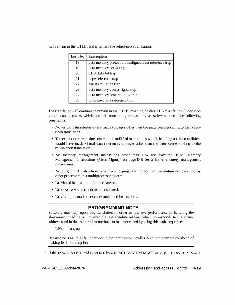
3-19PA-RISC 1.1 Architecture Addressing and Access Control
will remain in the DTLB, and is termed the relied-upon translation.
The translation will continue to remain in the DTLB, meaning no data TLB miss fault will occur onvirtual data accesses which use this translation, for as long as software meets the followingconstraints:
• No virtual data references are made to pages other than the page corresponding to the relied-upon translation.
• The execution stream does not contain nullified instructions which, had they not been nullified,would have made virtual data references to pages other than the page corresponding to therelied-upon translation.
• No memory management instructions other thanLPA are executed. (See “MemoryManagement Instructions (Mem_Mgmt)” on page D-5 for a list of memory managementinstructions.)
• No purge TLB instructions which would purge the relied-upon translation are executed byother processors in a multiprocessor system.
• No virtual instruction references are made.
• No DIAGNOSE instructions are executed.
• No attempt is made to execute undefined instructions.
PROGRAMMING NOTESoftware may rely upon this translation in order to improve performance in handling theabove-mentioned traps. For example, the absolute address which corresponds to the virtualaddress used in the trapping instruction can be determined by using this code sequence:
LPA x(s,b),t
Because no TLB miss fault can occur, the interruption handler need not incur the overhead ofmaking itself interruptible.
2. If the PSW Q-bit is 1, and is set to 0 by a RESET SYSTEM MASK orMOVE TO SYSTEM MASK
Intr. No. Interruption
18 data memory protection/unaligned data reference trap
19 data memory break trap
20 TLB dirty bit trap
21 page reference trap
22 assist emulation trap
26 data memory access rights trap
27 data memory protection ID trap
28 unaligned data reference trap
3-20 Addressing and Access Control PA-RISC 1.1 Architecture
instruction, the instruction address translation used to fetch theRSM or MTSM instruction willcontinue to remain in the ITLB, and is termed the relied-upon translation. No instruction TLB missfault will occur on virtual instruction accesses which use this translation for as long as softwaremeets the following constraints:
• TheRSM or MTSM instruction which sets the PSW Q-bit to 0 (theclearing RSM or MTSM) ispreceded by anotherRSM, SSM, or MTSM instruction which does not affect the PSW Q-bit,and which appears at least 8 instructions prior.
• The instructions between the initialRSM, SSM, or MTSM instruction and the clearingRSM orMTSM do not include any memory management instructions, virtual data references, orinstruction references to pages other than the code page containing the clearingRSM or MTSMinstruction.
• The clearingRSM or MTSM instruction is not within 8 instructions of a page boundary.
• No virtual data references are made.
• The execution stream does not contain nullified instructions which would have made virtualdata references had they not been nullified.
• No FLUSH INSTRUCTION CACHE instructions are executed with the PSW D-bit equal to 1.
• No memory management instructions are executed. (See Appendix D, “Operation Codes” for alist of memory management instructions.)
• No purge TLB instructions which would purge the relied-upon translation are executed byother processors in a multiprocessor system.
• No instruction references are made to pages other than the code page containing the clearingRSM or MTSM instruction.
• No DIAGNOSE instructions are executed.
• No undefined instructions are attempted to be executed.
• No instructions are executed which are followed, within 8 words, by a branch instruction, amemory management instruction, aDIAGNOSE instruction, an undefined instruction, or a pageboundary.
PROGRAMMING NOTESoftware may rely upon this instruction translation in order to improve performance in processdispatch. For example, in this code sequence:
SSM 0,gr0 ; initial RSM, SSM or MTSMLDW ; set up process state. ; must be at least 7 instructions. ; between the system mask instrs.LDWRSM 8,gr0 ; set PSW Q-bit to 0MTCTL reg1,cr20; set up IIASQ
3-21PA-RISC 1.1 Architecture Addressing and Access Control
MTCTL reg2,cr20MTCTL reg3,cr21; set up IIAOQMTCTL reg4,cr21LDW ; set up last of process state...LDWRFI ; dispatch process
Because no TLB miss fault can occur, the interruption handler need not incur the overhead ofdisabling code translation just prior to process dispatch. Note that the LDW instructions in thissequence must use absolute addresses. (Use absolute loads, or do these with the PSW D-bitequal to 0.)
Data Cache Move-InData lines are brought into the cache only as a result of references, and only if the page containing thereference is cacheable. Except where noted, a data reference may move in all of the lines on thecacheable page containing the reference. The following actions constitute a data reference, and maycause move-in to the data cache:
• Execution of a load, store, or semaphore instruction
• Interruption of a load, store, or semaphore instruction by any interruption except the ones listedbelow:
Intr. No. Interruption
6 instruction TLB miss fault
7 instruction memory protection trap
8 illegal instruction trap
10 privileged operation trap
15 data TLB miss fault
18 data memory protection/unaligned data reference trap
19 data memory break trap
20 TLB dirty bit trap
21 page reference trap
26 data memory access rights trap
27 data memory protection ID trap
28 unaligned data reference trap
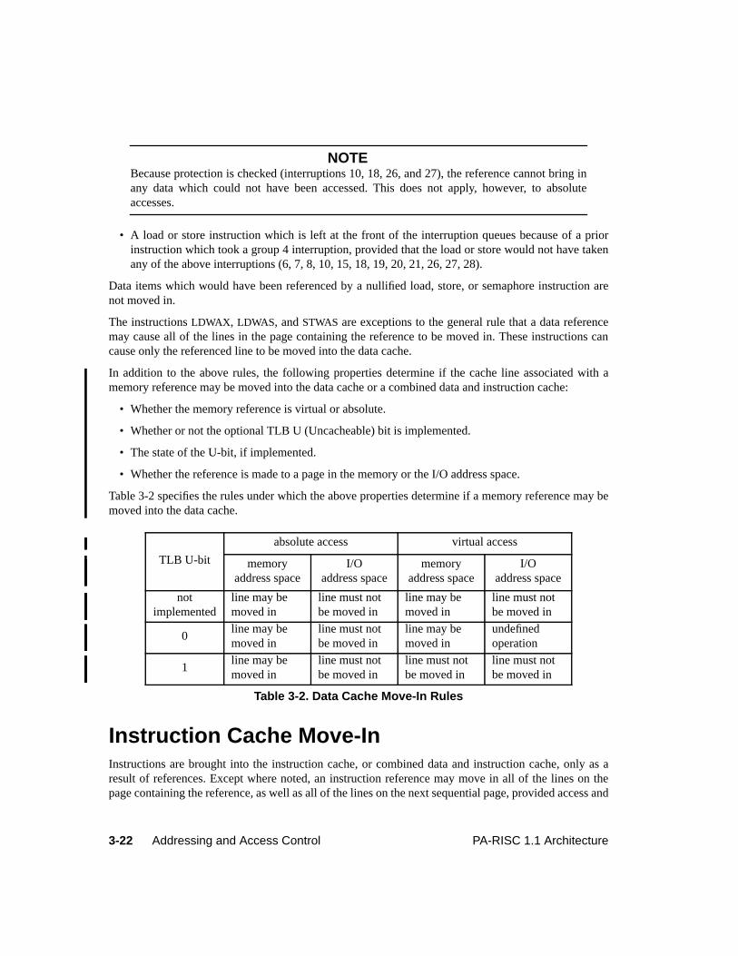
3-22 Addressing and Access Control PA-RISC 1.1 Architecture
NOTEBecause protection is checked (interruptions 10, 18, 26, and 27), the reference cannot bring inany data which could not have been accessed. This does not apply, however, to absoluteaccesses.
• A load or store instruction which is left at the front of the interruption queues because of a priorinstruction which took a group 4 interruption, provided that the load or store would not have takenany of the above interruptions (6, 7, 8, 10, 15, 18, 19, 20, 21, 26, 27, 28).
Data items which would have been referenced by a nullified load, store, or semaphore instruction arenot moved in.
The instructionsLDWAX , LDWAS, andSTWAS are exceptions to the general rule that a data referencemay cause all of the lines in the page containing the reference to be moved in. These instructions cancause only the referenced line to be moved into the data cache.
In addition to the above rules, the following properties determine if the cache line associated with amemory reference may be moved into the data cache or a combined data and instruction cache:
• Whether the memory reference is virtual or absolute.
• Whether or not the optional TLB U (Uncacheable) bit is implemented.
• The state of the U-bit, if implemented.
• Whether the reference is made to a page in the memory or the I/O address space.
Table 3-2 specifies the rules under which the above properties determine if a memory reference may bemoved into the data cache.
Instruction Cache Move-InInstructions are brought into the instruction cache, or combined data and instruction cache, only as aresult of references. Except where noted, an instruction reference may move in all of the lines on thepage containing the reference, as well as all of the lines on the next sequential page, provided access and
TLB U-bit
absolute access virtual access
memoryaddress space
I/Oaddress space
memoryaddress space
I/Oaddress space
notimplemented
line may bemoved in
line must notbe moved in
line may bemoved in
line must notbe moved in
0line may bemoved in
line must notbe moved in
line may bemoved in
undefinedoperation
1line may bemoved in
line must notbe moved in
line must notbe moved in
line must notbe moved in
Table 3-2. Data Cache Move-In Rules
3-23PA-RISC 1.1 Architecture Addressing and Access Control
protection check requirements are met for each page. (If the PSW C-bit is 0, then the next sequentialpage is the next sequential physical page. Otherwise, if the PSW C-bit is 1, then it is the next sequentialvirtual page.) The following actions constitute an instruction reference, and may cause move-in to theinstruction cache:
• Execution of an instruction
• Execution of a nullified instruction which would not have taken any of the following interruptionshad it not been nullified. This action can cause only those lines on the page containing theinstruction to be moved in
NOTEBecause protection is checked (interruption 7) the reference cannot bring in any instructionswhich could not be executed. This does not apply, however, to absolute accesses.
• Execution of a branch can cause all of the lines on the page containing the target of the branch to bemoved in.
• Execution of a branch to a target instruction which is the last instruction on a page, followed by aninstruction which traps (in the branch delay slot), can cause all of the lines on the page containingthe target instruction, as well as all of the lines on the next sequential page to be moved in.
• Interruption of an instruction by any interruption except for the ones listed below:
• A branch instruction which takes a group 4 interruption can cause all of the lines on the pagecontaining the instruction which would have been branched to, to be moved in.
Instructions which would have been branched to by nullified or untaken branches are not moved in.
If lines on the next sequential page are to be moved in, that page must meet the normal access andprotection check requirements.
PROGRAMMING NOTEIf a data page immediately follows an instruction page, it is possible that the entire data pagemay have been moved into the instruction cache because of these move-in rules. Softwaremust be aware of this fact and flushboth the instruction and the data caches in order toremove the data page from the cache.
Intr. No. Interruption
6 instruction TLB miss fault
7 instruction memory protection trap
Intr. No. Interruption
6 instruction TLB miss fault
7 instruction memory protection trap
3-24 Addressing and Access Control PA-RISC 1.1 Architecture
To insure that lines from a particular data page are not moved into the instruction cache,software must not make absolute instruction references to the immediately preceding physicalpage, and must prevent virtual instruction references to the data page. This latter can beaccomplished by not assigning execute access rights to the data page. If, however, the datapage is assigned execute access rights, and virtual instruction references are prevented by someother means, then software must also prevent virtual instruction references to the immediatelypreceding page.
In addition to the above rules, the following properties determine if the cache line associated with ainstruction reference may be moved into the instruction cache or a combined data and instruction cache:
• If the reference is made to a page in the memory address space, the referenced line may be movedinto the cache.
• If the reference is made to a page in the I/O address space, the referenced line must not be movedinto the cache.
• If there is a combined instruction and data TLB, then an instruction fetch from a page with its U-bit1 is undefined.
FlushingA flush cache, purge cache, or purge TLB instruction to a page stops (disables) any subsequent move-inoperations to that page until another reference to that page is made. In a multiprocessor system, theseinstructions stop any subsequent move-in operations to that page on all processors until anotherreference to that page is made.
Once a reference has been made, and a line could have been brought into a cache, the only way softwarecan insure that the line has been removed from the cache is to flush or purge it and execute aSYNCinstruction, or to flush the entire cache with flush-entry instructions and execute aSYNC instruction.Once a line is referenced, even if it is subsequently forced out of the cache by other references, thecache system can move it in again without another reference, until the line is flushed.
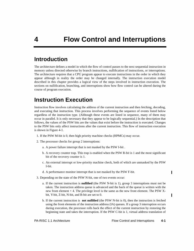
4-1PA-RISC 1.1 Architecture Flow Control and Interruptions
4 Flow Control and Interruptions
IntroductionThe architecture defines a model in which the flow of control passes to the next sequential instruction inmemory unless directed otherwise by branch instructions, nullification of instructions, or interruptions.The architecture requires that a CPU program appear to execute instructions in the order in which theyappear although in reality the order may be changed internally. The instruction execution modeldescribed in this chapter provides a logical view of the steps involved in instruction execution. Thesections on nullification, branching, and interruptions show how flow control can be altered during thecourse of program execution.
Instruction ExecutionInstruction flow involves calculating the address of the current instruction and then fetching, decoding,and executing that instruction. This process involves performing the sequence of events listed belowregardless of the instruction type. (Although these events are listed in sequence, many of them mayoccur in parallel. It is only necessary that they appear to be logically sequential.) In the description thatfollows, the values of the PSW bits are the values that exist before the instruction is executed. Changesto the PSW bits only affect instructions after the current instruction. This flow of instruction executionis shown in Figure 4-1.
1. If the PSW M-bit is 0, then high priority machine checks (HPMCs) may occur.
2. The processor checks for group 2 interruptions:
a. A power failure interrupt that is not masked by the PSW I-bit .
b. A recovery counter trap. This trap is enabled when the PSW R-bit is 1 and the most significantbit of the recovery counter is 1.
c. An external interrupt or low-priority machine check, both of which are unmasked by the PSWI-bit.
d. A performance monitor interrupt that is not masked by the PSW F-bit.
3. Depending on the state of the PSW N-bit, one of two events occur:
a. If the current instruction isnullified (the PSW N-bit is 1), group 3 interruptions must not betaken. The instruction address queue is advanced and the back of the queue is written with thenew front element + 4. The privilege level is the same as the new front element. The PSW X-bit, Y-bit, Z-bit, N-bit, and B-bit are set to 0.
b. If the current instruction is not nullified (the PSW N-bit is 0), then the instruction is fetchedusing the front elements of the instruction address (IA) queues. If a group 3 interruption occursduring execution, the processor rolls back the effect of the current instruction by restoring thebeginning state and takes the interruption. If the PSW C-bit is 1, virtual address translation of
4-2 Flow Control and Interruptions PA-RISC 1.1 Architecture
the instruction address is performed. The PSW P-bit enables protection checking. On a splitTLB system, the instruction TLB is used for instruction address translation. The fetching of thecurrent instruction may result in an instruction TLB miss fault/instruction page fault or aninstruction memory protection trap.
Figure 4-1. Interruption Processing
RFI
RFI
YESNO
YESNO
RFI RFI
Note: the solidline represents
the normalexecution path.
Dotted lineboxes describe
softwareactivities.
Fetch currentinstruction, performcurrent instruction,advance IA Queue
and RecoveryCounter, update
PSW.
group 3interruptionpending?
group 4interruptionpending?
group 2interruptionpending?
vector to highest-priority pending
group 4 interruption
process all pendinggroup 4
interruptions
vector to highestpriority pending
group 2 interruption
vector to highest-priority pending
group 3 interruption
back out effect ofcurrent instruction;backup recovery
counter, PSW, andIA queues.
process interruption
process interruption
YESNO
4-3PA-RISC 1.1 Architecture Flow Control and Interruptions
The Recovery Counter is decremented if the PSW R-bit is 1. The current instruction isexecuted and the PSW X-bit, Y-bit, and Z-bit are set to 0. If the next instruction is to benullified, the PSW N-bit is set to 1, and the instruction address queues are updated. The natureof that update depends on whether the current instruction is a taken branch:
• For a taken branch: the instruction address queues are advanced, the back of the queue isloaded with the target address including the privilege level which is computed by thebranch instruction, and the PSW B-bit is set to 1.
• For a branch that is not taken: the instruction address queues are advanced, the back of theinstruction address offset queue is written with the new front element + 4, the privilegelevel of the back element is set the same as the new front element, and the PSW B-bit isset to 0.
• If the current instruction is aRETURN FROM INTERRUPTION or RETURN FROMINTERRUPTION AND RESTORE instruction, the IA queues and the PSW are updated withthe new values and the following instruction is executed based on these new values.
4. Group 4 traps are handled after execution is complete. If the new privilege level is lower than thatof the just completed instruction and the PSW L-bit was 1, a lower-privilege transfer trap is taken.If the new privilege level is higher than that of the just completed instruction and the PSW H-bitwas 1, a higher-privilege transfer trap is taken. The term "new privilege" level refers to theprivilege level at which the following instruction executes.
If neither transfer trap is taken, the instruction just completed is a taken branch, and the PSW T-bitwas 1, then a taken branch trap occurs.
Atomicity of Storage AccessesAll load and semaphore instructions access storage atomically. All store instructions, exceptSTOREBYTES SHORT when accessing the I/O address space, access storage atomically. For example, a double-word load instruction executing on one processor concurrently with a double-word store instruction tothe same address executing on another processor will receive either the entire old value or the entirenew value.
Ordering of AccessesAccesses to the address space (both to memory and I/O) through load, store, and semaphore instructionsare strongly ordered. This means that accesses appear to software to be done in program order. Inmultiprocessor systems, accesses by a given processor must appear to that processor, as well as to allother processors in the system, to be done in program order.
If processor A executes a load instruction and receives the value stored by a store instruction executedon processor B, then processor A is said to haveobserved the store by processor B.
If a store by a processor is observed by another processor or by an I/O module, then the store is said tobeperformed.

4-4 Flow Control and Interruptions PA-RISC 1.1 Architecture
NOTEAn example of the observability of the ordering of accesses can be seen by considering twoprocesses, A and B, running concurrently on a multiprocessor system.
If process B observes A’s store to y, then process B may rely on the fact that its store to x willnot affect the value seen by process A.
This strong ordering applies to I/O accesses as well. For example, the sequence of an I/O accessfollowed by a memory access appears to be performed in program order.
Cache flush operations are, however, not strongly ordered. Flush operations may be delayed or heldpending, and a sequence of flush operations may be executed in any order. TheSYNC instruction is usedto ensure ordering. TheSYNC instruction enforces the ordering of only those accesses caused by theinstructions executed on the same processor which executes theSYNC instruction. After executing aSYNC instruction, any pending flush operations are completed before performing any subsequent load,store, semaphore, flush, or purge instructions. Flush operations do get performed, however, prior to asubsequent purge operation to the same cache line, to prevent loss of data. In multiprocessor systems, toallow non-privileged code to do cache management, system software must execute aSYNC instructionwhen switching processes.
Cache purge operations are strongly ordered, but only with respect to accesses to the same cache line. ASYNC instruction ensures ordering with respect to subsequent accesses.
PROGRAMMING NOTESoftware which executes Purge Data Cache instructions to memory locations which are sharedwith other processes must be aware of a potential problem. Consider two processes sharing amemory locationx which is protected by a semaphores.
In the absence of the SYNC instruction, it is possible that process B stores tox before the purgeis actually completed.
process A process B
load x load y
store y store x
process A on Processor 1 process B on Processor 2 note
LDCW s A acquires semaphore
PDC x A executes purge
SYNC Force completion of purge
STW s A releases semaphore
LDCW s B acquires semaphore
STW x
4-5PA-RISC 1.1 Architecture Flow Control and Interruptions
MTCTL and MFCTL instructions involving the EIR and the EIEM must appear to preserve programorder.
Modification of resources which affect data access take effect immediately. Acknowledgement of a dataTLB purge request from another processor must not be made until after the purge has logically beenperformed. Data access resources include Protection Identifier Registers, PSW, and TLB entries.
Interrupts must be masked immediately following a MTCTL to the EIEM register that masks interruptsor an RSM or MTSM that sets the PSW I-bit to 0.
Completion of AccessesPA-RISC processors are inherently asynchronous and software may not rely on instruction timing forcorrect operation. Implementations are permitted to execute instructions out of order and need onlypreserve the appearance of sequential execution. For example, in the absence of other constraints whichwould force execution, flush and purge operations may be indefinitely delayed. To insure that progressis made, however, the following requirements must be met.
• Instruction streams must make forward progress. This means that any operation, on which aninstruction stream is dependent, must be performed in some finite period.
• All load and store operations to the I/O space must be performed in some finite period.
• Execution of aSYNC instruction forces all prior flush operations from the same instruction streamto be performed in some finite period.
For performance and testability reasons, it is occasionally necessary to know when an access to I/Ospace has completed. This would not normally be possible due to the asynchronous nature of execution.In order to provide this capability, the following two special sequences are defined. These sequencesplace additional requirements on implementations for the completion of accesses. When these codesequences are used, the additional completion requirements hold.
When this code sequence is executed, the instruction labeled ‘access A completed on bus’ is notexecuted, and the source registers not read until after the LDW (or STW) labeled ‘access A’ hascompleted on the bus.
When this code sequence is executed, the instruction labeled ‘access B completed on module’ is notexecuted, and the source registers not read until after the STW instruction labeled ‘access B’ hascompleted on the I/O module.
LDW (or STW) from (to) I/O space ; access A
SYNC
LDW from I/O space, but not to GR 0
(at least seven instructions)
Instruction ; access A completed on bus
4-6 Flow Control and Interruptions PA-RISC 1.1 Architecture
Instruction PipeliningThe architecture permits implementations to prefetch up to seven instructions from the cache (includingbranch prediction) beyond the instruction currently executing. Instructions may modify resources whichaffect instruction fetch on the machine they are executing on. Instruction fetch resources includeprotection identifier registers, the PSW, and TLB entries. When such an event takes place, it affectsinstructions that are fetched 8 instructions later (at the latest), or after the nextRETURN FROMINTERRUPTION or RETURN FROM INTERRUPTION AND RESTORE instruction, whichever occurs first.
Instructions may also modify resources on other processors in a multiprocessor system, which affect theinstruction fetch of the target processors. When such an event takes place (the modification of theresource is acknowledged), it affects instructions that are fetched, on the target processors, after theyhave finished executing 8 instructions (at the latest) except as noted below.
When a processor executes an instruction which purges an instruction TLB entry in other processors,the target processors must acknowledge completing the purge. The target processors may not completea move-in, which was initiated using the purged translation, after acknowledging the removal.Acknowledgement of a data TLB purge request from another processor must not be made until after thepurge has logically been performed.
Modification of code, while discouraged, may be performed using the following protocol:
1. Modify the code in the data cache.
2. Flush the modified code from the data cache.
3. Issue aSYNCHRONIZE CACHES instruction to ensure the flush is completed and subsequent move-in will observe the memory version.
4. Flush the location of the modified code from the instruction cache.
5. Issue aSYNCHRONIZE CACHES instruction to ensure the flush is completed.
6. Delay at least an additional seven instructions or execute aRETURN FROM INTERRUPTION orRETURN FROM INTERRUPTION AND RESTORE instruction.
In a multiprocessor system, software must ensure that no other processor is executing code that is in theprocess of being modified.
STW to I/O space ; access B
LDW from the same I/O space module
SYNC
LDW from I/O space, but not to GR 0
(at least seven instructions)
Instruction ; access B completed on module
4-7PA-RISC 1.1 Architecture Flow Control and Interruptions
NullificationA nullified instruction is an instruction that is skipped over. It has no effect on the machine state (exceptthat the IA queues advance and the B-bit, N-bit, X-bit, Y-bit, and Z-bit in the PSW are set to 0). Therecovery counteris not decremented for a nullified instruction. Nullified instructions do not take group3 interruptions (although they may take group 1, 2, or 4 interruptions).
All branch instructions and computational instructions can nullify the execution of the followinginstruction. For branch instructions, nullification can be specified explicitly. In the case ofcomputational instructions, nullification is performed conditionally based on the outcome of a test.
BranchingBranches are another way of altering the flow during program execution. The architecture provides bothunconditional and conditional branch instructions. Unconditional branch instructions always branch tothe specified target. Conditional branch instructions first perform some operation (move, compare, add,or bit test) and then branch if the outcome of the specified condition is met.
Concept of Delayed BranchingAll branch instructions exhibit the delayed branch feature. This implies that the major effect of thebranch instruction, the actual transfer of control, occurs one instruction after the execution of thebranch. As a result, the instruction following the branch (located in thedelay slot of the branchinstruction) is executed before control passes to the branch destination. The concept of delayedbranching is illustrated in Figure 4-2.
Execution of the delay slot instruction, however, may be skipped ("nullified") by setting the "nullify" bitin the branch instruction to 1.
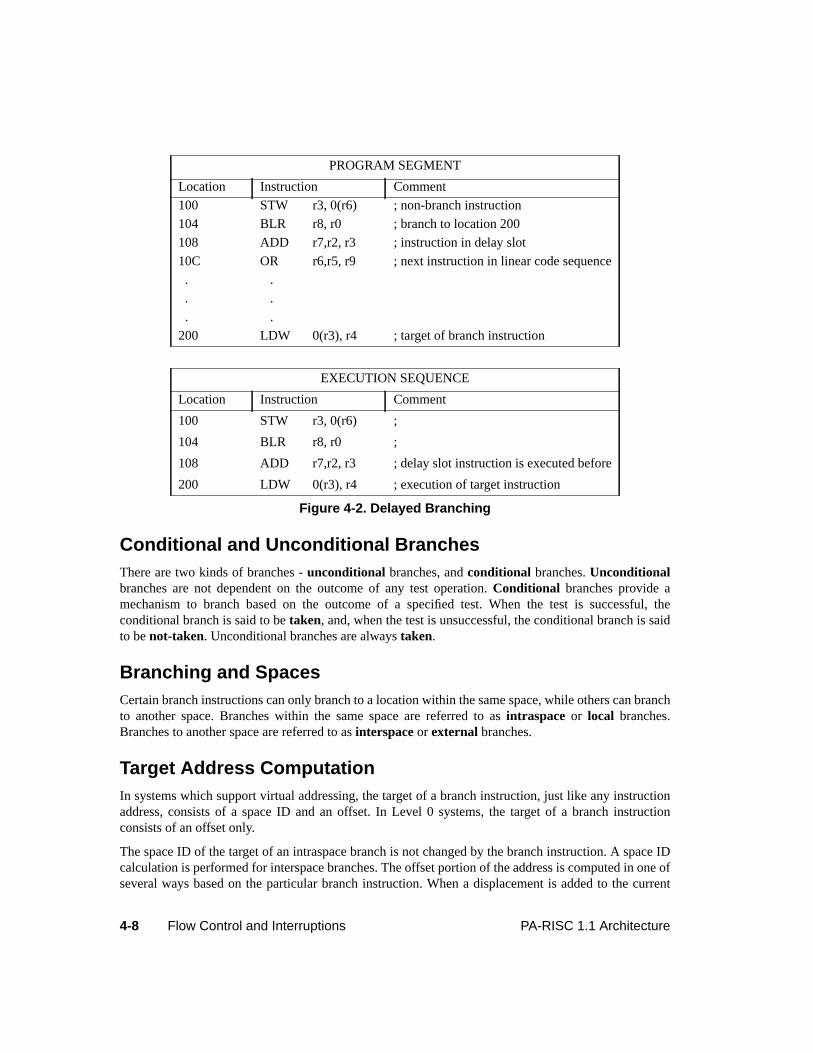
4-8 Flow Control and Interruptions PA-RISC 1.1 Architecture
Conditional and Unconditional BranchesThere are two kinds of branches -unconditional branches, andconditional branches.Unconditionalbranches are not dependent on the outcome of any test operation.Conditional branches provide amechanism to branch based on the outcome of a specified test. When the test is successful, theconditional branch is said to betaken, and, when the test is unsuccessful, the conditional branch is saidto benot-taken. Unconditional branches are alwaystaken.
Branching and SpacesCertain branch instructions can only branch to a location within the same space, while others can branchto another space. Branches within the same space are referred to asintraspace or local branches.Branches to another space are referred to asinterspace or external branches.
Target Address ComputationIn systems which support virtual addressing, the target of a branch instruction, just like any instructionaddress, consists of a space ID and an offset. In Level 0 systems, the target of a branch instructionconsists of an offset only.
The space ID of the target of an intraspace branch is not changed by the branch instruction. A space IDcalculation is performed for interspace branches. The offset portion of the address is computed in one ofseveral ways based on the particular branch instruction. When a displacement is added to the current
PROGRAM SEGMENT
Location Instruction Comment
100 STW r3, 0(r6) ; non-branch instruction
104 BLR r8, r0 ; branch to location 200
108 ADD r7,r2, r3 ; instruction in delay slot
10C OR r6,r5, r9 ; next instruction in linear code sequence
. .
. .
. .
200 LDW 0(r3), r4 ; target of branch instruction
EXECUTION SEQUENCE
Location Instruction Comment
100 STW r3, 0(r6) ;
104 BLR r8, r0 ;
108 ADD r7,r2, r3 ; delay slot instruction is executed before
200 LDW 0(r3), r4 ; execution of target instruction
Figure 4-2. Delayed Branching
4-9PA-RISC 1.1 Architecture Flow Control and Interruptions
instruction address offset, the branch is calledIA relative . When a general register is used as a baseoffset, it is calledbase relative. Also, if the displacement is a fixed value that is known at compilation,it is known asstatic displacement. If the value is computed during the course of program execution, andis read from a general register, it is known asdynamic displacement.
For interspace branches, the space ID of the target address is always specified in a space register, and iscopied into the IASQ when the branch is performed. The offset of the target is computed by adding a17-bit signed word displacement to the base register specified in a general register. The two rightmostbits in the base register denote the new privilege level and are ignored during the offset computation.Also, the 17-bit signed word displacement is shifted left by two before adding to the base register.Interspace branches are always base relative.
In the case of intraspace branches, the space ID is not changed by the branch. The offset of the target,however, can be computed in one of three ways. For IA relative branches with static displacement, a 12-bit or 17-bit signed word displacement is shifted left by two and added to the current instruction addressoffset plus eight. For IA relative branches with dynamic displacement, the value specified in the indexregister is shifted left by three and added to current instruction address offset plus eight. For baserelative branches with dynamic displacement, the value specified in the index register is shifted left bythree and added to the value in the specified base register.
It should be noted that for IA relative branches, the target is computed from the current instruction byadding a displacement or an index value. Since the instruction in the delay slot must be executed if it isnot nullified, an additional value of eight is added in the offset computation to arrive at the targetcorrectly. This is done to ensure that a branch with a displacement of zero will branch to the instructionfollowing the delayed instruction. Also, this helps users build case tables immediately following thedelay slot instruction.
Privilege Level ChangesBranch instructions may change the privilege level depending on the type of branch performed. Sinceprivilege levels are determined by the two rightmost bits in the offset part of the instruction address,privilege level changes are a function of the offset computation.
Unconditional branches can be IA relative or base relative. IA relative branches compute the targetaddress relative to their own IA value, and since the two rightmost bits are unchanged, the privilegelevel of the branch instruction and the target are the same. Base relative branches (intraspace orinterspace) may lower the privilege level if the two rightmost bits in the base register are of a lowerprivilege level. TheGATEWAY instruction is an IA relative branch, however, it behaves differently forprivilege computation. It can promote the privilege level to that specified by the two rightmost bits ofthetype field, located in the TLB entry for the page from which theGATEWAY instruction is fetched. InLevel 0 systems, execution of aGATEWAY instruction causes the privilege level to be promoted to 0.
Conditional branch instructions always perform IA relative branches and the privilege level of the targetinstruction and the branch instruction is the same.
The change of privilege level takes effect at the target instruction except in the case of theGATEWAY.Change of privilege level for aGATEWAY instruction can occur either at the delay slot or the targetinstruction.
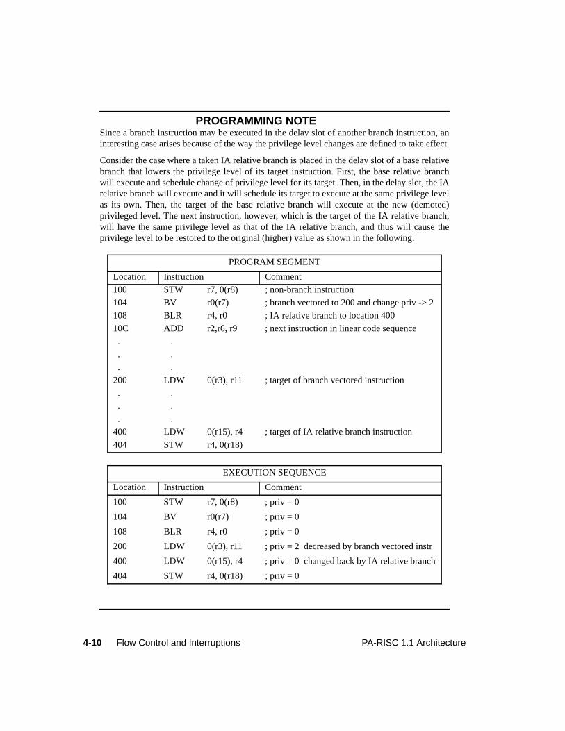
4-10 Flow Control and Interruptions PA-RISC 1.1 Architecture
PROGRAMMING NOTESince a branch instruction may be executed in the delay slot of another branch instruction, aninteresting case arises because of the way the privilege level changes are defined to take effect.
Consider the case where a taken IA relative branch is placed in the delay slot of a base relativebranch that lowers the privilege level of its target instruction. First, the base relative branchwill execute and schedule change of privilege level for its target. Then, in the delay slot, the IArelative branch will execute and it will schedule its target to execute at the same privilege levelas its own. Then, the target of the base relative branch will execute at the new (demoted)privileged level. The next instruction, however, which is the target of the IA relative branch,will have the same privilege level as that of the IA relative branch, and thus will cause theprivilege level to be restored to the original (higher) value as shown in the following:
PROGRAM SEGMENT
Location Instruction Comment
100 STW r7, 0(r8) ; non-branch instruction
104 BV r0(r7) ; branch vectored to 200 and change priv -> 2
108 BLR r4, r0 ; IA relative branch to location 400
10C ADD r2,r6, r9 ; next instruction in linear code sequence
. .
. .
. .
200 LDW 0(r3), r11 ; target of branch vectored instruction
. .
. .
. .
400 LDW 0(r15), r4 ; target of IA relative branch instruction
404 STW r4, 0(r18)
EXECUTION SEQUENCE
Location Instruction Comment
100 STW r7, 0(r8) ; priv = 0
104 BV r0(r7) ; priv = 0
108 BLR r4, r0 ; priv = 0
200 LDW 0(r3), r11 ; priv = 2 decreased by branch vectored instr
400 LDW 0(r15), r4 ; priv = 0 changed back by IA relative branch
404 STW r4, 0(r18) ; priv = 0
4-11PA-RISC 1.1 Architecture Flow Control and Interruptions
LinkageLinkage is provided in certain branch instructions to allow a return path for procedure calls. The returnpoint is four bytes after the following instruction. Since the execution of all branches is followed by theexecution of the instruction in the delay slot (or null if nullified), it should be noted that the return pointis always specified as four bytes after the following instruction andnot eight bytes after theBRANCHAND LINK instruction. When the following instruction is not spatially sequential, then four bytes afterthe following instruction is not the same as eight bytes after theBRANCH AND LINK instruction.
The linkage mechanism is available for both intraspace and interspace branches. For intraspacebranches, the offset of the return point is saved in the specified target register GR t. For interspacebranches, the offset of the return point is always saved in GR 31, and the space ID of the return point issaved in SR 0 (except in Level 0 systems where SR 0 is nonexistent).
Conditional Branching and NullificationWhen nullification is specified by a conditional branch instruction, the effect of nullification depends onthe direction of the branch. This maximizes useful work done during loops and "if-then" constructs.
For a backward conditional branch, the following instruction is nullified only when the backwardconditional branch isnot taken. For forward conditional branches, the following instruction is nullifiedonly when the forward conditional branchis taken. For unconditional branches, if nullification isspecified, the following instruction is nullifiedindependent of the direction of branch.
Branching and Address QueuesThe concept of delayed branching makes it necessary to maintain the instruction address (IA) in a pairof two element queues. Thefront elements point to the currently executing instruction and thebackelements point to the following instruction that will be executed. The termnext refers to the SpaceIdentifier and the offset of the next instruction address, which will enter the back elements of the queueswhen the queues are updated. The queues are said to be updated when theback elements become thefront andnext become theback elements.
For taken branches, the IA queues get updated with the address of the branch target. Both the wordoffset and the privilege level are updated. IAOQ_Next receives the value of the branch target offset. Fornot-taken branches, IAOQ_Next gets IAOQ_Back + 4. The privilege level is obtained from the backelement of the queue. For external branches (BE and BLE), IASQ_Next gets the value of the branchtarget Space ID. Otherwise, IASQ_Next receives the content of IASQ_Back. Figure 4-3 shows how theIA queues are updated, using a pseudo-code representation.
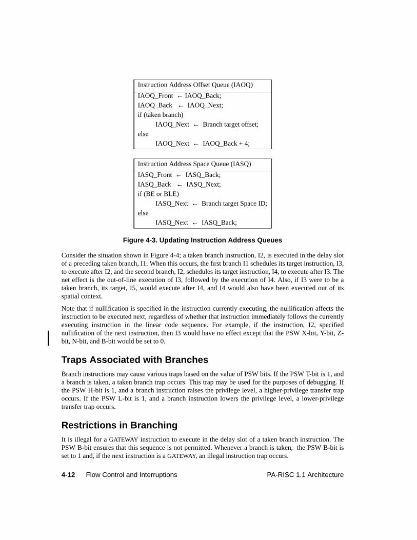
4-12 Flow Control and Interruptions PA-RISC 1.1 Architecture
Figure 4-3. Updating Instruction Address Queues
Consider the situation shown in Figure 4-4; a taken branch instruction, I2, is executed in the delay slotof a preceding taken branch, I1. When this occurs, the first branch I1 schedules its target instruction, I3,to execute after I2, and the second branch, I2, schedules its target instruction, I4, to execute after I3. Thenet effect is the out-of-line execution of I3, followed by the execution of I4. Also, if I3 were to be ataken branch, its target, I5, would execute after I4, and I4 would also have been executed out of itsspatial context.
Note that if nullification is specified in the instruction currently executing, the nullification affects theinstruction to be executed next, regardless of whether that instruction immediately follows the currentlyexecuting instruction in the linear code sequence. For example, if the instruction, I2, specifiednullification of the next instruction, then I3 would have no effect except that the PSW X-bit, Y-bit, Z-bit, N-bit, and B-bit would be set to 0.
Traps Associated with BranchesBranch instructions may cause various traps based on the value of PSW bits. If the PSW T-bit is 1, anda branch is taken, a taken branch trap occurs. This trap may be used for the purposes of debugging. Ifthe PSW H-bit is 1, and a branch instruction raises the privilege level, a higher-privilege transfer trapoccurs. If the PSW L-bit is 1, and a branch instruction lowers the privilege level, a lower-privilegetransfer trap occurs.
Restrictions in BranchingIt is illegal for aGATEWAY instruction to execute in the delay slot of a taken branch instruction. ThePSW B-bit ensures that this sequence is not permitted. Whenever a branch is taken, the PSW B-bit isset to 1 and, if the next instruction is aGATEWAY, an illegal instruction trap occurs.
Instruction Address Offset Queue (IAOQ)
IAOQ_Front ← IAOQ_Back;
IAOQ_Back ← IAOQ_Next;
if (taken branch)
IAOQ_Next ← Branch target offset;
else
IAOQ_Next ← IAOQ_Back + 4;
Instruction Address Space Queue (IASQ)
IASQ_Front ← IASQ_Back;
IASQ_Back ← IASQ_Next;
if (BE or BLE)
IASQ_Next ← Branch target Space ID;
else
IASQ_Next ← IASQ_Back;
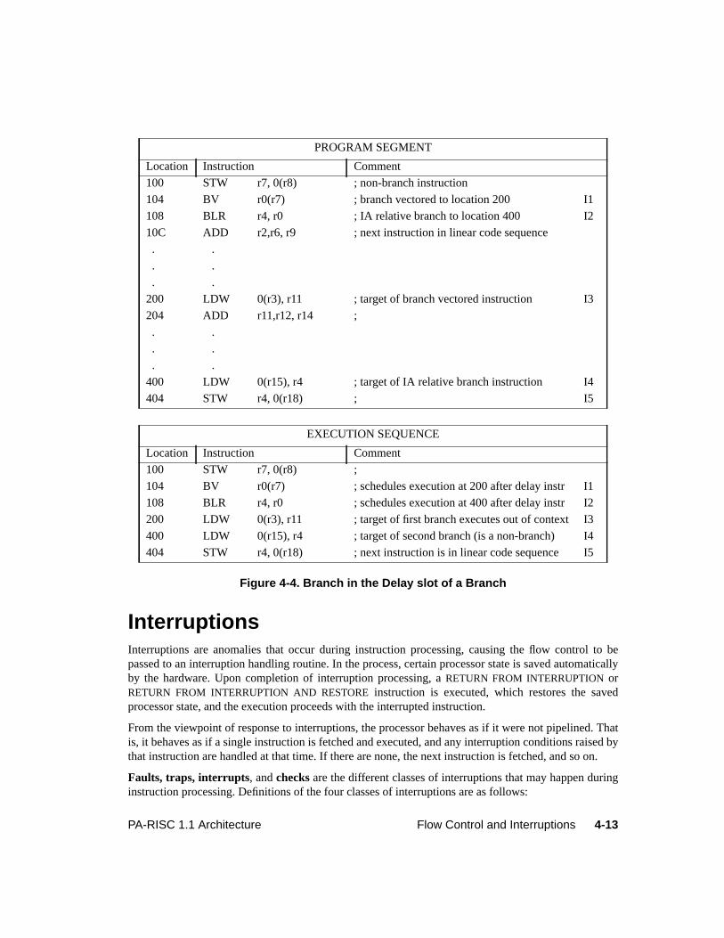
4-13PA-RISC 1.1 Architecture Flow Control and Interruptions
Figure 4-4. Branch in the Delay slot of a Branch
InterruptionsInterruptions are anomalies that occur during instruction processing, causing the flow control to bepassed to an interruption handling routine. In the process, certain processor state is saved automaticallyby the hardware. Upon completion of interruption processing, aRETURN FROM INTERRUPTION orRETURN FROM INTERRUPTION AND RESTORE instruction is executed, which restores the savedprocessor state, and the execution proceeds with the interrupted instruction.
From the viewpoint of response to interruptions, the processor behaves as if it were not pipelined. Thatis, it behaves as if a single instruction is fetched and executed, and any interruption conditions raised bythat instruction are handled at that time. If there are none, the next instruction is fetched, and so on.
Faults, traps, interrupts, andchecks are the different classes of interruptions that may happen duringinstruction processing. Definitions of the four classes of interruptions are as follows:
PROGRAM SEGMENT
Location Instruction Comment
100 STW r7, 0(r8) ; non-branch instruction
104 BV r0(r7) ; branch vectored to location 200 I1
108 BLR r4, r0 ; IA relative branch to location 400 I2
10C ADD r2,r6, r9 ; next instruction in linear code sequence
. .
. .
. .
200 LDW 0(r3), r11 ; target of branch vectored instruction I3
204 ADD r11,r12, r14 ;
. .
. .
. .
400 LDW 0(r15), r4 ; target of IA relative branch instruction I4
404 STW r4, 0(r18) ; I5
EXECUTION SEQUENCE
Location Instruction Comment
100 STW r7, 0(r8) ;
104 BV r0(r7) ; schedules execution at 200 after delay instr I1
108 BLR r4, r0 ; schedules execution at 400 after delay instr I2
200 LDW 0(r3), r11 ; target of first branch executes out of context I3
400 LDW 0(r15), r4 ; target of second branch (is a non-branch) I4
404 STW r4, 0(r18) ; next instruction is in linear code sequence I5
4-14 Flow Control and Interruptions PA-RISC 1.1 Architecture
Fault The current instruction requests a legitimate action which cannot be carried out due toa system problem, such as the absence of a page from main memory. After the systemproblem has been corrected, the faulting instruction will execute normally. Faults aresynchronous with respect to the instruction stream.
Trap Traps include two sorts of possibilities: either the function requested by the currentinstruction cannot or should not be carried out, or system intervention is desired bythe user before or after the instruction is executed. Examples of the first type includearithmetic operations that result in signed overflow and instructions executed withinsufficient privilege for their intended function. Such instructions are normally notre-executed. Examples of the second type include the debugging support traps. Trapsare synchronous with respect to the instruction stream.
Interrupt An external entity (e.g., an I/O device or the power supply) requires attention.Interrupts are asynchronous with respect to the instruction stream.
Check The processor has detected an internal malfunction. Checks can be eithersynchronous or asynchronous with respect to the instruction stream.
All four classes of interruptions are handled in the same way. The interruptions are categorized into fourgroups based on their priorities:
Group 1: 1 High-priority machine check
Group 2: 2 Power failure interrupt
3 Recovery counter trap
4 External interrupt
5 Low-priority machine check
29 Performance monitor interrupt
Group 3: 6 Instruction TLB miss fault/Instruction page fault
7 Instruction memory protection trap
30 Instruction debug trap
8 Illegal instruction trap
9 Break instruction trap
10 Privileged operation trap
11 Privileged register trap
12 Overflow trap
13 Conditional trap
14 Assist exception trap
15 Data TLB miss fault/Data page fault
16 Non-access instruction TLB miss fault
17 Non-access data TLB miss fault/Non-access data page fault
26 Data memory access rights trap
27 Data memory protection ID trap
28 Unaligned data reference trap
4-15PA-RISC 1.1 Architecture Flow Control and Interruptions
The interruption numbers in the above list are the individual vector numbers that determine whichinterruption handler is invoked for each interruption. The group numbers determine when the particularinterruption will be processed during the course of instruction execution. The order the interruptions arelisted within each group (not the interruption numbers) determines the priority of simultaneousinterruptions (from highest to lowest).
Interruption HandlingInterruption handling is implemented as a fast context switch (much simpler than a complete processswap). When an interruption occurs, the hardware takes the following actions:
1. The PSW in effect at the time of the interruption is saved in the IPSW. For group 2 and 3interruptions, the saved PSW is the value at the beginning of execution. For group 4 interruptions,the saved PSW is the value after the execution of the instruction.
2. The defined bits in the PSW are set as follows:
E Set to the value of the default endian bit.
M Set to 1 if the interruption is a high-priority machine check; otherwise, set to 0.
all other bits Set to 0 (interrupts are masked, absolute accesses are enabled, etc.).
3. IA information in the IIA queues is frozen (as a result of setting the PSW Q-bit to 0 in step 2above).
In order to enable restarting of instructions in the presence of delayed branching, at least twoaddresses must be saved, pointing to the next two instructions to be executed after returning fromthe interruption. The hardware, therefore, maintains IIA Space and IIA Offset queues, which havetwo elements and contain the addresses and privilege levels of these instructions. The IIA queuesare kept up-to-date whenever the Q-bit in the PSW is 1. When an interruption is taken, theaddresses of the pending instructions are preserved in the queues. The elements of the queues maybe obtained by reading the IIASQ and IIAOQ registers (CRs 17 and 18, respectively).
4. The current privilege level is set to the highest privilege level (zero).
5. Information about the interrupting instruction is saved in the IPRs if the PSW Q-bit was 1 at thetime of the interruption. If the PSW Q-bit was 0, the IPRs are unchanged. If the details of aninstruction associated with the interruption are potentially useful in processing it, the instruction is
18 Data memory protection trap/Unaligned data reference trap
19 Data memory break trap
20 TLB dirty bit trap
21 Page reference trap
31 Data debug trap
22 Assist emulation trap
Group 4: 23 Higher-privilege transfer trap
24 Lower-privilege transfer trap
25 Taken branch trap
4-16 Flow Control and Interruptions PA-RISC 1.1 Architecture
loaded into the Interruption Instruction Register (IIR or CR 19). If there is an address associatedwith the interruption, it is loaded into the Interruption Space and Interruption Offset registers (ISRor CR 20, and IOR or CR 21). When data address translation is not enabled, the ISRs contents areundefined. The value loaded into the IOR includes all 32 bits of the offset.
6. General registers 1, 8, 9, 16, 17, 24, and 25 are copied to the shadow registers.
7. Execution begins at the address given by:
Interruption Vector Address + (32 * interruption_number)
Interruption_number is the unique integer value assigned to that particular interruption. Vectoringis accomplished by performing an indexed branch into the Interruption Vector Table indexed bythis integer. The Interruption Vector Table contains the starting points of execution of theinterruption handling routines. The value in the Interruption Vector Address register (CR 14) mustbe aligned on a 2 Kbyte boundary.
PROGRAMMING NOTEIt is the responsibility of interruption handlers to unmask external interrupts (by setting thePSW I-bit to 1) as soon as possible, so as to minimize the worst-case latency of externalinterrupts.
Instruction RecoverabilityWhen execution of instructions is interrupted, the minimal processor state that is required to be savedand restored is that necessary to correctly continue execution of the instruction stream followingprocessing of the interruption. Processor state is defined to include any register contents, PSW bits, orother information that may affect the operation performed by an instruction. For example, if aninterruption is taken immediately before anADD instruction, its source registers must be restored, butits target register need not be (unless it is also one of the source registers).
Masking and Nesting of InterruptionsDisabling an interruption prevents it from occurring. The interruption does not wait until re-enabled. Itis not kept pending.Masking an interruption does not prevent the recognition of a pending interruptioncondition, but delays the occurrence of the interruption until it is "unmasked".
The IA state is collected in the IIA queues only while the PSW Q-bit is 1; it is usually not possible toresume execution after an interruption which is taken while the PSW Q-bit is 0.
The machine state is saved in registers rather than memory when an interruption occurs, andinterruption handlers must leave interruptions disabled until they have saved the machine state inmemory. Once the machine state is saved, nested interrupts can be allowed.
Since it is desirable to catch hardware faults as soon as possible, interruption handlers should generallynot mask high-priority machine checks. If a machine check occurs before the machine state has beensaved, the interrupted process may need to be aborted. The occurrence of traps and faults withininterruption handlers can be avoided by careful writing of the handlers.
4-17PA-RISC 1.1 Architecture Flow Control and Interruptions
Interruption PrioritiesHigh-priority machine checks (which belong to Group 1) may occur and be processed at any time. Theymay be synchronous or asynchronous with instruction processing, may be associated with more thanone instruction, and their precise meaning and processing is implementation dependent.
All interruptions other than high-priority machine checks are taken between instructions. Multiplesimultaneous interruptions may occur because a number of instructions are capable of raising severalsynchronous interruptions simultaneously, and because certain interruptions are asynchronous withrespect to the instruction stream.
Group 2 interruptions occur asynchronously with respect to the instruction stream.
Group 3 interruptions are synchronous with respect to the instruction stream and are signalled beforecompletion of the instruction that produces them.
Group 4 interruptions are synchronous with respect to the instruction stream and are signalled eitherafter completion of the instruction that causes them, or when a change in privilege level is about tohappen.
Relative priorities are not assigned to the 32 external interrupts by the hardware. When multipleexternal interrupts occur simultaneously, software may select their order of service, based on thecontents of EIR.
Return from InterruptionTheRETURN FROM INTERRUPTION andRETURN FROM INTERRUPTION AND RESTORE instructionsrestore the PSW and instruction address queues. If the old PSW stored in IPSW (CR 22) hasinterruptions enabled (or unmasked), interruptions are re-enabled before execution of the first of thecontinuation instructions. The PSW Q-bit may be set to 1 reliably only by aRETURN FROMINTERRUPTION or RETURN FROM INTERRUPTION AND RESTORE instruction. An attempt to set thePSW Q-bit to 1 with aSET SYSTEM MASK or MOVE TO SYSTEM MASK instruction is an undefinedoperation.
The RETURN FROM INTERRUPTION AND RESTORE instruction does everything that theRETURNFROM INTERRUPTION instruction does, and in addition causes the values in the shadow registers to becopied to GRs 1, 8, 9, 16, 17, 24, and 25. Execution of aRETURN FROM INTERRUPTION ANDRESTORE instruction leaves the contents of the shadow registers undefined.
Executing aRETURN FROM INTERRUPTION or a RETURN FROM INTERRUPTION AND RESTOREinstruction with the PSW Q-bit 0 and the IPSW Q-bit 0 leaves the IPRs unchanged.
PROGRAMMING NOTEOnly those interruptions which are themselves uninterruptible may return from the interruptionusing theRFIR instruction. Interruption handling code which is interruptible must return fromthe interruption using theRFI instruction.
Fast interruption handling is achieved using shadow registers, since GRs 1, 8, 9, 16, 17, 24,and 25 are copied to the shadow registers on interruptions. In this example, it is assumed that atmost seven general registers need to be used in the interruption handling routine.
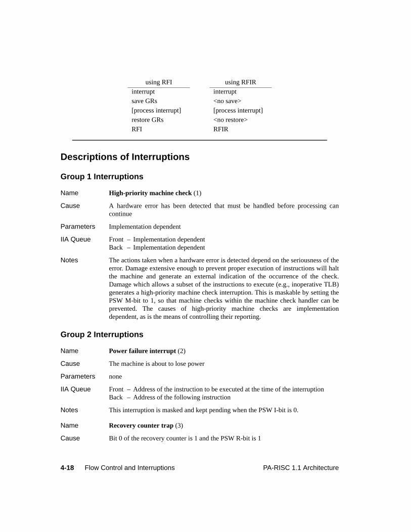
4-18 Flow Control and Interruptions PA-RISC 1.1 Architecture
Descriptions of Interruptions
Group 1 Interruptions
Name High-priority machine check (1)
Cause A hardware error has been detected that must be handled before processing cancontinue
Parameters Implementation dependent
IIA Queue Front – Implementation dependentBack – Implementation dependent
Notes The actions taken when a hardware error is detected depend on the seriousness of theerror. Damage extensive enough to prevent proper execution of instructions will haltthe machine and generate an external indication of the occurrence of the check.Damage which allows a subset of the instructions to execute (e.g., inoperative TLB)generates a high-priority machine check interruption. This is maskable by setting thePSW M-bit to 1, so that machine checks within the machine check handler can beprevented. The causes of high-priority machine checks are implementationdependent, as is the means of controlling their reporting.
Group 2 Interruptions
Name Power failure interrupt (2)
Cause The machine is about to lose power
Parameters none
IIA Queue Front – Address of the instruction to be executed at the time of the interruptionBack – Address of the following instruction
Notes This interruption is masked and kept pending when the PSW I-bit is 0.
Name Recovery counter trap (3)
Cause Bit 0 of the recovery counter is 1 and the PSW R-bit is 1
using RFI using RFIR
interrupt interrupt
save GRs <no save>
[process interrupt] [process interrupt]
restore GRs <no restore>
RFI RFIR
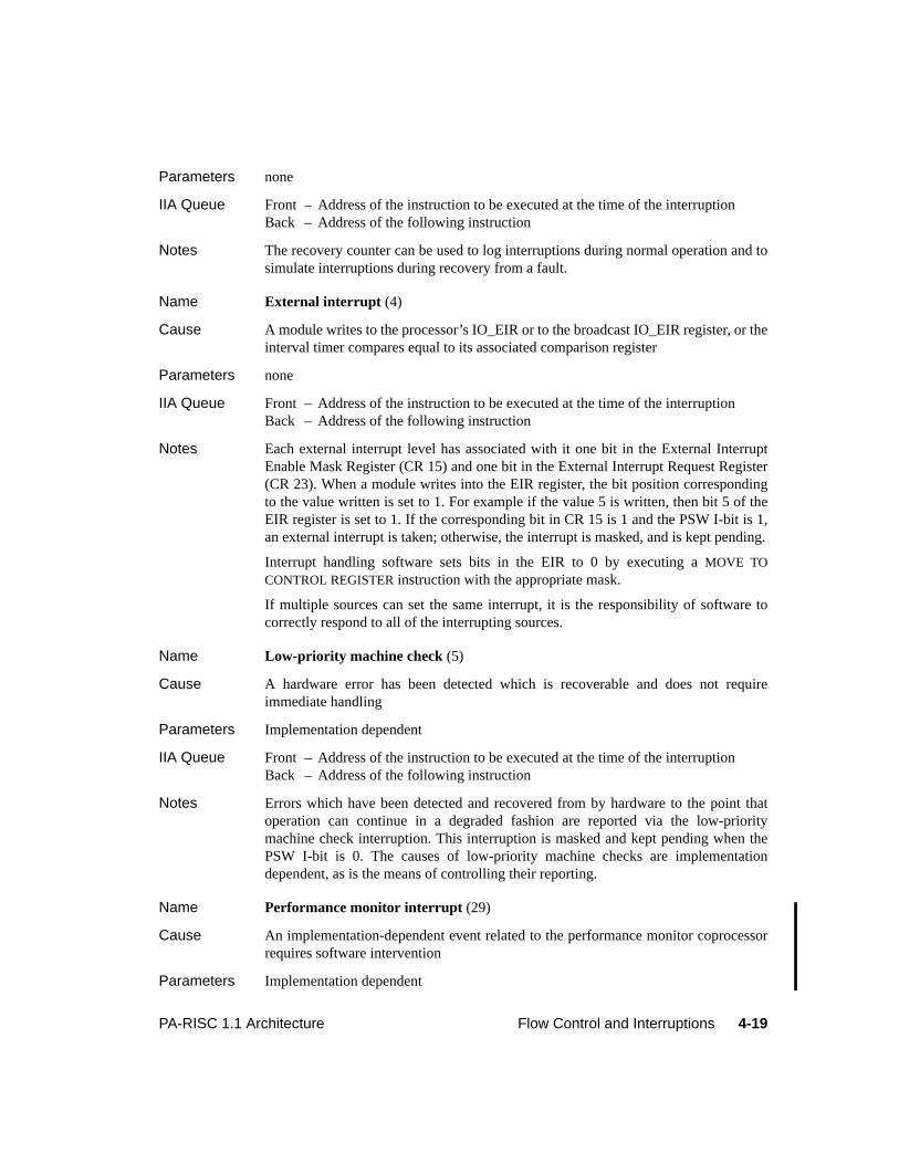
4-19PA-RISC 1.1 Architecture Flow Control and Interruptions
Parameters none
IIA Queue Front – Address of the instruction to be executed at the time of the interruptionBack – Address of the following instruction
Notes The recovery counter can be used to log interruptions during normal operation and tosimulate interruptions during recovery from a fault.
Name External interrupt (4)
Cause A module writes to the processor’s IO_EIR or to the broadcast IO_EIR register, or theinterval timer compares equal to its associated comparison register
Parameters none
IIA Queue Front – Address of the instruction to be executed at the time of the interruptionBack – Address of the following instruction
Notes Each external interrupt level has associated with it one bit in the External InterruptEnable Mask Register (CR 15) and one bit in the External Interrupt Request Register(CR 23). When a module writes into the EIR register, the bit position correspondingto the value written is set to 1. For example if the value 5 is written, then bit 5 of theEIR register is set to 1. If the corresponding bit in CR 15 is 1 and the PSW I-bit is 1,an external interrupt is taken; otherwise, the interrupt is masked, and is kept pending.
Interrupt handling software sets bits in the EIR to 0 by executing aMOVE TOCONTROL REGISTER instruction with the appropriate mask.
If multiple sources can set the same interrupt, it is the responsibility of software tocorrectly respond to all of the interrupting sources.
Name Low-priority machine check (5)
Cause A hardware error has been detected which is recoverable and does not requireimmediate handling
Parameters Implementation dependent
IIA Queue Front – Address of the instruction to be executed at the time of the interruptionBack – Address of the following instruction
Notes Errors which have been detected and recovered from by hardware to the point thatoperation can continue in a degraded fashion are reported via the low-prioritymachine check interruption. This interruption is masked and kept pending when thePSW I-bit is 0. The causes of low-priority machine checks are implementationdependent, as is the means of controlling their reporting.
Name Performance monitor interrupt (29)
Cause An implementation-dependent event related to the performance monitor coprocessorrequires software intervention
Parameters Implementation dependent
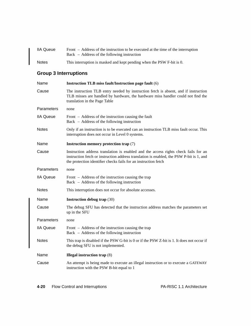
4-20 Flow Control and Interruptions PA-RISC 1.1 Architecture
IIA Queue Front – Address of the instruction to be executed at the time of the interruptionBack – Address of the following instruction
Notes This interruption is masked and kept pending when the PSW F-bit is 0.
Group 3 Interruptions
Name Instruction TLB miss fault/Instruction page fault (6)
Cause The instruction TLB entry needed by instruction fetch is absent, and if instructionTLB misses are handled by hardware, the hardware miss handler could not find thetranslation in the Page Table
Parameters none
IIA Queue Front – Address of the instruction causing the faultBack – Address of the following instruction
Notes Only if an instruction is to be executed can an instruction TLB miss fault occur. Thisinterruption does not occur in Level 0 systems.
Name Instruction memory protection trap (7)
Cause Instruction address translation is enabled and the access rights check fails for aninstruction fetch or instruction address translation is enabled, the PSW P-bit is 1, andthe protection identifier checks fails for an instruction fetch
Parameters none
IIA Queue Front – Address of the instruction causing the trapBack – Address of the following instruction
Notes This interruption does not occur for absolute accesses.
Name Instruction debug trap (30)
Cause The debug SFU has detected that the instruction address matches the parameters setup in the SFU
Parameters none
IIA Queue Front – Address of the instruction causing the trapBack – Address of the following instruction
Notes This trap is disabled if the PSW G-bit is 0 or if the PSW Z-bit is 1. It does not occur ifthe debug SFU is not implemented.
Name Illegal instruction trap (8)
Cause An attempt is being made to execute an illegal instruction or to execute aGATEWAYinstruction with the PSW B-bit equal to 1
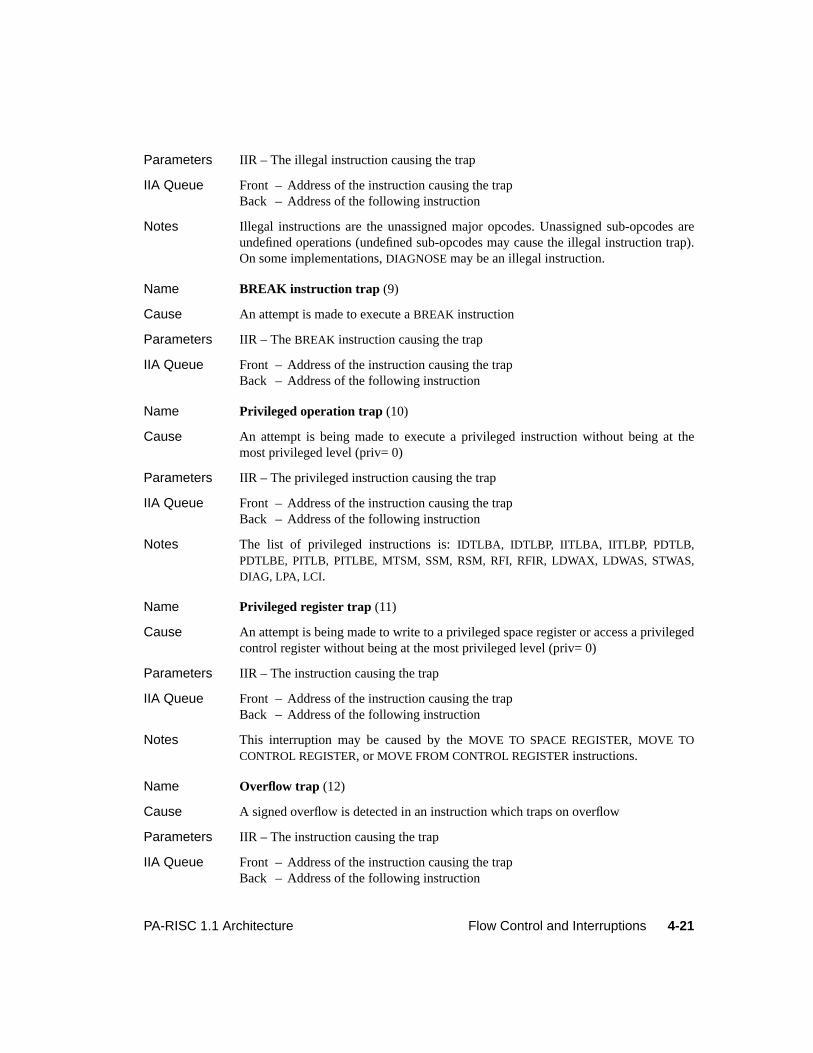
4-21PA-RISC 1.1 Architecture Flow Control and Interruptions
Parameters IIR – The illegal instruction causing the trap
IIA Queue Front – Address of the instruction causing the trapBack – Address of the following instruction
Notes Illegal instructions are the unassigned major opcodes. Unassigned sub-opcodes areundefined operations (undefined sub-opcodes may cause the illegal instruction trap).On some implementations,DIAGNOSE may be an illegal instruction.
Name BREAK instruction trap (9)
Cause An attempt is made to execute aBREAK instruction
Parameters IIR – TheBREAK instruction causing the trap
IIA Queue Front – Address of the instruction causing the trapBack – Address of the following instruction
Name Privileged operation trap (10)
Cause An attempt is being made to execute a privileged instruction without being at themost privileged level (priv= 0)
Parameters IIR – The privileged instruction causing the trap
IIA Queue Front – Address of the instruction causing the trapBack – Address of the following instruction
Notes The list of privileged instructions is:IDTLBA, IDTLBP, IITLBA, IITLBP, PDTLB,PDTLBE, PITLB, PITLBE, MTSM, SSM, RSM, RFI, RFIR, LDWAX, LDWAS, STWAS,DIAG, LPA, LCI.
Name Privileged register trap (11)
Cause An attempt is being made to write to a privileged space register or access a privilegedcontrol register without being at the most privileged level (priv= 0)
Parameters IIR – The instruction causing the trap
IIA Queue Front – Address of the instruction causing the trapBack – Address of the following instruction
Notes This interruption may be caused by theMOVE TO SPACE REGISTER, MOVE TOCONTROL REGISTER, or MOVE FROM CONTROL REGISTER instructions.
Name Overflow trap (12)
Cause A signed overflow is detected in an instruction which traps on overflow
Parameters IIR – The instruction causing the trap
IIA Queue Front – Address of the instruction causing the trapBack – Address of the following instruction
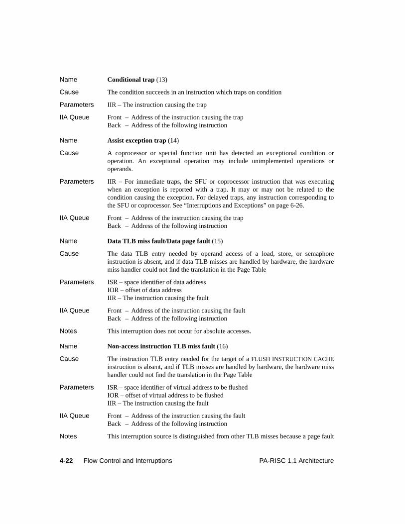
4-22 Flow Control and Interruptions PA-RISC 1.1 Architecture
Name Conditional trap (13)
Cause The condition succeeds in an instruction which traps on condition
Parameters IIR – The instruction causing the trap
IIA Queue Front – Address of the instruction causing the trapBack – Address of the following instruction
Name Assist exception trap (14)
Cause A coprocessor or special function unit has detected an exceptional condition oroperation. An exceptional operation may include unimplemented operations oroperands.
Parameters IIR – For immediate traps, the SFU or coprocessor instruction that was executingwhen an exception is reported with a trap. It may or may not be related to thecondition causing the exception. For delayed traps, any instruction corresponding tothe SFU or coprocessor. See “Interruptions and Exceptions” on page 6-26.
IIA Queue Front – Address of the instruction causing the trapBack – Address of the following instruction
Name Data TLB miss fault/Data page fault (15)
Cause The data TLB entry needed by operand access of a load, store, or semaphoreinstruction is absent, and if data TLB misses are handled by hardware, the hardwaremiss handler could not find the translation in the Page Table
Parameters ISR – space identifier of data addressIOR – offset of data addressIIR – The instruction causing the fault
IIA Queue Front – Address of the instruction causing the faultBack – Address of the following instruction
Notes This interruption does not occur for absolute accesses.
Name Non-access instruction TLB miss fault (16)
Cause The instruction TLB entry needed for the target of aFLUSH INSTRUCTION CACHEinstruction is absent, and if TLB misses are handled by hardware, the hardware misshandler could not find the translation in the Page Table
Parameters ISR – space identifier of virtual address to be flushedIOR – offset of virtual address to be flushedIIR – The instruction causing the fault
IIA Queue Front – Address of the instruction causing the faultBack – Address of the following instruction
Notes This interruption source is distinguished from other TLB misses because a page fault

4-23PA-RISC 1.1 Architecture Flow Control and Interruptions
should not result in reading the faulting page from disk. This interruption does notoccur for absolute accesses.
Name Non-access data TLB miss fault/Non-access data page fault (17)
Cause The data TLB entry needed by aLOAD PHYSICAL ADDRESS, PROBE READACCESS, PROBE READ ACCESS IMMEDIATE, PROBE WRITE ACCESS, PROBEWRITE ACCESS IMMEDIATE, FLUSH INSTRUCTION CACHE, PURGE DATA CACHE,or aFLUSH DATA CACHE instruction is not present, and if TLB misses are handled byhardware, the hardware miss handler could not find the translation in the Page Table
Parameters ISR – space identifier of virtual addressIOR – offset of virtual addressIIR – The instruction causing the fault
IIA Queue Front – Address of the instruction causing the faultBack – Address of the following instruction
Notes These interruption sources are distinguished from other TLB misses because a pagefault should not result in reading the faulting page from disk. This interruption doesnot occur for absolute accesses.
Name Data memory access rights trap (26)
Cause Data address translation is enabled, and an access rights check fails on an operandreference for a load, store, or semaphore instruction, or a cache purge operation
Parameters ISR – space identifier of the virtual addressIOR – offset of the virtual addressIIR – The instruction causing the trap
IIA Queue Front – Address of the instruction causing the trapBack – Address of the following instruction
Notes This interruption does not occur for absolute accesses.
Name Data memory protection ID trap (27)
Cause Data address translation is enabled, the PSW P-bit is 1, and a protection identifiercheck fails on an operand reference for a load, store, or semaphore instruction, orcache purge operation
Parameters ISR – space identifier of the virtual addressIOR – offset of the virtual addressIIR – The instruction causing the trap
IIA Queue Front – Address of the instruction causing the trapBack – Address of the following instruction
Notes This interruption does not occur for absolute accesses.
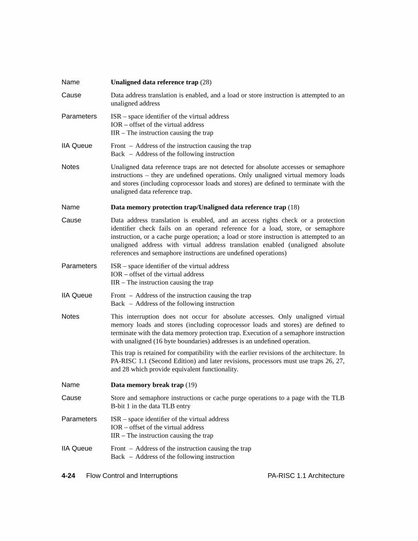
4-24 Flow Control and Interruptions PA-RISC 1.1 Architecture
Name Unaligned data reference trap (28)
Cause Data address translation is enabled, and a load or store instruction is attempted to anunaligned address
Parameters ISR – space identifier of the virtual addressIOR – offset of the virtual addressIIR – The instruction causing the trap
IIA Queue Front – Address of the instruction causing the trapBack – Address of the following instruction
Notes Unaligned data reference traps are not detected for absolute accesses or semaphoreinstructions – they are undefined operations. Only unaligned virtual memory loadsand stores (including coprocessor loads and stores) are defined to terminate with theunaligned data reference trap.
Name Data memory protection trap/Unaligned data reference trap (18)
Cause Data address translation is enabled, and an access rights check or a protectionidentifier check fails on an operand reference for a load, store, or semaphoreinstruction, or a cache purge operation; a load or store instruction is attempted to anunaligned address with virtual address translation enabled (unaligned absolutereferences and semaphore instructions are undefined operations)
Parameters ISR – space identifier of the virtual addressIOR – offset of the virtual addressIIR – The instruction causing the trap
IIA Queue Front – Address of the instruction causing the trapBack – Address of the following instruction
Notes This interruption does not occur for absolute accesses. Only unaligned virtualmemory loads and stores (including coprocessor loads and stores) are defined toterminate with the data memory protection trap. Execution of a semaphore instructionwith unaligned (16 byte boundaries) addresses is an undefined operation.
This trap is retained for compatibility with the earlier revisions of the architecture. InPA-RISC 1.1 (Second Edition) and later revisions, processors must use traps 26, 27,and 28 which provide equivalent functionality.
Name Data memory break trap (19)
Cause Store and semaphore instructions or cache purge operations to a page with the TLBB-bit 1 in the data TLB entry
Parameters ISR – space identifier of the virtual addressIOR – offset of the virtual addressIIR – The instruction causing the trap
IIA Queue Front – Address of the instruction causing the trapBack – Address of the following instruction
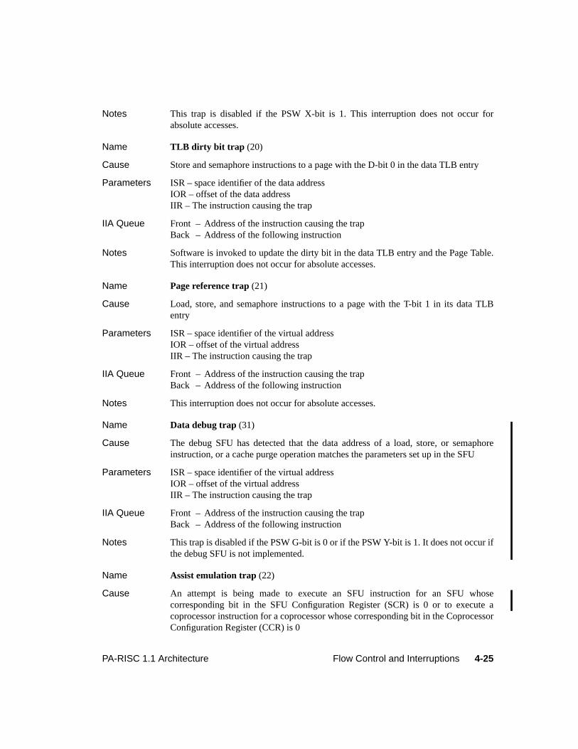
4-25PA-RISC 1.1 Architecture Flow Control and Interruptions
Notes This trap is disabled if the PSW X-bit is 1. This interruption does not occur forabsolute accesses.
Name TLB dirty bit trap (20)
Cause Store and semaphore instructions to a page with the D-bit 0 in the data TLB entry
Parameters ISR – space identifier of the data addressIOR – offset of the data addressIIR – The instruction causing the trap
IIA Queue Front – Address of the instruction causing the trapBack – Address of the following instruction
Notes Software is invoked to update the dirty bit in the data TLB entry and the Page Table.This interruption does not occur for absolute accesses.
Name Page reference trap (21)
Cause Load, store, and semaphore instructions to a page with the T-bit 1 in its data TLBentry
Parameters ISR – space identifier of the virtual addressIOR – offset of the virtual addressIIR – The instruction causing the trap
IIA Queue Front – Address of the instruction causing the trapBack – Address of the following instruction
Notes This interruption does not occur for absolute accesses.
Name Data debug trap (31)
Cause The debug SFU has detected that the data address of a load, store, or semaphoreinstruction, or a cache purge operation matches the parameters set up in the SFU
Parameters ISR – space identifier of the virtual addressIOR – offset of the virtual addressIIR – The instruction causing the trap
IIA Queue Front – Address of the instruction causing the trapBack – Address of the following instruction
Notes This trap is disabled if the PSW G-bit is 0 or if the PSW Y-bit is 1. It does not occur ifthe debug SFU is not implemented.
Name Assist emulation trap (22)
Cause An attempt is being made to execute an SFU instruction for an SFU whosecorresponding bit in the SFU Configuration Register (SCR) is 0 or to execute acoprocessor instruction for a coprocessor whose corresponding bit in the CoprocessorConfiguration Register (CCR) is 0
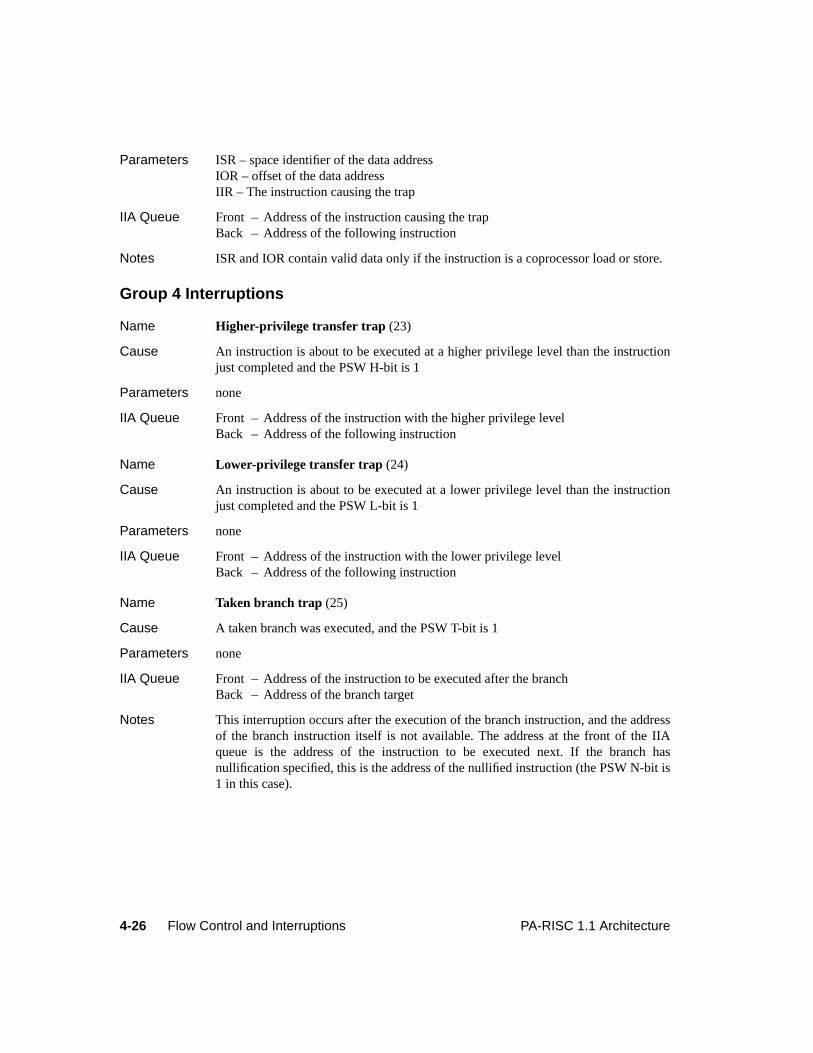
4-26 Flow Control and Interruptions PA-RISC 1.1 Architecture
Parameters ISR – space identifier of the data addressIOR – offset of the data addressIIR – The instruction causing the trap
IIA Queue Front – Address of the instruction causing the trapBack – Address of the following instruction
Notes ISR and IOR contain valid data only if the instruction is a coprocessor load or store.
Group 4 Interruptions
Name Higher-privilege transfer trap (23)
Cause An instruction is about to be executed at a higher privilege level than the instructionjust completed and the PSW H-bit is 1
Parameters none
IIA Queue Front – Address of the instruction with the higher privilege levelBack – Address of the following instruction
Name Lower-privilege transfer trap (24)
Cause An instruction is about to be executed at a lower privilege level than the instructionjust completed and the PSW L-bit is 1
Parameters none
IIA Queue Front – Address of the instruction with the lower privilege levelBack – Address of the following instruction
Name Taken branch trap (25)
Cause A taken branch was executed, and the PSW T-bit is 1
Parameters none
IIA Queue Front – Address of the instruction to be executed after the branchBack – Address of the branch target
Notes This interruption occurs after the execution of the branch instruction, and the addressof the branch instruction itself is not available. The address at the front of the IIAqueue is the address of the instruction to be executed next. If the branch hasnullification specified, this is the address of the nullified instruction (the PSW N-bit is1 in this case).
5-1PA-RISC 1.1 Architecture Instruction Set
5 Instruction Set
IntroductionThe PA-RISC instruction set consists of defined, undefined, illegal, and null instructions. This chapterdiscusses the concepts of undefined and null instructions and contains a detailed description of eachdefined instruction. Also included are descriptions of the conditions, their completers, and the notationused in the instruction descriptions.
The instruction descriptions are divided into the following functional groups:
1. Memory Reference instructions.
2. Branch instructions.
3. Long Immediate instructions.
4. Computation instructions.
5. System Control instructions.
6. Assist instructions.
Instructions are always 32 bits in width. A 6-bit major opcode is always the first field. Source registers,if specified, are often the next two 5-bit fields. Target registers, if specified, are not fixed in anyparticular 5-bit field. Depending on the major opcode, the remainder of the instruction word is dividedinto fields that specify immediate values, space registers, additional opcode extensions, conditions, andnullification.
Undefined and Illegal InstructionsNot all of the 64 possible major opcodes of the instruction set are defined as valid instructions. (SeeAppendix D, “Operation Codes”, for a list of the valid instruction opcodes.) An undefined major opcodeis considered anillegal instruction. Execution of an illegal instruction causes an illegal instruction trap.
Within each major opcode, there may be undefined opcode extensions and modifiers (these areundefined instructions). Interpretation of these opcodes is left to the implementor, but system integrityis not compromised. An undefined instruction, or sequence of undefined instructions, executed at agiven privilege level has no effect on system state other than what would have been produced by asequence of defined instructions running at the same privilege level. This limits the possible side-effectsthat could result from undefined instructions.
Undefined operations are equivalently specified. These result from normally defined instructions butwith operands or specifiers that are explicitly disallowed.
Executing an optional special operation or coprocessor instruction may cause an assist exception trap oran action that depends on the definition of the specific special function unit or coprocessor.
5-2 Instruction Set PA-RISC 1.1 Architecture
Reserved Instruction FieldsIn the Format section of the instruction pages, instruction fields markedrv are Reserved instructionfields. These fields are reserved for future architectural definition. To avoid incompatibility with futurerevisions of the architecture, software must provide zeros in all Reserved fields. When decodinginstructions, processors must ignore Reserved instruction fields.
Reserved Values of an Instruction FieldCertain values of some instruction fields are Reserved. These values are reserved for future architecturaldefinition. To avoid incompatibility with future revisions of the architecture, software must not use theReserved values. When decoding instructions, processors must treat the Reserved values as describedfor the specific field.
Null InstructionsNull instructions occur when unimplemented features of the architecture are accessed. The effect of anull instruction is identical to a nullified instruction except that the Recovery Counter is decremented.There is no effect on the machine state except that the IA queues are advanced and the PSW B-bit, N-bit, X-bit, Y-bit, and Z-bit are set to 0. Null instructions most commonly occur in Level 0 systems. Forexample, in a Level 0 system, the instruction that writes values into space registers is a null instruction.
Conditions and Control FlowMany instructions utilize conditions derived from the values of the operators and the operationperformed. The architecture defines three distinct sets of conditions that affect control flow:
1. Arithmetic/Logical Conditions.
2. Unit Conditions.
3. Shift/Extract/Deposit Conditions.
Every instruction that tests conditions uses one of these sets. Each set contains a maximum of eightseparate conditions and their negations. Most instructions that use conditions may also select thenegation of a condition. Exceptions are the instructions that use the extract/deposit conditions (shift,extract, deposit, and branch on bit instructions). The location of the bit specifying negation depends onthe instruction format. The conditional local branch instructions have the negation controlled by theopcode.
The condition completer field,cond, in the assembly language form of the instructions specifies acondition or the negation of a condition. This field expands in the machine language form to fill both the3-bit condition field,c, and the 1-bit negation field,f, as required.
Control flow is affected by checking the results of the operation performed by the current instruction.The ways that control flow can be affected are:
1. Branching – the result determines whether or not the branch is taken.
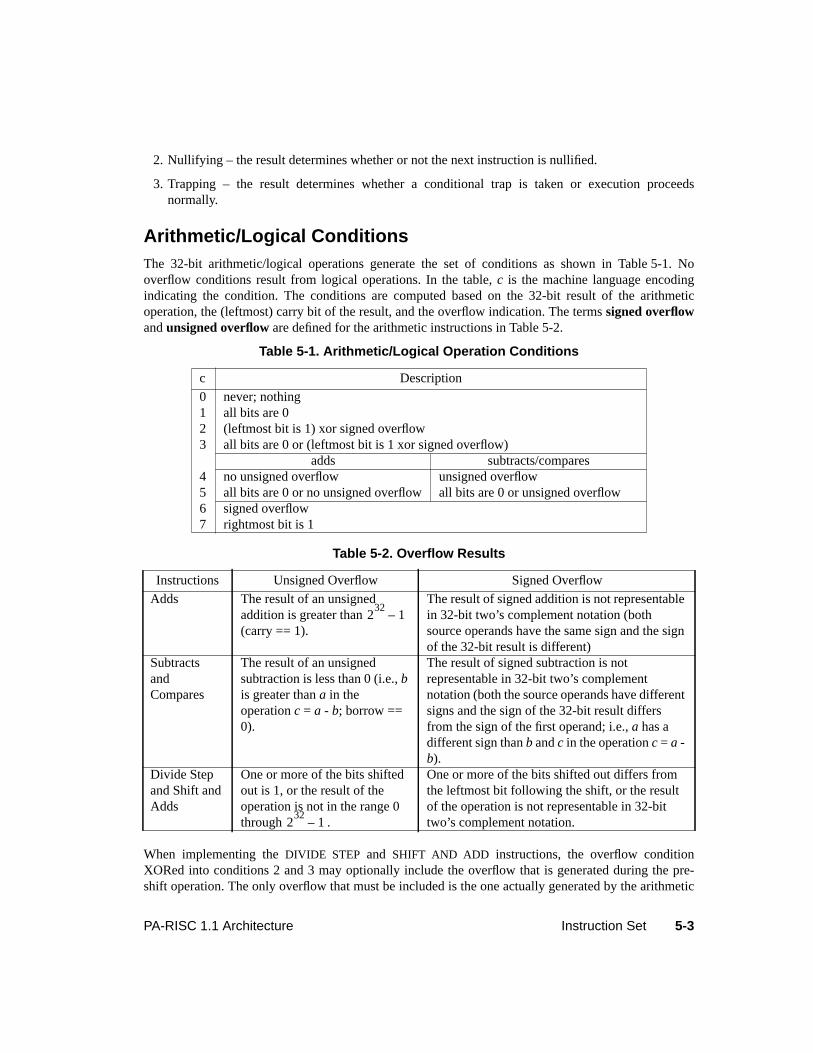
5-3PA-RISC 1.1 Architecture Instruction Set
2. Nullifying – the result determines whether or not the next instruction is nullified.
3. Trapping – the result determines whether a conditional trap is taken or execution proceedsnormally.
Arithmetic/Logical ConditionsThe 32-bit arithmetic/logical operations generate the set of conditions as shown in Table 5-1. Nooverflow conditions result from logical operations. In the table,c is the machine language encodingindicating the condition. The conditions are computed based on the 32-bit result of the arithmeticoperation, the (leftmost) carry bit of the result, and the overflow indication. The termssigned overflowandunsigned overflow are defined for the arithmetic instructions in Table 5-2.
When implementing theDIVIDE STEP and SHIFT AND ADD instructions, the overflow conditionXORed into conditions 2 and 3 may optionally include the overflow that is generated during the pre-shift operation. The only overflow that must be included is the one actually generated by the arithmetic
Table 5-1. Arithmetic/Logical Operation Conditions
c Description
0 never; nothing1 all bits are 02 (leftmost bit is 1) xor signed overflow3 all bits are 0 or (leftmost bit is 1 xor signed overflow)
adds subtracts/compares4 no unsigned overflow unsigned overflow5 all bits are 0 or no unsigned overflow all bits are 0 or unsigned overflow6 signed overflow7 rightmost bit is 1
Table 5-2. Overflow Results
Instructions Unsigned Overflow Signed Overflow
Adds The result of an unsignedaddition is greater than(carry == 1).
The result of signed addition is not representablein 32-bit two’s complement notation (bothsource operands have the same sign and the signof the 32-bit result is different)
SubtractsandCompares
The result of an unsignedsubtraction is less than 0 (i.e.,bis greater thana in theoperationc = a - b; borrow ==0).
The result of signed subtraction is notrepresentable in 32-bit two’s complementnotation (both the source operands have differentsigns and the sign of the 32-bit result differsfrom the sign of the first operand; i.e.,a has adifferent sign thanb andc in the operationc = a -b).
Divide Stepand Shift andAdds
One or more of the bits shiftedout is 1, or the result of theoperation is not in the range 0through .
One or more of the bits shifted out differs fromthe leftmost bit following the shift, or the resultof the operation is not representable in 32-bittwo’s complement notation.
232
1–
232
1–
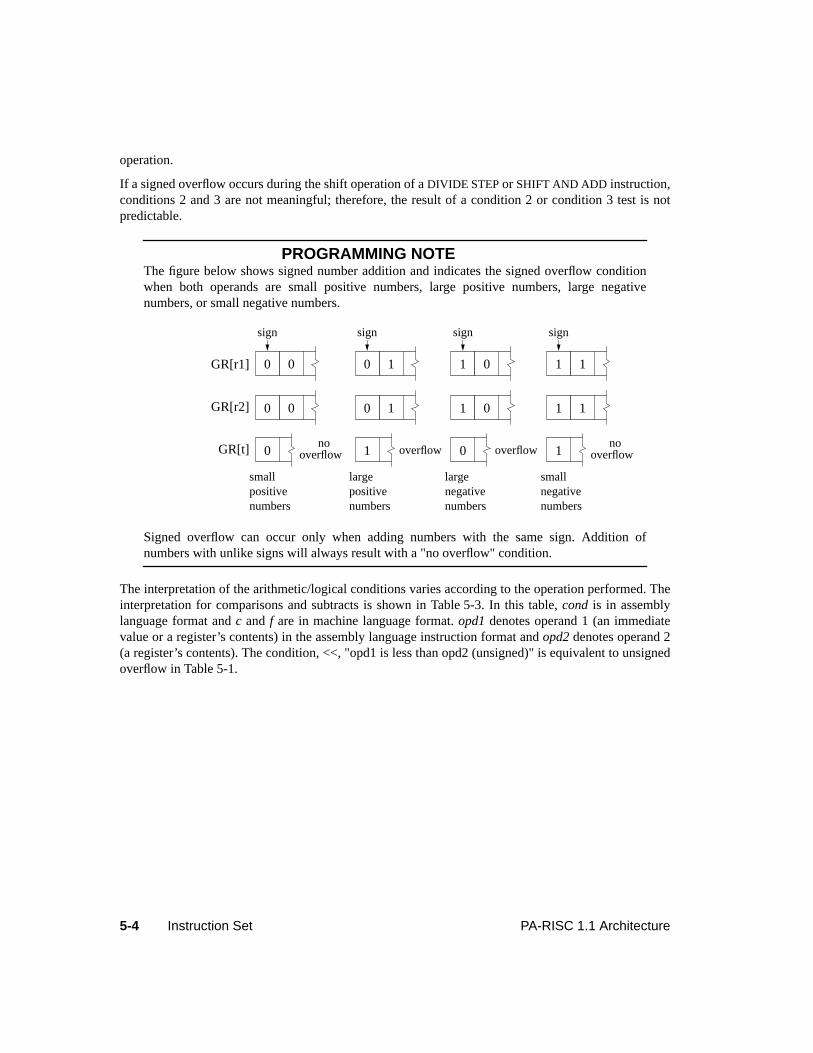
5-4 Instruction Set PA-RISC 1.1 Architecture
operation.
If a signed overflow occurs during the shift operation of aDIVIDE STEP or SHIFT AND ADD instruction,conditions 2 and 3 are not meaningful; therefore, the result of a condition 2 or condition 3 test is notpredictable.
PROGRAMMING NOTEThe figure below shows signed number addition and indicates the signed overflow conditionwhen both operands are small positive numbers, large positive numbers, large negativenumbers, or small negative numbers.
Signed overflow can occur only when adding numbers with the same sign. Addition ofnumbers with unlike signs will always result with a "no overflow" condition.
The interpretation of the arithmetic/logical conditions varies according to the operation performed. Theinterpretation for comparisons and subtracts is shown in Table 5-3. In this table,cond is in assemblylanguage format andc andf are in machine language format.opd1 denotes operand 1 (an immediatevalue or a register’s contents) in the assembly language instruction format andopd2 denotes operand 2(a register’s contents). The condition, <<, "opd1 is less than opd2 (unsigned)" is equivalent to unsignedoverflow in Table 5-1.
GR[r1]
GR[r2]
GR[t]
smallpositivenumbers
largepositivenumbers
largenegativenumbers
smallnegativenumbers
0 0
sign
0 1
sign
1 0
sign
1 1
sign
0 0 0 1 1 0 1 1
0no
overflow 1 overflow 0 overflow 1no
overflow
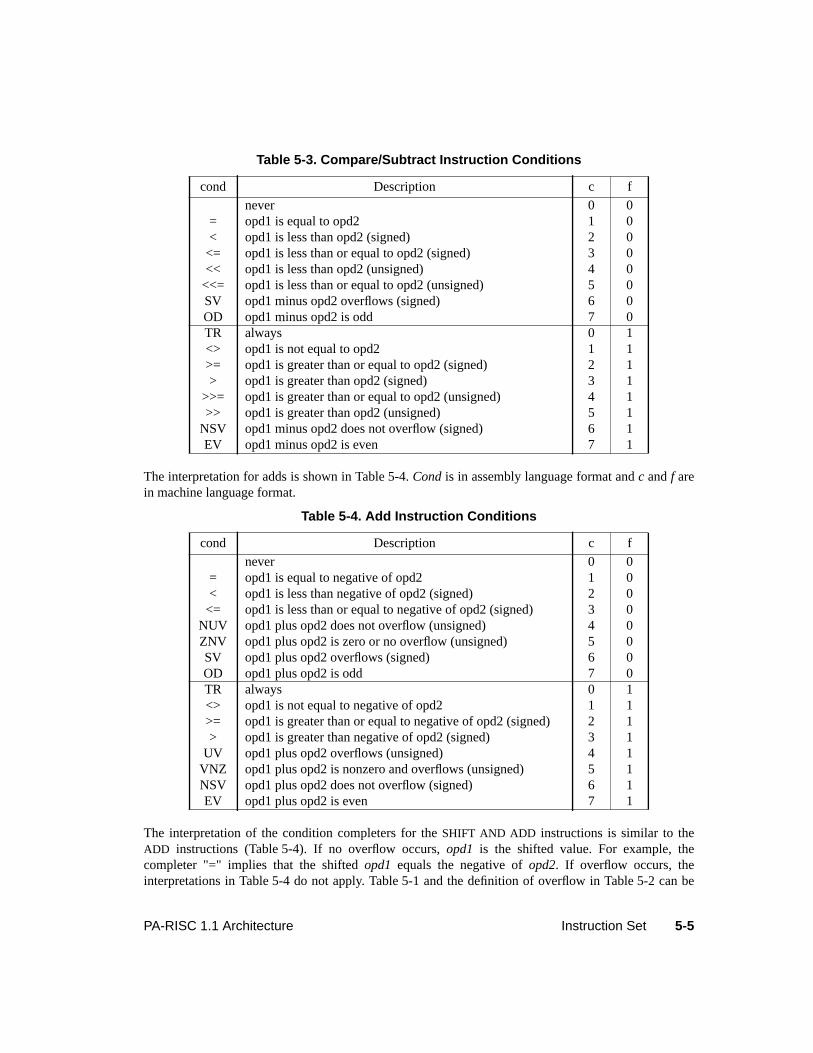
5-5PA-RISC 1.1 Architecture Instruction Set
The interpretation for adds is shown in Table 5-4.Cond is in assembly language format andc andf arein machine language format.
The interpretation of the condition completers for theSHIFT AND ADD instructions is similar to theADD instructions (Table 5-4). If no overflow occurs,opd1 is the shifted value. For example, thecompleter "=" implies that the shiftedopd1 equals the negative ofopd2. If overflow occurs, theinterpretations in Table 5-4 do not apply. Table 5-1 and the definition of overflow in Table 5-2 can be
Table 5-3. Compare/Subtract Instruction Conditions
cond Description c f
never 0 0= opd1 is equal to opd2 1 0< opd1 is less than opd2 (signed) 2 0
<= opd1 is less than or equal to opd2 (signed) 3 0<< opd1 is less than opd2 (unsigned) 4 0
<<= opd1 is less than or equal to opd2 (unsigned) 5 0SV opd1 minus opd2 overflows (signed) 6 0OD opd1 minus opd2 is odd 7 0TR always 0 1<> opd1 is not equal to opd2 1 1>= opd1 is greater than or equal to opd2 (signed) 2 1> opd1 is greater than opd2 (signed) 3 1
>>= opd1 is greater than or equal to opd2 (unsigned) 4 1>> opd1 is greater than opd2 (unsigned) 5 1
NSV opd1 minus opd2 does not overflow (signed) 6 1EV opd1 minus opd2 is even 7 1
Table 5-4. Add Instruction Conditions
cond Description c f
never 0 0= opd1 is equal to negative of opd2 1 0< opd1 is less than negative of opd2 (signed) 2 0
<= opd1 is less than or equal to negative of opd2 (signed) 3 0NUV opd1 plus opd2 does not overflow (unsigned) 4 0ZNV opd1 plus opd2 is zero or no overflow (unsigned) 5 0SV opd1 plus opd2 overflows (signed) 6 0OD opd1 plus opd2 is odd 7 0TR always 0 1<> opd1 is not equal to negative of opd2 1 1>= opd1 is greater than or equal to negative of opd2 (signed) 2 1> opd1 is greater than negative of opd2 (signed) 3 1
UV opd1 plus opd2 overflows (unsigned) 4 1VNZ opd1 plus opd2 is nonzero and overflows (unsigned) 5 1NSV opd1 plus opd2 does not overflow (signed) 6 1EV opd1 plus opd2 is even 7 1
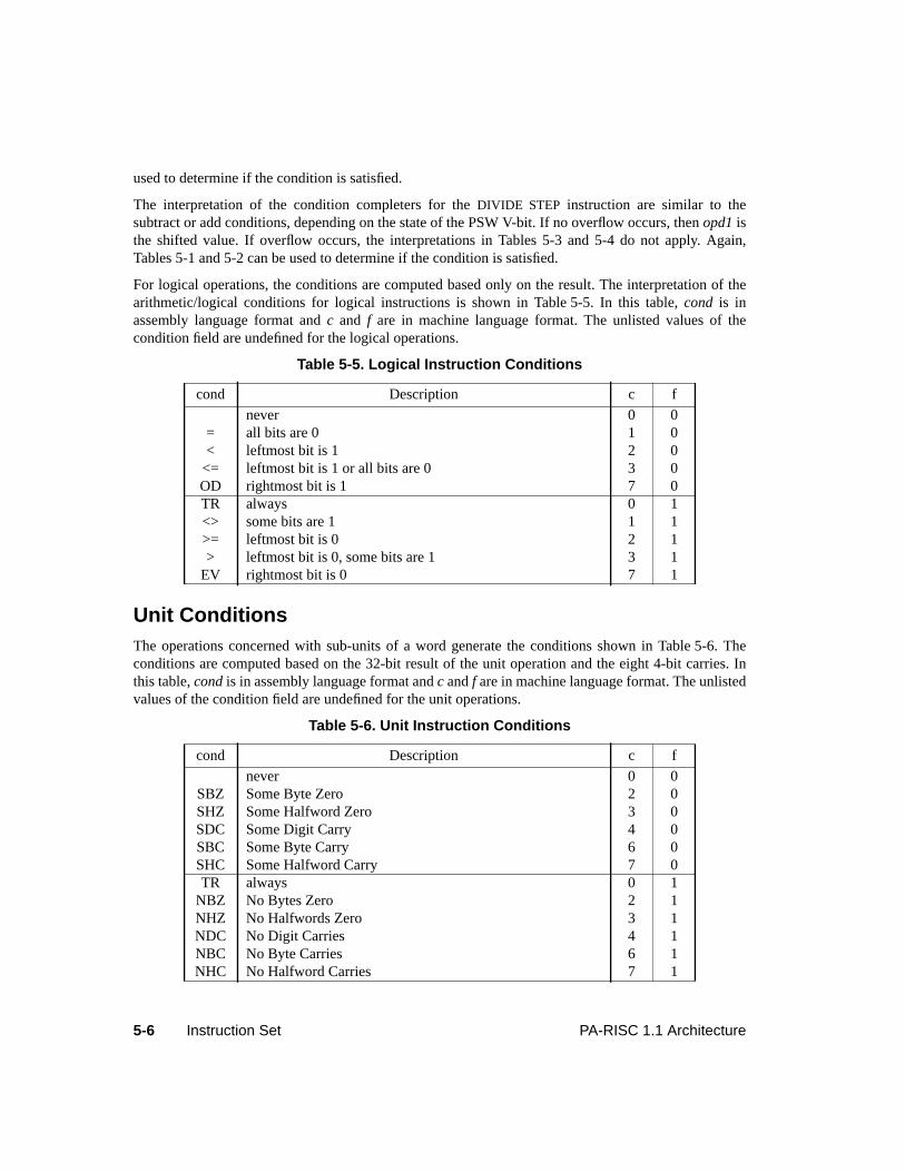
5-6 Instruction Set PA-RISC 1.1 Architecture
used to determine if the condition is satisfied.
The interpretation of the condition completers for theDIVIDE STEP instruction are similar to thesubtract or add conditions, depending on the state of the PSW V-bit. If no overflow occurs, thenopd1 isthe shifted value. If overflow occurs, the interpretations in Tables 5-3 and 5-4 do not apply. Again,Tables 5-1 and 5-2 can be used to determine if the condition is satisfied.
For logical operations, the conditions are computed based only on the result. The interpretation of thearithmetic/logical conditions for logical instructions is shown in Table 5-5. In this table,cond is inassembly language format andc and f are in machine language format. The unlisted values of thecondition field are undefined for the logical operations.
Unit ConditionsThe operations concerned with sub-units of a word generate the conditions shown in Table 5-6. Theconditions are computed based on the 32-bit result of the unit operation and the eight 4-bit carries. Inthis table,cond is in assembly language format andc andf are in machine language format. The unlistedvalues of the condition field are undefined for the unit operations.
Table 5-5. Logical Instruction Conditions
cond Description c f
never 0 0= all bits are 0 1 0< leftmost bit is 1 2 0
<= leftmost bit is 1 or all bits are 0 3 0OD rightmost bit is 1 7 0TR always 0 1<> some bits are 1 1 1>= leftmost bit is 0 2 1> leftmost bit is 0, some bits are 1 3 1
EV rightmost bit is 0 7 1
Table 5-6. Unit Instruction Conditions
cond Description c f
never 0 0SBZ Some Byte Zero 2 0SHZ Some Halfword Zero 3 0SDC Some Digit Carry 4 0SBC Some Byte Carry 6 0SHC Some Halfword Carry 7 0TR always 0 1
NBZ No Bytes Zero 2 1NHZ No Halfwords Zero 3 1NDC No Digit Carries 4 1NBC No Byte Carries 6 1NHC No Halfword Carries 7 1
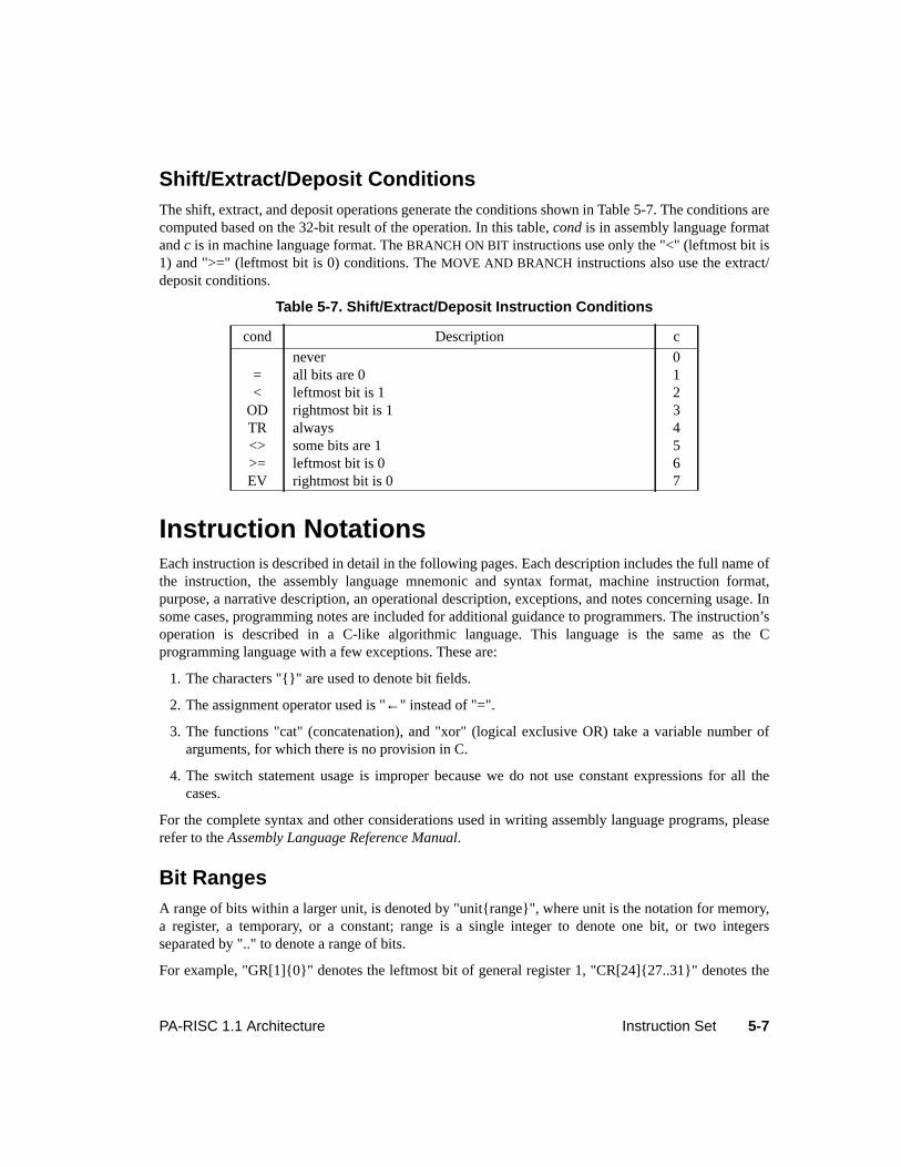
5-7PA-RISC 1.1 Architecture Instruction Set
Shift/Extract/Deposit ConditionsThe shift, extract, and deposit operations generate the conditions shown in Table 5-7. The conditions arecomputed based on the 32-bit result of the operation. In this table,cond is in assembly language formatandc is in machine language format. TheBRANCH ON BIT instructions use only the "<" (leftmost bit is1) and ">=" (leftmost bit is 0) conditions. TheMOVE AND BRANCH instructions also use the extract/deposit conditions.
Instruction NotationsEach instruction is described in detail in the following pages. Each description includes the full name ofthe instruction, the assembly language mnemonic and syntax format, machine instruction format,purpose, a narrative description, an operational description, exceptions, and notes concerning usage. Insome cases, programming notes are included for additional guidance to programmers. The instruction’soperation is described in a C-like algorithmic language. This language is the same as the Cprogramming language with a few exceptions. These are:
1. The characters "{}" are used to denote bit fields.
2. The assignment operator used is "←" instead of "=".
3. The functions "cat" (concatenation), and "xor" (logical exclusive OR) take a variable number ofarguments, for which there is no provision in C.
4. The switch statement usage is improper because we do not use constant expressions for all thecases.
For the complete syntax and other considerations used in writing assembly language programs, pleaserefer to theAssembly Language Reference Manual.
Bit RangesA range of bits within a larger unit, is denoted by "unit{range}", where unit is the notation for memory,a register, a temporary, or a constant; range is a single integer to denote one bit, or two integersseparated by ".." to denote a range of bits.
For example, "GR[1]{0}" denotes the leftmost bit of general register 1, "CR[24]{27..31}" denotes the
Table 5-7. Shift/Extract/Deposit Instruction Conditions
cond Description c
never 0= all bits are 0 1< leftmost bit is 1 2
OD rightmost bit is 1 3TR always 4<> some bits are 1 5>= leftmost bit is 0 6EV rightmost bit is 0 7
5-8 Instruction Set PA-RISC 1.1 Architecture
rightmost five bits of control register 24, and "5{0..6}" denotes a 7-bit field containing the number 5. Ifm > n, then {m..n} denotes the null range.
RegistersIn general, a register name consists of two or three uppercase letters. The name of a member of aregister array consists of a register name followed by an index in square brackets. For example, "GR[1]"denotes general register 1.
The named registers and register arrays used in the operational descriptions are:
The Processor Status Word and the Interruption Processor Status Word, denoted by "PSW" and "IPSW",are treated as a series of 1-bit and multiple-bit fields. A field of either is denoted by the register namefollowed by a field name in square brackets, and bit ranges within such fields are denoted by the usualnotation. For example, PSW[C/B] denotes the 8-bit carry/borrow field of the PSW and PSW[C/B]{0}denotes bit 0 of that field.
TemporariesA temporary name comprises three or more lowercase letters and denotes a quantity which requiresnaming, either for clarity, or because of limitations imposed by the sequentiality of the operationalnotation. It may or may not represent an actual processing resource in the hardware. The length of thequantity denoted by a temporary is implicitly determined and is equal to that of the quantity firstassigned to it in an operational description.
OperatorsThe operators used and their meanings are as follows:
All operators are binary, except that “∼” is unary and “–” is both binary and unary, depending on the
Register Range Description
GR[t] t = 0..31 General registersSHR[t] t = 0..6 Shadow registersSR[t] t = 0..7 Space registersCR[t] t = 0, 8..31 Control registersCPR[uid][t] t = 0..31 Coprocessor "uid" registersFPR[t] t = 0..31 Floating-point coprocessor registers
← assignment | bitwise or+ addition == equal to– subtraction < less than* multiplication > greater than~ bitwise complement != not equal to&& logical and <= less than or equal to& bitwise and >= greater than or equal to|| logical or
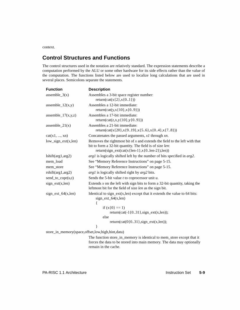
5-9PA-RISC 1.1 Architecture Instruction Set
context.
Control Structures and FunctionsThe control structures used in the notation are relatively standard. The expression statements describe acomputation performed by the ALU or some other hardware for its side effects rather than the value ofthe computation. The functions listed below are used to localize long calculations that are used inseveral places. Semicolons separate the statements.
Function Descriptionassemble_3(x) Assembles a 3-bit space register number:
return(cat(x{2},x{0..1}))
assemble_12(x,y) Assembles a 12-bit immediate:return(cat(y,x{10},x{0..9}))
assemble_17(x,y,z) Assembles a 17-bit immediate:return(cat(z,x,y{10},y{0..9}))
assemble_21(x) Assembles a 21-bit immediate:return(cat(x{20},x{9..19},x{5..6},x{0..4},x{7..8}))
cat(x1, ..., xn) Concatenates the passed arguments,x1 throughxn.
low_sign_ext(x,len) Removes the rightmost bit ofx and extends the field to the left with thatbit to form a 32-bit quantity. The field is of sizelen:
return(sign_ext(cat(x{len-1},x{0..len-2}),len))
lshift(arg1,arg2) arg1 is logically shifted left by the number of bits specified inarg2.
mem_load See “Memory Reference Instructions” on page 5-15.
mem_store See “Memory Reference Instructions” on page 5-15.
rshift(arg1,arg2) arg1 is logically shifted right byarg2 bits.
send_to_copr(u,t) Sends the 5-bit valuet to coprocessor unitu.
sign_ext(x,len) Extendsx on the left with sign bits to form a 32-bit quantity, taking theleftmost bit for the field of sizelen as the sign bit.
sign_ext_64(x,len) Identical to sign_ext(x,len) except that it extends the value to 64 bits:sign_ext_64(x,len){
if (x{0} == 1)return(cat(-1{0..31},sign_ext(x,len));
elsereturn(cat(0{0..31},sign_ext(x,len));
}
store_in_memory(space,offset,low,high,hint,data)
The function store_in_memory is identical to mem_store except that itforces the data to be stored into main memory. The data may optionallyremain in the cache.
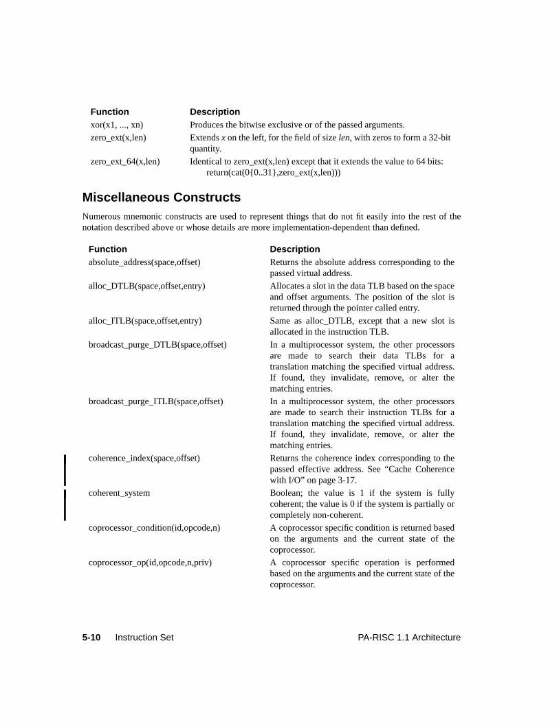
5-10 Instruction Set PA-RISC 1.1 Architecture
Miscellaneous ConstructsNumerous mnemonic constructs are used to represent things that do not fit easily into the rest of thenotation described above or whose details are more implementation-dependent than defined.
xor(x1, ..., xn) Produces the bitwise exclusive or of the passed arguments.
zero_ext(x,len) Extendsx on the left, for the field of sizelen, with zeros to form a 32-bitquantity.
zero_ext_64(x,len) Identical to zero_ext(x,len) except that it extends the value to 64 bits:return(cat(0{0..31},zero_ext(x,len)))
Function Descriptionabsolute_address(space,offset) Returns the absolute address corresponding to the
passed virtual address.
alloc_DTLB(space,offset,entry) Allocates a slot in the data TLB based on the spaceand offset arguments. The position of the slot isreturned through the pointer called entry.
alloc_ITLB(space,offset,entry) Same as alloc_DTLB, except that a new slot isallocated in the instruction TLB.
broadcast_purge_DTLB(space,offset) In a multiprocessor system, the other processorsare made to search their data TLBs for atranslation matching the specified virtual address.If found, they invalidate, remove, or alter thematching entries.
broadcast_purge_ITLB(space,offset) In a multiprocessor system, the other processorsare made to search their instruction TLBs for atranslation matching the specified virtual address.If found, they invalidate, remove, or alter thematching entries.
coherence_index(space,offset) Returns the coherence index corresponding to thepassed effective address. See “Cache Coherencewith I/O” on page 3-17.
coherent_system Boolean; the value is 1 if the system is fullycoherent; the value is 0 if the system is partially orcompletely non-coherent.
coprocessor_condition(id,opcode,n) A coprocessor specific condition is returned basedon the arguments and the current state of thecoprocessor.
coprocessor_op(id,opcode,n,priv) A coprocessor specific operation is performedbased on the arguments and the current state of thecoprocessor.
Function Description
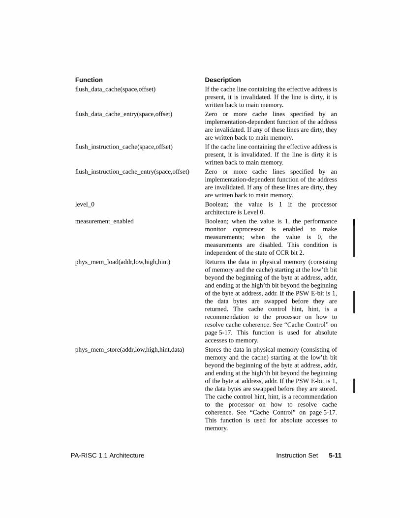
5-11PA-RISC 1.1 Architecture Instruction Set
flush_data_cache(space,offset) If the cache line containing the effective address ispresent, it is invalidated. If the line is dirty, it iswritten back to main memory.
flush_data_cache_entry(space,offset) Zero or more cache lines specified by animplementation-dependent function of the addressare invalidated. If any of these lines are dirty, theyare written back to main memory.
flush_instruction_cache(space,offset) If the cache line containing the effective address ispresent, it is invalidated. If the line is dirty it iswritten back to main memory.
flush_instruction_cache_entry(space,offset) Zero or more cache lines specified by animplementation-dependent function of the addressare invalidated. If any of these lines are dirty, theyare written back to main memory.
level_0 Boolean; the value is 1 if the processorarchitecture is Level 0.
measurement_enabled Boolean; when the value is 1, the performancemonitor coprocessor is enabled to makemeasurements; when the value is 0, themeasurements are disabled. This condition isindependent of the state of CCR bit 2.
phys_mem_load(addr,low,high,hint) Returns the data in physical memory (consistingof memory and the cache) starting at the low’th bitbeyond the beginning of the byte at address, addr,and ending at the high’th bit beyond the beginningof the byte at address, addr. If the PSW E-bit is 1,the data bytes are swapped before they arereturned. The cache control hint, hint, is arecommendation to the processor on how toresolve cache coherence. See “Cache Control” onpage 5-17. This function is used for absoluteaccesses to memory.
phys_mem_store(addr,low,high,hint,data) Stores the data in physical memory (consisting ofmemory and the cache) starting at the low’th bitbeyond the beginning of the byte at address, addr,and ending at the high’th bit beyond the beginningof the byte at address, addr. If the PSW E-bit is 1,the data bytes are swapped before they are stored.The cache control hint, hint, is a recommendationto the processor on how to resolve cachecoherence. See “Cache Control” on page 5-17.This function is used for absolute accesses tomemory.
Function Description
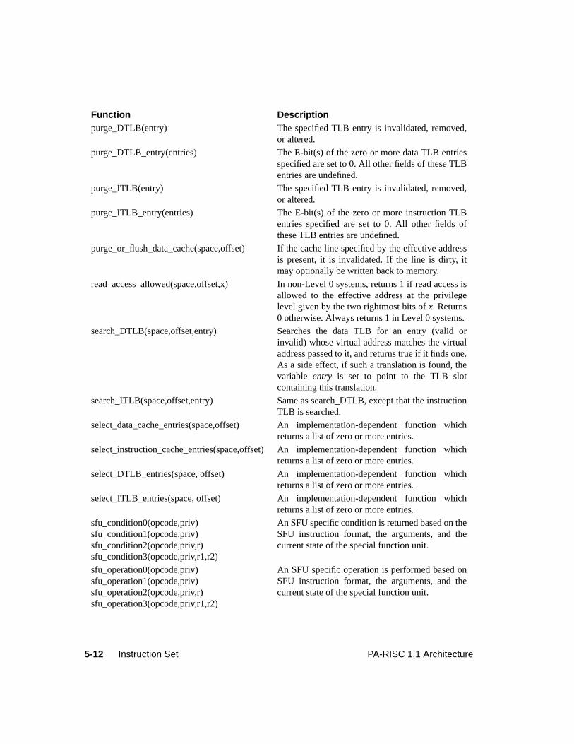
5-12 Instruction Set PA-RISC 1.1 Architecture
purge_DTLB(entry) The specified TLB entry is invalidated, removed,or altered.
purge_DTLB_entry(entries) The E-bit(s) of the zero or more data TLB entriesspecified are set to 0. All other fields of these TLBentries are undefined.
purge_ITLB(entry) The specified TLB entry is invalidated, removed,or altered.
purge_ITLB_entry(entries) The E-bit(s) of the zero or more instruction TLBentries specified are set to 0. All other fields ofthese TLB entries are undefined.
purge_or_flush_data_cache(space,offset) If the cache line specified by the effective addressis present, it is invalidated. If the line is dirty, itmay optionally be written back to memory.
read_access_allowed(space,offset,x) In non-Level 0 systems, returns 1 if read access isallowed to the effective address at the privilegelevel given by the two rightmost bits ofx. Returns0 otherwise. Always returns 1 in Level 0 systems.
search_DTLB(space,offset,entry) Searches the data TLB for an entry (valid orinvalid) whose virtual address matches the virtualaddress passed to it, and returns true if it finds one.As a side effect, if such a translation is found, thevariable entry is set to point to the TLB slotcontaining this translation.
search_ITLB(space,offset,entry) Same as search_DTLB, except that the instructionTLB is searched.
select_data_cache_entries(space,offset) An implementation-dependent function whichreturns a list of zero or more entries.
select_instruction_cache_entries(space,offset) An implementation-dependent function whichreturns a list of zero or more entries.
select_DTLB_entries(space, offset) An implementation-dependent function whichreturns a list of zero or more entries.
select_ITLB_entries(space, offset) An implementation-dependent function whichreturns a list of zero or more entries.
sfu_condition0(opcode,priv)sfu_condition1(opcode,priv)sfu_condition2(opcode,priv,r)sfu_condition3(opcode,priv,r1,r2)
An SFU specific condition is returned based on theSFU instruction format, the arguments, and thecurrent state of the special function unit.
sfu_operation0(opcode,priv)sfu_operation1(opcode,priv)sfu_operation2(opcode,priv,r)sfu_operation3(opcode,priv,r1,r2)
An SFU specific operation is performed based onSFU instruction format, the arguments, and thecurrent state of the special function unit.
Function Description
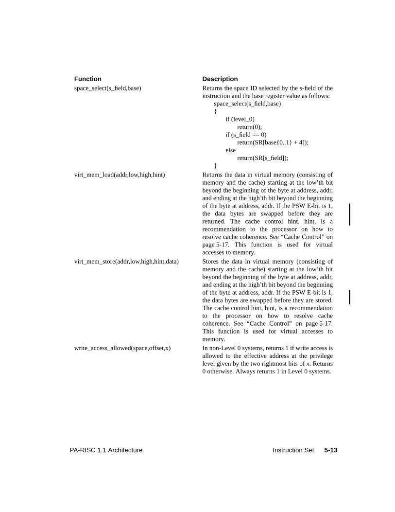
5-13PA-RISC 1.1 Architecture Instruction Set
space_select(s_field,base) Returns the space ID selected by the s-field of theinstruction and the base register value as follows:
space_select(s_field,base){
if (level_0)return(0);
if (s_field == 0)return(SR[base{0..1} + 4]);
elsereturn(SR[s_field]);
}
virt_mem_load(addr,low,high,hint) Returns the data in virtual memory (consisting ofmemory and the cache) starting at the low’th bitbeyond the beginning of the byte at address, addr,and ending at the high’th bit beyond the beginningof the byte at address, addr. If the PSW E-bit is 1,the data bytes are swapped before they arereturned. The cache control hint, hint, is arecommendation to the processor on how toresolve cache coherence. See “Cache Control” onpage 5-17. This function is used for virtualaccesses to memory.
virt_mem_store(addr,low,high,hint,data) Stores the data in virtual memory (consisting ofmemory and the cache) starting at the low’th bitbeyond the beginning of the byte at address, addr,and ending at the high’th bit beyond the beginningof the byte at address, addr. If the PSW E-bit is 1,the data bytes are swapped before they are stored.The cache control hint, hint, is a recommendationto the processor on how to resolve cachecoherence. See “Cache Control” on page 5-17.This function is used for virtual accesses tomemory.
write_access_allowed(space,offset,x) In non-Level 0 systems, returns 1 if write access isallowed to the effective address at the privilegelevel given by the two rightmost bits ofx. Returns0 otherwise. Always returns 1 in Level 0 systems.
Function Description
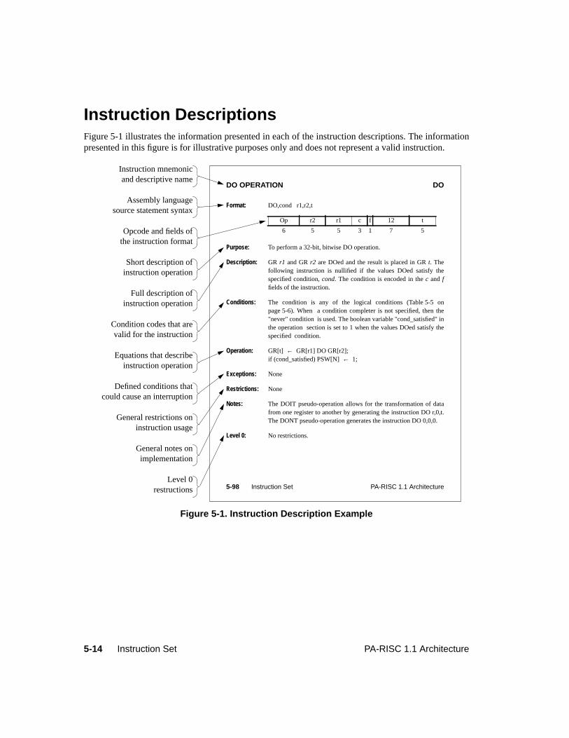
5-14 Instruction Set PA-RISC 1.1 Architecture
Instruction DescriptionsFigure 5-1 illustrates the information presented in each of the instruction descriptions. The informationpresented in this figure is for illustrative purposes only and does not represent a valid instruction.
Figure 5-1. Instruction Description Example
DO OPERATION DO
Format: DO,cond r1,r2,t
Purpose: To perform a 32-bit, bitwise DO operation.
Description: GR r1 and GRr2 are DOed and the result is placed in GRt. Thefollowing instruction is nullified if the values DOed satisfy thespecified condition,cond. The condition is encoded in thec and ffields of the instruction.
Conditions: The condition is any of the logical conditions (Table 5-5 onpage 5-6). When a condition completer is not specified, then the"never" condition is used. The boolean variable "cond_satisfied" inthe operation section is set to 1 when the values DOed satisfy thespecified condition.
Operation: GR[t] ← GR[r1] DO GR[r2];if (cond_satisfied) PSW[N]← 1;
Exceptions: None
Restrictions: None
Notes: The DOIT pseudo-operation allows for the transformation of datafrom one register to another by generating the instruction DO r,0,t.The DONT pseudo-operation generates the instruction DO 0,0,0.
Level 0: No restrictions.
Op r2 r1 c f 12 t
6 5 5 3 1 7 5
Instruction mnemonic and descriptive name
Assembly languagesource statement syntax
Opcode and fields ofthe instruction format
Short description ofinstruction operation
Full description ofinstruction operation
Equations that describeinstruction operation
Defined conditions thatcould cause an interruption
General restrictions oninstruction usage
General notes onimplementation
Level 0restructions
Condition codes that arevalid for the instruction
5-98 Instruction Set PA-RISC 1.1 Architecture
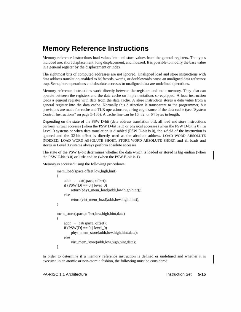
5-15PA-RISC 1.1 Architecture Instruction Set
5Instruction Set
Memory Reference InstructionsMemory reference instructions load values into and store values from the general registers. The typesincluded are: short displacement, long displacement, and indexed. It is possible to modify the base valuein a general register by the displacement or index.
The rightmost bits of computed addresses are not ignored. Unaligned load and store instructions withdata address translation enabled to halfwords, words, or doublewords cause an unaligned data referencetrap. Semaphore operations and absolute accesses to unaligned data are undefined operations.
Memory reference instructions work directly between the registers and main memory. They also canoperate between the registers and the data cache on implementations so equipped. A load instructionloads a general register with data from the data cache. A store instruction stores a data value from ageneral register into the data cache. Normally this distinction is transparent to the programmer, butprovisions are made for cache and TLB operations requiring cognizance of the data cache (see “SystemControl Instructions” on page 5-136). A cache line can be 16, 32, or 64 bytes in length.
Depending on the state of the PSW D-bit (data address translation bit), all load and store instructionsperform virtual accesses (when the PSW D-bit is 1) or physical accesses (when the PSW D-bit is 0). InLevel 0 systems or when data translation is disabled (PSW D-bit is 0), the s-field of the instruction isignored and the 32-bit offset is directly used as the absolute address.LOAD WORD ABSOLUTEINDEXED, LOAD WORD ABSOLUTE SHORT, STORE WORD ABSOLUTE SHORT, and all loads andstores in Level 0 systems always perform absolute accesses.
The state of the PSW E-bit determines whether the data which is loaded or stored is big endian (whenthe PSW E-bit is 0) or little endian (when the PSW E-bit is 1).
Memory is accessed using the following procedures:
mem_load(space,offset,low,high,hint){
addr ← cat(space, offset);if (PSW[D] == 0 || level_0)
return(phys_mem_load(addr,low,high,hint));else
return(virt_mem_load(addr,low,high,hint));}
mem_store(space,offset,low,high,hint,data){
addr ← cat(space, offset);if (PSW[D] == 0 || level_0)
phys_mem_store(addr,low,high,hint,data);else
virt_mem_store(addr,low,high,hint,data);}
In order to determine if a memory reference instruction is defined or undefined and whether it isexecuted in an atomic or non-atomic fashion, the following must be considered:
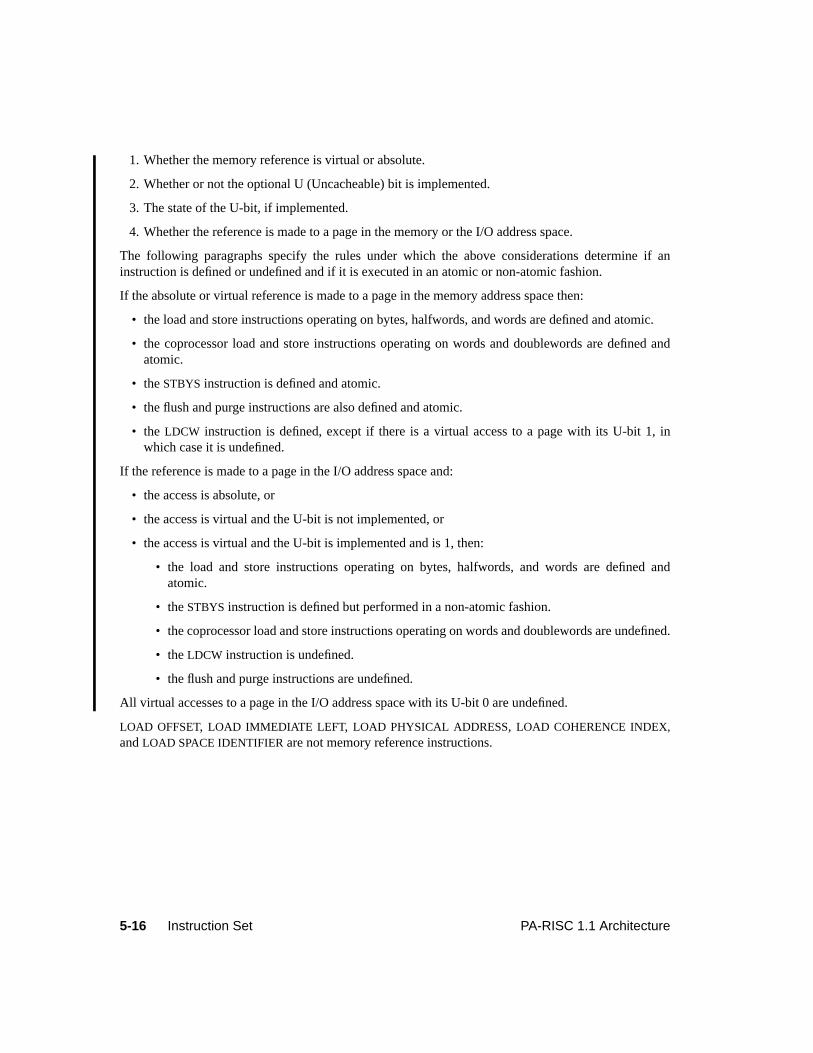
5-16 Instruction Set PA-RISC 1.1 Architecture
1. Whether the memory reference is virtual or absolute.
2. Whether or not the optional U (Uncacheable) bit is implemented.
3. The state of the U-bit, if implemented.
4. Whether the reference is made to a page in the memory or the I/O address space.
The following paragraphs specify the rules under which the above considerations determine if aninstruction is defined or undefined and if it is executed in an atomic or non-atomic fashion.
If the absolute or virtual reference is made to a page in the memory address space then:
• the load and store instructions operating on bytes, halfwords, and words are defined and atomic.
• the coprocessor load and store instructions operating on words and doublewords are defined andatomic.
• theSTBYS instruction is defined and atomic.
• the flush and purge instructions are also defined and atomic.
• the LDCW instruction is defined, except if there is a virtual access to a page with its U-bit 1, inwhich case it is undefined.
If the reference is made to a page in the I/O address space and:
• the access is absolute, or
• the access is virtual and the U-bit is not implemented, or
• the access is virtual and the U-bit is implemented and is 1, then:
• the load and store instructions operating on bytes, halfwords, and words are defined andatomic.
• theSTBYS instruction is defined but performed in a non-atomic fashion.
• the coprocessor load and store instructions operating on words and doublewords are undefined.
• theLDCW instruction is undefined.
• the flush and purge instructions are undefined.
All virtual accesses to a page in the I/O address space with its U-bit 0 are undefined.
LOAD OFFSET, LOAD IMMEDIATE LEFT, LOAD PHYSICAL ADDRESS, LOAD COHERENCE INDEX,andLOAD SPACE IDENTIFIER are not memory reference instructions.
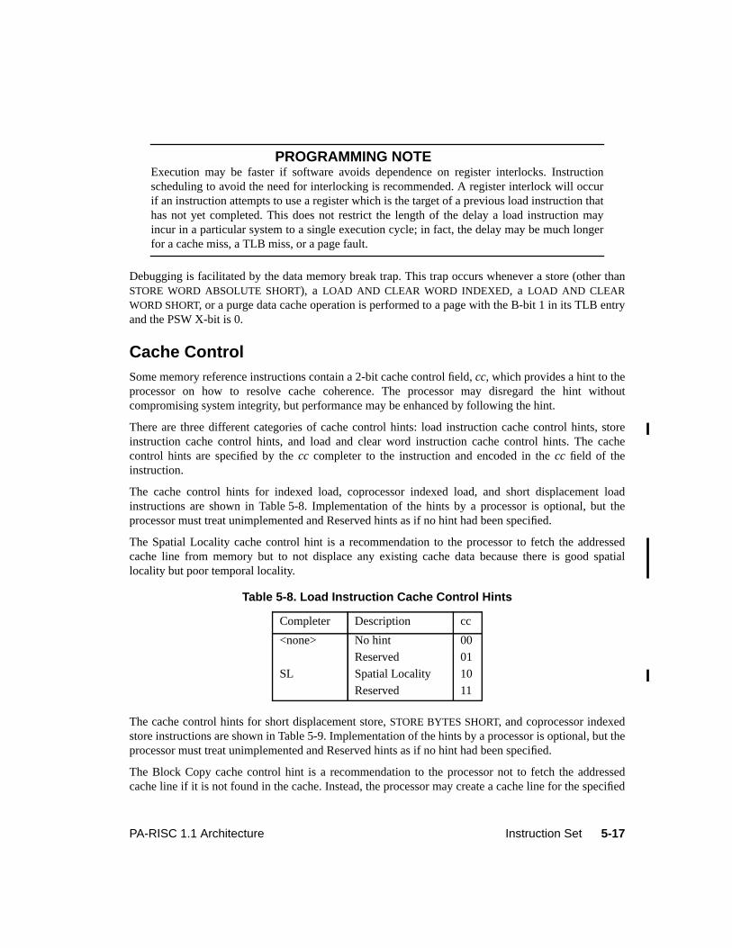
5-17PA-RISC 1.1 Architecture Instruction Set
PROGRAMMING NOTEExecution may be faster if software avoids dependence on register interlocks. Instructionscheduling to avoid the need for interlocking is recommended. A register interlock will occurif an instruction attempts to use a register which is the target of a previous load instruction thathas not yet completed. This does not restrict the length of the delay a load instruction mayincur in a particular system to a single execution cycle; in fact, the delay may be much longerfor a cache miss, a TLB miss, or a page fault.
Debugging is facilitated by the data memory break trap. This trap occurs whenever a store (other thanSTORE WORD ABSOLUTE SHORT), a LOAD AND CLEAR WORD INDEXED, a LOAD AND CLEARWORD SHORT, or a purge data cache operation is performed to a page with the B-bit 1 in its TLB entryand the PSW X-bit is 0.
Cache ControlSome memory reference instructions contain a 2-bit cache control field,cc, which provides a hint to theprocessor on how to resolve cache coherence. The processor may disregard the hint withoutcompromising system integrity, but performance may be enhanced by following the hint.
There are three different categories of cache control hints: load instruction cache control hints, storeinstruction cache control hints, and load and clear word instruction cache control hints. The cachecontrol hints are specified by thecc completer to the instruction and encoded in thecc field of theinstruction.
The cache control hints for indexed load, coprocessor indexed load, and short displacement loadinstructions are shown in Table 5-8. Implementation of the hints by a processor is optional, but theprocessor must treat unimplemented and Reserved hints as if no hint had been specified.
The Spatial Locality cache control hint is a recommendation to the processor to fetch the addressedcache line from memory but to not displace any existing cache data because there is good spatiallocality but poor temporal locality.
The cache control hints for short displacement store,STORE BYTES SHORT, and coprocessor indexedstore instructions are shown in Table 5-9. Implementation of the hints by a processor is optional, but theprocessor must treat unimplemented and Reserved hints as if no hint had been specified.
The Block Copy cache control hint is a recommendation to the processor not to fetch the addressedcache line if it is not found in the cache. Instead, the processor may create a cache line for the specified
Table 5-8. Load Instruction Cache Control Hints
Completer Description cc
<none> No hint 00
Reserved 01
SL Spatial Locality 10
Reserved 11
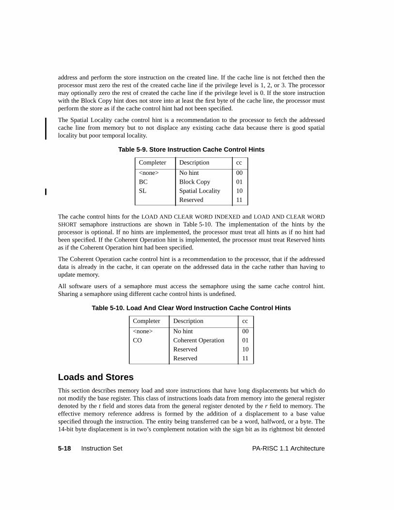
5-18 Instruction Set PA-RISC 1.1 Architecture
address and perform the store instruction on the created line. If the cache line is not fetched then theprocessor must zero the rest of the created cache line if the privilege level is 1, 2, or 3. The processormay optionally zero the rest of created the cache line if the privilege level is 0. If the store instructionwith the Block Copy hint does not store into at least the first byte of the cache line, the processor mustperform the store as if the cache control hint had not been specified.
The Spatial Locality cache control hint is a recommendation to the processor to fetch the addressedcache line from memory but to not displace any existing cache data because there is good spatiallocality but poor temporal locality.
The cache control hints for theLOAD AND CLEAR WORD INDEXED andLOAD AND CLEAR WORDSHORT semaphore instructions are shown in Table 5-10. The implementation of the hints by theprocessor is optional. If no hints are implemented, the processor must treat all hints as if no hint hadbeen specified. If the Coherent Operation hint is implemented, the processor must treat Reserved hintsas if the Coherent Operation hint had been specified.
The Coherent Operation cache control hint is a recommendation to the processor, that if the addresseddata is already in the cache, it can operate on the addressed data in the cache rather than having toupdate memory.
All software users of a semaphore must access the semaphore using the same cache control hint.Sharing a semaphore using different cache control hints is undefined.
Loads and StoresThis section describes memory load and store instructions that have long displacements but which donot modify the base register. This class of instructions loads data from memory into the general registerdenoted by thet field and stores data from the general register denoted by ther field to memory. Theeffective memory reference address is formed by the addition of a displacement to a base valuespecified through the instruction. The entity being transferred can be a word, halfword, or a byte. The14-bit byte displacement is in two’s complement notation with the sign bit as its rightmost bit denoted
Table 5-9. Store Instruction Cache Control Hints
Completer Description cc
<none> No hint 00
BC Block Copy 01
SL Spatial Locality 10
Reserved 11
Table 5-10. Load And Clear Word Instruction Cache Control Hints
Completer Description cc
<none> No hint 00
CO Coherent Operation 01
Reserved 10
Reserved 11
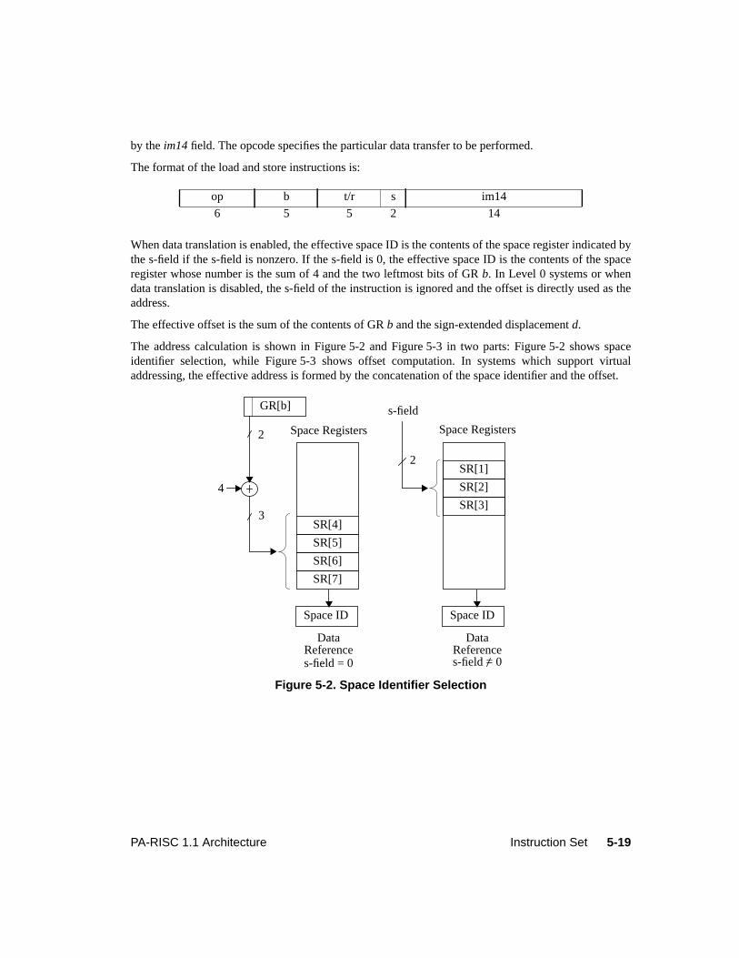
5-19PA-RISC 1.1 Architecture Instruction Set
by theim14 field. The opcode specifies the particular data transfer to be performed.
The format of the load and store instructions is:
When data translation is enabled, the effective space ID is the contents of the space register indicated bythe s-field if the s-field is nonzero. If the s-field is 0, the effective space ID is the contents of the spaceregister whose number is the sum of 4 and the two leftmost bits of GRb. In Level 0 systems or whendata translation is disabled, the s-field of the instruction is ignored and the offset is directly used as theaddress.
The effective offset is the sum of the contents of GRb and the sign-extended displacementd.
The address calculation is shown in Figure 5-2 and Figure 5-3 in two parts: Figure 5-2 shows spaceidentifier selection, while Figure 5-3 shows offset computation. In systems which support virtualaddressing, the effective address is formed by the concatenation of the space identifier and the offset.
op b t/r s im14
6 5 5 2 14
Figure 5-2. Space Identifier Selection
GR[b]
Space Registers
DataReference
s-field
s-field = 0
2
Space Registers
DataReferences-field = 0
2
3
4
SR[4]
SR[5]
SR[6]
SR[7]
SR[1]
SR[2]
SR[3]
Space ID Space ID
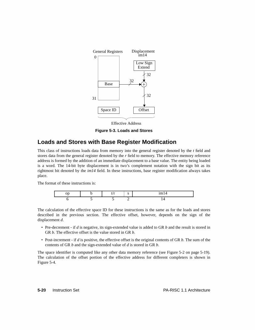
5-20 Instruction Set PA-RISC 1.1 Architecture
Loads and Stores with Base Register ModificationThis class of instructions loads data from memory into the general register denoted by thet field andstores data from the general register denoted by ther field to memory. The effective memory referenceaddress is formed by the addition of an immediate displacement to a base value. The entity being loadedis a word. The 14-bit byte displacement is in two’s complement notation with the sign bit as itsrightmost bit denoted by theim14 field. In these instructions, base register modification always takesplace.
The format of these instructions is:
The calculation of the effective space ID for these instructions is the same as for the loads and storesdescribed in the previous section. The effective offset, however, depends on the sign of thedisplacementd.
• Pre-decrement - ifd is negative, its sign-extended value is added to GRb and the result is stored inGR b. The effective offset is the value stored in GRb.
• Post-increment - ifd is positive, the effective offset is the original contents of GRb. The sum of thecontents of GRb and the sign-extended value ofd is stored in GRb.
The space identifier is computed like any other data memory reference (see Figure 5-2 on page 5-19).The calculation of the offset portion of the effective address for different completers is shown inFigure 5-4.
Figure 5-3. Loads and Stores
op b t/r s im14
6 5 5 2 14
Displacement
Effective Address
Space ID
General Registers0
Base
Low Sign
Offset
32
31
Extend
im14
32
32
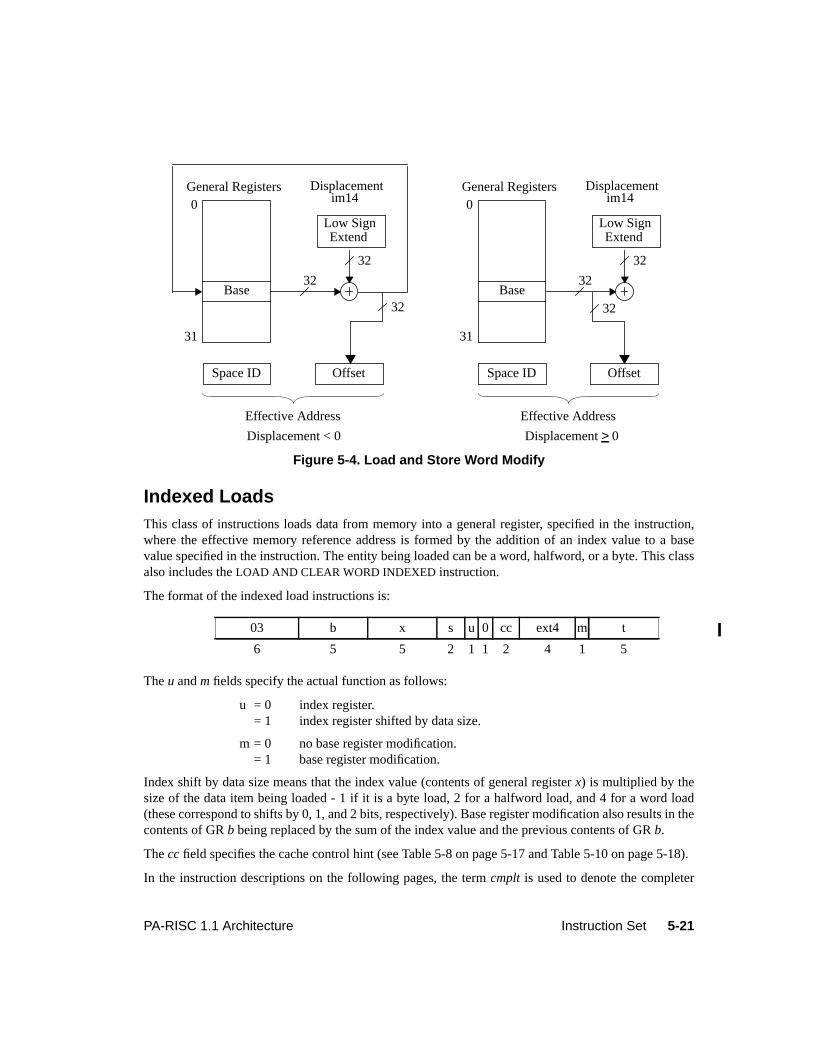
5-21PA-RISC 1.1 Architecture Instruction Set
Indexed LoadsThis class of instructions loads data from memory into a general register, specified in the instruction,where the effective memory reference address is formed by the addition of an index value to a basevalue specified in the instruction. The entity being loaded can be a word, halfword, or a byte. This classalso includes theLOAD AND CLEAR WORD INDEXED instruction.
The format of the indexed load instructions is:
Theu andm fields specify the actual function as follows:
u = 0 index register.= 1 index register shifted by data size.
m = 0 no base register modification.= 1 base register modification.
Index shift by data size means that the index value (contents of general registerx) is multiplied by thesize of the data item being loaded - 1 if it is a byte load, 2 for a halfword load, and 4 for a word load(these correspond to shifts by 0, 1, and 2 bits, respectively). Base register modification also results in thecontents of GRb being replaced by the sum of the index value and the previous contents of GRb.
Thecc field specifies the cache control hint (see Table 5-8 on page 5-17 and Table 5-10 on page 5-18).
In the instruction descriptions on the following pages, the termcmplt is used to denote the completer
Figure 5-4. Load and Store Word Modify
03 b x s u 0 cc ext4 m t
6 5 5 2 1 1 2 4 1 5
Displacement
Effective Address
Space ID
General Registers0
Base
Low Sign
Offset
32
31
Extend
im14
32
32
Displacement
Effective Address
Space ID
General Registers0
Base
Low Sign
Offset
32
31
Extend
im14
32
32
Displacement < 0 Displacement> 0
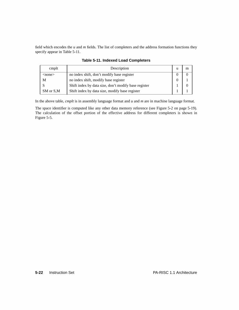
5-22 Instruction Set PA-RISC 1.1 Architecture
field which encodes theu andm fields. The list of completers and the address formation functions theyspecify appear in Table 5-11.
In the above table,cmplt is in assembly language format andu andm are in machine language format.
The space identifier is computed like any other data memory reference (see Figure 5-2 on page 5-19).The calculation of the offset portion of the effective address for different completers is shown inFigure 5-5.
Table 5-11. Indexed Load Completers
cmplt Description u m
<none> no index shift, don’t modify base register 0 0
M no index shift, modify base register 0 1
S Shift index by data size, don’t modify base register 1 0
SM or S,M Shift index by data size, modify base register 1 1
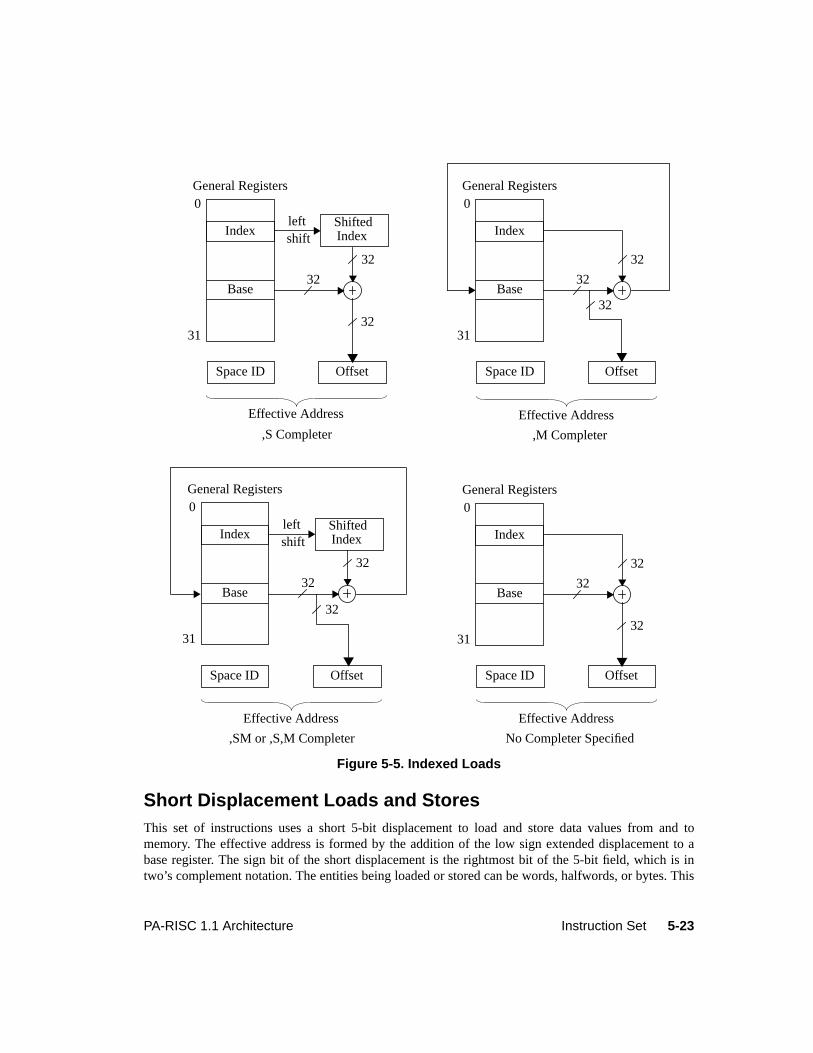
5-23PA-RISC 1.1 Architecture Instruction Set
Short Displacement Loads and StoresThis set of instructions uses a short 5-bit displacement to load and store data values from and tomemory. The effective address is formed by the addition of the low sign extended displacement to abase register. The sign bit of the short displacement is the rightmost bit of the 5-bit field, which is intwo’s complement notation. The entities being loaded or stored can be words, halfwords, or bytes. This
Figure 5-5. Indexed Loads
Effective AddressEffective Address
,S Completer ,M Completer
Effective Address
Space ID Offset
left
Effective Address
Space ID
General Registers0
Base
Shifted
Offset
32
31
Indexshift
32
32
,SM or ,S,M Completer No Completer Specified
Index
General Registers0
Base32
31
32
32
Index
Space ID Offset
left
General Registers0
Base
Shifted
32
31
Indexshift
32
32
Index
Space ID Offset
General Registers0
Base32
31
32
Index
32
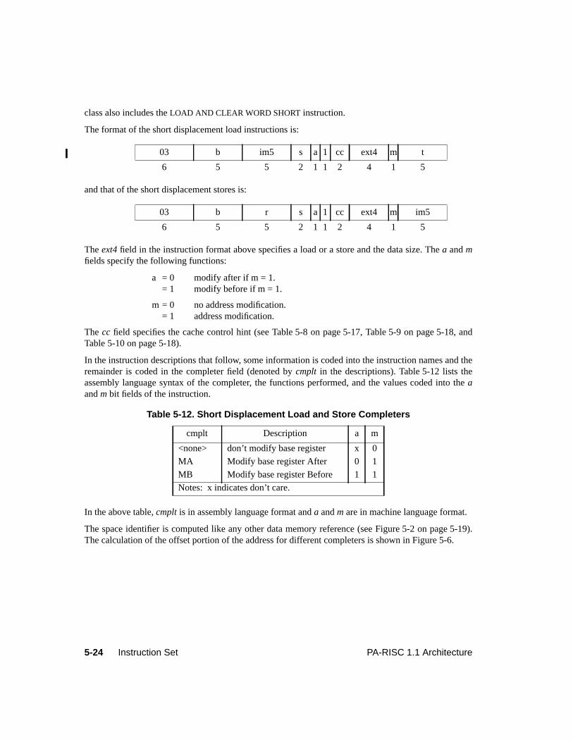
5-24 Instruction Set PA-RISC 1.1 Architecture
class also includes theLOAD AND CLEAR WORD SHORT instruction.
The format of the short displacement load instructions is:
and that of the short displacement stores is:
Theext4 field in the instruction format above specifies a load or a store and the data size. Thea andmfields specify the following functions:
a = 0 modify after if m = 1.= 1 modify before if m = 1.
m = 0 no address modification.= 1 address modification.
The cc field specifies the cache control hint (see Table 5-8 on page 5-17, Table 5-9 on page 5-18, andTable 5-10 on page 5-18).
In the instruction descriptions that follow, some information is coded into the instruction names and theremainder is coded in the completer field (denoted bycmplt in the descriptions). Table 5-12 lists theassembly language syntax of the completer, the functions performed, and the values coded into theaandm bit fields of the instruction.
In the above table,cmplt is in assembly language format anda andm are in machine language format.
The space identifier is computed like any other data memory reference (see Figure 5-2 on page 5-19).The calculation of the offset portion of the address for different completers is shown in Figure 5-6.
03 b im5 s a 1 cc ext4 m t
6 5 5 2 1 1 2 4 1 5
03 b r s a 1 cc ext4 m im5
6 5 5 2 1 1 2 4 1 5
Table 5-12. Short Displacement Load and Store Completers
cmplt Description a m
<none> don’t modify base register x 0
MA Modify base register After 0 1
MB Modify base register Before 1 1
Notes: x indicates don’t care.
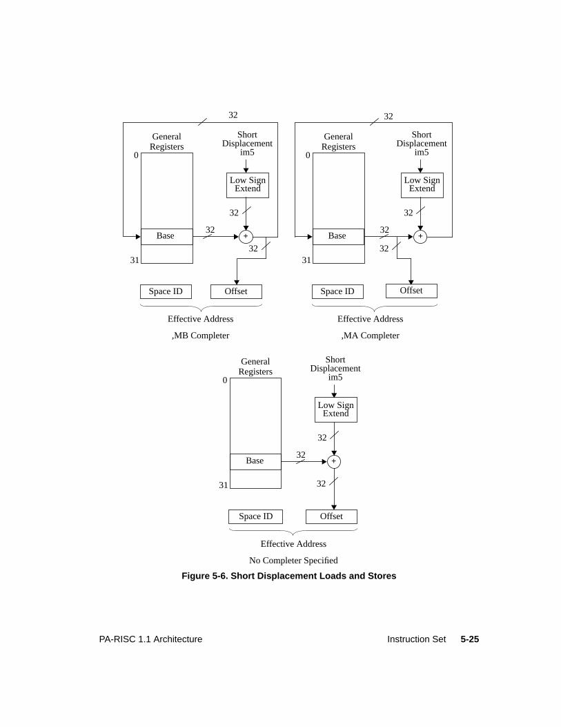
5-25PA-RISC 1.1 Architecture Instruction Set
Figure 5-6. Short Displacement Loads and Stores
0
31
Base
GeneralRegisters
32+
32
32
32
ShortDisplacement
im5
Space ID Offset
Low SignExtend
Effective Address
,MB Completer
0
31
Base
GeneralRegisters
32+
32
32
32
ShortDisplacement
im5
Space ID Offset
Low SignExtend
0
31
Base
GeneralRegisters
32+
32
32
ShortDisplacement
im5
Space ID Offset
Low SignExtend
Effective Address
,MA Completer
Effective Address
No Completer Specified
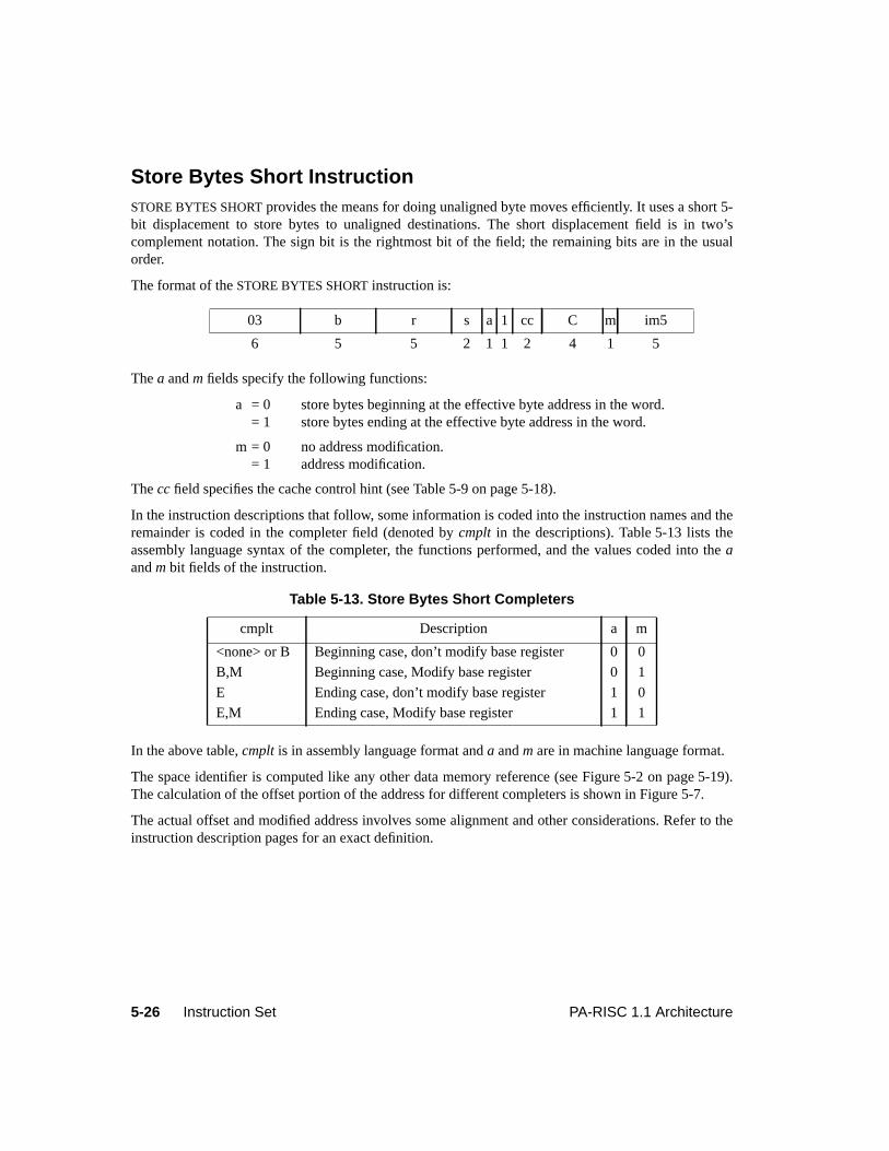
5-26 Instruction Set PA-RISC 1.1 Architecture
Store Bytes Short InstructionSTORE BYTES SHORT provides the means for doing unaligned byte moves efficiently. It uses a short 5-bit displacement to store bytes to unaligned destinations. The short displacement field is in two’scomplement notation. The sign bit is the rightmost bit of the field; the remaining bits are in the usualorder.
The format of theSTORE BYTES SHORT instruction is:
Thea andm fields specify the following functions:
a = 0 store bytes beginning at the effective byte address in the word.= 1 store bytes ending at the effective byte address in the word.
m = 0 no address modification.= 1 address modification.
Thecc field specifies the cache control hint (see Table 5-9 on page 5-18).
In the instruction descriptions that follow, some information is coded into the instruction names and theremainder is coded in the completer field (denoted bycmplt in the descriptions). Table 5-13 lists theassembly language syntax of the completer, the functions performed, and the values coded into theaandm bit fields of the instruction.
In the above table,cmplt is in assembly language format anda andm are in machine language format.
The space identifier is computed like any other data memory reference (see Figure 5-2 on page 5-19).The calculation of the offset portion of the address for different completers is shown in Figure 5-7.
The actual offset and modified address involves some alignment and other considerations. Refer to theinstruction description pages for an exact definition.
03 b r s a 1 cc C m im5
6 5 5 2 1 1 2 4 1 5
Table 5-13. Store Bytes Short Completers
cmplt Description a m
<none> or B Beginning case, don’t modify base register 0 0
B,M Beginning case, Modify base register 0 1
E Ending case, don’t modify base register 1 0
E,M Ending case, Modify base register 1 1
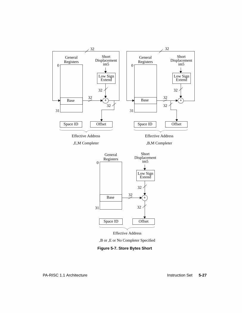
5-27PA-RISC 1.1 Architecture Instruction Set
Figure 5-7. Store Bytes Short
0
31
Base
GeneralRegisters
32+
32
32
32
ShortDisplacement
im5
Space ID Offset
Low SignExtend
Effective Address
,E,M Completer
0
31
Base
GeneralRegisters
32+
32
32
32
ShortDisplacement
im5
Space ID Offset
Low SignExtend
0
31
Base
GeneralRegisters
32+
32
32
ShortDisplacement
im5
Space ID Offset
Low SignExtend
Effective Address
,B,M Completer
Effective Address
,B or ,E or No Completer Specified
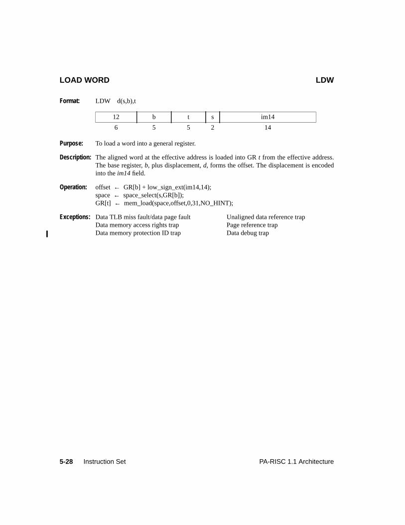
5-28 Instruction Set PA-RISC 1.1 Architecture
LOAD WORD LDW
Format: LDW d(s,b),t
Purpose: To load a word into a general register.
Description: The aligned word at the effective address is loaded into GRt from the effective address.The base register,b, plus displacement,d, forms the offset. The displacement is encodedinto theim14 field.
Operation: offset ← GR[b] + low_sign_ext(im14,14);space← space_select(s,GR[b]);GR[t] ← mem_load(space,offset,0,31,NO_HINT);
Exceptions: Data TLB miss fault/data page fault Unaligned data reference trapData memory access rights trap Page reference trapData memory protection ID trap Data debug trap
12 b t s im14
6 5 5 2 14
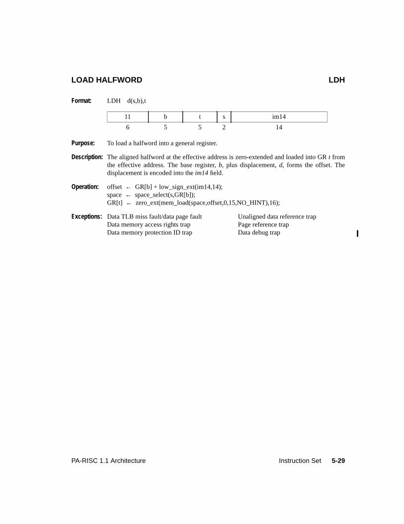
5-29PA-RISC 1.1 Architecture Instruction Set
LOAD HALFWORD LDH
Format: LDH d(s,b),t
Purpose: To load a halfword into a general register.
Description: The aligned halfword at the effective address is zero-extended and loaded into GRt fromthe effective address. The base register,b, plus displacement,d, forms the offset. Thedisplacement is encoded into theim14 field.
Operation: offset ← GR[b] + low_sign_ext(im14,14);space← space_select(s,GR[b]);GR[t] ← zero_ext(mem_load(space,offset,0,15,NO_HINT),16);
Exceptions: Data TLB miss fault/data page fault Unaligned data reference trapData memory access rights trap Page reference trapData memory protection ID trap Data debug trap
11 b t s im14
6 5 5 2 14
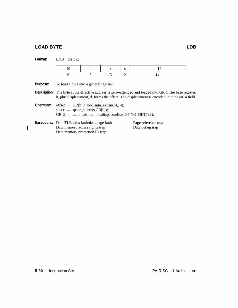
5-30 Instruction Set PA-RISC 1.1 Architecture
LOAD BYTE LDB
Format: LDB d(s,b),t
Purpose: To load a byte into a general register.
Description: The byte at the effective address is zero-extended and loaded into GRt. The base register,b, plus displacement,d, forms the offset. The displacement is encoded into theim14 field.
Operation: offset ← GR[b] + low_sign_ext(im14,14);space← space_select(s,GR[b]);GR[t] ← zero_ext(mem_load(space,offset,0,7,NO_HINT),8);
Exceptions: Data TLB miss fault/data page fault Page reference trapData memory access rights trap Data debug trapData memory protection ID trap
10 b t s im14
6 5 5 2 14
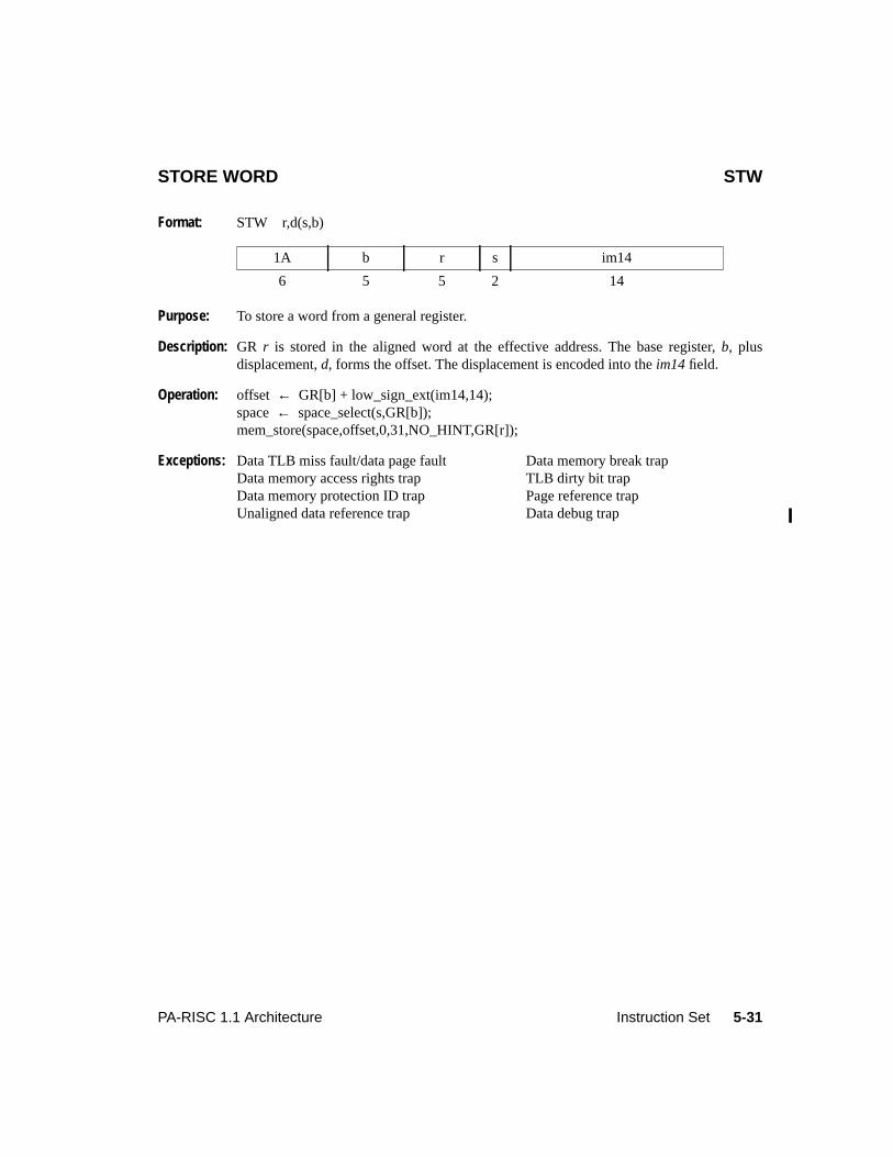
5-31PA-RISC 1.1 Architecture Instruction Set
STORE WORD STW
Format: STW r,d(s,b)
Purpose: To store a word from a general register.
Description: GR r is stored in the aligned word at the effective address. The base register,b, plusdisplacement,d, forms the offset. The displacement is encoded into theim14 field.
Operation: offset ← GR[b] + low_sign_ext(im14,14);space← space_select(s,GR[b]);mem_store(space,offset,0,31,NO_HINT,GR[r]);
Exceptions: Data TLB miss fault/data page fault Data memory break trapData memory access rights trap TLB dirty bit trapData memory protection ID trap Page reference trapUnaligned data reference trap Data debug trap
1A b r s im14
6 5 5 2 14
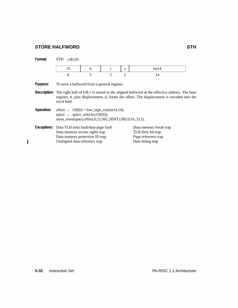
5-32 Instruction Set PA-RISC 1.1 Architecture
STORE HALFWORD STH
Format: STH r,d(s,b)
Purpose: To store a halfword from a general register.
Description: The right half of GRr is stored in the aligned halfword at the effective address. The baseregister,b, plus displacement,d, forms the offset. The displacement is encoded into theim14 field.
Operation: offset ← GR[b] + low_sign_ext(im14,14);space← space_select(s,GR[b]);mem_store(space,offset,0,15,NO_HINT,GR[r]{16..31});
Exceptions: Data TLB miss fault/data page fault Data memory break trapData memory access rights trap TLB dirty bit trapData memory protection ID trap Page reference trapUnaligned data reference trap Data debug trap
19 b r s im14
6 5 5 2 14
5-33PA-RISC 1.1 Architecture Instruction Set
STORE BYTE STB
Format: STB r,d(s,b)
Purpose: To store a byte from a general register.
Description: The rightmost byte of GRr is stored in the byte at the effective address. The base register,b, plus displacement,d, forms the offset. The displacement is encoded into theim14 field.
Operation: offset ← GR[b] + low_sign_ext(im14,14);space← space_select(s,GR[b]);mem_store(space,offset,0,7,NO_HINT,GR[r]{24..31})
Exceptions: Data TLB miss fault/data page fault TLB dirty bit trapData memory access rights trap Page reference trapData memory protection ID trap Data debug trapData memory break trap
18 b r s im14
6 5 5 2 14
5-34 Instruction Set PA-RISC 1.1 Architecture
LOAD WORD AND MODIFY LDWM
Format: LDWM d(s,b),t
Purpose: To load a word into a general register and perform base register modification.
Description: The aligned word at the effective address is loaded into GRt from the effective address.The offset is either the base register,b, (positive displacement) or the base register plus thedisplacement,d, (negative displacement). The displacement is encoded into theim14 field.Base register modification always occurs. Ifb = t, the value loaded is the aligned word atthe effective address.
Operation: if (low_sign_ext(im14,14) < 0)offset ← GR[b] + low_sign_ext(im14,14);
elseoffset ← GR[b];
space← space_select(s,GR[b]);GR[b] ← GR[b] + low_sign_ext(im14,14);GR[t] ← mem_load(space,offset,0,31,NO_HINT);
Exceptions: Data TLB miss fault/data page fault Unaligned data reference trapData memory access rights trap Page reference trapData memory protection ID trap Data debug trap
13 b t s im14
6 5 5 2 14
5-35PA-RISC 1.1 Architecture Instruction Set
STORE WORD AND MODIFY STWM
Format: STWM r,d(s,b)
Purpose: To store a word from a general register and perform base register modification.
Description: GR r is stored in the aligned word at the effective address. The offset is either the baseregister,b, (positive displacement) or the base register plus the displacement,d, (negativedisplacement). The displacement is encoded into theim14 field. Base register modificationalways occurs. Ifb = r, the value stored at the effective address is the word from the sourceregister before modification.
Operation: if (low_sign_ext(im14,14) < 0)offset ← GR[b] + low_sign_ext(im14,14);
elseoffset ← GR[b];
space← space_select(s,GR[b]);mem_store(space,offset,0,31,NO_HINT,GR[r]);GR[b] ← GR[b] + low_sign_ext(im14,14);
Exceptions: Data TLB miss fault/data page fault Data memory break trapData memory access rights trap TLB dirty bit trapData memory protection ID trap Page reference trapUnaligned data reference trap Data debug trap
1B b r s im14
6 5 5 2 14
5-36 Instruction Set PA-RISC 1.1 Architecture
LOAD WORD INDEXED LDWX
Format: LDWX,cmplt,cc x(s,b),t
Purpose: To load a word into a general register.
Description: The aligned word at the effective address is loaded into GRt. The base register,b, and theindex register,x, are combined to form the address offset. The completer,cmplt,determines if the offset is the base register, the base register plus the index register, or thebase register plus the index register shifted by 2. This completer, encoded in theu andmfields of the instruction, also specifies base register modification. (See Table 5-11 onpage 5-22 for the assembly language completer mnemonics.) If base register modificationis specified andb = t, the value loaded is the aligned word at the effective address.
The completer,cc, specifies the cache control hint (see Table 5-8 on page 5-17).
Operation: space← space_select(s,GR[b]);switch (cmplt) {
case S: offset← GR[b] + lshift(GR[x],2); /*u=1, m=0*/break;
case M: offset← GR[b]; /*u=0, m=1*/GR[b] ← GR[b] + GR[x];break;
case SM: offset← GR[b]; /*u=1, m=1*/GR[b] ← GR[b] + lshift(GR[x],2);break;
default: offset← GR[b] + GR[x]; /*u=0, m=0*/break;
}GR[t] ← mem_load(space,offset,0,31,cc);
Exceptions: Data TLB miss fault/data page fault Unaligned data reference trapData memory access rights trap Page reference trapData memory protection ID trap Data debug trap
03 b x s u 0 cc 2 m t
6 5 5 2 1 1 2 4 1 5
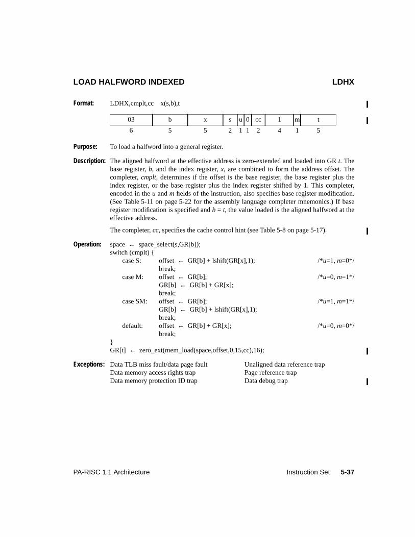
5-37PA-RISC 1.1 Architecture Instruction Set
LOAD HALFWORD INDEXED LDHX
Format: LDHX,cmplt,cc x(s,b),t
Purpose: To load a halfword into a general register.
Description: The aligned halfword at the effective address is zero-extended and loaded into GRt. Thebase register,b, and the index register,x, are combined to form the address offset. Thecompleter,cmplt, determines if the offset is the base register, the base register plus theindex register, or the base register plus the index register shifted by 1. This completer,encoded in theu andm fields of the instruction, also specifies base register modification.(See Table 5-11 on page 5-22 for the assembly language completer mnemonics.) If baseregister modification is specified andb = t, the value loaded is the aligned halfword at theeffective address.
The completer,cc, specifies the cache control hint (see Table 5-8 on page 5-17).
Operation: space← space_select(s,GR[b]);switch (cmplt) {
case S: offset← GR[b] + lshift(GR[x],1); /*u=1, m=0*/break;
case M: offset← GR[b]; /*u=0, m=1*/GR[b] ← GR[b] + GR[x];break;
case SM: offset← GR[b]; /*u=1, m=1*/GR[b] ← GR[b] + lshift(GR[x],1);break;
default: offset← GR[b] + GR[x]; /*u=0, m=0*/break;
}GR[t] ← zero_ext(mem_load(space,offset,0,15,cc),16);
Exceptions: Data TLB miss fault/data page fault Unaligned data reference trapData memory access rights trap Page reference trapData memory protection ID trap Data debug trap
03 b x s u 0 cc 1 m t
6 5 5 2 1 1 2 4 1 5
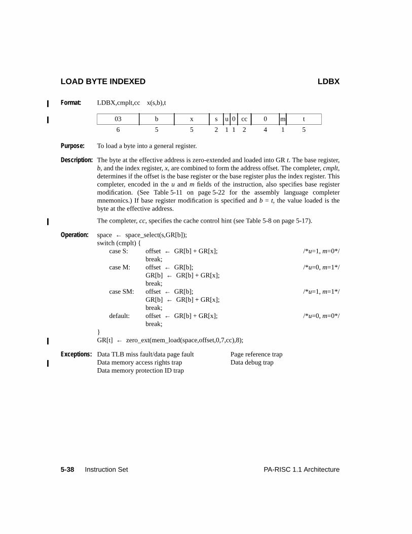
5-38 Instruction Set PA-RISC 1.1 Architecture
LOAD BYTE INDEXED LDBX
Format: LDBX,cmplt,cc x(s,b),t
Purpose: To load a byte into a general register.
Description: The byte at the effective address is zero-extended and loaded into GRt. The base register,b, and the index register,x, are combined to form the address offset. The completer,cmplt,determines if the offset is the base register or the base register plus the index register. Thiscompleter, encoded in theu andm fields of the instruction, also specifies base registermodification. (See Table 5-11 on page 5-22 for the assembly language completermnemonics.) If base register modification is specified andb = t, the value loaded is thebyte at the effective address.
The completer,cc, specifies the cache control hint (see Table 5-8 on page 5-17).
Operation: space← space_select(s,GR[b]);switch (cmplt) {
case S: offset← GR[b] + GR[x]; /*u=1, m=0*/break;
case M: offset← GR[b]; /*u=0, m=1*/GR[b] ← GR[b] + GR[x];break;
case SM: offset← GR[b]; /*u=1, m=1*/GR[b] ← GR[b] + GR[x];break;
default: offset← GR[b] + GR[x]; /*u=0, m=0*/break;
}GR[t] ← zero_ext(mem_load(space,offset,0,7,cc),8);
Exceptions: Data TLB miss fault/data page fault Page reference trapData memory access rights trap Data debug trapData memory protection ID trap
03 b x s u 0 cc 0 m t
6 5 5 2 1 1 2 4 1 5
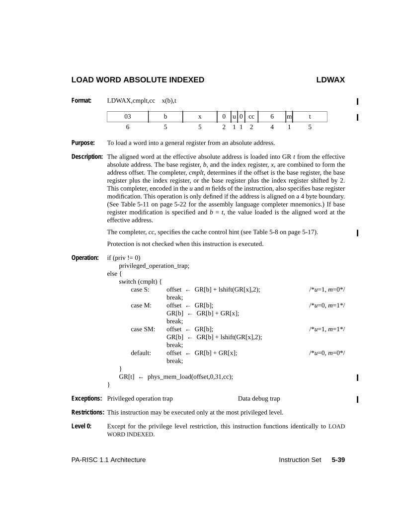
5-39PA-RISC 1.1 Architecture Instruction Set
LOAD WORD ABSOLUTE INDEXED LDWAX
Format: LDWAX,cmplt,cc x(b),t
Purpose: To load a word into a general register from an absolute address.
Description: The aligned word at the effective absolute address is loaded into GRt from the effectiveabsolute address. The base register,b, and the index register,x, are combined to form theaddress offset. The completer,cmplt, determines if the offset is the base register, the baseregister plus the index register, or the base register plus the index register shifted by 2.This completer, encoded in theu andm fields of the instruction, also specifies base registermodification. This operation is only defined if the address is aligned on a 4 byte boundary.(See Table 5-11 on page 5-22 for the assembly language completer mnemonics.) If baseregister modification is specified andb = t, the value loaded is the aligned word at theeffective address.
The completer,cc, specifies the cache control hint (see Table 5-8 on page 5-17).
Protection is not checked when this instruction is executed.
Operation: if (priv != 0)privileged_operation_trap;
else {switch (cmplt) {
case S: offset← GR[b] + lshift(GR[x],2); /*u=1, m=0*/break;
case M: offset← GR[b]; /*u=0, m=1*/GR[b] ← GR[b] + GR[x];break;
case SM: offset← GR[b]; /*u=1, m=1*/GR[b] ← GR[b] + lshift(GR[x],2);break;
default: offset← GR[b] + GR[x]; /*u=0, m=0*/break;
}GR[t] ← phys_mem_load(offset,0,31,cc);
}
Exceptions: Privileged operation trap Data debug trap
Restrictions: This instruction may be executed only at the most privileged level.
Level 0: Except for the privilege level restriction, this instruction functions identically toLOADWORD INDEXED.
03 b x 0 u 0 cc 6 m t
6 5 5 2 1 1 2 4 1 5

5-40 Instruction Set PA-RISC 1.1 Architecture
LOAD AND CLEAR WORD INDEXED LDCWX
Format: LDCWX,cmplt,cc x(s,b),t
Purpose: To read and lock a semaphore in main memory.
Description: The effective address is calculated. The base register,b, and the index register,x, arecombined to form the address offset. The completer,cmplt, determines if the offset is thebase register, the base register plus the index register, or the base register plus the indexregister shifted by 3. This completer, encoded in theu andm fields of the instruction, alsospecifies base register modification. (See Table 5-11 on page 5-22 for the assemblylanguage completer mnemonics.) If base register modification is specified andb = t, thevalue loaded is the aligned word at the effective address.
The completer,cc, specifies the cache control hint (see Table 5-10 on page 5-18).
The address must be 16-byte aligned. If the address is unaligned, the operation of theinstruction is undefined.
The remaining steps of the instruction are indivisible and non-interruptible. If a cachecontrol hint is not specified, the instruction is performed as follows:
• If the cache line containing the effective address is not present in the cache or ispresent but not dirty, and the system is not fully coherent, the line is flushed, theaddressed word is copied into GRt, and then set to zero in memory. If the line isretained in the cache, it must not be marked as dirty.
• If the cache line containing the effective address is present in the cache and is dirty, orthe system is fully coherent, the semaphore operation may be handled as above ormay be optimized by copying the addressed word into GRt and then setting theaddressed word to zero in the cache.
If a cache control hint is specified, the semaphore operation may be handled as if a cachecontrol hint had not been specified, or, preferably, the addressed word is copied into GRtand then the addressed word is set to zero in the cache. The cleared word need not beflushed to memory.
Operation: space← space_select(s,GR[b]);switch (cmplt) {
case S: offset← GR[b] + lshift(GR[x],3); /*u=1, m=0*/break;
case M: offset← GR[b]; /*u=0, m=1*/GR[b] ← GR[b] + GR[x];break;
case SM: offset← GR[b]; /*u=1, m=1*/GR[b] ← GR[b] + lshift(GR[x],3);
03 b x s u 0 cc 7 m t
6 5 5 2 1 1 2 4 1 5
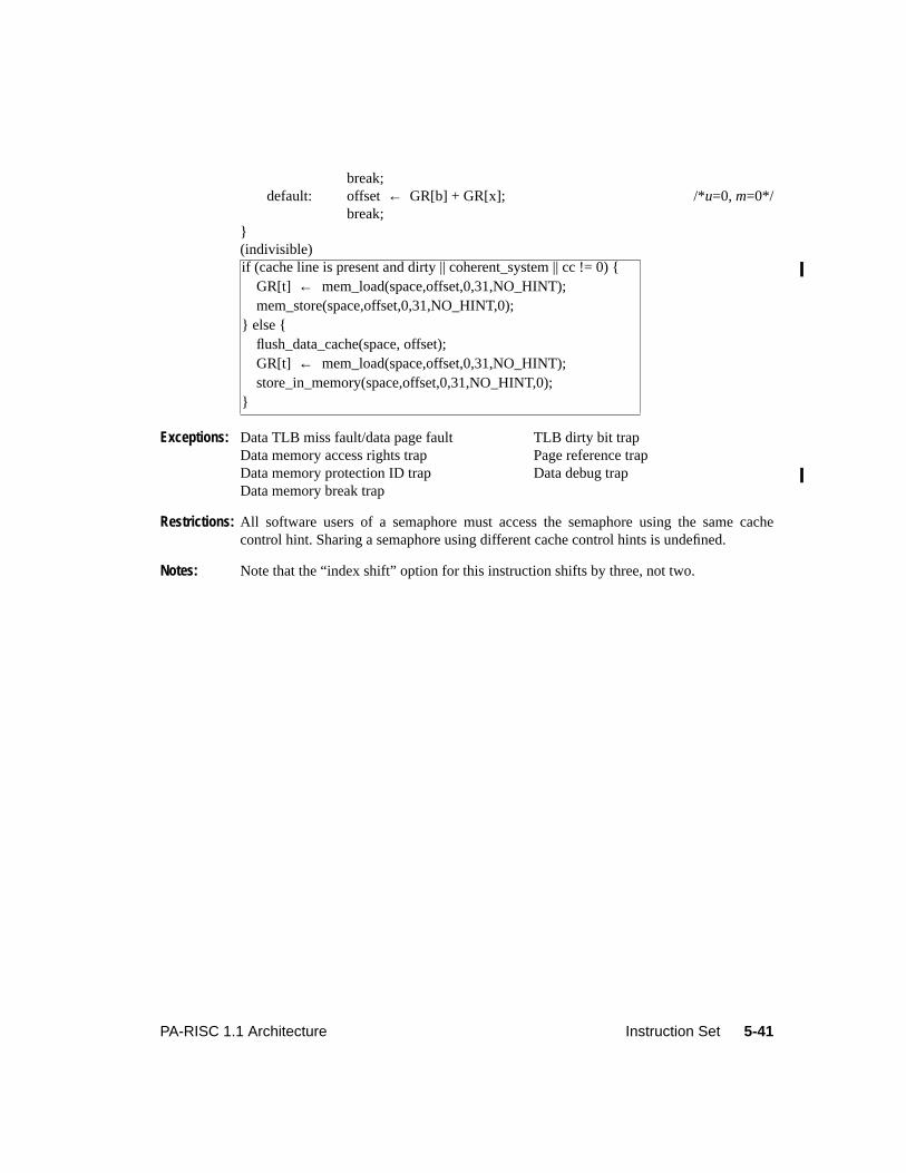
5-41PA-RISC 1.1 Architecture Instruction Set
break;default: offset← GR[b] + GR[x]; /*u=0, m=0*/
break;}(indivisible)
Exceptions: Data TLB miss fault/data page fault TLB dirty bit trapData memory access rights trap Page reference trapData memory protection ID trap Data debug trapData memory break trap
Restrictions: All software users of a semaphore must access the semaphore using the same cachecontrol hint. Sharing a semaphore using different cache control hints is undefined.
Notes: Note that the “index shift” option for this instruction shifts by three, not two.
if (cache line is present and dirty || coherent_system || cc != 0) { GR[t] ← mem_load(space,offset,0,31,NO_HINT); mem_store(space,offset,0,31,NO_HINT,0);} else { flush_data_cache(space, offset); GR[t] ← mem_load(space,offset,0,31,NO_HINT); store_in_memory(space,offset,0,31,NO_HINT,0);}
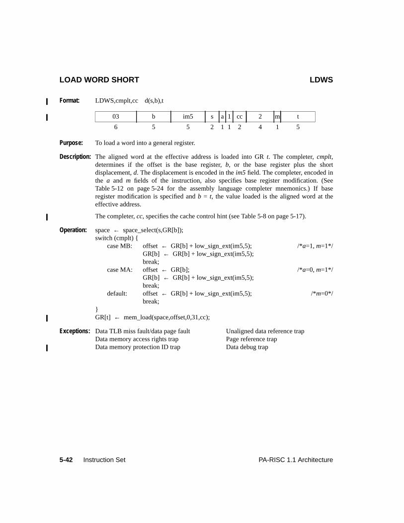
5-42 Instruction Set PA-RISC 1.1 Architecture
LOAD WORD SHORT LDWS
Format: LDWS,cmplt,cc d(s,b),t
Purpose: To load a word into a general register.
Description: The aligned word at the effective address is loaded into GRt. The completer,cmplt,determines if the offset is the base register,b, or the base register plus the shortdisplacement,d. The displacement is encoded in theim5 field. The completer, encoded inthe a and m fields of the instruction, also specifies base register modification. (SeeTable 5-12 on page 5-24 for the assembly language completer mnemonics.) If baseregister modification is specified andb = t, the value loaded is the aligned word at theeffective address.
The completer,cc, specifies the cache control hint (see Table 5-8 on page 5-17).
Operation: space← space_select(s,GR[b]);switch (cmplt) {
case MB: offset← GR[b] + low_sign_ext(im5,5); /*a=1, m=1*/GR[b] ← GR[b] + low_sign_ext(im5,5);break;
case MA: offset← GR[b]; /*a=0, m=1*/GR[b] ← GR[b] + low_sign_ext(im5,5);break;
default: offset← GR[b] + low_sign_ext(im5,5); /*m=0*/break;
}GR[t] ← mem_load(space,offset,0,31,cc);
Exceptions: Data TLB miss fault/data page fault Unaligned data reference trapData memory access rights trap Page reference trapData memory protection ID trap Data debug trap
03 b im5 s a 1 cc 2 m t
6 5 5 2 1 1 2 4 1 5
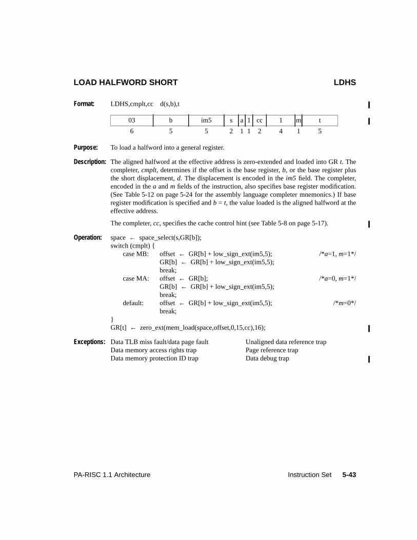
5-43PA-RISC 1.1 Architecture Instruction Set
LOAD HALFWORD SHORT LDHS
Format: LDHS,cmplt,cc d(s,b),t
Purpose: To load a halfword into a general register.
Description: The aligned halfword at the effective address is zero-extended and loaded into GRt. Thecompleter,cmplt, determines if the offset is the base register,b, or the base register plusthe short displacement,d. The displacement is encoded in theim5 field. The completer,encoded in thea andm fields of the instruction, also specifies base register modification.(See Table 5-12 on page 5-24 for the assembly language completer mnemonics.) If baseregister modification is specified andb = t, the value loaded is the aligned halfword at theeffective address.
The completer,cc, specifies the cache control hint (see Table 5-8 on page 5-17).
Operation: space← space_select(s,GR[b]);switch (cmplt) {
case MB: offset← GR[b] + low_sign_ext(im5,5); /*a=1, m=1*/GR[b] ← GR[b] + low_sign_ext(im5,5);break;
case MA: offset← GR[b]; /*a=0, m=1*/GR[b] ← GR[b] + low_sign_ext(im5,5);break;
default: offset← GR[b] + low_sign_ext(im5,5); /*m=0*/break;
}GR[t] ← zero_ext(mem_load(space,offset,0,15,cc),16);
Exceptions: Data TLB miss fault/data page fault Unaligned data reference trapData memory access rights trap Page reference trapData memory protection ID trap Data debug trap
03 b im5 s a 1 cc 1 m t
6 5 5 2 1 1 2 4 1 5
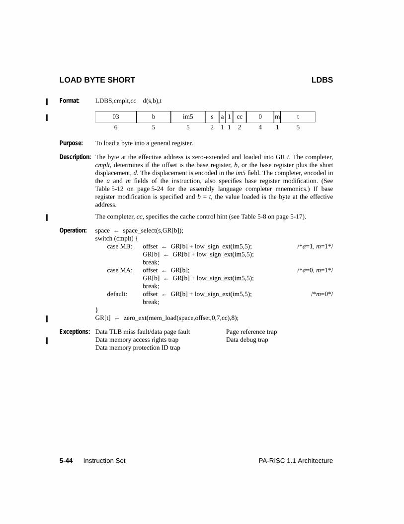
5-44 Instruction Set PA-RISC 1.1 Architecture
LOAD BYTE SHORT LDBS
Format: LDBS,cmplt,cc d(s,b),t
Purpose: To load a byte into a general register.
Description: The byte at the effective address is zero-extended and loaded into GRt. The completer,cmplt, determines if the offset is the base register,b, or the base register plus the shortdisplacement,d. The displacement is encoded in theim5 field. The completer, encoded inthe a and m fields of the instruction, also specifies base register modification. (SeeTable 5-12 on page 5-24 for the assembly language completer mnemonics.) If baseregister modification is specified andb = t, the value loaded is the byte at the effectiveaddress.
The completer,cc, specifies the cache control hint (see Table 5-8 on page 5-17).
Operation: space← space_select(s,GR[b]);switch (cmplt) {
case MB: offset← GR[b] + low_sign_ext(im5,5); /*a=1, m=1*/GR[b] ← GR[b] + low_sign_ext(im5,5);break;
case MA: offset← GR[b]; /*a=0, m=1*/GR[b] ← GR[b] + low_sign_ext(im5,5);break;
default: offset← GR[b] + low_sign_ext(im5,5); /*m=0*/break;
}GR[t] ← zero_ext(mem_load(space,offset,0,7,cc),8);
Exceptions: Data TLB miss fault/data page fault Page reference trapData memory access rights trap Data debug trapData memory protection ID trap
03 b im5 s a 1 cc 0 m t
6 5 5 2 1 1 2 4 1 5
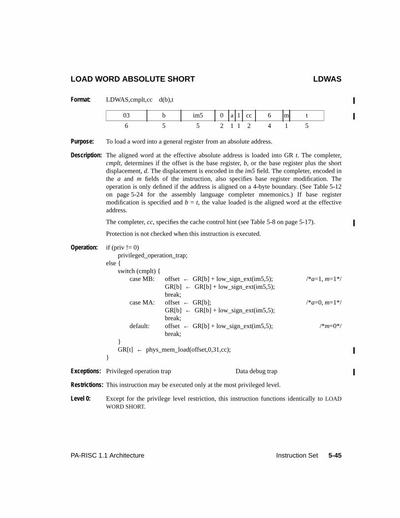
5-45PA-RISC 1.1 Architecture Instruction Set
LOAD WORD ABSOLUTE SHORT LDWAS
Format: LDWAS,cmplt,cc d(b),t
Purpose: To load a word into a general register from an absolute address.
Description: The aligned word at the effective absolute address is loaded into GRt. The completer,cmplt, determines if the offset is the base register,b, or the base register plus the shortdisplacement,d. The displacement is encoded in theim5 field. The completer, encoded inthe a and m fields of the instruction, also specifies base register modification. Theoperation is only defined if the address is aligned on a 4-byte boundary. (See Table 5-12on page 5-24 for the assembly language completer mnemonics.) If base registermodification is specified andb = t, the value loaded is the aligned word at the effectiveaddress.
The completer,cc, specifies the cache control hint (see Table 5-8 on page 5-17).
Protection is not checked when this instruction is executed.
Operation: if (priv != 0)privileged_operation_trap;
else {switch (cmplt) {
case MB: offset← GR[b] + low_sign_ext(im5,5); /*a=1, m=1*/GR[b] ← GR[b] + low_sign_ext(im5,5);break;
case MA: offset← GR[b]; /*a=0, m=1*/GR[b] ← GR[b] + low_sign_ext(im5,5);break;
default: offset← GR[b] + low_sign_ext(im5,5); /*m=0*/break;
}GR[t] ← phys_mem_load(offset,0,31,cc);
}
Exceptions: Privileged operation trap Data debug trap
Restrictions: This instruction may be executed only at the most privileged level.
Level 0: Except for the privilege level restriction, this instruction functions identically toLOADWORD SHORT.
03 b im5 0 a 1 cc 6 m t
6 5 5 2 1 1 2 4 1 5
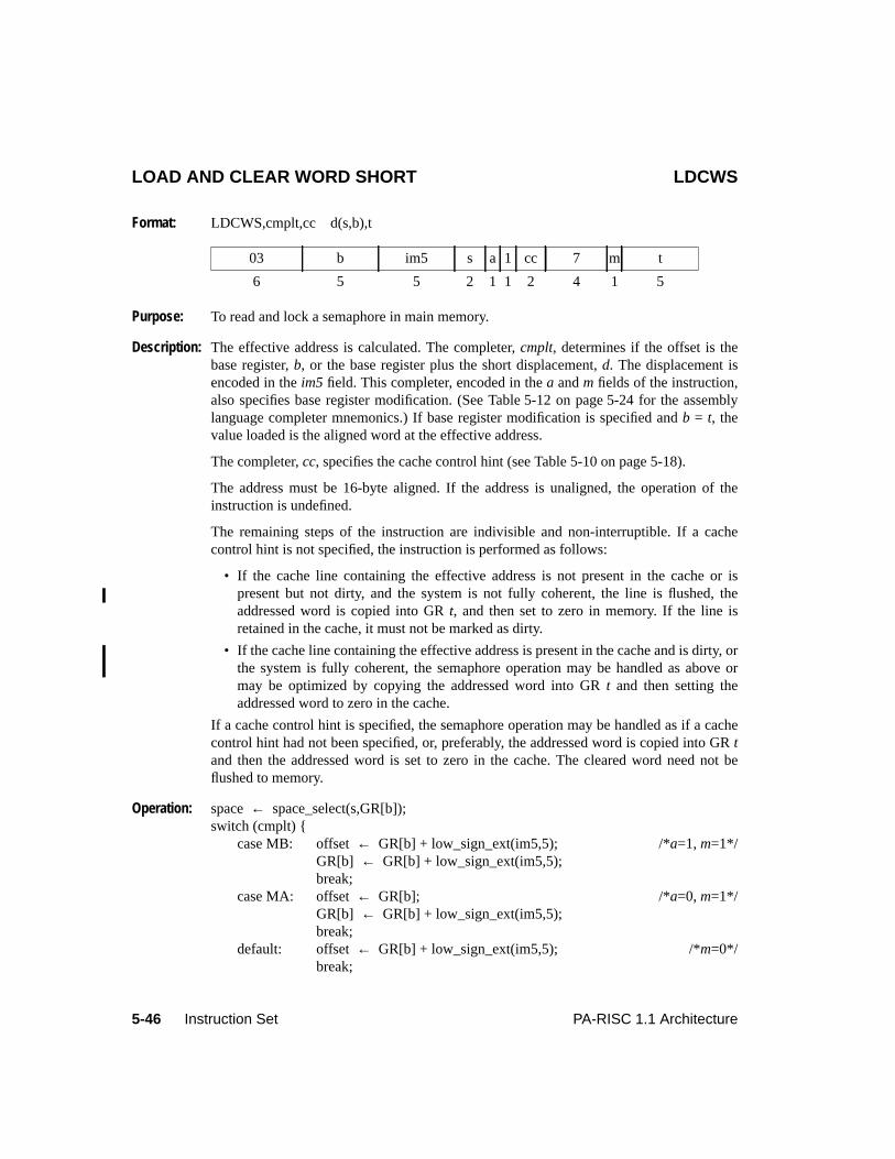
5-46 Instruction Set PA-RISC 1.1 Architecture
LOAD AND CLEAR WORD SHORT LDCWS
Format: LDCWS,cmplt,cc d(s,b),t
Purpose: To read and lock a semaphore in main memory.
Description: The effective address is calculated. The completer,cmplt, determines if the offset is thebase register,b, or the base register plus the short displacement,d. The displacement isencoded in theim5 field. This completer, encoded in thea andm fields of the instruction,also specifies base register modification. (See Table 5-12 on page 5-24 for the assemblylanguage completer mnemonics.) If base register modification is specified andb = t, thevalue loaded is the aligned word at the effective address.
The completer,cc, specifies the cache control hint (see Table 5-10 on page 5-18).
The address must be 16-byte aligned. If the address is unaligned, the operation of theinstruction is undefined.
The remaining steps of the instruction are indivisible and non-interruptible. If a cachecontrol hint is not specified, the instruction is performed as follows:
• If the cache line containing the effective address is not present in the cache or ispresent but not dirty, and the system is not fully coherent, the line is flushed, theaddressed word is copied into GRt, and then set to zero in memory. If the line isretained in the cache, it must not be marked as dirty.
• If the cache line containing the effective address is present in the cache and is dirty, orthe system is fully coherent, the semaphore operation may be handled as above ormay be optimized by copying the addressed word into GRt and then setting theaddressed word to zero in the cache.
If a cache control hint is specified, the semaphore operation may be handled as if a cachecontrol hint had not been specified, or, preferably, the addressed word is copied into GRtand then the addressed word is set to zero in the cache. The cleared word need not beflushed to memory.
Operation: space← space_select(s,GR[b]);switch (cmplt) {
case MB: offset← GR[b] + low_sign_ext(im5,5); /*a=1, m=1*/GR[b] ← GR[b] + low_sign_ext(im5,5);break;
case MA: offset← GR[b]; /*a=0, m=1*/GR[b] ← GR[b] + low_sign_ext(im5,5);break;
default: offset← GR[b] + low_sign_ext(im5,5); /*m=0*/break;
03 b im5 s a 1 cc 7 m t
6 5 5 2 1 1 2 4 1 5
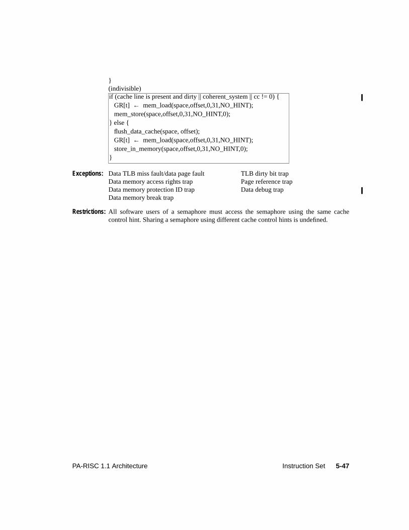
5-47PA-RISC 1.1 Architecture Instruction Set
}(indivisible)
Exceptions: Data TLB miss fault/data page fault TLB dirty bit trapData memory access rights trap Page reference trapData memory protection ID trap Data debug trapData memory break trap
Restrictions: All software users of a semaphore must access the semaphore using the same cachecontrol hint. Sharing a semaphore using different cache control hints is undefined.
if (cache line is present and dirty || coherent_system || cc != 0) { GR[t] ← mem_load(space,offset,0,31,NO_HINT); mem_store(space,offset,0,31,NO_HINT,0);} else { flush_data_cache(space, offset); GR[t] ← mem_load(space,offset,0,31,NO_HINT); store_in_memory(space,offset,0,31,NO_HINT,0);}
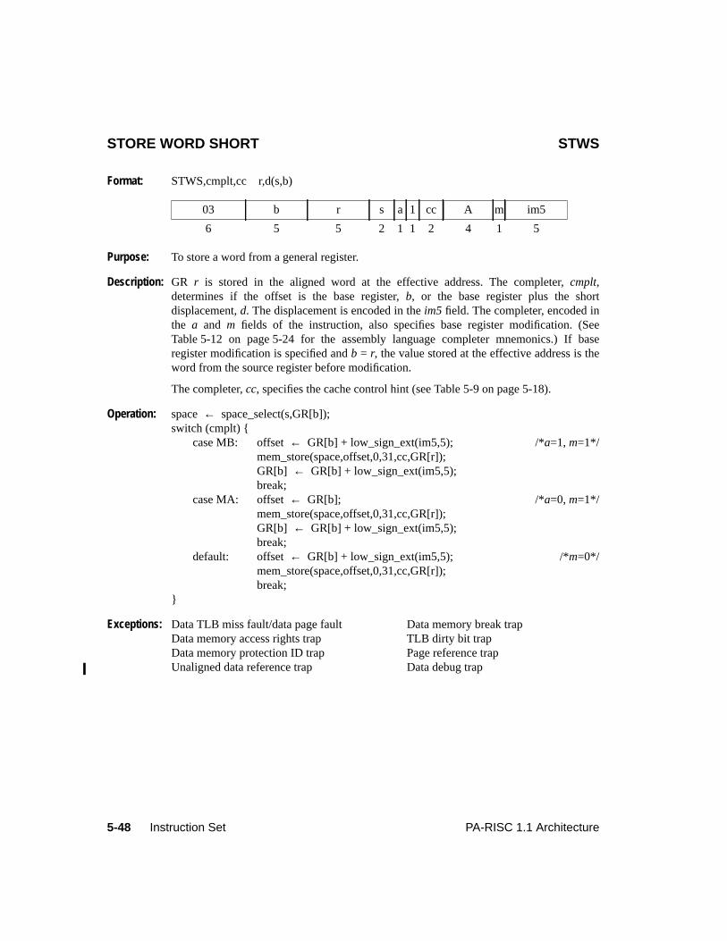
5-48 Instruction Set PA-RISC 1.1 Architecture
STORE WORD SHORT STWS
Format: STWS,cmplt,cc r,d(s,b)
Purpose: To store a word from a general register.
Description: GR r is stored in the aligned word at the effective address. The completer,cmplt,determines if the offset is the base register,b, or the base register plus the shortdisplacement,d. The displacement is encoded in theim5 field. The completer, encoded inthe a and m fields of the instruction, also specifies base register modification. (SeeTable 5-12 on page 5-24 for the assembly language completer mnemonics.) If baseregister modification is specified andb = r, the value stored at the effective address is theword from the source register before modification.
The completer,cc, specifies the cache control hint (see Table 5-9 on page 5-18).
Operation: space← space_select(s,GR[b]);switch (cmplt) {
case MB: offset← GR[b] + low_sign_ext(im5,5); /*a=1, m=1*/mem_store(space,offset,0,31,cc,GR[r]);GR[b] ← GR[b] + low_sign_ext(im5,5);break;
case MA: offset← GR[b]; /*a=0, m=1*/mem_store(space,offset,0,31,cc,GR[r]);GR[b] ← GR[b] + low_sign_ext(im5,5);break;
default: offset← GR[b] + low_sign_ext(im5,5); /*m=0*/mem_store(space,offset,0,31,cc,GR[r]);break;
}
Exceptions: Data TLB miss fault/data page fault Data memory break trapData memory access rights trap TLB dirty bit trapData memory protection ID trap Page reference trapUnaligned data reference trap Data debug trap
03 b r s a 1 cc A m im5
6 5 5 2 1 1 2 4 1 5
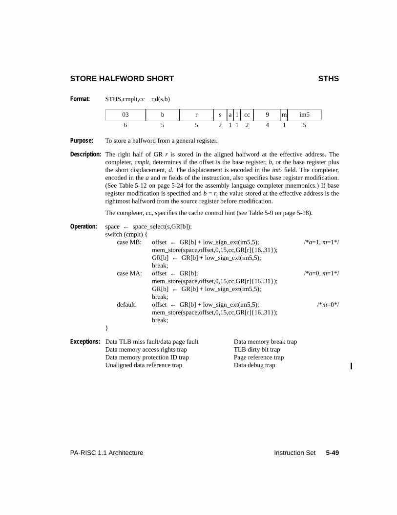
5-49PA-RISC 1.1 Architecture Instruction Set
STORE HALFWORD SHORT STHS
Format: STHS,cmplt,cc r,d(s,b)
Purpose: To store a halfword from a general register.
Description: The right half of GRr is stored in the aligned halfword at the effective address. Thecompleter,cmplt, determines if the offset is the base register,b, or the base register plusthe short displacement,d. The displacement is encoded in theim5 field. The completer,encoded in thea andm fields of the instruction, also specifies base register modification.(See Table 5-12 on page 5-24 for the assembly language completer mnemonics.) If baseregister modification is specified andb = r, the value stored at the effective address is therightmost halfword from the source register before modification.
The completer,cc, specifies the cache control hint (see Table 5-9 on page 5-18).
Operation: space← space_select(s,GR[b]);switch (cmplt) {
case MB: offset← GR[b] + low_sign_ext(im5,5); /*a=1, m=1*/mem_store(space,offset,0,15,cc,GR[r]{16..31});GR[b] ← GR[b] + low_sign_ext(im5,5);break;
case MA: offset← GR[b]; /*a=0, m=1*/mem_store(space,offset,0,15,cc,GR[r]{16..31});GR[b] ← GR[b] + low_sign_ext(im5,5);break;
default: offset← GR[b] + low_sign_ext(im5,5); /*m=0*/mem_store(space,offset,0,15,cc,GR[r]{16..31});break;
}
Exceptions: Data TLB miss fault/data page fault Data memory break trapData memory access rights trap TLB dirty bit trapData memory protection ID trap Page reference trapUnaligned data reference trap Data debug trap
03 b r s a 1 cc 9 m im5
6 5 5 2 1 1 2 4 1 5
5-50 Instruction Set PA-RISC 1.1 Architecture
STORE BYTE SHORT STBS
Format: STBS,cmplt,cc r,d(s,b)
Purpose: To store a byte from a general register.
Description: The rightmost byte of GRr is stored in the byte at the effective address. The completer,cmplt, determines if the offset is the base register,b, or the base register plus the shortdisplacement,d. The displacement is encoded in theim5 field. The completer, encoded inthe a and m fields of the instruction, also specifies base register modification. (SeeTable 5-12 on page 5-24 for the assembly language completer mnemonics.) If baseregister modification is specified andb = r, the value stored at the effective address is therightmost byte from the source register before modification.
The completer,cc, specifies the cache control hint (see Table 5-9 on page 5-18).
Operation: space← space_select(s,GR[b]);switch (cmplt) {
case MB: offset← GR[b] + low_sign_ext(im5,5); /*a=1, m=1*/mem_store(space,offset,0,7,cc,GR[r]{24..31});GR[b] ← GR[b] + low_sign_ext(im5,5);break;
case MA: offset← GR[b]; /*a=0, m=1*/mem_store(space,offset,0,7,cc,GR[r]{24..31});GR[b] ← GR[b] + low_sign_ext(im5,5);break;
default: offset← GR[b] + low_sign_ext(im5,5); /*m=0*/mem_store(space,offset,0,7,cc,GR[r]{24..31});break;
}
Exceptions: Data TLB miss fault/data page fault TLB dirty bit trapData memory access rights trap Page reference trapData memory protection ID trap Data debug trapData memory break trap
03 b r s a 1 cc 8 m im5
6 5 5 2 1 1 2 4 1 5
5-51PA-RISC 1.1 Architecture Instruction Set
STORE WORD ABSOLUTE SHORT STWAS
Format: STWAS,cmplt,cc r,d(b)
Purpose: To store a word from a general register to an absolute address.
Description: GR r is stored in the aligned word at the effective absolute address. The completer,cmplt,determines if the offset is the base register,b, or the base register plus the shortdisplacement,d. The displacement is encoded in theim5 field. The completer, encoded inthe a and m fields of the instruction, also specifies base register modification. Theoperation is only defined if the address is aligned on a 4-byte boundary. (See Table 5-12on page 5-24 for the assembly language completer mnemonics.) If base registermodification is specified andb = r, the value stored at the effective address is the wordfrom the source register before modification.
The completer,cc, specifies the cache control hint (see Table 5-9 on page 5-18).
Protection is not checked when this instruction is executed.
Operation: if (priv != 0)privileged_operation_trap;
else {switch (cmplt) {
case MB: offset← GR[b] + low_sign_ext(im5,5); /*a=1, m=1*/phys_mem_store(offset,0,31,cc,GR[r]);GR[b] ← GR[b] + low_sign_ext(im5,5);break;
case MA: offset← GR[b]; /*a=0, m=1*/phys_mem_store(offset,0,31,cc,GR[r]);GR[b] ← GR[b] + low_sign_ext(im5,5);break;
default: offset← GR[b] + low_sign_ext(im5,5); /*m=0*/phys_mem_store(offset,0,31,cc,GR[r]);break;
}}
Exceptions: Privileged operation trap Data debug trap
Restrictions: This instruction may be executed only at the most privileged level.
Level 0: Except for the privilege level restriction, this instruction functions identically toSTOREWORD SHORT.
03 b r 0 a 1 cc E m im5
6 5 5 2 1 1 2 4 1 5
5-52 Instruction Set PA-RISC 1.1 Architecture
STORE BYTES SHORT STBYS
Format: STBYS,cmplt,cc r,d(s,b)
Purpose: To implement the beginning, middle, and ending cases for fast byte moves with unalignedsources and destinations.
Description: If the PSW[E] bit is 0 and begin (modifier ",B" corresponding toa = 0) is specified, therightmost bytes of GRr are stored in memory starting at the byte whose address is givenby the effective address. The number of bytes stored is sufficient to fill out the wordcontaining the byte addressed by the effective address.
If the PSW[E] bit is 0 and end (modifier ",E" corresponding toa = 1) is specified, theleftmost bytes of GRr are stored in memory starting at the leftmost byte in the wordspecified by the effective address, and continuing until (but not including) the bytespecified by the effective address. When the effective address specifies the leftmost byte ina word, nothing is stored, but protection is checked and the cache line is marked asdirty.
If the PSW[E] bit is 1 and begin (modifier ",B" corresponding toa = 0) is specified, theleftmost bytes of GRr are stored in memory starting at the byte whose address is given bythe effective address. The number of bytes stored is sufficient to fill out the wordcontaining the byte addressed by the effective address.
If the PSW[E] bit is 1 and end (modifier ",E" corresponding toa = 1) is specified, therightmost bytes of GRr are stored in memory starting at the leftmost byte in the wordspecified by the effective address, and continuing until (but not including) the bytespecified by the effective address. When the effective address specifies the leftmost byte ina word, nothing is stored, but protection is checked and the cache line is marked asdirty.
If base register modification is specified through completer ",M", GRb is updated and thentruncated to a word address. (See Table 5-13 on page 5-26 for the assembly languagecompleter mnemonics.) If base register modification is specified andb = r, the valuestored at the effective address is the bytes from the source register before modification.
The completer,cc, specifies the cache control hint (see Table 5-9 on page 5-18). If the firstbyte of the addressed cache line is not written to, the processor must perform the store as ifthe cache control hint had not been specified.
Operation: space← space_select(s,GR[b]);if (cmplt == B,M) /*a=0, m=1*/
offset ← GR[b];else
offset ← GR[b] + low_sign_ext(im5,5);pos ← 8*(offset & 0x3);offset ← offset & 0xFFFFFFFC;
03 b r s a 1 cc C m im5
6 5 5 2 1 1 2 4 1 5
5-53PA-RISC 1.1 Architecture Instruction Set
switch (cmplt) {case B: /*a=0, m=0*/
if (PSW[E] == 0)mem_store(space,offset,pos,31,cc,GR[r]{pos..31});
elsemem_store(space,offset,pos,31,cc,GR[r]{0..31-pos});
break;case E: /*a=1, m=0*/
if (PSW[E] == 0)mem_store(space,offset,0,pos-1,cc,GR[r]{0..pos-1});
elsemem_store(space,offset,0,pos-1,cc,GR[r]{32-pos..31});
break;case B,M: /*a=0, m=1*/
if (PSW[E] == 0)mem_store(space,offset,pos,31,cc,GR[r]{pos..31});
elsemem_store(space,offset,pos,31,cc,GR[r]{0..31-pos});
GR[b] ← (GR[b] + low_sign_ext(im5,5)) & 0xFFFFFFFC;break;
case E,M: /*a=1, m=1*/if (PSW[E] == 0)
mem_store(space,offset,0,pos-1,cc,GR[r]{0..pos-1});else
mem_store(space,offset,0,pos-1,cc,GR[r]{32-pos..31});GR[b] ← (GR[b] + low_sign_ext(im5,5)) & 0xFFFFFFFC;break;
}
Exceptions: Data TLB miss fault/data page fault TLB dirty bit trapData memory access rights trap Page reference trapData memory protection ID trap Data debug trapData memory break trap
Notes: All 32 bits of the original virtual offset are saved to IOR (CR21) if this instruction traps.
For this instruction, the low 2 bits of the virtual offset are masked to 0 when comparingagainst the contents of the data breakpoint address offset registers.
PROGRAMMING NOTEThe STBYS instruction with the ’,E’ completer and the effective address specifying theleftmost byte of the word may be used to implement a memory scrubbing operation. This ispossible because the line is markeddirty but the contents are not modified.
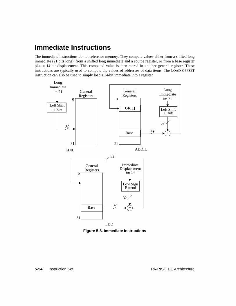
5-54 Instruction Set PA-RISC 1.1 Architecture
5Instruction Set
Immediate InstructionsThe immediate instructions do not reference memory. They compute values either from a shifted longimmediate (21 bits long), from a shifted long immediate and a source register, or from a base registerplus a 14-bit displacement. This computed value is then stored in another general register. Theseinstructions are typically used to compute the values of addresses of data items. TheLOAD OFFSETinstruction can also be used to simply load a 14-bit immediate into a register.
Figure 5-8. Immediate Instructions
0
31
Base
GeneralRegisters
32+
32
Left Shift11 bits
ADDIL
GR[1]
0
31
GeneralRegisters
LDIL
LDO
Left Shift11 bits
32
LongImmediate
im 21
0
31
Base
GeneralRegisters
32+
32
ImmediateDisplacement
im 14
Low SignExtend
32
LongImmediate
im 21
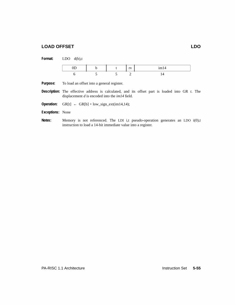
5-55PA-RISC 1.1 Architecture Instruction Set
LOAD OFFSET LDO
Format: LDO d(b),t
Purpose: To load an offset into a general register.
Description: The effective address is calculated, and its offset part is loaded into GRt. Thedisplacementd is encoded into theim14 field.
Operation: GR[t] ← GR[b] + low_sign_ext(im14,14);
Exceptions: None
Notes: Memory is not referenced. TheLDI i,t pseudo-operation generates anLDO i(0),tinstruction to load a 14-bit immediate value into a register.
0D b t rv im14
6 5 5 2 14
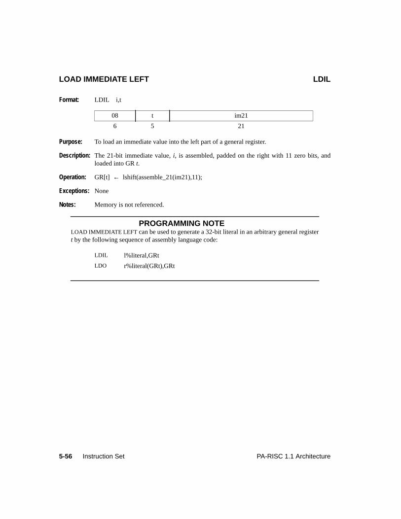
5-56 Instruction Set PA-RISC 1.1 Architecture
LOAD IMMEDIATE LEFT LDIL
Format: LDIL i,t
Purpose: To load an immediate value into the left part of a general register.
Description: The 21-bit immediate value,i, is assembled, padded on the right with 11 zero bits, andloaded into GRt.
Operation: GR[t] ← lshift(assemble_21(im21),11);
Exceptions: None
Notes: Memory is not referenced.
PROGRAMMING NOTELOAD IMMEDIATE LEFT can be used to generate a 32-bit literal in an arbitrary general registert by the following sequence of assembly language code:
08 t im21
6 5 21
LDIL l%literal,GRt
LDO r%literal(GRt),GRt
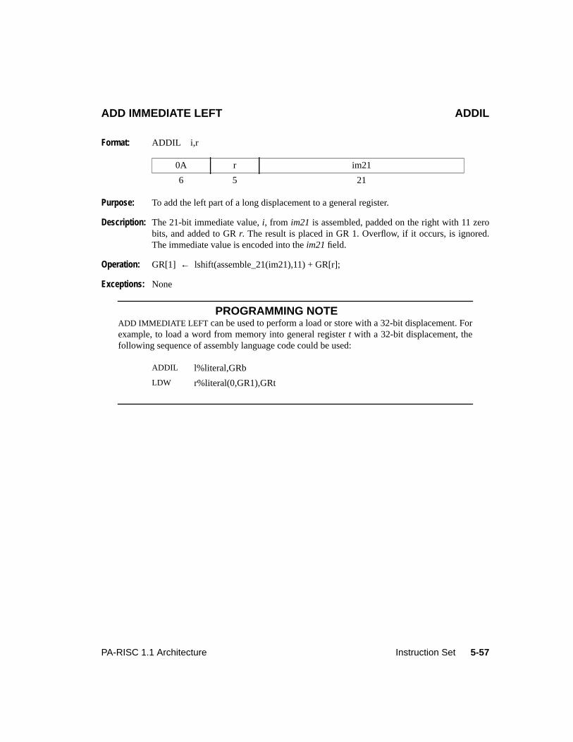
5-57PA-RISC 1.1 Architecture Instruction Set
ADD IMMEDIATE LEFT ADDIL
Format: ADDIL i,r
Purpose: To add the left part of a long displacement to a general register.
Description: The 21-bit immediate value,i, from im21 is assembled, padded on the right with 11 zerobits, and added to GRr. The result is placed in GR 1. Overflow, if it occurs, is ignored.The immediate value is encoded into theim21 field.
Operation: GR[1] ← lshift(assemble_21(im21),11) + GR[r];
Exceptions: None
PROGRAMMING NOTEADD IMMEDIATE LEFT can be used to perform a load or store with a 32-bit displacement. Forexample, to load a word from memory into general registert with a 32-bit displacement, thefollowing sequence of assembly language code could be used:
0A r im21
6 5 21
ADDIL l%literal,GRb
LDW r%literal(0,GR1),GRt
5-58 Instruction Set PA-RISC 1.1 Architecture
5Instruction Set
Branch InstructionsBranch instructions are classified into three major categories: unconditional local branches,unconditional external branches, and conditional local branches. Within these categories there is sub-classification based on how the target address is computed, whether or not a return address is saved, andwhether or not privilege changes can occur. Not all of the options are available for each category. Thefollowing sections describe the types of branches. The operation of each branch instruction is detailed inthe instruction description sections in this chapter.
Unconditional Local BranchesThe unconditional local branch instructions are used for intraspace control transfers, procedure calls,and procedure returns. Three types of relative addressing are provided:
1. IA relative branches with static displacement use the IAOQ_Front plus a 17-bit signed worddisplacement. This allows a branch target range of up to plus or minus 256 Kbytes within a space.
2. IA relative branches with dynamic displacement use the IAOQ_Front plus a shifted index register.
3. Base relative branches with dynamic displacement use the value in a base register plus a shiftedindex register.
BRANCH AND LINK is used for procedure calls. The branch target address is IA relative with a staticdisplacement. It places the offset of the return point in the specified GR. The return point is the locationfour bytes beyond the address of the instruction which executes after theBRANCH AND LINK. BRANCHAND LINK also satisfies most requirements for unconditional branching when GR 0 is specified as thelink register.
GATEWAY is used for intraspace branching with a process privilege level promotion. The branch targetaddress is IA relative with a static displacement.
BRANCH AND LINK REGISTER is used for intraspace procedure calls in which the branch target isoutside the range forBRANCH AND LINK or when a dynamic target displacement is needed. The branchtarget address is IA relative with a dynamic displacement. Link handling is performed the same way asfor theBRANCH AND LINK instruction.
BRANCH VECTORED is used for intraspace branching through a table and for procedure returns. Thebranch target is base relative with a dynamic displacement. The process privilege level may bedemoted.
Unconditional External BranchesThe unconditional external branch instructions are used for interspace control transfers, procedure calls,and procedure returns. All unconditional external branch instructions use base-relative addressing withstatic displacements and may demote the process privilege level based on the rightmost bits of the baseregister. The target address is the value in a base register plus a 17-bit signed word displacement. Thisallows for a plus or minus 256 Kbyte branch range across space boundaries.
BRANCH AND LINK EXTERNAL is used for interspace procedure calls. It places the offset of the returnpoint in GR 31 and copies the space ID into SR 0. The return point is the location four bytes beyond the
5-59PA-RISC 1.1 Architecture Instruction Set
address of the instruction which executes after the branch.
BRANCH EXTERNAL is used for interspace branching and procedure returns. The return address is notsaved in this instruction.
In Level 0 systems, unconditional external branch instructions are executed as in non-Level 0 systems,except that the IASQ and SR 0 are nonexistent registers and updating them has no effect.
Conditional Local BranchesThe conditional local branch instructions are used to perform an operation and then branch if thecondition specified is satisfied. All conditional local branch instructions use IA relative addresses withstatic displacements. The target address is the current IAOQ_Front plus a 12-bit signed worddisplacement. This allows for a plus or minus 8-Kbyte branch target range within a space.
There are four categories of conditional local branch instructions: move and branch, compare andbranch, add and branch, and branch on bits. The branch may be taken if the condition specified is true orfalse. There are two forms of each instruction, the two-register form and the register plus 5-bitimmediate form. The 5-bit immediate operand provides data values in the range from -16 to +15.
Branch CharacteristicsFigure 5-9 categorizes the characteristics of the branch instructions.
5-60 Instruction Set PA-RISC 1.1 Architecture
Figure 5-9. Classification of Branch Instructions
BLEBEBV
Branch
Unconditional Conditional
Local External
IARelative
BaseRelative
StaticDisp.
DynamicDisp.
No Link
Local
BaseRelative
IARelative
DynamicDisp.
StaticDisp.
StaticDisp.
Link Link No Link No Link Link No Link
No PLchange
PLchange
No PLchange
PLchange
PLchange
PLchange
No PLchange
MOVBMOVIB
COMBxCOMIBx
ADDBxADDIBx
BBBBV
BL GATE BLR
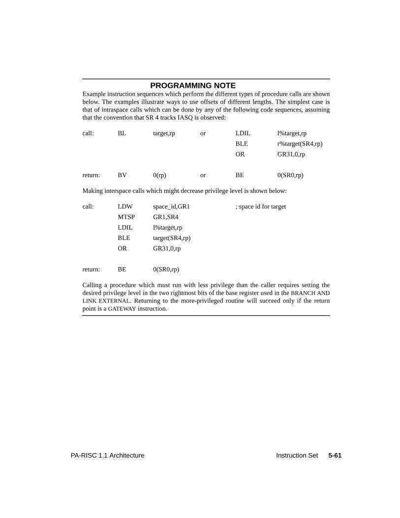
5-61PA-RISC 1.1 Architecture Instruction Set
PROGRAMMING NOTEExample instruction sequences which perform the different types of procedure calls are shownbelow. The examples illustrate ways to use offsets of different lengths. The simplest case isthat of intraspace calls which can be done by any of the following code sequences, assumingthat the convention that SR 4 tracks IASQ is observed:
Making interspace calls which might decrease privilege level is shown below:
Calling a procedure which must run with less privilege than the caller requires setting thedesired privilege level in the two rightmost bits of the base register used in theBRANCH ANDLINK EXTERNAL. Returning to the more-privileged routine will succeed only if the returnpoint is aGATEWAY instruction.
call: BL target,rp or LDIL l%target,rp
BLE r%target(SR4,rp)
OR GR31,0,rp
return: BV 0(rp) or BE 0(SR0,rp)
call: LDW space_id,GR1 ; space id for target
MTSP GR1,SR4
LDIL l%target,rp
BLE target(SR4,rp)
OR GR31,0,rp
return: BE 0(SR0,rp)
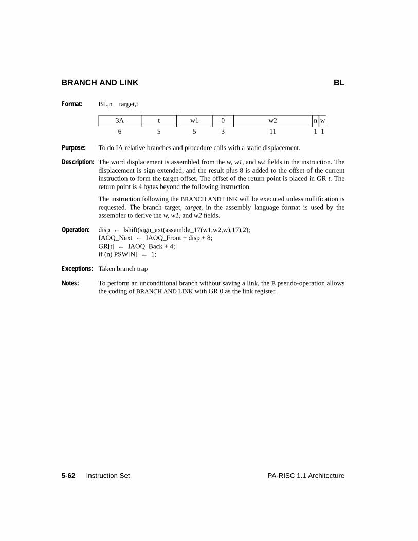
5-62 Instruction Set PA-RISC 1.1 Architecture
BRANCH AND LINK BL
Format: BL,n target,t
Purpose: To do IA relative branches and procedure calls with a static displacement.
Description: The word displacement is assembled from thew, w1, andw2 fields in the instruction. Thedisplacement is sign extended, and the result plus 8 is added to the offset of the currentinstruction to form the target offset. The offset of the return point is placed in GRt. Thereturn point is 4 bytes beyond the following instruction.
The instruction following theBRANCH AND LINK will be executed unless nullification isrequested. The branch target,target, in the assembly language format is used by theassembler to derive thew, w1, andw2 fields.
Operation: disp ← lshift(sign_ext(assemble_17(w1,w2,w),17),2);IAOQ_Next ← IAOQ_Front + disp + 8;GR[t] ← IAOQ_Back + 4;if (n) PSW[N] ← 1;
Exceptions: Taken branch trap
Notes: To perform an unconditional branch without saving a link, theB pseudo-operation allowsthe coding ofBRANCH AND LINK with GR 0 as the link register.
3A t w1 0 w2 n w
6 5 5 3 11 1 1
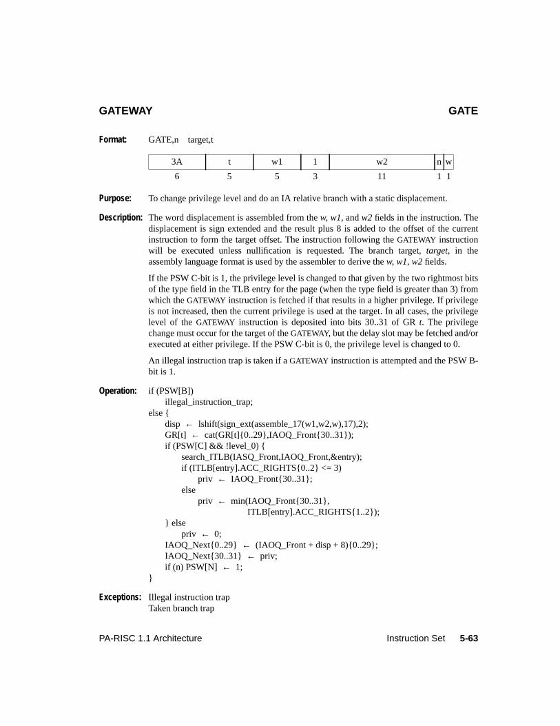
5-63PA-RISC 1.1 Architecture Instruction Set
GATEWAY GATE
Format: GATE,n target,t
Purpose: To change privilege level and do an IA relative branch with a static displacement.
Description: The word displacement is assembled from thew, w1, andw2 fields in the instruction. Thedisplacement is sign extended and the result plus 8 is added to the offset of the currentinstruction to form the target offset. The instruction following theGATEWAY instructionwill be executed unless nullification is requested. The branch target,target, in theassembly language format is used by the assembler to derive thew, w1, w2 fields.
If the PSW C-bit is 1, the privilege level is changed to that given by the two rightmost bitsof the type field in the TLB entry for the page (when the type field is greater than 3) fromwhich theGATEWAY instruction is fetched if that results in a higher privilege. If privilegeis not increased, then the current privilege is used at the target. In all cases, the privilegelevel of theGATEWAY instruction is deposited into bits 30..31 of GRt. The privilegechange must occur for the target of theGATEWAY, but the delay slot may be fetched and/orexecuted at either privilege. If the PSW C-bit is 0, the privilege level is changed to 0.
An illegal instruction trap is taken if aGATEWAY instruction is attempted and the PSW B-bit is 1.
Operation: if (PSW[B])illegal_instruction_trap;
else {disp ← lshift(sign_ext(assemble_17(w1,w2,w),17),2);GR[t] ← cat(GR[t]{0..29},IAOQ_Front{30..31});if (PSW[C] && !level_0) {
search_ITLB(IASQ_Front,IAOQ_Front,&entry);if (ITLB[entry].ACC_RIGHTS{0..2} <= 3)
priv ← IAOQ_Front{30..31};else
priv ← min(IAOQ_Front{30..31},ITLB[entry].ACC_RIGHTS{1..2});
} elsepriv ← 0;
IAOQ_Next{0..29} ← (IAOQ_Front + disp + 8){0..29};IAOQ_Next{30..31} ← priv;if (n) PSW[N] ← 1;
}
Exceptions: Illegal instruction trapTaken branch trap
3A t w1 1 w2 n w
6 5 5 3 11 1 1
5-64 Instruction Set PA-RISC 1.1 Architecture
Notes: The privilege information must be captured when the TLB is read for instruction fetch andthat information kept for the determination of the new execution privilege.
PROGRAMMING NOTEThe privilege level checking for fetching and executing the instruction following aGATEWAY(which might be in a different page from theGATEWAY itself) may be done against either theold or the new privilege level. Software should ensure that both checks are equally valid.
It is possible for aGATEWAY to promote the privilege level so that the process cannot continueexecuting on that page (because it violates PL2 of the TLB access rights field). In that case,software should ensure that theGATEWAY nullifies execution of the following instruction andits target should be on a page whose range of execute levels includes the new privilege level.Otherwise, an instruction memory protection trap may result.
Level 0: This instruction promotes the privilege level to 0.
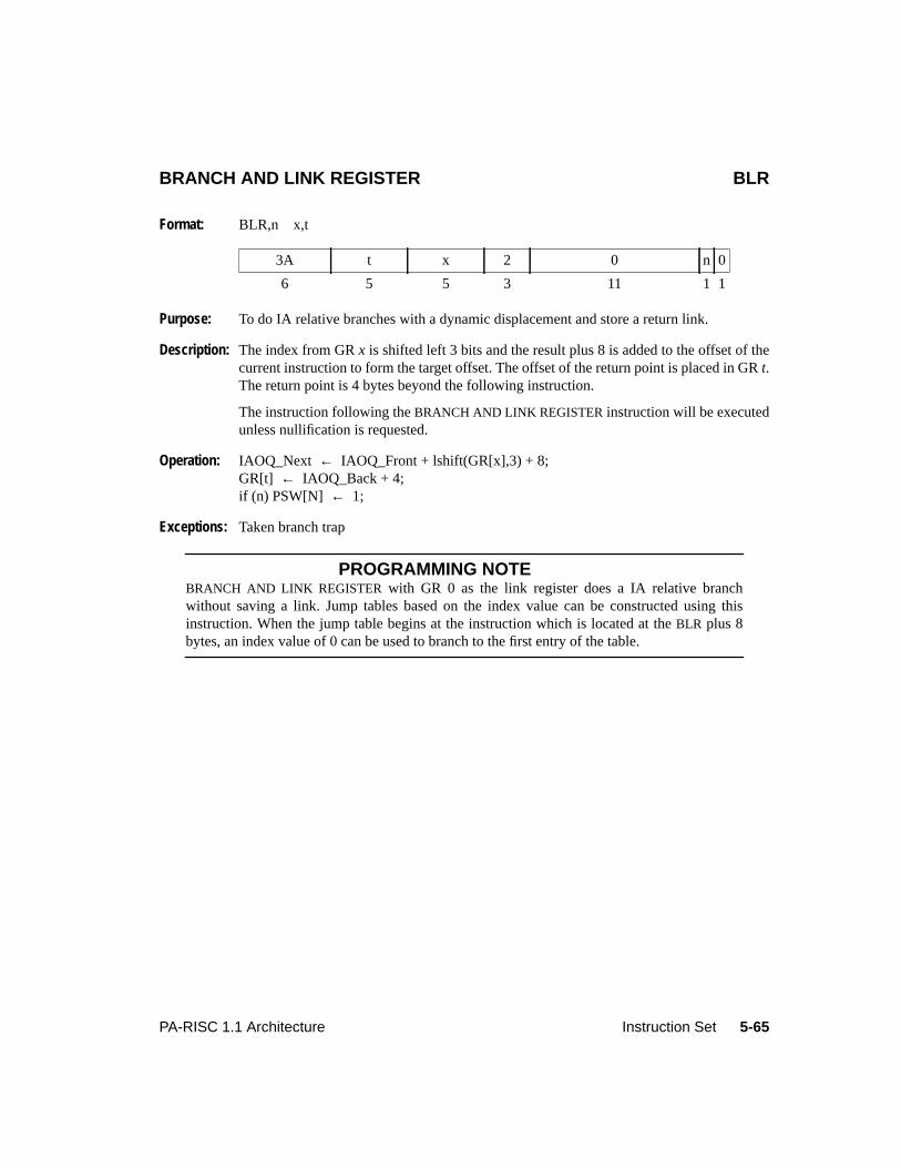
5-65PA-RISC 1.1 Architecture Instruction Set
BRANCH AND LINK REGISTER BLR
Format: BLR,n x,t
Purpose: To do IA relative branches with a dynamic displacement and store a return link.
Description: The index from GRx is shifted left 3 bits and the result plus 8 is added to the offset of thecurrent instruction to form the target offset. The offset of the return point is placed in GRt.The return point is 4 bytes beyond the following instruction.
The instruction following theBRANCH AND LINK REGISTER instruction will be executedunless nullification is requested.
Operation: IAOQ_Next ← IAOQ_Front + lshift(GR[x],3) + 8;GR[t] ← IAOQ_Back + 4;if (n) PSW[N] ← 1;
Exceptions: Taken branch trap
PROGRAMMING NOTEBRANCH AND LINK REGISTER with GR 0 as the link register does a IA relative branchwithout saving a link. Jump tables based on the index value can be constructed using thisinstruction. When the jump table begins at the instruction which is located at theBLR plus 8bytes, an index value of 0 can be used to branch to the first entry of the table.
3A t x 2 0 n 0
6 5 5 3 11 1 1
5-66 Instruction Set PA-RISC 1.1 Architecture
BRANCH VECTORED BV
Format: BV,n x(b)
Purpose: To do base-relative branches with a dynamic displacement in the same space.
Description: The index from GRx is shifted left by 3 bits. The result is added to GRb and the sumbecomes the new offset of the target instruction.
The instruction following theBRANCH VECTORED instruction will be executed unlessnullification is specified.
If the two rightmost bits of GRb designate a lower privilege level than the currentprivilege level, then the privilege level of the target is set to that specified by the rightmostbits of GRb. The decrease in privilege level takes effect at the branch target, not for theinstruction in the delay slot.
Operation: IAOQ_Next{0..29} ← (GR[b] + lshift(GR[x],3)){0..29};if (IAOQ_Front{30..31} < GR[b]{30..31})
IAOQ_Next{30..31} ← GR[b]{30..31};else
IAOQ_Next{30..31} ← IAOQ_Front{30..31};if (n) PSW[N] ← 1;
Exceptions: Taken branch trap
Level 0: This instruction demotes the privilege level to any nonzero value, if it changes it.
3A b x 6 0 n 0
6 5 5 3 11 1 1
5-67PA-RISC 1.1 Architecture Instruction Set
BRANCH EXTERNAL BE
Format: BE,n wd(sr,b)
Purpose: To do branches and returns to another space.
Description: The word displacement,wd, is assembled from thew, w1, andw2 fields in the instructionand sign extended. The result is added to GRb and the sum becomes the offset of thetarget instruction. SRsr (which is assembled from thes field of the instruction) becomesthe space of the target instruction.
If the two rightmost bits of GRb designate a less privileged level than the currentinstruction, the privilege level of the target is set to that specified by the rightmost bits ofGR b. The decrease in privilege level takes effect at the branch target, not for theinstruction in the delay slot. When aBRANCH EXTERNAL is executed with the PSW C-bit0 (code address translation is disabled) the effect on IASQ is not defined.
Operation: disp ← lshift(sign_ext(assemble_17(w1,w2,w),17),2);IAOQ_Next{0..29} ← (GR[b] + disp){0..29};if (IAOQ_Front{30..31} < GR[b]{30..31})
IAOQ_Next{30..31} ← GR[b]{30..31};else
IAOQ_Next{30..31} ← IAOQ_Front{30..31};IASQ_Next ← SR[assemble_3(s)];if (n) PSW[N] ← 1;
Exceptions: Taken branch trap
Level 0: This instruction executes as usual, except that the IASQ is a nonexistent register andupdating it has no effect. Also, the privilege level is demoted to any nonzero value, if theinstruction changes it.
PROGRAMMING NOTEIf a taken local branch is executed following aBRANCH EXTERNAL instruction, the target’saddress is computed based on the value of the IASQ set by theBRANCH EXTERNALinstruction. This results in a transfer of control to possibly a meaningless location in the newspace.
38 b w1 s w2 n w
6 5 5 3 11 1 1
5-68 Instruction Set PA-RISC 1.1 Architecture
BRANCH AND LINK EXTERNAL BLE
Format: BLE,n wd(sr,b)
Purpose: To do procedure calls to another space.
Description: The word displacement,wd, is assembled from thew, w1, andw2 fields in the instructionand sign extended. The result is added to GRb and the sum becomes the offset of thetarget instruction. SRsr (which is assembled from thes field of the instruction) becomesthe space of the target instruction. The offset of the return point is placed in GR 31 and thespace portion of the following instruction’s address is placed in SR 0. The return point is 4bytes beyond the following instruction.
If the two rightmost bits of GRb designate a less privileged level than the currentinstruction, the privilege level of the target is set to that specified by the rightmost bits ofGR b. The decrease in privilege level takes effect at the branch target, not for theinstruction in the delay slot. When aBRANCH AND LINK EXTERNAL is executed with thePSW C-bit 0 (code address translation is disabled) the effects on IASQ and SR 0 is notdefined.
Operation: disp ← lshift(sign_ext(assemble_17(w1,w2,w),17),2);IAOQ_Next{0..29} ← (GR[b] + disp){0..29};if (IAOQ_Front{30..31} < GR[b]{30..31})
IAOQ_Next{30..31} ← GR[b]{30..31};else
IAOQ_Next{30..31} ← IAOQ_Front{30..31};IASQ_Next ← SR[assemble_3(s)];GR[31] ← IAOQ_Back + 4;SR[0] ← IASQ_Back;if (n) PSW[N] ← 1;
Exceptions: Taken branch trap
Level 0: This instruction executes as usual, except that the IASQ and SR 0 are nonexistent registersand updating them has no effect. Also, the privilege level is demoted to any nonzero value,if the instruction changes it.
39 b w1 s w2 n w
6 5 5 3 11 1 1
5-69PA-RISC 1.1 Architecture Instruction Set
MOVE AND BRANCH MOVB
Format: MOVB,cond,n r1,r2,target
Purpose: To copy one register to another and perform an IA relative branch conditionally based onthe value moved.
Description: GR r1 is copied into GRr2. The condition,cond, is encoded in thec field of theinstruction. If the condition is satisfied by the value moved, the word displacement isassembled from thew andw1 fields, sign extended, and added to the current instructionoffset plus 8 to form the target offset. The branch target,target, in the assembly languageformat is used by the assembler to derive thew andw1 fields.
If nullification is not specified, then the following instruction is not nullified. Ifnullification is specified, then the instruction following a taken forward branch or a failingbackward branch is nullified. The ",n" completer, encoded in then field of the instruction,specifies nullification.
Conditions: The condition,cond, is any of the extract/deposit conditions shown in Table 5-7 onpage 5-7 (never, =, <, OD, TR, <>, >=, EV). When a condition completer is not specified,then the "never" condition is used. The boolean variable "cond_satisfied" in the operationsection is set to 1 when the value moved satisfies the specified condition and set to 0otherwise.
Operation: GR[r2] ← GR[r1];disp ← lshift(sign_ext(assemble_12(w1,w),12),2);if (cond_satisfied)
IAOQ_Next ← IAOQ_Front + disp + 8;if (n)
if (disp < 0)PSW[N] ← !cond_satisfied;
elsePSW[N] ← cond_satisfied;
Exceptions: Taken branch trap
32 r2 r1 c w1 n w
6 5 5 3 11 1 1
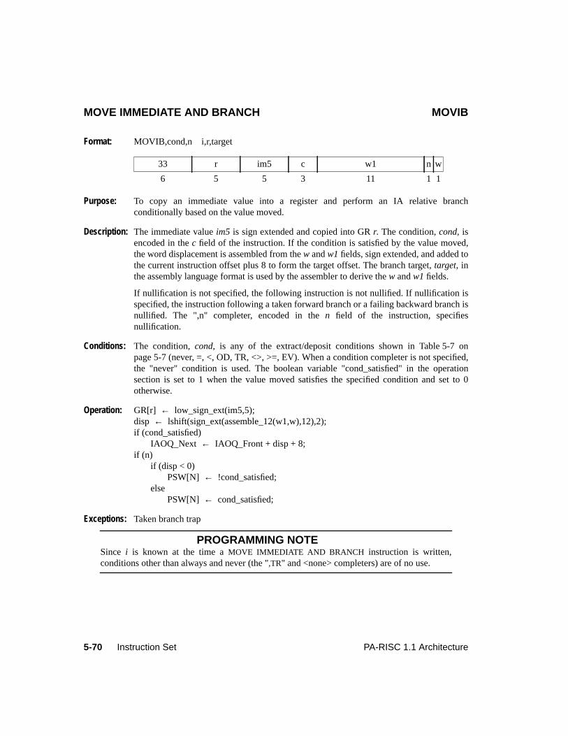
5-70 Instruction Set PA-RISC 1.1 Architecture
MOVE IMMEDIATE AND BRANCH MOVIB
Format: MOVIB,cond,n i,r,target
Purpose: To copy an immediate value into a register and perform an IA relative branchconditionally based on the value moved.
Description: The immediate valueim5 is sign extended and copied into GRr. The condition,cond, isencoded in thec field of the instruction. If the condition is satisfied by the value moved,the word displacement is assembled from thew andw1 fields, sign extended, and added tothe current instruction offset plus 8 to form the target offset. The branch target,target, inthe assembly language format is used by the assembler to derive thew andw1 fields.
If nullification is not specified, the following instruction is not nullified. If nullification isspecified, the instruction following a taken forward branch or a failing backward branch isnullified. The ",n" completer, encoded in then field of the instruction, specifiesnullification.
Conditions: The condition,cond, is any of the extract/deposit conditions shown in Table 5-7 onpage 5-7 (never, =, <, OD, TR, <>, >=, EV). When a condition completer is not specified,the "never" condition is used. The boolean variable "cond_satisfied" in the operationsection is set to 1 when the value moved satisfies the specified condition and set to 0otherwise.
Operation: GR[r] ← low_sign_ext(im5,5);disp ← lshift(sign_ext(assemble_12(w1,w),12),2);if (cond_satisfied)
IAOQ_Next ← IAOQ_Front + disp + 8;if (n)
if (disp < 0)PSW[N] ← !cond_satisfied;
elsePSW[N] ← cond_satisfied;
Exceptions: Taken branch trap
PROGRAMMING NOTESince i is known at the time aMOVE IMMEDIATE AND BRANCH instruction is written,conditions other than always and never (the ",TR" and <none> completers) are of no use.
33 r im5 c w1 n w
6 5 5 3 11 1 1
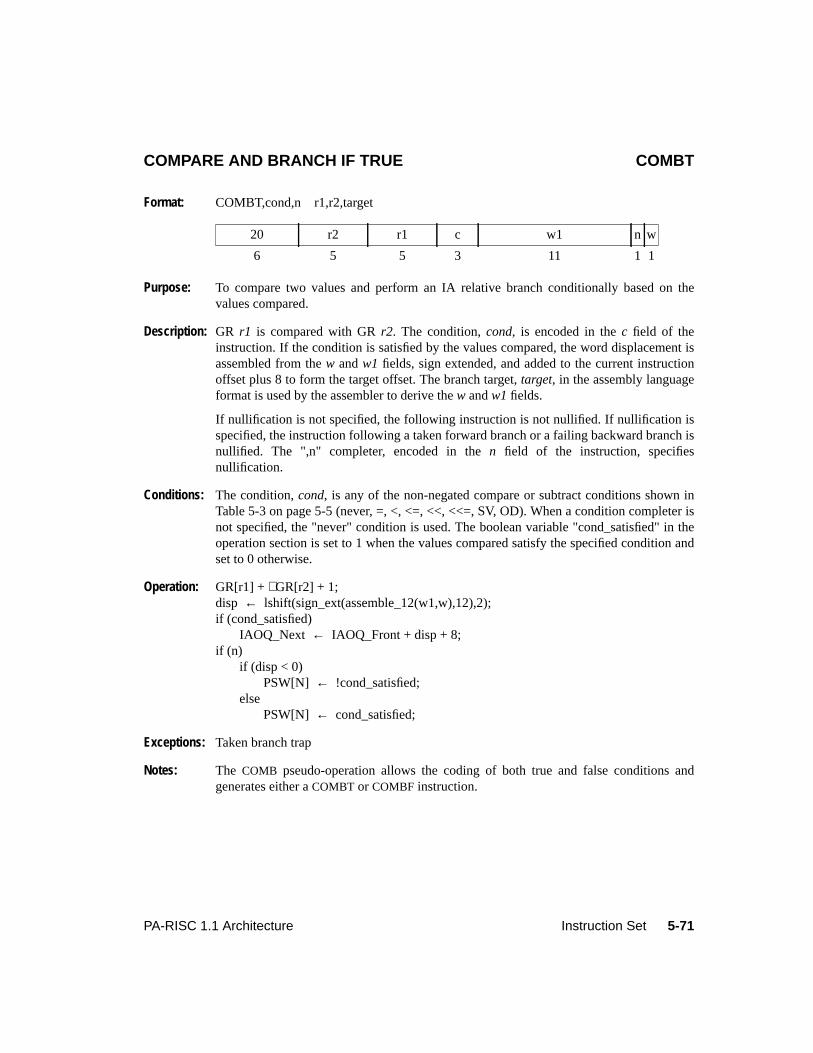
5-71PA-RISC 1.1 Architecture Instruction Set
COMPARE AND BRANCH IF TRUE COMBT
Format: COMBT,cond,n r1,r2,target
Purpose: To compare two values and perform an IA relative branch conditionally based on thevalues compared.
Description: GR r1 is compared with GRr2. The condition,cond, is encoded in thec field of theinstruction. If the condition is satisfied by the values compared, the word displacement isassembled from thew andw1 fields, sign extended, and added to the current instructionoffset plus 8 to form the target offset. The branch target,target, in the assembly languageformat is used by the assembler to derive thew andw1 fields.
If nullification is not specified, the following instruction is not nullified. If nullification isspecified, the instruction following a taken forward branch or a failing backward branch isnullified. The ",n" completer, encoded in then field of the instruction, specifiesnullification.
Conditions: The condition,cond, is any of the non-negated compare or subtract conditions shown inTable 5-3 on page 5-5 (never, =, <, <=, <<, <<=, SV, OD). When a condition completer isnot specified, the "never" condition is used. The boolean variable "cond_satisfied" in theoperation section is set to 1 when the values compared satisfy the specified condition andset to 0 otherwise.
Operation: GR[r1] + ∼GR[r2] + 1;disp ← lshift(sign_ext(assemble_12(w1,w),12),2);if (cond_satisfied)
IAOQ_Next ← IAOQ_Front + disp + 8;if (n)
if (disp < 0)PSW[N] ← !cond_satisfied;
elsePSW[N] ← cond_satisfied;
Exceptions: Taken branch trap
Notes: The COMB pseudo-operation allows the coding of both true and false conditions andgenerates either aCOMBT or COMBF instruction.
20 r2 r1 c w1 n w
6 5 5 3 11 1 1
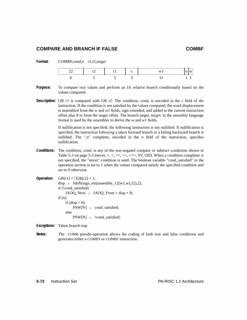
5-72 Instruction Set PA-RISC 1.1 Architecture
COMPARE AND BRANCH IF FALSE COMBF
Format: COMBF,cond,n r1,r2,target
Purpose: To compare two values and perform an IA relative branch conditionally based on thevalues compared.
Description: GR r1 is compared with GRr2. The condition,cond, is encoded in thec field of theinstruction. If the condition is not satisfied by the values compared, the word displacementis assembled from thew andw1 fields, sign extended, and added to the current instructionoffset plus 8 to form the target offset. The branch target,target, in the assembly languageformat is used by the assembler to derive thew andw1 fields.
If nullification is not specified, the following instruction is not nullified. If nullification isspecified, the instruction following a taken forward branch or a failing backward branch isnullified. The ",n" completer, encoded in then field of the instruction, specifiesnullification.
Conditions: The condition,cond, is any of the non-negated compare or subtract conditions shown inTable 5-3 on page 5-5 (never, =, <, <=, <<, <<=, SV, OD). When a condition completer isnot specified, the "never" condition is used. The boolean variable "cond_satisfied" in theoperation section is set to 1 when the values compared satisfy the specified condition andset to 0 otherwise.
Operation: GR[r1] + ∼GR[r2] + 1;disp ← lshift(sign_ext(assemble_12(w1,w),12),2);if (!cond_satisfied)
IAOQ_Next ← IAOQ_Front + disp + 8;if (n)
if (disp < 0)PSW[N] ← cond_satisfied;
elsePSW[N] ← !cond_satisfied;
Exceptions: Taken branch trap
Notes: The COMB pseudo-operation allows the coding of both true and false conditions andgenerates either aCOMBT or COMBF instruction.
22 r2 r1 c w1 n w
6 5 5 3 11 1 1
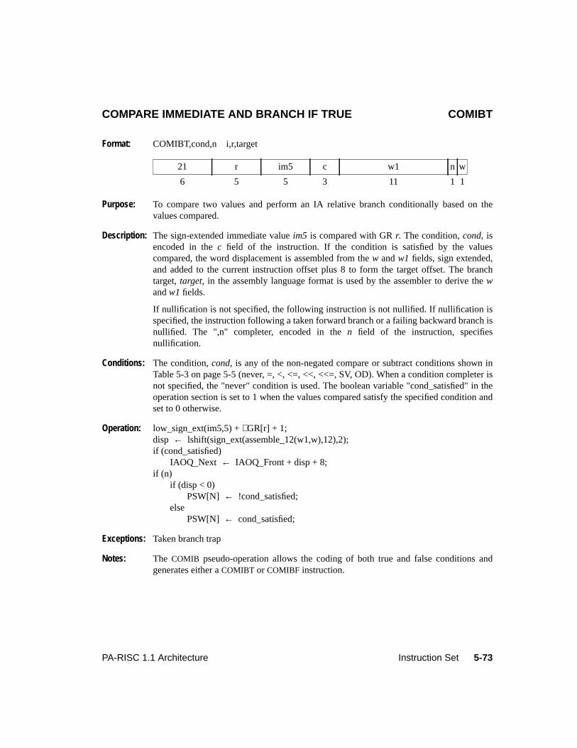
5-73PA-RISC 1.1 Architecture Instruction Set
COMPARE IMMEDIATE AND BRANCH IF TRUE COMIBT
Format: COMIBT,cond,n i,r,target
Purpose: To compare two values and perform an IA relative branch conditionally based on thevalues compared.
Description: The sign-extended immediate valueim5 is compared with GRr. The condition,cond, isencoded in thec field of the instruction. If the condition is satisfied by the valuescompared, the word displacement is assembled from thew andw1 fields, sign extended,and added to the current instruction offset plus 8 to form the target offset. The branchtarget,target, in the assembly language format is used by the assembler to derive thewandw1 fields.
If nullification is not specified, the following instruction is not nullified. If nullification isspecified, the instruction following a taken forward branch or a failing backward branch isnullified. The ",n" completer, encoded in then field of the instruction, specifiesnullification.
Conditions: The condition,cond, is any of the non-negated compare or subtract conditions shown inTable 5-3 on page 5-5 (never, =, <, <=, <<, <<=, SV, OD). When a condition completer isnot specified, the "never" condition is used. The boolean variable "cond_satisfied" in theoperation section is set to 1 when the values compared satisfy the specified condition andset to 0 otherwise.
Operation: low_sign_ext(im5,5) +∼GR[r] + 1;disp ← lshift(sign_ext(assemble_12(w1,w),12),2);if (cond_satisfied)
IAOQ_Next ← IAOQ_Front + disp + 8;if (n)
if (disp < 0)PSW[N] ← !cond_satisfied;
elsePSW[N] ← cond_satisfied;
Exceptions: Taken branch trap
Notes: The COMIB pseudo-operation allows the coding of both true and false conditions andgenerates either aCOMIBT or COMIBF instruction.
21 r im5 c w1 n w
6 5 5 3 11 1 1
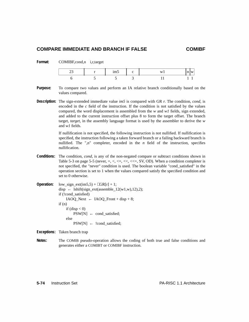
5-74 Instruction Set PA-RISC 1.1 Architecture
COMPARE IMMEDIATE AND BRANCH IF FALSE COMIBF
Format: COMIBF,cond,n i,r,target
Purpose: To compare two values and perform an IA relative branch conditionally based on thevalues compared.
Description: The sign-extended immediate valueim5 is compared with GRr. The condition,cond, isencoded in thec field of the instruction. If the condition is not satisfied by the valuescompared, the word displacement is assembled from thew andw1 fields, sign extended,and added to the current instruction offset plus 8 to form the target offset. The branchtarget,target, in the assembly language format is used by the assembler to derive thewandw1 fields.
If nullification is not specified, the following instruction is not nullified. If nullification isspecified, the instruction following a taken forward branch or a failing backward branch isnullified. The ",n" completer, encoded in then field of the instruction, specifiesnullification.
Conditions: The condition,cond, is any of the non-negated compare or subtract conditions shown inTable 5-3 on page 5-5 (never, =, <, <=, <<, <<=, SV, OD). When a condition completer isnot specified, the "never" condition is used. The boolean variable "cond_satisfied" in theoperation section is set to 1 when the values compared satisfy the specified condition andset to 0 otherwise.
Operation: low_sign_ext(im5,5) +∼GR[r] + 1;disp ← lshift(sign_ext(assemble_12(w1,w),12),2);if (!cond_satisfied)
IAOQ_Next ← IAOQ_Front + disp + 8;if (n)
if (disp < 0)PSW[N] ← cond_satisfied;
elsePSW[N] ← !cond_satisfied;
Exceptions: Taken branch trap
Notes: The COMIB pseudo-operation allows the coding of both true and false conditions andgenerates either aCOMIBT or COMIBF instruction.
23 r im5 c w1 n w
6 5 5 3 11 1 1
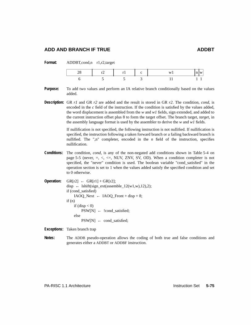
5-75PA-RISC 1.1 Architecture Instruction Set
ADD AND BRANCH IF TRUE ADDBT
Format: ADDBT,cond,n r1,r2,target
Purpose: To add two values and perform an IA relative branch conditionally based on the valuesadded.
Description: GR r1 and GRr2 are added and the result is stored in GRr2. The condition,cond, isencoded in thec field of the instruction. If the condition is satisfied by the values added,the word displacement is assembled from thew andw1 fields, sign extended, and added tothe current instruction offset plus 8 to form the target offset. The branch target,target, inthe assembly language format is used by the assembler to derive thew andw1 fields.
If nullification is not specified, the following instruction is not nullified. If nullification isspecified, the instruction following a taken forward branch or a failing backward branch isnullified. The ",n" completer, encoded in then field of the instruction, specifiesnullification.
Conditions: The condition,cond, is any of the non-negated add conditions shown in Table 5-4 onpage 5-5 (never, =, <, <=, NUV, ZNV, SV, OD). When a condition completer is notspecified, the "never" condition is used. The boolean variable "cond_satisfied" in theoperation section is set to 1 when the values added satisfy the specified condition and setto 0 otherwise.
Operation: GR[r2] ← GR[r1] + GR[r2];disp ← lshift(sign_ext(assemble_12(w1,w),12),2);if (cond_satisfied)
IAOQ_Next ← IAOQ_Front + disp + 8;if (n)
if (disp < 0)PSW[N] ← !cond_satisfied;
elsePSW[N] ← cond_satisfied;
Exceptions: Taken branch trap
Notes: The ADDB pseudo-operation allows the coding of both true and false conditions andgenerates either aADDBT or ADDBF instruction.
28 r2 r1 c w1 n w
6 5 5 3 11 1 1
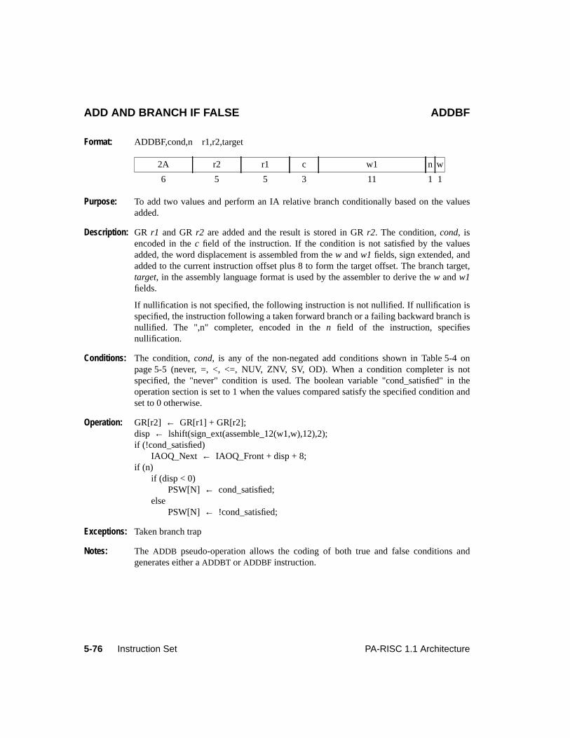
5-76 Instruction Set PA-RISC 1.1 Architecture
ADD AND BRANCH IF FALSE ADDBF
Format: ADDBF,cond,n r1,r2,target
Purpose: To add two values and perform an IA relative branch conditionally based on the valuesadded.
Description: GR r1 and GRr2 are added and the result is stored in GRr2. The condition,cond, isencoded in thec field of the instruction. If the condition is not satisfied by the valuesadded, the word displacement is assembled from thew andw1 fields, sign extended, andadded to the current instruction offset plus 8 to form the target offset. The branch target,target, in the assembly language format is used by the assembler to derive thew andw1fields.
If nullification is not specified, the following instruction is not nullified. If nullification isspecified, the instruction following a taken forward branch or a failing backward branch isnullified. The ",n" completer, encoded in then field of the instruction, specifiesnullification.
Conditions: The condition,cond, is any of the non-negated add conditions shown in Table 5-4 onpage 5-5 (never, =, <, <=, NUV, ZNV, SV, OD). When a condition completer is notspecified, the "never" condition is used. The boolean variable "cond_satisfied" in theoperation section is set to 1 when the values compared satisfy the specified condition andset to 0 otherwise.
Operation: GR[r2] ← GR[r1] + GR[r2];disp ← lshift(sign_ext(assemble_12(w1,w),12),2);if (!cond_satisfied)
IAOQ_Next ← IAOQ_Front + disp + 8;if (n)
if (disp < 0)PSW[N] ← cond_satisfied;
elsePSW[N] ← !cond_satisfied;
Exceptions: Taken branch trap
Notes: The ADDB pseudo-operation allows the coding of both true and false conditions andgenerates either aADDBT or ADDBF instruction.
2A r2 r1 c w1 n w
6 5 5 3 11 1 1
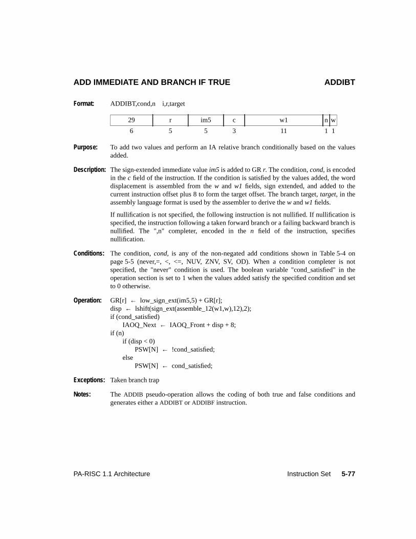
5-77PA-RISC 1.1 Architecture Instruction Set
ADD IMMEDIATE AND BRANCH IF TRUE ADDIBT
Format: ADDIBT,cond,n i,r,target
Purpose: To add two values and perform an IA relative branch conditionally based on the valuesadded.
Description: The sign-extended immediate valueim5 is added to GRr. The condition,cond, is encodedin thec field of the instruction. If the condition is satisfied by the values added, the worddisplacement is assembled from thew and w1 fields, sign extended, and added to thecurrent instruction offset plus 8 to form the target offset. The branch target,target, in theassembly language format is used by the assembler to derive thew andw1 fields.
If nullification is not specified, the following instruction is not nullified. If nullification isspecified, the instruction following a taken forward branch or a failing backward branch isnullified. The ",n" completer, encoded in then field of the instruction, specifiesnullification.
Conditions: The condition,cond, is any of the non-negated add conditions shown in Table 5-4 onpage 5-5 (never,=, <, <=, NUV, ZNV, SV, OD). When a condition completer is notspecified, the "never" condition is used. The boolean variable "cond_satisfied" in theoperation section is set to 1 when the values added satisfy the specified condition and setto 0 otherwise.
Operation: GR[r] ← low_sign_ext(im5,5) + GR[r];disp ← lshift(sign_ext(assemble_12(w1,w),12),2);if (cond_satisfied)
IAOQ_Next ← IAOQ_Front + disp + 8;if (n)
if (disp < 0)PSW[N] ← !cond_satisfied;
elsePSW[N] ← cond_satisfied;
Exceptions: Taken branch trap
Notes: The ADDIB pseudo-operation allows the coding of both true and false conditions andgenerates either aADDIBT or ADDIBF instruction.
29 r im5 c w1 n w
6 5 5 3 11 1 1
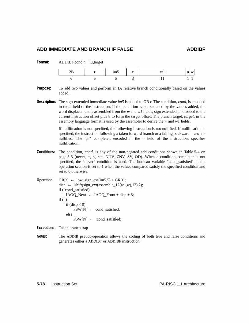
5-78 Instruction Set PA-RISC 1.1 Architecture
ADD IMMEDIATE AND BRANCH IF FALSE ADDIBF
Format: ADDIBF,cond,n i,r,target
Purpose: To add two values and perform an IA relative branch conditionally based on the valuesadded.
Description: The sign-extended immediate valueim5 is added to GRr. The condition,cond, is encodedin thec field of the instruction. If the condition is not satisfied by the values added, theword displacement is assembled from thew andw1 fields, sign extended, and added to thecurrent instruction offset plus 8 to form the target offset. The branch target,target, in theassembly language format is used by the assembler to derive thew andw1 fields.
If nullification is not specified, the following instruction is not nullified. If nullification isspecified, the instruction following a taken forward branch or a failing backward branch isnullified. The ",n" completer, encoded in then field of the instruction, specifiesnullification.
Conditions: The condition,cond, is any of the non-negated add conditions shown in Table 5-4 onpage 5-5 (never, =, <, <=, NUV, ZNV, SV, OD). When a condition completer is notspecified, the "never" condition is used. The boolean variable "cond_satisfied" in theoperation section is set to 1 when the values compared satisfy the specified condition andset to 0 otherwise.
Operation: GR[r] ← low_sign_ext(im5,5) + GR[r];disp ← lshift(sign_ext(assemble_12(w1,w),12),2);if (!cond_satisfied)
IAOQ_Next ← IAOQ_Front + disp + 8;if (n)
if (disp < 0)PSW[N] ← cond_satisfied;
elsePSW[N] ← !cond_satisfied;
Exceptions: Taken branch trap
Notes: The ADDIB pseudo-operation allows the coding of both true and false conditions andgenerates either aADDIBT or ADDIBF instruction.
2B r im5 c w1 n w
6 5 5 3 11 1 1
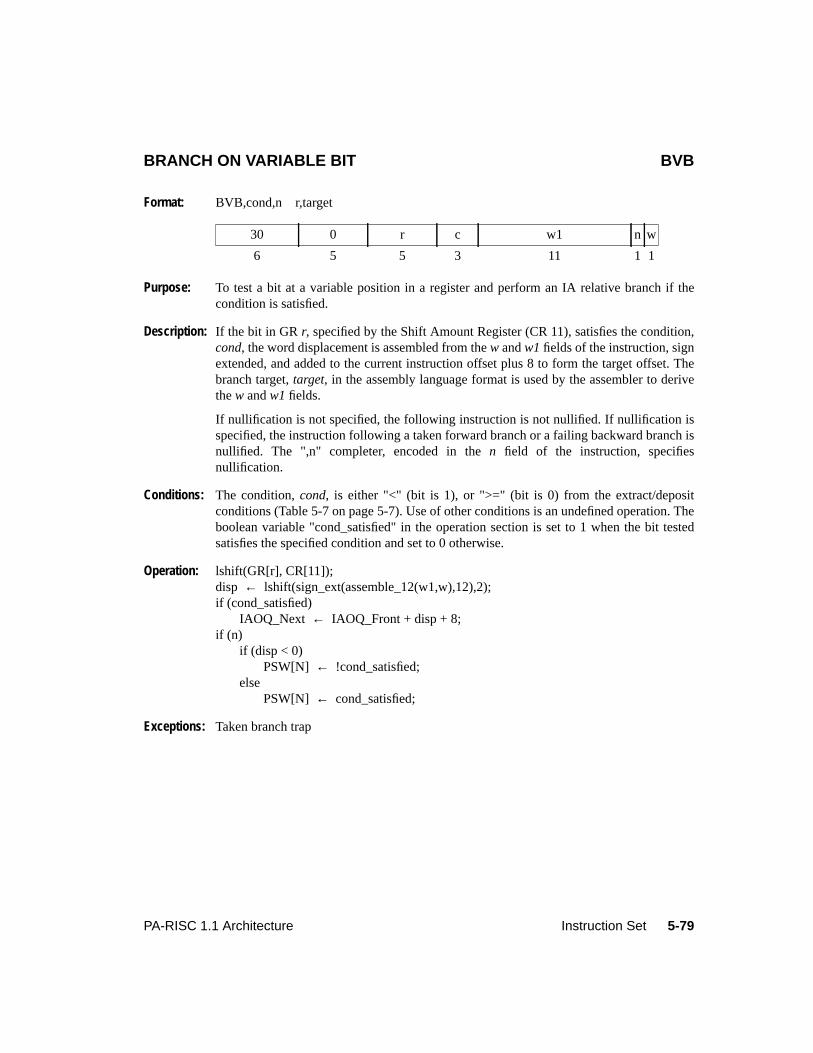
5-79PA-RISC 1.1 Architecture Instruction Set
BRANCH ON VARIABLE BIT BVB
Format: BVB,cond,n r,target
Purpose: To test a bit at a variable position in a register and perform an IA relative branch if thecondition is satisfied.
Description: If the bit in GRr, specified by the Shift Amount Register (CR 11), satisfies the condition,cond, the word displacement is assembled from thew andw1 fields of the instruction, signextended, and added to the current instruction offset plus 8 to form the target offset. Thebranch target,target, in the assembly language format is used by the assembler to derivethew andw1 fields.
If nullification is not specified, the following instruction is not nullified. If nullification isspecified, the instruction following a taken forward branch or a failing backward branch isnullified. The ",n" completer, encoded in then field of the instruction, specifiesnullification.
Conditions: The condition,cond, is either "<" (bit is 1), or ">=" (bit is 0) from the extract/depositconditions (Table 5-7 on page 5-7). Use of other conditions is an undefined operation. Theboolean variable "cond_satisfied" in the operation section is set to 1 when the bit testedsatisfies the specified condition and set to 0 otherwise.
Operation: lshift(GR[r], CR[11]);disp ← lshift(sign_ext(assemble_12(w1,w),12),2);if (cond_satisfied)
IAOQ_Next ← IAOQ_Front + disp + 8;if (n)
if (disp < 0)PSW[N] ← !cond_satisfied;
elsePSW[N] ← cond_satisfied;
Exceptions: Taken branch trap
30 0 r c w1 n w
6 5 5 3 11 1 1
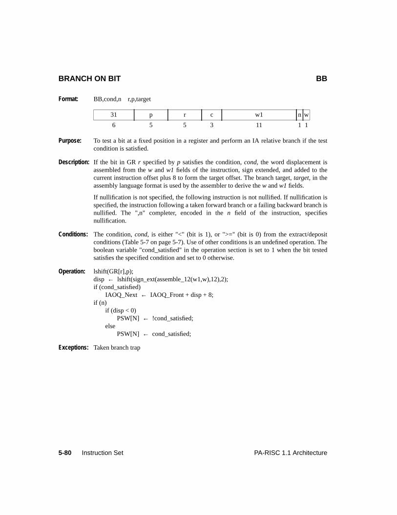
5-80 Instruction Set PA-RISC 1.1 Architecture
BRANCH ON BIT BB
Format: BB,cond,n r,p,target
Purpose: To test a bit at a fixed position in a register and perform an IA relative branch if the testcondition is satisfied.
Description: If the bit in GRr specified byp satisfies the condition,cond, the word displacement isassembled from thew andw1 fields of the instruction, sign extended, and added to thecurrent instruction offset plus 8 to form the target offset. The branch target,target, in theassembly language format is used by the assembler to derive thew andw1 fields.
If nullification is not specified, the following instruction is not nullified. If nullification isspecified, the instruction following a taken forward branch or a failing backward branch isnullified. The ",n" completer, encoded in then field of the instruction, specifiesnullification.
Conditions: The condition,cond, is either "<" (bit is 1), or ">=" (bit is 0) from the extract/depositconditions (Table 5-7 on page 5-7). Use of other conditions is an undefined operation. Theboolean variable "cond_satisfied" in the operation section is set to 1 when the bit testedsatisfies the specified condition and set to 0 otherwise.
Operation: lshift(GR[r],p);disp ← lshift(sign_ext(assemble_12(w1,w),12),2);if (cond_satisfied)
IAOQ_Next ← IAOQ_Front + disp + 8;if (n)
if (disp < 0)PSW[N] ← !cond_satisfied;
elsePSW[N] ← cond_satisfied;
Exceptions: Taken branch trap
31 p r c w1 n w
6 5 5 3 11 1 1
5-81PA-RISC 1.1 Architecture Instruction Set
5Instruction Set
Computation InstructionsComputation instructions are comprised of the arithmetic, logical, shift, extract, and depositinstructions. The two 5-bit fields following the 6-bit opcode field could consist of the followingcombinations:
1. Two source registers.
2. A source register and a target register.
3. A source register and a 5-bit immediate.
4. A target register and a 5-bit immediate.
The three register arithmetic and logical instructions take two source arguments from two generalregisters. These source registers are specified by the two 5-bit fields following the opcode specifier. Therightmost 5-bit field specifies the target register.
Some of the computation instructions have a signed immediate argument which is either five bits oreleven bits in length. The 5-bit immediate is encoded in the second 5-bit field following the opcode fieldand the target specifier in the first 5-bit field following the opcode field. The 11-bit immediate isencoded in the rightmost 11-bit field, and the target specifier in the second 5-bit field following theopcode specifier.
Any computation instruction may nullify the instruction following, given the correct conditions. Mostcomputation instructions encode the condition completers in the 3-bitc-field and 1-bitf-field of theinstructions. The exceptions are the instructions that use the extract/deposit conditions. Thecomputation instructions that use the extract/deposit conditions encode the condition completers in onlythe 3-bitc-field. The condition completers are used to determine if the instruction following is nullified,based on the contents of the source operands and the operation performed.
Three-Register Arithmetic and Logical InstructionsThese instructions perform arithmetic and logical operations between two operands in registers andstore the result into a register. Each arithmetic/logical instruction also specifies the conditionaloccurrence of either a skip or a trap, based on its opcode and the condition field. Not all options areavailable on every instruction. Only those operations and options considered useful are defined.
Immediate Arithmetic OperationsThe immediate arithmetic instructions operate between a sign-extended 11-bit immediate and thecontents of a register. The result is stored in a register. Immediate operations may optionally trap onoverflow. In addition, immediate adds may trap on a specific condition.
The 11-bit immediate field has the sign bit in the rightmost position, but the other 10 bits are in the usualorder. The 1-bit opcode extension field determines whether overflow causes a trap.
Shift Double, Extract, and Deposit InstructionsThe double shift operations allow for a concatenation of two registers followed by a shift of 0 to 31 bit
5-82 Instruction Set PA-RISC 1.1 Architecture
positions. The rightmost 32 bits are stored in a general register. Depending on the choice of the sourceregisters, this operation allows the user to perform right or left shifts, rotates, bit field extractions whenthe bit field crosses word boundaries, unaligned byte moves, and so on.
Extract instructions take a field from a source register and insert it right-justified into the target register.This field is either zero extended or sign extended. This way, the extract instructions support bothlogical and arithmetic shift operations.
Deposits either set the target to zero or leave it unchanged (merge operation). The deposit instructionsthen take a right-justified field from a source and deposit it into any portion of the target. The source canbe either a register or a 5-bit signed immediate value. The 5-bit immediate field has the sign bit in therightmost position, but the other 4 bits are in the usual order. Deposit instructions support left shiftoperations and simple multiplication by powers of two.
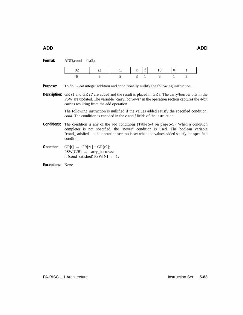
5-83PA-RISC 1.1 Architecture Instruction Set
ADD ADD
Format: ADD,cond r1,r2,t
Purpose: To do 32-bit integer addition and conditionally nullify the following instruction.
Description: GR r1 and GRr2 are added and the result is placed in GRt. The carry/borrow bits in thePSW are updated. The variable "carry_borrows" in the operation section captures the 4-bitcarries resulting from the add operation.
The following instruction is nullified if the values added satisfy the specified condition,cond. The condition is encoded in thec andf fields of the instruction.
Conditions: The condition is any of the add conditions (Table 5-4 on page 5-5). When a conditioncompleter is not specified, the "never" condition is used. The boolean variable"cond_satisfied" in the operation section is set when the values added satisfy the specifiedcondition.
Operation: GR[t] ← GR[r1] + GR[r2];PSW[C/B] ← carry_borrows;if (cond_satisfied) PSW[N]← 1;
Exceptions: None
02 r2 r1 c f 18 0 t
6 5 5 3 1 6 1 5
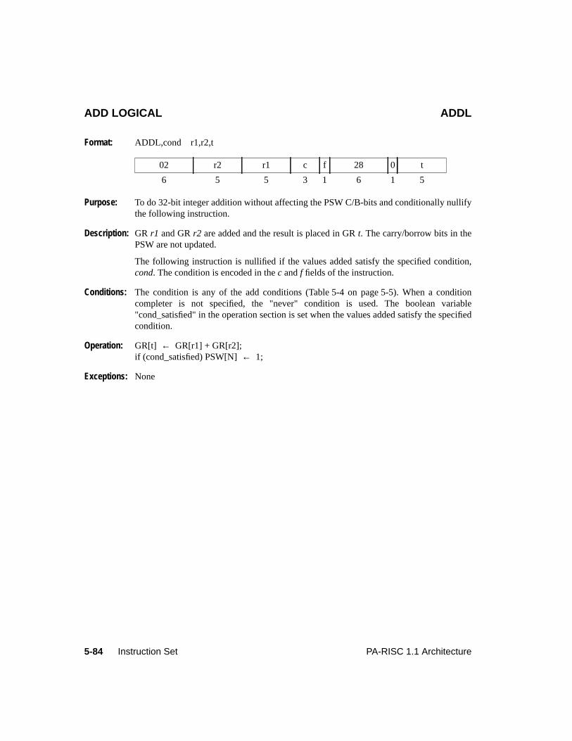
5-84 Instruction Set PA-RISC 1.1 Architecture
ADD LOGICAL ADDL
Format: ADDL,cond r1,r2,t
Purpose: To do 32-bit integer addition without affecting the PSW C/B-bits and conditionally nullifythe following instruction.
Description: GR r1 and GRr2 are added and the result is placed in GRt. The carry/borrow bits in thePSW are not updated.
The following instruction is nullified if the values added satisfy the specified condition,cond. The condition is encoded in thec andf fields of the instruction.
Conditions: The condition is any of the add conditions (Table 5-4 on page 5-5). When a conditioncompleter is not specified, the "never" condition is used. The boolean variable"cond_satisfied" in the operation section is set when the values added satisfy the specifiedcondition.
Operation: GR[t] ← GR[r1] + GR[r2];if (cond_satisfied) PSW[N]← 1;
Exceptions: None
02 r2 r1 c f 28 0 t
6 5 5 3 1 6 1 5
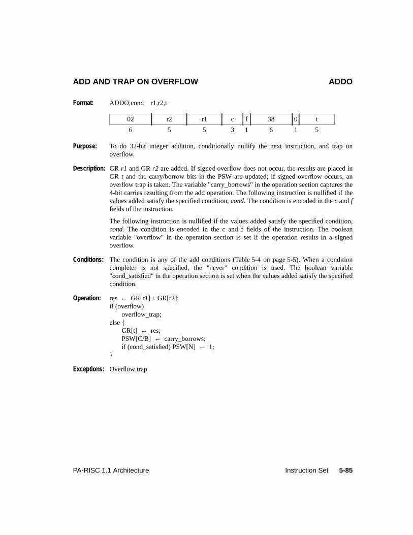
5-85PA-RISC 1.1 Architecture Instruction Set
ADD AND TRAP ON OVERFLOW ADDO
Format: ADDO,cond r1,r2,t
Purpose: To do 32-bit integer addition, conditionally nullify the next instruction, and trap onoverflow.
Description: GR r1 and GRr2 are added. If signed overflow does not occur, the results are placed inGR t and the carry/borrow bits in the PSW are updated; if signed overflow occurs, anoverflow trap is taken. The variable "carry_borrows" in the operation section captures the4-bit carries resulting from the add operation. The following instruction is nullified if thevalues added satisfy the specified condition,cond. The condition is encoded in thec andffields of the instruction.
The following instruction is nullified if the values added satisfy the specified condition,cond. The condition is encoded in the c and f fields of the instruction. The booleanvariable "overflow" in the operation section is set if the operation results in a signedoverflow.
Conditions: The condition is any of the add conditions (Table 5-4 on page 5-5). When a conditioncompleter is not specified, the "never" condition is used. The boolean variable"cond_satisfied" in the operation section is set when the values added satisfy the specifiedcondition.
Operation: res ← GR[r1] + GR[r2];if (overflow)
overflow_trap;else {
GR[t] ← res;PSW[C/B] ← carry_borrows;if (cond_satisfied) PSW[N]← 1;
}
Exceptions: Overflow trap
02 r2 r1 c f 38 0 t
6 5 5 3 1 6 1 5
5-86 Instruction Set PA-RISC 1.1 Architecture
ADD WITH CARRY ADDC
Format: ADDC,cond r1,r2,t
Purpose: To do 32-bit integer addition with carry and conditionally nullify the followinginstruction.
Description: GR r1 and GRr2 are added with the leftmost carry/borrow bit from the PSW and theresult is placed in GRt. The carry/borrow bits in the PSW are updated. The variable"carry_borrows" in the operation section captures the 4-bit carries resulting from the addoperation.
The following instruction is nullified if the values added satisfy the specified condition,cond. The condition is encoded in thec andf fields of the instruction.
Conditions: The condition is any of the add conditions (Table 5-4 on page 5-5). When a conditioncompleter is not specified, the "never" condition is used. The boolean variable"cond_satisfied" in the operation section is set when the values added satisfy the specifiedcondition.
Operation: GR[t] ← GR[r1] + GR[r2] + PSW[C/B]{0};PSW[C/B] ← carry_borrows;if (cond_satisfied) PSW[N]← 1;
Exceptions: None
02 r2 r1 c f 1C 0 t
6 5 5 3 1 6 1 5
5-87PA-RISC 1.1 Architecture Instruction Set
ADD WITH CARRY AND TRAP ON OVERFLOW ADDCO
Format: ADDCO,cond r1,r2,t
Purpose: To do 32-bit integer addition with carry, conditionally nullify the following instruction,and trap on overflow.
Description: GR r1 and GRr2 are added with the leftmost carry/borrow bit from the PSW. If signedoverflow does not occur, the result is placed in GRt; if signed overflow occurs, anoverflow trap is taken instead. The carry/borrow bits in the PSW are updated. The variable"carry_borrows" in the operation section captures the 4-bit carries resulting from the addoperation.
The following instruction is nullified if the values added satisfy the specified condition,cond. The condition is encoded in thec andf fields of the instruction. The boolean variable"overflow" in the operation section is set if the operation results in a signed overflow.
Conditions: The condition is any of the add conditions (Table 5-4 on page 5-5). When a conditioncompleter is not specified, the "never" condition is used. The boolean variable"cond_satisfied" in the operation section is set when the values added satisfy the specifiedcondition.
Operation: res ← GR[r1] + GR[r2] + PSW[C/B]{0};if (overflow)
overflow_trap;else {
GR[t] ← res;PSW[C/B] ← carry_borrows;if (cond_satisfied) PSW[N]← 1;
}
Exceptions: Overflow trap
02 r2 r1 c f 3C 0 t
6 5 5 3 1 6 1 5
5-88 Instruction Set PA-RISC 1.1 Architecture
SHIFT ONE AND ADD SH1ADD
Format: SH1ADD,cond r1,r2,t
Purpose: To provide a primitive operation for multiplication.
Description: GR r1 is shifted left one bit position and added to GRr2. The result is placed in GRt andthe carry/borrow bits in the PSW are updated. The variable "carry_borrows" in theoperation section captures the 4-bit carries resulting from the add operation. The followinginstruction is nullified if the values added satisfy the specified condition,cond. Thecondition is encoded in thec andf fields of the instruction.
For this instruction, signed overflow condition means that either the bit shifted out differsfrom the leftmost bit following the shift or an ordinary signed overflow occurred duringthe addition. Unsigned overflow means that the bit shifted out is 1 or an ordinary unsignedoverflow occurred during the addition. The conditions take on special interpretations sincethe shift operation participates in overflow determination.
Conditions: The condition is any of the add conditions (Table 5-4 on page 5-5). When a conditioncompleter is not specified, the "never" condition is used. The boolean variable"cond_satisfied" in the operation section is set when the values added satisfy the specifiedcondition.
Operation: GR[t] ← lshift(GR[r1], 1) + GR[r2];PSW[C/B] ← carry_borrows;if (cond_satisfied) PSW[N]← 1;
Exceptions: None
02 r2 r1 c f 19 0 t
6 5 5 3 1 6 1 5
5-89PA-RISC 1.1 Architecture Instruction Set
SHIFT ONE AND ADD LOGICAL SH1ADDL
Format: SH1ADDL,cond r1,r2,t
Purpose: To provide a primitive operation for multiplication without affecting the carry/borrow bits.
Description: GR r1 is shifted left one bit position and added to GRr2. The result is placed in GRt. Thecarry/borrow bits in the PSW are not affected. The following instruction is nullified if thevalues added satisfy the specified condition,cond. The condition is encoded in thec andffields of the instruction.
For this instruction, signed overflow condition means that either the bit shifted out differsfrom the leftmost bit following the shift or an ordinary signed overflow occurred duringthe addition. Unsigned overflow means that the bit shifted out is 1 or that an ordinaryunsigned overflow occurred during the addition. The conditions take on specialinterpretations since the shift operation participates in overflow determination.
Conditions: The condition is any of the add conditions (Table 5-4 on page 5-5). When a conditioncompleter is not specified, the "never" condition is used. The boolean variable"cond_satisfied" in the operation section is set when the values added satisfy the specifiedcondition.
Operation: GR[t] ← lshift(GR[r1], 1) + GR[r2];if (cond_satisfied) PSW[N]← 1;
Exceptions: None
02 r2 r1 c f 29 0 t
6 5 5 3 1 6 1 5
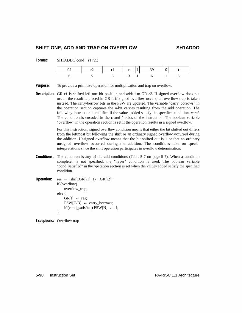
5-90 Instruction Set PA-RISC 1.1 Architecture
SHIFT ONE, ADD AND TRAP ON OVERFLOW SH1ADDO
Format: SH1ADDO,cond r1,r2,t
Purpose: To provide a primitive operation for multiplication and trap on overflow.
Description: GR r1 is shifted left one bit position and added to GRr2. If signed overflow does notoccur, the result is placed in GRt; if signed overflow occurs, an overflow trap is takeninstead. The carry/borrow bits in the PSW are updated. The variable "carry_borrows" inthe operation section captures the 4-bit carries resulting from the add operation. Thefollowing instruction is nullified if the values added satisfy the specified condition,cond.The condition is encoded in thec and f fields of the instruction. The boolean variable"overflow" in the operation section is set if the operation results in a signed overflow.
For this instruction, signed overflow condition means that either the bit shifted out differsfrom the leftmost bit following the shift or an ordinary signed overflow occurred duringthe addition. Unsigned overflow means that the bit shifted out is 1 or that an ordinaryunsigned overflow occurred during the addition. The conditions take on specialinterpretations since the shift operation participates in overflow determination.
Conditions: The condition is any of the add conditions (Table 5-7 on page 5-7). When a conditioncompleter is not specified, the "never" condition is used. The boolean variable"cond_satisfied" in the operation section is set when the values added satisfy the specifiedcondition.
Operation: res ← lshift(GR[r1], 1) + GR[r2];if (overflow)
overflow_trap;else {
GR[t] ← res;PSW[C/B] ← carry_borrows;if (cond_satisfied) PSW[N]← 1;
}
Exceptions: Overflow trap
02 r2 r1 c f 39 0 t
6 5 5 3 1 6 1 5
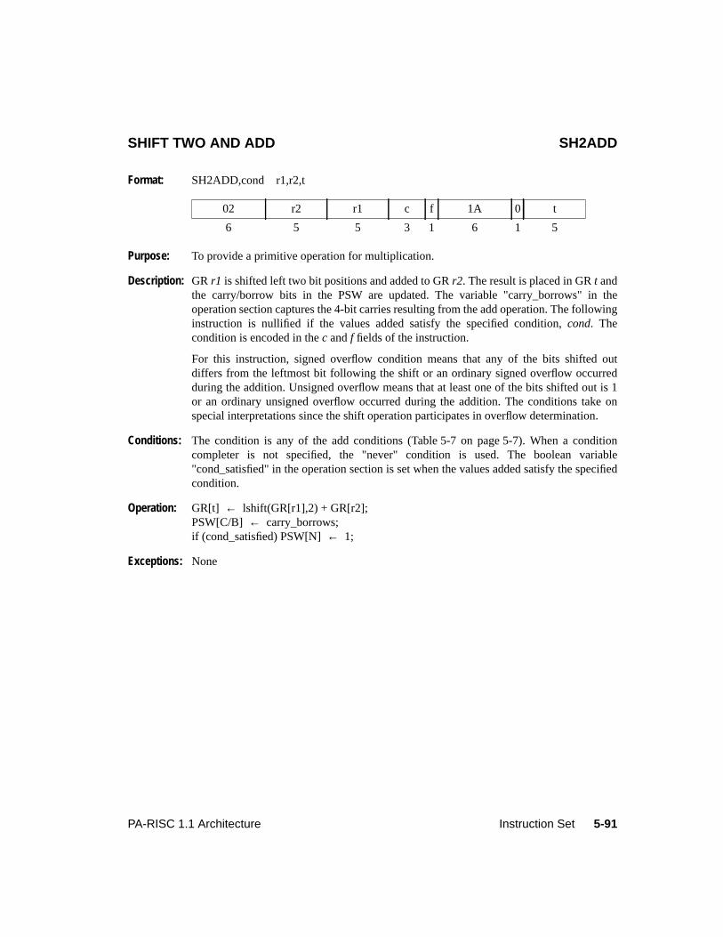
5-91PA-RISC 1.1 Architecture Instruction Set
SHIFT TWO AND ADD SH2ADD
Format: SH2ADD,cond r1,r2,t
Purpose: To provide a primitive operation for multiplication.
Description: GR r1 is shifted left two bit positions and added to GRr2. The result is placed in GRt andthe carry/borrow bits in the PSW are updated. The variable "carry_borrows" in theoperation section captures the 4-bit carries resulting from the add operation. The followinginstruction is nullified if the values added satisfy the specified condition,cond. Thecondition is encoded in thec andf fields of the instruction.
For this instruction, signed overflow condition means that any of the bits shifted outdiffers from the leftmost bit following the shift or an ordinary signed overflow occurredduring the addition. Unsigned overflow means that at least one of the bits shifted out is 1or an ordinary unsigned overflow occurred during the addition. The conditions take onspecial interpretations since the shift operation participates in overflow determination.
Conditions: The condition is any of the add conditions (Table 5-7 on page 5-7). When a conditioncompleter is not specified, the "never" condition is used. The boolean variable"cond_satisfied" in the operation section is set when the values added satisfy the specifiedcondition.
Operation: GR[t] ← lshift(GR[r1],2) + GR[r2];PSW[C/B] ← carry_borrows;if (cond_satisfied) PSW[N]← 1;
Exceptions: None
02 r2 r1 c f 1A 0 t
6 5 5 3 1 6 1 5
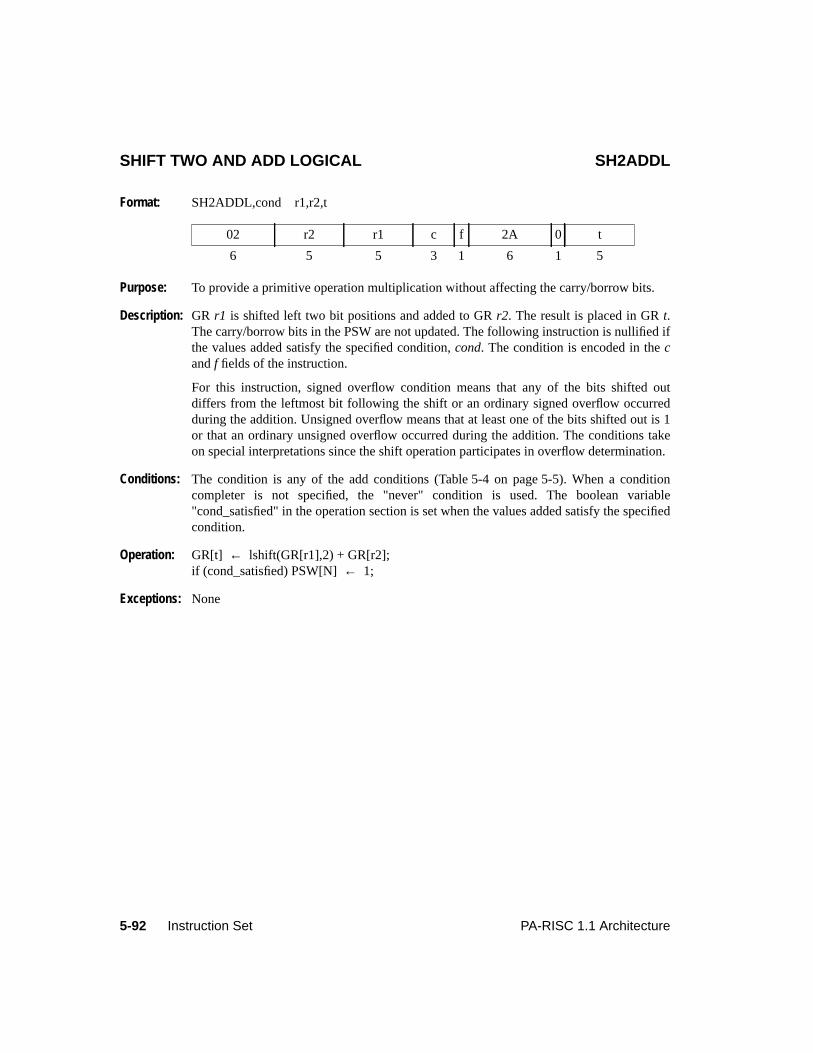
5-92 Instruction Set PA-RISC 1.1 Architecture
SHIFT TWO AND ADD LOGICAL SH2ADDL
Format: SH2ADDL,cond r1,r2,t
Purpose: To provide a primitive operation multiplication without affecting the carry/borrow bits.
Description: GR r1 is shifted left two bit positions and added to GRr2. The result is placed in GRt.The carry/borrow bits in the PSW are not updated. The following instruction is nullified ifthe values added satisfy the specified condition,cond. The condition is encoded in thecandf fields of the instruction.
For this instruction, signed overflow condition means that any of the bits shifted outdiffers from the leftmost bit following the shift or an ordinary signed overflow occurredduring the addition. Unsigned overflow means that at least one of the bits shifted out is 1or that an ordinary unsigned overflow occurred during the addition. The conditions takeon special interpretations since the shift operation participates in overflow determination.
Conditions: The condition is any of the add conditions (Table 5-4 on page 5-5). When a conditioncompleter is not specified, the "never" condition is used. The boolean variable"cond_satisfied" in the operation section is set when the values added satisfy the specifiedcondition.
Operation: GR[t] ← lshift(GR[r1],2) + GR[r2];if (cond_satisfied) PSW[N]← 1;
Exceptions: None
02 r2 r1 c f 2A 0 t
6 5 5 3 1 6 1 5
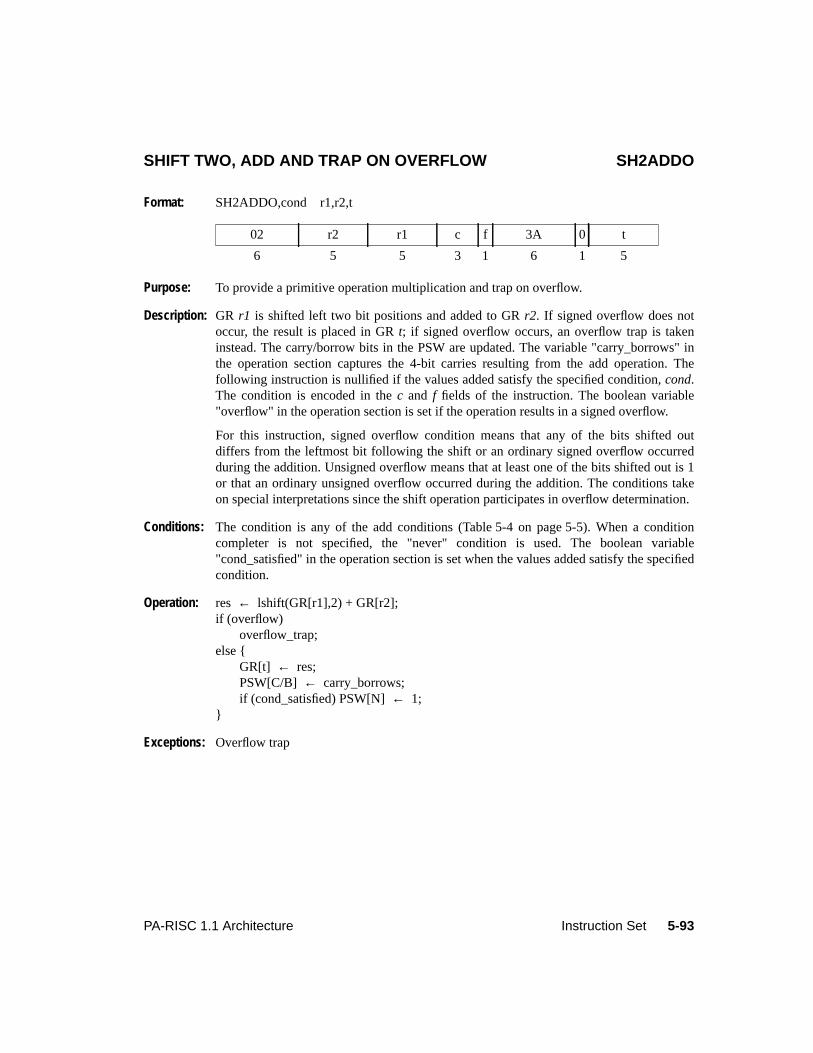
5-93PA-RISC 1.1 Architecture Instruction Set
SHIFT TWO, ADD AND TRAP ON OVERFLOW SH2ADDO
Format: SH2ADDO,cond r1,r2,t
Purpose: To provide a primitive operation multiplication and trap on overflow.
Description: GR r1 is shifted left two bit positions and added to GRr2. If signed overflow does notoccur, the result is placed in GRt; if signed overflow occurs, an overflow trap is takeninstead. The carry/borrow bits in the PSW are updated. The variable "carry_borrows" inthe operation section captures the 4-bit carries resulting from the add operation. Thefollowing instruction is nullified if the values added satisfy the specified condition,cond.The condition is encoded in thec and f fields of the instruction. The boolean variable"overflow" in the operation section is set if the operation results in a signed overflow.
For this instruction, signed overflow condition means that any of the bits shifted outdiffers from the leftmost bit following the shift or an ordinary signed overflow occurredduring the addition. Unsigned overflow means that at least one of the bits shifted out is 1or that an ordinary unsigned overflow occurred during the addition. The conditions takeon special interpretations since the shift operation participates in overflow determination.
Conditions: The condition is any of the add conditions (Table 5-4 on page 5-5). When a conditioncompleter is not specified, the "never" condition is used. The boolean variable"cond_satisfied" in the operation section is set when the values added satisfy the specifiedcondition.
Operation: res ← lshift(GR[r1],2) + GR[r2];if (overflow)
overflow_trap;else {
GR[t] ← res;PSW[C/B] ← carry_borrows;if (cond_satisfied) PSW[N]← 1;
}
Exceptions: Overflow trap
02 r2 r1 c f 3A 0 t
6 5 5 3 1 6 1 5
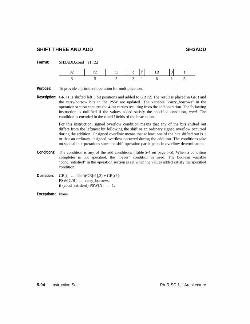
5-94 Instruction Set PA-RISC 1.1 Architecture
SHIFT THREE AND ADD SH3ADD
Format: SH3ADD,cond r1,r2,t
Purpose: To provide a primitive operation for multiplication.
Description: GR r1 is shifted left 3 bit positions and added to GRr2. The result is placed in GRt andthe carry/borrow bits in the PSW are updated. The variable "carry_borrows" in theoperation section captures the 4-bit carries resulting from the add operation. The followinginstruction is nullified if the values added satisfy the specified condition,cond. Thecondition is encoded in thec andf fields of the instruction.
For this instruction, signed overflow condition means that any of the bits shifted outdiffers from the leftmost bit following the shift or an ordinary signed overflow occurredduring the addition. Unsigned overflow means that at least one of the bits shifted out is 1or that an ordinary unsigned overflow occurred during the addition. The conditions takeon special interpretations since the shift operation participates in overflow determination.
Conditions: The condition is any of the add conditions (Table 5-4 on page 5-5). When a conditioncompleter is not specified, the "never" condition is used. The boolean variable"cond_satisfied" in the operation section is set when the values added satisfy the specifiedcondition.
Operation: GR[t] ← lshift(GR[r1],3) + GR[r2];PSW[C/B] ← carry_borrows;if (cond_satisfied) PSW[N]← 1;
Exceptions: None
02 r2 r1 c f 1B 0 t
6 5 5 3 1 6 1 5

5-95PA-RISC 1.1 Architecture Instruction Set
SHIFT THREE AND ADD LOGICAL SH3ADDL
Format: SH3ADDL,cond r1,r2,t
Purpose: To provide a primitive operation for multiplication.
Description: GR r1 is shifted left 3 bit positions and added to GRr2. The result is placed in GRt. Thecarry/borrow bits in the PSW are not updated. The following instruction is nullified if thevalues added satisfy the specified condition,cond. The condition is encoded in thec andffields of the instruction.
For this instruction, signed overflow condition means that any of the bits shifted outdiffers from the leftmost bit following the shift or an ordinary signed overflow occurredduring the addition. Unsigned overflow means that at least one of the bits shifted out is 1or that an ordinary unsigned overflow occurred during the addition. The conditions takeon special interpretations since the shift operation participates in overflow determination.
Conditions: The condition is any of the add conditions (Table 5-4 on page 5-5). When a conditioncompleter is not specified, the "never" condition is used. The boolean variable"cond_satisfied" in the operation section is set when the values added satisfy the specifiedcondition.
Operation: GR[t] ← lshift(GR[r1],3) + GR[r2];if (cond_satisfied) PSW[N]← 1;
Exceptions: None
02 r2 r1 c f 2B 0 t
6 5 5 3 1 6 1 5
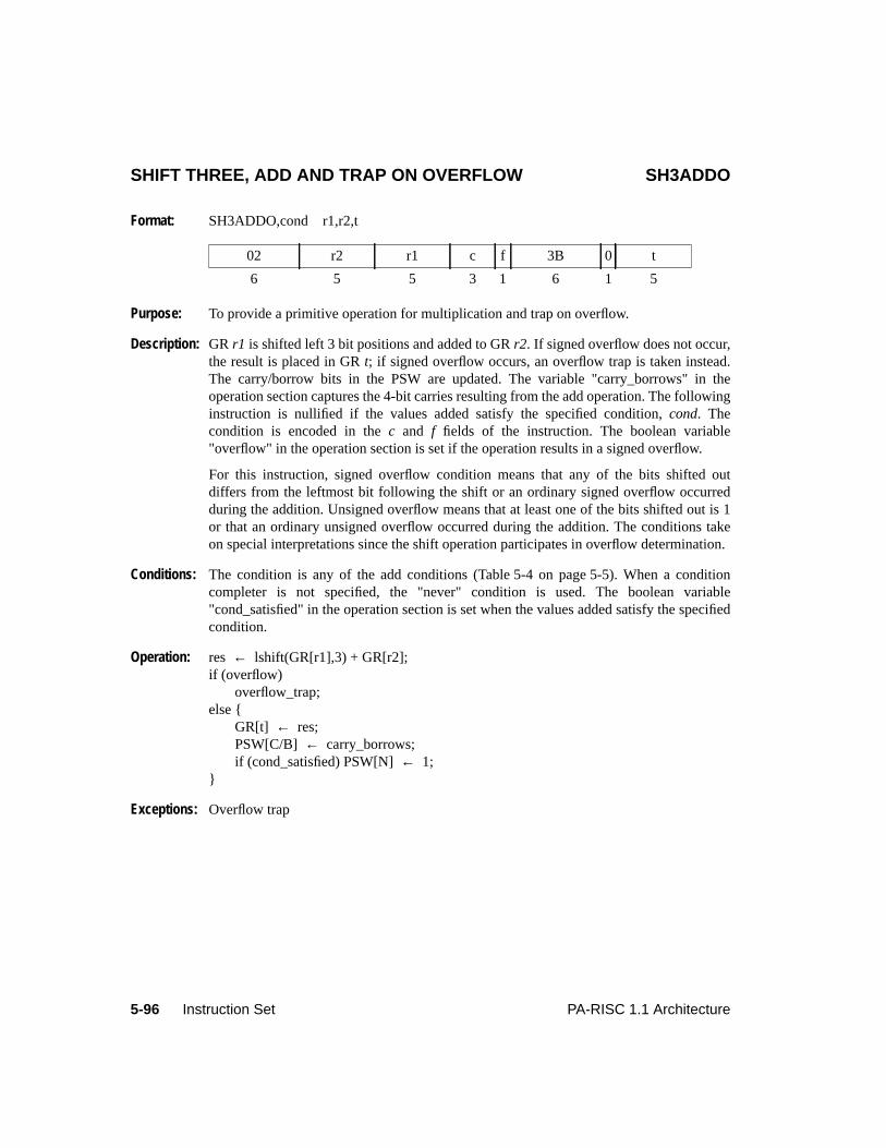
5-96 Instruction Set PA-RISC 1.1 Architecture
SHIFT THREE, ADD AND TRAP ON OVERFLOW SH3ADDO
Format: SH3ADDO,cond r1,r2,t
Purpose: To provide a primitive operation for multiplication and trap on overflow.
Description: GR r1 is shifted left 3 bit positions and added to GRr2. If signed overflow does not occur,the result is placed in GRt; if signed overflow occurs, an overflow trap is taken instead.The carry/borrow bits in the PSW are updated. The variable "carry_borrows" in theoperation section captures the 4-bit carries resulting from the add operation. The followinginstruction is nullified if the values added satisfy the specified condition,cond. Thecondition is encoded in thec and f fields of the instruction. The boolean variable"overflow" in the operation section is set if the operation results in a signed overflow.
For this instruction, signed overflow condition means that any of the bits shifted outdiffers from the leftmost bit following the shift or an ordinary signed overflow occurredduring the addition. Unsigned overflow means that at least one of the bits shifted out is 1or that an ordinary unsigned overflow occurred during the addition. The conditions takeon special interpretations since the shift operation participates in overflow determination.
Conditions: The condition is any of the add conditions (Table 5-4 on page 5-5). When a conditioncompleter is not specified, the "never" condition is used. The boolean variable"cond_satisfied" in the operation section is set when the values added satisfy the specifiedcondition.
Operation: res ← lshift(GR[r1],3) + GR[r2];if (overflow)
overflow_trap;else {
GR[t] ← res;PSW[C/B] ← carry_borrows;if (cond_satisfied) PSW[N]← 1;
}
Exceptions: Overflow trap
02 r2 r1 c f 3B 0 t
6 5 5 3 1 6 1 5
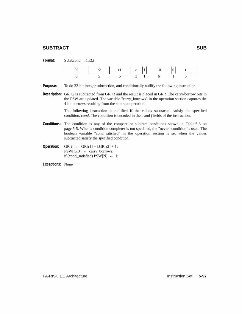
5-97PA-RISC 1.1 Architecture Instruction Set
SUBTRACT SUB
Format: SUB,cond r1,r2,t
Purpose: To do 32-bit integer subtraction, and conditionally nullify the following instruction.
Description: GR r2 is subtracted from GRr1 and the result is placed in GRt. The carry/borrow bits inthe PSW are updated. The variable "carry_borrows" in the operation section captures the4-bit borrows resulting from the subtract operation.
The following instruction is nullified if the values subtracted satisfy the specifiedcondition,cond. The condition is encoded in thec andf fields of the instruction.
Conditions: The condition is any of the compare or subtract conditions shown in Table 5-3 onpage 5-5. When a condition completer is not specified, the "never" condition is used. Theboolean variable "cond_satisfied" in the operation section is set when the valuessubtracted satisfy the specified condition.
Operation: GR[t] ← GR[r1] +∼GR[r2] + 1;PSW[C/B] ← carry_borrows;if (cond_satisfied) PSW[N]← 1;
Exceptions: None
02 r2 r1 c f 10 0 t
6 5 5 3 1 6 1 5
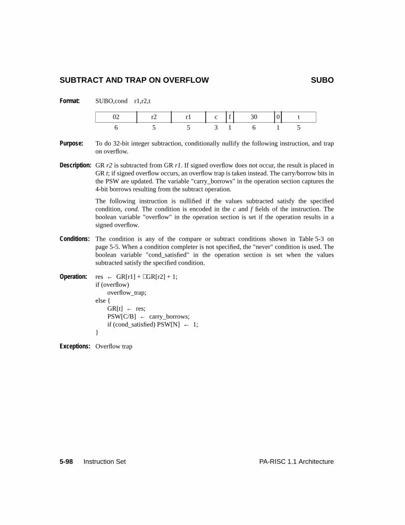
5-98 Instruction Set PA-RISC 1.1 Architecture
SUBTRACT AND TRAP ON OVERFLOW SUBO
Format: SUBO,cond r1,r2,t
Purpose: To do 32-bit integer subtraction, conditionally nullify the following instruction, and trapon overflow.
Description: GR r2 is subtracted from GRr1. If signed overflow does not occur, the result is placed inGR t; if signed overflow occurs, an overflow trap is taken instead. The carry/borrow bits inthe PSW are updated. The variable "carry_borrows" in the operation section captures the4-bit borrows resulting from the subtract operation.
The following instruction is nullified if the values subtracted satisfy the specifiedcondition, cond. The condition is encoded in thec and f fields of the instruction. Theboolean variable "overflow" in the operation section is set if the operation results in asigned overflow.
Conditions: The condition is any of the compare or subtract conditions shown in Table 5-3 onpage 5-5. When a condition completer is not specified, the "never" condition is used. Theboolean variable "cond_satisfied" in the operation section is set when the valuessubtracted satisfy the specified condition.
Operation: res ← GR[r1] +∼GR[r2] + 1;if (overflow)
overflow_trap;else {
GR[t] ← res;PSW[C/B] ← carry_borrows;if (cond_satisfied) PSW[N]← 1;
}
Exceptions: Overflow trap
02 r2 r1 c f 30 0 t
6 5 5 3 1 6 1 5
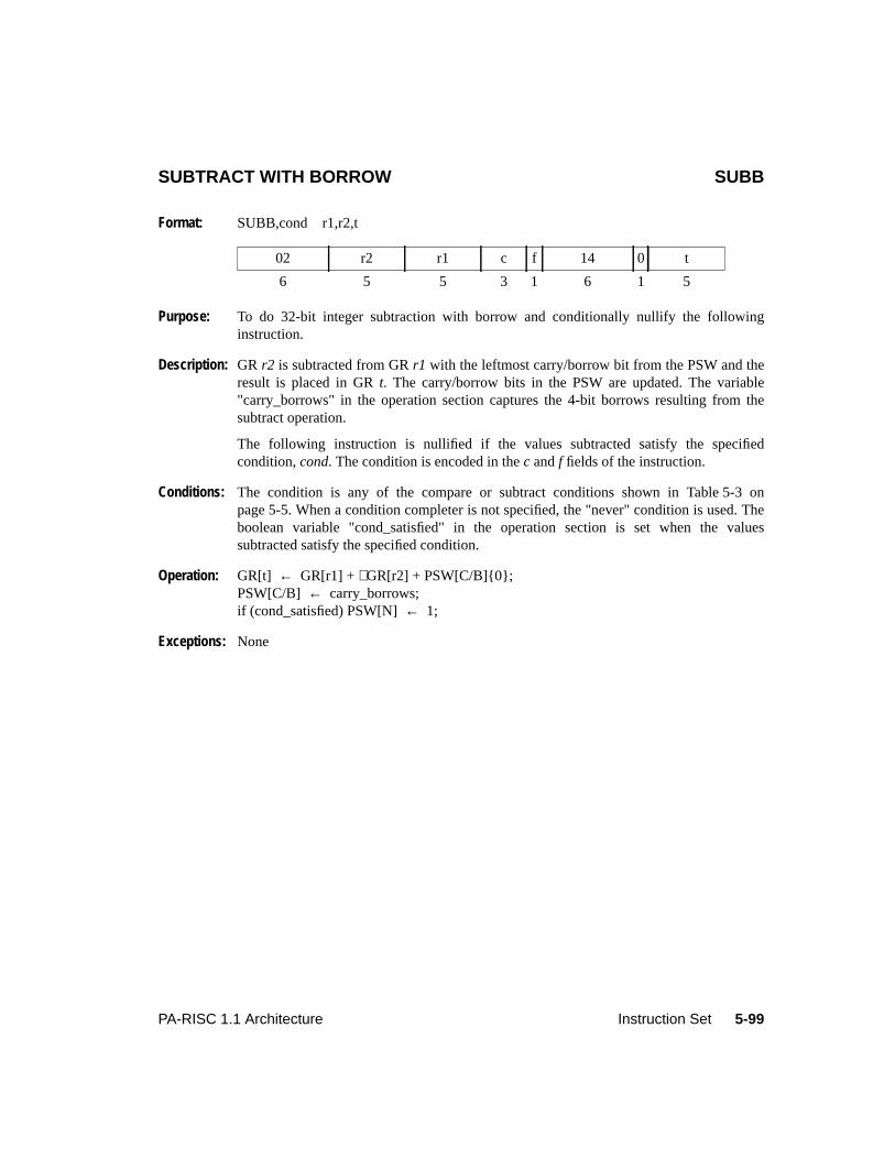
5-99PA-RISC 1.1 Architecture Instruction Set
SUBTRACT WITH BORROW SUBB
Format: SUBB,cond r1,r2,t
Purpose: To do 32-bit integer subtraction with borrow and conditionally nullify the followinginstruction.
Description: GR r2 is subtracted from GRr1 with the leftmost carry/borrow bit from the PSW and theresult is placed in GRt. The carry/borrow bits in the PSW are updated. The variable"carry_borrows" in the operation section captures the 4-bit borrows resulting from thesubtract operation.
The following instruction is nullified if the values subtracted satisfy the specifiedcondition,cond. The condition is encoded in thec andf fields of the instruction.
Conditions: The condition is any of the compare or subtract conditions shown in Table 5-3 onpage 5-5. When a condition completer is not specified, the "never" condition is used. Theboolean variable "cond_satisfied" in the operation section is set when the valuessubtracted satisfy the specified condition.
Operation: GR[t] ← GR[r1] +∼GR[r2] + PSW[C/B]{0};PSW[C/B] ← carry_borrows;if (cond_satisfied) PSW[N]← 1;
Exceptions: None
02 r2 r1 c f 14 0 t
6 5 5 3 1 6 1 5
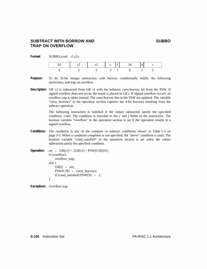
5-100 Instruction Set PA-RISC 1.1 Architecture
SUBTRACT WITH BORROW AND SUBBOTRAP ON OVERFLOW
Format: SUBBO,cond r1,r2,t
Purpose: To do 32-bit integer subtraction with borrow, conditionally nullify the followinginstruction, and trap on overflow.
Description: GR r2 is subtracted from GRr1 with the leftmost carry/borrow bit from the PSW. Ifsigned overflow does not occur, the result is placed in GRt. If signed overflow occurs, anoverflow trap is taken instead. The carry/borrow bits in the PSW are updated. The variable"carry_borrows" in the operation section captures the 4-bit borrows resulting from thesubtract operation.
The following instruction is nullified if the values subtracted satisfy the specifiedcondition, cond. The condition is encoded in thec and f fields of the instruction. Theboolean variable "overflow" in the operation section is set if the operation results in asigned overflow.
Conditions: The condition is any of the compare or subtract conditions shown in Table 5-3 onpage 5-5. When a condition completer is not specified, the "never" condition is used. Theboolean variable "cond_satisfied" in the operation section is set when the valuessubtracted satisfy the specified condition.
Operation: res ← GR[r1] +∼GR[r2] + PSW[C/B]{0};if (overflow)
overflow_trap;else {
GR[t] ← res;PSW[C/B] ← carry_borrows;if (cond_satisfied) PSW[N]← 1;
}
Exceptions: Overflow trap
02 r2 r1 c f 34 0 t
6 5 5 3 1 6 1 5
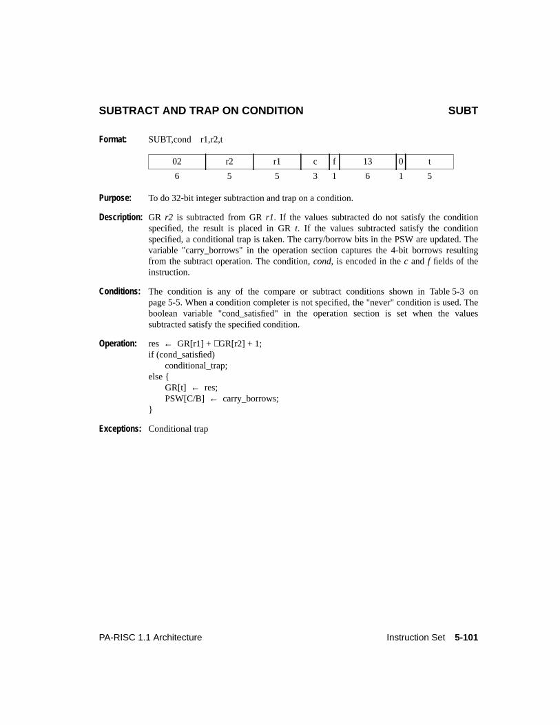
5-101PA-RISC 1.1 Architecture Instruction Set
SUBTRACT AND TRAP ON CONDITION SUBT
Format: SUBT,cond r1,r2,t
Purpose: To do 32-bit integer subtraction and trap on a condition.
Description: GR r2 is subtracted from GRr1. If the values subtracted do not satisfy the conditionspecified, the result is placed in GRt. If the values subtracted satisfy the conditionspecified, a conditional trap is taken. The carry/borrow bits in the PSW are updated. Thevariable "carry_borrows" in the operation section captures the 4-bit borrows resultingfrom the subtract operation. The condition,cond, is encoded in thec and f fields of theinstruction.
Conditions: The condition is any of the compare or subtract conditions shown in Table 5-3 onpage 5-5. When a condition completer is not specified, the "never" condition is used. Theboolean variable "cond_satisfied" in the operation section is set when the valuessubtracted satisfy the specified condition.
Operation: res ← GR[r1] +∼GR[r2] + 1;if (cond_satisfied)
conditional_trap;else {
GR[t] ← res;PSW[C/B] ← carry_borrows;
}
Exceptions: Conditional trap
02 r2 r1 c f 13 0 t
6 5 5 3 1 6 1 5
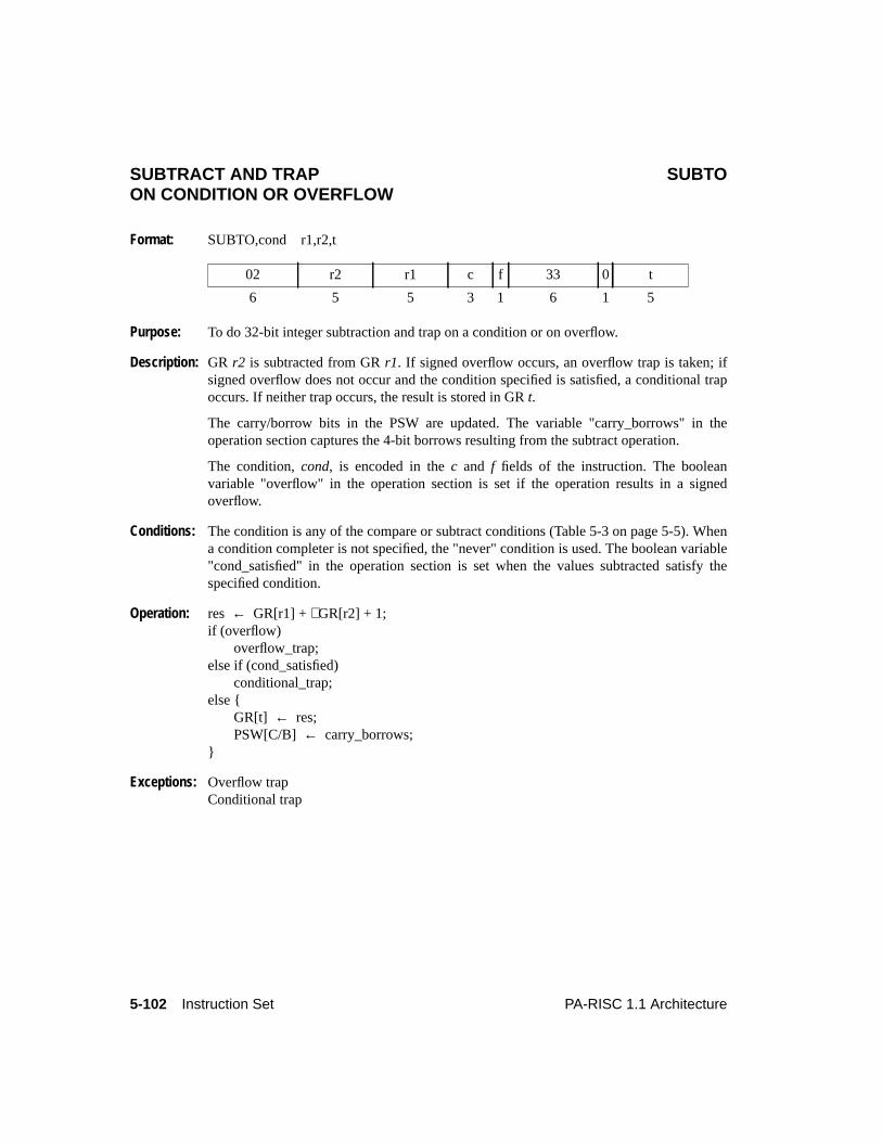
5-102 Instruction Set PA-RISC 1.1 Architecture
SUBTRACT AND TRAP SUBTOON CONDITION OR OVERFLOW
Format: SUBTO,cond r1,r2,t
Purpose: To do 32-bit integer subtraction and trap on a condition or on overflow.
Description: GR r2 is subtracted from GRr1. If signed overflow occurs, an overflow trap is taken; ifsigned overflow does not occur and the condition specified is satisfied, a conditional trapoccurs. If neither trap occurs, the result is stored in GRt.
The carry/borrow bits in the PSW are updated. The variable "carry_borrows" in theoperation section captures the 4-bit borrows resulting from the subtract operation.
The condition,cond, is encoded in thec and f fields of the instruction. The booleanvariable "overflow" in the operation section is set if the operation results in a signedoverflow.
Conditions: The condition is any of the compare or subtract conditions (Table 5-3 on page 5-5). Whena condition completer is not specified, the "never" condition is used. The boolean variable"cond_satisfied" in the operation section is set when the values subtracted satisfy thespecified condition.
Operation: res ← GR[r1] +∼GR[r2] + 1;if (overflow)
overflow_trap;else if (cond_satisfied)
conditional_trap;else {
GR[t] ← res;PSW[C/B] ← carry_borrows;
}
Exceptions: Overflow trapConditional trap
02 r2 r1 c f 33 0 t
6 5 5 3 1 6 1 5
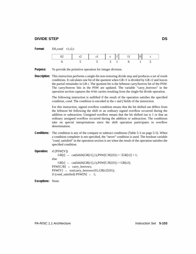
5-103PA-RISC 1.1 Architecture Instruction Set
DIVIDE STEP DS
Format: DS,cond r1,r2,t
Purpose: To provide the primitive operation for integer division.
Description: This instruction performs a single-bit non-restoring divide step and produces a set of resultconditions. It calculates one bit of the quotient when GRr1 is divided by GRr2 and leavesthe partial remainder in GRt. The quotient bit is the leftmost carry/borrow bit of the PSW.The carry/borrow bits in the PSW are updated. The variable "carry_borrows" in theoperation section captures the 4-bit carries resulting from the single-bit divide operation.
The following instruction is nullified if the result of the operation satisfies the specifiedcondition,cond. The condition is encoded in thec andf fields of the instruction.
For this instruction, signed overflow condition means that the bit shifted out differs fromthe leftmost bit following the shift or an ordinary signed overflow occurred during theaddition or subtraction. Unsigned overflow means that the bit shifted out is 1 or that anordinary unsigned overflow occurred during the addition or subtraction. The conditionstake on special interpretations since the shift operation participates in overflowdetermination.
Conditions: The condition is any of the compare or subtract conditions (Table 5-3 on page 5-5). Whena condition completer is not specified, the "never" condition is used. The boolean variable"cond_satisfied" in the operation section is set when the result of the operation satisfies thespecified condition.
Operation: if (PSW[V])GR[t] ← cat(lshift(GR[r1],1),PSW[C/B]{0}) +∼GR[r2] + 1;
elseGR[t] ← cat(lshift(GR[r1],1),PSW[C/B]{0}) + GR[r2];
PSW[C/B] ← carry_borrows;PSW[V] ← xor(carry_borrows{0},GR[r2]{0});if (cond_satisfied) PSW[N]← 1;
Exceptions: None
02 r2 r1 c f 11 0 t
6 5 5 3 1 6 1 5
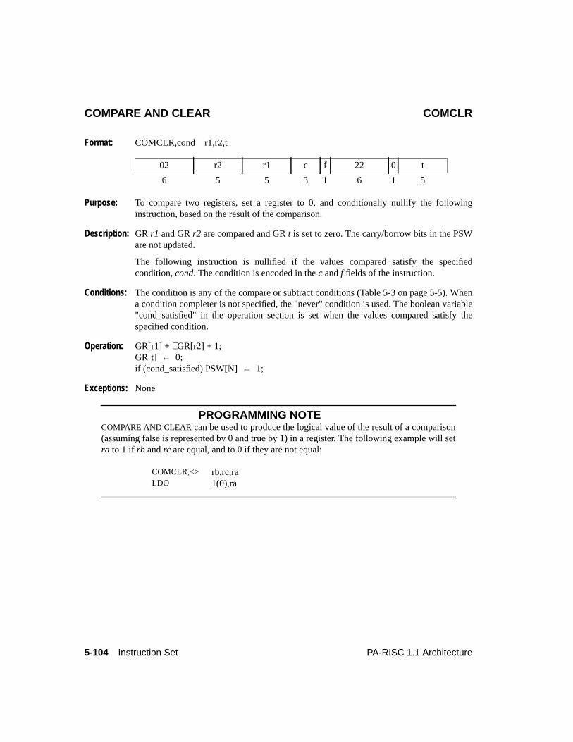
5-104 Instruction Set PA-RISC 1.1 Architecture
COMPARE AND CLEAR COMCLR
Format: COMCLR,cond r1,r2,t
Purpose: To compare two registers, set a register to 0, and conditionally nullify the followinginstruction, based on the result of the comparison.
Description: GR r1 and GRr2 are compared and GRt is set to zero. The carry/borrow bits in the PSWare not updated.
The following instruction is nullified if the values compared satisfy the specifiedcondition,cond. The condition is encoded in thec andf fields of the instruction.
Conditions: The condition is any of the compare or subtract conditions (Table 5-3 on page 5-5). Whena condition completer is not specified, the "never" condition is used. The boolean variable"cond_satisfied" in the operation section is set when the values compared satisfy thespecified condition.
Operation: GR[r1] + ∼GR[r2] + 1;GR[t] ← 0;if (cond_satisfied) PSW[N]← 1;
Exceptions: None
PROGRAMMING NOTECOMPARE AND CLEAR can be used to produce the logical value of the result of a comparison(assuming false is represented by 0 and true by 1) in a register. The following example will setra to 1 if rb andrc are equal, and to 0 if they are not equal:
02 r2 r1 c f 22 0 t
6 5 5 3 1 6 1 5
COMCLR,<> rb,rc,raLDO 1(0),ra
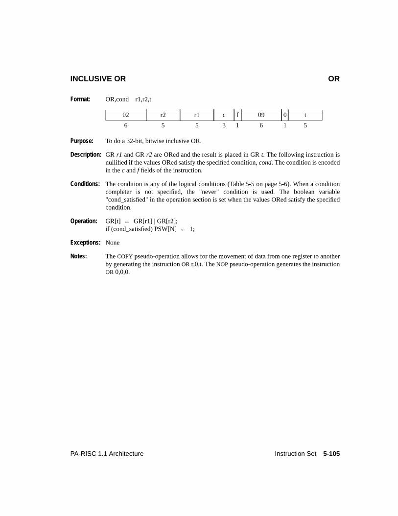
5-105PA-RISC 1.1 Architecture Instruction Set
INCLUSIVE OR OR
Format: OR,cond r1,r2,t
Purpose: To do a 32-bit, bitwise inclusive OR.
Description: GR r1 and GRr2 are ORed and the result is placed in GRt. The following instruction isnullified if the values ORed satisfy the specified condition,cond. The condition is encodedin thec andf fields of the instruction.
Conditions: The condition is any of the logical conditions (Table 5-5 on page 5-6). When a conditioncompleter is not specified, the "never" condition is used. The boolean variable"cond_satisfied" in the operation section is set when the values ORed satisfy the specifiedcondition.
Operation: GR[t] ← GR[r1] | GR[r2];if (cond_satisfied) PSW[N]← 1;
Exceptions: None
Notes: TheCOPY pseudo-operation allows for the movement of data from one register to anotherby generating the instructionOR r,0,t. TheNOP pseudo-operation generates the instructionOR 0,0,0.
02 r2 r1 c f 09 0 t
6 5 5 3 1 6 1 5
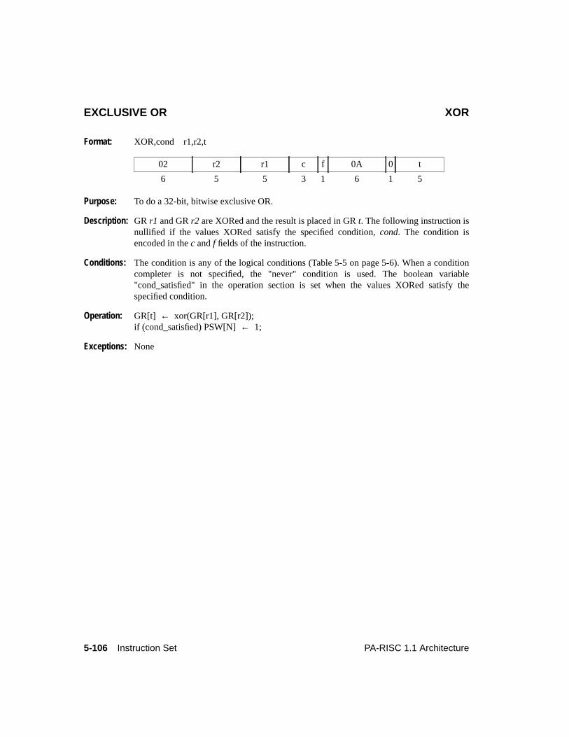
5-106 Instruction Set PA-RISC 1.1 Architecture
EXCLUSIVE OR XOR
Format: XOR,cond r1,r2,t
Purpose: To do a 32-bit, bitwise exclusive OR.
Description: GR r1 and GRr2 are XORed and the result is placed in GRt. The following instruction isnullified if the values XORed satisfy the specified condition,cond. The condition isencoded in thec andf fields of the instruction.
Conditions: The condition is any of the logical conditions (Table 5-5 on page 5-6). When a conditioncompleter is not specified, the "never" condition is used. The boolean variable"cond_satisfied" in the operation section is set when the values XORed satisfy thespecified condition.
Operation: GR[t] ← xor(GR[r1], GR[r2]);if (cond_satisfied) PSW[N]← 1;
Exceptions: None
02 r2 r1 c f 0A 0 t
6 5 5 3 1 6 1 5
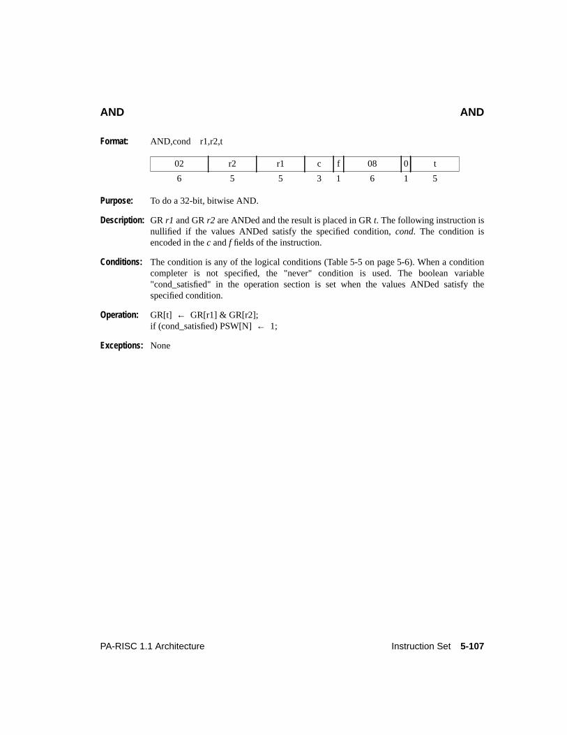
5-107PA-RISC 1.1 Architecture Instruction Set
AND AND
Format: AND,cond r1,r2,t
Purpose: To do a 32-bit, bitwise AND.
Description: GR r1 and GRr2 are ANDed and the result is placed in GRt. The following instruction isnullified if the values ANDed satisfy the specified condition,cond. The condition isencoded in thec andf fields of the instruction.
Conditions: The condition is any of the logical conditions (Table 5-5 on page 5-6). When a conditioncompleter is not specified, the "never" condition is used. The boolean variable"cond_satisfied" in the operation section is set when the values ANDed satisfy thespecified condition.
Operation: GR[t] ← GR[r1] & GR[r2];if (cond_satisfied) PSW[N]← 1;
Exceptions: None
02 r2 r1 c f 08 0 t
6 5 5 3 1 6 1 5
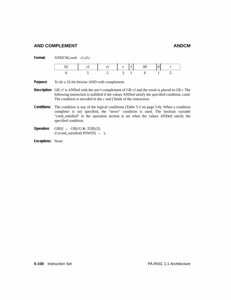
5-108 Instruction Set PA-RISC 1.1 Architecture
AND COMPLEMENT ANDCM
Format: ANDCM,cond r1,r2,t
Purpose: To do a 32-bit bitwise AND with complement.
Description: GR r1 is ANDed with the one’s complement of GRr2 and the result is placed in GRt. Thefollowing instruction is nullified if the values ANDed satisfy the specified condition,cond.The condition is encoded in thec andf fields of the instruction.
Conditions: The condition is any of the logical conditions (Table 5-5 on page 5-6). When a conditioncompleter is not specified, the "never" condition is used. The boolean variable"cond_satisfied" in the operation section is set when the values ANDed satisfy thespecified condition.
Operation: GR[t] ← GR[r1] & ∼GR[r2];if (cond_satisfied) PSW[N]← 1;
Exceptions: None
02 r2 r1 c f 00 0 t
6 5 5 3 1 6 1 5
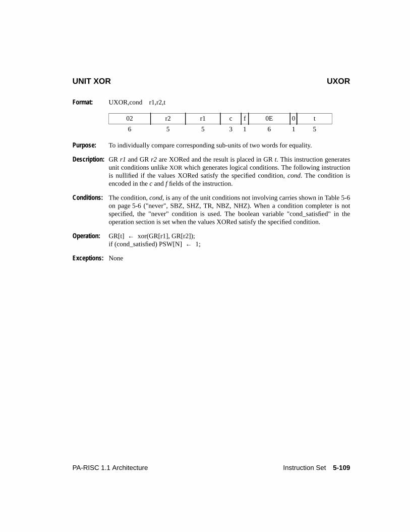
5-109PA-RISC 1.1 Architecture Instruction Set
UNIT XOR UXOR
Format: UXOR,cond r1,r2,t
Purpose: To individually compare corresponding sub-units of two words for equality.
Description: GR r1 and GRr2 are XORed and the result is placed in GRt. This instruction generatesunit conditions unlikeXOR which generates logical conditions. The following instructionis nullified if the values XORed satisfy the specified condition,cond. The condition isencoded in thec andf fields of the instruction.
Conditions: The condition,cond, is any of the unit conditions not involving carries shown in Table 5-6on page 5-6 ("never", SBZ, SHZ, TR, NBZ, NHZ). When a condition completer is notspecified, the "never" condition is used. The boolean variable "cond_satisfied" in theoperation section is set when the values XORed satisfy the specified condition.
Operation: GR[t] ← xor(GR[r1], GR[r2]);if (cond_satisfied) PSW[N]← 1;
Exceptions: None
02 r2 r1 c f 0E 0 t
6 5 5 3 1 6 1 5
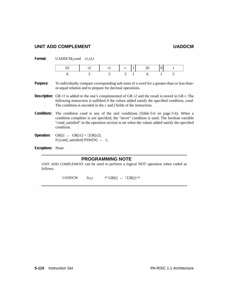
5-110 Instruction Set PA-RISC 1.1 Architecture
UNIT ADD COMPLEMENT UADDCM
Format: UADDCM,cond r1,r2,t
Purpose: To individually compare corresponding sub-units of a word for a greater-than or less-than-or-equal relation and to prepare for decimal operations.
Description: GR r1 is added to the one’s complemented of GRr2 and the result is stored in GRt. Thefollowing instruction is nullified if the values added satisfy the specified condition,cond.The condition is encoded in thec andf fields of the instruction.
Conditions: The conditioncond is any of the unit conditions (Table 5-6 on page 5-6). When acondition completer is not specified, the "never" condition is used. The boolean variable"cond_satisfied" in the operation section is set when the values added satisfy the specifiedcondition.
Operation: GR[t] ← GR[r1] +∼GR[r2];if (cond_satisfied) PSW[N]← 1;
Exceptions: None
PROGRAMMING NOTEUNIT ADD COMPLEMENT can be used to perform a logical NOT operation when coded asfollows:
02 r2 r1 c f 26 0 t
6 5 5 3 1 6 1 5
UADDCM 0,r,t /* GR[t] ← ∼GR[r] */
5-111PA-RISC 1.1 Architecture Instruction Set
UNIT ADD COMPLEMENT AND UADDCMTTRAP ON CONDITION
Format: UADDCMT,cond r1,r2,t
Purpose: To individually compare corresponding sub-units of a word for a greater-than or less-than-or-equal a relation and trap if the specified condition is satisfied by any sub-unit.
Description: GR r1 is added to the one’s complement of GRr2. If the condition,cond, is satisfied bythe values added a conditional trap is taken; otherwise the result is stored in GRt. Thecondition is encoded in thec andf fields of the instruction.
Conditions: The conditioncond is any of the unit conditions (Table 5-6 on page 5-6). When acondition completer is not specified, the "never" condition is used. The boolean variable"cond_satisfied" in the operation section is set when the values added satisfy the specifiedcondition.
Operation: res ← GR[r1] +∼GR[r2];if (cond_satisfied)
conditional_trap;else
GR[t] ← res;
Exceptions: Conditional trap
PROGRAMMING NOTEUNIT ADD COMPLEMENT AND TRAP ON CONDITION can be used to check decimal validityand to pre-bias decimal numbers.ra contains the number to be checked andrt will contain thenumber plus the bias as result of theUADDCMT operation.
02 r2 r1 c f 27 0 t
6 5 5 3 1 6 1 5
NINES .equ X’99999999LDIL l%NINES,ninesLDO r%NINES(nines),ninesUADDCMT,SDC ra,nines,rt
5-112 Instruction Set PA-RISC 1.1 Architecture
DECIMAL CORRECT DCOR
Format: DCOR,cond r,t
Purpose: To separately correct the eight BCD digits of the result of an addition or subtraction.
Description: Every digit of GRr corresponding to a bit which is 0 in PSW C/B-bits has 6 subtractedfrom it. The result is stored in GRt. The following instruction is nullified if the result ofthe operation satisfies the specified conditioncond. The condition is encoded in thec andffields of the instruction.
Conditions: The conditioncond is any of the unit conditions (Table 5-6 on page 5-6). When acondition completer is not specified, the "never" condition is used. The boolean variable"cond_satisfied" in the operation section is set when the result of the operation satisfies thespecified condition.
Operation: GR[t] ← GR[r] - cat(0x6*(1 - PSW[C/B]{0}), 0x6*(1 - PSW[C/B]{1}),0x6*(1 - PSW[C/B]{2}), 0x6*(1 - PSW[C/B]{3}),0x6*(1 - PSW[C/B]{4}), 0x6*(1 - PSW[C/B]{5}),0x6*(1 - PSW[C/B]{6}), 0x6*(1 - PSW[C/B]{7}));
if (cond_satisfied) PSW[N]← 1;
Exceptions: None
02 r 0 c f 2E 0 t
6 5 5 3 1 6 1 5
5-113PA-RISC 1.1 Architecture Instruction Set
PROGRAMMING NOTEDECIMAL CORRECT can be used to take the sum of 32-bit BCD values.ra, rb, rc, andrd eachcontain a 32-bit BCD value andrt will hold the result at the end of the sequence. TheUADDCM operation is used to pre-bias the value inra in order to perform BCD arithmetic. TheIDCOR operations between theADD operations are used to re-adjust the BCD bias of the result.The finalDCOR operation is used to remove the bias and leave the value inrt in BCD format.
NINES .equ 0x99999999LDIL l%NINES,ninesLDO r%NINES(nines),ninesUADDCM ra,nines,rt ; pre-bias first operandADD rt,rb,rt ; add in the next valueIDCOR rt,rt ; correct result, retaining biasADD rt,rc,rt ; add in the next valueIDCOR rt,rt ; correct result, retaining biasADD rt,rd,rt ; add in the next valueDCOR rt,rt ; final correction
5-114 Instruction Set PA-RISC 1.1 Architecture
INTERMEDIATE DECIMAL CORRECT IDCOR
Format: IDCOR,cond r,t
Purpose: To separately correct the eight BCD digits of the result of an addition or subtraction.
Description: Every digit of GRr corresponding to a bit which is on in PSW C/B-bits has 6 added to it.The result is stored in GRt. The following instruction is nullified if the result of theoperation satisfies the specified conditioncond. The condition is encoded in thec and ffields of the instruction.
Conditions: The conditioncond is any of the unit conditions (Table 5-6 on page 5-6). When acondition completer is not specified, the "never" condition is used. The boolean variable"cond_satisfied" in the operation section is set when the result of the operation satisfies thespecified condition.
Operation: GR[t] ← GR[r] + cat(0x6*PSW[C/B]{0}, 0x6*PSW[C/B]{1},0x6*PSW[C/B]{2}, 0x6*PSW[C/B]{3},0x6*PSW[C/B]{4}, 0x6*PSW[C/B]{5},0x6*PSW[C/B]{6}, 0x6*PSW[C/B]{7});
if (cond_satisfied) PSW[N]← 1;
Exceptions: None
02 r 0 c f 2F 0 t
6 5 5 3 1 6 1 5
5-115PA-RISC 1.1 Architecture Instruction Set
ADD TO IMMEDIATE ADDI
Format: ADDI,cond i,r,t
Purpose: To add an immediate value to a register and conditionally nullify the following instruction.
Description: The sign-extended immediate valuei is added to GRr and the result is stored in GRt. Theimmediate value is encoded into theim11 field. The carry/borrow bits in the PSW areupdated. The variable "carry_borrows" in the operation section captures the 4-bit carriesresulting from the add operation.
The following instruction is nullified if the values added satisfy the specified condition,cond. The condition is encoded in thec andf fields of the instruction.
Conditions: The condition is any of the add conditions (Table 5-4 on page 5-5). When a conditioncompleter is not specified, the "never" condition is used. The boolean variable"cond_satisfied" in the operation section is set when the values added satisfy the specifiedcondition.
Operation: GR[t] ← low_sign_ext(im11,11) + GR[r];PSW[C/B] ← carry_borrows;if (cond_satisfied) PSW[N]← 1;
Exceptions: None
2D r t c f 0 im11
6 5 5 3 1 1 11
5-116 Instruction Set PA-RISC 1.1 Architecture
ADD TO IMMEDIATE AND TRAP ON OVERFLOW ADDIO
Format: ADDIO,cond i,r,t
Purpose: To add an immediate value to a register, conditionally nullify the following instruction,and trap on overflow.
Description: The sign-extended immediate valuei and GR r are added. The immediate value isencoded into theim11 field. If signed overflow does not occur, the result is stored in GRt,and the carry/borrow bits in the PSW are updated. If signed overflow occurs, an overflowtrap is taken instead. The variable "carry_borrows" in the operation section captures the 4-bit carries resulting from the add operation.
The following instruction is nullified if the values added satisfy the specified condition,cond. The condition is encoded in thec andf fields of the instruction. The boolean variable"overflow" in the operation section is set if the operation results in a signed overflow.
Conditions: The condition is any of the add conditions (Table 5-4 on page 5-5). When a conditioncompleter is not specified, the "never" condition is used. The boolean variable"cond_satisfied" in the operation section is set when the values added satisfy the specifiedcondition.
Operation: res ← low_sign_ext(im11,11) + GR[r];if (overflow)
overflow_trap;else {
GR[t] ← res;PSW[C/B] ← carry_borrows;if (cond_satisfied) PSW[N]← 1;
}
Exceptions: Overflow trap
2D r t c f 1 im11
6 5 5 3 1 1 11
5-117PA-RISC 1.1 Architecture Instruction Set
ADD TO IMMEDIATE AND TRAP ON CONDITION ADDIT
Format: ADDIT,cond i,r,t
Purpose: To add an immediate value to a register and trap on a condition.
Description: The sign-extended immediate valuei and GR r are added. The immediate value isencoded into theim11 field. If the specified condition,cond, is satisfied by the valuesadded, a conditional trap occurs; otherwise, the result is stored in GRt and the carry/borrow bits in the PSW are updated. The variable "carry_borrows" in the operation sectioncaptures the 4-bit carries resulting from the add operation. The condition is encoded in thec andf fields of the instruction.
Conditions: The condition is any of the add conditions (Table 5-4 on page 5-5). When a conditioncompleter is not specified, the "never" condition is used. The boolean variable"cond_satisfied" in the operation section is set when the values added satisfy the specifiedcondition.
Operation: res ← low_sign_ext(im11,11) + GR[r];if (cond_satisfied)
conditional_trap;else {
GR[t] ← res;PSW[C/B] ← carry_borrows;
}
Exceptions: Conditional trap
2C r t c f 0 im11
6 5 5 3 1 1 11
5-118 Instruction Set PA-RISC 1.1 Architecture
ADD TO IMMEDIATE AND ADDITOTRAP ON CONDITION OR OVERFLOW
Format: ADDITO,cond i,r,t
Purpose: To add an immediate value to a register and trap on a condition or on overflow.
Description: The sign-extended immediate valuei and GR r are added. The immediate value isencoded into theim11 field. If signed overflow occurs, an overflow trap is taken. If signedoverflow does not occur and the specified condition,cond, is satisfied, a conditional trapoccurs. If overflow does not occur and the specified condition is not satisfied, the result isstored in GRt, and the carry/borrow bits in the PSW are updated.
The variable "carry_borrows" in the operation section captures the 4-bit carries resultingfrom the add operation. The boolean variable "overflow" in the operation section is set ifthe operation results in a signed overflow.
Conditions: The condition is any of the add conditions (Table 5-4 on page 5-5). When a conditioncompleter is not specified, the "never" condition is used. The boolean variable"cond_satisfied" in the operation section is set when the values added satisfy the specifiedcondition.
Operation: res ← low_sign_ext(im11,11) + GR[r];if (overflow)
overflow_trap;else if (cond_satisfied)
conditional_trap;else {
GR[t] ← res;PSW[C/B] ← carry_borrows;
}
Exceptions: Overflow trapConditional trap
2C r t c f 1 im11
6 5 5 3 1 1 11
5-119PA-RISC 1.1 Architecture Instruction Set
SUBTRACT FROM IMMEDIATE SUBI
Format: SUBI,cond i,r,t
Purpose: To subtract a register from an immediate value and conditionally nullify the followinginstruction.
Description: GR r is subtracted from the sign-extended immediate valuei and the result is stored in GRt. The immediate value is encoded into theim11 field. The carry/borrow bits in the PSWare updated. The variable "carry_borrows" in the operation section captures the 4-bitcarries resulting from the subtract operation. The following instruction is nullified if thevalues subtracted satisfy the specified condition,cond. The condition is encoded in thecandf fields of the instruction.
Conditions: The condition is any of the compare or subtract conditions (Table 5-3 on page 5-5). Whena condition completer is not specified, the "never" condition is used. The boolean variable"cond_satisfied" in the operation section is set when the values subtracted satisfy thespecified condition.
Operation: GR[t] ← low_sign_ext(im11,11) +∼GR[r] + 1;PSW[C/B] ← carry_borrows;if (cond_satisfied) PSW[N]← 1;
Exceptions: None
PROGRAMMING NOTESUBTRACT FROM IMMEDIATE can be used to perform a logical NOT operation when codedas follows:
25 r t c f 0 im11
6 5 5 3 1 1 11
SUBI -1,r,t /* GR[t] ← ∼GR[r] all PSW[C/B] are set to ones */
5-120 Instruction Set PA-RISC 1.1 Architecture
SUBTRACT FROM IMMEDIATE AND SUBIOTRAP ON OVERFLOW
Format: SUBIO,cond i,r,t
Purpose: To subtract a register from an immediate value, conditionally nullify the followinginstruction, and trap on overflow.
Description: GR r is subtracted from the sign-extended immediate valuei. The immediate value isencoded into theim11 field. If signed overflow does not occur, the result is stored in GRt,and the carry/borrow bits in the PSW are updated. If signed overflow occurs, an overflowtrap is taken instead. The variable "carry_borrows" in the operation section captures the 4-bit carries resulting from the subtract operation. The following instruction is nullified ifthe values subtracted satisfy the specified condition,cond. The condition is encoded in thec andf fields of the instruction.
Conditions: The condition is any of the compare or subtract conditions (Table 5-3 on page 5-5). Whena condition completer is not specified, the "never" condition is used. The boolean variable"cond_satisfied" in the operation section is set when the values subtracted satisfy thespecified condition.
Operation: res ← low_sign_ext(im11,11) +∼GR[r] + 1;if (overflow)
overflow_trap;else {
GR[t] ← res;PSW[C/B] ← carry_borrows;if (cond_satisfied) PSW[N]← 1;
}
Exceptions: Overflow trap
25 r t c f 1 im11
6 5 5 3 1 1 11
5-121PA-RISC 1.1 Architecture Instruction Set
COMPARE IMMEDIATE AND CLEAR COMICLR
Format: COMICLR,cond i,r,t
Purpose: To compare an immediate value with the contents of a register, set a register to 0, andconditionally nullify the following instruction.
Description: The sign-extended immediate and GRr are compared and GRt is set to zero. Theimmediate value is encoded into theim11 field. The following instruction is nullified if thevalues compared satisfy the specified condition,cond. The condition is encoded in thecandf fields of the instruction.
Conditions: The condition is any of the compare or subtract conditions (Table 5-3 on page 5-5). Whena condition completer is not specified, the "never" condition is used. The boolean variable"cond_satisfied" in the operation section is set when the values compared satisfy thespecified condition.
Operation: low_sign_ext(im11,11) +∼GR[r] + 1;GR[t] ← 0;if (cond_satisfied) PSW[N]← 1;
Exceptions: None
24 r t c f 0 im11
6 5 5 3 1 1 11
5-122 Instruction Set PA-RISC 1.1 Architecture
VARIABLE SHIFT DOUBLE VSHD
Format: VSHD,cond r1,r2,t
Purpose: To shift a pair of registers by a variable amount and conditionally nullify the followinginstructions.
Description: The rightmost 31 bits of GRr1 are concatenated with the 32 bits of GRr2 and shiftedright the number of bits given by the Shift Amount Register (CR 11). The rightmost 32bits of the result are stored in GRt. The following instruction is nullified if the result of theoperation satisfies the specified condition,cond. The condition is encoded in thec field ofthe instruction.
Conditions: The condition is any of the extract/deposit conditions (Table 5-7 on page 5-7). When acondition completer is not specified, the "never" condition is used. The boolean variable"cond_satisfied" in the operation section is set when the result of the operation satisfies thespecified condition.
Operation: GR[t] ← rshift(cat(GR[r1]{1..31},GR[r2]),CR[11]){32..63};if (cond_satisfied) PSW[N]← 1;
Exceptions: None
PROGRAMMING NOTEA logical right shift of GRr by a variable amount contained in GRp leaving the result in GRtmay be done by the following sequence:
An arithmetic right shift can be done with an extract instruction. SeeVARIABLE EXTRACTSIGNED on page 5-125 for an example.
If r1 andr2 name the same register, its contents are rotated and placed in GRt. SeeSHIFTDOUBLE on page 5-123 for an example.
34 r2 r1 c 0 0 t
6 5 5 3 3 5 5
MTSAR pVSHD 0,r,t
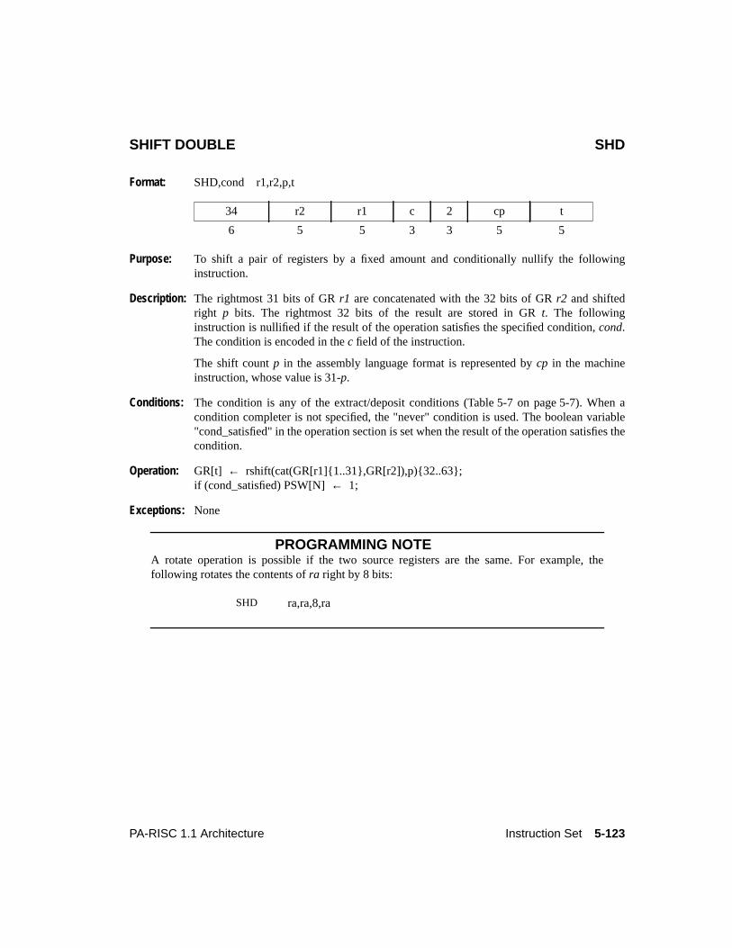
5-123PA-RISC 1.1 Architecture Instruction Set
SHIFT DOUBLE SHD
Format: SHD,cond r1,r2,p,t
Purpose: To shift a pair of registers by a fixed amount and conditionally nullify the followinginstruction.
Description: The rightmost 31 bits of GRr1 are concatenated with the 32 bits of GRr2 and shiftedright p bits. The rightmost 32 bits of the result are stored in GRt. The followinginstruction is nullified if the result of the operation satisfies the specified condition,cond.The condition is encoded in thec field of the instruction.
The shift countp in the assembly language format is represented bycp in the machineinstruction, whose value is 31-p.
Conditions: The condition is any of the extract/deposit conditions (Table 5-7 on page 5-7). When acondition completer is not specified, the "never" condition is used. The boolean variable"cond_satisfied" in the operation section is set when the result of the operation satisfies thecondition.
Operation: GR[t] ← rshift(cat(GR[r1]{1..31},GR[r2]),p){32..63};if (cond_satisfied) PSW[N]← 1;
Exceptions: None
PROGRAMMING NOTEA rotate operation is possible if the two source registers are the same. For example, thefollowing rotates the contents ofra right by 8 bits:
34 r2 r1 c 2 cp t
6 5 5 3 3 5 5
SHD ra,ra,8,ra
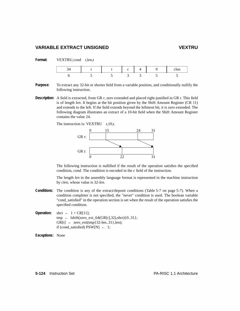
5-124 Instruction Set PA-RISC 1.1 Architecture
VARIABLE EXTRACT UNSIGNED VEXTRU
Format: VEXTRU,cond r,len,t
Purpose: To extract any 32-bit or shorter field from a variable position, and conditionally nullify thefollowing instruction.
Description: A field is extracted, from GRr, zero extended and placed right-justified in GRt. This fieldis of lengthlen. It begins at the bit position given by the Shift Amount Register (CR 11)and extends to the left. If the field extends beyond the leftmost bit, it is zero extended. Thefollowing diagram illustrates an extract of a 10-bit field when the Shift Amount Registercontains the value 24.
The instruction is: VEXTRU r,10,t.
The following instruction is nullified if the result of the operation satisfies the specifiedcondition,cond. The condition is encoded in thec field of the instruction.
The lengthlen in the assembly language format is represented in the machine instructionby clen, whose value is 32-len.
Conditions: The condition is any of the extract/deposit conditions (Table 5-7 on page 5-7). When acondition completer is not specified, the "never" condition is used. The boolean variable"cond_satisfied" in the operation section is set when the result of the operation satisfies thespecified condition.
Operation: shct ← 1 + CR[11];tmp ← lshift(zero_ext_64(GR[r],32),shct){0..31};GR[t] ← zero_ext(tmp{32-len..31},len);if (cond_satisfied) PSW[N]← 1;
Exceptions: None
34 r t c 4 0 clen
6 5 5 3 3 5 5
0 15 24 31
0 22 31
GR r:
GR t:
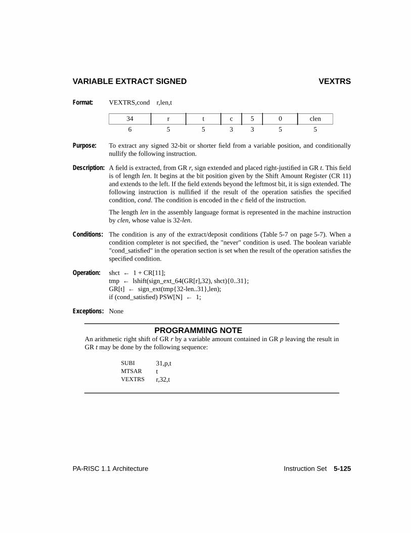
5-125PA-RISC 1.1 Architecture Instruction Set
VARIABLE EXTRACT SIGNED VEXTRS
Format: VEXTRS,cond r,len,t
Purpose: To extract any signed 32-bit or shorter field from a variable position, and conditionallynullify the following instruction.
Description: A field is extracted, from GRr, sign extended and placed right-justified in GRt. This fieldis of lengthlen. It begins at the bit position given by the Shift Amount Register (CR 11)and extends to the left. If the field extends beyond the leftmost bit, it is sign extended. Thefollowing instruction is nullified if the result of the operation satisfies the specifiedcondition,cond. The condition is encoded in thec field of the instruction.
The lengthlen in the assembly language format is represented in the machine instructionby clen, whose value is 32-len.
Conditions: The condition is any of the extract/deposit conditions (Table 5-7 on page 5-7). When acondition completer is not specified, the "never" condition is used. The boolean variable"cond_satisfied" in the operation section is set when the result of the operation satisfies thespecified condition.
Operation: shct ← 1 + CR[11];tmp ← lshift(sign_ext_64(GR[r],32), shct){0..31};GR[t] ← sign_ext(tmp{32-len..31},len);if (cond_satisfied) PSW[N]← 1;
Exceptions: None
PROGRAMMING NOTEAn arithmetic right shift of GRr by a variable amount contained in GRp leaving the result inGR t may be done by the following sequence:
34 r t c 5 0 clen
6 5 5 3 3 5 5
SUBI 31,p,tMTSAR tVEXTRS r,32,t
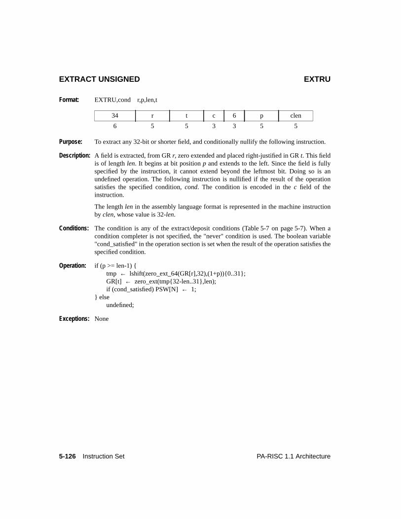
5-126 Instruction Set PA-RISC 1.1 Architecture
EXTRACT UNSIGNED EXTRU
Format: EXTRU,cond r,p,len,t
Purpose: To extract any 32-bit or shorter field, and conditionally nullify the following instruction.
Description: A field is extracted, from GRr, zero extended and placed right-justified in GRt. This fieldis of lengthlen. It begins at bit positionp and extends to the left. Since the field is fullyspecified by the instruction, it cannot extend beyond the leftmost bit. Doing so is anundefined operation. The following instruction is nullified if the result of the operationsatisfies the specified condition,cond. The condition is encoded in thec field of theinstruction.
The lengthlen in the assembly language format is represented in the machine instructionby clen, whose value is 32-len.
Conditions: The condition is any of the extract/deposit conditions (Table 5-7 on page 5-7). When acondition completer is not specified, the "never" condition is used. The boolean variable"cond_satisfied" in the operation section is set when the result of the operation satisfies thespecified condition.
Operation: if (p >= len-1) {tmp ← lshift(zero_ext_64(GR[r],32),(1+p)){0..31};GR[t] ← zero_ext(tmp{32-len..31},len);if (cond_satisfied) PSW[N]← 1;
} elseundefined;
Exceptions: None
34 r t c 6 p clen
6 5 5 3 3 5 5
5-127PA-RISC 1.1 Architecture Instruction Set
EXTRACT SIGNED EXTRS
Format: EXTRS,cond r,p,len,t
Purpose: To extract any signed 32-bit or shorter field, and conditionally nullify the followinginstruction.
Description: A field is extracted, from GRr, sign extended, and placed right-justified in GRt. This fieldis of lengthlen. It begins at bit positionp and extends to the left. Since the field is fullyspecified by the instruction, it cannot extend beyond the leftmost bit. Doing so is anundefined operation. The following instruction is nullified if the result of the operationsatisfies the specified condition,cond. The condition is encoded in thec field of theinstruction.
The lengthlen in the assembly language format is represented in the machine instructionby clen, whose value is 32-len.
Conditions: The condition is any of the extract/deposit conditions (Table 5-7 on page 5-7). When acondition completer is not specified, the "never" condition is used. The boolean variable"cond_satisfied" in the operation section is set when the result of the operation satisfies thespecified condition.
Operation: if (p >= len-1) {tmp ← lshift(sign_ext_64(GR[r],32),(1+p)){0..31};GR[t] ← sign_ext(tmp{32-len..31},len);if (cond_satisfied) PSW[N]← 1;
} elseundefined;
Exceptions: None
34 r t c 7 p clen
6 5 5 3 3 5 5
5-128 Instruction Set PA-RISC 1.1 Architecture
VARIABLE DEPOSIT VDEP
Format: VDEP,cond r,len,t
Purpose: To deposit a value into a register at a variable position, and conditionally nullify thefollowing instruction.
Description: A right-justified field from GRr is deposited (merged) in GRt. This field is of lengthlen.It begins at the bit position given by the Shift Amount Register (CR 11) and extends to theleft. If the field extends beyond the leftmost bit, the field is truncated and the higher bitsare ignored. The remainder of GRt is unchanged. The following diagram illustrates adeposit of a 10-bit field when the Shift Amount Register contains the value 24.
The instruction is: VDEP r,10,t.
The following instruction is nullified if the result of the operation satisfies the specifiedcondition,cond. The condition is encoded in thec field of the instruction. The lengthlenin the assembly language format is represented in the machine instruction byclen, whosevalue is 32-len.
Conditions: The condition is any of the extract/deposit conditions (Table 5-7 on page 5-7). When acondition completer is not specified, the "never" condition is used. The boolean variable"cond_satisfied" in the operation section is set when the result of the operation satisfies thespecified condition.
Operation: tpos ← CR[11];if (tpos < len-1)
GR[t]{0..tpos} ← GR[r]{31-tpos..31};else
GR[t]{tpos-len+1..tpos}← GR[r]{32-len..31};if (cond_satisfied) PSW[N]← 1;
Exceptions: None
35 t r c 1 0 clen
6 5 5 3 3 5 5
0
15 24
31
0
22
31
GR t:
GR r:
5-129PA-RISC 1.1 Architecture Instruction Set
DEPOSIT DEP
Format: DEP,cond r,p,len,t
Purpose: To deposit a value into a register at a constant position, and conditionally nullify thefollowing instruction.
Description: A right-justified field from GRr is deposited (merged) in GRt. This field is of lengthlen.It begins at the bit positionp and extends to the left. Since the field is fully specified by theinstruction, it cannot extend beyond the leftmost bit. Doing so is an undefined operation.The remainder of GRt is unchanged. The following diagram illustrates a deposit of a 10-bit field whenp specifies the value 24.
The instruction is: DEP r,24,10,t.
The following instruction is nullified if the result of the operation satisfies the specifiedcondition,cond. The condition is encoded in thec field of the instruction. The lengthlenin the assembly language format is represented in the machine instruction byclen, whosevalue is 32-len. The bit positionp in the assembly language format is represented bycp inthe machine instruction, whose value is 31-p.
Conditions: The condition is any of the extract/deposit conditions (Table 5-7 on page 5-7). When acondition completer is not specified, the "never" condition is used. The boolean variable"cond_satisfied" in the operation section is set when the result of the operation satisfies thespecified condition.
Operation: if (p >= len-1) {GR[t]{p-len+1..p} ← GR[r]{32-len..31};if (cond_satisfied) PSW[N]← 1;
} elseundefined;
Exceptions: None
35 t r c 3 cp clen
6 5 5 3 3 5 5
0
15 24
31
0
22
31GR t:
GR r:
5-130 Instruction Set PA-RISC 1.1 Architecture
VARIABLE DEPOSIT IMMEDIATE VDEPI
Format: VDEPI,cond i,len,t
Purpose: To deposit an immediate value into a register at a variable position, and conditionallynullify the following instruction.
Description: A right-justified field from the sign-extended immediatei is deposited (merged) in GRt.This field is of lengthlen. It begins at the bit position given by the Shift Amount Register(CR 11), and extends to the left. If the field extends beyond the leftmost bit, the field istruncated and the higher bits are ignored. The remainder of GRt is unchanged. Thefollowing instruction is nullified if the result of the operation satisfies the specifiedcondition,cond. The condition is encoded in thec field of the instruction. The immediateis encoded in theim5 field of the instruction.
The lengthlen in the assembly language format is represented in the machine instructionby clen, whose value is 32-len.
Conditions: The condition is any of the extract/deposit conditions (Table 5-7 on page 5-7). When acondition completer is not specified, the "never" condition is used. The boolean variable"cond_satisfied" in the operation section is set when the result of the operation satisfies thespecified condition.
Operation: tpos ← CR[11];ival ← low_sign_ext(im5,5);if (tpos < len-1)
GR[t] ← cat(ival{31-tpos..31},GR[t]{tpos+1..31});else
GR[t] ← cat(GR[t]{0..tpos-len},ival{32-len..31},GR[t]{tpos+1..31});if (cond_satisfied) PSW[N]← 1;
Exceptions: None
35 t im5 c 5 0 clen
6 5 5 3 3 5 5
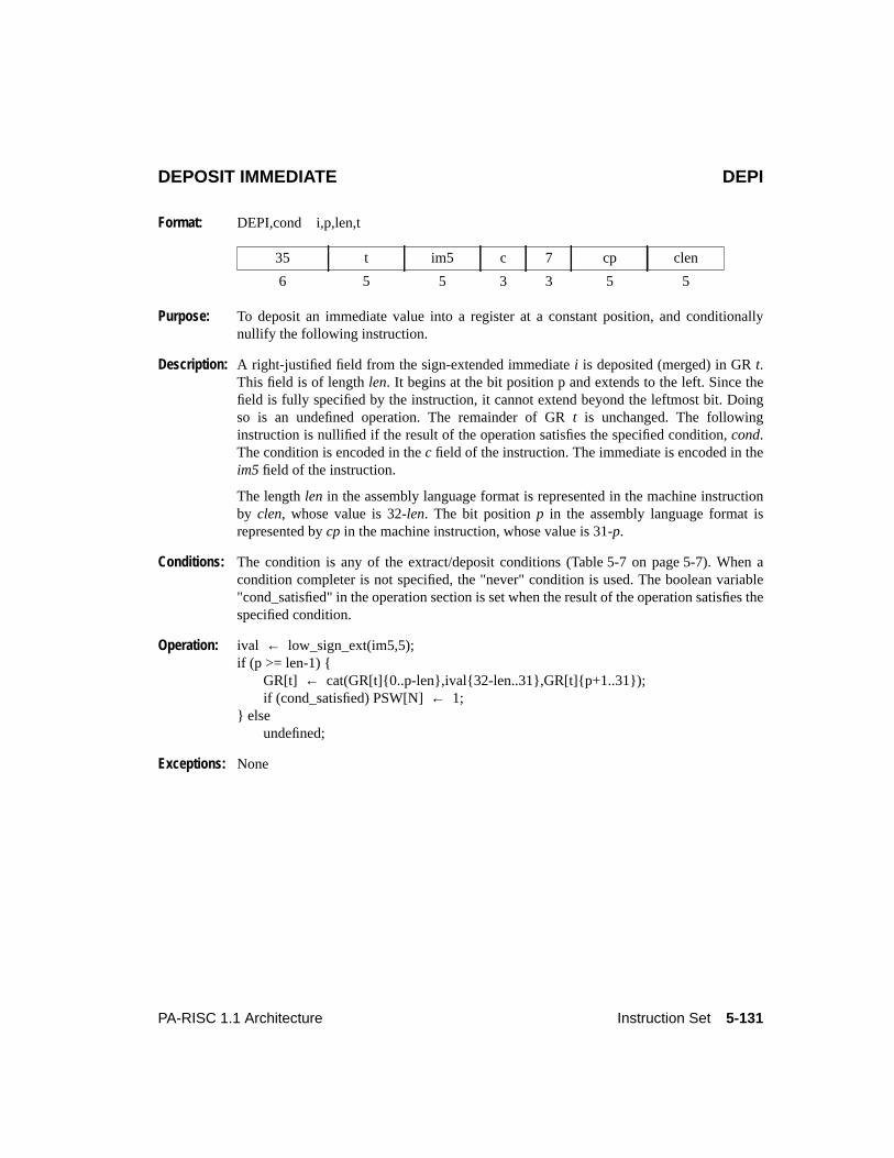
5-131PA-RISC 1.1 Architecture Instruction Set
DEPOSIT IMMEDIATE DEPI
Format: DEPI,cond i,p,len,t
Purpose: To deposit an immediate value into a register at a constant position, and conditionallynullify the following instruction.
Description: A right-justified field from the sign-extended immediatei is deposited (merged) in GRt.This field is of lengthlen. It begins at the bit position p and extends to the left. Since thefield is fully specified by the instruction, it cannot extend beyond the leftmost bit. Doingso is an undefined operation. The remainder of GRt is unchanged. The followinginstruction is nullified if the result of the operation satisfies the specified condition,cond.The condition is encoded in thec field of the instruction. The immediate is encoded in theim5 field of the instruction.
The lengthlen in the assembly language format is represented in the machine instructionby clen, whose value is 32-len. The bit positionp in the assembly language format isrepresented bycp in the machine instruction, whose value is 31-p.
Conditions: The condition is any of the extract/deposit conditions (Table 5-7 on page 5-7). When acondition completer is not specified, the "never" condition is used. The boolean variable"cond_satisfied" in the operation section is set when the result of the operation satisfies thespecified condition.
Operation: ival ← low_sign_ext(im5,5);if (p >= len-1) {
GR[t] ← cat(GR[t]{0..p-len},ival{32-len..31},GR[t]{p+1..31});if (cond_satisfied) PSW[N]← 1;
} elseundefined;
Exceptions: None
35 t im5 c 7 cp clen
6 5 5 3 3 5 5
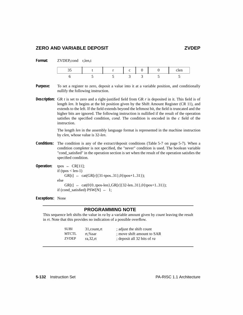
5-132 Instruction Set PA-RISC 1.1 Architecture
ZERO AND VARIABLE DEPOSIT ZVDEP
Format: ZVDEP,cond r,len,t
Purpose: To set a register to zero, deposit a value into it at a variable position, and conditionallynullify the following instruction.
Description: GR t is set to zero and a right-justified field from GRr is deposited in it. This field is oflength len. It begins at the bit position given by the Shift Amount Register (CR 11), andextends to the left. If the field extends beyond the leftmost bit, the field is truncated and thehigher bits are ignored. The following instruction is nullified if the result of the operationsatisfies the specified condition,cond. The condition is encoded in thec field of theinstruction.
The lengthlen in the assembly language format is represented in the machine instructionby clen, whose value is 32-len.
Conditions: The condition is any of the extract/deposit conditions (Table 5-7 on page 5-7). When acondition completer is not specified, the "never" condition is used. The boolean variable"cond_satisfied" in the operation section is set when the result of the operation satisfies thespecified condition.
Operation: tpos ← CR[11];if (tpos < len-1)
GR[t] ← cat(GR[r]{31-tpos..31},0{tpos+1..31});else
GR[t] ← cat(0{0..tpos-len},GR[r]{32-len..31},0{tpos+1..31});if (cond_satisfied) PSW[N]← 1;
Exceptions: None
PROGRAMMING NOTEThis sequence left shifts the value inra by a variable amount given bycount leaving the resultin rt. Note that this provides no indication of a possible overflow.
35 t r c 0 0 clen
6 5 5 3 3 5 5
SUBI 31,count,rt ; adjust the shift countMTCTL rt,%sar ; move shift amount to SARZVDEP ra,32,rt ; deposit all 32 bits ofra
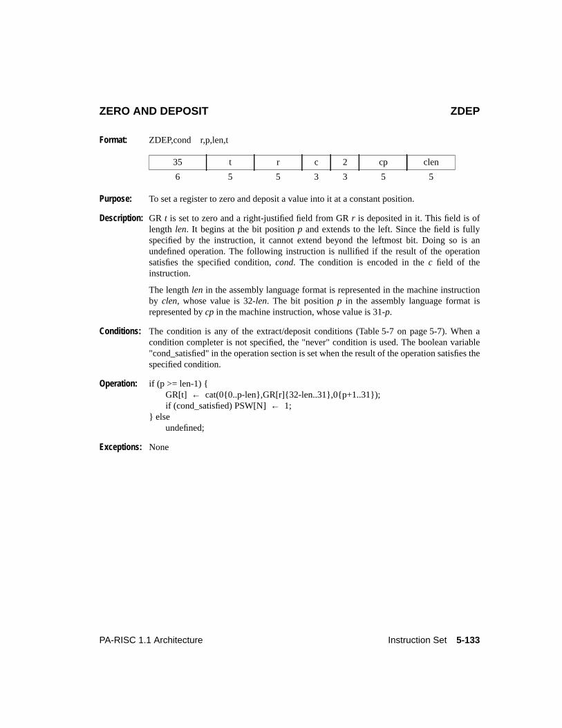
5-133PA-RISC 1.1 Architecture Instruction Set
ZERO AND DEPOSIT ZDEP
Format: ZDEP,cond r,p,len,t
Purpose: To set a register to zero and deposit a value into it at a constant position.
Description: GR t is set to zero and a right-justified field from GRr is deposited in it. This field is oflength len. It begins at the bit positionp and extends to the left. Since the field is fullyspecified by the instruction, it cannot extend beyond the leftmost bit. Doing so is anundefined operation. The following instruction is nullified if the result of the operationsatisfies the specified condition,cond. The condition is encoded in thec field of theinstruction.
The lengthlen in the assembly language format is represented in the machine instructionby clen, whose value is 32-len. The bit positionp in the assembly language format isrepresented bycp in the machine instruction, whose value is 31-p.
Conditions: The condition is any of the extract/deposit conditions (Table 5-7 on page 5-7). When acondition completer is not specified, the "never" condition is used. The boolean variable"cond_satisfied" in the operation section is set when the result of the operation satisfies thespecified condition.
Operation: if (p >= len-1) {GR[t] ← cat(0{0..p-len},GR[r]{32-len..31},0{p+1..31});if (cond_satisfied) PSW[N]← 1;
} elseundefined;
Exceptions: None
35 t r c 2 cp clen
6 5 5 3 3 5 5
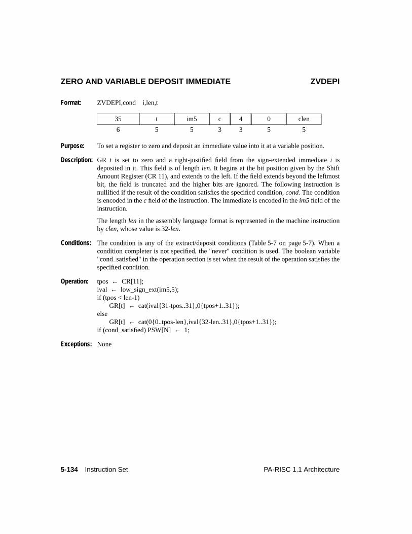
5-134 Instruction Set PA-RISC 1.1 Architecture
ZERO AND VARIABLE DEPOSIT IMMEDIATE ZVDEPI
Format: ZVDEPI,cond i,len,t
Purpose: To set a register to zero and deposit an immediate value into it at a variable position.
Description: GR t is set to zero and a right-justified field from the sign-extended immediatei isdeposited in it. This field is of lengthlen. It begins at the bit position given by the ShiftAmount Register (CR 11), and extends to the left. If the field extends beyond the leftmostbit, the field is truncated and the higher bits are ignored. The following instruction isnullified if the result of the condition satisfies the specified condition,cond. The conditionis encoded in thec field of the instruction. The immediate is encoded in theim5 field of theinstruction.
The lengthlen in the assembly language format is represented in the machine instructionby clen, whose value is 32-len.
Conditions: The condition is any of the extract/deposit conditions (Table 5-7 on page 5-7). When acondition completer is not specified, the "never" condition is used. The boolean variable"cond_satisfied" in the operation section is set when the result of the operation satisfies thespecified condition.
Operation: tpos ← CR[11];ival ← low_sign_ext(im5,5);if (tpos < len-1)
GR[t] ← cat(ival{31-tpos..31},0{tpos+1..31});else
GR[t] ← cat(0{0..tpos-len},ival{32-len..31},0{tpos+1..31});if (cond_satisfied) PSW[N]← 1;
Exceptions: None
35 t im5 c 4 0 clen
6 5 5 3 3 5 5
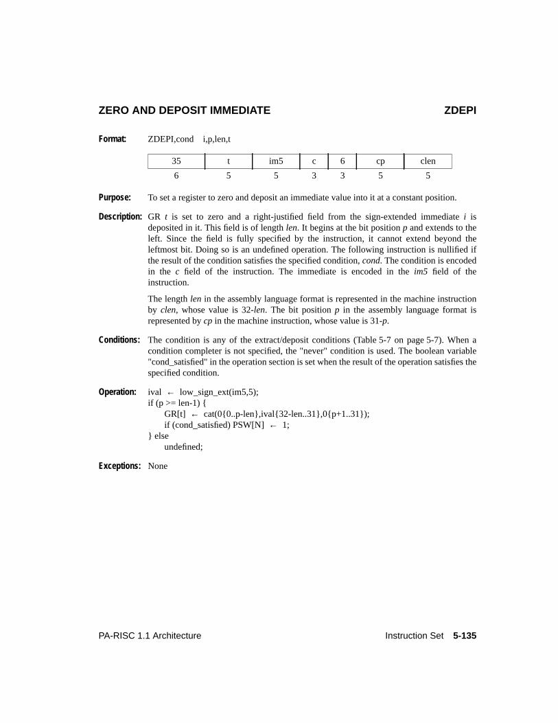
5-135PA-RISC 1.1 Architecture Instruction Set
ZERO AND DEPOSIT IMMEDIATE ZDEPI
Format: ZDEPI,cond i,p,len,t
Purpose: To set a register to zero and deposit an immediate value into it at a constant position.
Description: GR t is set to zero and a right-justified field from the sign-extended immediatei isdeposited in it. This field is of lengthlen. It begins at the bit positionp and extends to theleft. Since the field is fully specified by the instruction, it cannot extend beyond theleftmost bit. Doing so is an undefined operation. The following instruction is nullified ifthe result of the condition satisfies the specified condition,cond. The condition is encodedin the c field of the instruction. The immediate is encoded in theim5 field of theinstruction.
The lengthlen in the assembly language format is represented in the machine instructionby clen, whose value is 32-len. The bit positionp in the assembly language format isrepresented bycp in the machine instruction, whose value is 31-p.
Conditions: The condition is any of the extract/deposit conditions (Table 5-7 on page 5-7). When acondition completer is not specified, the "never" condition is used. The boolean variable"cond_satisfied" in the operation section is set when the result of the operation satisfies thespecified condition.
Operation: ival ← low_sign_ext(im5,5);if (p >= len-1) {
GR[t] ← cat(0{0..p-len},ival{32-len..31},0{p+1..31});if (cond_satisfied) PSW[N]← 1;
} elseundefined;
Exceptions: None
35 t im5 c 6 cp clen
6 5 5 3 3 5 5
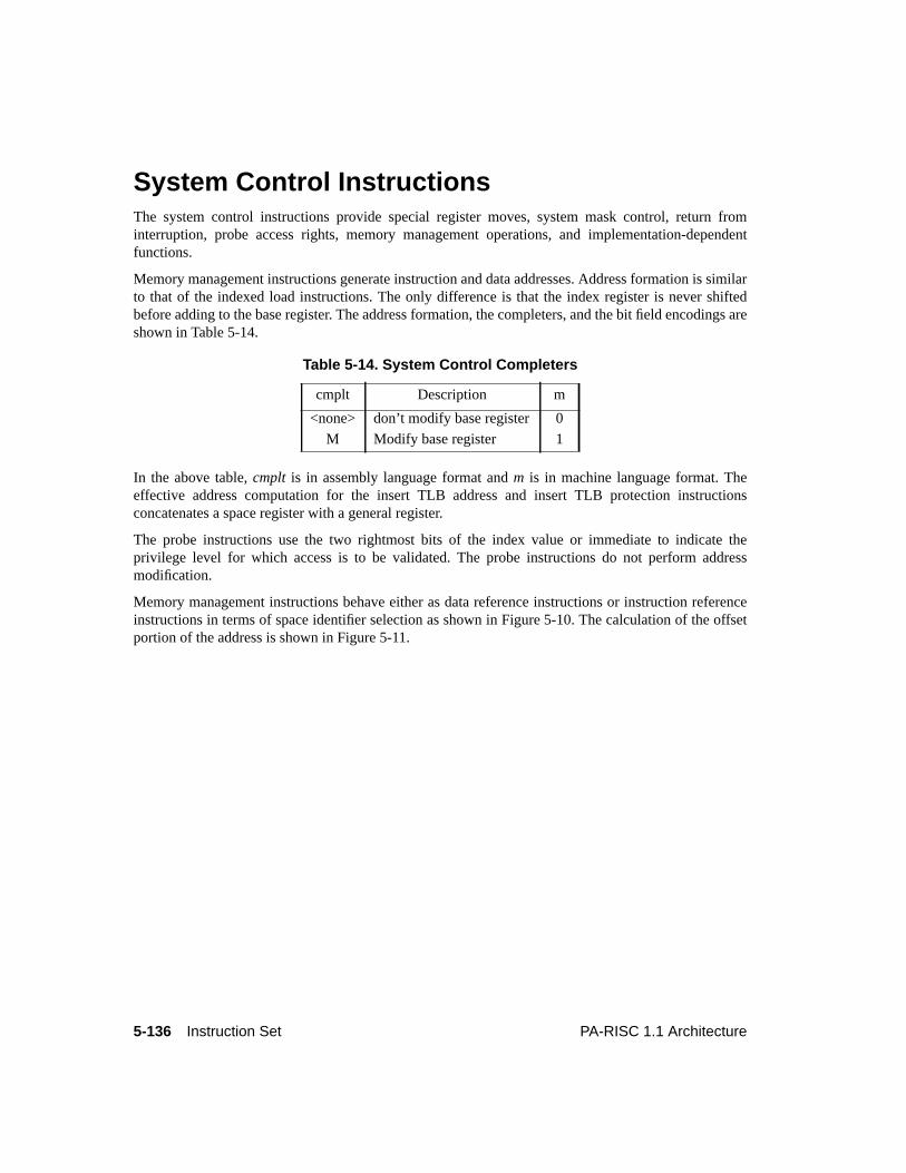
5-136 Instruction Set PA-RISC 1.1 Architecture
5Instruction Set
System Control InstructionsThe system control instructions provide special register moves, system mask control, return frominterruption, probe access rights, memory management operations, and implementation-dependentfunctions.
Memory management instructions generate instruction and data addresses. Address formation is similarto that of the indexed load instructions. The only difference is that the index register is never shiftedbefore adding to the base register. The address formation, the completers, and the bit field encodings areshown in Table 5-14.
In the above table,cmplt is in assembly language format andm is in machine language format. Theeffective address computation for the insert TLB address and insert TLB protection instructionsconcatenates a space register with a general register.
The probe instructions use the two rightmost bits of the index value or immediate to indicate theprivilege level for which access is to be validated. The probe instructions do not perform addressmodification.
Memory management instructions behave either as data reference instructions or instruction referenceinstructions in terms of space identifier selection as shown in Figure 5-10. The calculation of the offsetportion of the address is shown in Figure 5-11.
Table 5-14. System Control Completers
cmplt Description m
<none> don’t modify base register 0
M Modify base register 1
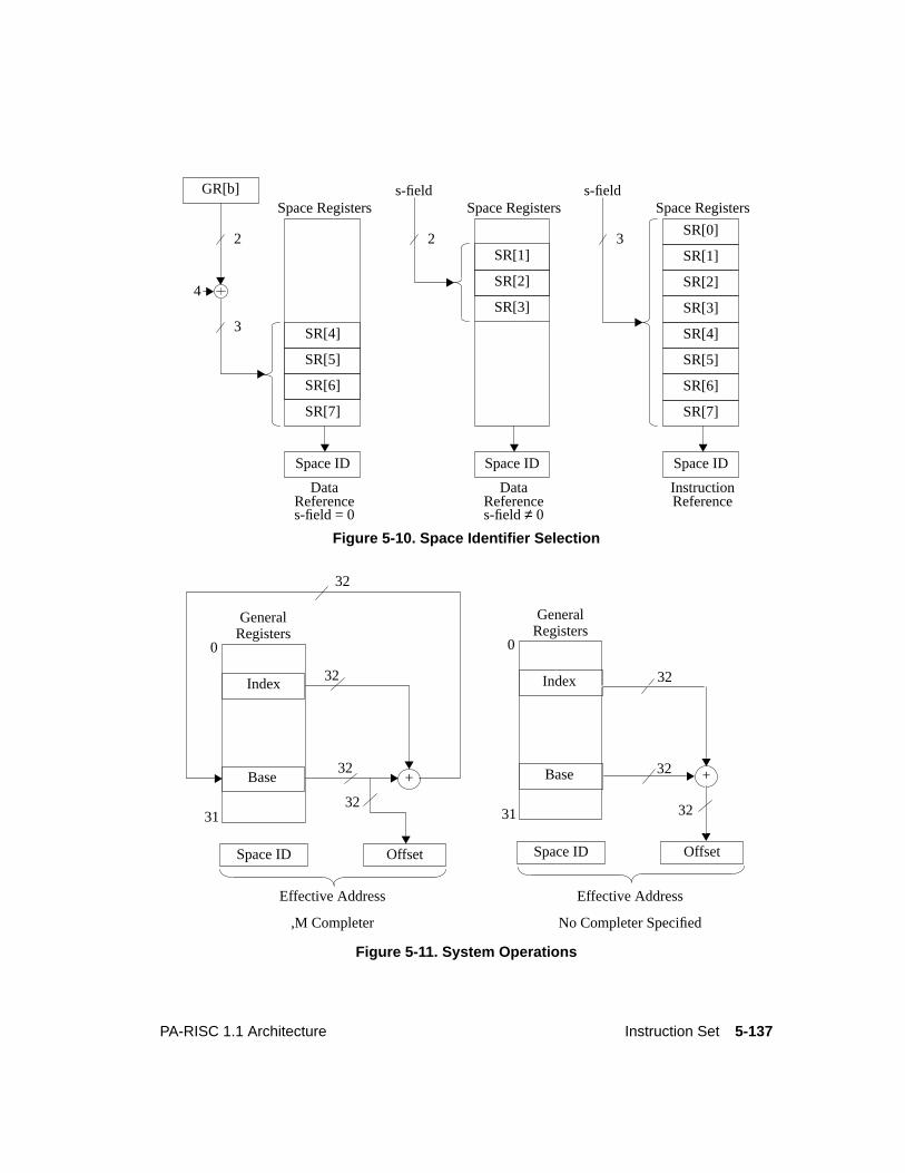
5-137PA-RISC 1.1 Architecture Instruction Set
Figure 5-10. Space Identifier Selection
Figure 5-11. System Operations
SR[1]
SR[2]
SR[3]
Space Registerss-field
Space ID
DataReferences-field≠ 0
SR[0]
SR[1]
SR[2]
SR[3]
SR[4]
SR[5]
SR[6]
SR[7]
SR[4]
SR[5]
SR[6]
SR[7]
Space ID
Space Registers
DataReference
2
s-field = 0
4
Space ID
InstructionReference
s-field
3
2 3
Space RegistersGR[b]
0
31
Base
GeneralRegisters
32+
32
32
Index
Space ID Offset
Effective Address
,M Completer
0
31
Base
GeneralRegisters
+
32Index
Space ID Offset
3232
Effective Address
No Completer Specified
32
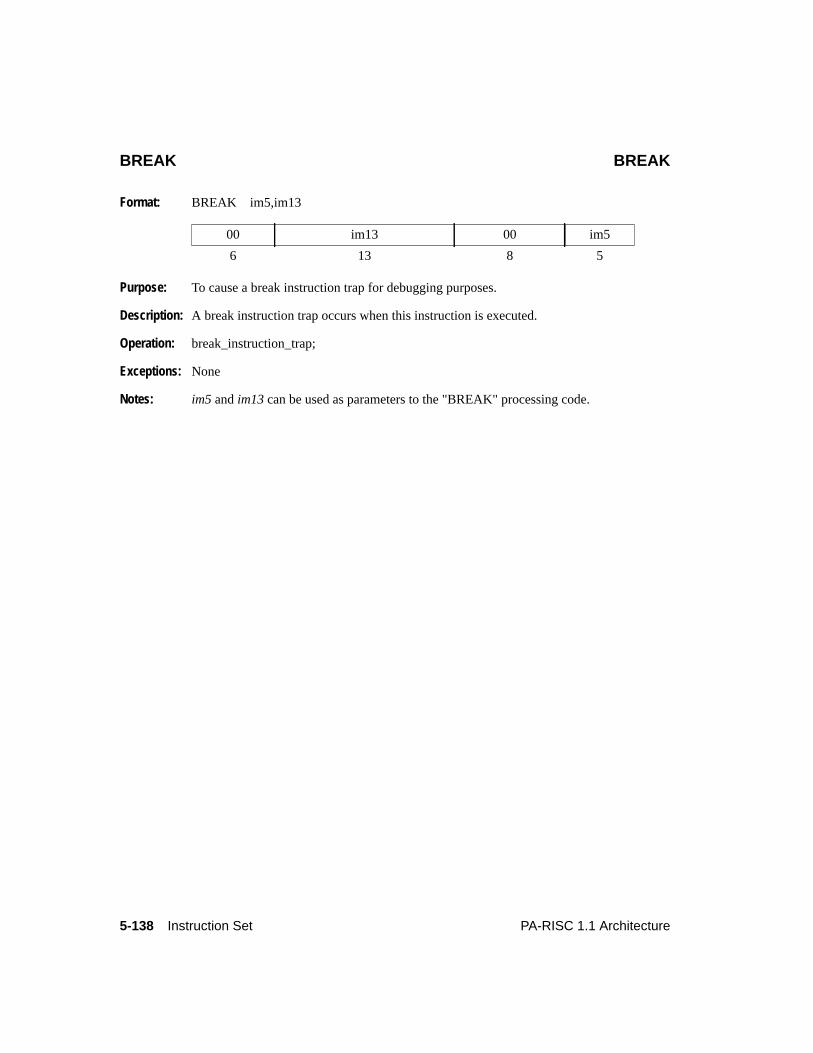
5-138 Instruction Set PA-RISC 1.1 Architecture
BREAK BREAK
Format: BREAK im5,im13
Purpose: To cause a break instruction trap for debugging purposes.
Description: A break instruction trap occurs when this instruction is executed.
Operation: break_instruction_trap;
Exceptions: None
Notes: im5 andim13 can be used as parameters to the "BREAK" processing code.
00 im13 00 im5
6 13 8 5
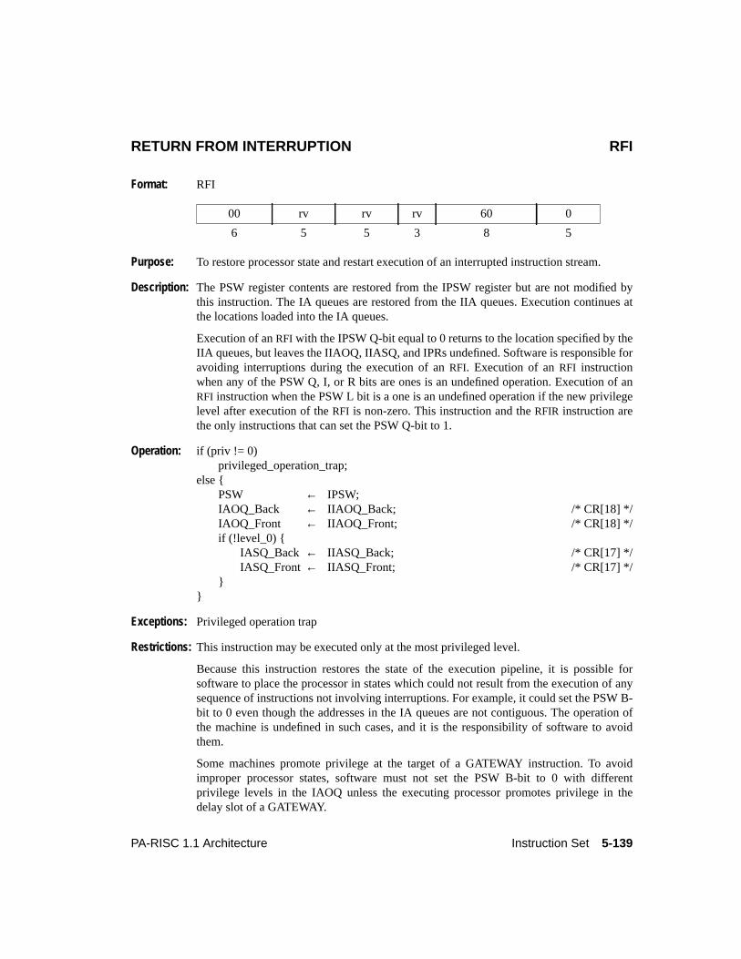
5-139PA-RISC 1.1 Architecture Instruction Set
RETURN FROM INTERRUPTION RFI
Format: RFI
Purpose: To restore processor state and restart execution of an interrupted instruction stream.
Description: The PSW register contents are restored from the IPSW register but are not modified bythis instruction. The IA queues are restored from the IIA queues. Execution continues atthe locations loaded into the IA queues.
Execution of anRFI with the IPSW Q-bit equal to 0 returns to the location specified by theIIA queues, but leaves the IIAOQ, IIASQ, and IPRs undefined. Software is responsible foravoiding interruptions during the execution of anRFI. Execution of anRFI instructionwhen any of the PSW Q, I, or R bits are ones is an undefined operation. Execution of anRFI instruction when the PSW L bit is a one is an undefined operation if the new privilegelevel after execution of theRFI is non-zero. This instruction and theRFIR instruction arethe only instructions that can set the PSW Q-bit to 1.
Operation: if (priv != 0)privileged_operation_trap;
else {PSW ← IPSW;IAOQ_Back ← IIAOQ_Back; /* CR[18] */IAOQ_Front ← IIAOQ_Front; /* CR[18] */if (!level_0) {
IASQ_Back ← IIASQ_Back; /* CR[17] */IASQ_Front← IIASQ_Front; /* CR[17] */
}}
Exceptions: Privileged operation trap
Restrictions: This instruction may be executed only at the most privileged level.
Because this instruction restores the state of the execution pipeline, it is possible forsoftware to place the processor in states which could not result from the execution of anysequence of instructions not involving interruptions. For example, it could set the PSW B-bit to 0 even though the addresses in the IA queues are not contiguous. The operation ofthe machine is undefined in such cases, and it is the responsibility of software to avoidthem.
Some machines promote privilege at the target of a GATEWAY instruction. To avoidimproper processor states, software must not set the PSW B-bit to 0 with differentprivilege levels in the IAOQ unless the executing processor promotes privilege in thedelay slot of a GATEWAY.
00 rv rv rv 60 0
6 5 5 3 8 5

5-140 Instruction Set PA-RISC 1.1 Architecture
Notes: When this instruction returns to an instruction which executes at a lower privilege level, alower-privilege transfer trap is not taken.
Level 0: This instruction executes as usual except that the IASQ is nonexistent and updating it hasno effect.
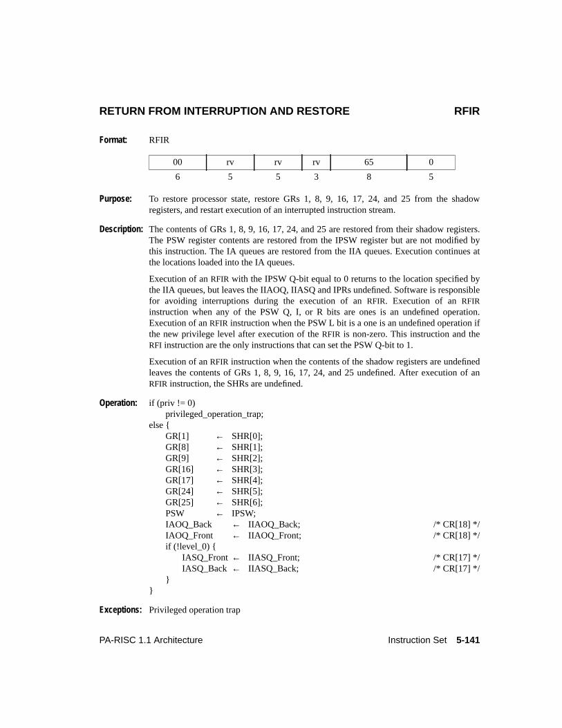
5-141PA-RISC 1.1 Architecture Instruction Set
RETURN FROM INTERRUPTION AND RESTORE RFIR
Format: RFIR
Purpose: To restore processor state, restore GRs 1, 8, 9, 16, 17, 24, and 25 from the shadowregisters, and restart execution of an interrupted instruction stream.
Description: The contents of GRs 1, 8, 9, 16, 17, 24, and 25 are restored from their shadow registers.The PSW register contents are restored from the IPSW register but are not modified bythis instruction. The IA queues are restored from the IIA queues. Execution continues atthe locations loaded into the IA queues.
Execution of anRFIR with the IPSW Q-bit equal to 0 returns to the location specified bythe IIA queues, but leaves the IIAOQ, IIASQ and IPRs undefined. Software is responsiblefor avoiding interruptions during the execution of anRFIR. Execution of anRFIRinstruction when any of the PSW Q, I, or R bits are ones is an undefined operation.Execution of anRFIR instruction when the PSW L bit is a one is an undefined operation ifthe new privilege level after execution of theRFIR is non-zero. This instruction and theRFI instruction are the only instructions that can set the PSW Q-bit to 1.
Execution of anRFIR instruction when the contents of the shadow registers are undefinedleaves the contents of GRs 1, 8, 9, 16, 17, 24, and 25 undefined. After execution of anRFIR instruction, the SHRs are undefined.
Operation: if (priv != 0)privileged_operation_trap;
else {GR[1] ← SHR[0];GR[8] ← SHR[1];GR[9] ← SHR[2];GR[16] ← SHR[3];GR[17] ← SHR[4];GR[24] ← SHR[5];GR[25] ← SHR[6];PSW ← IPSW;IAOQ_Back ← IIAOQ_Back; /* CR[18] */IAOQ_Front ← IIAOQ_Front; /* CR[18] */if (!level_0) {
IASQ_Front← IIASQ_Front; /* CR[17] */IASQ_Back ← IIASQ_Back; /* CR[17] */
}}
Exceptions: Privileged operation trap
00 rv rv rv 65 0
6 5 5 3 8 5
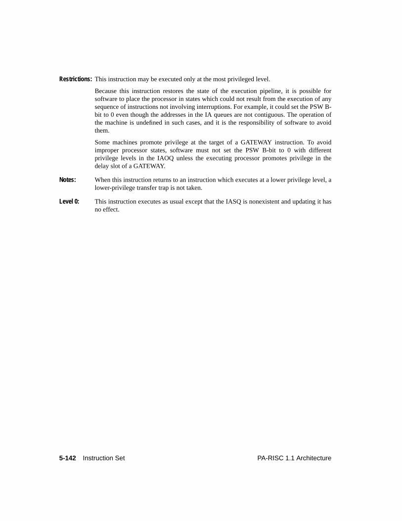
5-142 Instruction Set PA-RISC 1.1 Architecture
Restrictions: This instruction may be executed only at the most privileged level.
Because this instruction restores the state of the execution pipeline, it is possible forsoftware to place the processor in states which could not result from the execution of anysequence of instructions not involving interruptions. For example, it could set the PSW B-bit to 0 even though the addresses in the IA queues are not contiguous. The operation ofthe machine is undefined in such cases, and it is the responsibility of software to avoidthem.
Some machines promote privilege at the target of a GATEWAY instruction. To avoidimproper processor states, software must not set the PSW B-bit to 0 with differentprivilege levels in the IAOQ unless the executing processor promotes privilege in thedelay slot of a GATEWAY.
Notes: When this instruction returns to an instruction which executes at a lower privilege level, alower-privilege transfer trap is not taken.
Level 0: This instruction executes as usual except that the IASQ is nonexistent and updating it hasno effect.
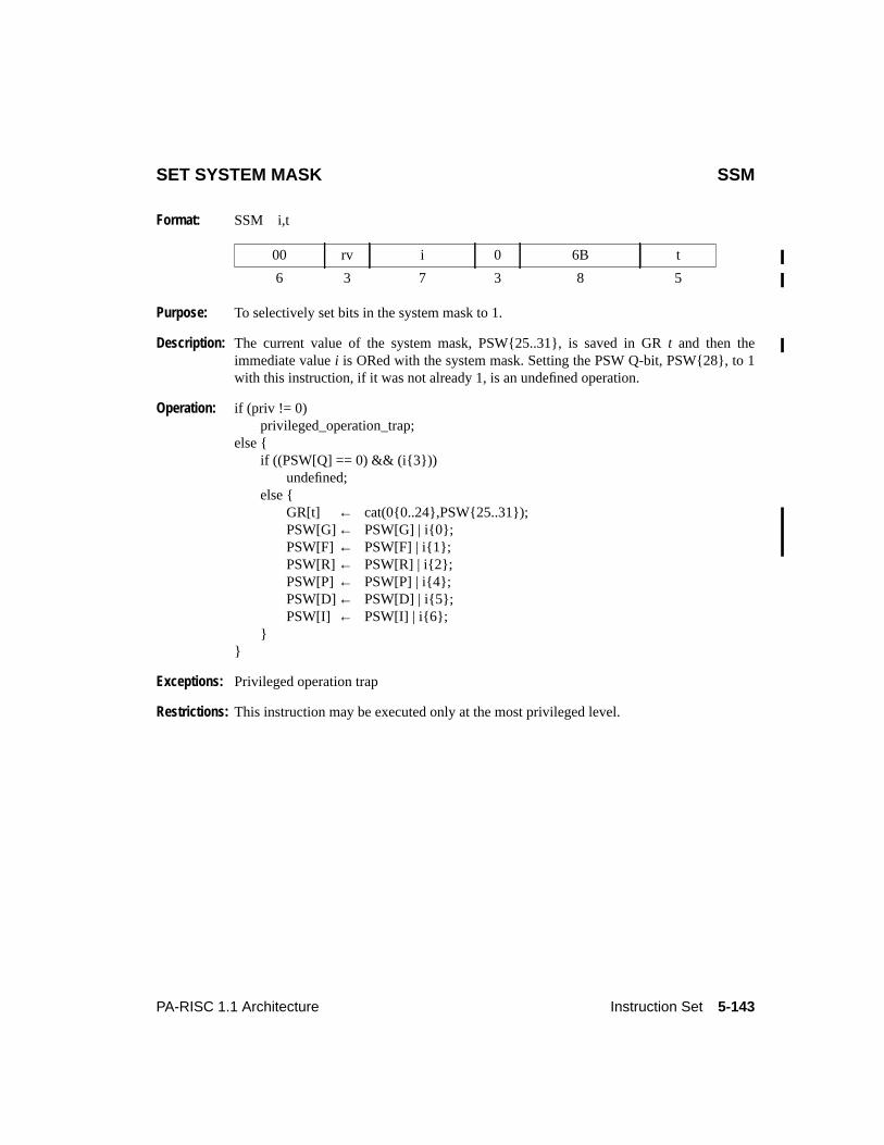
5-143PA-RISC 1.1 Architecture Instruction Set
SET SYSTEM MASK SSM
Format: SSM i,t
Purpose: To selectively set bits in the system mask to 1.
Description: The current value of the system mask, PSW{25..31}, is saved in GRt and then theimmediate valuei is ORed with the system mask. Setting the PSW Q-bit, PSW{28}, to 1with this instruction, if it was not already 1, is an undefined operation.
Operation: if (priv != 0)privileged_operation_trap;
else {if ((PSW[Q] == 0) && (i{3}))
undefined;else {
GR[t] ← cat(0{0..24},PSW{25..31});PSW[G]← PSW[G] | i{0};PSW[F] ← PSW[F] | i{1};PSW[R]← PSW[R] | i{2};PSW[P]← PSW[P] | i{4};PSW[D]← PSW[D] | i{5};PSW[I] ← PSW[I] | i{6};
}}
Exceptions: Privileged operation trap
Restrictions: This instruction may be executed only at the most privileged level.
00 rv i 0 6B t
6 3 7 3 8 5
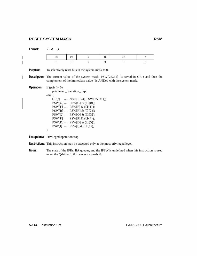
5-144 Instruction Set PA-RISC 1.1 Architecture
RESET SYSTEM MASK RSM
Format: RSM i,t
Purpose: To selectively reset bits in the system mask to 0.
Description: The current value of the system mask, PSW{25..31}, is saved in GRt and then thecomplement of the immediate valuei is ANDed with the system mask.
Operation: if (priv != 0)privileged_operation_trap;
else {GR[t] ← cat(0{0..24},PSW{25..31});PSW[G]← PSW[G] & (∼i{0});PSW[F] ← PSW[F] & (∼i{1});PSW[R]← PSW[R] & (∼i{2});PSW[Q]← PSW[Q] & (∼i{3});PSW[P]← PSW[P] & (∼i{4});PSW[D]← PSW[D] & (∼i{5});PSW[I] ← PSW[I] & (∼i{6});
}
Exceptions: Privileged operation trap
Restrictions: This instruction may be executed only at the most privileged level.
Notes: The state of the IPRs, IIA queues, and the IPSW is undefined when this instruction is usedto set the Q-bit to 0, if it was not already 0.
00 rv i 0 73 t
6 3 7 3 8 5
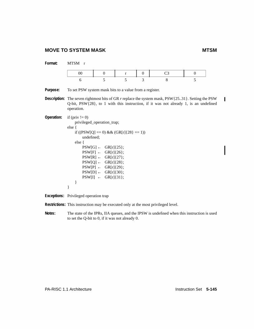
5-145PA-RISC 1.1 Architecture Instruction Set
MOVE TO SYSTEM MASK MTSM
Format: MTSM r
Purpose: To set PSW system mask bits to a value from a register.
Description: The seven rightmost bits of GRr replace the system mask, PSW{25..31}. Setting the PSWQ-bit, PSW{28}, to 1 with this instruction, if it was not already 1, is an undefinedoperation.
Operation: if (priv != 0)privileged_operation_trap;
else {if ((PSW[Q] == 0) && (GR[r]{28} == 1))
undefined;else {
PSW[G]← GR[r]{25};PSW[F] ← GR[r]{26};PSW[R]← GR[r]{27};PSW[Q]← GR[r]{28};PSW[P]← GR[r]{29};PSW[D]← GR[r]{30};PSW[I] ← GR[r]{31};
}}
Exceptions: Privileged operation trap
Restrictions: This instruction may be executed only at the most privileged level.
Notes: The state of the IPRs, IIA queues, and the IPSW is undefined when this instruction is usedto set the Q-bit to 0, if it was not already 0.
00 0 r 0 C3 0
6 5 5 3 8 5
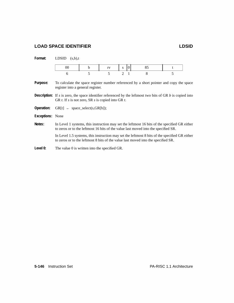
5-146 Instruction Set PA-RISC 1.1 Architecture
LOAD SPACE IDENTIFIER LDSID
Format: LDSID (s,b),t
Purpose: To calculate the space register number referenced by a short pointer and copy the spaceregister into a general register.
Description: If s is zero, the space identifier referenced by the leftmost two bits of GRb is copied intoGR t. If s is not zero, SRs is copied into GRt.
Operation: GR[t] ← space_select(s,GR[b]);
Exceptions: None
Notes: In Level 1 systems, this instruction may set the leftmost 16 bits of the specified GR eitherto zeros or to the leftmost 16 bits of the value last moved into the specified SR.
In Level 1.5 systems, this instruction may set the leftmost 8 bits of the specified GR eitherto zeros or to the leftmost 8 bits of the value last moved into the specified SR.
Level 0: The value 0 is written into the specified GR.
00 b rv s 0 85 t
6 5 5 2 1 8 5
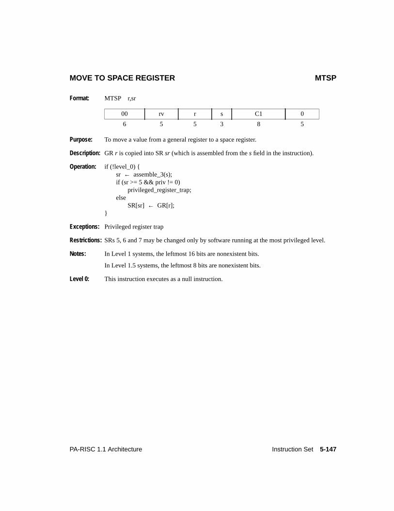
5-147PA-RISC 1.1 Architecture Instruction Set
MOVE TO SPACE REGISTER MTSP
Format: MTSP r,sr
Purpose: To move a value from a general register to a space register.
Description: GR r is copied into SRsr (which is assembled from thes field in the instruction).
Operation: if (!level_0) {sr ← assemble_3(s);if (sr >= 5 && priv != 0)
privileged_register_trap;else
SR[sr] ← GR[r];}
Exceptions: Privileged register trap
Restrictions: SRs 5, 6 and 7 may be changed only by software running at the most privileged level.
Notes: In Level 1 systems, the leftmost 16 bits are nonexistent bits.
In Level 1.5 systems, the leftmost 8 bits are nonexistent bits.
Level 0: This instruction executes as a null instruction.
00 rv r s C1 0
6 5 5 3 8 5
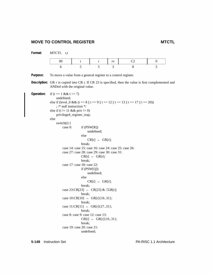
5-148 Instruction Set PA-RISC 1.1 Architecture
MOVE TO CONTROL REGISTER MTCTL
Format: MTCTL r,t
Purpose: To move a value from a general register to a control register.
Description: GR r is copied into CRt. If CR 23 is specified, then the value is first complemented andANDed with the original value.
Operation: if (t >= 1 && t <= 7)undefined;
else if (level_0 && (t == 8 || t == 9 || t == 12 || t == 13 || t == 17 || t == 20)); /* null instruction */
else if (t != 11 && priv != 0)privileged_register_trap;
elseswitch(t) {
case 0: if (PSW[R])undefined;
elseCR[t] ← GR[r];
break;case 14: case 15: case 16: case 24: case 25: case 26:case 27: case 28: case 29: case 30: case 31:
CR[t] ← GR[r];break;
case 17: case 18: case 22:if (PSW[Q])
undefined;else
CR[t] ← GR[r];break;
case 23:CR[23]← CR[23] & ∼GR[r];break;
case 10:CR[10]← GR[r]{16..31};break;
case 11:CR[11]← GR[r]{27..31};break;
case 8: case 9: case 12: case 13:CR[t] ← GR[r]{16..31};break;
case 19: case 20: case 21:undefined;
00 t r rv C2 0
6 5 5 3 8 5
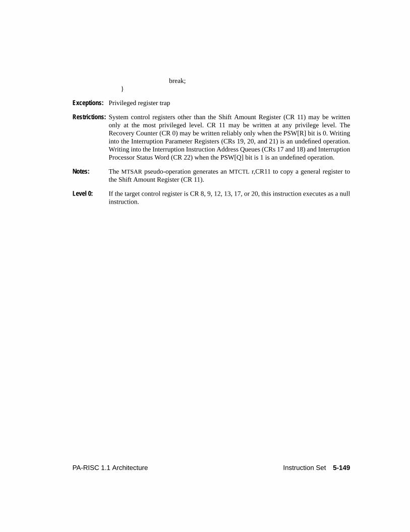
5-149PA-RISC 1.1 Architecture Instruction Set
break;}
Exceptions: Privileged register trap
Restrictions: System control registers other than the Shift Amount Register (CR 11) may be writtenonly at the most privileged level. CR 11 may be written at any privilege level. TheRecovery Counter (CR 0) may be written reliably only when the PSW[R] bit is 0. Writinginto the Interruption Parameter Registers (CRs 19, 20, and 21) is an undefined operation.Writing into the Interruption Instruction Address Queues (CRs 17 and 18) and InterruptionProcessor Status Word (CR 22) when the PSW[Q] bit is 1 is an undefined operation.
Notes: The MTSAR pseudo-operation generates anMTCTL r,CR11 to copy a general register tothe Shift Amount Register (CR 11).
Level 0: If the target control register is CR 8, 9, 12, 13, 17, or 20, this instruction executes as a nullinstruction.
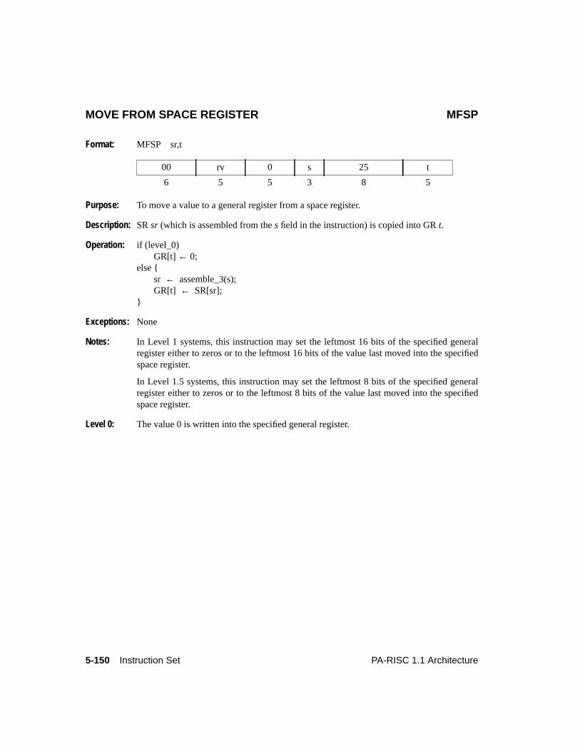
5-150 Instruction Set PA-RISC 1.1 Architecture
MOVE FROM SPACE REGISTER MFSP
Format: MFSP sr,t
Purpose: To move a value to a general register from a space register.
Description: SRsr (which is assembled from thes field in the instruction) is copied into GRt.
Operation: if (level_0)GR[t] ← 0;
else {sr ← assemble_3(s);GR[t] ← SR[sr];
}
Exceptions: None
Notes: In Level 1 systems, this instruction may set the leftmost 16 bits of the specified generalregister either to zeros or to the leftmost 16 bits of the value last moved into the specifiedspace register.
In Level 1.5 systems, this instruction may set the leftmost 8 bits of the specified generalregister either to zeros or to the leftmost 8 bits of the value last moved into the specifiedspace register.
Level 0: The value 0 is written into the specified general register.
00 rv 0 s 25 t
6 5 5 3 8 5
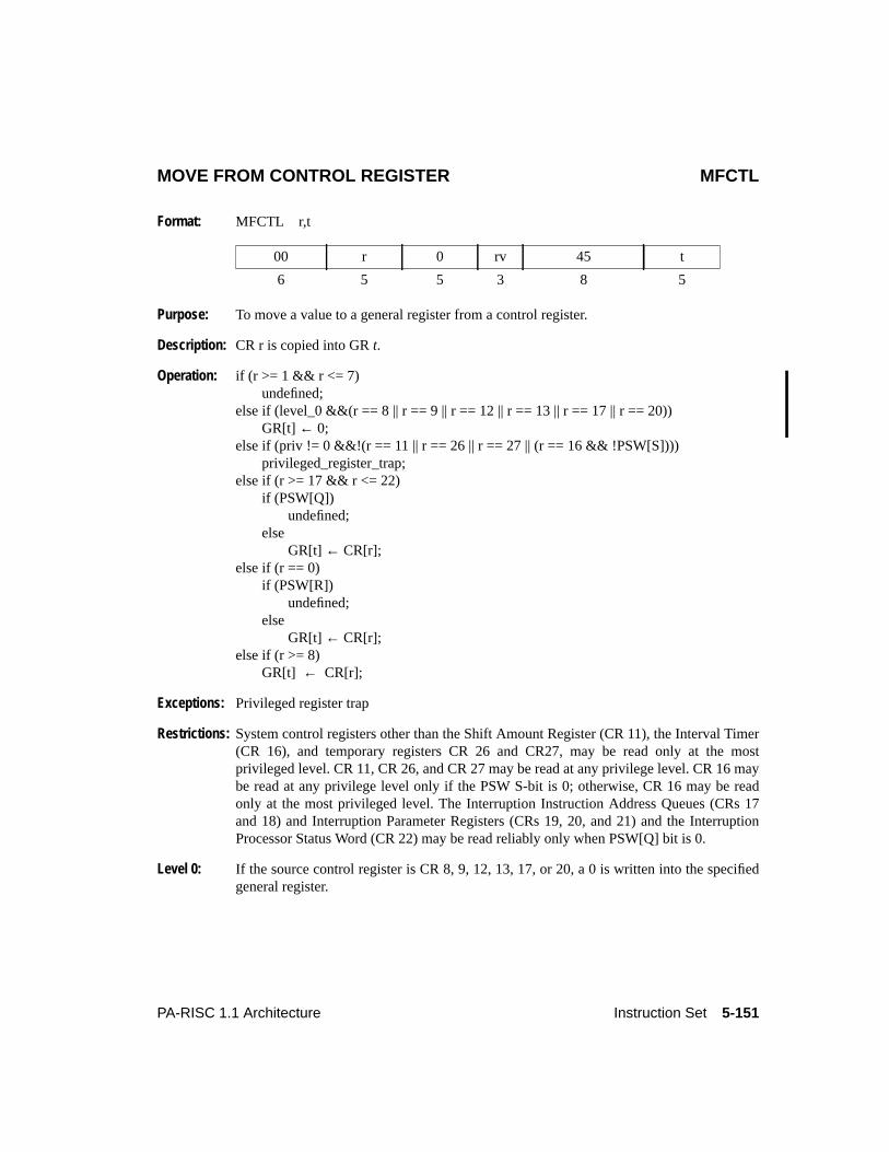
5-151PA-RISC 1.1 Architecture Instruction Set
MOVE FROM CONTROL REGISTER MFCTL
Format: MFCTL r,t
Purpose: To move a value to a general register from a control register.
Description: CR r is copied into GRt.
Operation: if (r >= 1 && r <= 7)undefined;
else if (level_0 &&(r == 8 || r == 9 || r == 12 || r == 13 || r == 17 || r == 20))GR[t] ← 0;
else if (priv != 0 &&!(r == 11 || r == 26 || r == 27 || (r == 16 && !PSW[S])))privileged_register_trap;
else if (r >= 17 && r <= 22)if (PSW[Q])
undefined;else
GR[t] ← CR[r];else if (r == 0)
if (PSW[R])undefined;
elseGR[t] ← CR[r];
else if (r >= 8)GR[t] ← CR[r];
Exceptions: Privileged register trap
Restrictions: System control registers other than the Shift Amount Register (CR 11), the Interval Timer(CR 16), and temporary registers CR 26 and CR27, may be read only at the mostprivileged level. CR 11, CR 26, and CR 27 may be read at any privilege level. CR 16 maybe read at any privilege level only if the PSW S-bit is 0; otherwise, CR 16 may be readonly at the most privileged level. The Interruption Instruction Address Queues (CRs 17and 18) and Interruption Parameter Registers (CRs 19, 20, and 21) and the InterruptionProcessor Status Word (CR 22) may be read reliably only when PSW[Q] bit is 0.
Level 0: If the source control register is CR 8, 9, 12, 13, 17, or 20, a 0 is written into the specifiedgeneral register.
00 r 0 rv 45 t
6 5 5 3 8 5
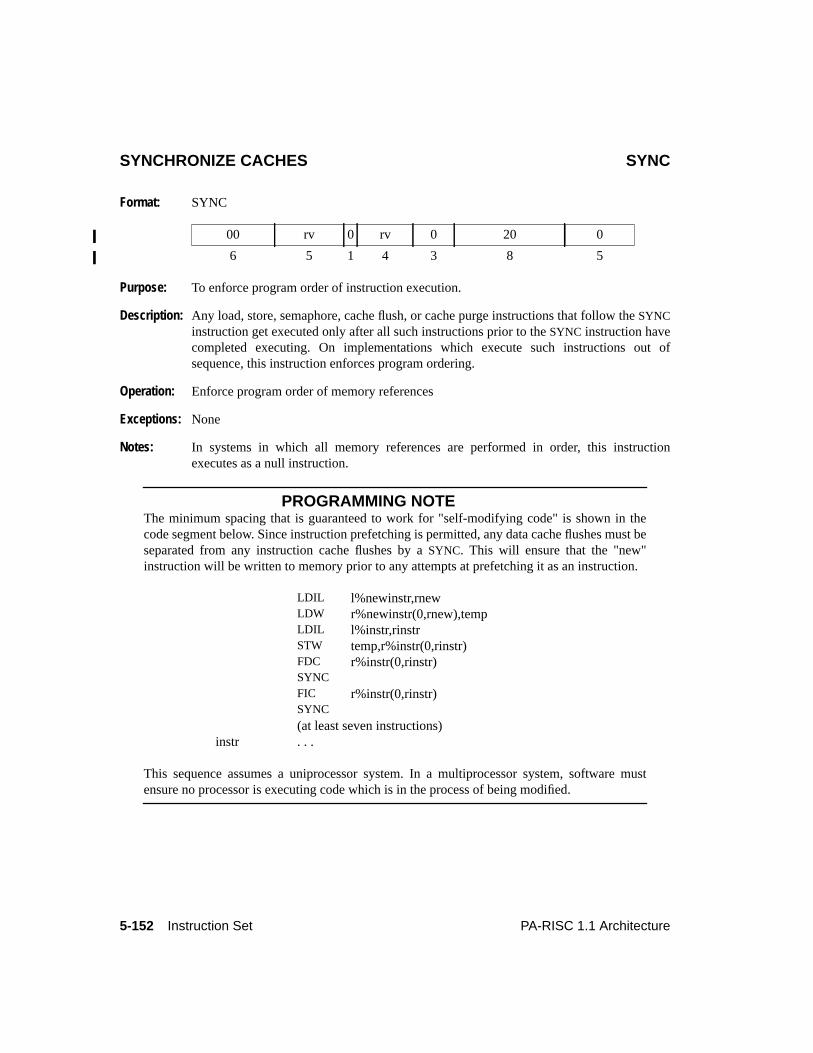
5-152 Instruction Set PA-RISC 1.1 Architecture
SYNCHRONIZE CACHES SYNC
Format: SYNC
Purpose: To enforce program order of instruction execution.
Description: Any load, store, semaphore, cache flush, or cache purge instructions that follow theSYNCinstruction get executed only after all such instructions prior to theSYNC instruction havecompleted executing. On implementations which execute such instructions out ofsequence, this instruction enforces program ordering.
Operation: Enforce program order of memory references
Exceptions: None
Notes: In systems in which all memory references are performed in order, this instructionexecutes as a null instruction.
PROGRAMMING NOTEThe minimum spacing that is guaranteed to work for "self-modifying code" is shown in thecode segment below. Since instruction prefetching is permitted, any data cache flushes must beseparated from any instruction cache flushes by aSYNC. This will ensure that the "new"instruction will be written to memory prior to any attempts at prefetching it as an instruction.
This sequence assumes a uniprocessor system. In a multiprocessor system, software mustensure no processor is executing code which is in the process of being modified.
00 rv 0 rv 0 20 0
6 5 1 4 3 8 5
LDIL l%newinstr,rnewLDW r%newinstr(0,rnew),tempLDIL l%instr,rinstrSTW temp,r%instr(0,rinstr)FDC r%instr(0,rinstr)SYNCFIC r%instr(0,rinstr)SYNC
(at least seven instructions)instr . . .
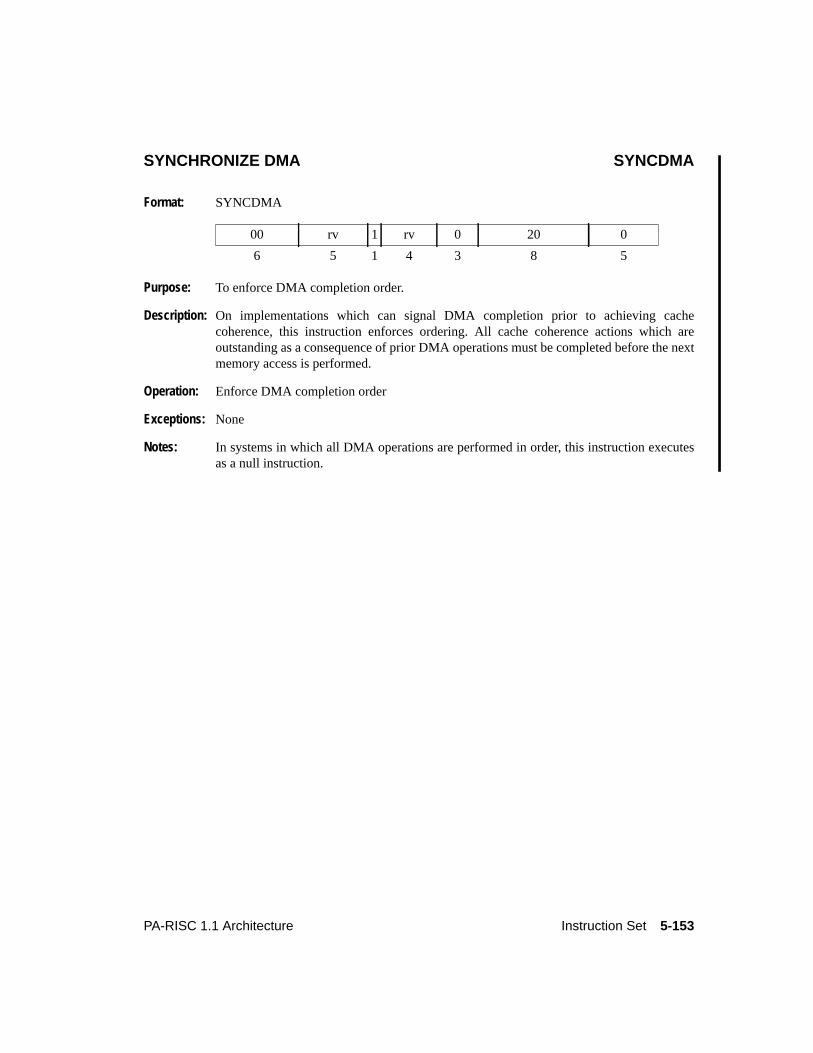
5-153PA-RISC 1.1 Architecture Instruction Set
SYNCHRONIZE DMA SYNCDMA
Format: SYNCDMA
Purpose: To enforce DMA completion order.
Description: On implementations which can signal DMA completion prior to achieving cachecoherence, this instruction enforces ordering. All cache coherence actions which areoutstanding as a consequence of prior DMA operations must be completed before the nextmemory access is performed.
Operation: Enforce DMA completion order
Exceptions: None
Notes: In systems in which all DMA operations are performed in order, this instruction executesas a null instruction.
00 rv 1 rv 0 20 0
6 5 1 4 3 8 5
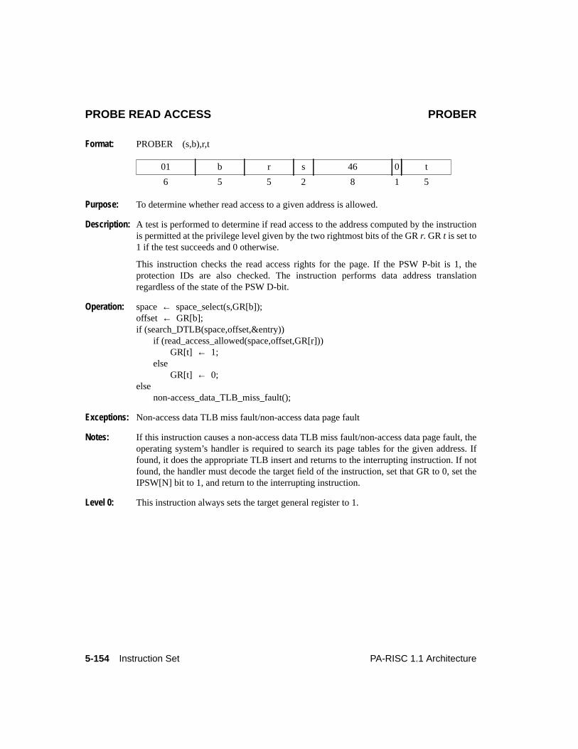
5-154 Instruction Set PA-RISC 1.1 Architecture
PROBE READ ACCESS PROBER
Format: PROBER (s,b),r,t
Purpose: To determine whether read access to a given address is allowed.
Description: A test is performed to determine if read access to the address computed by the instructionis permitted at the privilege level given by the two rightmost bits of the GRr. GRt is set to1 if the test succeeds and 0 otherwise.
This instruction checks the read access rights for the page. If the PSW P-bit is 1, theprotection IDs are also checked. The instruction performs data address translationregardless of the state of the PSW D-bit.
Operation: space← space_select(s,GR[b]);offset ← GR[b];if (search_DTLB(space,offset,&entry))
if (read_access_allowed(space,offset,GR[r]))GR[t] ← 1;
elseGR[t] ← 0;
elsenon-access_data_TLB_miss_fault();
Exceptions: Non-access data TLB miss fault/non-access data page fault
Notes: If this instruction causes a non-access data TLB miss fault/non-access data page fault, theoperating system’s handler is required to search its page tables for the given address. Iffound, it does the appropriate TLB insert and returns to the interrupting instruction. If notfound, the handler must decode the target field of the instruction, set that GR to 0, set theIPSW[N] bit to 1, and return to the interrupting instruction.
Level 0: This instruction always sets the target general register to 1.
01 b r s 46 0 t
6 5 5 2 8 1 5
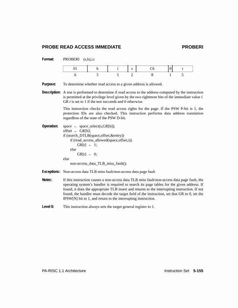
5-155PA-RISC 1.1 Architecture Instruction Set
PROBE READ ACCESS IMMEDIATE PROBERI
Format: PROBERI (s,b),i,t
Purpose: To determine whether read access to a given address is allowed.
Description: A test is performed to determine if read access to the address computed by the instructionis permitted at the privilege level given by the two rightmost bits of the immediate valuei.GR t is set to 1 if the test succeeds and 0 otherwise.
This instruction checks the read access rights for the page. If the PSW P-bit is 1, theprotection IDs are also checked. This instruction performs data address translationregardless of the state of the PSW D-bit.
Operation: space← space_select(s,GR[b]);offset ← GR[b];if (search_DTLB(space,offset,&entry))
if (read_access_allowed(space,offset,i))GR[t] ← 1;
elseGR[t] ← 0;
elsenon-access_data_TLB_miss_fault();
Exceptions: Non-access data TLB miss fault/non-access data page fault
Notes: If this instruction causes a non-access data TLB miss fault/non-access data page fault, theoperating system’s handler is required to search its page tables for the given address. Iffound, it does the appropriate TLB insert and returns to the interrupting instruction. If notfound, the handler must decode the target field of the instruction, set that GR to 0, set theIPSW[N] bit to 1, and return to the interrupting instruction.
Level 0: This instruction always sets the target general register to 1.
01 b i s C6 0 t
6 5 5 2 8 1 5
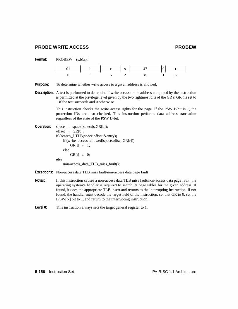
5-156 Instruction Set PA-RISC 1.1 Architecture
PROBE WRITE ACCESS PROBEW
Format: PROBEW (s,b),r,t
Purpose: To determine whether write access to a given address is allowed.
Description: A test is performed to determine if write access to the address computed by the instructionis permitted at the privilege level given by the two rightmost bits of the GRr. GRt is set to1 if the test succeeds and 0 otherwise.
This instruction checks the write access rights for the page. If the PSW P-bit is 1, theprotection IDs are also checked. This instruction performs data address translationregardless of the state of the PSW D-bit.
Operation: space← space_select(s,GR[b]);offset ← GR[b];if (search_DTLB(space,offset,&entry))
if (write_access_allowed(space,offset,GR[r]))GR[t] ← 1;
elseGR[t] ← 0;
elsenon-access_data_TLB_miss_fault();
Exceptions: Non-access data TLB miss fault/non-access data page fault
Notes: If this instruction causes a non-access data TLB miss fault/non-access data page fault, theoperating system’s handler is required to search its page tables for the given address. Iffound, it does the appropriate TLB insert and returns to the interrupting instruction. If notfound, the handler must decode the target field of the instruction, set that GR to 0, set theIPSW[N] bit to 1, and return to the interrupting instruction.
Level 0: This instruction always sets the target general register to 1.
01 b r s 47 0 t
6 5 5 2 8 1 5

5-157PA-RISC 1.1 Architecture Instruction Set
PROBE WRITE ACCESS IMMEDIATE PROBEWI
Format: PROBEWI (s,b),i,t
Purpose: To determine whether write access to a given address is allowed.
Description: A test is performed to determine if write access to the address computed by the instructionis permitted at the privilege level given by the two rightmost bits of the immediate valuei.GR t is set to 1 if the test succeeds and 0 otherwise.
This instruction checks the write access rights for the page. If the PSW P-bit is set, theprotection IDs are also checked. This instruction performs data address translationregardless of the state of the PSW D-bit.
Operation: space← space_select(s,GR[b]);offset ← GR[b];if (search_DTLB(space,offset,&entry))
if (write_access_allowed(space,offset,i))GR[t] ← 1;
elseGR[t] ← 0;
elsenon-access_data_TLB_miss_fault();
Exceptions: Non-access data TLB miss fault/non-access data page fault
Notes: If this instruction causes a non-access data TLB miss fault/non-access data page fault, theoperating system’s handler is required to search its page tables for the given address. Iffound, it does the appropriate TLB insert and returns to the interrupting instruction. If notfound, the handler must decode the target field of the instruction, set that GR to 0, set theIPSW[N] bit to 1, and return to the interrupting instruction.
Level 0: This instruction always sets the target general register to 1.
01 b i s C7 0 t
6 5 5 2 8 1 5
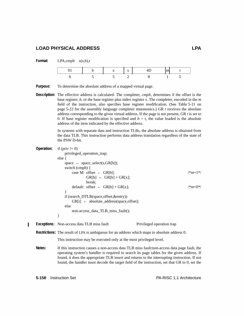
5-158 Instruction Set PA-RISC 1.1 Architecture
LOAD PHYSICAL ADDRESS LPA
Format: LPA,cmplt x(s,b),t
Purpose: To determine the absolute address of a mapped virtual page.
Description: The effective address is calculated. The completer,cmplt, determines if the offset is thebase register,b, or the base register plus index registerx. The completer, encoded in themfield of the instruction, also specifies base register modification. (See Table 5-11 onpage 5-22 for the assembly language completer mnemonics.) GRt receives the absoluteaddress corresponding to the given virtual address. If the page is not present, GRt is set to0. If base register modification is specified andb = t, the value loaded is the absoluteaddress of the item indicated by the effective address.
In systems with separate data and instruction TLBs, the absolute address is obtained fromthe data TLB. This instruction performs data address translation regardless of the state ofthe PSW D-bit.
Operation: if (priv != 0)privileged_operation_trap;
else {space← space_select(s,GR[b]);switch (cmplt) {
case M: offset← GR[b]; /*m=1*/GR[b] ← GR[b] + GR[x];break;
default: offset← GR[b] + GR[x]; /*m=0*/}if (search_DTLB(space,offset,&entry))
GR[t] ← absolute_address(space,offset);else
non-access_data_TLB_miss_fault();}
Exceptions: Non-access data TLB miss fault Privileged operation trap
Restrictions: The result ofLPA is ambiguous for an address which maps to absolute address 0.
This instruction may be executed only at the most privileged level.
Notes: If this instruction causes a non-access data TLB miss fault/non-access data page fault, theoperating system’s handler is required to search its page tables for the given address. Iffound, it does the appropriate TLB insert and returns to the interrupting instruction. If notfound, the handler must decode the target field of the instruction, set that GR to 0, set the
01 b x s 4D m t
6 5 5 2 8 1 5
5-159PA-RISC 1.1 Architecture Instruction Set
IPSW[N] bit to 1, and return to the interrupting instruction.
Level 0: This instruction is an undefined operation.
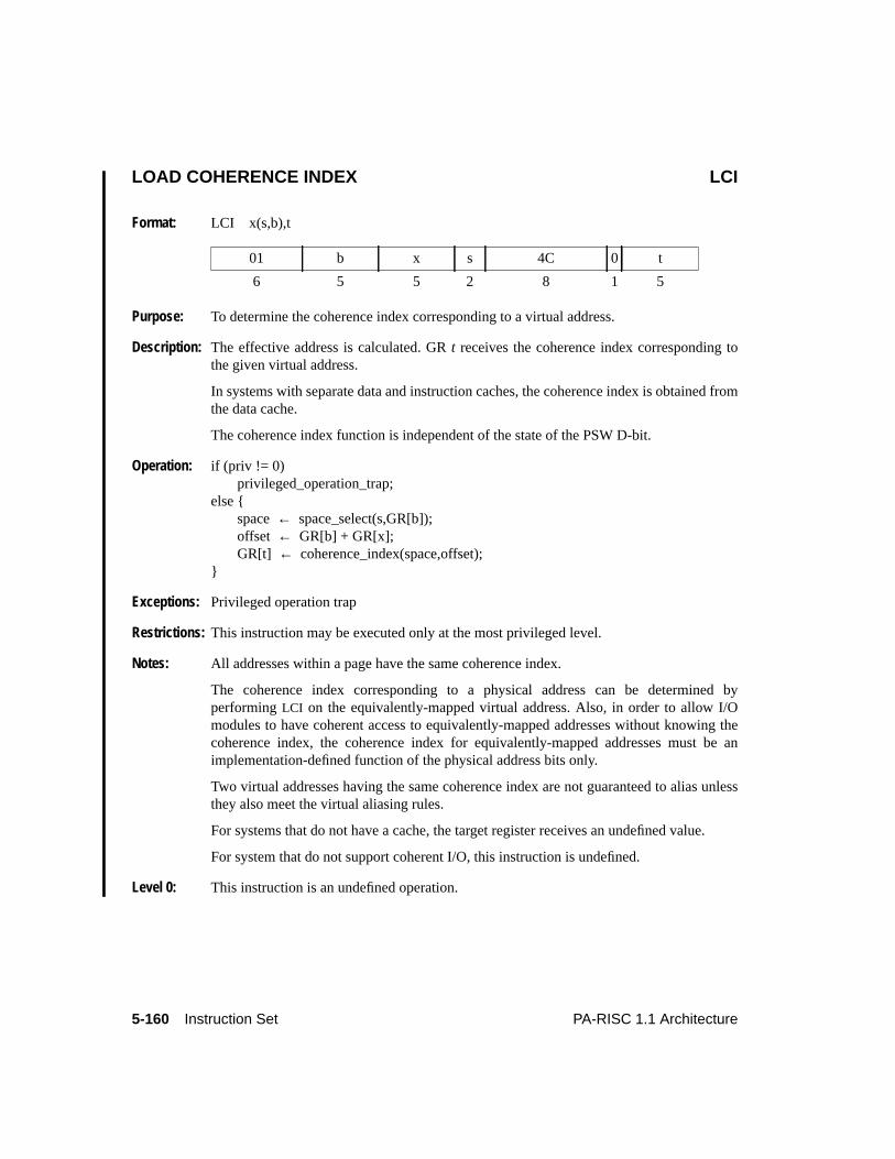
5-160 Instruction Set PA-RISC 1.1 Architecture
LOAD COHERENCE INDEX LCI
Format: LCI x(s,b),t
Purpose: To determine the coherence index corresponding to a virtual address.
Description: The effective address is calculated. GRt receives the coherence index corresponding tothe given virtual address.
In systems with separate data and instruction caches, the coherence index is obtained fromthe data cache.
The coherence index function is independent of the state of the PSW D-bit.
Operation: if (priv != 0)privileged_operation_trap;
else {space← space_select(s,GR[b]);offset ← GR[b] + GR[x];GR[t] ← coherence_index(space,offset);
}
Exceptions: Privileged operation trap
Restrictions: This instruction may be executed only at the most privileged level.
Notes: All addresses within a page have the same coherence index.
The coherence index corresponding to a physical address can be determined byperformingLCI on the equivalently-mapped virtual address. Also, in order to allow I/Omodules to have coherent access to equivalently-mapped addresses without knowing thecoherence index, the coherence index for equivalently-mapped addresses must be animplementation-defined function of the physical address bits only.
Two virtual addresses having the same coherence index are not guaranteed to alias unlessthey also meet the virtual aliasing rules.
For systems that do not have a cache, the target register receives an undefined value.
For system that do not support coherent I/O, this instruction is undefined.
Level 0: This instruction is an undefined operation.
01 b x s 4C 0 t
6 5 5 2 8 1 5
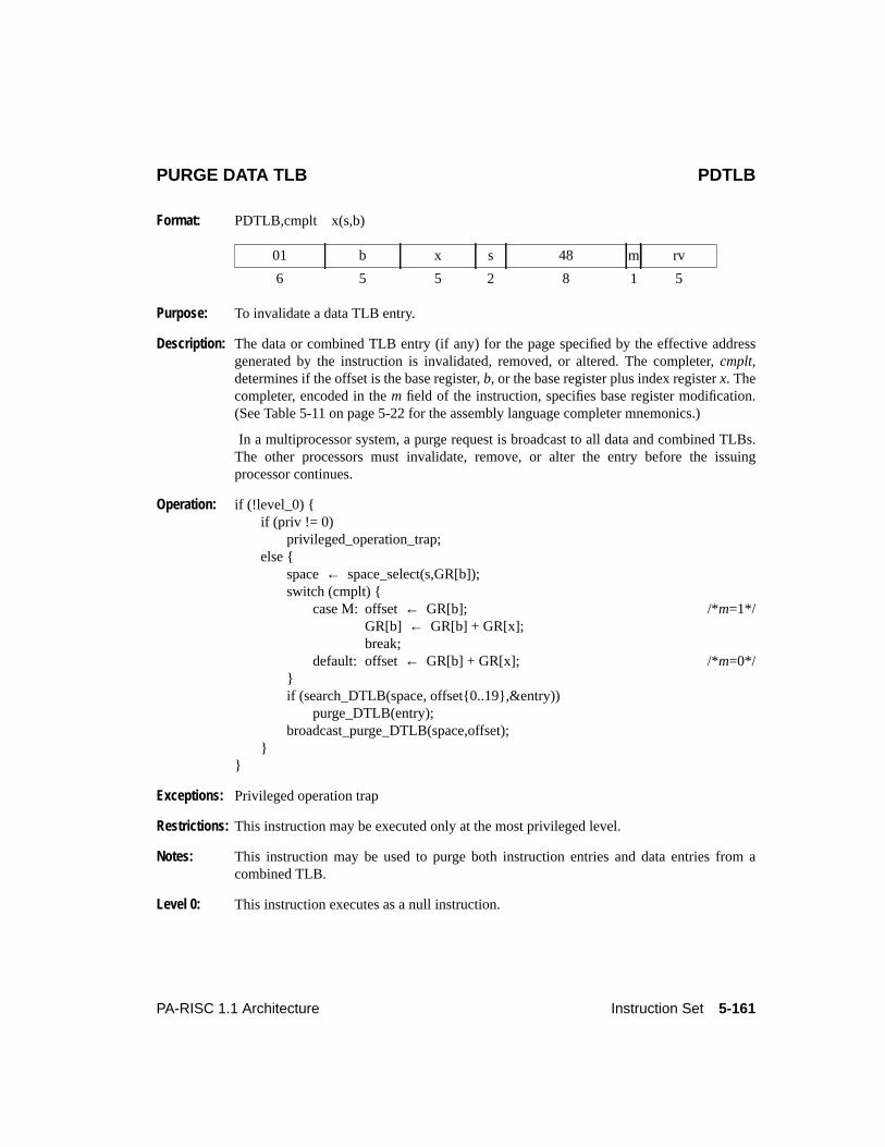
5-161PA-RISC 1.1 Architecture Instruction Set
PURGE DATA TLB PDTLB
Format: PDTLB,cmplt x(s,b)
Purpose: To invalidate a data TLB entry.
Description: The data or combined TLB entry (if any) for the page specified by the effective addressgenerated by the instruction is invalidated, removed, or altered. The completer,cmplt,determines if the offset is the base register,b, or the base register plus index registerx. Thecompleter, encoded in them field of the instruction, specifies base register modification.(See Table 5-11 on page 5-22 for the assembly language completer mnemonics.)
In a multiprocessor system, a purge request is broadcast to all data and combined TLBs.The other processors must invalidate, remove, or alter the entry before the issuingprocessor continues.
Operation: if (!level_0) {if (priv != 0)
privileged_operation_trap;else {
space← space_select(s,GR[b]);switch (cmplt) {
case M: offset← GR[b]; /*m=1*/GR[b] ← GR[b] + GR[x];break;
default: offset← GR[b] + GR[x]; /*m=0*/}if (search_DTLB(space, offset{0..19},&entry))
purge_DTLB(entry);broadcast_purge_DTLB(space,offset);
}}
Exceptions: Privileged operation trap
Restrictions: This instruction may be executed only at the most privileged level.
Notes: This instruction may be used to purge both instruction entries and data entries from acombined TLB.
Level 0: This instruction executes as a null instruction.
01 b x s 48 m rv
6 5 5 2 8 1 5
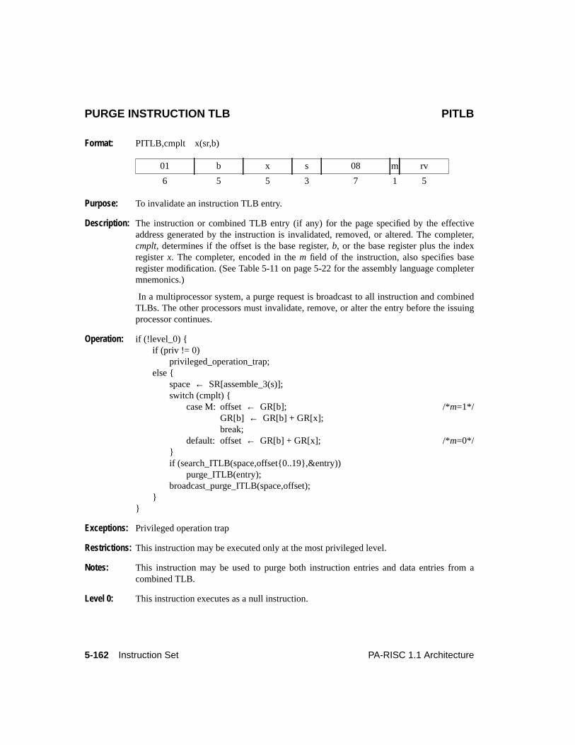
5-162 Instruction Set PA-RISC 1.1 Architecture
PURGE INSTRUCTION TLB PITLB
Format: PITLB,cmplt x(sr,b)
Purpose: To invalidate an instruction TLB entry.
Description: The instruction or combined TLB entry (if any) for the page specified by the effectiveaddress generated by the instruction is invalidated, removed, or altered. The completer,cmplt, determines if the offset is the base register,b, or the base register plus the indexregisterx. The completer, encoded in them field of the instruction, also specifies baseregister modification. (See Table 5-11 on page 5-22 for the assembly language completermnemonics.)
In a multiprocessor system, a purge request is broadcast to all instruction and combinedTLBs. The other processors must invalidate, remove, or alter the entry before the issuingprocessor continues.
Operation: if (!level_0) {if (priv != 0)
privileged_operation_trap;else {
space← SR[assemble_3(s)];switch (cmplt) {
case M: offset← GR[b]; /*m=1*/GR[b] ← GR[b] + GR[x];break;
default: offset← GR[b] + GR[x]; /*m=0*/}if (search_ITLB(space,offset{0..19},&entry))
purge_ITLB(entry);broadcast_purge_ITLB(space,offset);
}}
Exceptions: Privileged operation trap
Restrictions: This instruction may be executed only at the most privileged level.
Notes: This instruction may be used to purge both instruction entries and data entries from acombined TLB.
Level 0: This instruction executes as a null instruction.
01 b x s 08 m rv
6 5 5 3 7 1 5
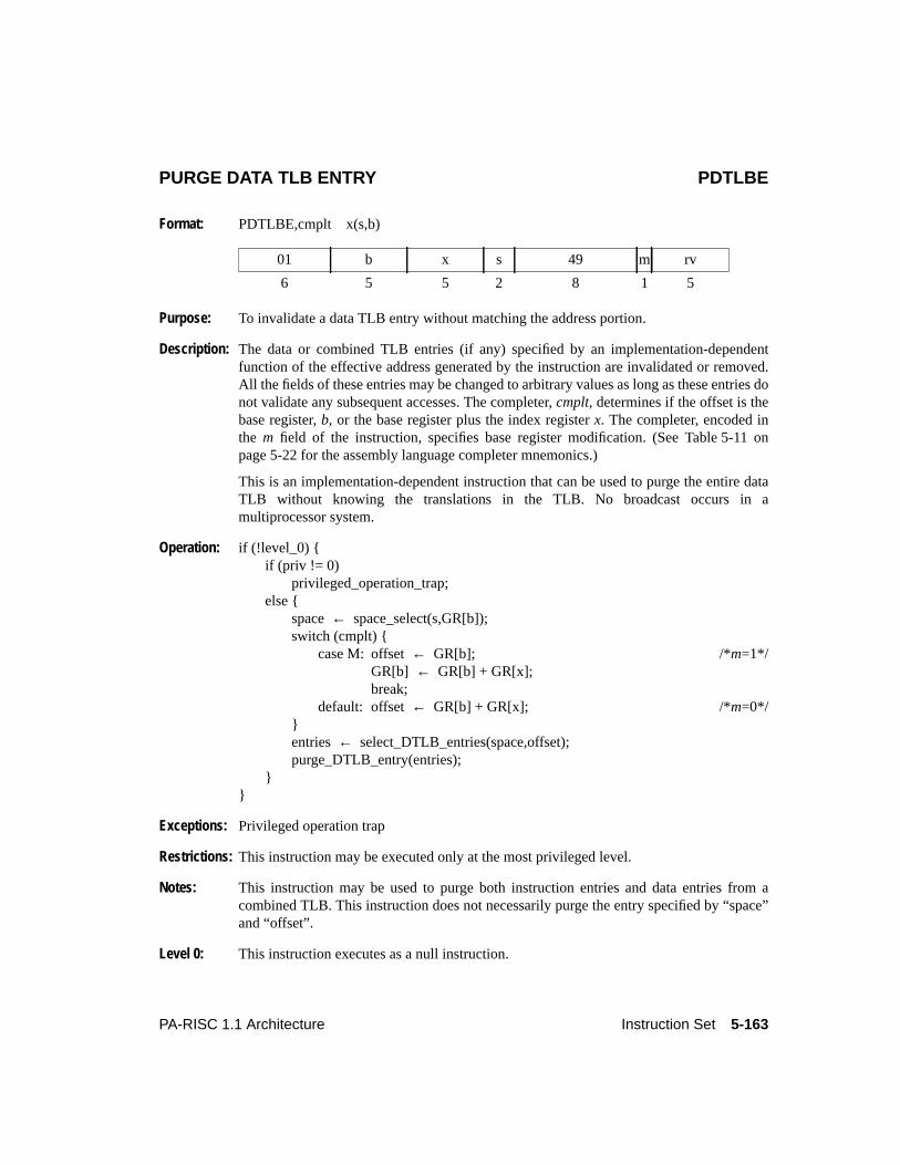
5-163PA-RISC 1.1 Architecture Instruction Set
PURGE DATA TLB ENTRY PDTLBE
Format: PDTLBE,cmplt x(s,b)
Purpose: To invalidate a data TLB entry without matching the address portion.
Description: The data or combined TLB entries (if any) specified by an implementation-dependentfunction of the effective address generated by the instruction are invalidated or removed.All the fields of these entries may be changed to arbitrary values as long as these entries donot validate any subsequent accesses. The completer,cmplt, determines if the offset is thebase register,b, or the base register plus the index registerx. The completer, encoded inthe m field of the instruction, specifies base register modification. (See Table 5-11 onpage 5-22 for the assembly language completer mnemonics.)
This is an implementation-dependent instruction that can be used to purge the entire dataTLB without knowing the translations in the TLB. No broadcast occurs in amultiprocessor system.
Operation: if (!level_0) {if (priv != 0)
privileged_operation_trap;else {
space← space_select(s,GR[b]);switch (cmplt) {
case M: offset← GR[b]; /*m=1*/GR[b] ← GR[b] + GR[x];break;
default: offset← GR[b] + GR[x]; /*m=0*/}entries ← select_DTLB_entries(space,offset);purge_DTLB_entry(entries);
}}
Exceptions: Privileged operation trap
Restrictions: This instruction may be executed only at the most privileged level.
Notes: This instruction may be used to purge both instruction entries and data entries from acombined TLB. This instruction does not necessarily purge the entry specified by “space”and “offset”.
Level 0: This instruction executes as a null instruction.
01 b x s 49 m rv
6 5 5 2 8 1 5
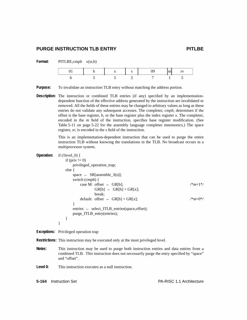
5-164 Instruction Set PA-RISC 1.1 Architecture
PURGE INSTRUCTION TLB ENTRY PITLBE
Format: PITLBE,cmplt x(sr,b)
Purpose: To invalidate an instruction TLB entry without matching the address portion.
Description: The instruction or combined TLB entries (if any) specified by an implementation-dependent function of the effective address generated by the instruction are invalidated orremoved. All the fields of these entries may be changed to arbitrary values as long as theseentries do not validate any subsequent accesses. The completer,cmplt, determines if theoffset is the base register,b, or the base register plus the index registerx. The completer,encoded in them field of the instruction, specifies base register modification. (SeeTable 5-11 on page 5-22 for the assembly language completer mnemonics.) The spaceregister,sr, is encoded in thes field of the instruction.
This is an implementation-dependent instruction that can be used to purge the entireinstruction TLB without knowing the translations in the TLB. No broadcast occurs in amultiprocessor system.
Operation: if (!level_0) {if (priv != 0)
privileged_operation_trap;else {
space← SR[assemble_3(s)];switch (cmplt) {
case M: offset← GR[b]; /*m=1*/GR[b] ← GR[b] + GR[x];break;
default: offset← GR[b] + GR[x]; /*m=0*/}entries ← select_ITLB_entries(space,offset);purge_ITLB_entry(entries);
}}
Exceptions: Privileged operation trap
Restrictions: This instruction may be executed only at the most privileged level.
Notes: This instruction may be used to purge both instruction entries and data entries from acombined TLB. This instruction does not necessarily purge the entry specified by “space”and “offset”.
Level 0: This instruction executes as a null instruction.
01 b x s 09 m rv
6 5 5 3 7 1 5
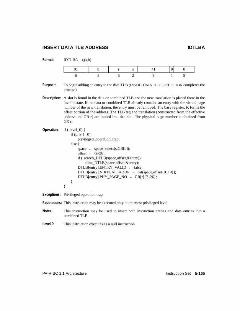
5-165PA-RISC 1.1 Architecture Instruction Set
INSERT DATA TLB ADDRESS IDTLBA
Format: IDTLBA r,(s,b)
Purpose: To begin adding an entry to the data TLB (INSERT DATA TLB PROTECTION completes theprocess).
Description: A slot is found in the data or combined TLB and the new translation is placed there in theinvalid state. If the data or combined TLB already contains an entry with the virtual pagenumber of the new translation, the entry must be removed. The base register,b, forms theoffset portion of the address. The TLB tag and translation (constructed from the effectiveaddress and GRr) are loaded into that slot. The physical page number is obtained fromGR r.
Operation: if (!level_0) {if (priv != 0)
privileged_operation_trap;else {
space← space_select(s,GR[b]);offset ← GR[b];if (!search_DTLB(space,offset,&entry))
alloc_DTLB(space,offset,&entry);DTLB[entry].ENTRY_VALID ← false;DTLB[entry].VIRTUAL_ADDR ← cat(space,offset{0..19});DTLB[entry].PHY_PAGE_NO← GR[r]{7..26};
}}
Exceptions: Privileged operation trap
Restrictions: This instruction may be executed only at the most privileged level.
Notes: This instruction may be used to insert both instruction entries and data entries into acombined TLB.
Level 0: This instruction executes as a null instruction.
01 b r s 41 0 0
6 5 5 2 8 1 5
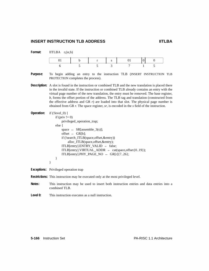
5-166 Instruction Set PA-RISC 1.1 Architecture
INSERT INSTRUCTION TLB ADDRESS IITLBA
Format: IITLBA r,(sr,b)
Purpose: To begin adding an entry to the instruction TLB (INSERT INSTRUCTION TLBPROTECTION completes the process).
Description: A slot is found in the instruction or combined TLB and the new translation is placed therein the invalid state. If the instruction or combined TLB already contains an entry with thevirtual page number of the new translation, the entry must be removed. The base register,b, forms the offset portion of the address. The TLB tag and translation (constructed fromthe effective address and GRr) are loaded into that slot. The physical page number isobtained from GRr. The space register,sr, is encoded in thes field of the instruction.
Operation: if (!level_0) {if (priv != 0)
privileged_operation_trap;else {
space← SR[assemble_3(s)];offset ← GR[b];if (!search_ITLB(space,offset,&entry))
alloc_ITLB(space,offset,&entry);ITLB[entry].ENTRY_VALID ← false;ITLB[entry].VIRTUAL_ADDR ← cat(space,offset{0..19});ITLB[entry].PHY_PAGE_NO ← GR[r]{7..26};
}}
Exceptions: Privileged operation trap
Restrictions: This instruction may be executed only at the most privileged level.
Notes: This instruction may be used to insert both instruction entries and data entries into acombined TLB.
Level 0: This instruction executes as a null instruction.
01 b r s 01 0 0
6 5 5 3 7 1 5
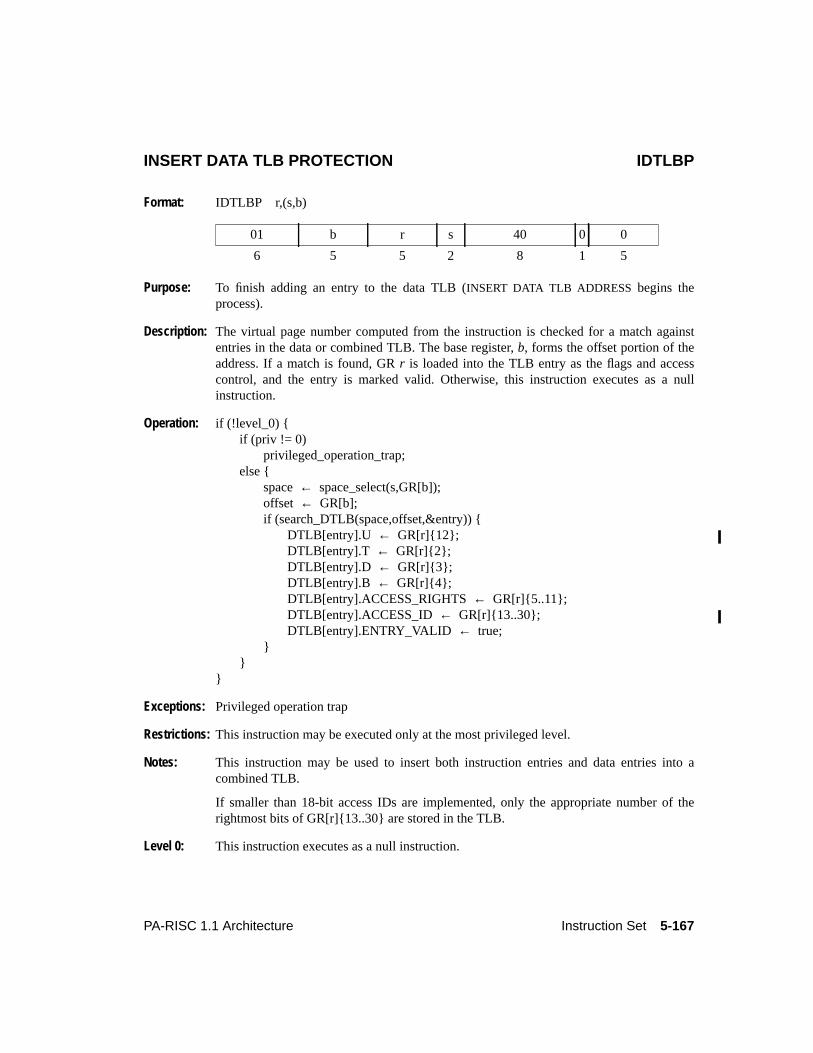
5-167PA-RISC 1.1 Architecture Instruction Set
INSERT DATA TLB PROTECTION IDTLBP
Format: IDTLBP r,(s,b)
Purpose: To finish adding an entry to the data TLB (INSERT DATA TLB ADDRESS begins theprocess).
Description: The virtual page number computed from the instruction is checked for a match againstentries in the data or combined TLB. The base register,b, forms the offset portion of theaddress. If a match is found, GRr is loaded into the TLB entry as the flags and accesscontrol, and the entry is marked valid. Otherwise, this instruction executes as a nullinstruction.
Operation: if (!level_0) {if (priv != 0)
privileged_operation_trap;else {
space← space_select(s,GR[b]);offset ← GR[b];if (search_DTLB(space,offset,&entry)) {
DTLB[entry].U ← GR[r]{12};DTLB[entry].T ← GR[r]{2};DTLB[entry].D ← GR[r]{3};DTLB[entry].B ← GR[r]{4};DTLB[entry].ACCESS_RIGHTS← GR[r]{5..11};DTLB[entry].ACCESS_ID ← GR[r]{13..30};DTLB[entry].ENTRY_VALID ← true;
}}
}
Exceptions: Privileged operation trap
Restrictions: This instruction may be executed only at the most privileged level.
Notes: This instruction may be used to insert both instruction entries and data entries into acombined TLB.
If smaller than 18-bit access IDs are implemented, only the appropriate number of therightmost bits of GR[r]{13..30} are stored in the TLB.
Level 0: This instruction executes as a null instruction.
01 b r s 40 0 0
6 5 5 2 8 1 5
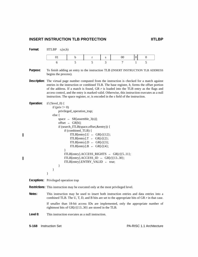
5-168 Instruction Set PA-RISC 1.1 Architecture
INSERT INSTRUCTION TLB PROTECTION IITLBP
Format: IITLBP r,(sr,b)
Purpose: To finish adding an entry to the instruction TLB (INSERT INSTRUCTION TLB ADDRESSbegins the process).
Description: The virtual page number computed from the instruction is checked for a match againstentries in the instruction or combined TLB. The base register,b, forms the offset portionof the address. If a match is found, GRr is loaded into the TLB entry as the flags andaccess control, and the entry is marked valid. Otherwise, this instruction executes as a nullinstruction. The space register,sr, is encoded in thes field of the instruction.
Operation: if (!level_0) {if (priv != 0)
privileged_operation_trap;else {
space← SR[assemble_3(s)];offset ← GR[b];if (search_ITLB(space,offset,&entry)) {
if (combined_TLB) {ITLB[entry].U ← GR[r]{12};ITLB[entry].T ← GR[r]{2};ITLB[entry].D ← GR[r]{3};ITLB[entry].B ← GR[r]{4};
}ITLB[entry].ACCESS_RIGHTS← GR[r]{5..11};ITLB[entry].ACCESS_ID ← GR[r]{13..30};ITLB[entry].ENTRY_VALID ← true;
}}
}
Exceptions: Privileged operation trap
Restrictions: This instruction may be executed only at the most privileged level.
Notes: This instruction may be used to insert both instruction entries and data entries into acombined TLB. The U, T, D, and B bits are set to the appropriate bits of GRr in that case.
If smaller than 18-bit access IDs are implemented, only the appropriate number ofrightmost bits of GR[r]{13..30} are stored in the TLB.
Level 0: This instruction executes as a null instruction.
01 b r s 00 0 0
6 5 5 3 7 1 5
5-169PA-RISC 1.1 Architecture Instruction Set
PURGE DATA CACHE PDC
Format: PDC,cmplt x(s,b)
Purpose: To invalidate a data cache line.
Description: The cache line (if present) specified by the effective address generated by the instruction isinvalidated from the data cache. If the privilege level is non-zero and the cache line isdirty then it is written back to memory before being invalidated. If the privilege level iszero and the line is dirty then the implementation may optionally write back the line tomemory.
The completer,cmplt, determines if the offset is the base register,b, or the base registerplus the index registerx. The completer, encoded in them field of the instruction, specifiesbase register modification. (See Table 5-11 on page 5-22 for the assembly languagecompleter mnemonics.)
If a cache purge operation is performed, write access to the data is required. The PSW D-bit (Data address translation enable) determines whether a virtual or absolute address isused.
In a multiprocessor system, a purge or flush request is broadcast to all data and combinedcaches.
Operation: space← space_select(s,GR[b]);switch (cmplt) {
case M: offset← GR[b]; /*m=1*/GR[b] ← GR[b] + GR[x];break;
default: offset← GR[b] + GR[x]; /*m=0*/}if (priv != 0)
flush_data_cache(space,offset);else
purge_or_flush_data_cache(space,offset);
Exceptions: Non-access data TLB miss fault Data memory break trapData memory access rights trap Data debug trapData memory protection ID trap
Notes: For systems that do not have a cache, this instruction executes as a null instruction.
At privilege level zero, implementations are encouraged to purge the cache line forperformance reasons.
This instruction may be executed out of sequence but must satisfy the instruction ordering
01 b x s 4E m 0
6 5 5 2 8 1 5

5-170 Instruction Set PA-RISC 1.1 Architecture
constraints. TheSYNC instruction enforces program order with respect to the instructionsfollowing theSYNC.
A data debug trap is not taken if aPDC causes a cache flush operation; the trap is takenonly if a cache purge operation is performed to an address matching a data breakpoint withits w (write access) bit enabled..
5-171PA-RISC 1.1 Architecture Instruction Set
FLUSH DATA CACHE FDC
Format: FDC,cmplt x(s,b)
Purpose: To invalidate a data cache line and write it back to memory if it is dirty.
Description: The data cache line (if present) specified by the effective address generated by theinstruction is written back to memory, if and only if it is dirty, and then invalidated fromthe data cache. The completer,cmplt, determines if the offset is the base register,b, or thebase register plus the index registerx. The completer, encoded in them-field of theinstruction, specifies base register modification. (See Table 5-11 on page 5-22 for theassembly language completer mnemonics.) The PSW D-bit (Data address translationenable) determines whether a virtual or absolute address is used.
A cache line is calleddirty if any byte has been written to since it was read from memoryor if a STBYS,E to the leftmost byte of a word has been performed.
In a multiprocessor system, a flush request is broadcast to all data and combined caches.
Operation: space← space_select(s,GR[b]);switch (cmplt) {
case M: offset← GR[b]; /*m=1*/GR[b] ← GR[b] + GR[x];break;
default: offset← GR[b] + GR[x]; /*m=0*/}flush_data_cache(space,offset);
Exceptions: Non-access data TLB miss fault
Notes: For systems that do not have a cache, this instruction executes as a null instruction.
In systems with a combined cache, this instruction may be used to flush both data andinstruction lines from the cache.
This instruction may be executed out of sequence but must satisfy the instruction orderingconstraints. TheSYNC instruction enforces program order with respect to the instructionsfollowing theSYNC.
01 b x s 4A m rv
6 5 5 2 8 1 5
5-172 Instruction Set PA-RISC 1.1 Architecture
FLUSH INSTRUCTION CACHE FIC
Format: FIC,cmplt x(sr,b)
Purpose: To invalidate an instruction cache line.
Description: The instruction cache line (if any) specified by the effective address generated by theinstruction is invalidated in the instruction cache. The completer,cmplt, determines if theoffset is the base register,b, or the base register plus the index registerx. The completer,encoded in them-field of the instruction, specifies base register modification. (SeeTable 5-11 on page 5-22 for the assembly language completer mnemonics.) The spaceregister,sr, is encoded in thes field of the instruction. The PSW D-bit (Data addresstranslation enable) determines whether a virtual or absolute address is used.
Either the instruction TLB or the data TLB can be used to perform the address translationfor the address to be flushed. If the data TLB is used, a TLB miss fault is reported using anon-access data TLB miss fault.
In a multiprocessor system, a flush request is broadcast to all instruction and combinedcaches.
Operation: space← SR[assemble_3(s)];switch (cmplt) {
case M: offset← GR[b]; /*m=1*/GR[b] ← GR[b] + GR[x];break;
default: offset← GR[b] + GR[x]; /*m=0*/}flush_instruction_cache(space,offset);
Exceptions: Non-access instruction TLB miss faultNon-access data TLB miss fault
Notes: For systems that do not have a cache, this instruction executes as a null instruction.
In systems with a combined cache, this instruction may be used to flush both instructionand data lines from the cache, including writing them back to main memory, if they aredirty.
This instruction may be executed out of sequence but must satisfy the instruction orderingconstraints. TheSYNC instruction enforces program order with respect to the instructionsfollowing theSYNC.
01 b x s 0A m rv
6 5 5 3 7 1 5
5-173PA-RISC 1.1 Architecture Instruction Set
FLUSH DATA CACHE ENTRY FDCE
Format: FDCE,cmplt x(s,b)
Purpose: To provide for flushing the entire data or combined cache by causing zero or more cachelines to be invalidated.
Description: Zero or more cache lines specified by an implementation-dependent function of theeffective address are written back to main memory, if and only if they are dirty, and areinvalidated in the data or combined cache. The completer,cmplt, determines if the offset isthe base register,b, or the base register plus the index registerx. The completer, encodedin the m-field of the instruction, specifies base register modification. No addresstranslation is performed. (See Table 5-11 on page 5-22 for the assembly languagecompleter mnemonics.)
When this instruction is used in an architecturally defined cache flush loop, the entire dataor combined cache will be flushed upon completion of the loop.
Operation: space← space_select(s,GR[b]);switch (cmplt) {
case M: offset← GR[b]; /*m=1*/GR[b] ← GR[b] + GR[x];break;
default: offset← GR[b] + GR[x]; /*m=0*/}entries ← select_data_cache_entries(space,offset);flush_data_cache_entry(entries);
Exceptions: None
Notes: In a multiprocessor system, this instruction is not broadcast to other processors. Thisinstruction does not necessarily flush the entry specified by “space” and “offset”.
For systems that do not have a cache, this instruction executes as a null instruction.
01 b x s 4B m rv
6 5 5 2 8 1 5
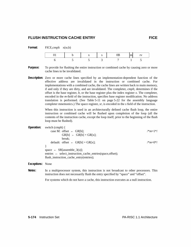
5-174 Instruction Set PA-RISC 1.1 Architecture
FLUSH INSTRUCTION CACHE ENTRY FICE
Format: FICE,cmplt x(sr,b)
Purpose: To provide for flushing the entire instruction or combined cache by causing zero or morecache lines to be invalidated.
Description: Zero or more cache lines specified by an implementation-dependent function of theeffective address are invalidated in the instruction or combined cache. Forimplementations with a combined cache, the cache lines are written back to main memory,if and only if they are dirty, and are invalidated. The completer,cmplt, determines if theoffset is the base register,b, or the base register plus the index registerx. The completer,encoded in them-field of the instruction, specifies base register modification. No addresstranslation is performed. (See Table 5-11 on page 5-22 for the assembly languagecompleter mnemonics.) The space register,sr, is encoded in thes field of the instruction.
When this instruction is used in an architecturally defined cache flush loop, the entireinstruction or combined cache will be flushed upon completion of the loop (all thecontents of the instruction cache, except the loop itself, prior to the beginning of the flushloop must be flushed).
Operation: switch (cmplt) {case M: offset← GR[b]; /*m=1*/
GR[b] ← GR[b] + GR[x];break;
default: offset← GR[b] + GR[x]; /*m=0*/}space← SR[assemble_3(s)];entries ← select_instruction_cache_entries(space,offset);flush_instruction_cache_entry(entries);
Exceptions: None
Notes: In a multiprocessor system, this instruction is not broadcast to other processors. Thisinstruction does not necessarily flush the entry specified by “space” and “offset”.
For systems which do not have a cache, this instruction executes as a null instruction.
01 b x s 0B m rv
6 5 5 3 7 1 5
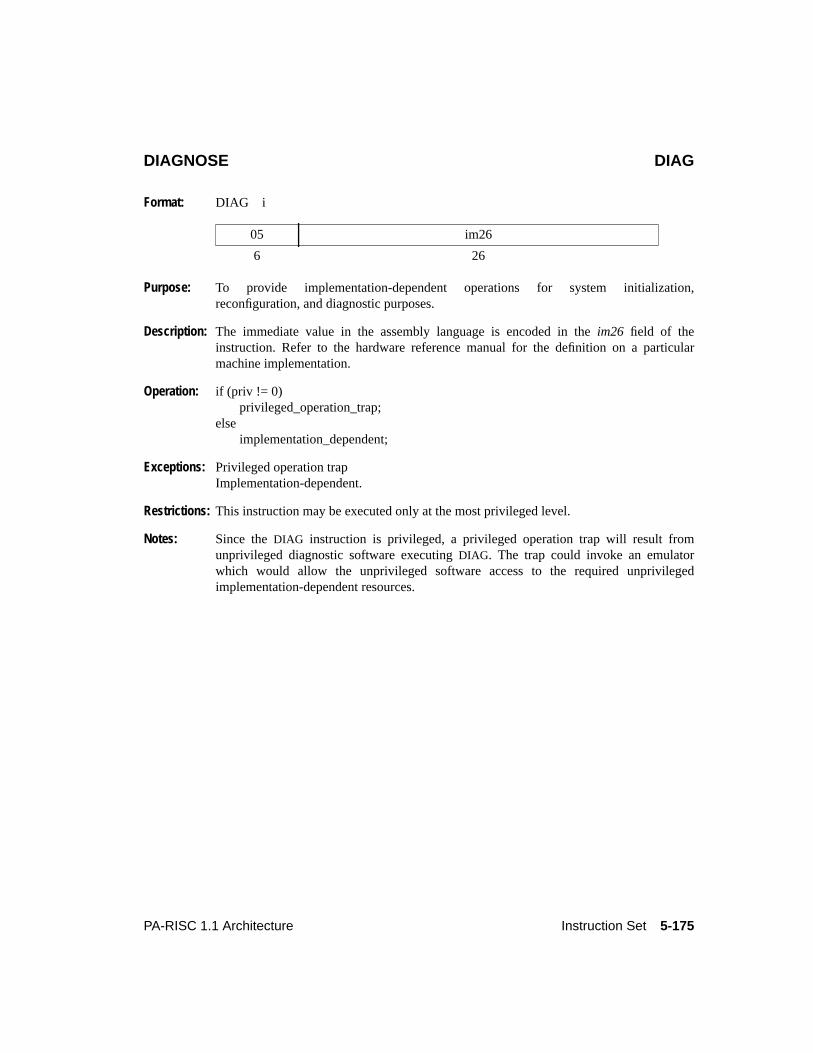
5-175PA-RISC 1.1 Architecture Instruction Set
DIAGNOSE DIAG
Format: DIAG i
Purpose: To provide implementation-dependent operations for system initialization,reconfiguration, and diagnostic purposes.
Description: The immediate value in the assembly language is encoded in theim26 field of theinstruction. Refer to the hardware reference manual for the definition on a particularmachine implementation.
Operation: if (priv != 0)privileged_operation_trap;
elseimplementation_dependent;
Exceptions: Privileged operation trapImplementation-dependent.
Restrictions: This instruction may be executed only at the most privileged level.
Notes: Since theDIAG instruction is privileged, a privileged operation trap will result fromunprivileged diagnostic software executingDIAG. The trap could invoke an emulatorwhich would allow the unprivileged software access to the required unprivilegedimplementation-dependent resources.
05 im26
6 26
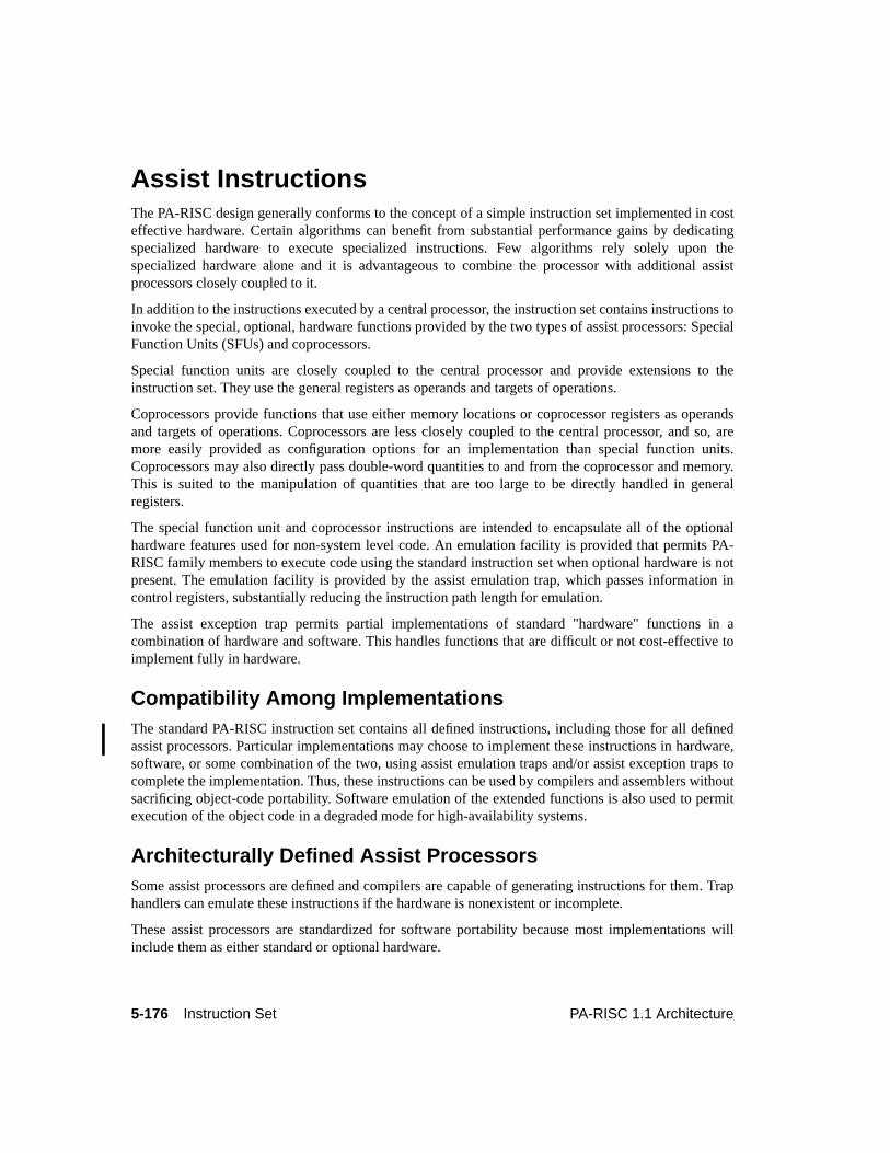
5-176 Instruction Set PA-RISC 1.1 Architecture
5Instruction Set
Assist InstructionsThe PA-RISC design generally conforms to the concept of a simple instruction set implemented in costeffective hardware. Certain algorithms can benefit from substantial performance gains by dedicatingspecialized hardware to execute specialized instructions. Few algorithms rely solely upon thespecialized hardware alone and it is advantageous to combine the processor with additional assistprocessors closely coupled to it.
In addition to the instructions executed by a central processor, the instruction set contains instructions toinvoke the special, optional, hardware functions provided by the two types of assist processors: SpecialFunction Units (SFUs) and coprocessors.
Special function units are closely coupled to the central processor and provide extensions to theinstruction set. They use the general registers as operands and targets of operations.
Coprocessors provide functions that use either memory locations or coprocessor registers as operandsand targets of operations. Coprocessors are less closely coupled to the central processor, and so, aremore easily provided as configuration options for an implementation than special function units.Coprocessors may also directly pass double-word quantities to and from the coprocessor and memory.This is suited to the manipulation of quantities that are too large to be directly handled in generalregisters.
The special function unit and coprocessor instructions are intended to encapsulate all of the optionalhardware features used for non-system level code. An emulation facility is provided that permits PA-RISC family members to execute code using the standard instruction set when optional hardware is notpresent. The emulation facility is provided by the assist emulation trap, which passes information incontrol registers, substantially reducing the instruction path length for emulation.
The assist exception trap permits partial implementations of standard "hardware" functions in acombination of hardware and software. This handles functions that are difficult or not cost-effective toimplement fully in hardware.
Compatibility Among ImplementationsThe standard PA-RISC instruction set contains all defined instructions, including those for all definedassist processors. Particular implementations may choose to implement these instructions in hardware,software, or some combination of the two, using assist emulation traps and/or assist exception traps tocomplete the implementation. Thus, these instructions can be used by compilers and assemblers withoutsacrificing object-code portability. Software emulation of the extended functions is also used to permitexecution of the object code in a degraded mode for high-availability systems.
Architecturally Defined Assist ProcessorsSome assist processors are defined and compilers are capable of generating instructions for them. Traphandlers can emulate these instructions if the hardware is nonexistent or incomplete.
These assist processors are standardized for software portability because most implementations willinclude them as either standard or optional hardware.
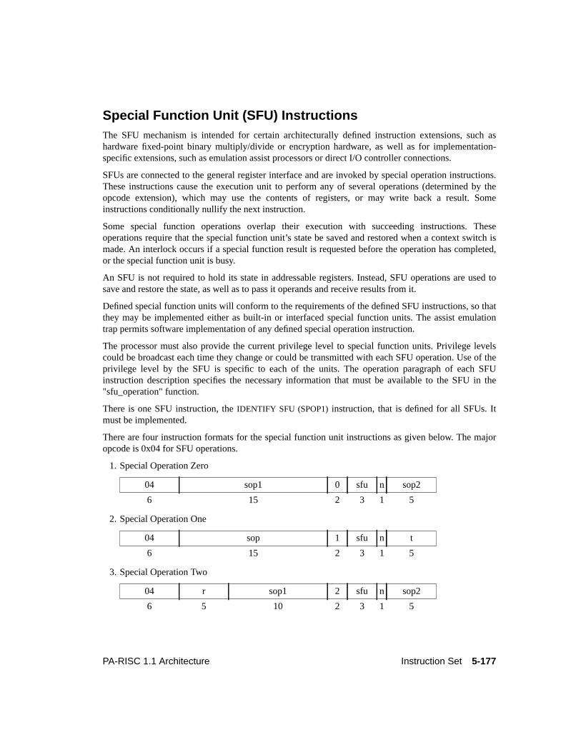
5-177PA-RISC 1.1 Architecture Instruction Set
Special Function Unit (SFU) InstructionsThe SFU mechanism is intended for certain architecturally defined instruction extensions, such ashardware fixed-point binary multiply/divide or encryption hardware, as well as for implementation-specific extensions, such as emulation assist processors or direct I/O controller connections.
SFUs are connected to the general register interface and are invoked by special operation instructions.These instructions cause the execution unit to perform any of several operations (determined by theopcode extension), which may use the contents of registers, or may write back a result. Someinstructions conditionally nullify the next instruction.
Some special function operations overlap their execution with succeeding instructions. Theseoperations require that the special function unit’s state be saved and restored when a context switch ismade. An interlock occurs if a special function result is requested before the operation has completed,or the special function unit is busy.
An SFU is not required to hold its state in addressable registers. Instead, SFU operations are used tosave and restore the state, as well as to pass it operands and receive results from it.
Defined special function units will conform to the requirements of the defined SFU instructions, so thatthey may be implemented either as built-in or interfaced special function units. The assist emulationtrap permits software implementation of any defined special operation instruction.
The processor must also provide the current privilege level to special function units. Privilege levelscould be broadcast each time they change or could be transmitted with each SFU operation. Use of theprivilege level by the SFU is specific to each of the units. The operation paragraph of each SFUinstruction description specifies the necessary information that must be available to the SFU in the"sfu_operation" function.
There is one SFU instruction, theIDENTIFY SFU (SPOP1) instruction, that is defined for all SFUs. Itmust be implemented.
There are four instruction formats for the special function unit instructions as given below. The majoropcode is 0x04 for SFU operations.
1. Special Operation Zero
2. Special Operation One
3. Special Operation Two
04 sop1 0 sfu n sop2
6 15 2 3 1 5
04 sop 1 sfu n t
6 15 2 3 1 5
04 r sop1 2 sfu n sop2
6 5 10 2 3 1 5
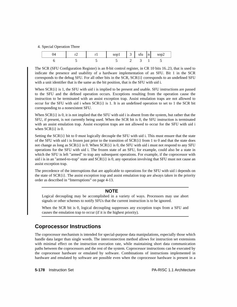
5-178 Instruction Set PA-RISC 1.1 Architecture
4. Special Operation Three
The SCR (SFU Configuration Register) is an 8-bit control register, in CR 10 bits 16..23, that is used toindicate the presence and usability of a hardware implementation of an SFU. Bit 1 in the SCRcorresponds to the debug SFU. For all other bits in the SCR, SCR{i} corresponds to an undefined SFUwith a unit identifier that is the same as the bit position, that is the SFU with uid i.
When SCR{i} is 1, the SFU with uid i is implied to be present and usable. SFU instructions are passedto the SFU and the defined operation occurs. Exceptions resulting from the operation cause theinstruction to be terminated with an assist exception trap. Assist emulation traps are not allowed tooccur for the SFU with uid i when SCR{i} is 1. It is an undefined operation to set to 1 the SCR bitcorresponding to a nonexistent SFU.
When SCR{i} is 0, it is not implied that the SFU with uid i is absent from the system, but rather that theSFU, if present, is not currently being used. When the SCR bit is 0, the SFU instruction is terminatedwith an assist emulation trap. Assist exception traps are not allowed to occur for the SFU with uid iwhen SCR{i} is 0.
Setting the SCR{i} bit to 0 must logically decouple the SFU with uid i. This must ensure that the stateof the SFU with uid i is frozen just prior to the transition of SCR{i} from 1 to 0 and that the state doesnot change as long as SCR{i} is 0. When SCR{i} is 0, the SFU with uid i must not respond to any SFUoperations for the SFU with uid i. The frozen state of an SFU, for example, could also be a state inwhich the SFU is left "armed" to trap any subsequent operations. For example, if the coprocessor withuid i is in an "armed-to-trap" state and SCR{i} is 0, any operation involving that SFU must not cause anassist exception trap.
The precedence of the interruptions that are applicable to operations for the SFU with uid i depends onthe state of SCR{i}. The assist exception trap and assist emulation trap are always taken in the priorityorder as described in “Interruptions” on page 4-13.
NOTELogical decoupling may be accomplished in a variety of ways. Processors may use abortsignals or other schemes to notify SFUs that the current instruction is to be ignored.
When the SCR bit is 0, logical decoupling suppresses any exception traps from a SFU andcauses the emulation trap to occur (if it is the highest priority).
Coprocessor InstructionsThe coprocessor mechanism is intended for special-purpose data manipulations, especially those whichhandle data larger than single words. The interconnection method allows for instruction set extensionswith minimal effect on the instruction execution rate, while maintaining short data communicationpaths between the coprocessors and the rest of the system. Coprocessor instructions can be executed bythe coprocessor hardware or emulated by software. Combinations of instructions implemented inhardware and emulated by software are possible even when the coprocessor hardware is present in a
04 r2 r1 sop1 3 sfu n sop2
6 5 5 5 2 3 1 5
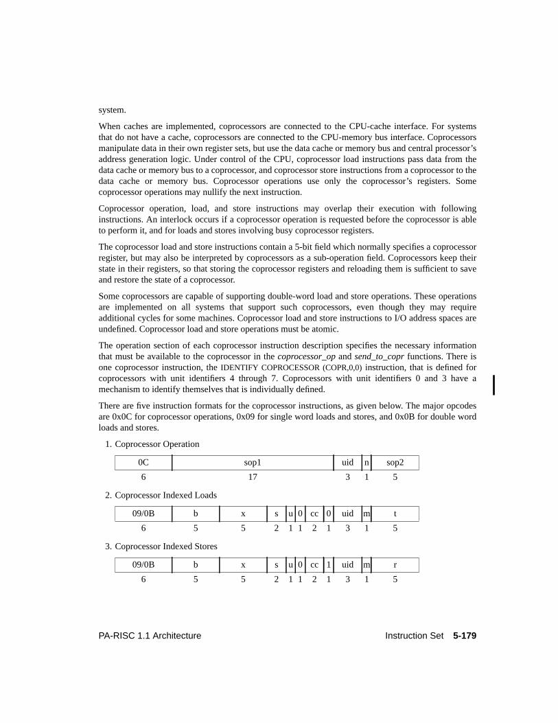
5-179PA-RISC 1.1 Architecture Instruction Set
system.
When caches are implemented, coprocessors are connected to the CPU-cache interface. For systemsthat do not have a cache, coprocessors are connected to the CPU-memory bus interface. Coprocessorsmanipulate data in their own register sets, but use the data cache or memory bus and central processor’saddress generation logic. Under control of the CPU, coprocessor load instructions pass data from thedata cache or memory bus to a coprocessor, and coprocessor store instructions from a coprocessor to thedata cache or memory bus. Coprocessor operations use only the coprocessor’s registers. Somecoprocessor operations may nullify the next instruction.
Coprocessor operation, load, and store instructions may overlap their execution with followinginstructions. An interlock occurs if a coprocessor operation is requested before the coprocessor is ableto perform it, and for loads and stores involving busy coprocessor registers.
The coprocessor load and store instructions contain a 5-bit field which normally specifies a coprocessorregister, but may also be interpreted by coprocessors as a sub-operation field. Coprocessors keep theirstate in their registers, so that storing the coprocessor registers and reloading them is sufficient to saveand restore the state of a coprocessor.
Some coprocessors are capable of supporting double-word load and store operations. These operationsare implemented on all systems that support such coprocessors, even though they may requireadditional cycles for some machines. Coprocessor load and store instructions to I/O address spaces areundefined. Coprocessor load and store operations must be atomic.
The operation section of each coprocessor instruction description specifies the necessary informationthat must be available to the coprocessor in thecoprocessor_op andsend_to_copr functions. There isone coprocessor instruction, theIDENTIFY COPROCESSOR (COPR,0,0) instruction, that is defined forcoprocessors with unit identifiers 4 through 7. Coprocessors with unit identifiers 0 and 3 have amechanism to identify themselves that is individually defined.
There are five instruction formats for the coprocessor instructions, as given below. The major opcodesare 0x0C for coprocessor operations, 0x09 for single word loads and stores, and 0x0B for double wordloads and stores.
1. Coprocessor Operation
2. Coprocessor Indexed Loads
3. Coprocessor Indexed Stores
0C sop1 uid n sop2
6 17 3 1 5
09/0B b x s u 0 cc 0 uid m t
6 5 5 2 1 1 2 1 3 1 5
09/0B b x s u 0 cc 1 uid m r
6 5 5 2 1 1 2 1 3 1 5
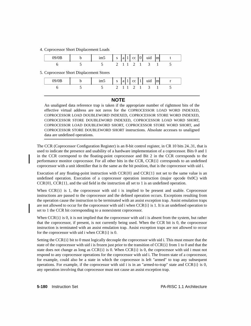
5-180 Instruction Set PA-RISC 1.1 Architecture
4. Coprocessor Short Displacement Loads
5. Coprocessor Short Displacement Stores
NOTEAn unaligned data reference trap is taken if the appropriate number of rightmost bits of theeffective virtual address are not zeros for theCOPROCESSOR LOAD WORD INDEXED,COPROCESSOR LOAD DOUBLEWORD INDEXED, COPROCESSOR STORE WORD INDEXED,COPROCESSOR STORE DOUBLEWORD INDEXED, COPROCESSOR LOAD WORD SHORT,COPROCESSOR LOAD DOUBLEWORD SHORT, COPROCESSOR STORE WORD SHORT, andCOPROCESSOR STORE DOUBLEWORD SHORT instructions. Absolute accesses to unaligneddata are undefined operations.
The CCR (Coprocessor Configuration Register) is an 8-bit control register, in CR 10 bits 24..31, that isused to indicate the presence and usability of a hardware implementation of a coprocessor. Bits 0 and 1in the CCR correspond to the floating-point coprocessor and Bit 2 in the CCR corresponds to theperformance monitor coprocessor. For all other bits in the CCR, CCR{i} corresponds to an undefinedcoprocessor with a unit identifier that is the same as the bit position, that is the coprocessor with uid i.
Execution of any floating-point instruction with CCR{0} and CCR{1} not set to the same value is anundefined operation. Execution of a coprocessor operation instruction (major opcode 0x0C) withCCR{0}, CCR{1}, and the uid field in the instruction all set to 1 is an undefined operation.
When CCR{i} is 1, the coprocessor with uid i is implied to be present and usable. Coprocessorinstructions are passed to the coprocessor and the defined operation occurs. Exceptions resulting fromthe operation cause the instruction to be terminated with an assist exception trap. Assist emulation trapsare not allowed to occur for the coprocessor with uid i when CCR{i} is 1. It is an undefined operation toset to 1 the CCR bit corresponding to a nonexistent coprocessor.
When CCR{i} is 0, it is not implied that the coprocessor with uid i is absent from the system, but ratherthat the coprocessor, if present, is not currently being used. When the CCR bit is 0, the coprocessorinstruction is terminated with an assist emulation trap. Assist exception traps are not allowed to occurfor the coprocessor with uid i when CCR{i} is 0.
Setting the CCR{i} bit to 0 must logically decouple the coprocessor with uid i. This must ensure that thestate of the coprocessor with uid i is frozen just prior to the transition of CCR{i} from 1 to 0 and that thestate does not change as long as CCR{i} is 0. When CCR{i} is 0, the coprocessor with uid i must notrespond to any coprocessor operations for the coprocessor with uid i. The frozen state of a coprocessor,for example, could also be a state in which the coprocessor is left "armed" to trap any subsequentoperations. For example, if the coprocessor with uid i is in an "armed-to-trap" state and CCR{i} is 0,any operation involving that coprocessor must not cause an assist exception trap.
09/0B b im5 s a 1 cc 0 uid m t
6 5 5 2 1 1 2 1 3 1 5
09/0B b im5 s a 1 cc 1 uid m r
6 5 5 2 1 1 2 1 3 1 5
5-181PA-RISC 1.1 Architecture Instruction Set
The precedence of the interruptions that are applicable to operations for the coprocessor with uid idepends on the state of CCR{i}. The assist exception trap and assist emulation trap are always taken inthe priority order as described in “Interruptions” on page 4-13.
NOTELogical decoupling may be accomplished in a variety of ways. Processors may use abortsignals or other schemes to notify coprocessors that the current instruction is to be ignored.
When the CCR bit is 0, logical decoupling suppresses any exception traps from a coprocessorand causes the emulation trap to occur (if it is the highest priority).
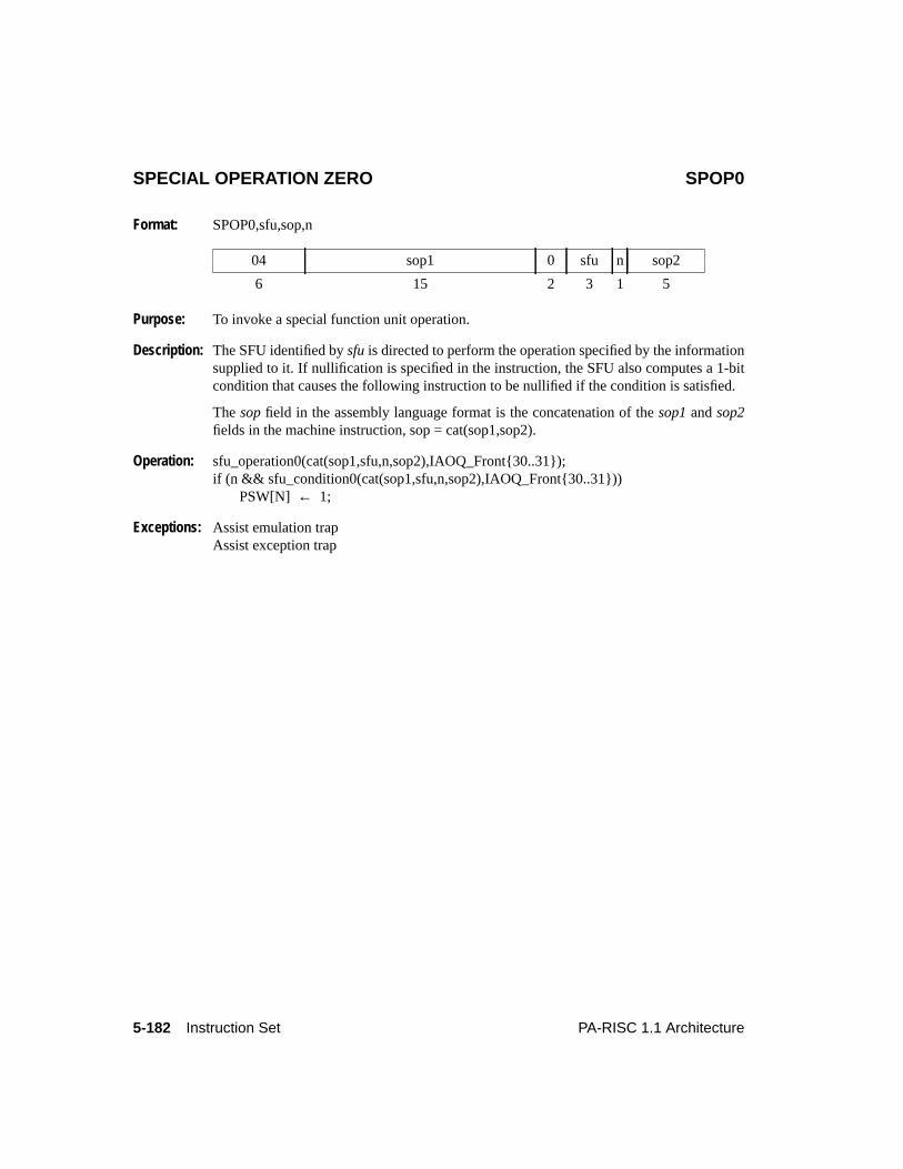
5-182 Instruction Set PA-RISC 1.1 Architecture
SPECIAL OPERATION ZERO SPOP0
Format: SPOP0,sfu,sop,n
Purpose: To invoke a special function unit operation.
Description: The SFU identified bysfu is directed to perform the operation specified by the informationsupplied to it. If nullification is specified in the instruction, the SFU also computes a 1-bitcondition that causes the following instruction to be nullified if the condition is satisfied.
Thesop field in the assembly language format is the concatenation of thesop1 andsop2fields in the machine instruction, sop = cat(sop1,sop2).
Operation: sfu_operation0(cat(sop1,sfu,n,sop2),IAOQ_Front{30..31});if (n && sfu_condition0(cat(sop1,sfu,n,sop2),IAOQ_Front{30..31}))
PSW[N] ← 1;
Exceptions: Assist emulation trapAssist exception trap
04 sop1 0 sfu n sop2
6 15 2 3 1 5
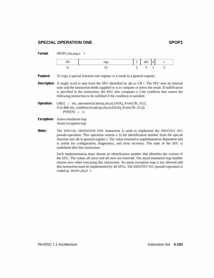
5-183PA-RISC 1.1 Architecture Instruction Set
SPECIAL OPERATION ONE SPOP1
Format: SPOP1,sfu,sop,n t
Purpose: To copy a special function unit register or a result to a general register.
Description: A single word is sent from the SFU identified bysfu to GR t. The SFU uses its internalstate and the instruction fields supplied to it to compute or select the result. If nullificationis specified in the instruction, the SFU also computes a 1-bit condition that causes thefollowing instruction to be nullified if the condition is satisfied.
Operation: GR[t] ← sfu_operation1(cat(sop,sfu,n),IAOQ_Front{30..31});if (n && sfu_condition1(cat(sop,sfu,n),IAOQ_Front{30..31}))
PSW[N] ← 1;
Exceptions: Assist emulation trapAssist exception trap
Notes: The SPECIAL OPERATION ONE instruction is used to implement theIDENTIFY SFUpseudo-operation. This operation returns a 32-bit identification number from the specialfunction unitsfu to general registert. The value returned is implementation dependent andis useful for configuration, diagnostics, and error recovery. The state of the SFU isundefined after this instruction.
Each implementation must choose an identification number that identifies the version ofthe SFU. The values all zeros and all ones are reserved. The assist emulation trap handlerreturns zero when executing this instruction. An assist exception trap is not allowed andthis instruction must be implemented by all SFUs. TheIDENTIFY SFU pseudo-operation iscoded as:SPOP1,sfu,0 t
04 sop 1 sfu n t
6 15 2 3 1 5
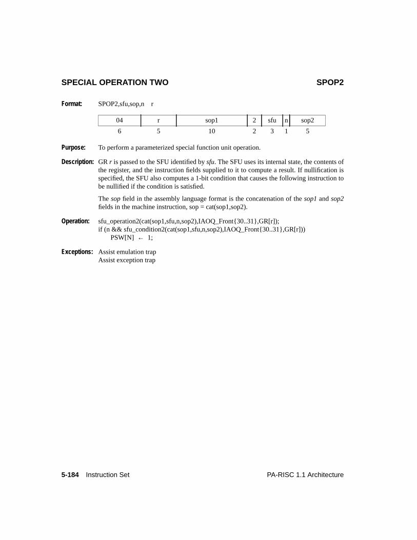
5-184 Instruction Set PA-RISC 1.1 Architecture
SPECIAL OPERATION TWO SPOP2
Format: SPOP2,sfu,sop,n r
Purpose: To perform a parameterized special function unit operation.
Description: GR r is passed to the SFU identified bysfu. The SFU uses its internal state, the contents ofthe register, and the instruction fields supplied to it to compute a result. If nullification isspecified, the SFU also computes a 1-bit condition that causes the following instruction tobe nullified if the condition is satisfied.
Thesop field in the assembly language format is the concatenation of thesop1 andsop2fields in the machine instruction, sop = cat(sop1,sop2).
Operation: sfu_operation2(cat(sop1,sfu,n,sop2),IAOQ_Front{30..31},GR[r]);if (n && sfu_condition2(cat(sop1,sfu,n,sop2),IAOQ_Front{30..31},GR[r]))
PSW[N] ← 1;
Exceptions: Assist emulation trapAssist exception trap
04 r sop1 2 sfu n sop2
6 5 10 2 3 1 5
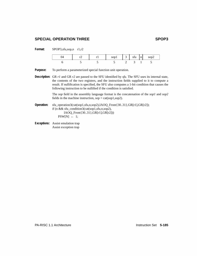
5-185PA-RISC 1.1 Architecture Instruction Set
SPECIAL OPERATION THREE SPOP3
Format: SPOP3,sfu,sop,n r1,r2
Purpose: To perform a parameterized special function unit operation.
Description: GR r1 and GRr2 are passed to the SFU identified bysfu. The SFU uses its internal state,the contents of the two registers, and the instruction fields supplied to it to compute aresult. If nullification is specified, the SFU also computes a 1-bit condition that causes thefollowing instruction to be nullified if the condition is satisfied.
Thesop field in the assembly language format is the concatenation of thesop1 andsop2fields in the machine instruction, sop = cat(sop1,sop2).
Operation: sfu_operation3(cat(sop1,sfu,n,sop2),IAOQ_Front{30..31},GR[r1],GR[r2]);if (n && sfu_condition3(cat(sop1,sfu,n,sop2),
IAOQ_Front{30..31},GR[r1],GR[r2]))PSW[N] ← 1;
Exceptions: Assist emulation trapAssist exception trap
04 r2 r1 sop1 3 sfu n sop2
6 5 5 5 2 3 1 5
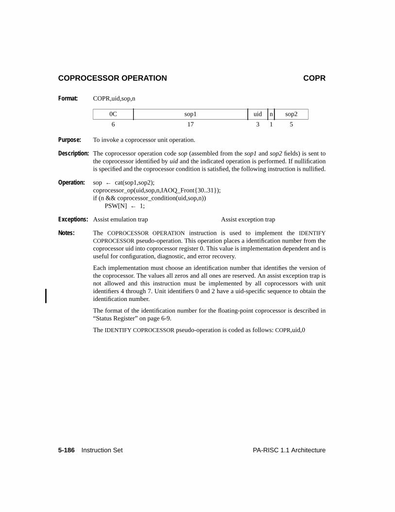
5-186 Instruction Set PA-RISC 1.1 Architecture
COPROCESSOR OPERATION COPR
Format: COPR,uid,sop,n
Purpose: To invoke a coprocessor unit operation.
Description: The coprocessor operation codesop (assembled from thesop1 andsop2 fields) is sent tothe coprocessor identified byuid and the indicated operation is performed. If nullificationis specified and the coprocessor condition is satisfied, the following instruction is nullified.
Operation: sop ← cat(sop1,sop2);coprocessor_op(uid,sop,n,IAOQ_Front{30..31});if (n && coprocessor_condition(uid,sop,n))
PSW[N] ← 1;
Exceptions: Assist emulation trap Assist exception trap
Notes: The COPROCESSOR OPERATION instruction is used to implement theIDENTIFYCOPROCESSOR pseudo-operation. This operation places a identification number from thecoprocessor uid into coprocessor register 0. This value is implementation dependent and isuseful for configuration, diagnostic, and error recovery.
Each implementation must choose an identification number that identifies the version ofthe coprocessor. The values all zeros and all ones are reserved. An assist exception trap isnot allowed and this instruction must be implemented by all coprocessors with unitidentifiers 4 through 7. Unit identifiers 0 and 2 have a uid-specific sequence to obtain theidentification number.
The format of the identification number for the floating-point coprocessor is described in“Status Register” on page 6-9.
TheIDENTIFY COPROCESSOR pseudo-operation is coded as follows:COPR,uid,0
0C sop1 uid n sop2
6 17 3 1 5
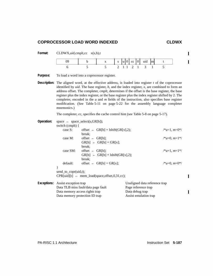
5-187PA-RISC 1.1 Architecture Instruction Set
COPROCESSOR LOAD WORD INDEXED CLDWX
Format: CLDWX,uid,cmplt,cc x(s,b),t
Purpose: To load a word into a coprocessor register.
Description: The aligned word, at the effective address, is loaded into registert of the coprocessoridentified byuid. The base register,b, and the index register,x, are combined to form anaddress offset. The completer,cmplt, determines if the offset is the base register, the baseregister plus the index register, or the base register plus the index register shifted by 2. Thecompleter, encoded in theu andm fields of the instruction, also specifies base registermodification. (See Table 5-11 on page 5-22 for the assembly language completermnemonics.)
The completer,cc, specifies the cache control hint (see Table 5-8 on page 5-17).
Operation: space← space_select(s,GR[b]);switch (cmplt) {
case S: offset← GR[b] + lshift(GR[x],2); /*u=1, m=0*/break;
case M: offset← GR[b]; /*u=0, m=1*/GR[b] ← GR[b] + GR[x];break;
case SM: offset← GR[b]; /*u=1, m=1*/GR[b] ← GR[b] + lshift(GR[x],2);break;
default: offset← GR[b] + GR[x]; /*u=0, m=0*/}send_to_copr(uid,t);CPR[uid][t] ← mem_load(space,offset,0,31,cc);
Exceptions: Assist exception trap Unaligned data reference trapData TLB miss fault/data page fault Page reference trapData memory access rights trap Data debug trapData memory protection ID trap Assist emulation trap
09 b x s u 0 cc 0 uid m t
6 5 5 2 1 1 2 1 3 1 5
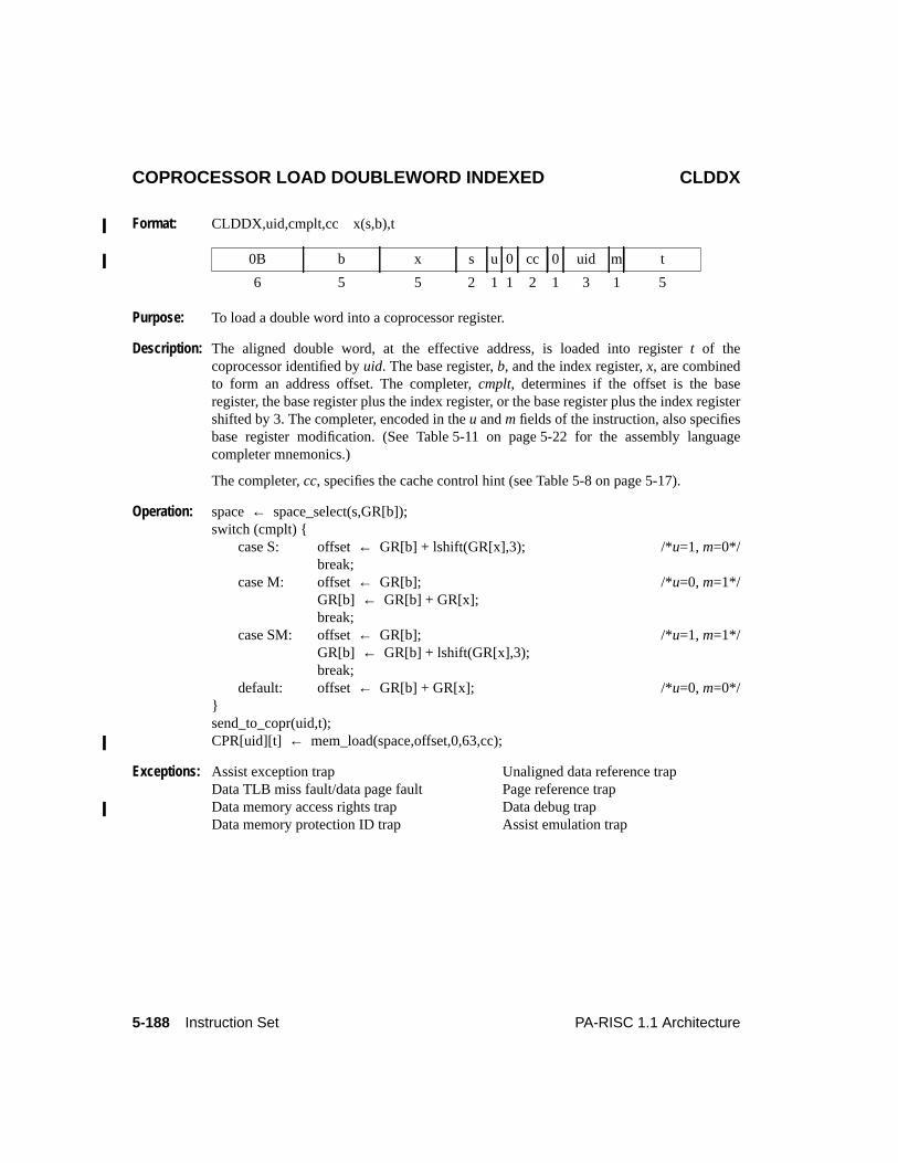
5-188 Instruction Set PA-RISC 1.1 Architecture
COPROCESSOR LOAD DOUBLEWORD INDEXED CLDDX
Format: CLDDX,uid,cmplt,cc x(s,b),t
Purpose: To load a double word into a coprocessor register.
Description: The aligned double word, at the effective address, is loaded into registert of thecoprocessor identified byuid. The base register,b, and the index register,x, are combinedto form an address offset. The completer,cmplt, determines if the offset is the baseregister, the base register plus the index register, or the base register plus the index registershifted by 3. The completer, encoded in theu andm fields of the instruction, also specifiesbase register modification. (See Table 5-11 on page 5-22 for the assembly languagecompleter mnemonics.)
The completer,cc, specifies the cache control hint (see Table 5-8 on page 5-17).
Operation: space← space_select(s,GR[b]);switch (cmplt) {
case S: offset← GR[b] + lshift(GR[x],3); /*u=1, m=0*/break;
case M: offset← GR[b]; /*u=0, m=1*/GR[b] ← GR[b] + GR[x];break;
case SM: offset← GR[b]; /*u=1, m=1*/GR[b] ← GR[b] + lshift(GR[x],3);break;
default: offset← GR[b] + GR[x]; /*u=0, m=0*/}send_to_copr(uid,t);CPR[uid][t] ← mem_load(space,offset,0,63,cc);
Exceptions: Assist exception trap Unaligned data reference trapData TLB miss fault/data page fault Page reference trapData memory access rights trap Data debug trapData memory protection ID trap Assist emulation trap
0B b x s u 0 cc 0 uid m t
6 5 5 2 1 1 2 1 3 1 5
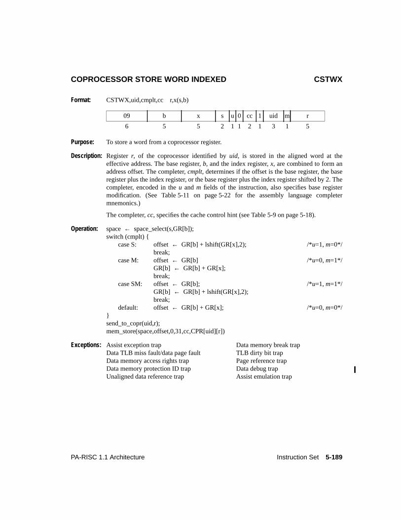
5-189PA-RISC 1.1 Architecture Instruction Set
COPROCESSOR STORE WORD INDEXED CSTWX
Format: CSTWX,uid,cmplt,cc r,x(s,b)
Purpose: To store a word from a coprocessor register.
Description: Registerr, of the coprocessor identified byuid, is stored in the aligned word at theeffective address. The base register,b, and the index register,x, are combined to form anaddress offset. The completer,cmplt, determines if the offset is the base register, the baseregister plus the index register, or the base register plus the index register shifted by 2. Thecompleter, encoded in theu andm fields of the instruction, also specifies base registermodification. (See Table 5-11 on page 5-22 for the assembly language completermnemonics.)
The completer,cc, specifies the cache control hint (see Table 5-9 on page 5-18).
Operation: space← space_select(s,GR[b]);switch (cmplt) {
case S: offset← GR[b] + lshift(GR[x],2); /*u=1, m=0*/break;
case M: offset← GR[b] /*u=0, m=1*/GR[b] ← GR[b] + GR[x];break;
case SM: offset← GR[b]; /*u=1, m=1*/GR[b] ← GR[b] + lshift(GR[x],2);break;
default: offset← GR[b] + GR[x]; /*u=0, m=0*/}send_to_copr(uid,r);mem_store(space,offset,0,31,cc,CPR[uid][r])
Exceptions: Assist exception trap Data memory break trapData TLB miss fault/data page fault TLB dirty bit trapData memory access rights trap Page reference trapData memory protection ID trap Data debug trapUnaligned data reference trap Assist emulation trap
09 b x s u 0 cc 1 uid m r
6 5 5 2 1 1 2 1 3 1 5
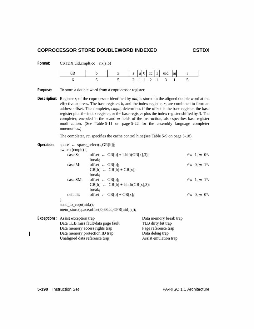
5-190 Instruction Set PA-RISC 1.1 Architecture
COPROCESSOR STORE DOUBLEWORD INDEXED CSTDX
Format: CSTDX,uid,cmplt,cc r,x(s,b)
Purpose: To store a double word from a coprocessor register.
Description: Registerr, of the coprocessor identified byuid, is stored in the aligned double word at theeffective address. The base register,b, and the index register,x, are combined to form anaddress offset. The completer,cmplt, determines if the offset is the base register, the baseregister plus the index register, or the base register plus the index register shifted by 3. Thecompleter, encoded in theu andm fields of the instruction, also specifies base registermodification. (See Table 5-11 on page 5-22 for the assembly language completermnemonics.)
The completer,cc, specifies the cache control hint (see Table 5-9 on page 5-18).
Operation: space← space_select(s,GR[b]);switch (cmplt) {
case S: offset← GR[b] + lshift(GR[x],3); /*u=1, m=0*/break;
case M: offset← GR[b]; /*u=0, m=1*/GR[b] ← GR[b] + GR[x];break;
case SM: offset← GR[b]; /*u=1, m=1*/GR[b] ← GR[b] + lshift(GR[x],3);break;
default: offset← GR[b] + GR[x]; /*u=0, m=0*/}send_to_copr(uid,r);mem_store(space,offset,0,63,cc,CPR[uid][r]);
Exceptions: Assist exception trap Data memory break trapData TLB miss fault/data page fault TLB dirty bit trapData memory access rights trap Page reference trapData memory protection ID trap Data debug trapUnaligned data reference trap Assist emulation trap
0B b x s u 0 cc 1 uid m r
6 5 5 2 1 1 2 1 3 1 5
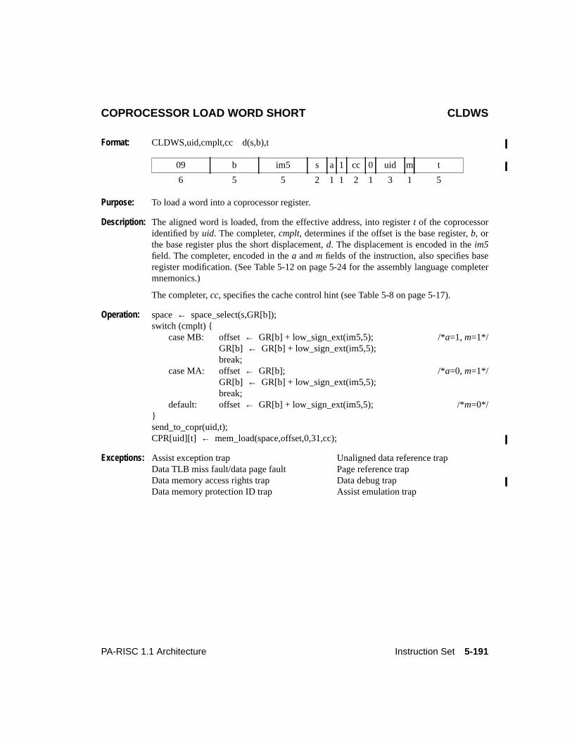
5-191PA-RISC 1.1 Architecture Instruction Set
COPROCESSOR LOAD WORD SHORT CLDWS
Format: CLDWS,uid,cmplt,cc d(s,b),t
Purpose: To load a word into a coprocessor register.
Description: The aligned word is loaded, from the effective address, into registert of the coprocessoridentified byuid. The completer,cmplt, determines if the offset is the base register,b, orthe base register plus the short displacement,d. The displacement is encoded in theim5field. The completer, encoded in thea andm fields of the instruction, also specifies baseregister modification. (See Table 5-12 on page 5-24 for the assembly language completermnemonics.)
The completer,cc, specifies the cache control hint (see Table 5-8 on page 5-17).
Operation: space← space_select(s,GR[b]);switch (cmplt) {
case MB: offset← GR[b] + low_sign_ext(im5,5); /*a=1, m=1*/GR[b] ← GR[b] + low_sign_ext(im5,5);break;
case MA: offset← GR[b]; /*a=0, m=1*/GR[b] ← GR[b] + low_sign_ext(im5,5);break;
default: offset← GR[b] + low_sign_ext(im5,5); /*m=0*/}send_to_copr(uid,t);CPR[uid][t] ← mem_load(space,offset,0,31,cc);
Exceptions: Assist exception trap Unaligned data reference trapData TLB miss fault/data page fault Page reference trapData memory access rights trap Data debug trapData memory protection ID trap Assist emulation trap
09 b im5 s a 1 cc 0 uid m t
6 5 5 2 1 1 2 1 3 1 5
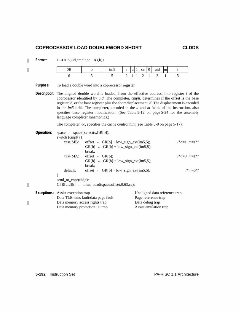
5-192 Instruction Set PA-RISC 1.1 Architecture
COPROCESSOR LOAD DOUBLEWORD SHORT CLDDS
Format: CLDDS,uid,cmplt,cc i(s,b),t
Purpose: To load a double word into a coprocessor register.
Description: The aligned double word is loaded, from the effective address, into registert of thecoprocessor identified byuid. The completer,cmplt, determines if the offset is the baseregister,b, or the base register plus the short displacement,d. The displacement is encodedin the im5 field. The completer, encoded in thea and m fields of the instruction, alsospecifies base register modification. (See Table 5-12 on page 5-24 for the assemblylanguage completer mnemonics.)
The completer,cc, specifies the cache control hint (see Table 5-8 on page 5-17).
Operation: space← space_select(s,GR[b]);switch (cmplt) {
case MB: offset← GR[b] + low_sign_ext(im5,5); /*a=1, m=1*/GR[b] ← GR[b] + low_sign_ext(im5,5);break;
case MA: offset← GR[b]; /*a=0, m=1*/GR[b] ← GR[b] + low_sign_ext(im5,5);break;
default: offset← GR[b] + low_sign_ext(im5,5); /*m=0*/}send_to_copr(uid,t);CPR[uid][t] ← mem_load(space,offset,0,63,cc);
Exceptions: Assist exception trap Unaligned data reference trapData TLB miss fault/data page fault Page reference trapData memory access rights trap Data debug trapData memory protection ID trap Assist emulation trap
0B b im5 s a 1 cc 0 uid m t
6 5 5 2 1 1 2 1 3 1 5
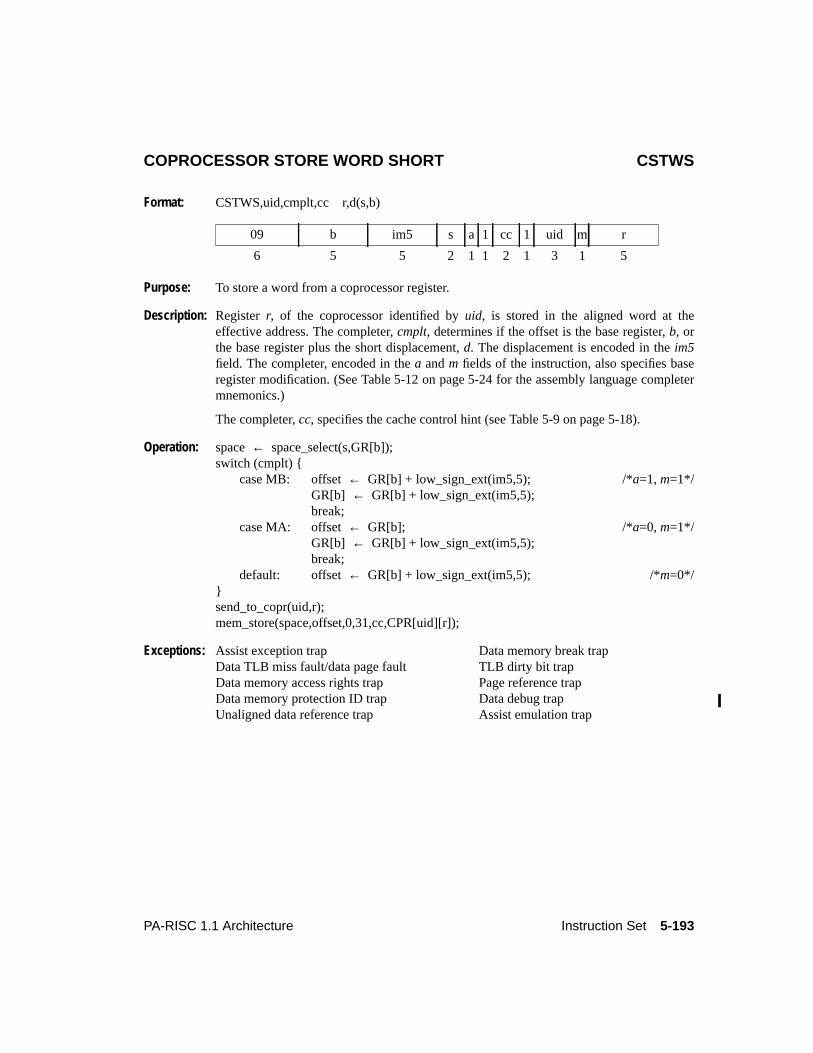
5-193PA-RISC 1.1 Architecture Instruction Set
COPROCESSOR STORE WORD SHORT CSTWS
Format: CSTWS,uid,cmplt,cc r,d(s,b)
Purpose: To store a word from a coprocessor register.
Description: Registerr, of the coprocessor identified byuid, is stored in the aligned word at theeffective address. The completer,cmplt, determines if the offset is the base register,b, orthe base register plus the short displacement,d. The displacement is encoded in theim5field. The completer, encoded in thea andm fields of the instruction, also specifies baseregister modification. (See Table 5-12 on page 5-24 for the assembly language completermnemonics.)
The completer,cc, specifies the cache control hint (see Table 5-9 on page 5-18).
Operation: space← space_select(s,GR[b]);switch (cmplt) {
case MB: offset← GR[b] + low_sign_ext(im5,5); /*a=1, m=1*/GR[b] ← GR[b] + low_sign_ext(im5,5);break;
case MA: offset← GR[b]; /*a=0, m=1*/GR[b] ← GR[b] + low_sign_ext(im5,5);break;
default: offset← GR[b] + low_sign_ext(im5,5); /*m=0*/}send_to_copr(uid,r);mem_store(space,offset,0,31,cc,CPR[uid][r]);
Exceptions: Assist exception trap Data memory break trapData TLB miss fault/data page fault TLB dirty bit trapData memory access rights trap Page reference trapData memory protection ID trap Data debug trapUnaligned data reference trap Assist emulation trap
09 b im5 s a 1 cc 1 uid m r
6 5 5 2 1 1 2 1 3 1 5
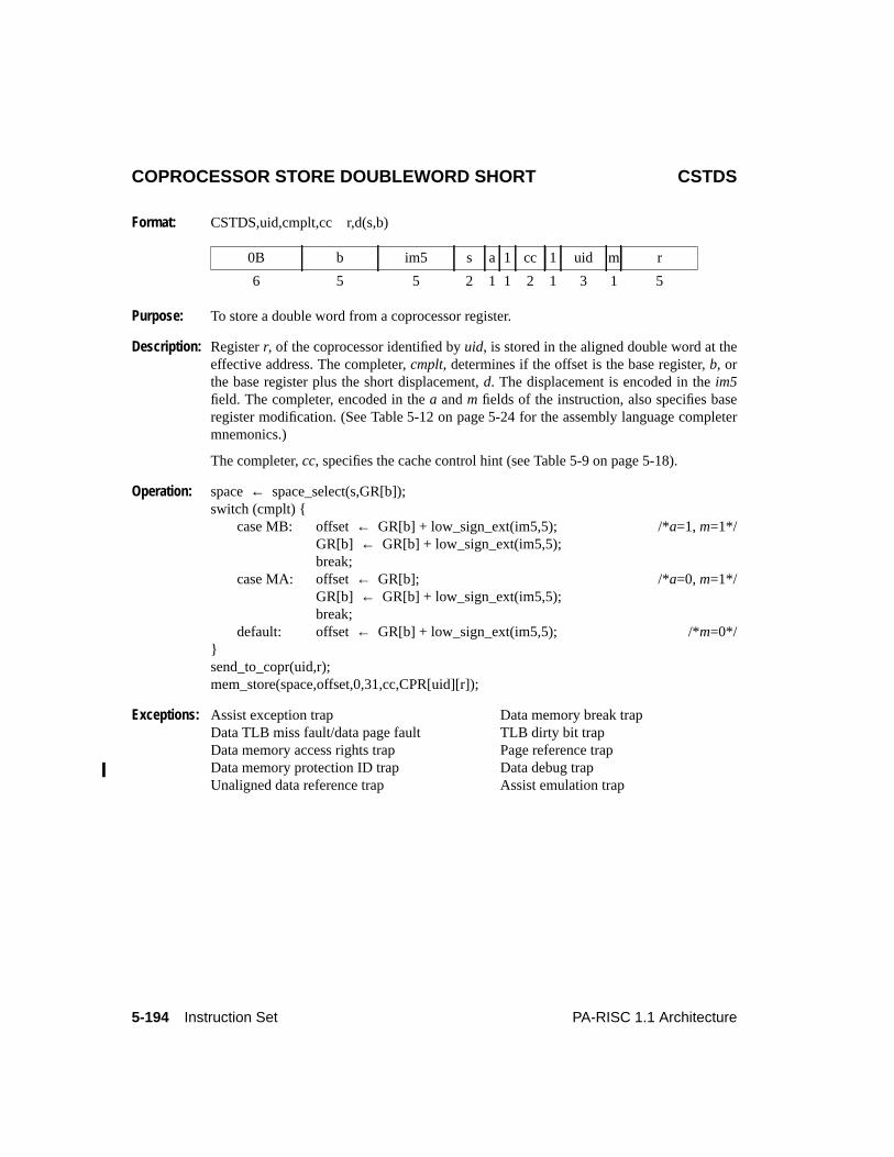
5-194 Instruction Set PA-RISC 1.1 Architecture
COPROCESSOR STORE DOUBLEWORD SHORT CSTDS
Format: CSTDS,uid,cmplt,cc r,d(s,b)
Purpose: To store a double word from a coprocessor register.
Description: Registerr, of the coprocessor identified byuid, is stored in the aligned double word at theeffective address. The completer,cmplt, determines if the offset is the base register,b, orthe base register plus the short displacement,d. The displacement is encoded in theim5field. The completer, encoded in thea andm fields of the instruction, also specifies baseregister modification. (See Table 5-12 on page 5-24 for the assembly language completermnemonics.)
The completer,cc, specifies the cache control hint (see Table 5-9 on page 5-18).
Operation: space← space_select(s,GR[b]);switch (cmplt) {
case MB: offset← GR[b] + low_sign_ext(im5,5); /*a=1, m=1*/GR[b] ← GR[b] + low_sign_ext(im5,5);break;
case MA: offset← GR[b]; /*a=0, m=1*/GR[b] ← GR[b] + low_sign_ext(im5,5);break;
default: offset← GR[b] + low_sign_ext(im5,5); /*m=0*/}send_to_copr(uid,r);mem_store(space,offset,0,31,cc,CPR[uid][r]);
Exceptions: Assist exception trap Data memory break trapData TLB miss fault/data page fault TLB dirty bit trapData memory access rights trap Page reference trapData memory protection ID trap Data debug trapUnaligned data reference trap Assist emulation trap
0B b im5 s a 1 cc 1 uid m r
6 5 5 2 1 1 2 1 3 1 5
6-1PA-RISC 1.1 Architecture Floating-point Coprocessor
6 Floating-point Coprocessor
IntroductionThis chapter describes the architecture for the floating-point coprocessor.
The PA-RISC floating-point coprocessor is an assist processor that is added to a system to improve thesystem’s performance on floating-point operations. The floating-point coprocessor contains a registerfile which is independent of the processor’s register file. The floating-point coprocessor executesfloating-point instructions to perform arithmetic on this register file and to move data between theregister file and memory. The architecture permits pipelined execution of floating-point instructions,further increasing the system’s performance.
Floating-point instructions are implementations of the more general coprocessor instructions describedpreviously in Chapter 5, “Instruction Set”. The floating-point coprocessor responds to coprocessorinstructions with a coprocessor id equal to 0 and 1.
While the floating-point coprocessor is not required to execute instructions sequentially, the coprocessorand processor must ensure that the instructions appear sequentially executed to the software. At any onetime, the processor and coprocessor may be operating on a number of instructions. For purposes of thischapter, thecurrent instruction is the instruction pointed to by the IA queues. The termpendinginstructions refers to instructions which have entered and left the IA queues, but which the coprocessoris still executing.
The IEEE Standard
When used in this chapter, the termIEEE standard or simply the standard, refers to theIEEEStandard for Binary Floating-Point Arithmetic, ANSI/IEEE Std 754-1985. PA-RISC fully conforms tothe requirements of the IEEE floating-point standard and permits implementation of all IEEE floating-point recommendations. Where hardware is unable to fully implement the standard, software completesthe implementation.
Though this chapter uses quotes from the IEEE standard as architecture, knowledge of the standard isnot necessary to understand the architecture. Whenever a quote of the standard contains a reference toanother part of the standard, the quote also contains an equivalent reference to a section of thisdocument. In these quotes, a reference to the IEEE standard is enclosed in parentheses, and theequivalent reference to this document is enclosed in square brackets.
The Instruction Set
The floating-point instruction set consists of load and store instructions, and operations. Floating-pointload and store instructions copy both single-word and double-word data between memory and thefloating-point registers. Floating-point operations do arithmetic on the floating-point registers and copydata between floating-point registers.
The floating-point coprocessor operates on single-word and double-word IEEE floating-point numbers,
6-2 Floating-point Coprocessor PA-RISC 1.1 Architecture
as well as quad-word numbers, which are an implementation of the IEEE double-extended format. Eachtype of floating-point number may represent one of the following: a normalized number, a denormalizednumber, a zero, an infinity, or a NaN (Not a Number). These floating-point formats consist of a sign bit,an exponent, and a fraction.
The instruction set also has operations that convert among the three formats of floating-point numbersand between floating-point numbers and single-word, double-word, and quad-word two’s complementintegers, as well as an instruction which multiplies two 32-bit unsigned integers with a 64-bit unsignedinteger result.
Coprocessor Registers
The coprocessor contains thirty-two 64-bit floating-point registers. These same 32 locations can be usedas sixty-four 32-bit locations or as sixteen 128-bit locations. Instructions executing at any privilegelevel may read or write the floating-point registers. Double-word load/store operations access the entire64-bit register; single-word load/stores access either the left portion of a 64-bit register, bits 0 to 31, orthe right portion of a 64-bit register, bits 32 to 63.
By convention, a 32-bit floating-point register is identified by appending a suffix to the identifier of the64-bit register within which it is contained. The suffix for the left hand side 32-bit register is ‘L’; the useof this suffix is optional. The suffix for the right hand side 32-bit register is ‘R’; its use isnot optional.Thus, for example, the left half of double-word register 13 (bits 0 to 31) would be referred to as either13 or 13L; the right half of double-word register 13 (bits 32 to 63) would be referred to as 13R. Thespecification ‘L’ or ‘R’ for each register is encoded in the instructions that access these registers.
Table 6-1 illustrates the specification of single-word registers and Table 6-2 illustrates the specificationof double-word registers.
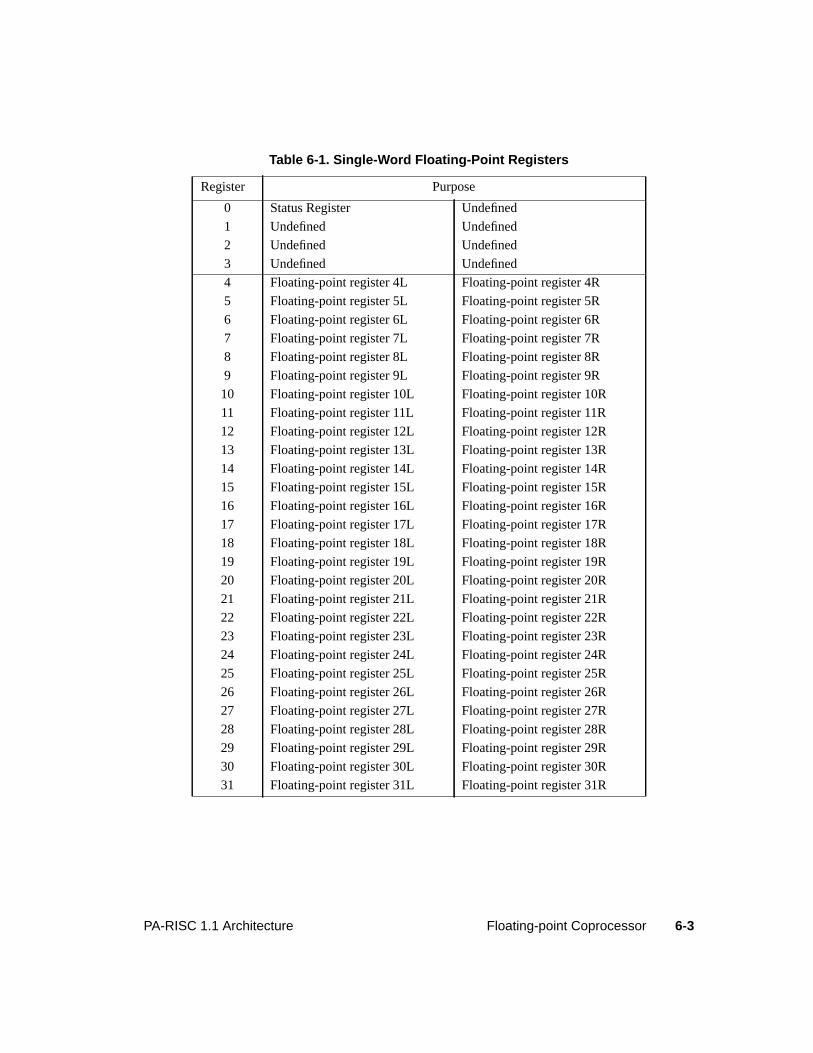
6-3PA-RISC 1.1 Architecture Floating-point Coprocessor
Table 6-1. Single-Word Floating-Point Registers
Register Purpose
0 Status Register Undefined
1 Undefined Undefined
2 Undefined Undefined
3 Undefined Undefined
4 Floating-point register 4L Floating-point register 4R
5 Floating-point register 5L Floating-point register 5R
6 Floating-point register 6L Floating-point register 6R
7 Floating-point register 7L Floating-point register 7R
8 Floating-point register 8L Floating-point register 8R
9 Floating-point register 9L Floating-point register 9R
10 Floating-point register 10L Floating-point register 10R
11 Floating-point register 11L Floating-point register 11R
12 Floating-point register 12L Floating-point register 12R
13 Floating-point register 13L Floating-point register 13R
14 Floating-point register 14L Floating-point register 14R
15 Floating-point register 15L Floating-point register 15R
16 Floating-point register 16L Floating-point register 16R
17 Floating-point register 17L Floating-point register 17R
18 Floating-point register 18L Floating-point register 18R
19 Floating-point register 19L Floating-point register 19R
20 Floating-point register 20L Floating-point register 20R
21 Floating-point register 21L Floating-point register 21R
22 Floating-point register 22L Floating-point register 22R
23 Floating-point register 23L Floating-point register 23R
24 Floating-point register 24L Floating-point register 24R
25 Floating-point register 25L Floating-point register 25R
26 Floating-point register 26L Floating-point register 26R
27 Floating-point register 27L Floating-point register 27R
28 Floating-point register 28L Floating-point register 28R
29 Floating-point register 29L Floating-point register 29R
30 Floating-point register 30L Floating-point register 30R
31 Floating-point register 31L Floating-point register 31R
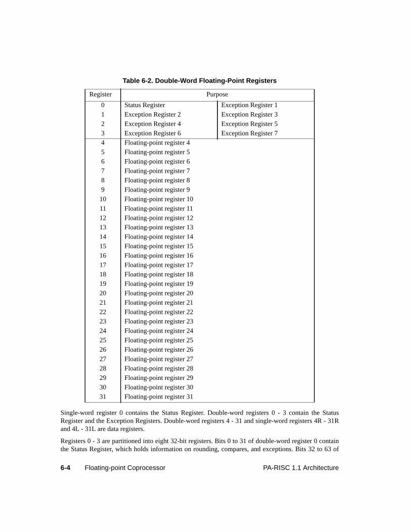
6-4 Floating-point Coprocessor PA-RISC 1.1 Architecture
Single-word register 0 contains the Status Register. Double-word registers 0 - 3 contain the StatusRegister and the Exception Registers. Double-word registers 4 - 31 and single-word registers 4R - 31Rand 4L - 31L are data registers.
Registers 0 - 3 are partitioned into eight 32-bit registers. Bits 0 to 31 of double-word register 0 containthe Status Register, which holds information on rounding, compares, and exceptions. Bits 32 to 63 of
Table 6-2. Double-Word Floating-Point Registers
Register Purpose
0 Status Register Exception Register 1
1 Exception Register 2 Exception Register 3
2 Exception Register 4 Exception Register 5
3 Exception Register 6 Exception Register 7
4 Floating-point register 4
5 Floating-point register 5
6 Floating-point register 6
7 Floating-point register 7
8 Floating-point register 8
9 Floating-point register 9
10 Floating-point register 10
11 Floating-point register 11
12 Floating-point register 12
13 Floating-point register 13
14 Floating-point register 14
15 Floating-point register 15
16 Floating-point register 16
17 Floating-point register 17
18 Floating-point register 18
19 Floating-point register 19
20 Floating-point register 20
21 Floating-point register 21
22 Floating-point register 22
23 Floating-point register 23
24 Floating-point register 24
25 Floating-point register 25
26 Floating-point register 26
27 Floating-point register 27
28 Floating-point register 28
29 Floating-point register 29
30 Floating-point register 30
31 Floating-point register 31
6-5PA-RISC 1.1 Architecture Floating-point Coprocessor
double-word register 0 contain Exception Register 1. Specifying Floating-point Register 0 in a non-load/store operation encodes a floating-point +0 or a fixed-point 0, whichever is appropriate, when usedas a source and is an undefined operation when used as a destination.
Double-word registers 1 to 3 contain the remaining exception registers. The exception registers form aqueue of instructions which could not normally complete and thus complete with a trapping exception.The exception registers are accessed using double-word load and store instructions. Single-word loadsand stores of exception registers are undefined operations. Specifying an exception register as a sourceor destination of a non-load/store operation is undefined.
A special instruction sequence saves and restores the state of the coprocessor. This sequence ensuresthat context switches and other operations which affect the state of the coprocessor do not affect aprocess.
ExceptionsFloating-point instructions may cause an interruption in the processor, an exception in the coprocessor,or both. Interruptions are described in Chapter 4, “Flow Control and Interruptions” and always force theprocessor to branch to a location in the Interruption Vector Table. Floating-point coprocessor exceptionsmay or may not force the processor to trap (that is, force the processor to take an interruption). In thischapter, an instruction which causes a floating-point exception is called anexcepting instruction.
Floating-point exceptions are divided into immediate trapping exceptions and delayed trappingexceptions. Immediate trapping exceptions always force the processor to trap. Delayed trappingexceptions are further divided into exceptions that always trap, and exceptions that will trap only whenthe corresponding trap is enabled. An immediate trapping exception forces the processor to signal anassist exception trap when the excepting instruction is the current instruction being executed. A delayedtrapping exception forces the processor to signal an assist exception trap when the current instruction isa floating-point instruction, but the excepting instruction is a pending instruction.
The only immediate trapping exception is the reserved-op exception. This exception cannot be disabled.
The only delayed trapping exception that cannot be disabled is the unimplemented exception. The otherdelayed trapping exceptions are the IEEE exceptions. Each has a corresponding bit in the StatusRegister which enables and disables the delayed trap. The IEEE exceptions are the following: invalidoperation, division-by-zero, overflow, underflow, and inexact.
Data RegistersFloating-point registers 4 - 31 contain the 64-bit data registers which instructions use as operands.Software may access these registers with single-word or double-word load and store instructions.
Each of the floating-point data registers may contain values in a number of formats. The fields in theseformats are packed into words, double-words, or quad-words so that load and store operations do notrequire field-shuffling or tag bits.
Single-word formats occupy either the left half (bits 0 to 31, suffix ’L’), or the right half (bits 32 to 63,suffix ’R’) of a register as shown in Figure 6-1.
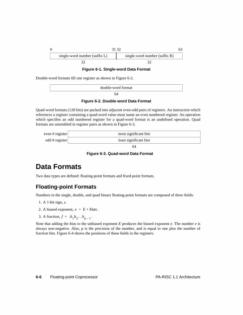
6-6 Floating-point Coprocessor PA-RISC 1.1 Architecture
Double-word formats fill one register as shown in Figure 6-2.
Quad-word formats (128 bits) are packed into adjacent even-odd pairs of registers. An instruction whichreferences a register containing a quad-word value must name an even numbered register. An operationwhich specifies an odd numbered register for a quad-word format is an undefined operation. Quadformats are assembled in register pairs as shown in Figure 6-3.
Data FormatsTwo data types are defined: floating-point formats and fixed-point formats.
Floating-point FormatsNumbers in the single, double, and quad binary floating-point formats are composed of three fields:
1. A 1-bit sign,s.
2. A biased exponent, .
3. A fraction, .
Note that adding thebias to the unbiased exponentE produces the biased exponente. The numbere isalways non-negative. Also,p is the precision of the number, and is equal to one plus the number offraction bits. Figure 6-4 shows the positions of these fields in the registers.
0 31 32 63
single-word number (suffix L) single-word number (suffix R)
32 32
Figure 6-1. Single-word Data Format
double-word format
64
Figure 6-2. Double-word Data Format
even # register most significant bits
odd # register least significant bits
64
Figure 6-3. Quad-word Data Format
e E bias+=
f .b1b2…bp 1–=
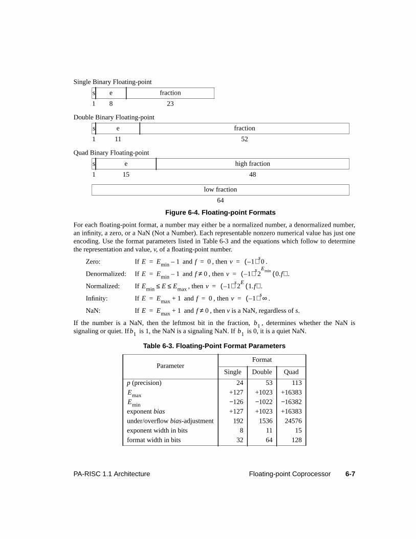
6-7PA-RISC 1.1 Architecture Floating-point Coprocessor
Single Binary Floating-point
Double Binary Floating-point
Quad Binary Floating-point
For each floating-point format, a number may either be a normalized number, a denormalized number,an infinity, a zero, or a NaN (Not a Number). Each representable nonzero numerical value has just oneencoding. Use the format parameters listed in Table 6-3 and the equations which follow to determinethe representation and value,v, of a floating-point number.
Zero: If and , then .
Denormalized: If and , then .
Normalized: If , then .
Infinity: If and , then .
NaN: If and , thenv is a NaN, regardless ofs.
If the number is a NaN, then the leftmost bit in the fraction, , determines whether the NaN issignaling or quiet. If is 1, the NaN is a signaling NaN. If is 0, it is a quiet NaN.
s e fraction
1 8 23
s e fraction
1 11 52
s e high fraction
1 15 48
low fraction
64
Figure 6-4. Floating-point Formats
Table 6-3. Floating-Point Format Parameters
ParameterFormat
Single Double Quad
p (precision) 24 53 113
+127 +1023 +16383
−126 −1022 −16382
exponentbias +127 +1023 +16383
under/overflowbias-adjustment 192 1536 24576
exponent width in bits 8 11 15
format width in bits 32 64 128
E Emin 1–= f 0= v 1–( ) s0=
E Emin 1–= f 0≠ v 1–( ) s2
Emin0.f( )=
Emin E Emax≤ ≤ v 1–( ) s2
E1.f( )=
E Emax 1+= f 0= v 1–( ) s∞=
E Emax 1+= f 0≠
b1b1 b1
EmaxEmin
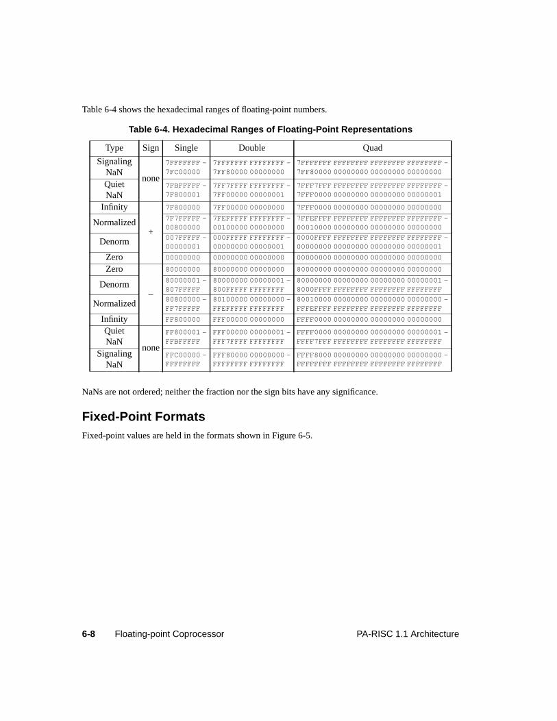
6-8 Floating-point Coprocessor PA-RISC 1.1 Architecture
Table 6-4 shows the hexadecimal ranges of floating-point numbers.
NaNs are not ordered; neither the fraction nor the sign bits have any significance.
Fixed-Point FormatsFixed-point values are held in the formats shown in Figure 6-5.
Table 6-4. Hexadecimal Ranges of Floating-Point Representations
Type Sign Single Double Quad
SignalingNaN
none
7FFFFFFF -7FC00000
7FFFFFFF FFFFFFFF -7FF80000 00000000
7FFFFFFF FFFFFFFF FFFFFFFF FFFFFFFF -7FF80000 00000000 00000000 00000000
QuietNaN
7FBFFFFF -7F800001
7FF7FFFF FFFFFFFF -7FF00000 00000001
7FFF7FFF FFFFFFFF FFFFFFFF FFFFFFFF -7FFF0000 00000000 00000000 00000001
Infinity
+
7F800000 7FF00000 00000000 7FFF0000 00000000 00000000 00000000
Normalized 7F7FFFFF -00800000
7FEFFFFF FFFFFFFF -00100000 00000000
7FFEFFFF FFFFFFFF FFFFFFFF FFFFFFFF -00010000 00000000 00000000 00000000
Denorm 007FFFFF -00000001
000FFFFF FFFFFFFF -00000000 00000001
0000FFFF FFFFFFFF FFFFFFFF FFFFFFFF -00000000 00000000 00000000 00000001
Zero 00000000 00000000 00000000 00000000 00000000 00000000 00000000
Zero
–
80000000 80000000 00000000 80000000 00000000 00000000 00000000
Denorm 80000001 -807FFFFF
80000000 00000001 -800FFFFF FFFFFFFF
80000000 00000000 00000000 00000001 -8000FFFF FFFFFFFF FFFFFFFF FFFFFFFF
Normalized 80800000 -FF7FFFFF
80100000 00000000 -FFEFFFFF FFFFFFFF
80010000 00000000 00000000 00000000 -FFFEFFFF FFFFFFFF FFFFFFFF FFFFFFFF
Infinity FF800000 FFF00000 00000000 FFFF0000 00000000 00000000 00000000
QuietNaN
none
FF800001 -FFBFFFFF
FFF00000 00000001 -FFF7FFFF FFFFFFFF
FFFF0000 00000000 00000000 00000001 -FFFF7FFF FFFFFFFF FFFFFFFF FFFFFFFF
SignalingNaN
FFC00000 -FFFFFFFF
FFF80000 00000000 -FFFFFFFF FFFFFFFF
FFFF8000 00000000 00000000 00000000 -FFFFFFFF FFFFFFFF FFFFFFFF FFFFFFFF
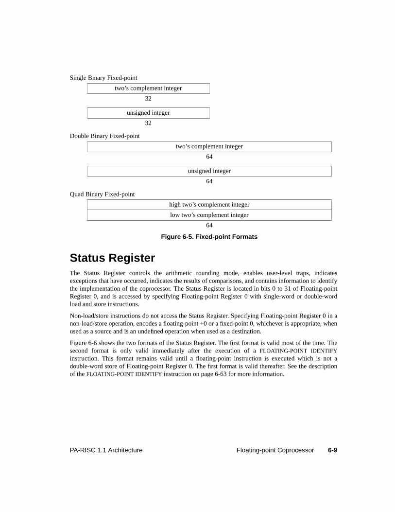
6-9PA-RISC 1.1 Architecture Floating-point Coprocessor
Single Binary Fixed-point
Double Binary Fixed-point
Quad Binary Fixed-point
Status RegisterThe Status Register controls the arithmetic rounding mode, enables user-level traps, indicatesexceptions that have occurred, indicates the results of comparisons, and contains information to identifythe implementation of the coprocessor. The Status Register is located in bits 0 to 31 of Floating-pointRegister 0, and is accessed by specifying Floating-point Register 0 with single-word or double-wordload and store instructions.
Non-load/store instructions do not access the Status Register. Specifying Floating-point Register 0 in anon-load/store operation, encodes a floating-point +0 or a fixed-point 0, whichever is appropriate, whenused as a source and is an undefined operation when used as a destination.
Figure 6-6 shows the two formats of the Status Register. The first format is valid most of the time. Thesecond format is only valid immediately after the execution of aFLOATING-POINT IDENTIFYinstruction. This format remains valid until a floating-point instruction is executed which is not adouble-word store of Floating-point Register 0. The first format is valid thereafter. See the descriptionof theFLOATING-POINT IDENTIFY instruction on page 6-63 for more information.
two’s complement integer
32
unsigned integer
32
two’s complement integer
64
unsigned integer
64
high two’s complement integer
low two’s complement integer
64
Figure 6-5. Fixed-point Formats
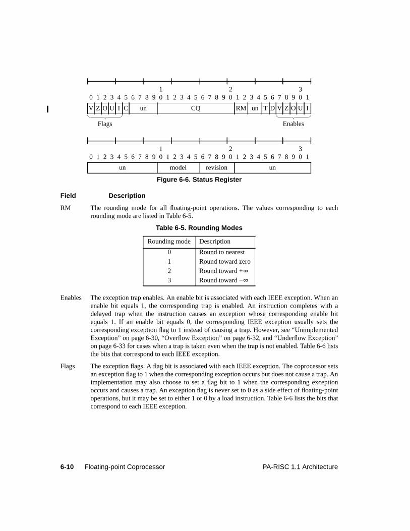
6-10 Floating-point Coprocessor PA-RISC 1.1 Architecture
Field Description
RM The rounding mode for all floating-point operations. The values corresponding to eachrounding mode are listed in Table 6-5.
Enables The exception trap enables. An enable bit is associated with each IEEE exception. When anenable bit equals 1, the corresponding trap is enabled. An instruction completes with adelayed trap when the instruction causes an exception whose corresponding enable bitequals 1. If an enable bit equals 0, the corresponding IEEE exception usually sets thecorresponding exception flag to 1 instead of causing a trap. However, see “UnimplementedException” on page 6-30, “Overflow Exception” on page 6-32, and “Underflow Exception”on page 6-33 for cases when a trap is taken even when the trap is not enabled. Table 6-6 liststhe bits that correspond to each IEEE exception.
Flags The exception flags. A flag bit is associated with each IEEE exception. The coprocessor setsan exception flag to 1 when the corresponding exception occurs but does not cause a trap. Animplementation may also choose to set a flag bit to 1 when the corresponding exceptionoccurs and causes a trap. An exception flag is never set to 0 as a side effect of floating-pointoperations, but it may be set to either 1 or 0 by a load instruction. Table 6-6 lists the bits thatcorrespond to each IEEE exception.
0 1 2 3 4 5 6 7 8 910 1 2 3 4 5 6 7 8 9
20 1 2 3 4 5 6 7 8 9
30 1
V Z O U I C un CQ RM un T D V Z O U I
0 1 2 3 4 5 6 7 8 910 1 2 3 4 5 6 7 8 9
20 1 2 3 4 5 6 7 8 9
30 1
un model revision un
Figure 6-6. Status Register
Table 6-5. Rounding Modes
Rounding mode Description
0 Round to nearest
1 Round toward zero
2 Round toward +∞3 Round toward−∞
Flags Enables
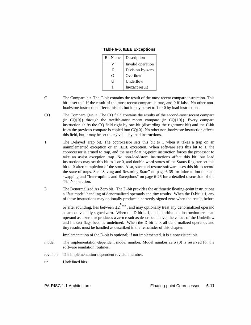
6-11PA-RISC 1.1 Architecture Floating-point Coprocessor
C The Compare bit. The C-bit contains the result of the most recent compare instruction. Thisbit is set to 1 if the result of the most recent compare is true, and 0 if false. No other non-load/store instruction affects this bit, but it may be set to 1 or 0 by load instructions.
CQ The Compare Queue. The CQ field contains the results of the second-most recent compare(in CQ{0}) through the twelfth-most recent compare (in CQ{10}). Every compareinstruction shifts the CQ field right by one bit (discarding the rightmost bit) and the C-bitfrom the previous compare is copied into CQ{0}. No other non-load/store instruction affectsthis field, but it may be set to any value by load instructions.
T The Delayed Trap bit. The coprocessor sets this bit to 1 when it takes a trap on anunimplemented exception or an IEEE exception. When software sets this bit to 1, thecoprocessor is armed to trap, and the next floating-point instruction forces the processor totake an assist exception trap. No non-load/store instructions affect this bit, but loadinstructions may set this bit to 1 or 0, and double-word stores of the Status Register set thisbit to 0 after completion of the store. Also, save and restore software uses this bit to recordthe state of traps. See “Saving and Restoring State” on page 6-35 for information on stateswapping and “Interruptions and Exceptions” on page 6-26 for a detailed discussion of theT-bit’s operation.
D The Denormalized As Zero bit. The D-bit provides the arithmetic floating-point instructionsa “fast mode” handling of denormalized operands and tiny results. When the D-bit is 1, anyof these instructions may optionally produce a correctly signed zero when the result, before
or after rounding, lies between , and may optionally treat any denormalized operandas an equivalently signed zero. When the D-bit is 1, and an arithmetic instruction treats anoperand as a zero, or produces a zero result as described above, the values of the Underflowand Inexact flags become undefined. When the D-bit is 0, all denormalized operands andtiny results must be handled as described in the remainder of this chapter.
Implementation of the D-bit is optional; if not implemented, it is a nonexistent bit.
model The implementation-dependent model number. Model number zero (0) is reserved for thesoftware emulation routines.
revision The implementation-dependent revision number.
un Undefined bits.
Table 6-6. IEEE Exceptions
Bit Name Description
V Invalid operation
Z Division-by-zero
O Overflow
U Underflow
I Inexact result
2Emin±
6-12 Floating-point Coprocessor PA-RISC 1.1 Architecture
Instruction SetThe floating-point instruction set consists of load and store instructions, and floating-point operations.All these instructions are part of the PA-RISC standard instruction set. When the instruction specifies aregister for double precision and 64-bit fixed-point values, a 5-bit encoding maps directly into theassociated floating-point register. When the instruction specifies a register for single-precision or 32-bitfixed-point values, a 6-bit encoding maps into the appropriate ‘L’ or ‘R’ single-word floating-pointregister.
Instruction ValidityTable 6-7 shows which floating-point instructions are defined, undefined, or will take an AssistEmulation Trap for various values of the uid field and the Coprocessor Configuration Register.
Load and Store InstructionsThe floating-point load and store instructions are implementations of the PA-RISC coprocessor load andstore instructions described in “Coprocessor Instructions” on page 5-178. Table 6-8 shows the floating-point load and store instructions.
The load and store instructions transfer data between the floating-point registers and memory. Theseinstructions transfer aligned words or aligned double-words, and use either a short displacement valueor the value of an index register. They also have completers that specify base register modification andcache control hints.
Table 6-7. Floating-Point Instruction Validity
OpcodeCCR{0..1}
0 1, 2 3
0B/0C trap undefined uid=0: defineduid=1: undefined
06/09/0E/26 trap undefined defined
Table 6-8. Floating-Point Load and Store Instructions
Mnemonic Description
FLDWX Load word using index register
FLDDX Load doubleword using index register
FSTWX Store word using index register
FSTDX Store doubleword using index register
FLDWS Load word using short displacement
FLDDS Load doubleword using short displacement
FSTWS Store word using short displacement
FSTDS Store doubleword using short displacement
6-13PA-RISC 1.1 Architecture Floating-point Coprocessor
Single-word loads and stores access either bits 0 to 31 (suffix ‘L’) or bits 32 to 63 (suffix ‘R’) of aregister. The ability to specify more than 32 locations is accomplished by the use of bit 25 of theinstruction. A 0 in this bit specifies an access of bits 0 to 31 (left half of the register); a 1 specifies anaccess of bits 32 to 63 (the right half of the register). However, single-word loads and stores of floating-point registers 0R (the right half of floating-point register 0), 1, 2, and 3 are undefined operations.
Double-word loads and stores can access any of the floating-point registers and may be used to load orstore a pair of single-word values in the left and right halves of a register.
A single-word or double-word load or store of Floating-point Register 0 forces the coprocessor tocomplete all pending floating-point instructions and signal all floating-point exceptions for thoseinstructions. Additionally, a double-word store of Floating-point Register 0 cancels traps due to allprevious instructions and, after completion of the store, sets the Status Register T-bit to 0.
Single-word stores of register 0 do not cancel traps. Also, single-word loads of register 0 that set theStatus Register T-bit to 1 are undefined operations.
A double-word load or store of registers 1, 2 or 3 forces the floating-point coprocessor to complete allprevious instructions that may update the specified exception register.
Load and store instructions may cause a number of memory reference traps. They are not arithmeticinstructions and do not cause IEEE exceptions.
Load and store instructions that access the I/O address space are undefined operations.
Floating-point OperationsThere are two categories of floating-point operation instructions. Each instruction in the first categoryperforms a single operation. Instructions in the second category perform multiple operations.
Single-operation Instructions
This section describes the single-operation floating-point instructions. Single-operation floating-pointinstructions are encoded using two major opcodes - 0C and 0E. Most of the functions in the 0C opcodeare also duplicated in the 0E opcode with the following exceptions:
• Instructions using the 0E opcode can address both the left and right halves of the floating-pointregister set whereas the instructions using the 0C opcode can only address the left halves of thefloating-point register set.
• TheCOPR,0,0 andFTEST instructions are available only in the 0C opcode.
• The format completer for the quad-word data type cannot be specified for the 0E opcode.
• TheXMPYU instruction is available only in the 0E opcode.
There are four classes of operations:
• Class 0 contains single source, single destination operations and includes the non-arithmeticoperations.
• Class 1 consists of the conversion operations.
6-14 Floating-point Coprocessor PA-RISC 1.1 Architecture
• Class 2 operations provide mechanisms to compare two operands.
• Class 3 consists of the arithmetic operations with two sources and one destination.
Figure 6-7 shows the format of these operations.
Floating-point operation class zero: 1 source, 1 destination*
Floating-point operation class one: 1 source, 1 destination
Floating-point operation class two: 2 sources, no destination*
Floating-point operation class three: 2 sources, 1 destination†
* The FLOATING-POINT IDENTIFY and FLOATING-POINT TEST instructions have no source ordestination operands, and no format specifiers, so the register and format fields equal 0.
† The FIXED-POINT MULTIPLY UNSIGNED instruction has no format specifier, so the format fieldequals 0.
Figure 6-7. Single-operation Instruction Formats
0C r 0 sub fmt 0 0 0 t
6 5 5 3 2 2 3 1 5
0E r 0 sub fmt 0 0 r t 0 t
6 5 5 3 2 2 1 1 1 1 5
0C r 0 sub df sf 1 0 0 t
6 5 4 2 2 2 2 3 1 5
0E r 0 sub df sf 1 0 r t 0 t
6 5 4 2 2 2 2 1 1 1 1 5
0C r1 r2 sub fmt 2 0 n c
6 5 5 3 2 2 3 1 5
0E r1 r2 sub r2 f 2 0 r1 0 0 c
6 5 5 3 1 1 2 1 1 1 1 5
0C r1 r2 sub fmt 3 0 0 t
6 5 5 3 2 2 3 1 5
0E r1 r2 sub r2 f 3 x r1 t 0 t
6 5 5 3 1 1 2 1 1 1 1 5
6-15PA-RISC 1.1 Architecture Floating-point Coprocessor
Whenever single-precision operands are specified for the 0E opcode, thet at bit position 25 of classzero, one, and three instructions represents a sixth bit of thet field, and ther or r1 at bit position 24represents a sixth bit of ther or r1 field. Similarly, ther2 at bit position 19 represents a sixth bit of ther2field. These bits specify the left side single-word register, bits 0 to 31, when 0, and the right side single-word register, bits 32 to 63, when 1. Thex at bit position 23 of a class three instruction indicates, when1, that the sub-opcode is to be interpreted as a fixed-point operation.
Table 6-9 shows the floating-point operations, their mnemonics, classes, and sub-opcodes.
While the coprocessor may simultaneously operate on more than one instruction, the coprocessor isrestricted by the number of exception registers to executing no more than seven floating-pointoperations at one time.
Except for theFLOATING-POINT COPY andFLOATING-POINT ABSOLUTE VALUE instructions, all theoperations which have at least one floating-point operand are considered arithmetic instructions and willgenerate an invalid exception when operating on a signaling NaN.
Table 6-9. Floating-Point Operations
Opcode Sub-op Class Mnemonic Operation
0C 0
0
COPR,0,0 Identify coprocessor0E 0 undefined
0C/0E 1 undefined0C/0E 2 FCPY Copy0C/0E 3 FABS Absolute value0C/0E 4 FSQRT Square root0C/0E 5 FRND Round to integer0C/0E 6-7 reserved0C/0E 0
1
FCNVFF Convert from floating-point to floating-point0C/0E 1 FCNVXF Convert from fixed-point to floating-point0C/0E 2 FCNVFX Convert from floating-point to fixed-point0C/0E 3 FCNVFXT Convert from floating-point to fixed-point with
explicit round to zero rounding0C/0E 0
2
FCMP Arithmetic compare0C 1 FTEST Test condition bit0E 1 undefined
0C/0E 2-7 undefined0C/0E 0
3
FADD Add0C/0E 1 FSUB Subtract0C/0E 2 FMPY Multiply (x = 0)0C/0E 3 FDIV Divide
0C 4 reserved0E 4 undefined
0C/0E 5-6 reserved0C/0E 7 undefined
6-16 Floating-point Coprocessor PA-RISC 1.1 Architecture
TheFLOATING-POINT IDENTIFY andFLOATING-POINT TEST instructions do not cause exceptions.
Table 6-10 shows the only fixed-point operation, its mnemonic, class and sub-opcode.
Operand Format Completers
For class 0, 2 and 3 operations, except forFIXED-POINT MULTIPLY UNSIGNED, the source anddestination widths are the same and the instructions operate only on floating-point numbers. Except forthe FLOATING-POINT IDENTIFY, FLOATING-POINT TEST, andFIXED-POINT MULTIPLY UNSIGNEDoperations, each has an accompanying completer which specifies the data width the operation is using.
The operations in class 1 (the conversion instructions) have two completers which specify the sourceand destination widths independently. However, the floating-point to floating-point conversions single-to-single and double-to-double in the 0C and 0E opcodes are undefined operations; In addition, in the0C opcode, quad-to-quad floating-point conversion is an undefined operation (quad precision cannot bespecified in the 0E opcode).
Table 6-11 indicates the instruction completers and their corresponding format codes for the 0C opcode.
TheCode field above indicates the two-bit encoding corresponding to each mnemonic. The absence of acompleter specifies a single-word number. An operation with aCode value of 10 is an undefinedoperation.
Table 6-12 indicates the instruction completers and their corresponding format codes for the 0E opcode.
TheCode field above indicates the two-bit encoding corresponding to each mnemonic. The absence of a
Table 6-10. Fixed-Point Operations
Opcode Sub-op x-bit Class Mnemonic Operation
0E 2 1 3 XMPYU Fixed-point Multiply Unsigned
Table 6-11. Floating-Point Operand Format Completers (0C opcode)
Opcode Mnemonic Code Description
0C <none> 00 single-word number (32 bits)
0C SGL 00 single-word number (32 bits)
0C DBL 01 double-word number (64 bits)
0C QUAD 11 quad-word number (128 bits)
0C 10 undefined
Table 6-12. Floating-Point Operand Format Completers (0E opcode)
Opcode Mnemonic Code Description
0E <none> r0 single-word number (32 bits)
0E SGL r0 single-word number (32 bits)
0E DBL 01 double-word number (64 bits)
0E 11 undefined
6-17PA-RISC 1.1 Architecture Floating-point Coprocessor
completer specifies a single-word number. For the single-word format, the left bit of theCode value isused as the sixth, low-order bit of ther2 specifier for operations in classes 2 and 3, and is zero in classes0 and 1. An operation with aCode value of 11 is a undefined operation.
Comparison Conditions
TheFLOATING-POINT COMPARE instruction has an additional completer which indicates the conditionbeing tested. These conditions are listed in Table 6-13 which is derived from the IEEE standard.
Comparisons are exact and neither overflow or underflow. Between any two operands, one of fourmutually exclusive relations is possible:less than, equal, greater than, andunordered. The last casearises when at least one operand is a NaN. Every NaN compares unordered with every operand,including itself. Comparisons ignore the sign of zero, so +0 is equal to -0.
In the table above,Condition is the condition mnemonic used in the assembly language andCode is themachine language encoding. The floating-point coprocessor sets the Status Register C-bit to the resultindicated in the appropriate relations column, 1 for a true result, 0 for false. The asterisk (*) indicatesthat the instruction causes an invalid operation exception if its operands are unordered. However, if atleast one operand is a signaling NaN, the compare instruction always causes an invalid operationexception.
Test Conditions
The FLOATING-POINT TEST instruction has an additional completer which indicates the conditionbeing tested. These conditions are listed in Table 6-14.
Table 6-13. Floating-Point Compare Conditions
ConditionRelations
Code ConditionRelations
Code> < = unordered > < = unordered
false? F F F F 0 !?<= T F F F 16
false F F F F * 1 > T F F F * 17
? F F F T 2 ?> T F F T 18
!<=> F F F T * 3 !<= T F F T * 19
= F F T F 4 !?< T F T F 20
=T F F T F * 5 >= T F T F * 21
?= F F T T 6 ?>= T F T T 22
!<> F F T T * 7 !< T F T T * 23
!?>= F T F F 8 !?= T T F F 24
< F T F F * 9 <> T T F F * 25
?< F T F T 10 != T T F T 26
!>= F T F T * 11 !=T T T F T * 27
!?> F T T F 12 !? T T T F 28
<= F T T F * 13 <=> T T T F * 29
?<= F T T T 14 true? T T T T 30
!> F T T T * 15 true T T T T * 31
6-18 Floating-point Coprocessor PA-RISC 1.1 Architecture
Multiple-Operation Instructions
The floating-point instruction set includes instructions which perform more than one floating-pointoperation. These instructions are encoded using the 06 and 26 opcodes. Multiple-operation instructionsare five-operand instructions which combine a three-operand multiply with a two-operand operation(ADD or SUB) of the form: dest← dest <op> source.
The format of the multiple-operation instructions is as follows:
The rm1, rm2, and tm fields specify the two source operands and the destination operand for themultiply operation. These fields occupy the same positions within the instruction word as the operandsof a class 3 single-operation floating-point instruction. Thera and ta fields specify source anddestination operands for the alu operation.
The behavior of the multiple-operation instructions is undefined ifra specifies the same register astm,or if ta specifies the same register as any ofrm1, rm2, or tm. The behavior of these instructions is alsoundefined ifra specifies double-precision register 0 or single-precision register 16L.
Table 6-14. Floating-Point Test Conditions
Completer Description Condition Code
<none> Simple Test C == 1 0
ACC Graphics (12-bit) Trivial Accept C == 0 && CQ{0..10} == 0 1
ACC8 Graphics 8-bit Trivial Accept C == 0 && CQ{0..6} == 0 5
ACC6 Graphics 6-bit Trivial Accept C == 0 && CQ{0..4} == 0 9
ACC4 Graphics 4-bit Trivial Accept C == 0 && CQ{0..2} == 0 13
ACC2 Graphics 2-bit Trivial Accept C == 0 && CQ{0} == 0 17
REJ Graphics (12-bit) Trivial Reject C == 1 && CQ{5} == 1 ||CQ{0} == 1 && CQ{6} == 1 ||CQ{1} == 1 && CQ{7} == 1 ||CQ{2} == 1 && CQ{8} == 1 ||CQ{3} == 1 && CQ{9} == 1 ||CQ{4} == 1 && CQ{10} == 1
2
REJ8 Graphics 8-bit Trivial Reject C == 1 && CQ{3} == 1 ||CQ{0} == 1 && CQ{4} == 1 ||CQ{1} == 1 && CQ{5} == 1 ||CQ{2} == 1 && CQ{6} == 1
6
op rm1 rm2 ta ra f tm
6 5 5 5 5 1 5
Figure 6-8. Multiple-Operation Instruction Format
6-19PA-RISC 1.1 Architecture Floating-point Coprocessor
Table 6-15 lists the different multiple-operation instructions, their mnemonics and opcodes.
The f field in the floating-point multiple-operation instructions is an operand format completer, similarto the fmt field of the single-operation instructions. Only single-word and double-word formats aresupported. The interpretation of the format completer is given in Table 6-16.
NOTENote that the instruction format completers for the multiple-operation instructions do notfollow the same pattern as those for the single-operation instructions.
Because the floating-point multiple-operation instructions have only five-bit operand specifiers, theseinstructions operate on only 32 locations, even when the single-word data format is specified. Whendouble-word data is specified, the interpretation of these operand specifiers is the same as for the single-operation instructions. For single-word data, however, the operand specifiers are restricted to the top 16registers (32 locations). The details of the interpretation of the operand specifier field in the instructionare shown in Table 6-17.
Table 6-15. Multiple-Operation Instructions
Opcode Mnemonic Operation
06 FMPYADD Multiply/Add
26 FMPYSUB Multiply/Subtract
Table 6-16. Multiple-Operation Instruction Format Completers
Mnemonic Code Description
<none> 1 single-word number (32 bits)
SGL 1 single-word number (32 bits)
DBL 0 double-word number (64 bits)
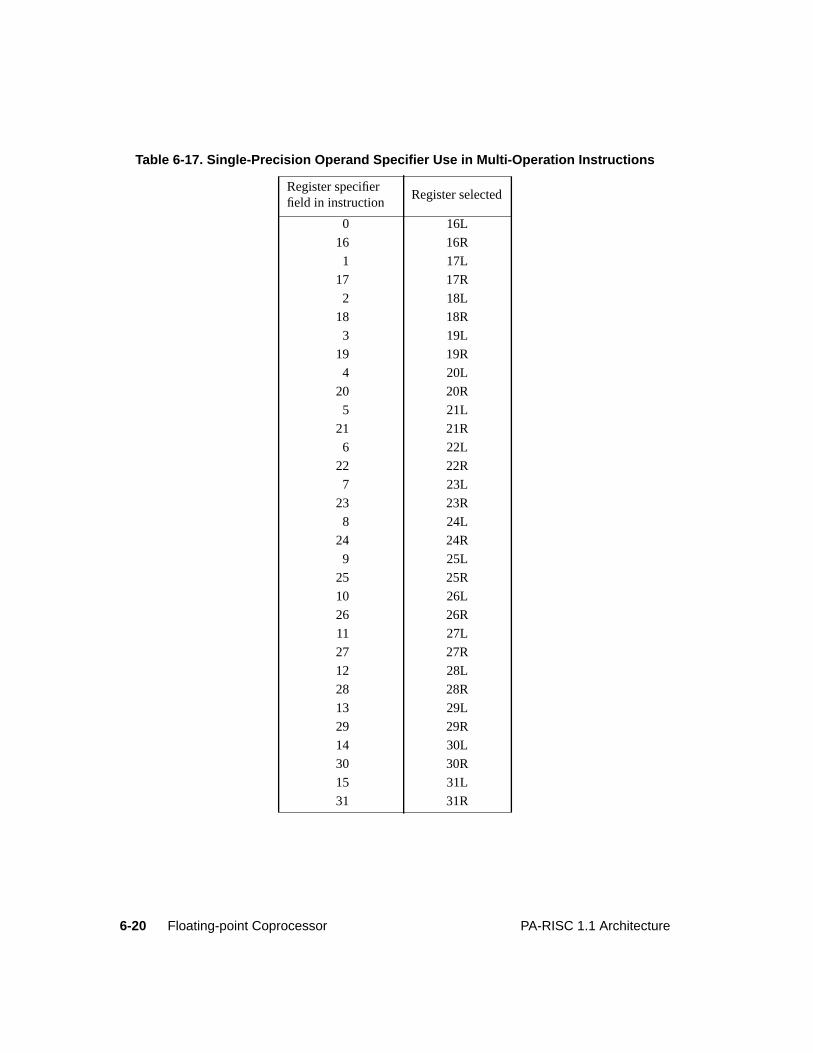
6-20 Floating-point Coprocessor PA-RISC 1.1 Architecture
Table 6-17. Single-Precision Operand Specifier Use in Multi-Operation Instructions
Register specifierfield in instruction
Register selected
0 16L
16 16R
1 17L
17 17R
2 18L
18 18R
3 19L
19 19R
4 20L
20 20R
5 21L
21 21R
6 22L
22 22R
7 23L
23 23R
8 24L
24 24R
9 25L
25 25R
10 26L
26 26R
11 27L
27 27R
12 28L
28 28R
13 29L
29 29R
14 30L
30 30R
15 31L
31 31R
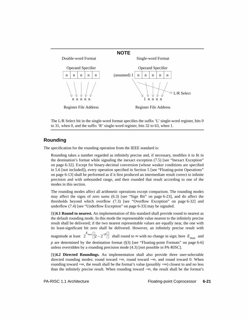
6-21PA-RISC 1.1 Architecture Floating-point Coprocessor
NOTE
The L/R Select bit in the single-word format specifies the suffix ‘L’ single-word register, bits 0to 31, when 0, and the suffix ‘R’ single-word register, bits 32 to 63, when 1.
Rounding
The specification for the rounding operation from the IEEE standard is:
Rounding takes a number regarded as infinitely precise and, if necessary, modifies it to fit inthe destination’s format while signaling the inexact exception (7.5) [see “Inexact Exception”on page 6-32]. Except for binary-decimal conversion (whose weaker conditions are specifiedin 5.6 [not included]), every operation specified in Section 5 [see “Floating-point Operations”on page 6-13] shall be performed as if it first produced an intermediate result correct to infiniteprecision and with unbounded range, and then rounded that result according to one of themodes in this section.
The rounding modes affect all arithmetic operations except comparison. The rounding modesmay affect the signs of zero sums (6.3) [see “Sign Bit” on page 6-23], and do affect thethresholds beyond which overflow (7.3) [see “Overflow Exception” on page 6-32] andunderflow (7.4) [see “Underflow Exception” on page 6-33] may be signaled.
[§]4.1 Round to nearest. An implementation of this standard shall provide round to nearest asthe default rounding mode. In this mode the representable value nearest to the infinitely preciseresult shall be delivered; if the two nearest representable values are equally near, the one withits least-significant bit zero shall be delivered. However, an infinitely precise result with
magnitude at least shall round to∞ with no change in sign; here and
p are determined by the destination format (§3) [see “Floating-point Formats” on page 6-6]unless overridden by a rounding precision mode (4.3) [not possible in PA-RISC].
[§]4.2 Directed Roundings. An implementation shall also provide three user-selectabledirected rounding modes: round toward +∞, round toward−∞, and round toward 0. Whenrounding toward +∞, the result shall be the format’s value (possibly +∞) closest to and no lessthan the infinitely precise result. When rounding toward−∞, the result shall be the format’s
Double-word Format
n n n n n
Operand Specifier
n n n n n
Register File Address
Single-word Format
n n n n n
Operand Specifier
1 n n n n
Register File Address
L/R Select
(assumed) 1
2Emax
2 2p–
–
Emax
6-22 Floating-point Coprocessor PA-RISC 1.1 Architecture
value (possibly−∞) closest to and no greater than the infinitely precise result. When roundingtoward 0, the result shall be the format’s value closest to and no greater in magnitude than theinfinitely precise result.
TheRM field in the Status Register determines the rounding mode.
While the above IEEE quote describes the process of rounding, an operation does not always return arounded result. The result of an operation may be affected if the operation causes an exception.
Infinity Arithmetic
From the standard:
[§]6.1 Infinity Arithmetic. Infinity arithmetic shall be construed as the limiting case of realarithmetic with operands of arbitrarily large magnitude, when such a limit exists. Infinitiesshall be interpreted in the affine sense, that is:
Arithmetic with an infinite operand is always exact and can only signal invalid and unimplementedexceptions. An infinite result is created from finite operands only by a non-trapping overflow exceptionor a non-trapping division-by-zero exception.
Operations With NaNs
From the standard:
[§]6.2 Operations with NaNs. Two different kinds of NaN, signaling and quiet, shall besupported in all operations. Signaling NaNs afford values for uninitialized variables andarithmetic-like enhancements (such as complex-affine infinities or extremely wide range) thatare not the subject of the standard. Quiet NaNs should, by means left to the implementor’sdiscretion, afford retrospective diagnostic information inherited from invalid or unavailabledata and results. Propagation of the diagnostic information requires that information containedin the NaNs be preserved through arithmetic operations and floating-point format conversions.
An operation causes an invalid exception when at least one operand is a signaling NaN and theoperation is any arithmetic operation except a convert to an integer format. Also, certain compareoperations cause an invalid exception if an operand is a quiet NaN. See “Comparison Conditions” onpage 6-17 for more detail.
Converting either a quiet or a signaling NaN to an integer format causes an unimplemented exception.
A NaN is created in two ways. Any operation that causes a non-trapping invalid exception returns aquiet NaN. Otherwise, an operation returns a quiet NaN when at least one of its operands is a quietNaN, and the operation is any arithmetic operation except a conversion to an integer format.
An operation converts a signaling NaN to a quiet NaN when the operation causes a non-trapping invalidexception and one of its operands is a signaling NaN. If both operands are signaling NaNs, the operationconverts the contents of the first operand (ther1 register).
An operation which converts a signaling NaN to a quiet NaN sets the first bit of the fraction ( ) to 0. Ifthe remaining bits in the fraction are all zeros ( ), the operation must set the second bit in
∞– every finite number( ) +∞< <
b1b2…bp 1– 0=
6-23PA-RISC 1.1 Architecture Floating-point Coprocessor
the fraction to 1. Otherwise, if the remainder of the fraction is not 0, an implementation has the optionof setting the second bit in the fraction to 1, or leaving it unchanged. Only the first and second bits in thefraction may change when creating a quiet NaN from a signaling NaN. The remaining fraction bits arecopied from the signaling NaN.
When one of its operands is a quiet NaN, but neither operand is a signaling NaN, an operation copiesthe quiet NaN to the destination. If both operands are quiet NaNs, ther1 register is copied to thedestination.
The creation of a quiet NaN when neither input is a NaN sets the second fraction bit ( ) to 1 and setseach of the remaining fraction bits to 0.
A conversion operation which does not trap, and which converts a NaN to a smaller floating-pointformat, preserves the most-significant portion of the fraction while returning a quiet NaN. But if themost-significant portion of the fraction is all zeros, the second bit of the fraction must be set to 1 toprevent the number from becoming an infinity. A conversion which does not trap, and which converts aNaN to a larger floating-point format, augments the fraction with zeros to the right of the smallerfraction while returning a quiet NaN.
Load and store instructions, as well as theFLOATING-POINT COPY andFLOATING-POINT ABSOLUTEVALUE instructions, are not arithmetic and do not signal an invalid operation exception.
Sign Bit
From the standard:
[§]6.3 The sign bit. This standard does not interpret the sign of a NaN. Otherwise the sign ofa product or quotient is the exclusive OR of the operands’ signs; and the sign of the sum, or ofa difference regarded as a sum , differs from at most one of the addends’ signs.These rules shall apply even when operands or results are zero or infinite.
When the sum of two operands with opposite signs (or the difference of two operands with likesigns) is exactly zero, the sign of that sum (or difference) shall be "+" in all rounding modesexcept round toward−∞, in which mode the sign shall be "−". However,retains the same sign asx even whenx is zero.
Except that shall be "−0", every valid square root shall have positive sign.
Exception RegistersThe exception registers contain information on floating-point operations that have completed executionand have caused a delayed trapping exception. All the registers must be present and storage provided forloads and stores even if an implementation never uses a particular register to record exception state.
The exception registers are accessed with double-word load and store instructions. Single-word loadsand stores of registers 0R, 1L, 1R, 2L, 2R, 3L, and 3R are undefined. Specifying an exception registeras a source or destination of a non-load/store operation is undefined.
For single-operation instructions, an exception register contains a modified copy of an exceptinginstruction that traps. The coprocessor replaces the field that normally contains the instruction opcode
b2
x y– x y–( )+
x x+ x x–( )–=
0–
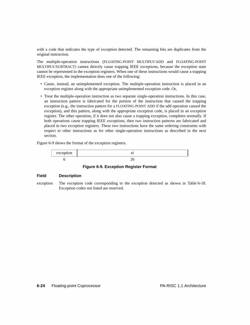
6-24 Floating-point Coprocessor PA-RISC 1.1 Architecture
with a code that indicates the type of exception detected. The remaining bits are duplicates from theoriginal instruction.
The multiple-operation instructions (FLOATING-POINT MULTIPLY/ADD and FLOATING-POINTMULTIPLY/SUBTRACT) cannot directly cause trapping IEEE exceptions, because the exception statecannot be represented in the exception registers. When one of these instructions would cause a trappingIEEE exception, the implementation does one of the following:
• Cause, instead, an unimplemented exception. The multiple-operation instruction is placed in anexception register along with the appropriate unimplemented exception code. Or,
• Treat the multiple-operation instruction as two separate single-operation instructions. In this case,an instruction pattern is fabricated for the portion of the instruction that caused the trappingexception (e.g., the instruction pattern for aFLOATING-POINT ADD if the add operation caused theexception), and this pattern, along with the appropriate exception code, is placed in an exceptionregister. The other operation, if it does not also cause a trapping exception, completes normally. Ifboth operations cause trapping IEEE exceptions, then two instruction patterns are fabricated andplaced in two exception registers. These two instructions have the same ordering constraints withrespect to other instructions as for other single-operation instructions as described in the nextsection.
Figure 6-9 shows the format of the exception registers.
Field Description
exception The exception code corresponding to the exception detected as shown in Table 6-18.Exception codes not listed are reserved.
exception ei
6 26
Figure 6-9. Exception Register Format

6-25PA-RISC 1.1 Architecture Floating-point Coprocessor
The two bits labeled ‘pp’ in the exception code contain information regarding theparameters for the underflow exceptions. See “Underflow Exception” on page 6-33 for adetailed description of this field.
ei All bits other than the major opcode, copied from the excepting instruction. This field isundefined if the exception code is set to ‘no exception’.
Exception Register OperationWhen all pending instructions are forced to complete, all operations which complete with a trappingexception are placed in the exception registers together with their corresponding exception codes. Inorder to complete an operation, the coprocessor may place the operation in an exception register andmark it with an unimplemented exception.
The coprocessor places the excepting instruction that first entered the IA queues in any of ExceptionRegisters 1 through 7. Other instructions which complete with a trap are placed in any of the otheravailable Exception Registers (those which are not already occupied by excepting instructions).Excepting instructions may be placed in the Exception Registers 1 through 7 in any order as long as thedata dependencies are preserved (the order need not be the order in which they were fetched). If aninstruction completes without a trapping exception, no record of that instruction appears in theexception registers. The exception queue need not be packed.
Once software has processed the exception registers, it must clear the exception registers by settingthem all to zeros before non-load/store instructions can be executed.
If the T-bit equals 0 and any exception register has an exception field not equal to "no exception",execution of any non-load/store floating-point instruction is an undefined operation.
Table 6-18. Exception Codes
Exception code Opcode Description
000000 0C/0E No exception
100000 0C/0E Invalid operation
010000 0C/0E Division-by-zero
001000 0C/0E Overflow
pp0100 0C/0E Underflow
000010 0C/0E Inexact
000001 0C/0E Unimplemented
001010 0C/0E Inexact & Overflow
pp0110 0C/0E Inexact & Underflow
001001 0C Unimplemented
001011 0E Unimplemented
000011 06 Unimplemented
100011 26 Unimplemented
6-26 Floating-point Coprocessor PA-RISC 1.1 Architecture
Interruptions and ExceptionsFloating-point instructions may cause interruptions in the processor, exceptions in the coprocessor, orboth. Coprocessor exceptions are divided into immediate trapping exceptions and delayed trappingexceptions. The only immediate trapping exception is the reserved-op exception. The delayed trappingexceptions consist of the unimplemented exception and the IEEE exceptions.
The IEEE exceptions are the following:
• invalid operation
• division-by-zero
• inexact
• overflow
• underflow
While the unimplemented and reserved-op exceptions must always trap, the IEEE exception traps maybe disabled.
Each IEEE exception has a corresponding enable bit in the Status Register. When an enable bit is 1, thecorresponding trap is enabled, and if the corresponding exception occurs, a delayed trap is taken.However, on the overflow and underflow exceptions, an implementation may choose to ignore theenable bit and always trap on the exception. In such implementations, the corresponding trap is alwaysenabled.
Immediate TrappingFloating-point instructions may cause three types of immediate trapping interruptions: memoryreference interruptions, the assist emulation trap, and the reserved-op exception. Immediate trappingexceptions and interruptions always cause a trap or fault when the front of the IA queues points to theinterrupting instruction. An interrupting instruction must not alter its operands.
As described in Chapter 4, “Flow Control and Interruptions”, when the processor detects a memoryreference problem, a memory reference fault or trap occurs. Only load and store instructions causememory reference interruptions. The memory reference interruptions associated with floating-pointinstructions are the following:
• Data TLB miss fault/Data page fault
• Data memory access rights trap
• Data memory protection ID trap
• Unaligned data reference trap
• Data memory break trap
• TLB dirty bit trap
• Page reference trap
• Data debug trap
6-27PA-RISC 1.1 Architecture Floating-point Coprocessor
As described in Chapter 5, “Instruction Set”, the Coprocessor Configuration Register (CCR) in theprocessor controls the assist emulation trap. Software may set this register to force an assist emulationtrap on every occurrence of a floating-point instruction. See “Coprocessor Instructions” on page 5-178for more information.
Finally, attempting an instruction with a reserved sub-opcode may cause an immediate assist exceptiontrap. See “Reserved-op Exception” on page 6-30 for details.
Delayed TrappingDelayed traps report an exception when the excepting instruction is a pending instruction but is not inthe IA queues. The following descriptions indicate when the processor and coprocessor may take adelayed trap and must take a delayed trap. Normally, a delayed trap forces the processor to take an assistexception trap. However, if the current instruction is a double-word store of Floating-point Register 0,all the floating-point registers are set normally as if a trap occurred, but the processor does not take theassist exception trap.
The coprocessor may signal a delayed trap when at least one of the following occurs:
• A pending instruction caused an unimplemented exception and the current instruction is a floating-point instruction, or
• A pending instruction caused an IEEE exception, the corresponding exception trap is enabled, andthe current instruction is a floating-point instruction.
A delayed trap must occur when at least one of the following conditions exist:
• The T-bit is 1 and the current instruction is any floating-point instruction.
• The exception queue is full.
• A pending instruction causes a trapping exception and the current instruction is a load or store ofFloating-point Register 0.
• The current instruction is a load or store of an exception register that will be set by a pendinginstruction.
• The current instruction is a load or store of the destination register of a pending, trappinginstruction or an operation which depends on a pending, trapping instruction.
• The current instruction is a load of the source register of a pending, trapping instruction or anoperation which depends on a pending, trapping instruction.
• The current instruction is aFLOATING-POINT TEST instruction and the previousFLOATING-POINTCOMPARE either is pending and caused a trapping exception or depends on a pending, trappinginstruction.
An instruction depends on a previous instruction whenever it must wait for the previous instruction tocomplete in order to ensure that the instructions appear sequentially executed to software. Instructiondependency is transitive. For example, if the exception queue is full, and every instruction in the queuedepends on the instruction immediately preceding it, then each instruction in the queue depends on allthe instructions preceding it.

6-28 Floating-point Coprocessor PA-RISC 1.1 Architecture
When a delayed trap occurs, the following happens:
1. The coprocessor completes all pending floating-point instructions.
2. The coprocessor sets the exception registers as described in “Exception Register Operation” onpage 6-25.
3. The coprocessor sets the Status Register T-bit to 1.
4. For each pending instruction that completes with a trapping IEEE exception, the correspondingexception flag may either be set to 1, or left unchanged, but cannot be set to 0.
5. If the current instruction is any floating-point instruction except a double-word store of Floating-point Register 0, the processor takes an assist exception trap. Otherwise, if the current instruction isa double-word store of Floating-point Register 0, the store completes, no trap occurs, the T-bit is setto 0 and execution proceeds normally.
Any pending instruction which depends on a pending, trapping instruction must complete with anunimplemented exception.
Table 6-19 specifies the status of the source and destination registers when an instruction causes adelayed trap. When the table indicates the original operand values are preserved, and if the destinationregister is not one of the source registers, the contents of the destination register are undefined.
As indicated in the table, trapping overflow exceptions and underflow exceptions return a rounded bias-adjusted result. A bias-adjusted result is obtained by dividing (in the case of overflow) or multiplying(in the case of underflow) the infinitely precise result by and then rounding. The bias adjustment,a,is 192 for single-word numbers, 1536 for double-word numbers, and 24576 for quad-word numbers.
Non-trapping ExceptionsIf an IEEE exception occurs, but the corresponding trap is disabled, then the coprocessor sets thecorresponding flag bit in the Status Register to 1. Table 6-20 lists the results returned by an operationwhich completes with a non-trapping exception.
Table 6-19. Delayed Trap Results
Exception type Trapped result
Invalid operation original operand values preserved
Division-by-zero original operand values preserved
Overflow rounded bias-adjusted result in destination
Underflow rounded bias-adjusted result in destination
Inexact rounded result in destination
Unimplemented original operand values preserved
2a
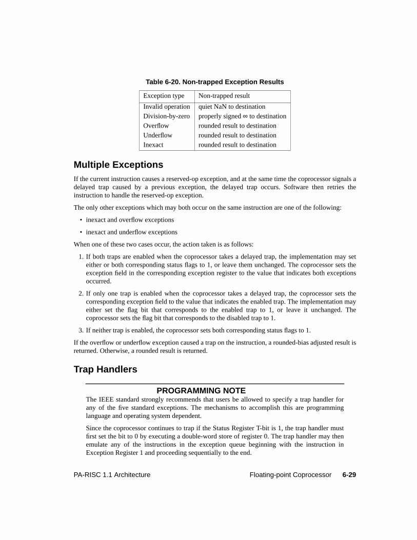
6-29PA-RISC 1.1 Architecture Floating-point Coprocessor
Multiple ExceptionsIf the current instruction causes a reserved-op exception, and at the same time the coprocessor signals adelayed trap caused by a previous exception, the delayed trap occurs. Software then retries theinstruction to handle the reserved-op exception.
The only other exceptions which may both occur on the same instruction are one of the following:
• inexact and overflow exceptions
• inexact and underflow exceptions
When one of these two cases occur, the action taken is as follows:
1. If both traps are enabled when the coprocessor takes a delayed trap, the implementation may seteither or both corresponding status flags to 1, or leave them unchanged. The coprocessor sets theexception field in the corresponding exception register to the value that indicates both exceptionsoccurred.
2. If only one trap is enabled when the coprocessor takes a delayed trap, the coprocessor sets thecorresponding exception field to the value that indicates the enabled trap. The implementation mayeither set the flag bit that corresponds to the enabled trap to 1, or leave it unchanged. Thecoprocessor sets the flag bit that corresponds to the disabled trap to 1.
3. If neither trap is enabled, the coprocessor sets both corresponding status flags to 1.
If the overflow or underflow exception caused a trap on the instruction, a rounded-bias adjusted result isreturned. Otherwise, a rounded result is returned.
Trap Handlers
PROGRAMMING NOTEThe IEEE standard strongly recommends that users be allowed to specify a trap handler forany of the five standard exceptions. The mechanisms to accomplish this are programminglanguage and operating system dependent.
Since the coprocessor continues to trap if the Status Register T-bit is 1, the trap handler mustfirst set the bit to 0 by executing a double-word store of register 0. The trap handler may thenemulate any of the instructions in the exception queue beginning with the instruction inException Register 1 and proceeding sequentially to the end.
Table 6-20. Non-trapped Exception Results
Exception type Non-trapped result
Invalid operation quiet NaN to destination
Division-by-zero properly signed∞ to destination
Overflow rounded result to destination
Underflow rounded result to destination
Inexact rounded result to destination
6-30 Floating-point Coprocessor PA-RISC 1.1 Architecture
The trap handler must clear all the exception registers. If the trap handler chooses not toemulate all the instructions, it must reset the T-bit to 1 before returning to the trapped process.
To emulate an instruction, the trap handler computes or specifies a substitute result to be placedin the destination register of the operation. The trap handler may determine what operation wasbeing performed and what exceptions occurred during the operation by examining thecorresponding exception register. On overflow, underflow, and inexact exceptions, the traphandler has access to the correctly rounded result by examining the destination register of theoperation. On unimplemented, invalid operation, and divide-by-zero exceptions, the traphandler has access to the operand values by examining the source registers of the instruction.
Reserved-op ExceptionWhen a non-load/store instruction has a reserved sub-opcode, an implementation signals either areserved-op exception or an unimplemented exception.
A reserved-op exception always forces the processor to take an immediate assist exception trap. It doesnot set the exception registers or the T-bit, and does not change any of the flag bits in the StatusRegister. The reserved-op exception cannot be disabled.
PROGRAMMING NOTETrapping is immediate for reserved-op exceptions. The trap handler must check for a StatusRegister T-bit equal to 0 to determine that the trap was caused by a reserved-op exception.When a reserved-op exception occurs, software interprets the contents of the IIR, nullifies theinstruction pointed to by the front of the IIA queues, and returns control to the trappingprocess.
Unimplemented ExceptionIf an implementation chooses not to execute an instruction, the instruction signals an unimplementedexception. An unimplemented exception always causes a delayed trap on a later floating-pointinstruction. It does not change the Status Register Flag bits and cannot be disabled. When a non-load/store floating-point operation references a reserved sub-opcode, an implementation signals either anunimplemented exception or a reserved-op exception.
An implementation may signal an unimplemented exception on any floating-point instruction except theFLOATING-POINT TEST instruction, theFLOATING-POINT IDENTIFY instruction, a load instruction, ora store instruction.
When a trap forces the coprocessor to complete all pending instructions, implementations may putuncompleted instructions in the exception registers and set the correspondingexception field to theappropriate unimplemented exception code.
A conversion to a floating-point format always causes an unimplemented exception when the resultoverflows, the result lies too far outside the range for the exponent to be bias-adjusted, and the overflowtrap is enabled. Table 6-21 shows the result values which produce an unimplemented exception;a is thebias-adjustment value for the destination format,p is the precision, andv is the source value.
6-31PA-RISC 1.1 Architecture Floating-point Coprocessor
Similarly, an unimplemented exception is always caused by a conversion to a floating-point format thatunderflows, lies too far outside the range for the exponent to be bias-adjusted, and the underflow trap isenabled. Table 6-22 shows the floating-point underflow results which cause an unimplementedexception;a is the bias-adjustment value for the destination format,p is the precision, andv is thesource value.
Finally, the unimplemented exception is always signaled when the operand of a conversion to an integerformat is a NaN or an∞, or when the result overflows. Table 6-23 shows the results which produce aninteger overflow. In the table, is the most positive integer representable by the destination format,
is the most negative, andv is the source value.
Table 6-21. Overflow Results Causing Unimplemented Exception
Rounding Mode Ranges
nearest
to 0
to +∞
to
Table 6-22. Underflow Results Causing Unimplemented Exception
Rounding Mode Range
nearest
to 0
to +∞
to
Table 6-23. Integer Results Causing Unimplemented Exception
Rounding Mode Ranges
nearest
to 0
to +∞
to
∞– v 2–Emax a+( )
2 2p–
–
≤< 2Emax a+( )
2 2p–
–
v +∞<≤
∞– v 2–Emax a 1+ +( )
≤< 2Emax a 1+ +( )
v +∞<≤
∞– v 2–Emax a 1+ +( )
≤< 2Emax a+( )
2 2p 1–( )–
–
v +∞< <
∞– ∞– v 2–Emax a+( )
2 2p 1–( )–
–
< < 2Emax a 1+ +( )
v +∞<≤
2–Emin a–( )
1 2p 1+( )–
–
v 2Emin a–( )
1 2p 1+( )–
–
< <
2–Emin a–( )
v 2Emin a–( )
< <
2–Emin a–( )
v 2Emin a–( )
1 2p–
–
≤<
∞– 2–Emin a–( )
1 2p–
–
v 2Emin a–( )
<≤
ImaxImin
v Imin 1 2⁄–< v Imax 1 2⁄+≥
v Imin 1–≤ v Imax 1+≥
v Imin 1–≤ v Imax>
∞– v Imin< v Imax 1+≥
6-32 Floating-point Coprocessor PA-RISC 1.1 Architecture
Invalid Operation ExceptionAn instruction signals the invalid operation exception if an operand is invalid for the operation to beperformed. When the exception occurs without a trap, the coprocessor delivers a quiet NaN to thedestination register. If the exception causes a trap, the coprocessor leaves the operands unchanged.
The invalid operations are:
1. Any arithmetic operation on a signaling NaN except for conversions to integer formats.
2. Magnitude subtraction of infinities like or ;
3. The multiplication of 0 and∞;
4. The division operations and ;
5. Square root if the operand is less than zero;
6. Comparison using conditions involving a "T" or conditions involving "<", ">", "true", or "false"without a "?", when the operands are unordered. See “Comparison Conditions” on page 6-17.
Division-by-zero ExceptionFrom the standard:
[§]7.2 Division by zero. If the divisor is zero and the dividend is a finite nonzero number, thenthe division by zero exception is signaled. The result, when no trap occurs, is a correctly signed∞ (6.3) [see “Sign Bit” on page 6-23].
When a trap occurs, the operands must be left unchanged.
Inexact ExceptionFrom the standard:
[§]7.5 Inexact. If the rounded result of an operation is not exact or if it overflows without anoverflow trap, then the inexact exception shall be signaled. The rounded or overflowed resultshall be delivered to the destination or, if an inexact trap occurs, to the trap handler [thedestination register in this architecture].
A conversion to a fixed-point format also signals the inexact exception when the result is not exact.
Overflow ExceptionTo determine overflow on an operation, the coprocessor uses the result that would have occurred had theresult been computed and rounded as if the destination’s exponent range were unbounded. On alloperations except converts, the coprocessor signals an overflow exception when the magnitude of thisresult exceeds the destination format’s largest finite number. The same is true of conversion operations,except that when this result is beyond the range of bias-adjusted numbers and the overflow trap isenabled, the instruction causes an unimplemented exception.
An instruction cannot cause an overflow exception when at least one operand is a NaN or infinity.
+∞( ) ∞–( )+ +∞( ) +∞( )–
0 0⁄ ∞ ∞⁄
6-33PA-RISC 1.1 Architecture Floating-point Coprocessor
Table 6-24 summarizes the result values that cause an overflow exception. In the table, is themaximum exponent value for the destination format,p is the precision of the format, andv is the valueof the exact result before rounding.
* When the overflow trap is enabled and the operation is a conversion to a floating-point format,this bound is limited to bias-adjusted numbers. See “Unimplemented Exception” on page 6-30.
When no trap occurs, the result of an overflow exception is one of the following:
1. Round to nearest carries all overflows to∞ with no change in sign.
2. Round toward 0 carries all overflows to the format’s largest finite number with no change in sign.
3. Round toward−∞ carries positive overflows to the format’s largest finite number, and carriesnegative overflows to−∞.
4. Round toward +∞ carries negative overflows to the format’s most negative finite number, andcarries positive overflows to +∞.
When an overflow exception causes a trap, the excepting operation returns a bias-adjusted number tothe destination register.
The overflow exception is not signaled for integer results. The coprocessor signals integer overflowswith an unimplemented exception.
Underflow ExceptionFrom the standard:
[§]7.4 Underflow. Two correlated events contribute to underflow. One is the creation of a tiny
nonzero result between which, because it is tiny, may cause some other exception latersuch as overflow upon division. The other is extraordinary loss of accuracy during theapproximation of such tiny numbers by denormalized numbers.
Tininess is detected on a nonzero result which lies strictly between , when the result is roundedas if the exponent range were unbounded. Note that rounding for detection of tininess and rounding todetermine a result are distinct. In certain cases, the coprocessor signals an underflow exception eventhough it returns a normalized result to the destination register.
Table 6-24. Results Causing Overflow Exception
Rounding Mode Ranges
nearest
to 0
to +∞
to
Emax
2Emax
2 2p–
–
v +∞*<≤ ∞–*
v 2Emax
2 2p–
–
–≤<
2Emax 1+( )
v +∞*<≤ ∞–*
v 2Emax 1+( )
–≤<
2Emax
2 2p 1–( )–
–
v +∞*< < ∞–*
v 2Emax 1+( )
–≤<
∞– 2Emax 1+( )
v +∞*<≤ ∞–*
v 2Emax
2 2p 1–( )–
–
–< <
2Emin±
2Emin±
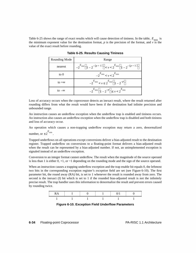
6-34 Floating-point Coprocessor PA-RISC 1.1 Architecture
Table 6-25 shows the range of exact results which will cause detection of tininess. In the table, isthe minimum exponent value for the destination format,p is the precision of the format, andv is thevalue of the exact result before rounding.
Loss of accuracy occurs when the coprocessor detects an inexact result, where the result returned afterrounding differs from what the result would have been if the destination had infinite precision andunbounded range.
An instruction causes an underflow exception when the underflow trap is enabled and tininess occurs.An instruction also causes an underflow exception when the underflow trap is disabled and both tininessand loss of accuracy occur.
An operation which causes a non-trapping underflow exception may return a zero, denormalized
number, or .
Trapped underflows on all operations except conversions deliver a bias-adjusted result to the destinationregister. Trapped underflow on conversions to a floating-point format delivers a bias-adjusted resultwhen the result can be represented by a bias-adjusted number. If not, an unimplemented exception issignaled instead of an underflow exception.
Conversion to an integer format cannot underflow. The result when the magnitude of the source operandis less than 1 is either 0, +1, or−1 depending on the rounding mode and the sign of the source operand.
When an instruction causes a trapping underflow exception and the trap enable bit equals 0, the leftmosttwo bits in the corresponding exception register’sexception field are set (see Figure 6-10). The firstparameter bit, the round away (RA) bit, is set to 1 whenever the result is rounded away from zero. Thesecond is the inexact (I) bit which is set to 1 if the rounded bias-adjusted result is not the infinitelyprecise result. The trap handler uses this information to denormalize the result and prevent errors causedby rounding twice.
Table 6-25. Results Causing Tininess
Rounding Mode Range
nearest
to 0
to +∞
to
RA I 0 1 0/1 0
1 1 1 1 1 1
Figure 6-10. Exception Field Underflow Parameters
Emin
2Emin
1 2p 1+( )–
–
– v 2Emin
1 2p 1+( )–
–
< <
2Emin
– v 2Emin< <
2Emin
– v 2Emin
1 2p–
–
≤<
∞– 2Emin
1 2p–
–
– v 2Emin<≤
2Emin±
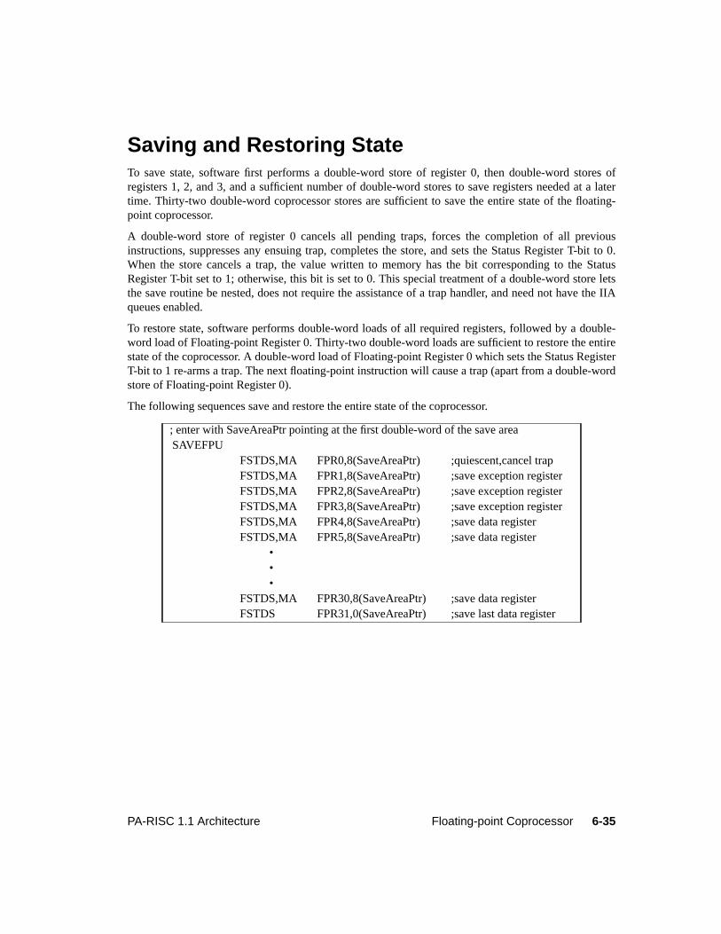
6-35PA-RISC 1.1 Architecture Floating-point Coprocessor
Saving and Restoring StateTo save state, software first performs a double-word store of register 0, then double-word stores ofregisters 1, 2, and 3, and a sufficient number of double-word stores to save registers needed at a latertime. Thirty-two double-word coprocessor stores are sufficient to save the entire state of the floating-point coprocessor.
A double-word store of register 0 cancels all pending traps, forces the completion of all previousinstructions, suppresses any ensuing trap, completes the store, and sets the Status Register T-bit to 0.When the store cancels a trap, the value written to memory has the bit corresponding to the StatusRegister T-bit set to 1; otherwise, this bit is set to 0. This special treatment of a double-word store letsthe save routine be nested, does not require the assistance of a trap handler, and need not have the IIAqueues enabled.
To restore state, software performs double-word loads of all required registers, followed by a double-word load of Floating-point Register 0. Thirty-two double-word loads are sufficient to restore the entirestate of the coprocessor. A double-word load of Floating-point Register 0 which sets the Status RegisterT-bit to 1 re-arms a trap. The next floating-point instruction will cause a trap (apart from a double-wordstore of Floating-point Register 0).
The following sequences save and restore the entire state of the coprocessor.
; enter with SaveAreaPtr pointing at the first double-word of the save areaSAVEFPU
FSTDS,MA FPR0,8(SaveAreaPtr) ;quiescent,cancel trapFSTDS,MA FPR1,8(SaveAreaPtr) ;save exception registerFSTDS,MA FPR2,8(SaveAreaPtr) ;save exception registerFSTDS,MA FPR3,8(SaveAreaPtr) ;save exception registerFSTDS,MA FPR4,8(SaveAreaPtr) ;save data registerFSTDS,MA FPR5,8(SaveAreaPtr) ;save data register
•••
FSTDS,MA FPR30,8(SaveAreaPtr) ;save data registerFSTDS FPR31,0(SaveAreaPtr) ;save last data register
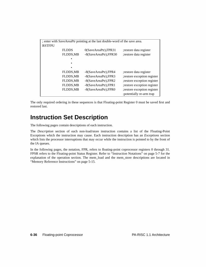
6-36 Floating-point Coprocessor PA-RISC 1.1 Architecture
The only required ordering in these sequences is that Floating-point Register 0 must be saved first andrestored last.
Instruction Set DescriptionThe following pages contain descriptions of each instruction.
The Description section of each non-load/store instruction contains a list of the Floating-PointExceptions which the instruction may cause. Each instruction description has anExceptions sectionwhich lists the processor interruptions that may occur while the instruction is pointed to by the front ofthe IA queues.
In the following pages, the notation, FPR, refers to floating-point coprocessor registers 0 through 31.FPSR refers to the Floating-point Status Register. Refer to “Instruction Notations” on page 5-7 for theexplanation of the operation section. The mem_load and the mem_store descriptions are located in“Memory Reference Instructions” on page 5-15.
; enter with SaveAreaPtr pointing at the last double-word of the save area.RSTFPU
FLDDS 0(SaveAreaPtr),FPR31 ;restore data registerFLDDS,MB -8(SaveAreaPtr),FPR30 ;restore data register
•••
FLDDS,MB -8(SaveAreaPtr),FPR4 ;restore data registerFLDDS,MB -8(SaveAreaPtr),FPR3 ;restore exception registerFLDDS,MB -8(SaveAreaPtr),FPR2 ;restore exception registerFLDDS,MB -8(SaveAreaPtr),FPR1 ;restore exception registerFLDDS,MB -8(SaveAreaPtr),FPR0 ;restore exception register
;potentially re-arm trap
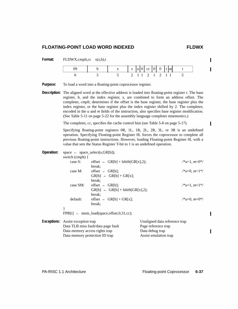
6-37PA-RISC 1.1 Architecture Floating-point Coprocessor
6Floating-point CoprocessorFLOATING-POINT LOAD WORD INDEXED FLDWX
Format: FLDWX,cmplt,cc x(s,b),t
Purpose: To load a word into a floating-point coprocessor register.
Description: The aligned word at the effective address is loaded into floating-point registert. The baseregister, b, and the index register,x, are combined to form an address offset. Thecompleter,cmplt, determines if the offset is the base register, the base register plus theindex register, or the base register plus the index register shifted by 2. The completer,encoded in theu andm fields of the instruction, also specifies base register modification.(See Table 5-11 on page 5-22 for the assembly language completer mnemonics.)
The completer,cc, specifies the cache control hint (see Table 5-8 on page 5-17).
Specifying floating-point registers 0R, 1L, 1R, 2L, 2R, 3L, or 3R is an undefinedoperation. Specifying Floating-point Register 0L forces the coprocessor to complete allprevious floating-point instructions. However, loading Floating-point Register 0L with avalue that sets the Status Register T-bit to 1 is an undefined operation.
Operation: space← space_select(s,GR[b]);switch (cmplt) {
case S: offset← GR[b] + lshift(GR[x],2); /*u=1, m=0*/break;
case M: offset← GR[b]; /*u=0, m=1*/GR[b] ← GR[b] + GR[x];break;
case SM: offset← GR[b]; /*u=1, m=1*/GR[b] ← GR[b] + lshift(GR[x],2);break;
default: offset← GR[b] + GR[x]; /*u=0, m=0*/break;
}FPR[t] ← mem_load(space,offset,0,31,cc);
Exceptions: Assist exception trap Unaligned data reference trapData TLB miss fault/data page fault Page reference trapData memory access rights trap Data debug trapData memory protection ID trap Assist emulation trap
09 b x s u 0 cc 0 0 t m t
6 5 5 2 1 1 2 1 2 1 1 5
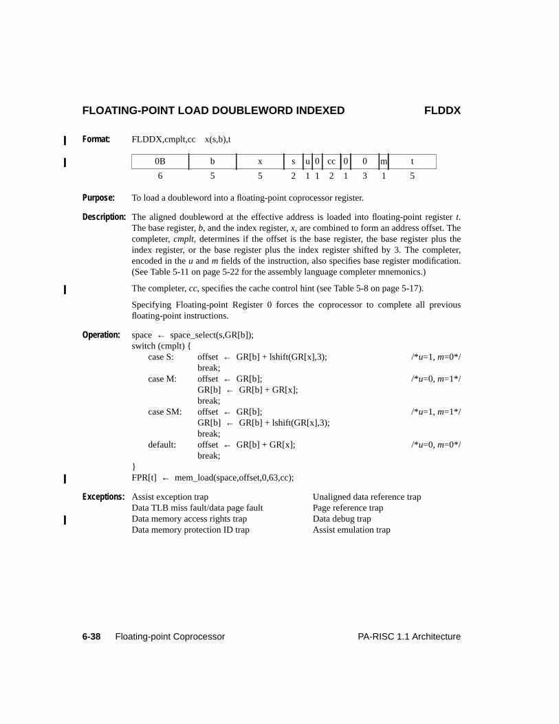
6-38 Floating-point Coprocessor PA-RISC 1.1 Architecture
FLOATING-POINT LOAD DOUBLEWORD INDEXED FLDDX
Format: FLDDX,cmplt,cc x(s,b),t
Purpose: To load a doubleword into a floating-point coprocessor register.
Description: The aligned doubleword at the effective address is loaded into floating-point registert.The base register,b, and the index register,x, are combined to form an address offset. Thecompleter,cmplt, determines if the offset is the base register, the base register plus theindex register, or the base register plus the index register shifted by 3. The completer,encoded in theu andm fields of the instruction, also specifies base register modification.(See Table 5-11 on page 5-22 for the assembly language completer mnemonics.)
The completer,cc, specifies the cache control hint (see Table 5-8 on page 5-17).
Specifying Floating-point Register 0 forces the coprocessor to complete all previousfloating-point instructions.
Operation: space← space_select(s,GR[b]);switch (cmplt) {
case S: offset← GR[b] + lshift(GR[x],3); /*u=1, m=0*/break;
case M: offset← GR[b]; /*u=0, m=1*/GR[b] ← GR[b] + GR[x];break;
case SM: offset← GR[b]; /*u=1, m=1*/GR[b] ← GR[b] + lshift(GR[x],3);break;
default: offset← GR[b] + GR[x]; /*u=0, m=0*/break;
}FPR[t] ← mem_load(space,offset,0,63,cc);
Exceptions: Assist exception trap Unaligned data reference trapData TLB miss fault/data page fault Page reference trapData memory access rights trap Data debug trapData memory protection ID trap Assist emulation trap
0B b x s u 0 cc 0 0 m t
6 5 5 2 1 1 2 1 3 1 5
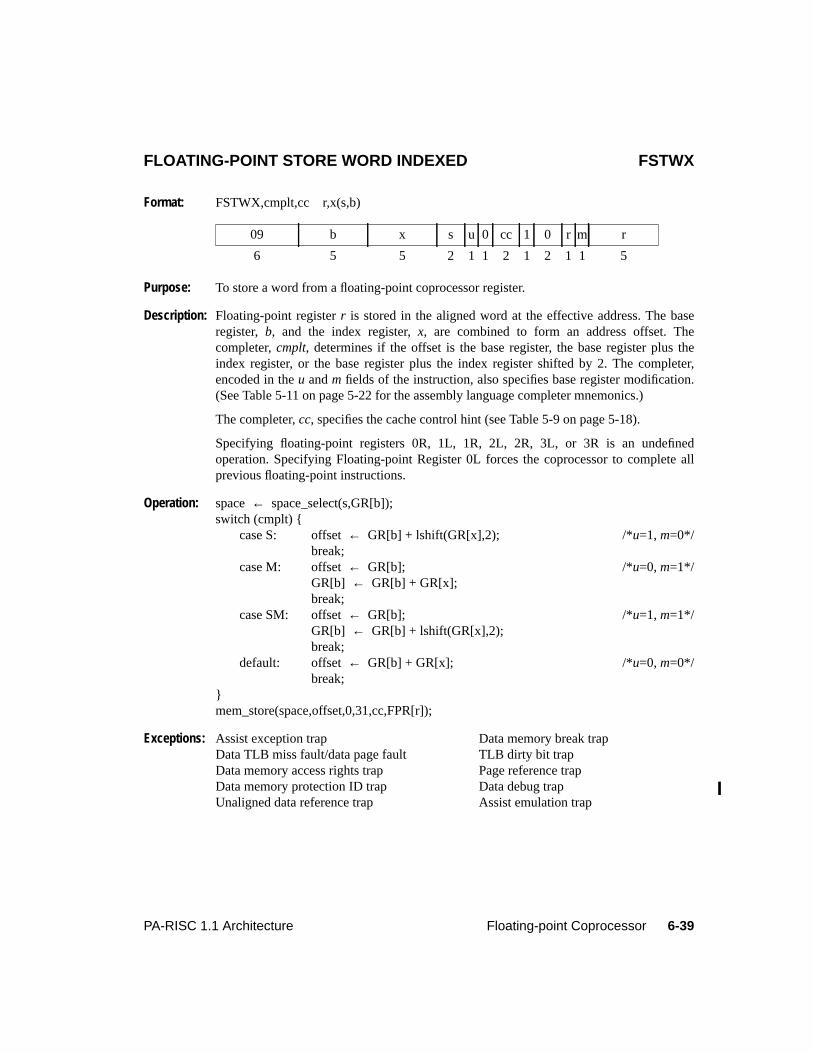
6-39PA-RISC 1.1 Architecture Floating-point Coprocessor
FLOATING-POINT STORE WORD INDEXED FSTWX
Format: FSTWX,cmplt,cc r,x(s,b)
Purpose: To store a word from a floating-point coprocessor register.
Description: Floating-point registerr is stored in the aligned word at the effective address. The baseregister, b, and the index register,x, are combined to form an address offset. Thecompleter,cmplt, determines if the offset is the base register, the base register plus theindex register, or the base register plus the index register shifted by 2. The completer,encoded in theu andm fields of the instruction, also specifies base register modification.(See Table 5-11 on page 5-22 for the assembly language completer mnemonics.)
The completer,cc, specifies the cache control hint (see Table 5-9 on page 5-18).
Specifying floating-point registers 0R, 1L, 1R, 2L, 2R, 3L, or 3R is an undefinedoperation. Specifying Floating-point Register 0L forces the coprocessor to complete allprevious floating-point instructions.
Operation: space← space_select(s,GR[b]);switch (cmplt) {
case S: offset← GR[b] + lshift(GR[x],2); /*u=1, m=0*/break;
case M: offset← GR[b]; /*u=0, m=1*/GR[b] ← GR[b] + GR[x];break;
case SM: offset← GR[b]; /*u=1, m=1*/GR[b] ← GR[b] + lshift(GR[x],2);break;
default: offset← GR[b] + GR[x]; /*u=0, m=0*/break;
}mem_store(space,offset,0,31,cc,FPR[r]);
Exceptions: Assist exception trap Data memory break trapData TLB miss fault/data page fault TLB dirty bit trapData memory access rights trap Page reference trapData memory protection ID trap Data debug trapUnaligned data reference trap Assist emulation trap
09 b x s u 0 cc 1 0 r m r
6 5 5 2 1 1 2 1 2 1 1 5
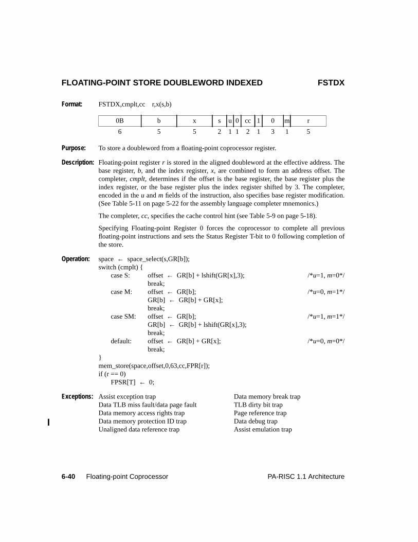
6-40 Floating-point Coprocessor PA-RISC 1.1 Architecture
FLOATING-POINT STORE DOUBLEWORD INDEXED FSTDX
Format: FSTDX,cmplt,cc r,x(s,b)
Purpose: To store a doubleword from a floating-point coprocessor register.
Description: Floating-point registerr is stored in the aligned doubleword at the effective address. Thebase register,b, and the index register,x, are combined to form an address offset. Thecompleter,cmplt, determines if the offset is the base register, the base register plus theindex register, or the base register plus the index register shifted by 3. The completer,encoded in theu andm fields of the instruction, also specifies base register modification.(See Table 5-11 on page 5-22 for the assembly language completer mnemonics.)
The completer,cc, specifies the cache control hint (see Table 5-9 on page 5-18).
Specifying Floating-point Register 0 forces the coprocessor to complete all previousfloating-point instructions and sets the Status Register T-bit to 0 following completion ofthe store.
Operation: space← space_select(s,GR[b]);switch (cmplt) {
case S: offset← GR[b] + lshift(GR[x],3); /*u=1, m=0*/break;
case M: offset← GR[b]; /*u=0, m=1*/GR[b] ← GR[b] + GR[x];break;
case SM: offset← GR[b]; /*u=1, m=1*/GR[b] ← GR[b] + lshift(GR[x],3);break;
default: offset← GR[b] + GR[x]; /*u=0, m=0*/break;
}mem_store(space,offset,0,63,cc,FPR[r]);if (r == 0)
FPSR[T] ← 0;
Exceptions: Assist exception trap Data memory break trapData TLB miss fault/data page fault TLB dirty bit trapData memory access rights trap Page reference trapData memory protection ID trap Data debug trapUnaligned data reference trap Assist emulation trap
0B b x s u 0 cc 1 0 m r
6 5 5 2 1 1 2 1 3 1 5
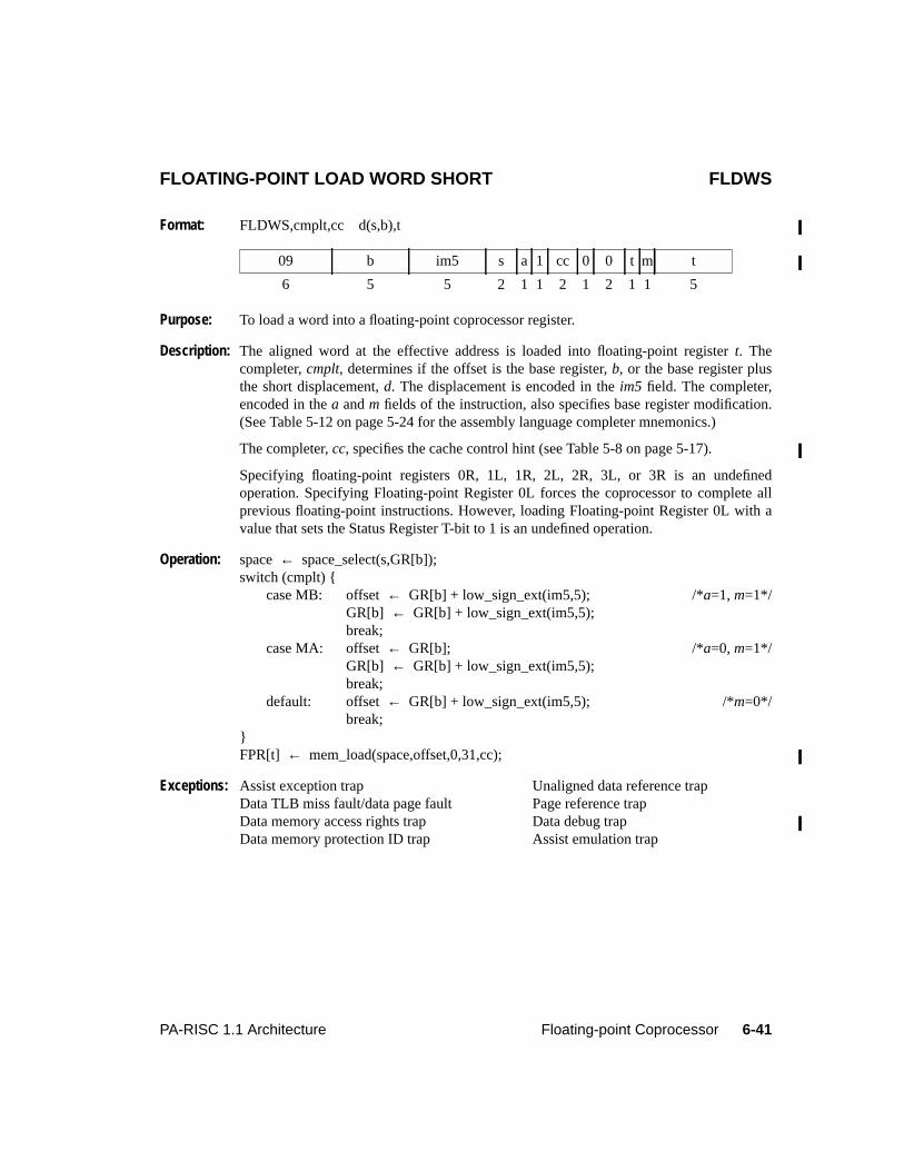
6-41PA-RISC 1.1 Architecture Floating-point Coprocessor
FLOATING-POINT LOAD WORD SHORT FLDWS
Format: FLDWS,cmplt,cc d(s,b),t
Purpose: To load a word into a floating-point coprocessor register.
Description: The aligned word at the effective address is loaded into floating-point registert. Thecompleter,cmplt, determines if the offset is the base register,b, or the base register plusthe short displacement,d. The displacement is encoded in theim5 field. The completer,encoded in thea andm fields of the instruction, also specifies base register modification.(See Table 5-12 on page 5-24 for the assembly language completer mnemonics.)
The completer,cc, specifies the cache control hint (see Table 5-8 on page 5-17).
Specifying floating-point registers 0R, 1L, 1R, 2L, 2R, 3L, or 3R is an undefinedoperation. Specifying Floating-point Register 0L forces the coprocessor to complete allprevious floating-point instructions. However, loading Floating-point Register 0L with avalue that sets the Status Register T-bit to 1 is an undefined operation.
Operation: space← space_select(s,GR[b]);switch (cmplt) {
case MB: offset← GR[b] + low_sign_ext(im5,5); /*a=1, m=1*/GR[b] ← GR[b] + low_sign_ext(im5,5);break;
case MA: offset← GR[b]; /*a=0, m=1*/GR[b] ← GR[b] + low_sign_ext(im5,5);break;
default: offset← GR[b] + low_sign_ext(im5,5); /*m=0*/break;
}FPR[t] ← mem_load(space,offset,0,31,cc);
Exceptions: Assist exception trap Unaligned data reference trapData TLB miss fault/data page fault Page reference trapData memory access rights trap Data debug trapData memory protection ID trap Assist emulation trap
09 b im5 s a 1 cc 0 0 t m t
6 5 5 2 1 1 2 1 2 1 1 5
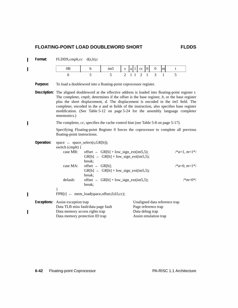
6-42 Floating-point Coprocessor PA-RISC 1.1 Architecture
FLOATING-POINT LOAD DOUBLEWORD SHORT FLDDS
Format: FLDDS,cmplt,cc d(s,b),t
Purpose: To load a doubleword into a floating-point coprocessor register.
Description: The aligned doubleword at the effective address is loaded into floating-point registert.The completer,cmplt, determines if the offset is the base register,b, or the base registerplus the short displacement,d. The displacement is encoded in theim5 field. Thecompleter, encoded in thea andm fields of the instruction, also specifies base registermodification. (See Table 5-12 on page 5-24 for the assembly language completermnemonics.)
The completer,cc, specifies the cache control hint (see Table 5-8 on page 5-17).
Specifying Floating-point Register 0 forces the coprocessor to complete all previousfloating-point instructions.
Operation: space← space_select(s,GR[b]);switch (cmplt) {
case MB: offset← GR[b] + low_sign_ext(im5,5); /*a=1, m=1*/GR[b] ← GR[b] + low_sign_ext(im5,5);break;
case MA: offset← GR[b]; /*a=0, m=1*/GR[b] ← GR[b] + low_sign_ext(im5,5);break;
default: offset← GR[b] + low_sign_ext(im5,5); /*m=0*/break;
}FPR[t] ← mem_load(space,offset,0,63,cc);
Exceptions: Assist exception trap Unaligned data reference trapData TLB miss fault/data page fault Page reference trapData memory access rights trap Data debug trapData memory protection ID trap Assist emulation trap
0B b im5 s a 1 cc 0 0 m t
6 5 5 2 1 1 2 1 3 1 5
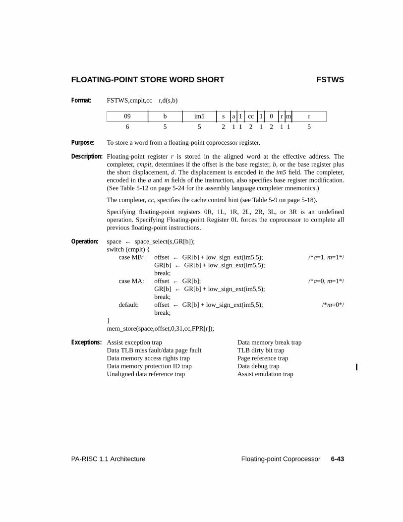
6-43PA-RISC 1.1 Architecture Floating-point Coprocessor
FLOATING-POINT STORE WORD SHORT FSTWS
Format: FSTWS,cmplt,cc r,d(s,b)
Purpose: To store a word from a floating-point coprocessor register.
Description: Floating-point registerr is stored in the aligned word at the effective address. Thecompleter,cmplt, determines if the offset is the base register,b, or the base register plusthe short displacement,d. The displacement is encoded in theim5 field. The completer,encoded in thea andm fields of the instruction, also specifies base register modification.(See Table 5-12 on page 5-24 for the assembly language completer mnemonics.)
The completer,cc, specifies the cache control hint (see Table 5-9 on page 5-18).
Specifying floating-point registers 0R, 1L, 1R, 2L, 2R, 3L, or 3R is an undefinedoperation. Specifying Floating-point Register 0L forces the coprocessor to complete allprevious floating-point instructions.
Operation: space← space_select(s,GR[b]);switch (cmplt) {
case MB: offset← GR[b] + low_sign_ext(im5,5); /*a=1, m=1*/GR[b] ← GR[b] + low_sign_ext(im5,5);break;
case MA: offset← GR[b]; /*a=0, m=1*/GR[b] ← GR[b] + low_sign_ext(im5,5);break;
default: offset← GR[b] + low_sign_ext(im5,5); /*m=0*/break;
}mem_store(space,offset,0,31,cc,FPR[r]);
Exceptions: Assist exception trap Data memory break trapData TLB miss fault/data page fault TLB dirty bit trapData memory access rights trap Page reference trapData memory protection ID trap Data debug trapUnaligned data reference trap Assist emulation trap
09 b im5 s a 1 cc 1 0 r m r
6 5 5 2 1 1 2 1 2 1 1 5
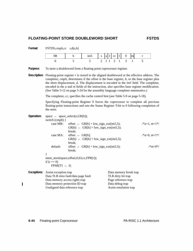
6-44 Floating-point Coprocessor PA-RISC 1.1 Architecture
FLOATING-POINT STORE DOUBLEWORD SHORT FSTDS
Format: FSTDS,cmplt,cc r,d(s,b)
Purpose: To store a doubleword from a floating-point coprocessor register.
Description: Floating-point registerr is stored in the aligned doubleword at the effective address. Thecompleter,cmplt, determines if the offset is the base register,b, or the base register plusthe short displacement,d. The displacement is encoded in theim5 field. The completer,encoded in thea andm fields of the instruction, also specifies base register modification.(See Table 5-12 on page 5-24 for the assembly language completer mnemonics.)
The completer,cc, specifies the cache control hint (see Table 5-9 on page 5-18).
Specifying Floating-point Register 0 forces the coprocessor to complete all previousfloating-point instructions and sets the Status Register T-bit to 0 following completion ofthe store.
Operation: space← space_select(s,GR[b]);switch (cmplt) {
case MB: offset← GR[b] + low_sign_ext(im5,5); /*a=1, m=1*/GR[b] ← GR[b] + low_sign_ext(im5,5);break;
case MA: offset← GR[b]; /*a=0, m=1*/GR[b] ← GR[b] + low_sign_ext(im5,5);break;
default: offset← GR[b] + low_sign_ext(im5,5); /*m=0*/break;
}mem_store(space,offset,0,63,cc,FPR[r]);if (r == 0)
FPSR[T] ← 0;
Exceptions: Assist exception trap Data memory break trapData TLB miss fault/data page fault TLB dirty bit trapData memory access rights trap Page reference trapData memory protection ID trap Data debug trapUnaligned data reference trap Assist emulation trap
0B b im5 s a 1 cc 1 0 m r
6 5 5 2 1 1 2 1 3 1 5
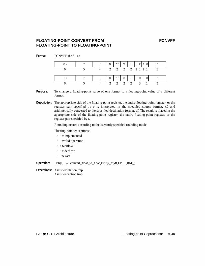
6-45PA-RISC 1.1 Architecture Floating-point Coprocessor
6Floating-point CoprocessorFLOATING-POINT CONVERT FROM FCNVFFFLOATING-POINT TO FLOATING-POINT
Format: FCNVFF,sf,df r,t
Purpose: To change a floating-point value of one format to a floating-point value of a differentformat.
Description: The appropriate side of the floating-point register, the entire floating-point register, or theregister pair specified byr is interpreted in the specified source format,sf, andarithmetically converted to the specified destination format,df. The result is placed in theappropriate side of the floating-point register, the entire floating-point register, or theregister pair specified byt.
Rounding occurs according to the currently specified rounding mode.
Floating-point exceptions:
• Unimplemented
• Invalid operation
• Overflow
• Underflow
• Inexact
Operation: FPR[t] ← convert_float_to_float(FPR[r],sf,df,FPSR[RM]);
Exceptions: Assist emulation trapAssist exception trap
0E r 0 0 df sf 1 0 r t 0 t
6 5 4 2 2 2 2 1 1 1 1 5
0C r 0 0 df sf 1 0 0 t
6 5 4 2 2 2 2 3 1 5
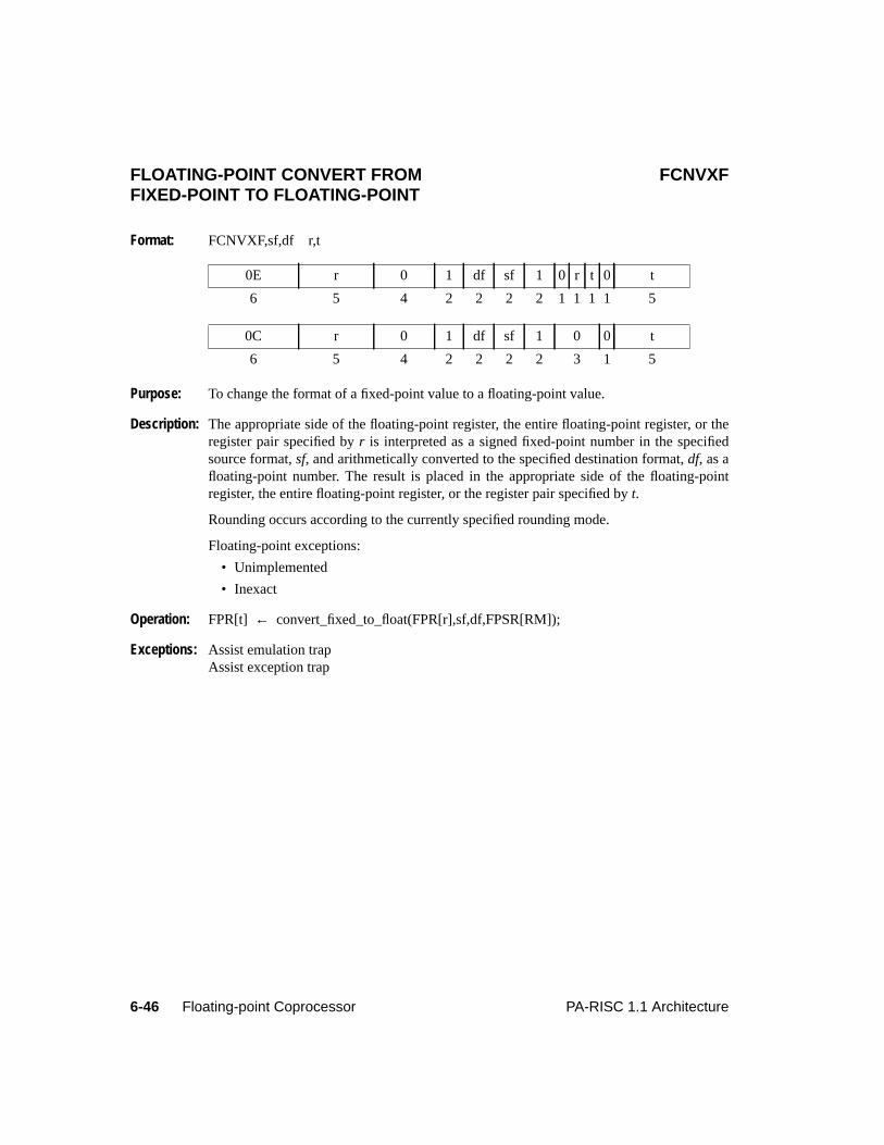
6-46 Floating-point Coprocessor PA-RISC 1.1 Architecture
FLOATING-POINT CONVERT FROM FCNVXFFIXED-POINT TO FLOATING-POINT
Format: FCNVXF,sf,df r,t
Purpose: To change the format of a fixed-point value to a floating-point value.
Description: The appropriate side of the floating-point register, the entire floating-point register, or theregister pair specified byr is interpreted as a signed fixed-point number in the specifiedsource format,sf, and arithmetically converted to the specified destination format,df, as afloating-point number. The result is placed in the appropriate side of the floating-pointregister, the entire floating-point register, or the register pair specified byt.
Rounding occurs according to the currently specified rounding mode.
Floating-point exceptions:
• Unimplemented
• Inexact
Operation: FPR[t] ← convert_fixed_to_float(FPR[r],sf,df,FPSR[RM]);
Exceptions: Assist emulation trapAssist exception trap
0E r 0 1 df sf 1 0 r t 0 t
6 5 4 2 2 2 2 1 1 1 1 5
0C r 0 1 df sf 1 0 0 t
6 5 4 2 2 2 2 3 1 5
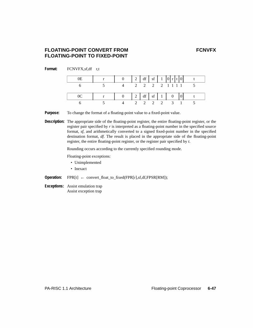
6-47PA-RISC 1.1 Architecture Floating-point Coprocessor
FLOATING-POINT CONVERT FROM FCNVFXFLOATING-POINT TO FIXED-POINT
Format: FCNVFX,sf,df r,t
Purpose: To change the format of a floating-point value to a fixed-point value.
Description: The appropriate side of the floating-point register, the entire floating-point register, or theregister pair specified byr is interpreted as a floating-point number in the specified sourceformat, sf, and arithmetically converted to a signed fixed-point number in the specifieddestination format,df. The result is placed in the appropriate side of the floating-pointregister, the entire floating-point register, or the register pair specified byt.
Rounding occurs according to the currently specified rounding mode.
Floating-point exceptions:
• Unimplemented
• Inexact
Operation: FPR[t] ← convert_float_to_fixed(FPR[r],sf,df,FPSR[RM]);
Exceptions: Assist emulation trapAssist exception trap
0E r 0 2 df sf 1 0 r t 0 t
6 5 4 2 2 2 2 1 1 1 1 5
0C r 0 2 df sf 1 0 0 t
6 5 4 2 2 2 2 3 1 5
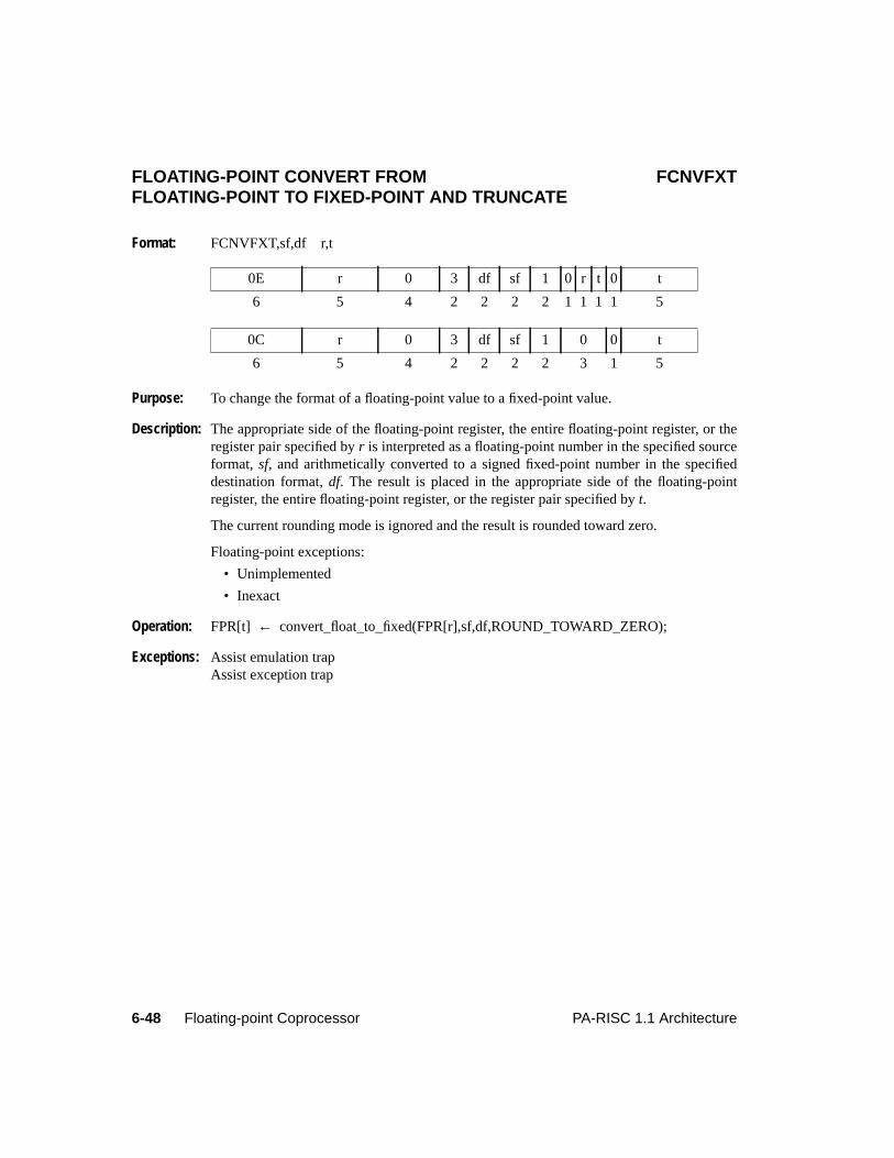
6-48 Floating-point Coprocessor PA-RISC 1.1 Architecture
FLOATING-POINT CONVERT FROM FCNVFXTFLOATING-POINT TO FIXED-POINT AND TRUNCATE
Format: FCNVFXT,sf,df r,t
Purpose: To change the format of a floating-point value to a fixed-point value.
Description: The appropriate side of the floating-point register, the entire floating-point register, or theregister pair specified byr is interpreted as a floating-point number in the specified sourceformat, sf, and arithmetically converted to a signed fixed-point number in the specifieddestination format,df. The result is placed in the appropriate side of the floating-pointregister, the entire floating-point register, or the register pair specified byt.
The current rounding mode is ignored and the result is rounded toward zero.
Floating-point exceptions:
• Unimplemented
• Inexact
Operation: FPR[t] ← convert_float_to_fixed(FPR[r],sf,df,ROUND_TOWARD_ZERO);
Exceptions: Assist emulation trapAssist exception trap
0E r 0 3 df sf 1 0 r t 0 t
6 5 4 2 2 2 2 1 1 1 1 5
0C r 0 3 df sf 1 0 0 t
6 5 4 2 2 2 2 3 1 5
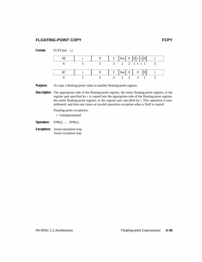
6-49PA-RISC 1.1 Architecture Floating-point Coprocessor
6Floating-point CoprocessorFLOATING-POINT COPY FCPY
Format: FCPY,fmt r,t
Purpose: To copy a floating-point value to another floating-point register.
Description: The appropriate side of the floating-point register, the entire floating-point register, or theregister pair specified byr is copied into the appropriate side of the floating-point register,the entire floating-point register, or the register pair specified byt. This operation is non-arithmetic and does not cause an invalid operation exception when a NaN is copied.
Floating-point exceptions:
• Unimplemented
Operation: FPR[t] ← FPR[r];
Exceptions: Assist emulation trapAssist exception trap
0E r 0 2 fmt 0 0 r t 0 t
6 5 5 3 2 2 1 1 1 1 5
0C r 0 2 fmt 0 0 0 t
6 5 5 3 2 2 3 1 5
6-50 Floating-point Coprocessor PA-RISC 1.1 Architecture
FLOATING-POINT ABSOLUTE VALUE FABS
Format: FABS,fmt r,t
Purpose: To perform a floating-point absolute value.
Description: The appropriate side of the floating-point register, the entire floating-point register, or theregister pair specified byr is copied to the appropriate side of the floating-point register,the entire floating-point register, or the register pair specified byt with the sign bit set to 0.This instruction is non-arithmetic and does not cause an invalid operation exception whenthe sign of a NaN is set to 0.
Floating-point exceptions:
• Unimplemented
Operation: FPR[t]{all_bits_except_sign}← FPR[r]{all_bits_except_sign};FPR[t]{sign_bit} ← 0;
Exceptions: Assist emulation trapAssist exception trap
0E r 0 3 fmt 0 0 r t 0 t
6 5 5 3 2 2 1 1 1 1 5
0C r 0 3 fmt 0 0 0 t
6 5 5 3 2 2 3 1 5
6-51PA-RISC 1.1 Architecture Floating-point Coprocessor
FLOATING-POINT SQUARE ROOT FSQRT
Format: FSQRT,fmt r,t
Purpose: To perform a floating-point square root.
Description: The appropriate side of the floating-point register, the entire floating-point register, or theregister pair specified byr is interpreted in the specified format and the positive arithmeticsquare root is taken. The result is calculated to infinite precision and then rounded to thespecified format according to the current rounding mode. If the source register contains
, the result will be . The result is placed in the appropriate side of the floating-pointregister, the entire the floating-point register, or the register pair specified byt.
Floating-point exceptions:
• Unimplemented
• Invalid operation
• Inexact
Operation: FPR[t] ← square_root(FPR[r]);
Exceptions: Assist emulation trapAssist exception trap
0E r 0 4 fmt 0 0 r t 0 t
6 5 5 3 2 2 1 1 1 1 5
0C r 0 4 fmt 0 0 0 t
6 5 5 3 2 2 3 1 5
0– 0–
6-52 Floating-point Coprocessor PA-RISC 1.1 Architecture
FLOATING-POINT ROUND TO INTEGER FRND
Format: FRND,fmt r,t
Purpose: To round a floating-point value to an integral value.
Description: The appropriate side of the floating-point register, the entire floating-point register, or theregister pair specified byr is interpreted in the specified format and arithmetically roundedto an integral value. This result remains a floating-point number. Results are roundedaccording to the current rounding mode with the proviso that when rounding to nearest, ifthe difference between the unrounded operand and the rounded result is exactly one half,the rounded result is even. The result is placed in the appropriate side of the floating-pointregister, the entire floating-point register, or the register pair specified byt. An inexactexception is signaled when the result and source are not the same.
Floating-point exceptions:
• Unimplemented
• Invalid operation
• Inexact
Operation: FPR[t] ← floating_point_round(FPR[r]);
Exceptions: Assist emulation trapAssist exception trap
0E r 0 5 fmt 0 0 r t 0 t
6 5 5 3 2 2 1 1 1 1 5
0C r 0 5 fmt 0 0 0 t
6 5 5 3 2 2 3 1 5
6-53PA-RISC 1.1 Architecture Floating-point Coprocessor
FLOATING-POINT ADD FADD
Format: FADD,fmt r1,r2,t
Purpose: To perform a floating-point addition.
Description: The appropriate sides of floating-point registers, entire floating-point registers, or registerpairs specified byr1 and r2 are interpreted in the specified format and arithmeticallyadded. The result is calculated to infinite precision and then rounded to the specifiedformat according to the current rounding mode. The result is placed in the appropriate sideof the floating-point register, the entire floating-point register, or the register pair specifiedby t.
Floating-point exceptions:
• Unimplemented
• Invalid operation
• Overflow
• Underflow
• Inexact
Operation: FPR[t] ← FPR[r1] + FPR[r2];
Exceptions: Assist emulation trapAssist exception trap
0E r1 r2 0 r2 f 3 0 r1 t 0 t
6 5 5 3 1 1 2 1 1 1 1 5
0C r1 r2 0 fmt 3 0 0 t
6 5 5 3 2 2 3 1 5

6-54 Floating-point Coprocessor PA-RISC 1.1 Architecture
FLOATING-POINT SUBTRACT FSUB
Format: FSUB,fmt r1,r2,t
Purpose: To perform a floating-point subtraction.
Description: The appropriate sides of floating-point registers, entire floating-point registers, or registerpairs specified byr1 and r2 are interpreted in the specified format and arithmeticallysubtracted. The result is calculated to infinite precision and then rounded to the specifiedformat according to the current rounding mode. The result is placed in the appropriate sideof the floating-point register, the entire floating-point register, or the register pair specifiedby t.
Floating-point exceptions:
• Unimplemented
• Invalid operation
• Overflow
• Underflow
• Inexact
Operation: FPR[t] ← FPR[r1]− FPR[r2];
Exceptions: Assist emulation trapAssist exception trap
0E r1 r2 1 r2 f 3 0 r1 t 0 t
6 5 5 3 1 1 2 1 1 1 1 5
0C r1 r2 1 fmt 3 0 0 t
6 5 5 3 2 2 3 1 5
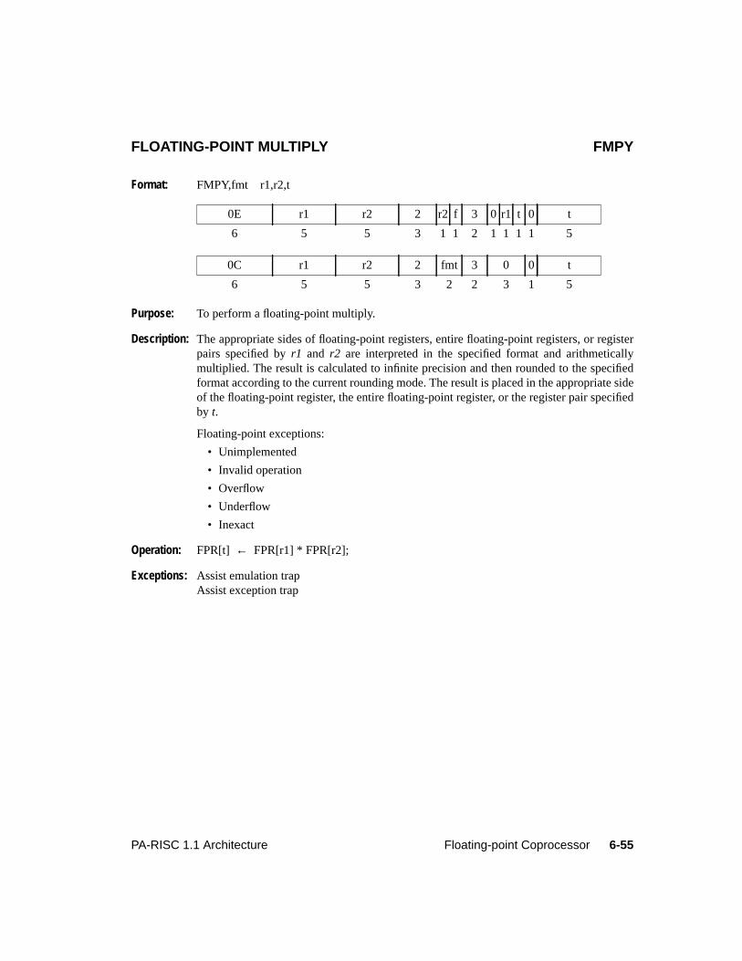
6-55PA-RISC 1.1 Architecture Floating-point Coprocessor
FLOATING-POINT MULTIPLY FMPY
Format: FMPY,fmt r1,r2,t
Purpose: To perform a floating-point multiply.
Description: The appropriate sides of floating-point registers, entire floating-point registers, or registerpairs specified byr1 and r2 are interpreted in the specified format and arithmeticallymultiplied. The result is calculated to infinite precision and then rounded to the specifiedformat according to the current rounding mode. The result is placed in the appropriate sideof the floating-point register, the entire floating-point register, or the register pair specifiedby t.
Floating-point exceptions:
• Unimplemented
• Invalid operation
• Overflow
• Underflow
• Inexact
Operation: FPR[t] ← FPR[r1] * FPR[r2];
Exceptions: Assist emulation trapAssist exception trap
0E r1 r2 2 r2 f 3 0 r1 t 0 t
6 5 5 3 1 1 2 1 1 1 1 5
0C r1 r2 2 fmt 3 0 0 t
6 5 5 3 2 2 3 1 5
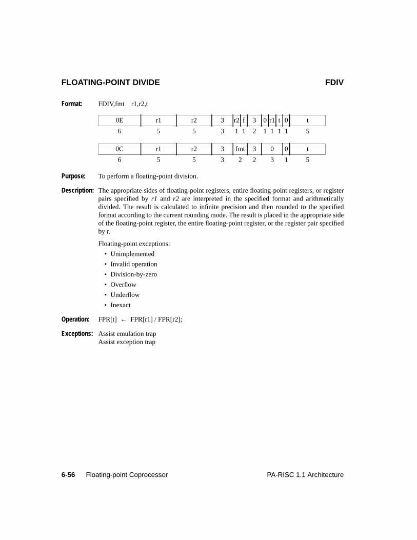
6-56 Floating-point Coprocessor PA-RISC 1.1 Architecture
FLOATING-POINT DIVIDE FDIV
Format: FDIV,fmt r1,r2,t
Purpose: To perform a floating-point division.
Description: The appropriate sides of floating-point registers, entire floating-point registers, or registerpairs specified byr1 and r2 are interpreted in the specified format and arithmeticallydivided. The result is calculated to infinite precision and then rounded to the specifiedformat according to the current rounding mode. The result is placed in the appropriate sideof the floating-point register, the entire floating-point register, or the register pair specifiedby t.
Floating-point exceptions:
• Unimplemented
• Invalid operation
• Division-by-zero
• Overflow
• Underflow
• Inexact
Operation: FPR[t] ← FPR[r1] / FPR[r2];
Exceptions: Assist emulation trapAssist exception trap
0E r1 r2 3 r2 f 3 0 r1 t 0 t
6 5 5 3 1 1 2 1 1 1 1 5
0C r1 r2 3 fmt 3 0 0 t
6 5 5 3 2 2 3 1 5
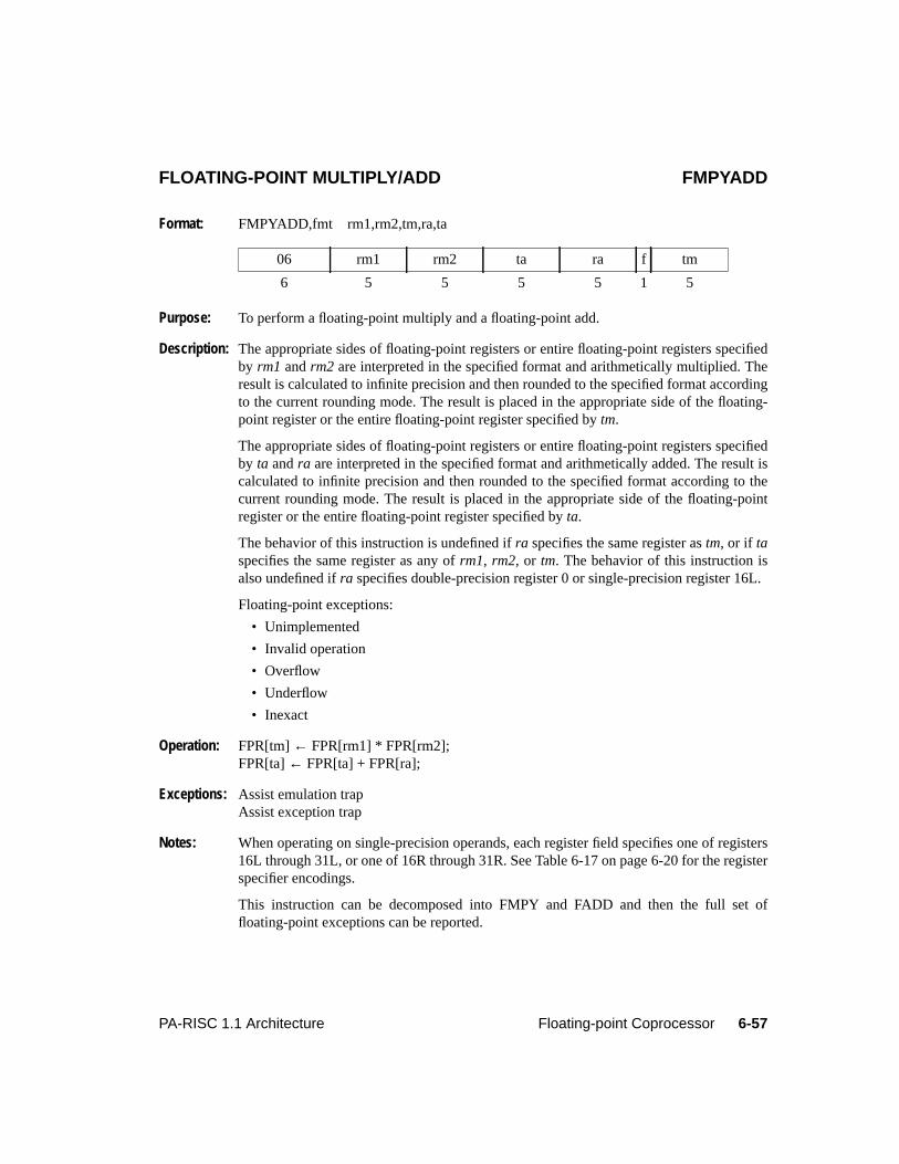
6-57PA-RISC 1.1 Architecture Floating-point Coprocessor
FLOATING-POINT MULTIPLY/ADD FMPYADD
Format: FMPYADD,fmt rm1,rm2,tm,ra,ta
Purpose: To perform a floating-point multiply and a floating-point add.
Description: The appropriate sides of floating-point registers or entire floating-point registers specifiedby rm1 andrm2 are interpreted in the specified format and arithmetically multiplied. Theresult is calculated to infinite precision and then rounded to the specified format accordingto the current rounding mode. The result is placed in the appropriate side of the floating-point register or the entire floating-point register specified bytm.
The appropriate sides of floating-point registers or entire floating-point registers specifiedby ta andra are interpreted in the specified format and arithmetically added. The result iscalculated to infinite precision and then rounded to the specified format according to thecurrent rounding mode. The result is placed in the appropriate side of the floating-pointregister or the entire floating-point register specified byta.
The behavior of this instruction is undefined ifra specifies the same register astm, or if taspecifies the same register as any ofrm1, rm2, or tm. The behavior of this instruction isalso undefined ifra specifies double-precision register 0 or single-precision register 16L.
Floating-point exceptions:
• Unimplemented
• Invalid operation
• Overflow
• Underflow
• Inexact
Operation: FPR[tm]← FPR[rm1] * FPR[rm2];FPR[ta]← FPR[ta] + FPR[ra];
Exceptions: Assist emulation trapAssist exception trap
Notes: When operating on single-precision operands, each register field specifies one of registers16L through 31L, or one of 16R through 31R. See Table 6-17 on page 6-20 for the registerspecifier encodings.
This instruction can be decomposed into FMPY and FADD and then the full set offloating-point exceptions can be reported.
06 rm1 rm2 ta ra f tm
6 5 5 5 5 1 5
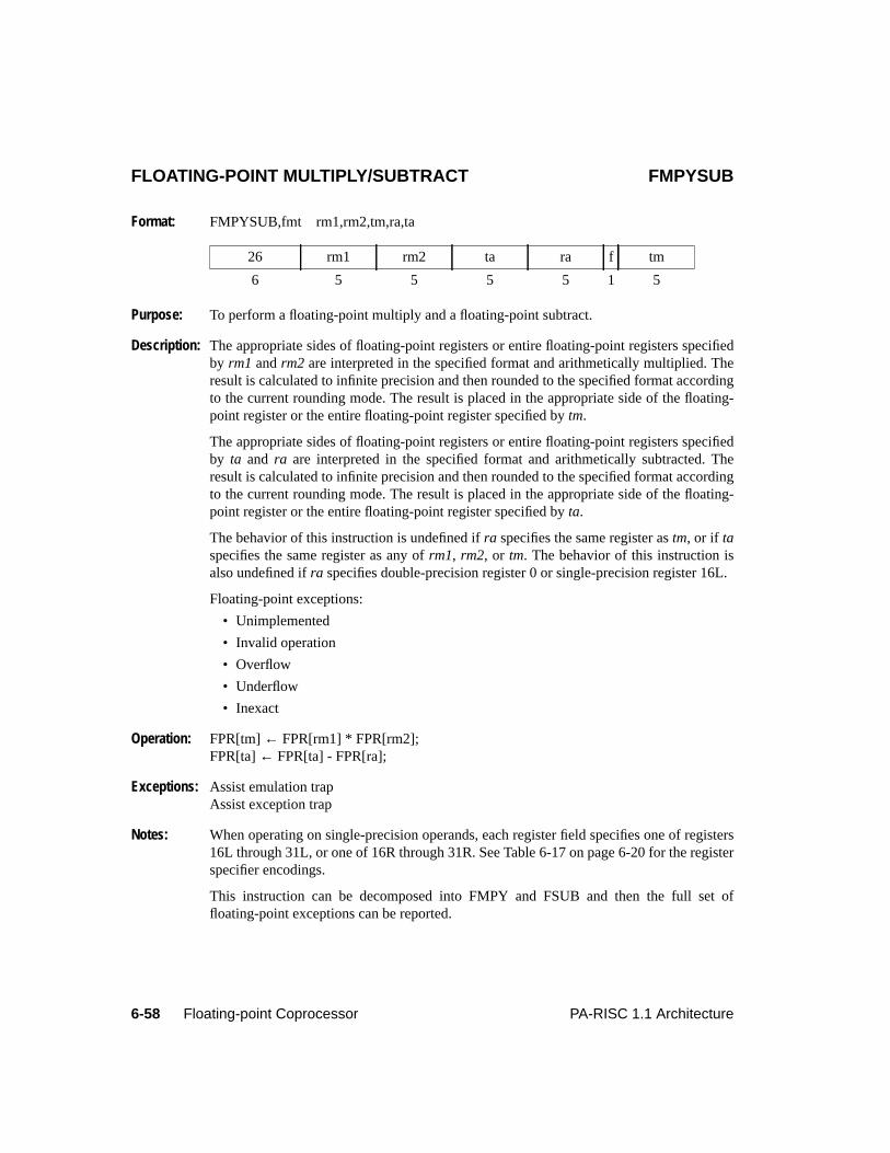
6-58 Floating-point Coprocessor PA-RISC 1.1 Architecture
FLOATING-POINT MULTIPLY/SUBTRACT FMPYSUB
Format: FMPYSUB,fmt rm1,rm2,tm,ra,ta
Purpose: To perform a floating-point multiply and a floating-point subtract.
Description: The appropriate sides of floating-point registers or entire floating-point registers specifiedby rm1 andrm2 are interpreted in the specified format and arithmetically multiplied. Theresult is calculated to infinite precision and then rounded to the specified format accordingto the current rounding mode. The result is placed in the appropriate side of the floating-point register or the entire floating-point register specified bytm.
The appropriate sides of floating-point registers or entire floating-point registers specifiedby ta and ra are interpreted in the specified format and arithmetically subtracted. Theresult is calculated to infinite precision and then rounded to the specified format accordingto the current rounding mode. The result is placed in the appropriate side of the floating-point register or the entire floating-point register specified byta.
The behavior of this instruction is undefined ifra specifies the same register astm, or if taspecifies the same register as any ofrm1, rm2, or tm. The behavior of this instruction isalso undefined ifra specifies double-precision register 0 or single-precision register 16L.
Floating-point exceptions:
• Unimplemented
• Invalid operation
• Overflow
• Underflow
• Inexact
Operation: FPR[tm]← FPR[rm1] * FPR[rm2];FPR[ta]← FPR[ta] - FPR[ra];
Exceptions: Assist emulation trapAssist exception trap
Notes: When operating on single-precision operands, each register field specifies one of registers16L through 31L, or one of 16R through 31R. See Table 6-17 on page 6-20 for the registerspecifier encodings.
This instruction can be decomposed into FMPY and FSUB and then the full set offloating-point exceptions can be reported.
26 rm1 rm2 ta ra f tm
6 5 5 5 5 1 5
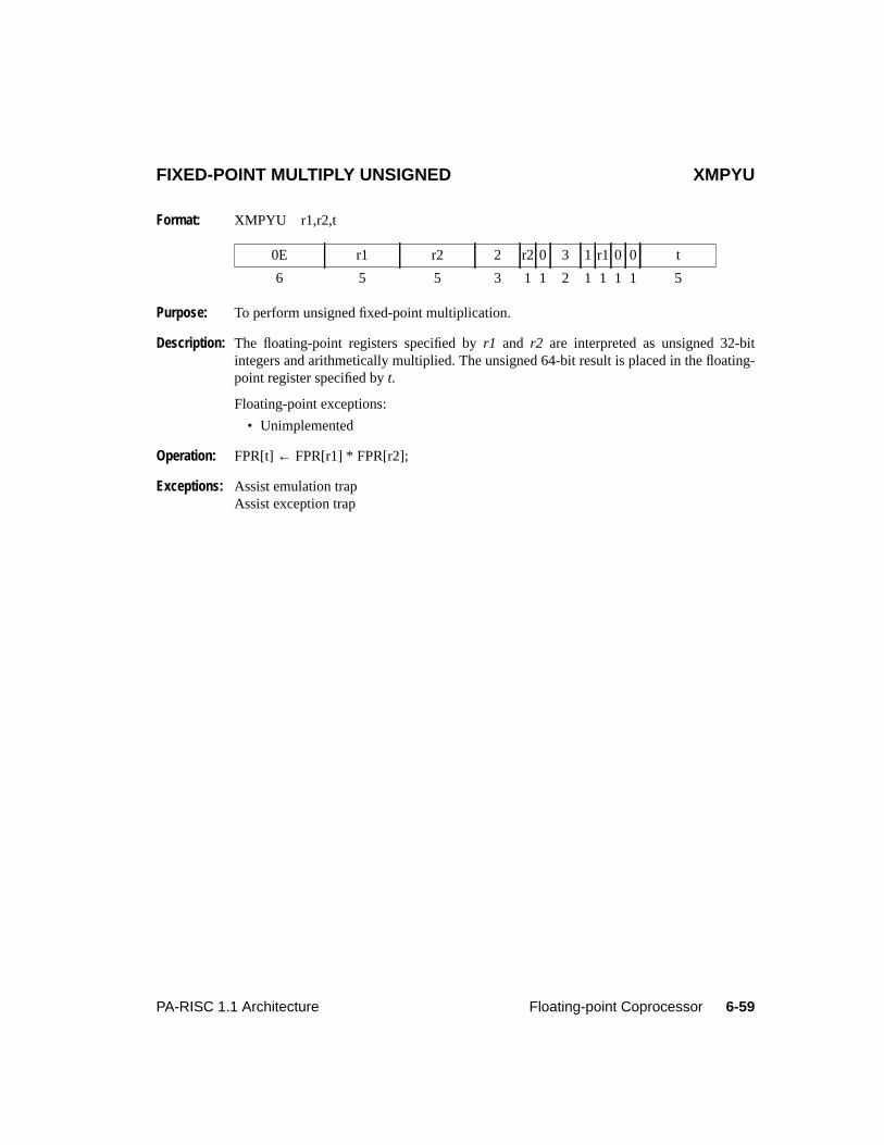
6-59PA-RISC 1.1 Architecture Floating-point Coprocessor
FIXED-POINT MULTIPLY UNSIGNED XMPYU
Format: XMPYU r1,r2,t
Purpose: To perform unsigned fixed-point multiplication.
Description: The floating-point registers specified byr1 and r2 are interpreted as unsigned 32-bitintegers and arithmetically multiplied. The unsigned 64-bit result is placed in the floating-point register specified byt.
Floating-point exceptions:
• Unimplemented
Operation: FPR[t] ← FPR[r1] * FPR[r2];
Exceptions: Assist emulation trapAssist exception trap
0E r1 r2 2 r2 0 3 1 r1 0 0 t
6 5 5 3 1 1 2 1 1 1 1 5
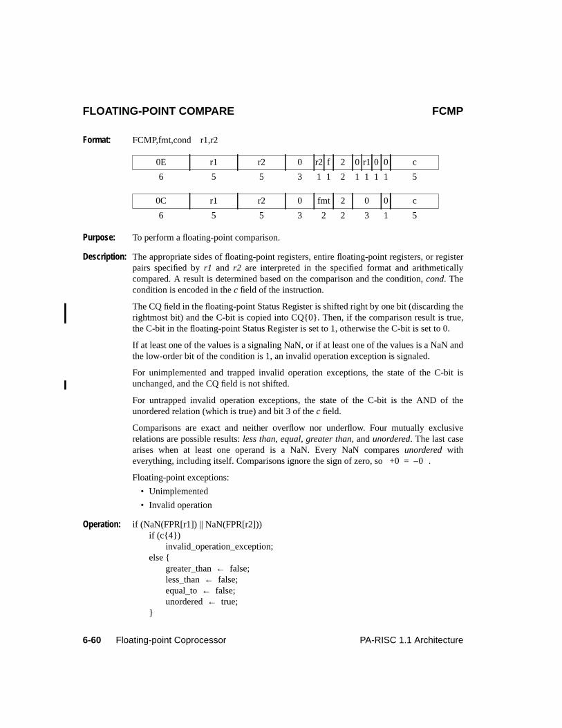
6-60 Floating-point Coprocessor PA-RISC 1.1 Architecture
6Floating-point CoprocessorFLOATING-POINT COMPARE FCMP
Format: FCMP,fmt,cond r1,r2
Purpose: To perform a floating-point comparison.
Description: The appropriate sides of floating-point registers, entire floating-point registers, or registerpairs specified byr1 and r2 are interpreted in the specified format and arithmeticallycompared. A result is determined based on the comparison and the condition,cond. Thecondition is encoded in thec field of the instruction.
The CQ field in the floating-point Status Register is shifted right by one bit (discarding therightmost bit) and the C-bit is copied into CQ{0}. Then, if the comparison result is true,the C-bit in the floating-point Status Register is set to 1, otherwise the C-bit is set to 0.
If at least one of the values is a signaling NaN, or if at least one of the values is a NaN andthe low-order bit of the condition is 1, an invalid operation exception is signaled.
For unimplemented and trapped invalid operation exceptions, the state of the C-bit isunchanged, and the CQ field is not shifted.
For untrapped invalid operation exceptions, the state of the C-bit is the AND of theunordered relation (which is true) and bit 3 of thec field.
Comparisons are exact and neither overflow nor underflow. Four mutually exclusiverelations are possible results:less than, equal, greater than, andunordered. The last casearises when at least one operand is a NaN. Every NaN comparesunordered witheverything, including itself. Comparisons ignore the sign of zero, so .
Floating-point exceptions:
• Unimplemented
• Invalid operation
Operation: if (NaN(FPR[r1]) || NaN(FPR[r2]))if (c{4})
invalid_operation_exception;else {
greater_than← false;less_than← false;equal_to← false;unordered← true;
}
0E r1 r2 0 r2 f 2 0 r1 0 0 c
6 5 5 3 1 1 2 1 1 1 1 5
0C r1 r2 0 fmt 2 0 0 c
6 5 5 3 2 2 3 1 5
+0 0–=
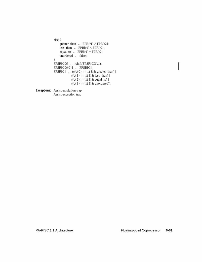
6-61PA-RISC 1.1 Architecture Floating-point Coprocessor
else {greater_than← FPR[r1] > FPR[r2];less_than← FPR[r1] < FPR[r2];equal_to← FPR[r1] = FPR[r2];unordered← false;
}FPSR[CQ] ← rshift(FPSR[CQ],1);FPSR[CQ{0}] ← FPSR[C];FPSR[C] ← (((c{0} == 1) && greater_than) ||
((c{1} == 1) && less_than) ||((c{2} == 1) && equal_to) ||((c{3} == 1) && unordered));
Exceptions: Assist emulation trapAssist exception trap
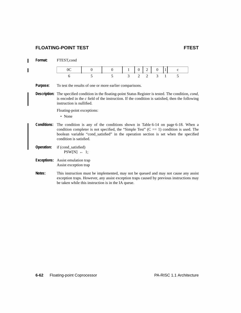
6-62 Floating-point Coprocessor PA-RISC 1.1 Architecture
FLOATING-POINT TEST FTEST
Format: FTEST,cond
Purpose: To test the results of one or more earlier comparisons.
Description: The specified condition in the floating-point Status Register is tested. The condition,cond,is encoded in thec field of the instruction. If the condition is satisfied, then the followinginstruction is nullified.
Floating-point exceptions:
• None
Conditions: The condition is any of the conditions shown in Table 6-14 on page 6-18. When acondition completer is not specified, the “Simple Test” (C == 1) condition is used. Theboolean variable “cond_satisfied” in the operation section is set when the specifiedcondition is satisfied.
Operation: if (cond_satisfied)PSW[N] ← 1;
Exceptions: Assist emulation trapAssist exception trap
Notes: This instruction must be implemented, may not be queued and may not cause any assistexception traps. However, any assist exception traps caused by previous instructions maybe taken while this instruction is in the IA queue.
0C 0 0 1 0 2 0 1 c
6 5 5 3 2 2 3 1 5
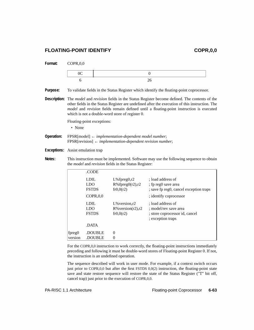
6-63PA-RISC 1.1 Architecture Floating-point Coprocessor
6Floating-point CoprocessorFLOATING-POINT IDENTIFY COPR,0,0
Format: COPR,0,0
Purpose: To validate fields in the Status Register which identify the floating-point coprocessor.
Description: Themodel andrevision fields in the Status Register become defined. The contents of theother fields in the Status Register are undefined after the execution of this instruction. Themodel and revision fields remain defined until a floating-point instruction is executedwhich is not a double-word store of register 0.
Floating-point exceptions:
• None
Operation: FPSR[model]← implementation-dependent model number;FPSR[revision]← implementation-dependent revision number;
Exceptions: Assist emulation trap
Notes: This instruction must be implemented. Software may use the following sequence to obtainthemodel andrevision fields in the Status Register:
For theCOPR,0,0 instruction to work correctly, the floating-point instructions immediatelypreceding and following it must be double-word stores of Floating-point Register 0. If not,the instruction is an undefined operation.
The sequence described will work in user mode. For example, if a context switch occursjust prior toCOPR,0,0 but after the firstFSTDS 0,0(2) instruction, the floating-point statesave and state restore sequence will restore the state of the Status Register ("T" bit off,cancel trap) just prior to the execution ofCOPR,0,0.
0C 0
6 26
.CODE
LDIL L%fpreg0,r2 ; load address ofLDO R%fpreg0(r2),r2 ; fp reg0 save areaFSTDS fr0,0(r2) ; save fp reg0, cancel exception traps
COPR,0,0 ; identify coprocessor
LDIL L%version,r2 ; load address ofLDO R%version(r2),r2 ; model/rev save areaFSTDS fr0,0(r2) ; store coprocessor id, cancel
; exception traps
.DATA
fpreg0 .DOUBLE 0version .DOUBLE 0

6-64 Floating-point Coprocessor PA-RISC 1.1 Architecture
7-1PA-RISC 1.1 Architecture Performance Monitor Coprocessor
7 Performance Monitor Coprocessor
IntroductionThis chapter describes the architecture for the performance monitor coprocessor.
The performance monitor coprocessor is an optional, implementation-dependent coprocessor whichprovides a minimal common software interface to implementation-dependent performance monitorhardware.
The performance monitor coprocessor responds to coprocessor instructions with a uid equal to 2.
The Instruction SetThe performance monitor instruction set consists of two instructions,PERFORMANCE MONITORENABLE (PMENB) and PERFORMANCE MONITOR DISABLE (PMDIS), which provide a commonsoftware interface to enable and disable the implementation-dependent performance monitor features.
Figure 7-1 shows the format of these operations and Table 7-1 shows the operations, their mnemonics,and sub-opcodes:
Interruptions
Performance Monitor InterruptionInterruption vector number 29 in interruption group 2 is defined as the performance monitorcoprocessor interrupt for implementation-dependent use by the performance monitor coprocessor. Theinterrupt is unmasked when the PSW F-bit is 1, and is masked when the PSW F-bit is 0. See“Interruptions” on page 4-13 for additional details.
0C rv sub 2 n rv
6 12 5 3 1 5
Figure 7-1. Performance Monitor Operation Format
Table 7-1. Performance Monitor Operations
Opcode Sub-op Mnemonic Operation
0C 1 PMDIS Disable performance monitor0C 3 PMENB Enable performance monitor0C 0,2,4..1F undefined
7-2 Performance Monitor Coprocessor PA-RISC 1.1 Architecture
Monitor UnitsThe monitor units are hardware units used to collect the necessary information during performancemonitoring. The number of the monitor units and their hardware types are implementation dependent.
If a monitor unit provides counters, the most significant bit of the counter is required to be an overflowindicator. The bit must be set when the counter overflows and must remain set until explicitly reset bysoftware. When the overflow indicator is set the remaining bits of the counter are undefined.
NOTEIf counters are used to implement the measurement units, it is recommended that the countersbe at least 32 bits wide.
Instruction Set DescriptionThe following pages describe the performance monitor coprocessor instructions.
When a performance monitor coprocessor instruction is executed and CCR{2} is 0, the coprocessorinstruction causes an assist emulation trap. It is an undefined operation to set CCR{2} to 1 if theperformance monitor coprocessor is nonexistent.
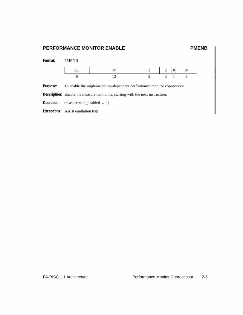
7-3PA-RISC 1.1 Architecture Performance Monitor Coprocessor
PERFORMANCE MONITOR ENABLE PMENB
Format: PMENB
Purpose: To enable the implementation-dependent performance monitor coprocessor.
Description: Enable the measurement units, starting with the next instruction.
Operation: measurement_enabled← 1;
Exceptions: Assist emulation trap
0C rv 3 2 0 rv
6 12 5 3 1 5
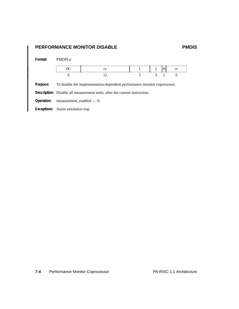
7-4 Performance Monitor Coprocessor PA-RISC 1.1 Architecture
PERFORMANCE MONITOR DISABLE PMDIS
Format: PMDIS,n
Purpose: To disable the implementation-dependent performance monitor coprocessor.
Description: Disable all measurement units, after the current instruction.
Operation: measurement_enabled← 0;
Exceptions: Assist emulation trap
0C rv 1 2 0 rv
6 12 5 3 1 5
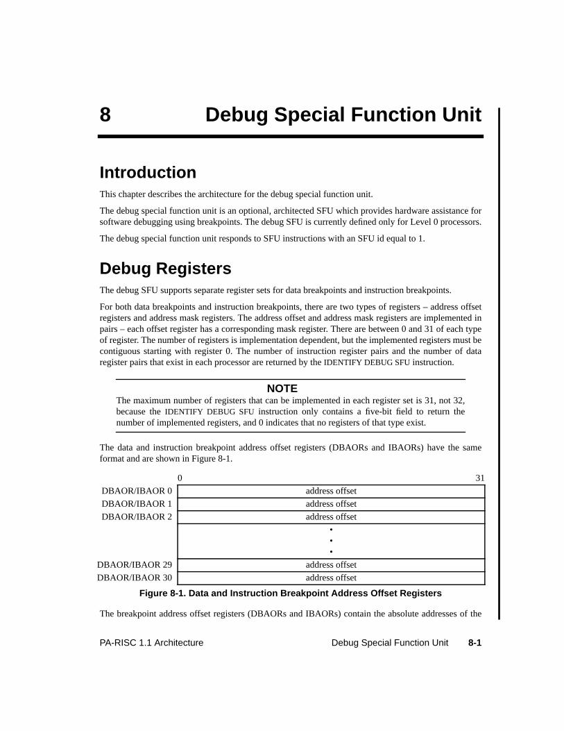
8-1PA-RISC 1.1 Architecture Debug Special Function Unit
8 Debug Special Function Unit
IntroductionThis chapter describes the architecture for the debug special function unit.
The debug special function unit is an optional, architected SFU which provides hardware assistance forsoftware debugging using breakpoints. The debug SFU is currently defined only for Level 0 processors.
The debug special function unit responds to SFU instructions with an SFU id equal to 1.
Debug RegistersThe debug SFU supports separate register sets for data breakpoints and instruction breakpoints.
For both data breakpoints and instruction breakpoints, there are two types of registers – address offsetregisters and address mask registers. The address offset and address mask registers are implemented inpairs – each offset register has a corresponding mask register. There are between 0 and 31 of each typeof register. The number of registers is implementation dependent, but the implemented registers must becontiguous starting with register 0. The number of instruction register pairs and the number of dataregister pairs that exist in each processor are returned by theIDENTIFY DEBUG SFU instruction.
NOTEThe maximum number of registers that can be implemented in each register set is 31, not 32,because theIDENTIFY DEBUG SFU instruction only contains a five-bit field to return thenumber of implemented registers, and 0 indicates that no registers of that type exist.
The data and instruction breakpoint address offset registers (DBAORs and IBAORs) have the sameformat and are shown in Figure 8-1.
The breakpoint address offset registers (DBAORs and IBAORs) contain the absolute addresses of the
0 31
DBAOR/IBAOR 0 address offset
DBAOR/IBAOR 1 address offset
DBAOR/IBAOR 2 address offset
•••
DBAOR/IBAOR 29 address offset
DBAOR/IBAOR 30 address offset
Figure 8-1. Data and Instruction Breakpoint Address Offset Registers
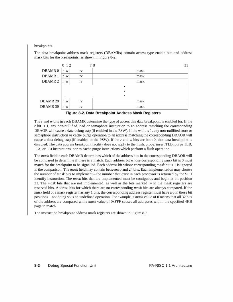
8-2 Debug Special Function Unit PA-RISC 1.1 Architecture
breakpoints.
The data breakpoint address mask registers (DBAMRs) contain access-type enable bits and addressmask bits for the breakpoints, as shown in Figure 8-2.
Ther andw bits in each DBAMR determine the type of access this data breakpoint is enabled for. If ther bit is 1, any non-nullified load or semaphore instruction to an address matching the correspondingDBAOR will cause a data debug trap (if enabled in the PSW). If thew bit is 1, any non-nullified store orsemaphore instruction or cache purge operation to an address matching the corresponding DBAOR willcause a data debug trap (if enabled in the PSW). If ther andw bits are both 0, that data breakpoint isdisabled. The data address breakpoint facility does not apply to the flush, probe, insert TLB, purge TLB,LPA, or LCI instructions, nor to cache purge instructions which perform a flush operation.
Themask field in each DBAMR determines which of the address bits in the corresponding DBAOR willbe compared to determine if there is a match. Each address bit whose correspondingmask bit is 0 mustmatch for the breakpoint to be signalled. Each address bit whose correspondingmask bit is 1 is ignoredin the comparison. Themask field may contain between 0 and 24 bits. Each implementation may choosethe number ofmask bits to implement – the number that exist in each processor is returned by the SFUidentify instruction. Themask bits that are implemented must be contiguous and begin at bit position31. Themask bits that are not implemented, as well as the bits markedrv in the mask registers arereserved bits. Address bits for which there are no correspondingmask bits are always compared. If themask field of a mask register has any 1 bits, the corresponding address register must have a 0 in those bitpositions – not doing so is an undefined operation. For example, amask value of 0 means that all 32 bitsof the address are compared whilemask value of 0xFFF causes all addresses within the specified 4KBpage to match.
The instruction breakpoint address mask registers are shown in Figure 8-3.
0 1 2 7 8 31
DBAMR 0 r w rv mask
DBAMR 1 r w rv mask
DBAMR 2 r w rv mask
•••
DBAMR 29 r w rv mask
DBAMR 30 r w rv mask
Figure 8-2. Data Breakpoint Address Mask Registers
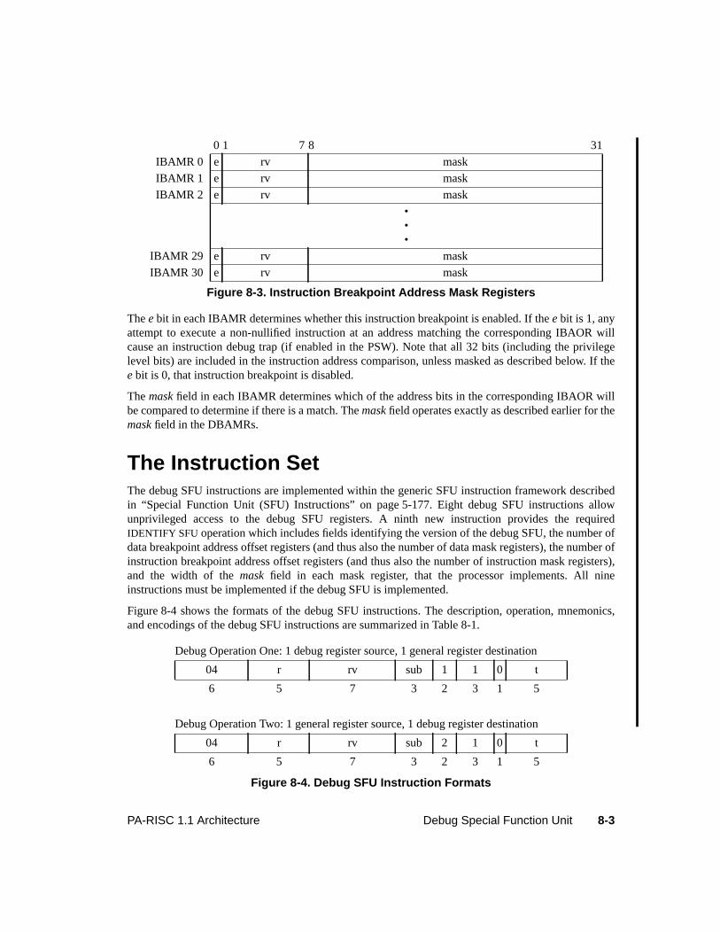
8-3PA-RISC 1.1 Architecture Debug Special Function Unit
Thee bit in each IBAMR determines whether this instruction breakpoint is enabled. If thee bit is 1, anyattempt to execute a non-nullified instruction at an address matching the corresponding IBAOR willcause an instruction debug trap (if enabled in the PSW). Note that all 32 bits (including the privilegelevel bits) are included in the instruction address comparison, unless masked as described below. If thee bit is 0, that instruction breakpoint is disabled.
Themask field in each IBAMR determines which of the address bits in the corresponding IBAOR willbe compared to determine if there is a match. Themask field operates exactly as described earlier for themask field in the DBAMRs.
The Instruction SetThe debug SFU instructions are implemented within the generic SFU instruction framework describedin “Special Function Unit (SFU) Instructions” on page 5-177. Eight debug SFU instructions allowunprivileged access to the debug SFU registers. A ninth new instruction provides the requiredIDENTIFY SFU operation which includes fields identifying the version of the debug SFU, the number ofdata breakpoint address offset registers (and thus also the number of data mask registers), the number ofinstruction breakpoint address offset registers (and thus also the number of instruction mask registers),and the width of themask field in each mask register, that the processor implements. All nineinstructions must be implemented if the debug SFU is implemented.
Figure 8-4 shows the formats of the debug SFU instructions. The description, operation, mnemonics,and encodings of the debug SFU instructions are summarized in Table 8-1.
0 1 7 8 31
IBAMR 0 e rv mask
IBAMR 1 e rv mask
IBAMR 2 e rv mask
•••
IBAMR 29 e rv mask
IBAMR 30 e rv mask
Figure 8-3. Instruction Breakpoint Address Mask Registers
Debug Operation One: 1 debug register source, 1 general register destination
04 r rv sub 1 1 0 t
6 5 7 3 2 3 1 5
Debug Operation Two: 1 general register source, 1 debug register destination
04 r rv sub 2 1 0 t
6 5 7 3 2 3 1 5
Figure 8-4. Debug SFU Instruction Formats
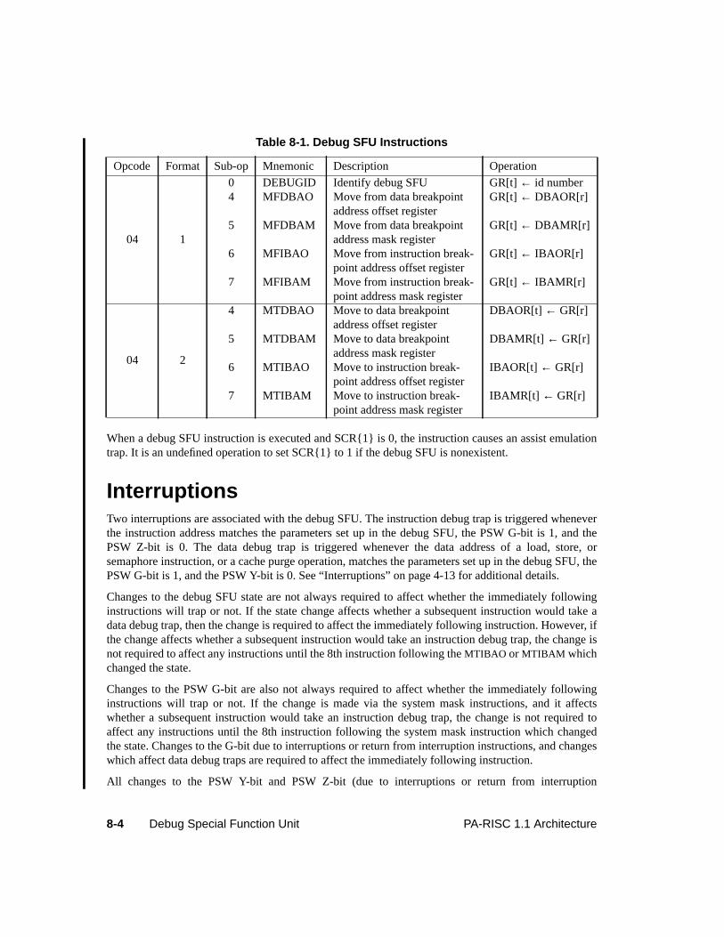
8-4 Debug Special Function Unit PA-RISC 1.1 Architecture
When a debug SFU instruction is executed and SCR{1} is 0, the instruction causes an assist emulationtrap. It is an undefined operation to set SCR{1} to 1 if the debug SFU is nonexistent.
InterruptionsTwo interruptions are associated with the debug SFU. The instruction debug trap is triggered wheneverthe instruction address matches the parameters set up in the debug SFU, the PSW G-bit is 1, and thePSW Z-bit is 0. The data debug trap is triggered whenever the data address of a load, store, orsemaphore instruction, or a cache purge operation, matches the parameters set up in the debug SFU, thePSW G-bit is 1, and the PSW Y-bit is 0. See “Interruptions” on page 4-13 for additional details.
Changes to the debug SFU state are not always required to affect whether the immediately followinginstructions will trap or not. If the state change affects whether a subsequent instruction would take adata debug trap, then the change is required to affect the immediately following instruction. However, ifthe change affects whether a subsequent instruction would take an instruction debug trap, the change isnot required to affect any instructions until the 8th instruction following theMTIBAO or MTIBAM whichchanged the state.
Changes to the PSW G-bit are also not always required to affect whether the immediately followinginstructions will trap or not. If the change is made via the system mask instructions, and it affectswhether a subsequent instruction would take an instruction debug trap, the change is not required toaffect any instructions until the 8th instruction following the system mask instruction which changedthe state. Changes to the G-bit due to interruptions or return from interruption instructions, and changeswhich affect data debug traps are required to affect the immediately following instruction.
All changes to the PSW Y-bit and PSW Z-bit (due to interruptions or return from interruption
Table 8-1. Debug SFU Instructions
Opcode Format Sub-op Mnemonic Description Operation
04 1
0 DEBUGID Identify debug SFU GR[t]← id number4 MFDBAO Move from data breakpoint
address offset registerGR[t] ← DBAOR[r]
5 MFDBAM Move from data breakpointaddress mask register
GR[t] ← DBAMR[r]
6 MFIBAO Move from instruction break-point address offset register
GR[t] ← IBAOR[r]
7 MFIBAM Move from instruction break-point address mask register
GR[t] ← IBAMR[r]
04 2
4 MTDBAO Move to data breakpointaddress offset register
DBAOR[t] ← GR[r]
5 MTDBAM Move to data breakpointaddress mask register
DBAMR[t] ← GR[r]
6 MTIBAO Move to instruction break-point address offset register
IBAOR[t] ← GR[r]
7 MTIBAM Move to instruction break-point address mask register
IBAMR[t] ← GR[r]
8-5PA-RISC 1.1 Architecture Debug Special Function Unit
instructions) are required to affect the immediately following instructions.
Instruction Set DescriptionThe following pages describe the debug SFU instructions.
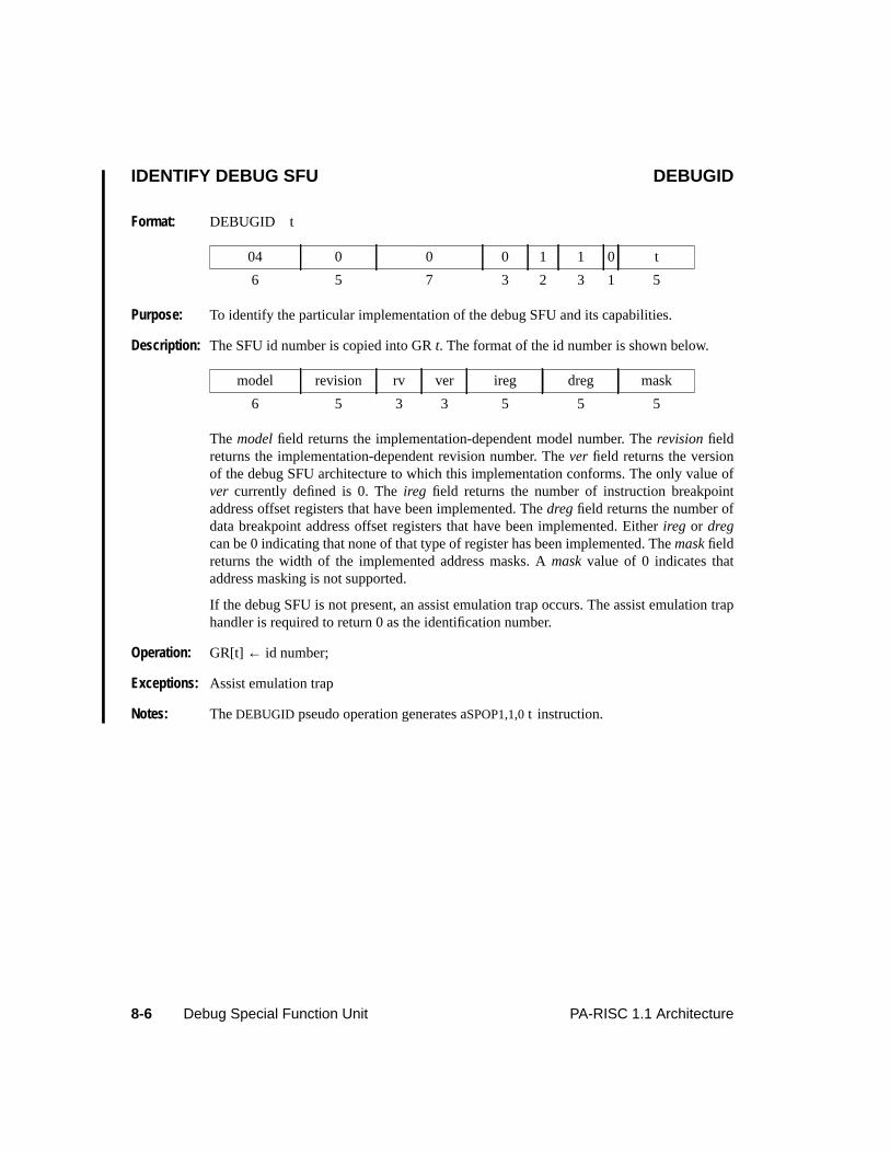
8-6 Debug Special Function Unit PA-RISC 1.1 Architecture
IDENTIFY DEBUG SFU DEBUGID
Format: DEBUGID t
Purpose: To identify the particular implementation of the debug SFU and its capabilities.
Description: The SFU id number is copied into GRt. The format of the id number is shown below.
The model field returns the implementation-dependent model number. Therevision fieldreturns the implementation-dependent revision number. Thever field returns the versionof the debug SFU architecture to which this implementation conforms. The only value ofver currently defined is 0. Theireg field returns the number of instruction breakpointaddress offset registers that have been implemented. Thedreg field returns the number ofdata breakpoint address offset registers that have been implemented. Eitherireg or dregcan be 0 indicating that none of that type of register has been implemented. Themask fieldreturns the width of the implemented address masks. Amask value of 0 indicates thataddress masking is not supported.
If the debug SFU is not present, an assist emulation trap occurs. The assist emulation traphandler is required to return 0 as the identification number.
Operation: GR[t] ← id number;
Exceptions: Assist emulation trap
Notes: The DEBUGID pseudo operation generates aSPOP1,1,0 t instruction.
04 0 0 0 1 1 0 t
6 5 7 3 2 3 1 5
model revision rv ver ireg dreg mask
6 5 3 3 5 5 5
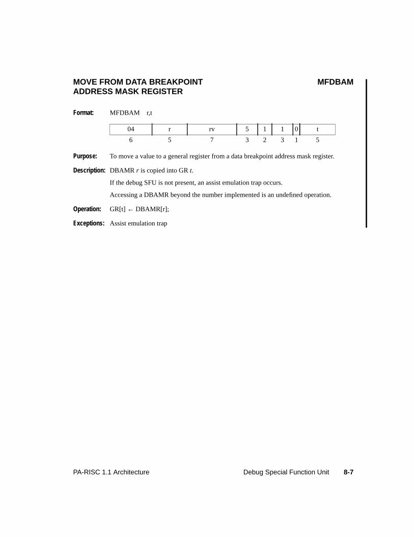
8-7PA-RISC 1.1 Architecture Debug Special Function Unit
MOVE FROM DATA BREAKPOINT MFDBAMADDRESS MASK REGISTER
Format: MFDBAM r,t
Purpose: To move a value to a general register from a data breakpoint address mask register.
Description: DBAMR r is copied into GRt.
If the debug SFU is not present, an assist emulation trap occurs.
Accessing a DBAMR beyond the number implemented is an undefined operation.
Operation: GR[t] ← DBAMR[r];
Exceptions: Assist emulation trap
04 r rv 5 1 1 0 t
6 5 7 3 2 3 1 5
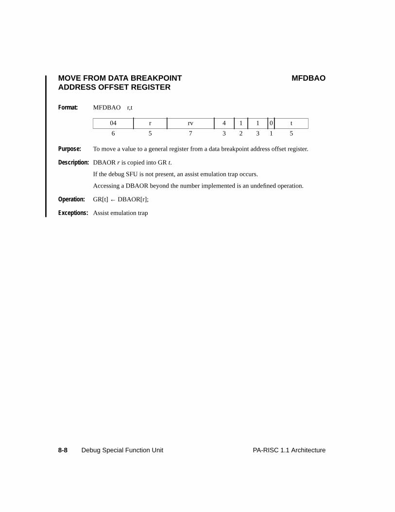
8-8 Debug Special Function Unit PA-RISC 1.1 Architecture
MOVE FROM DATA BREAKPOINT MFDBAOADDRESS OFFSET REGISTER
Format: MFDBAO r,t
Purpose: To move a value to a general register from a data breakpoint address offset register.
Description: DBAOR r is copied into GRt.
If the debug SFU is not present, an assist emulation trap occurs.
Accessing a DBAOR beyond the number implemented is an undefined operation.
Operation: GR[t] ← DBAOR[r];
Exceptions: Assist emulation trap
04 r rv 4 1 1 0 t
6 5 7 3 2 3 1 5
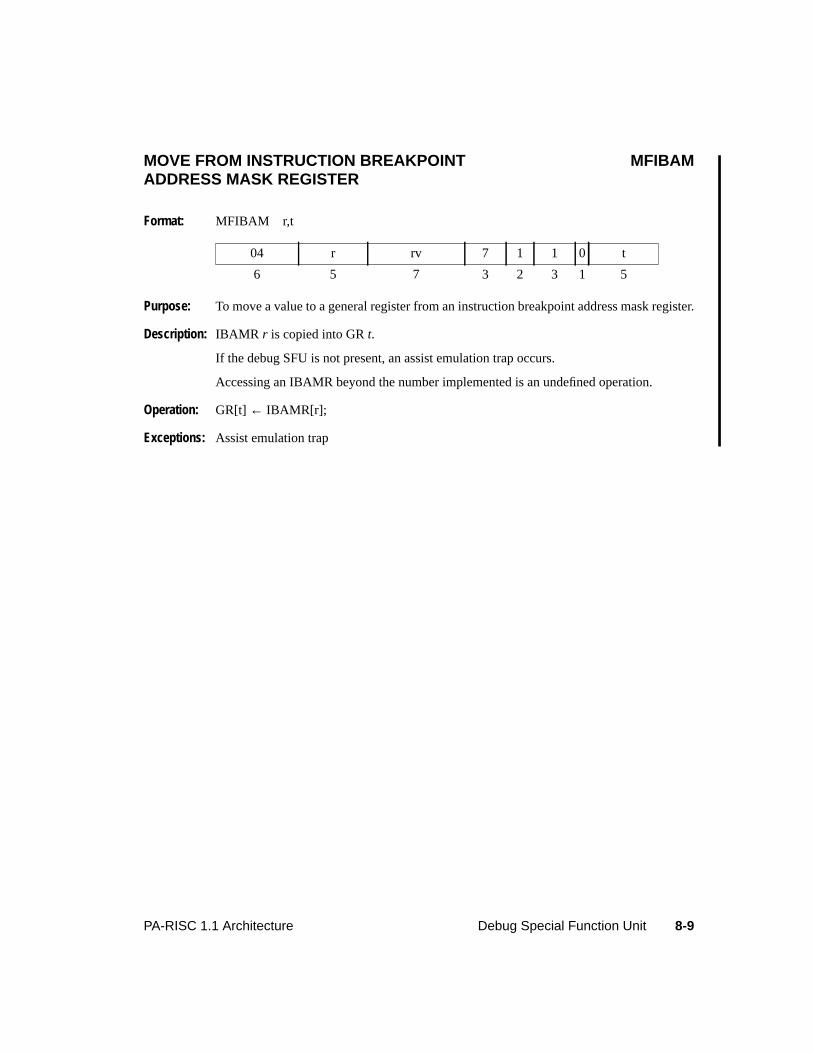
8-9PA-RISC 1.1 Architecture Debug Special Function Unit
MOVE FROM INSTRUCTION BREAKPOINT MFIBAMADDRESS MASK REGISTER
Format: MFIBAM r,t
Purpose: To move a value to a general register from an instruction breakpoint address mask register.
Description: IBAMR r is copied into GRt.
If the debug SFU is not present, an assist emulation trap occurs.
Accessing an IBAMR beyond the number implemented is an undefined operation.
Operation: GR[t] ← IBAMR[r];
Exceptions: Assist emulation trap
04 r rv 7 1 1 0 t
6 5 7 3 2 3 1 5
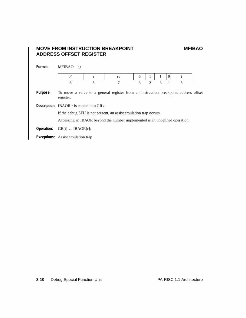
8-10 Debug Special Function Unit PA-RISC 1.1 Architecture
MOVE FROM INSTRUCTION BREAKPOINT MFIBAOADDRESS OFFSET REGISTER
Format: MFIBAO r,t
Purpose: To move a value to a general register from an instruction breakpoint address offsetregister.
Description: IBAOR r is copied into GRt.
If the debug SFU is not present, an assist emulation trap occurs.
Accessing an IBAOR beyond the number implemented is an undefined operation.
Operation: GR[t] ← IBAOR[r];
Exceptions: Assist emulation trap
04 r rv 6 1 1 0 t
6 5 7 3 2 3 1 5
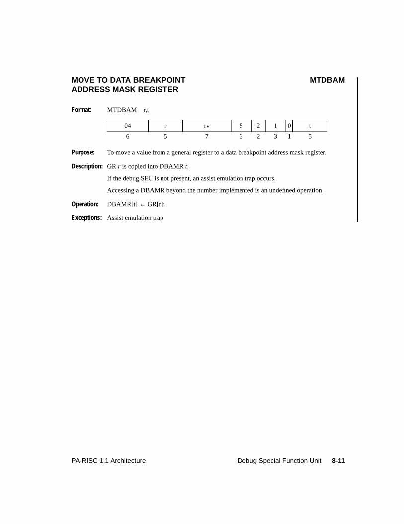
8-11PA-RISC 1.1 Architecture Debug Special Function Unit
MOVE TO DATA BREAKPOINT MTDBAMADDRESS MASK REGISTER
Format: MTDBAM r,t
Purpose: To move a value from a general register to a data breakpoint address mask register.
Description: GR r is copied into DBAMRt.
If the debug SFU is not present, an assist emulation trap occurs.
Accessing a DBAMR beyond the number implemented is an undefined operation.
Operation: DBAMR[t] ← GR[r];
Exceptions: Assist emulation trap
04 r rv 5 2 1 0 t
6 5 7 3 2 3 1 5
8-12 Debug Special Function Unit PA-RISC 1.1 Architecture
MOVE TO DATA BREAKPOINT MTDBAOADDRESS OFFSET REGISTER
Format: MTDBAO r,t
Purpose: To move a value from a general register to a data breakpoint address offset register.
Description: GR r is copied into DBAORt.
If the debug SFU is not present, an assist emulation trap occurs.
Accessing a DBAOR beyond the number implemented is an undefined operation.
Operation: DBAOR[t] ← GR[r];
Exceptions: Assist emulation trap
04 r rv 4 2 1 0 t
6 5 7 3 2 3 1 5
8-13PA-RISC 1.1 Architecture Debug Special Function Unit
MOVE TO INSTRUCTION BREAKPOINT MTIBAMADDRESS MASK REGISTER
Format: MTIBAM r,t
Purpose: To move a value from a general register to an instruction breakpoint address mask register.
Description: GR r is copied into IBAMRt.
If the debug SFU is not present, an assist emulation trap occurs.
Accessing an IBAMR beyond the number implemented is an undefined operation.
Operation: IBAMR[t] ← GR[r];
Exceptions: Assist emulation trap
04 r rv 7 2 1 0 t
6 5 7 3 2 3 1 5
8-14 Debug Special Function Unit PA-RISC 1.1 Architecture
MOVE TO INSTRUCTION BREAKPOINT MTIBAOADDRESS OFFSET REGISTER
Format: MTIBAO r,t
Purpose: To move a value from a general register to an instruction breakpoint address offsetregister.
Description: GR r is copied into IBAORt.
If the debug SFU is not present, an assist emulation trap occurs.
Accessing an IBAOR beyond the number implemented is an undefined operation.
Operation: IBAOR[t] ← GR[r];
Exceptions: Assist emulation trap
04 r rv 6 2 1 0 t
6 5 7 3 2 3 1 5
A-1PA-RISC 1.1 Architecture Glossary
A Glossary
Absolute Address
See Physical Address.
Access Rights
A function of virtual address translation that controls access to each page through privilege levelsfor read, write, execute, and gateway. The TLB contains, within each entry, information used todetermine who may have access to that page. This information is divided into two groups: (1) pageaccess (access ID) which is used to determine if a process or user may access a page; and (2) theaccess rights field that is combined with the user’s privilege level to determine if the type of accessthe user is requesting will be allowed.
Address
PA-RISC is a byte-addressable system which uses both virtual and absolute addresses. A virtualaddress can be split into two parts: the high-order bits which are the space identifier and the 32low-order bits that give the offset within the space. Absolute addresses do not have spaceidentifiers; only a 32-bit offset. Doublewords, words, and halfwords are always located ataddresses which are aligned to their size (in bytes). Quadwords are aligned on doublewordboundaries.
Address Translation
For a virtual memory system, the process whereby the virtual (logical) address of data orinstructions is translated to its absolute address in physical memory.
Aliasing
The condition when the same physical memory location is accessed by different virtual addressesor by both an absolute and a virtual address.
Alter
The action of setting the E-bit of a TLB entry to 0 and modifying some portion of the physicalpage number field. Altered entries in the TLB are still visible to software through the insert TLBprotection instructions.
Architecture
Refers to the time independent functional appearance of a computer system. An implementation ofan architecture is an ensemble of hardware, firmware, and software that provides all the functionsas defined in the architecture.
A-2 Glossary PA-RISC 1.1 Architecture
Arithmetic and Logical Unit (ALU)
The part of a PA-RISC processor that performs arithmetic and logic operations on its inputs,producing output and status information.
Assist Processor
A processor which may be added to the basic PA-RISC system to enhance performance orfunctionality for algorithms which experience substantial gains from the use of specializedhardware. Assist processors are differentiated by the level at which they interface with thememory hierarchy. (See special function units and coprocessors).
B-bit (Taken Branch in Previous Cycle)
A bit in the PSW that is 1 if the previous instruction was a taken branch.
Base Register
A register that holds the numeric value that is used as a base value in the calculation of addresses.Displacements or index values are added to this base value.
Base-Relative Branch
When a general register is used as the base offset to obtain the target address, the branch is calledbase relative.
Biased Exponent
The exponent field for a floating-point number. It consists of the exponent plus the bias.
Binary Floating-point Number
A number format consisting of the three components: sign, exponent, and significand.
Block TLB
A block TLB provides address translations which map address ranges larger than a page.
Byte
A group of eight contiguous bits which is the smallest addressable unit on a PA-RISC system.
C-bit (Code Address Translation Enable)
A bit in the PSW that specifies whether virtual address translation of the instruction address is tobe performed.
Cache
A high-speed buffer unit between main memory and the CPU. The cache is continually updated tocontain recently accessed contents of main memory to reduce access time. When a program makesa memory request, the CPU first checks to see if the data is in the cache so that it can be retrievedwithout accessing memory. There may be one cache for both instructions and data or separatecaches for each.
A-3PA-RISC 1.1 Architecture Glossary
Cache Coherence
The property of multiple caches whereby they provide identical shared memory images.Processors in a multiprocessor system are said to be cache coherent if they provide the image ofsingle cache.
Cache Control Hint
A 2-bit field in some memory reference instructions which provides a hint to the processor on howto resolve cache coherence. The processor may disregard the hint without compromising systemintegrity, but performance may be enhanced by following the hint.
Cache Miss
A cache miss occurs when the cache does not contain a copy of the cache line being requested bythe address. The cache is updated with data and re-accessed.
Carry/Borrow Bits
An 8-bit field in the PSW that indicates if a carry or borrow occurred from the correspondingnibble (4 bits) as a result of the previous arithmetic operation.
Central Processing Unit (CPU)
The part of a PA-RISC processor that fetches and executes instructions.
Check
The interruption condition when the processor detects an internal or external malfunction. Checksmay be either synchronous or asynchronous with respect to the instruction stream.
Coherence Check
An action taken by hardware to insure coherence.
Combined TLB
Some systems have a combined TLB which provides address translation for both instruction anddata references.
Compatibility
The ability for software developed for one machine type to execute on another machine type. PA-RISC provides compatible execution of application programs written for earlier-generationHewlett-Packard computer systems.
Completer
A machine instruction field used to specify instruction options. Typical options include addressmodification, address indexing, precision of operands, and conditions to be tested to determinewhether to nullify the following instruction.
A-4 Glossary PA-RISC 1.1 Architecture
Condition
The state of a value or a relationship between values used in determining whether an instruction isto branch, nullify, or trap.
Control Register (CR)
A register which contains system state information used for memory access protection,interruption control, and processor state control. A PA-RISC processor contains 25 controlregisters (7 more are reserved).
Coprocessor
A type of assist processor which interfaces to the memory hierarchy at the level of the cache.Coprocessors are special purpose units that work with the main processor to speed up specializedoperations such as floating-point arithmetic and graphics processing. Coprocessors generally havetheir own internal state and hardware evaluation mechanism.
Coprocessor Configuration Register (CCR)
The CCR (in CR 10) is an 8-bit register which records the presence and usability of coprocessors.Each bit position (0-7) corresponds to the coprocessor with the same unit number. Setting a bit inthe CCR to 1 enables the use of the corresponding coprocessor, if present and operational. If aCCR bit is 0, the corresponding coprocessor, if present, is logically decoupled and an attempt toreference the coprocessor causes an assist emulation trap.
Current Instruction
The instruction whose address is in the front element of the instruction address queues (IASQ andIAOQ).
D-bit (Data Address Translation Enable)
A bit in the PSW that specifies whether virtual address translation of data addresses is to beperformed.
Data Cache (D-cache)
A high-speed storage device which contains data items that have been recently accessed frommain memory. The D-cache can be accessed independently of the instruction cache (I-cache) andno synchronization is performed.
Data TLB (DTLB)
A separate TLB which does address translation only for data.
Denormalized Numbers
Any non-zero floating-point number with the exponent field all zeros. Denormalized numbers aredistinguished from normal numbers in that the value of the "hidden" bit to the left of the impliedbinary point is zero.
A-5PA-RISC 1.1 Architecture Glossary
Dirty
A block of memory (commonly a cache line or a page) which has been written to is referred to asdirty.
Displacement
The amount that is added to a base register to form an offset in the virtual address computation.
Dynamic Displacement
If the displacement value is computed during the course of program execution and is obtainedfrom a general register, it is called dynamic.
E-bit (Little Endian Memory Access Enable)
A bit in the PSW which determines whether memory references assume big endian or little endianbyte ordering.
Effective Address
The address of the operand for the current instruction, derived by applying specific addressbuilding rules.
Equivalently Aliased
A condition when two virtual addresses map to the same physical address, and where the twoaddresses are identical in the following bits: Offset bits 12 through 31. If the use of space bits ingenerating the cache index is enabled, the addresses must also be identical in these bits: SpaceIdentifier bits 4 through 7, 12 through 15, and 20 through 31.
Equivalently Mapped
A condition when a virtual address is equal to its absolute address.
Exponent
The part of a binary floating-point number that normally signifies the integer power to which twois raised in determining the value of the represented number.
External Branch Instructions
The target of these instructions may lie in a different address space than that of the instruction. Theexternal branch instructions are:BE andBLE.
External Interrupt Enable Mask (EIEM)
The EIEM (CR 15) is a 32-bit register containing one bit for each external interrupt class. Whenset to 0, bits in the EIEM mask interruptions pending for the external interrupts corresponding tothose bit positions.
A-6 Glossary PA-RISC 1.1 Architecture
External Interrupt Request Register (EIR)
The EIR register (CR 23) is a 32-bit register containing one bit for each external interrupt. Whenset to 1, a bit designates that an interruption is pending for the corresponding external interrupt.
F-bit (Performance Monitor Interruption Unmask)
A bit in the PSW used to unmask the performance monitor interruption.
Fault
The interruption condition when the current instruction requests a legitimate action which cannotbe carried out due to a system problem such as the absence of a main memory page. After thesystem problem is cleared, the faulting instruction will execute normally. Faults are synchronouswith respect to the instruction stream.
Floating-point Register (FPR)
A storage unit which constitutes the basic resource of the floating-point coprocessor. Floating-point registers are at the highest level of memory hierarchy and are used to load data from andstore data to memory and hold operands and results of the floating-point coprocessor. The floating-point coprocessor contains 32 double-precision (64-bit) floating-point registers which may also beaccessed as 64 single-precision (32-bit), or 16 quad-precision (128-bit) registers.
Following Instruction
The instruction whose address is in the back element of the instruction address queues (IASQ andIAOQ). This instruction will be executed after the current instruction. This instruction is notnecessarily the next instruction in the linear code space.
Fraction
The portion of the significand explicitly contained in a binary floating-point number. The rest ofthe significand is the "hidden" bit to the left of the implied binary point. The "hidden" bit normallyhas the value one.
G-bit (Debug Trap Enable)
A bit in the PSW used to enable data and instruction debug traps.
General Register (GR)
A storage unit which constitutes the basic resource of the CPU. General registers are at the highestlevel of memory hierarchy and are used to load data from and store data to memory and holdoperands and results from the ALU. A PA-RISC processor contains 32 general registers.
H-bit (Higher Privilege Transfer Trap Enable)
A bit in the PSW that enables an interruption whenever the following instruction will execute at ahigher privilege level.
A-7PA-RISC 1.1 Architecture Glossary
High-Priority Machine Check (HPMC)
An interruption which occurs when a hardware error has been detected which requires immediateattention.
I-bit (External, Power Failure, and LPMC Interruption Unmask)
A bit in the PSW used to unmask external interrupts, power failure interrupts, and low-prioritymachine check interruptions.
IAOQ (Instruction Address Offset Queue)
A two-element queue of 32-bit registers that is used to hold the Instruction Address offset (IAoffset). The first element is IAOQ_Front and holds the IA offset of the current instruction. Theother element is IAOQ_Back and holds the IA offset of the following instruction.
IA-Relative Branches
When a displacement is added to the current Instruction Address offset (IA offset) to obtain thetarget address, the branch is called IA relative.
IASQ (Instruction Address Space Queue)
A two-element queue of 16-, 24-, or 32-bit registers that is used to hold the Instruction Addressspace (IA space). The first element is IASQ_Front and holds the IA space of the currentinstruction. The other element is IASQ_Back and holds the IA space of the following instruction.
IIAOQ (Interruption Instruction Address Offset Queue)
A two-element queue of 32-bit registers that is used to save the Instruction Address offset for usein processing interruptions.
IIASQ (Interruption Instruction Address Space Queue)
A two-element queue of 16-, 24-, or 32-bit registers that is used to save the Instruction Addressspace for use in processing interruptions.
Infinity
The binary floating-point numbers that have all ones in the exponent and all zeros in the fraction.The values of these two numbers are distinguished only by the sign. Thus, they are +∞ and− ∞.
Instruction Cache (I-cache)
A high-speed storage device that contains instructions that have been recently accessed from mainmemory. The I-cache can be accessed independently of the data cache (D-cache) and nosynchronization is performed.
Instruction TLB (ITLB)
A separate TLB which does address translation only for instructions.
A-8 Glossary PA-RISC 1.1 Architecture
Interrupt
The interruption condition when an external entity (such as an I/O device or the power supply)requires attention. Interrupts are asynchronous with respect to the instruction stream.
Interruption
An event that changes the instruction stream to handle exceptional conditions including traps,checks, faults, and interrupts.
Interruption Instruction Register (IIR)
The IIR (CR 19) is used by the hardware to store the instruction that caused the interruption or theinstruction that was in progress at the time the interruption occurred.
Interruption Offset Register (IOR)
The IOR (CR 21) receives a copy of the offset portion of a virtual address at the time of aninterruption whenever the PSW Q-bit is 1. The value copied is dependent upon the type ofinterruption.
Interruption Parameter Registers (IPRs)
The Interruption Instruction Register or IIR (CR 19), Interruption Space Register or ISR (CR 20),and Interruption Offset Register or IOR (CR 21) are collectively termed the Interruption ParameterRegisters or IPRs. They are used to pass the interrupted instruction and a virtual address to aninterruption handler. These registers are set (or frozen) at the time of an interruption when thePSW Q-bit is 1. The IPRs can be read reliably only when the PSW Q-bit is 0. The values saved inthese registers are dependent upon the type of interruption.
Interruption Processor Status Word (IPSW)
The IPSW (CR 22) receives the value of the PSW when an interruption occurs. The layout ofIPSW is identical to that of PSW and it always reflects the machine state at the point ofinterruption.
Interruption Space Register (ISR)
The ISR (CR 20) receives a copy of the space portion of a virtual address at the time of aninterruption whenever the PSW Q-bit is 1. The value copied is dependent upon the type ofinterruption.
Interruption Vector Address (IVA)
The IVA (CR 14) contains the absolute address of an array of service procedures assigned tointerruptions.
Interspace Branches
When the target of the branch lies in a different address space as that of the branch instruction, it isreferred to as an interspace branch.
A-9PA-RISC 1.1 Architecture Glossary
Intraspace Branches
When the target of the branch lies in the same address space as that of the branch instruction, it isreferred to as an intraspace branch.
Interval Timer
Two internal registers which are both accessed through Control Register 16. The Interval Timer isa free-running counter that signals an interruption when equal to a comparison value.
Invalidate
The action of setting the E-bit of a TLB entry to a 0, leaving the virtual page number and physicalpage number fields unchanged. Invalid entries in the TLB are still visible to software throughinsert TLB protection instructions.
L-bit (Lower Privilege Transfer Trap Enable)
A bit in the PSW that enables an interruption whenever the following instruction will execute at alower privilege level.
Levels of Processor Architecture
Four levels of the processor architecture have been defined: 0, 1, 1.5, and 2. Level 0 systemssupport absolute memory addressing only; virtual memory is not supported, and so spaceidentifiers are not used. Level 1, 1.5, and 2 systems have virtual addressing and differ only in thenumber of significant bits in their space identifiers. They have 216, 224, and 232 virtual spaces,respectively.
Local Branch Instructions
The target of these instructions always lie in the same address space as that of the instruction. Thelocal branch instructions are:BL, GATE, BLR, BV, MOVB, MOVIB, COMBT, COMBF, COMIBT,COMIBF, ADDBT, ADDBF, ADDIBT, ADDIBF, BB, andBVB.
Long Pointer
A virtual pointer which is made up of a space identifier and a 32-bit byte offset within the virtualspace.
Low-Priority Machine Check (LPMC)
An interruption which occurs when a recoverable hardware error has been detected.
M-bit (High-Priority Machine Check Mask)
A bit in the PSW that disables the recognition of an HPMC.
Many-Reader/One-Writer Non-Equivalent Aliasing
A condition where multiple virtual addresses are non-equivalent aliases. Generally, beforeenabling a write-capable translation, any non-equivalent read-only aliases must be disabled, andthe affected address range flushed from the cache. Similarly, before re-enabling the read
A-10 Glossary PA-RISC 1.1 Architecture
translation(s), the write-capable translation must be disabled, and the affected address rangeflushed from the cache.
Memory
A device capable of storing information in binary form. The term "memory" typically refers tomain memory.
Memory Address Space
The memory address space consists of absolute addresses in the range 0x00000000 through0xEFFFFFFF.
Memory-mapped I/O
Control of input and output through load and store instructions to particular virtual or physicaladdresses.
Move-in
The action of bringing data or instructions into a cache.
Multiprocessor
A computer with multiple processors.
NaN
The binary floating-point numbers that have all ones in the exponent and a non-zero fraction. NaNis the term used for a binary floating-point number that has no value (i.e., "Not a Number"). Thetwo types of NaNs, quiet and signaling, are distinguished by the value of the most significant bit inthe fraction field. A zero indicates a quiet NaN and a one indicates a signaling NaN.
Non-Equivalently Aliased
A condition when two virtual addresses map to the same physical address, but do not meet therequirements for equivalently aliased addresses. (See “Equivalently Aliased” on page A-5.)
Nullify
To nullify an instruction is equivalent to skipping over that instruction. A nullified instruction hasno effect on the machine state (except that the IA queues advance and the PSW B, N, X, Y, and Zbits are set to 0). The current instruction is nullified when the PSW N-bit is 1.
P-bit (Protection Identifier Validation Enable)
A bit in the PSW that is used as a protection identifier validation enable bit. If the P-bit is 1, theProtection Identifiers in control registers 8, 9, 12, and 13 are used to enforce protection.
Page
Virtual memory is partitioned into pages which can be resident in matching size blocks (calledpage frames) in memory. The page size is 4096 bytes (4 Kbytes).
A-11PA-RISC 1.1 Architecture Glossary
Page Group
Eight contiguous pages, with the first of these pages beginning on a 32-Kbyte boundary.
Physical Address
The address that is the result of the virtual address translation or any address that is not translated.A physical address is the concatenation of the physical page number and the offset. Physicaladdresses are also referred to as absolute addresses.
Physical Page Directory (PDIR)
A table which is used to perform virtual address translations. The PDIR contains virtual addresstranslations that either the TLB miss software or hardware will load into the TLB.
Privilege Level
The PA-RISC access control mechanisms are based on 4 privilege levels numbered from 0 to 3,with 0 being the most privileged. The current privilege level is maintained in the front element ofthe Instruction Address Offset Queue (IAOQ_Front).
Processor Status Word (PSW)
A 32-bit register which contains information about the processor state.
Q-bit (Interruption State Collection Enable)
A bit in the PSW that, when set to 1, enables collection of the machine state at the instant ofinterruption (IIASQ, IIAOQ, IIR, ISR, and IOR).
R-bit (Recovery Counter Enable)
A bit in the PSW that enables recovery counter trapping and decrementing of the RecoveryCounter.
Read-Only Non-Equivalent Aliasing
A condition where multiple virtual addresses map to the same physical address, and where eachvirtual address has a read-only translation.
Read-Only Translation
A virtual address translation for which either the D-bit is equal to 0, or the page type in the accessrights field is 0, 2, 4, 5, 6, or 7, in both the TLB and the page table. (See “Equivalently Aliased” onpage A-5.)
Recovery Counter
The Recovery Counter (CR 0) counts down by 1 during execution of each non-nullified instructionfor which the PSW R-bit is 1.
A-12 Glossary PA-RISC 1.1 Architecture
Remove
The action of taking a TLB entry out of the TLB. Insertion of translations into the TLB, forexample, causes other entries to be removed.
S-bit (Secure Interval Timer)
A bit in the PSW that, when set to 1, allows the Interval Timer to be read only by code executing atthe most privileged level.
SFU Configuration Register (SCR)
The SCR (in CR 10) is an 8-bit register which records the presence and usability of SFUs (SpecialFunction Units), Each bit position (0-7) corresponds to the SFU with the same unit number.Setting a bit in the SCR to 1 enables the use of the corresponding SFU if present and operational.If a SCR bit is 0, the corresponding SFU if present, is logically decoupled and an attempt toreference the SFU causes an assist emulation trap.
Shadow Register (SHR)
A register into which the contents of a general register are copied upon interruptions. A PA-RISCprocessor contains 7 shadow registers which receive the contents of GRs 1, 8, 9, 16, 17, 24, and25. The contents of the shadow registers are copied back to these GRs by theRETURN FROMINTERRUPTION AND RESTORE instruction.
Shift Amount Register (SAR)
The SAR (CR 11) is used by the variable shift, extract, deposit, and branch on bit instructions. Itspecifies the number of bits or the ending bit position of a quantity that is to be shifted, extractedor deposited.
Short Pointer
A 32-bit pointer used in virtual addressing. The two high-order bits point to one of four virtualaddress spaces. Following the determination of the virtual address space, all 32 bits are used tospecify the byte offset within that space.
Sign
A one bit field in which one indicates a negative value and zero indicates a positive value.
Significand
The component of a binary floating-point number that consists of the implicit (or "hidden")leading bit to the left of the implied binary point together with the fraction field to its right.
Space Identifier (Space ID)
A 16-, 24-, or 32-bit value which occupies the upper portion of a virtual address and specifies thevirtual space portion of the virtual address.
A-13PA-RISC 1.1 Architecture Glossary
Space Register (SR)
A register used to specify the space identifier for virtual addressing. A PA-RISC processorcontains 8 space registers.
Special Function Unit (SFU)
A type of assist processor which interfaces to the memory hierarchy at the general register level. Itacts as an alternate ALU for the main processor and may have its own internal state.
Static Displacement
If the displacement is a fixed value that is known at compile time, it is called static.
Strong Ordering
The property that accesses to storage, such as loads and stores, appear to software to be done inprogram order. In multiprocessing systems, strong ordering means that accesses by a givenprocessor appear to that processor as well as to all other processors in the system, to be done inprogram order.
System Mask
The G, F, R, Q, P, D, and I bits of the PSW are known as the system mask. Each of these bits, withthe exception of the Q-bit, may be set to 1, set to 0, written, and read by the system controlinstructions that manipulate the system mask.
T-bit (Taken Branch Trap Enable)
A bit in the PSW that enables the taken branch trap.
Taken Branch
Conditional branches are considered to be "taken" if the specified condition is met. Unconditionalbranches are always "taken".
TLB Entry
A virtual to physical address translation, either valid or invalid, which is present in the TLB.Entries are visible to software through either references (such as loads, stores, and semaphores) orinsert TLB protection instructions (IITLBP andIDTLBP).
TLB Miss Handling
The action taken, either by hardware or software, on a TLB miss. This involves inserting themissing translation into the proper TLB.
TLB Miss
The condition when there is no entry in the TLB matching the current virtual page number. In thiscase, the TLB is updated either by software or by hardware.
A-14 Glossary PA-RISC 1.1 Architecture
TLB Slot
A hardware resource in the TLB which holds a TLB entry.
Translation Lookaside Buffer (TLB)
A hardware unit which serves as a cache for virtual-to-absolute memory address mapping. When amemory reference is made to a given virtual address, the virtual page number is passed to the TLBand the TLB is searched for an entry matching the virtual page number. If the entry exists, the 20-bit absolute page number (contained in the entry) is concatenated with the 12-bit page offset fromthe original virtual address to form a 32-bit absolute address.
Trap
The interruption condition when either (1) the function requested by the current instruction cannotor should not be carried out, or (2) system intervention is requested by the user before or after theinstruction is executed.
Virtual Addressing
A capability that eliminates the need to assign programs to fixed locations in main memory.Addresses supplied by a program are treated as logical addresses which are translated to absoluteaddresses when physical memory is addressed.
Write-Capable Translation
A translation which does not meet the requirement of a read-only translation. (See “Read-OnlyTranslation” on page A-11.)
Write Disable (WD) Bit
The low-order bit of each of the four protection identifiers (PIDs) which, when 1, disables the useof that PID for validating write accesses.
X-bit (Data Memory Break Disable)
A bit in the PSW that disables the data memory break trap if equal to 1. A data memory break traphappens if a write is attempted to a page whose TLB B-bit is 1.
Y-bit (Data Debug Trap Disable)
A bit in the PSW that disables the data debug trap if equal to 1. A data debug trap happens if amemory reference is performed to an address which matches an enabled data breakpoint.
Z-bit (Instruction Debug Trap Disable)
A bit in the PSW that disables the instruction debug trap if equal to 1. An instruction debug traphappens if an attempt is made to execute an instruction at an address which matches an enabledinstruction breakpoint.
B-1PA-RISC 1.1 Architecture Instruction Index
B Instruction Index
ADD (ADD) . . . . . . . . . . . . . . . . . . . . . . . . . . . . . . . . . . . . . . . . . . . . . . .5-83ADD AND BRANCH (ADDB). . . . . . . . . . . . . . . . . . . . . . . . . . . . . . . . . . . . . .5-75ADD AND BRANCH IF FALSE (ADDBF). . . . . . . . . . . . . . . . . . . . . . . . . . . . . . . .5-76ADD AND BRANCH IF TRUE (ADDBT) . . . . . . . . . . . . . . . . . . . . . . . . . . . . . . . .5-75ADD AND TRAP ON OVERFLOW (ADDO) . . . . . . . . . . . . . . . . . . . . . . . . . . . . . .5-85ADD IMMEDIATE AND BRANCH (ADDIB) . . . . . . . . . . . . . . . . . . . . . . . . . . . . . .5-77ADD IMMEDIATE AND BRANCH IF FALSE (ADDIBF) . . . . . . . . . . . . . . . . . . . . . . . .5-78ADD IMMEDIATE AND BRANCH IF TRUE (ADDIBT) . . . . . . . . . . . . . . . . . . . . . . . . .5-77ADD IMMEDIATE LEFT (ADDIL) . . . . . . . . . . . . . . . . . . . . . . . . . . . . . . . . . . .5-57ADD LOGICAL (ADDL) . . . . . . . . . . . . . . . . . . . . . . . . . . . . . . . . . . . . . . . .5-84ADD TO IMMEDIATE (ADDI) . . . . . . . . . . . . . . . . . . . . . . . . . . . . . . . . . . . . 5-115ADD TO IMMEDIATE AND TRAP ON CONDITION (ADDIT) . . . . . . . . . . . . . . . . . . . . 5-117ADD TO IMMEDIATE AND TRAP ON CONDITION OR OVERFLOW (ADDITO). . . . . . . . . . . 5-118ADD TO IMMEDIATE AND TRAP ON OVERFLOW (ADDIO) . . . . . . . . . . . . . . . . . . . . 5-116ADD WITH CARRY (ADDC) . . . . . . . . . . . . . . . . . . . . . . . . . . . . . . . . . . . . . .5-86ADD WITH CARRY AND TRAP ON OVERFLOW (ADDCO) . . . . . . . . . . . . . . . . . . . . . .5-87AND (AND) . . . . . . . . . . . . . . . . . . . . . . . . . . . . . . . . . . . . . . . . . . . . . . 5-107AND COMPLEMENT (ANDCM) . . . . . . . . . . . . . . . . . . . . . . . . . . . . . . . . . . . 5-108BRANCH (B) . . . . . . . . . . . . . . . . . . . . . . . . . . . . . . . . . . . . . . . . . . . . . .5-62BRANCH AND LINK (BL) . . . . . . . . . . . . . . . . . . . . . . . . . . . . . . . . . . . . . . .5-62BRANCH AND LINK EXTERNAL (BLE) . . . . . . . . . . . . . . . . . . . . . . . . . . . . . . . .5-68BRANCH AND LINK REGISTER (BLR) . . . . . . . . . . . . . . . . . . . . . . . . . . . . . . . .5-65BRANCH EXTERNAL (BE). . . . . . . . . . . . . . . . . . . . . . . . . . . . . . . . . . . . . . .5-67BRANCH ON BIT (BB) . . . . . . . . . . . . . . . . . . . . . . . . . . . . . . . . . . . . . . . . .5-80BRANCH ON VARIABLE BIT (BVB) . . . . . . . . . . . . . . . . . . . . . . . . . . . . . . . . . .5-79BRANCH VECTORED (BV) . . . . . . . . . . . . . . . . . . . . . . . . . . . . . . . . . . . . . .5-66BREAK (BREAK). . . . . . . . . . . . . . . . . . . . . . . . . . . . . . . . . . . . . . . . . . .5-138COMPARE AND BRANCH (COMB) . . . . . . . . . . . . . . . . . . . . . . . . . . . . . . . . . .5-71COMPARE AND BRANCH IF FALSE (COMBF) . . . . . . . . . . . . . . . . . . . . . . . . . . . .5-72COMPARE AND BRANCH IF TRUE (COMBT) . . . . . . . . . . . . . . . . . . . . . . . . . . . . .5-71COMPARE AND CLEAR (COMCLR) . . . . . . . . . . . . . . . . . . . . . . . . . . . . . . . . . 5-104COMPARE IMMEDIATE AND BRANCH (COMIB) . . . . . . . . . . . . . . . . . . . . . . . . . . .5-73COMPARE IMMEDIATE AND BRANCH IF FALSE (COMIBF) . . . . . . . . . . . . . . . . . . . . .5-74COMPARE IMMEDIATE AND BRANCH IF TRUE (COMIBT) . . . . . . . . . . . . . . . . . . . . .5-73COMPARE IMMEDIATE AND CLEAR (COMICLR) . . . . . . . . . . . . . . . . . . . . . . . . . 5-121COPROCESSOR LOAD DOUBLEWORD INDEXED (CLDDX) . . . . . . . . . . . . . . . . . . . . 5-188COPROCESSOR LOAD DOUBLEWORD SHORT (CLDDS). . . . . . . . . . . . . . . . . . . . . . 5-192COPROCESSOR LOAD WORD INDEXED (CLDWX). . . . . . . . . . . . . . . . . . . . . . . . . 5-187COPROCESSOR LOAD WORD SHORT (CLDWS) . . . . . . . . . . . . . . . . . . . . . . . . . . 5-191COPROCESSOR OPERATION (COPR) . . . . . . . . . . . . . . . . . . . . . . . . . . . . . . . . 5-186COPROCESSOR STORE DOUBLEWORD INDEXED (CSTDX). . . . . . . . . . . . . . . . . . . . 5-190COPROCESSOR STORE DOUBLEWORD SHORT (CSTDS) . . . . . . . . . . . . . . . . . . . . . 5-194COPROCESSOR STORE WORD INDEXED (CSTWX) . . . . . . . . . . . . . . . . . . . . . . . . 5-189COPROCESSOR STORE WORD SHORT (CSTWS) . . . . . . . . . . . . . . . . . . . . . . . . . . 5-193COPY (COPY) . . . . . . . . . . . . . . . . . . . . . . . . . . . . . . . . . . . . . . . . . . . . 5-105
B-2 Instruction Index PA-RISC 1.1 Architecture
DECIMAL CORRECT (DCOR). . . . . . . . . . . . . . . . . . . . . . . . . . . . . . . . . . . . .5-112DEPOSIT (DEP) . . . . . . . . . . . . . . . . . . . . . . . . . . . . . . . . . . . . . . . . . . . 5-129DEPOSIT IMMEDIATE (DEPI). . . . . . . . . . . . . . . . . . . . . . . . . . . . . . . . . . . . 5-131DIAGNOSE (DIAG) . . . . . . . . . . . . . . . . . . . . . . . . . . . . . . . . . . . . . . . . . 5-175DIVIDE STEP (DS) . . . . . . . . . . . . . . . . . . . . . . . . . . . . . . . . . . . . . . . . . 5-103EXCLUSIVE OR (XOR) . . . . . . . . . . . . . . . . . . . . . . . . . . . . . . . . . . . . . . . 5-106EXTRACT SIGNED (EXTRS) . . . . . . . . . . . . . . . . . . . . . . . . . . . . . . . . . . . . 5-127EXTRACT UNSIGNED (EXTRU) . . . . . . . . . . . . . . . . . . . . . . . . . . . . . . . . . . 5-126FIXED-POINT MULTIPLY UNSIGNED (XMPYU) . . . . . . . . . . . . . . . . . . . . . . . . . . . 6-59FLOATING-POINT ABSOLUTE VALUE (FABS). . . . . . . . . . . . . . . . . . . . . . . . . . . . 6-50FLOATING-POINT ADD (FADD) . . . . . . . . . . . . . . . . . . . . . . . . . . . . . . . . . . . 6-53FLOATING-POINT COMPARE (FCMP) . . . . . . . . . . . . . . . . . . . . . . . . . . . . . . . . 6-60FLOATING-POINT CONVERT FROM FIXED-POINT TO FLOATING-POINT (FCNVXF) . . . . . . . 6-46FLOATING-POINT CONVERT FROM FLOATING-POINT TO FIXED-POINT (FCNVFX) . . . . . . . 6-47FLOATING-POINT CONVERT FROM FLOATING-POINT TO FIXED-POINT AND TRUNCATE (FCNVFXT)
6-48FLOATING-POINT CONVERT FROM FLOATING-POINT TO FLOATING-POINT (FCNVFF) . . . . . 6-45FLOATING-POINT COPY (FCPY) . . . . . . . . . . . . . . . . . . . . . . . . . . . . . . . . . . . 6-49FLOATING-POINT DIVIDE (FDIV) . . . . . . . . . . . . . . . . . . . . . . . . . . . . . . . . . . 6-56FLOATING-POINT IDENTIFY (COPR,0,0). . . . . . . . . . . . . . . . . . . . . . . . . . . . . . . 6-63FLOATING-POINT LOAD DOUBLEWORD INDEXED (FLDDX) . . . . . . . . . . . . . . . . . . . 6-38FLOATING-POINT LOAD DOUBLEWORD SHORT (FLDDS) . . . . . . . . . . . . . . . . . . . . . 6-42FLOATING-POINT LOAD WORD INDEXED (FLDWX) . . . . . . . . . . . . . . . . . . . . . . . . 6-37FLOATING-POINT LOAD WORD SHORT (FLDWS). . . . . . . . . . . . . . . . . . . . . . . . . . 6-41FLOATING-POINT MULTIPLY (FMPY) . . . . . . . . . . . . . . . . . . . . . . . . . . . . . . . . 6-55FLOATING-POINT MULTIPLY/ADD (FMPYADD) . . . . . . . . . . . . . . . . . . . . . . . . . . . 6-57FLOATING-POINT MULTIPLY/SUBTRACT (FMPYSUB) . . . . . . . . . . . . . . . . . . . . . . . 6-58FLOATING-POINT ROUND TO INTEGER (FRND) . . . . . . . . . . . . . . . . . . . . . . . . . . 6-52FLOATING-POINT SQUARE ROOT (FSQRT) . . . . . . . . . . . . . . . . . . . . . . . . . . . . . 6-51FLOATING-POINT STORE DOUBLEWORD INDEXED (FSTDX) . . . . . . . . . . . . . . . . . . . 6-40FLOATING-POINT STORE DOUBLEWORD SHORT (FSTDS). . . . . . . . . . . . . . . . . . . . . 6-44FLOATING-POINT STORE WORD INDEXED (FSTWX). . . . . . . . . . . . . . . . . . . . . . . . 6-39FLOATING-POINT STORE WORD SHORT (FSTWS) . . . . . . . . . . . . . . . . . . . . . . . . . 6-43FLOATING-POINT SUBTRACT (FSUB) . . . . . . . . . . . . . . . . . . . . . . . . . . . . . . . . 6-54FLOATING-POINT TEST (FTEST). . . . . . . . . . . . . . . . . . . . . . . . . . . . . . . . . . . 6-62FLUSH DATA CACHE (FDC) . . . . . . . . . . . . . . . . . . . . . . . . . . . . . . . . . . . . 5-171FLUSH DATA CACHE ENTRY (FDCE) . . . . . . . . . . . . . . . . . . . . . . . . . . . . . . . 5-173FLUSH INSTRUCTION CACHE (FIC) . . . . . . . . . . . . . . . . . . . . . . . . . . . . . . . . 5-172FLUSH INSTRUCTION CACHE ENTRY (FICE) . . . . . . . . . . . . . . . . . . . . . . . . . . . 5-174GATEWAY (GATE) . . . . . . . . . . . . . . . . . . . . . . . . . . . . . . . . . . . . . . . . . . 5-63IDENTIFY COPROCESSOR (COPR,0,0) . . . . . . . . . . . . . . . . . . . . . . . . . . . . . . . 5-186IDENTIFY DEBUG SFU (DEBUGID) . . . . . . . . . . . . . . . . . . . . . . . . . . . . . . . . . . 8-6IDENTIFY SFU (SPOP1,sfu,0) . . . . . . . . . . . . . . . . . . . . . . . . . . . . . . . . . . . . 5-183INCLUSIVE OR (OR) . . . . . . . . . . . . . . . . . . . . . . . . . . . . . . . . . . . . . . . . 5-105INSERT DATA TLB ADDRESS (IDTLBA) . . . . . . . . . . . . . . . . . . . . . . . . . . . . . . 5-165INSERT DATA TLB PROTECTION (IDTLBP) . . . . . . . . . . . . . . . . . . . . . . . . . . . . 5-167INSERT INSTRUCTION TLB ADDRESS (IITLBA). . . . . . . . . . . . . . . . . . . . . . . . . . 5-166INSERT INSTRUCTION TLB PROTECTION (IITLBP). . . . . . . . . . . . . . . . . . . . . . . . 5-168INTERMEDIATE DECIMAL CORRECT (IDCOR) . . . . . . . . . . . . . . . . . . . . . . . . . . .5-114LOAD AND CLEAR WORD INDEXED (LDCWX). . . . . . . . . . . . . . . . . . . . . . . . . . . 5-40
B-3PA-RISC 1.1 Architecture Instruction Index
LOAD AND CLEAR WORD SHORT (LDCWS) . . . . . . . . . . . . . . . . . . . . . . . . . . . . .5-46LOAD BYTE (LDB) . . . . . . . . . . . . . . . . . . . . . . . . . . . . . . . . . . . . . . . . . . .5-30LOAD BYTE INDEXED (LDBX) . . . . . . . . . . . . . . . . . . . . . . . . . . . . . . . . . . . .5-38LOAD BYTE SHORT (LDBS). . . . . . . . . . . . . . . . . . . . . . . . . . . . . . . . . . . . . .5-44LOAD COHERENCE INDEX (LCI) . . . . . . . . . . . . . . . . . . . . . . . . . . . . . . . . . . 5-160LOAD HALFWORD (LDH) . . . . . . . . . . . . . . . . . . . . . . . . . . . . . . . . . . . . . . .5-29LOAD HALFWORD INDEXED (LDHX) . . . . . . . . . . . . . . . . . . . . . . . . . . . . . . . .5-37LOAD HALFWORD SHORT (LDHS) . . . . . . . . . . . . . . . . . . . . . . . . . . . . . . . . . .5-43LOAD IMMEDIATE (LDI) . . . . . . . . . . . . . . . . . . . . . . . . . . . . . . . . . . . . . . .5-55LOAD IMMEDIATE LEFT (LDIL) . . . . . . . . . . . . . . . . . . . . . . . . . . . . . . . . . . . .5-56LOAD OFFSET (LDO) . . . . . . . . . . . . . . . . . . . . . . . . . . . . . . . . . . . . . . . . .5-55LOAD PHYSICAL ADDRESS (LPA) . . . . . . . . . . . . . . . . . . . . . . . . . . . . . . . . . 5-158LOAD SPACE IDENTIFIER (LDSID) . . . . . . . . . . . . . . . . . . . . . . . . . . . . . . . . . 5-146LOAD WORD (LDW) . . . . . . . . . . . . . . . . . . . . . . . . . . . . . . . . . . . . . . . . . .5-28LOAD WORD ABSOLUTE INDEXED (LDWAX) . . . . . . . . . . . . . . . . . . . . . . . . . . . .5-39LOAD WORD ABSOLUTE SHORT (LDWAS). . . . . . . . . . . . . . . . . . . . . . . . . . . . . .5-45LOAD WORD AND MODIFY (LDWM) . . . . . . . . . . . . . . . . . . . . . . . . . . . . . . . . .5-34LOAD WORD INDEXED (LDWX) . . . . . . . . . . . . . . . . . . . . . . . . . . . . . . . . . . .5-36LOAD WORD SHORT (LDWS) . . . . . . . . . . . . . . . . . . . . . . . . . . . . . . . . . . . . .5-42MOVE AND BRANCH (MOVB) . . . . . . . . . . . . . . . . . . . . . . . . . . . . . . . . . . . .5-69MOVE FROM CONTROL REGISTER (MFCTL). . . . . . . . . . . . . . . . . . . . . . . . . . . . 5-151MOVE FROM DATA BREAKPOINT ADDRESS MASK REGISTER (MFDBAM) . . . . . . . . . . . . 8-7MOVE FROM DATA BREAKPOINT ADDRESS OFFSET REGISTER (MFDBAO). . . . . . . . . . . . 8-8MOVE FROM INSTRUCTION BREAKPOINT ADDRESS MASK REGISTER (MFIBAM) . . . . . . . . 8-9MOVE FROM INSTRUCTION BREAKPOINT ADDRESS OFFSET REGISTER (MFIBAO) . . . . . . .8-10MOVE FROM SPACE REGISTER (MFSP). . . . . . . . . . . . . . . . . . . . . . . . . . . . . . . 5-150MOVE IMMEDIATE AND BRANCH (MOVIB) . . . . . . . . . . . . . . . . . . . . . . . . . . . . .5-70MOVE TO CONTROL REGISTER (MTCTL) . . . . . . . . . . . . . . . . . . . . . . . . . . . . . 5-148MOVE TO DATA BREAKPOINT ADDRESS MASK REGISTER (MTDBAM) . . . . . . . . . . . . . .8-11MOVE TO DATA BREAKPOINT ADDRESS OFFSET REGISTER (MTDBAO) . . . . . . . . . . . . .8-12MOVE TO INSTRUCTION BREAKPOINT ADDRESS MASK REGISTER (MTIBAM). . . . . . . . . .8-13MOVE TO INSTRUCTION BREAKPOINT ADDRESS OFFSET REGISTER (MTIBAO) . . . . . . . . .8-14MOVE TO SHIFT AMOUNT REGISTER (MTSAR) . . . . . . . . . . . . . . . . . . . . . . . . . . 5-149MOVE TO SPACE REGISTER (MTSP) . . . . . . . . . . . . . . . . . . . . . . . . . . . . . . . . 5-147MOVE TO SYSTEM MASK (MTSM) . . . . . . . . . . . . . . . . . . . . . . . . . . . . . . . . . 5-145NO OPERATION (NOP). . . . . . . . . . . . . . . . . . . . . . . . . . . . . . . . . . . . . . . . 5-105PERFORMANCE MONITOR DISABLE (PMDIS) . . . . . . . . . . . . . . . . . . . . . . . . . . . . 7-4PERFORMANCE MONITOR ENABLE (PMENB) . . . . . . . . . . . . . . . . . . . . . . . . . . . . 7-3PROBE READ ACCESS (PROBER) . . . . . . . . . . . . . . . . . . . . . . . . . . . . . . . . . . 5-154PROBE READ ACCESS IMMEDIATE (PROBERI) . . . . . . . . . . . . . . . . . . . . . . . . . . 5-155PROBE WRITE ACCESS (PROBEW) . . . . . . . . . . . . . . . . . . . . . . . . . . . . . . . . . 5-156PROBE WRITE ACCESS IMMEDIATE (PROBEWI). . . . . . . . . . . . . . . . . . . . . . . . . . 5-157PURGE DATA CACHE (PDC). . . . . . . . . . . . . . . . . . . . . . . . . . . . . . . . . . . . . 5-169PURGE DATA TLB (PDTLB) . . . . . . . . . . . . . . . . . . . . . . . . . . . . . . . . . . . . . 5-161PURGE DATA TLB ENTRY (PDTLBE) . . . . . . . . . . . . . . . . . . . . . . . . . . . . . . . . 5-163PURGE INSTRUCTION TLB (PITLB). . . . . . . . . . . . . . . . . . . . . . . . . . . . . . . . . 5-162PURGE INSTRUCTION TLB ENTRY (PITLBE). . . . . . . . . . . . . . . . . . . . . . . . . . . . 5-164RESET SYSTEM MASK (RSM). . . . . . . . . . . . . . . . . . . . . . . . . . . . . . . . . . . . 5-144RETURN FROM INTERRUPTION (RFI) . . . . . . . . . . . . . . . . . . . . . . . . . . . . . . . 5-139RETURN FROM INTERRUPTION AND RESTORE (RFIR) . . . . . . . . . . . . . . . . . . . . . . 5-141
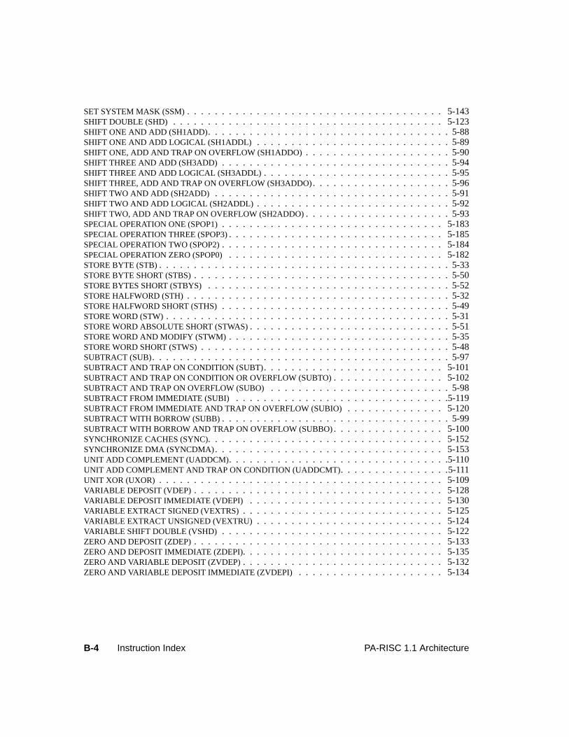
B-4 Instruction Index PA-RISC 1.1 Architecture
SET SYSTEM MASK (SSM) . . . . . . . . . . . . . . . . . . . . . . . . . . . . . . . . . . . . . 5-143SHIFT DOUBLE (SHD) . . . . . . . . . . . . . . . . . . . . . . . . . . . . . . . . . . . . . . . 5-123SHIFT ONE AND ADD (SH1ADD). . . . . . . . . . . . . . . . . . . . . . . . . . . . . . . . . . . 5-88SHIFT ONE AND ADD LOGICAL (SH1ADDL) . . . . . . . . . . . . . . . . . . . . . . . . . . . . 5-89SHIFT ONE, ADD AND TRAP ON OVERFLOW (SH1ADDO) . . . . . . . . . . . . . . . . . . . . . 5-90SHIFT THREE AND ADD (SH3ADD) . . . . . . . . . . . . . . . . . . . . . . . . . . . . . . . . . 5-94SHIFT THREE AND ADD LOGICAL (SH3ADDL) . . . . . . . . . . . . . . . . . . . . . . . . . . . 5-95SHIFT THREE, ADD AND TRAP ON OVERFLOW (SH3ADDO). . . . . . . . . . . . . . . . . . . . 5-96SHIFT TWO AND ADD (SH2ADD) . . . . . . . . . . . . . . . . . . . . . . . . . . . . . . . . . . 5-91SHIFT TWO AND ADD LOGICAL (SH2ADDL) . . . . . . . . . . . . . . . . . . . . . . . . . . . . 5-92SHIFT TWO, ADD AND TRAP ON OVERFLOW (SH2ADDO). . . . . . . . . . . . . . . . . . . . . 5-93SPECIAL OPERATION ONE (SPOP1) . . . . . . . . . . . . . . . . . . . . . . . . . . . . . . . . 5-183SPECIAL OPERATION THREE (SPOP3). . . . . . . . . . . . . . . . . . . . . . . . . . . . . . . 5-185SPECIAL OPERATION TWO (SPOP2) . . . . . . . . . . . . . . . . . . . . . . . . . . . . . . . . 5-184SPECIAL OPERATION ZERO (SPOP0) . . . . . . . . . . . . . . . . . . . . . . . . . . . . . . . 5-182STORE BYTE (STB). . . . . . . . . . . . . . . . . . . . . . . . . . . . . . . . . . . . . . . . . . 5-33STORE BYTE SHORT (STBS) . . . . . . . . . . . . . . . . . . . . . . . . . . . . . . . . . . . . . 5-50STORE BYTES SHORT (STBYS) . . . . . . . . . . . . . . . . . . . . . . . . . . . . . . . . . . . 5-52STORE HALFWORD (STH) . . . . . . . . . . . . . . . . . . . . . . . . . . . . . . . . . . . . . . 5-32STORE HALFWORD SHORT (STHS) . . . . . . . . . . . . . . . . . . . . . . . . . . . . . . . . . 5-49STORE WORD (STW) . . . . . . . . . . . . . . . . . . . . . . . . . . . . . . . . . . . . . . . . . 5-31STORE WORD ABSOLUTE SHORT (STWAS). . . . . . . . . . . . . . . . . . . . . . . . . . . . . 5-51STORE WORD AND MODIFY (STWM) . . . . . . . . . . . . . . . . . . . . . . . . . . . . . . . . 5-35STORE WORD SHORT (STWS) . . . . . . . . . . . . . . . . . . . . . . . . . . . . . . . . . . . . 5-48SUBTRACT (SUB). . . . . . . . . . . . . . . . . . . . . . . . . . . . . . . . . . . . . . . . . . .5-97SUBTRACT AND TRAP ON CONDITION (SUBT). . . . . . . . . . . . . . . . . . . . . . . . . . 5-101SUBTRACT AND TRAP ON CONDITION OR OVERFLOW (SUBTO). . . . . . . . . . . . . . . . 5-102SUBTRACT AND TRAP ON OVERFLOW (SUBO) . . . . . . . . . . . . . . . . . . . . . . . . . . 5-98SUBTRACT FROM IMMEDIATE (SUBI) . . . . . . . . . . . . . . . . . . . . . . . . . . . . . . .5-119SUBTRACT FROM IMMEDIATE AND TRAP ON OVERFLOW (SUBIO) . . . . . . . . . . . . . . 5-120SUBTRACT WITH BORROW (SUBB). . . . . . . . . . . . . . . . . . . . . . . . . . . . . . . . . 5-99SUBTRACT WITH BORROW AND TRAP ON OVERFLOW (SUBBO). . . . . . . . . . . . . . . . 5-100SYNCHRONIZE CACHES (SYNC). . . . . . . . . . . . . . . . . . . . . . . . . . . . . . . . . . 5-152SYNCHRONIZE DMA (SYNCDMA). . . . . . . . . . . . . . . . . . . . . . . . . . . . . . . . . 5-153UNIT ADD COMPLEMENT (UADDCM). . . . . . . . . . . . . . . . . . . . . . . . . . . . . . . .5-110UNIT ADD COMPLEMENT AND TRAP ON CONDITION (UADDCMT). . . . . . . . . . . . . . . .5-111UNIT XOR (UXOR) . . . . . . . . . . . . . . . . . . . . . . . . . . . . . . . . . . . . . . . . . 5-109VARIABLE DEPOSIT (VDEP) . . . . . . . . . . . . . . . . . . . . . . . . . . . . . . . . . . . . 5-128VARIABLE DEPOSIT IMMEDIATE (VDEPI) . . . . . . . . . . . . . . . . . . . . . . . . . . . . 5-130VARIABLE EXTRACT SIGNED (VEXTRS) . . . . . . . . . . . . . . . . . . . . . . . . . . . . . 5-125VARIABLE EXTRACT UNSIGNED (VEXTRU) . . . . . . . . . . . . . . . . . . . . . . . . . . . 5-124VARIABLE SHIFT DOUBLE (VSHD) . . . . . . . . . . . . . . . . . . . . . . . . . . . . . . . . 5-122ZERO AND DEPOSIT (ZDEP) . . . . . . . . . . . . . . . . . . . . . . . . . . . . . . . . . . . . 5-133ZERO AND DEPOSIT IMMEDIATE (ZDEPI). . . . . . . . . . . . . . . . . . . . . . . . . . . . . 5-135ZERO AND VARIABLE DEPOSIT (ZVDEP) . . . . . . . . . . . . . . . . . . . . . . . . . . . . . 5-132ZERO AND VARIABLE DEPOSIT IMMEDIATE (ZVDEPI) . . . . . . . . . . . . . . . . . . . . . 5-134
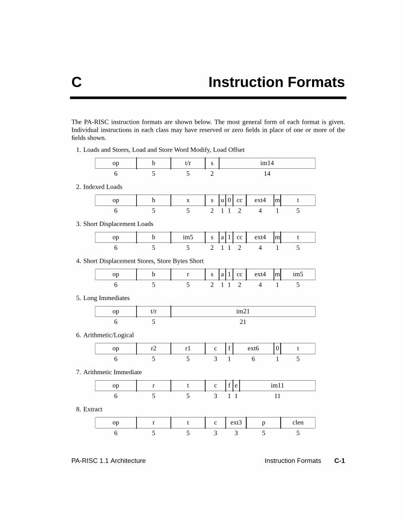
C-1PA-RISC 1.1 Architecture Instruction Formats
C Instruction Formats
The PA-RISC instruction formats are shown below. The most general form of each format is given.Individual instructions in each class may have reserved or zero fields in place of one or more of thefields shown.
1. Loads and Stores, Load and Store Word Modify, Load Offset
2. Indexed Loads
3. Short Displacement Loads
4. Short Displacement Stores, Store Bytes Short
5. Long Immediates
6. Arithmetic/Logical
7. Arithmetic Immediate
8. Extract
op b t/r s im14
6 5 5 2 14
op b x s u 0 cc ext4 m t
6 5 5 2 1 1 2 4 1 5
op b im5 s a 1 cc ext4 m t
6 5 5 2 1 1 2 4 1 5
op b r s a 1 cc ext4 m im5
6 5 5 2 1 1 2 4 1 5
op t/r im21
6 5 21
op r2 r1 c f ext6 0 t
6 5 5 3 1 6 1 5
op r t c f e im11
6 5 5 3 1 1 11
op r t c ext3 p clen
6 5 5 3 3 5 5
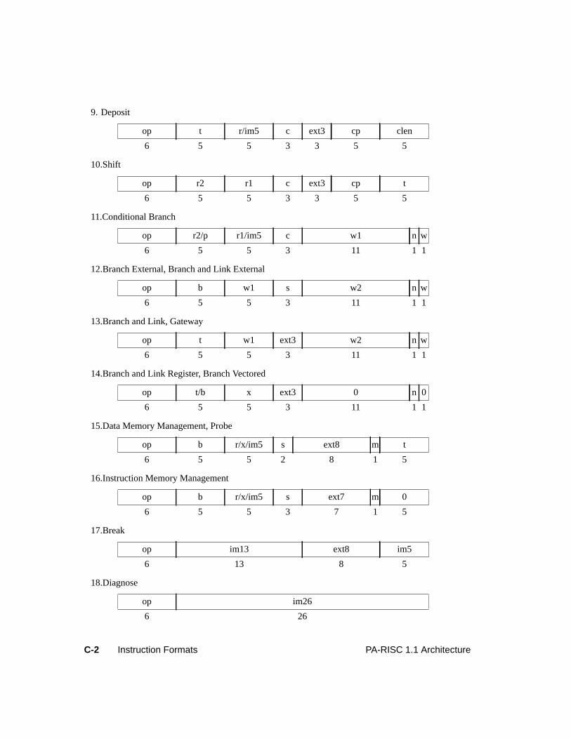
C-2 Instruction Formats PA-RISC 1.1 Architecture
9. Deposit
10.Shift
11.Conditional Branch
12.Branch External, Branch and Link External
13.Branch and Link, Gateway
14.Branch and Link Register, Branch Vectored
15.Data Memory Management, Probe
16.Instruction Memory Management
17.Break
18.Diagnose
op t r/im5 c ext3 cp clen
6 5 5 3 3 5 5
op r2 r1 c ext3 cp t
6 5 5 3 3 5 5
op r2/p r1/im5 c w1 n w
6 5 5 3 11 1 1
op b w1 s w2 n w
6 5 5 3 11 1 1
op t w1 ext3 w2 n w
6 5 5 3 11 1 1
op t/b x ext3 0 n 0
6 5 5 3 11 1 1
op b r/x/im5 s ext8 m t
6 5 5 2 8 1 5
op b r/x/im5 s ext7 m 0
6 5 5 3 7 1 5
op im13 ext8 im5
6 13 8 5
op im26
6 26
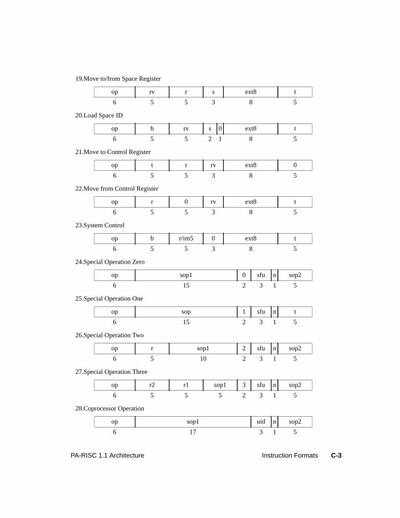
C-3PA-RISC 1.1 Architecture Instruction Formats
19.Move to/from Space Register
20.Load Space ID
21.Move to Control Register
22.Move from Control Register
23.System Control
24.Special Operation Zero
25.Special Operation One
26.Special Operation Two
27.Special Operation Three
28.Coprocessor Operation
op rv r s ext8 t
6 5 5 3 8 5
op b rv s 0 ext8 t
6 5 5 2 1 8 5
op t r rv ext8 0
6 5 5 3 8 5
op r 0 rv ext8 t
6 5 5 3 8 5
op b r/im5 0 ext8 t
6 5 5 3 8 5
op sop1 0 sfu n sop2
6 15 2 3 1 5
op sop 1 sfu n t
6 15 2 3 1 5
op r sop1 2 sfu n sop2
6 5 10 2 3 1 5
op r2 r1 sop1 3 sfu n sop2
6 5 5 5 2 3 1 5
op sop1 uid n sop2
6 17 3 1 5
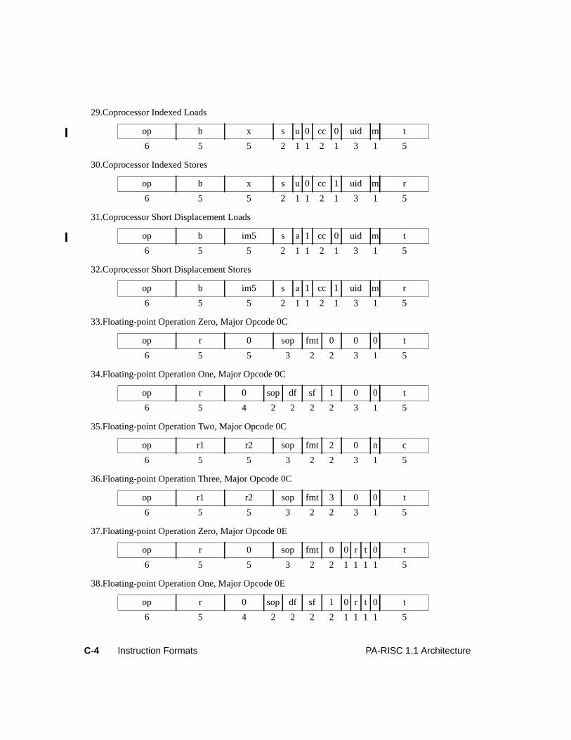
C-4 Instruction Formats PA-RISC 1.1 Architecture
29.Coprocessor Indexed Loads
30.Coprocessor Indexed Stores
31.Coprocessor Short Displacement Loads
32.Coprocessor Short Displacement Stores
33.Floating-point Operation Zero, Major Opcode 0C
34.Floating-point Operation One, Major Opcode 0C
35.Floating-point Operation Two, Major Opcode 0C
36.Floating-point Operation Three, Major Opcode 0C
37.Floating-point Operation Zero, Major Opcode 0E
38.Floating-point Operation One, Major Opcode 0E
op b x s u 0 cc 0 uid m t
6 5 5 2 1 1 2 1 3 1 5
op b x s u 0 cc 1 uid m r
6 5 5 2 1 1 2 1 3 1 5
op b im5 s a 1 cc 0 uid m t
6 5 5 2 1 1 2 1 3 1 5
op b im5 s a 1 cc 1 uid m r
6 5 5 2 1 1 2 1 3 1 5
op r 0 sop fmt 0 0 0 t
6 5 5 3 2 2 3 1 5
op r 0 sop df sf 1 0 0 t
6 5 4 2 2 2 2 3 1 5
op r1 r2 sop fmt 2 0 n c
6 5 5 3 2 2 3 1 5
op r1 r2 sop fmt 3 0 0 t
6 5 5 3 2 2 3 1 5
op r 0 sop fmt 0 0 r t 0 t
6 5 5 3 2 2 1 1 1 1 5
op r 0 sop df sf 1 0 r t 0 t
6 5 4 2 2 2 2 1 1 1 1 5
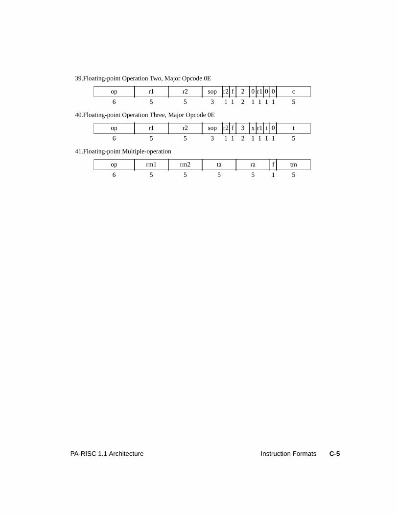
C-5PA-RISC 1.1 Architecture Instruction Formats
39.Floating-point Operation Two, Major Opcode 0E
40.Floating-point Operation Three, Major Opcode 0E
41.Floating-point Multiple-operation
op r1 r2 sop r2 f 2 0 r1 0 0 c
6 5 5 3 1 1 2 1 1 1 1 5
op r1 r2 sop r2 f 3 x r1 t 0 t
6 5 5 3 1 1 2 1 1 1 1 5
op rm1 rm2 ta ra f tm
6 5 5 5 5 1 5
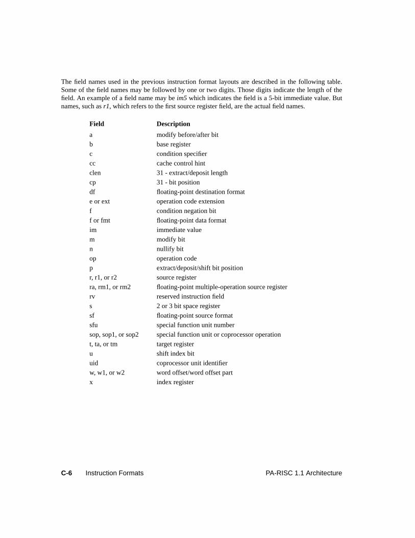
C-6 Instruction Formats PA-RISC 1.1 Architecture
The field names used in the previous instruction format layouts are described in the following table.Some of the field names may be followed by one or two digits. Those digits indicate the length of thefield. An example of a field name may beim5 which indicates the field is a 5-bit immediate value. Butnames, such asr1, which refers to the first source register field, are the actual field names.
Field Description
a modify before/after bit
b base register
c condition specifier
cc cache control hint
clen 31 - extract/deposit length
cp 31 - bit position
df floating-point destination format
e or ext operation code extension
f condition negation bit
f or fmt floating-point data format
im immediate value
m modify bit
n nullify bit
op operation code
p extract/deposit/shift bit position
r, r1, or r2 source register
ra, rm1, or rm2 floating-point multiple-operation source register
rv reserved instruction field
s 2 or 3 bit space register
sf floating-point source format
sfu special function unit number
sop, sop1, or sop2 special function unit or coprocessor operation
t, ta, or tm target register
u shift index bit
uid coprocessor unit identifier
w, w1, or w2 word offset/word offset part
x index register
D-1PA-RISC 1.1 Architecture Operation Codes
D Operation Codes
Major Opcode AssignmentsThe major opcode assignments are listed in Table D-1. Instructions are shown in uppercase. Instructionclasses are capitalized. Extensions of the major opcodes can be found in the tables indicated, whereapplicable. In the following discussions of opcode extensions the major opcode class names are shownin parentheses.
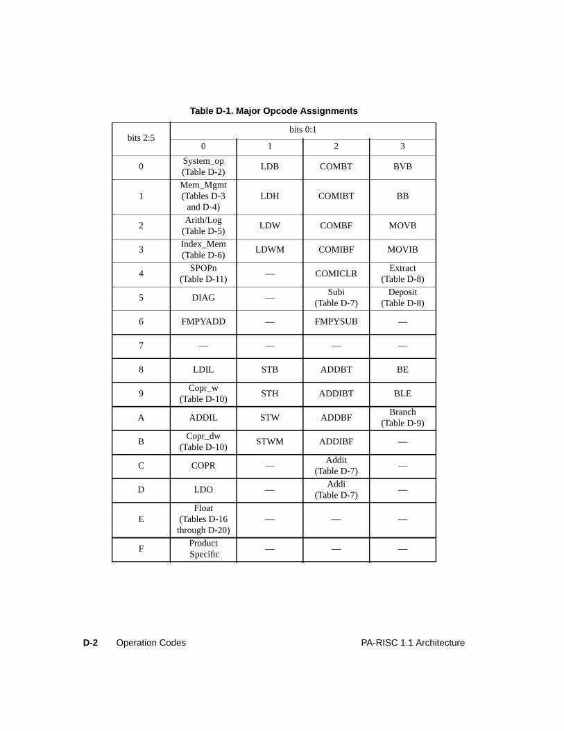
D-2 Operation Codes PA-RISC 1.1 Architecture
Table D-1. Major Opcode Assignments
bits 2:5bits 0:1
0 1 2 3
0System_op(Table D-2)
LDB COMBT BVB
1Mem_Mgmt(Tables D-3
and D-4)LDH COMIBT BB
2Arith/Log
(Table D-5)LDW COMBF MOVB
3Index_Mem(Table D-6)
LDWM COMIBF MOVIB
4SPOPn
(Table D-11)— COMICLR
Extract(Table D-8)
5 DIAG —Subi
(Table D-7)Deposit
(Table D-8)
6 FMPYADD — FMPYSUB —
7 — — — —
8 LDIL STB ADDBT BE
9Copr_w
(Table D-10)STH ADDIBT BLE
A ADDIL STW ADDBFBranch
(Table D-9)
BCopr_dw
(Table D-10)STWM ADDIBF —
C COPR —Addit
(Table D-7)—
D LDO —Addi
(Table D-7)—
EFloat
(Tables D-16through D-20)
— — —
FProduct Specific
— — —
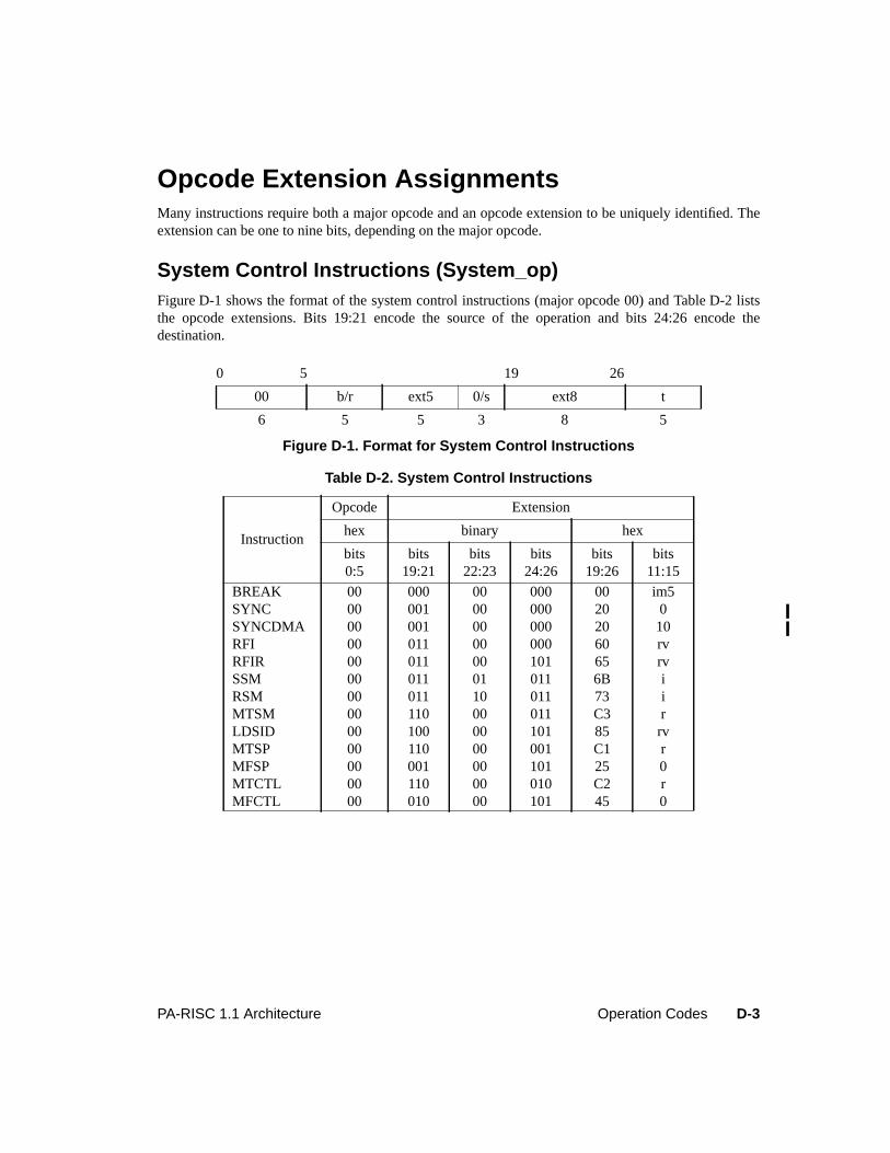
D-3PA-RISC 1.1 Architecture Operation Codes
Opcode Extension AssignmentsMany instructions require both a major opcode and an opcode extension to be uniquely identified. Theextension can be one to nine bits, depending on the major opcode.
System Control Instructions (System_op)Figure D-1 shows the format of the system control instructions (major opcode 00) and Table D-2 liststhe opcode extensions. Bits 19:21 encode the source of the operation and bits 24:26 encode thedestination.
0 5 19 26
00 b/r ext5 0/s ext8 t
6 5 5 3 8 5
Figure D-1. Format for System Control Instructions
Table D-2. System Control Instructions
Instruction
Opcode Extension
hex binary hex
bits0:5
bits19:21
bits22:23
bits24:26
bits19:26
bits11:15
BREAK 00 000 00 000 00 im5SYNC 00 001 00 000 20 0SYNCDMA 00 001 00 000 20 10RFI 00 011 00 000 60 rvRFIR 00 011 00 101 65 rvSSM 00 011 01 011 6B iRSM 00 011 10 011 73 iMTSM 00 110 00 011 C3 rLDSID 00 100 00 101 85 rvMTSP 00 110 00 001 C1 rMFSP 00 001 00 101 25 0MTCTL 00 110 00 010 C2 rMFCTL 00 010 00 101 45 0
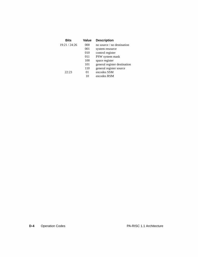
D-4 Operation Codes PA-RISC 1.1 Architecture
Bits Value Description19:21 / 24:26 000 no source / no destination
001 system resource010 control register011 PSW system mask100 space register101 general register destination110 general register source
22:23 01 encodes SSM10 encodes RSM
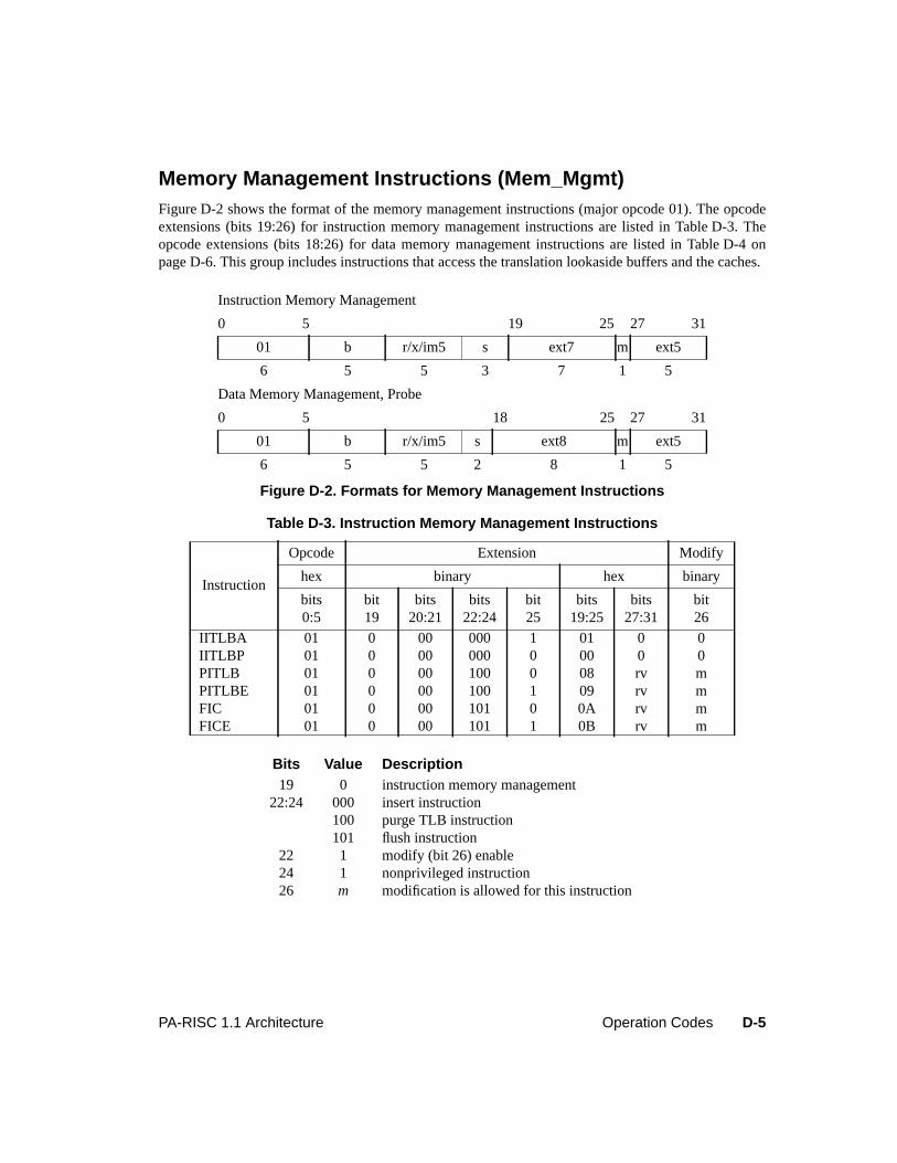
D-5PA-RISC 1.1 Architecture Operation Codes
Memory Management Instructions (Mem_Mgmt)Figure D-2 shows the format of the memory management instructions (major opcode 01). The opcodeextensions (bits 19:26) for instruction memory management instructions are listed in Table D-3. Theopcode extensions (bits 18:26) for data memory management instructions are listed in Table D-4 onpage D-6. This group includes instructions that access the translation lookaside buffers and the caches.
Instruction Memory Management
0 5 19 25 27 31
01 b r/x/im5 s ext7 m ext5
6 5 5 3 7 1 5
Data Memory Management, Probe
0 5 18 25 27 31
01 b r/x/im5 s ext8 m ext5
6 5 5 2 8 1 5
Figure D-2. Formats for Memory Management Instructions
Table D-3. Instruction Memory Management Instructions
Instruction
Opcode Extension Modify
hex binary hex binary
bits0:5
bit19
bits20:21
bits22:24
bit25
bits19:25
bits27:31
bit26
IITLBA 01 0 00 000 1 01 0 0IITLBP 01 0 00 000 0 00 0 0PITLB 01 0 00 100 0 08 rv mPITLBE 01 0 00 100 1 09 rv mFIC 01 0 00 101 0 0A rv mFICE 01 0 00 101 1 0B rv m
Bits Value Description19 0 instruction memory management
22:24 000 insert instruction100 purge TLB instruction101 flush instruction
22 1 modify (bit 26) enable24 1 nonprivileged instruction26 m modification is allowed for this instruction
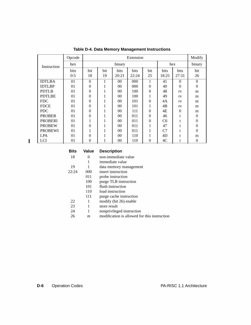
D-6 Operation Codes PA-RISC 1.1 Architecture
Table D-4. Data Memory Management Instructions
Instruction
Opcode Extension Modify
hex binary hex binary
bits0:5
bit18
bit19
bits20:21
bits22:24
bit25
bits18:25
bits27:31
bit26
IDTLBA 01 0 1 00 000 1 41 0 0IDTLBP 01 0 1 00 000 0 40 0 0PDTLB 01 0 1 00 100 0 48 rv mPDTLBE 01 0 1 00 100 1 49 rv mFDC 01 0 1 00 101 0 4A rv mFDCE 01 0 1 00 101 1 4B rv mPDC 01 0 1 00 111 0 4E 0 mPROBER 01 0 1 00 011 0 46 t 0PROBERI 01 1 1 00 011 0 C6 t 0PROBEW 01 0 1 00 011 1 47 t 0PROBEWI 01 1 1 00 011 1 C7 t 0LPA 01 0 1 00 110 1 4D t mLCI 01 0 1 00 110 0 4C t 0
Bits Value Description18 0 non-immediate value
1 immediate value19 1 data memory management
22:24 000 insert instruction011 probe instruction100 purge TLB instruction101 flush instruction110 load instruction111 purge cache instruction
22 1 modify (bit 26) enable23 1 store result24 1 nonprivileged instruction26 m modification is allowed for this instruction
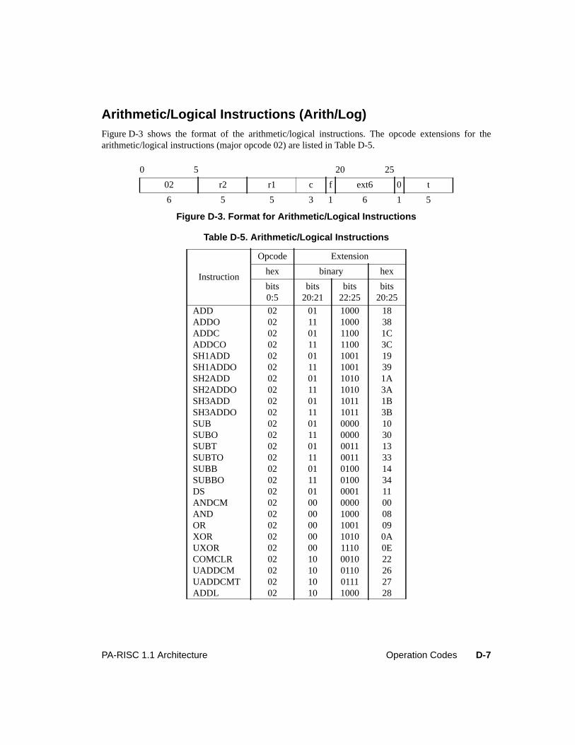
D-7PA-RISC 1.1 Architecture Operation Codes
Arithmetic/Logical Instructions (Arith/Log)Figure D-3 shows the format of the arithmetic/logical instructions. The opcode extensions for thearithmetic/logical instructions (major opcode 02) are listed in Table D-5.
0 5 20 25
02 r2 r1 c f ext6 0 t
6 5 5 3 1 6 1 5
Figure D-3. Format for Arithmetic/Logical Instructions
Table D-5. Arithmetic/Logical Instructions
Instruction
Opcode Extension
hex binary hex
bits0:5
bits20:21
bits22:25
bits20:25
ADD 02 01 1000 18ADDO 02 11 1000 38ADDC 02 01 1100 1CADDCO 02 11 1100 3CSH1ADD 02 01 1001 19SH1ADDO 02 11 1001 39SH2ADD 02 01 1010 1ASH2ADDO 02 11 1010 3ASH3ADD 02 01 1011 1BSH3ADDO 02 11 1011 3BSUB 02 01 0000 10SUBO 02 11 0000 30SUBT 02 01 0011 13SUBTO 02 11 0011 33SUBB 02 01 0100 14SUBBO 02 11 0100 34DS 02 01 0001 11ANDCM 02 00 0000 00AND 02 00 1000 08OR 02 00 1001 09XOR 02 00 1010 0AUXOR 02 00 1110 0ECOMCLR 02 10 0010 22UADDCM 02 10 0110 26UADDCMT 02 10 0111 27ADDL 02 10 1000 28
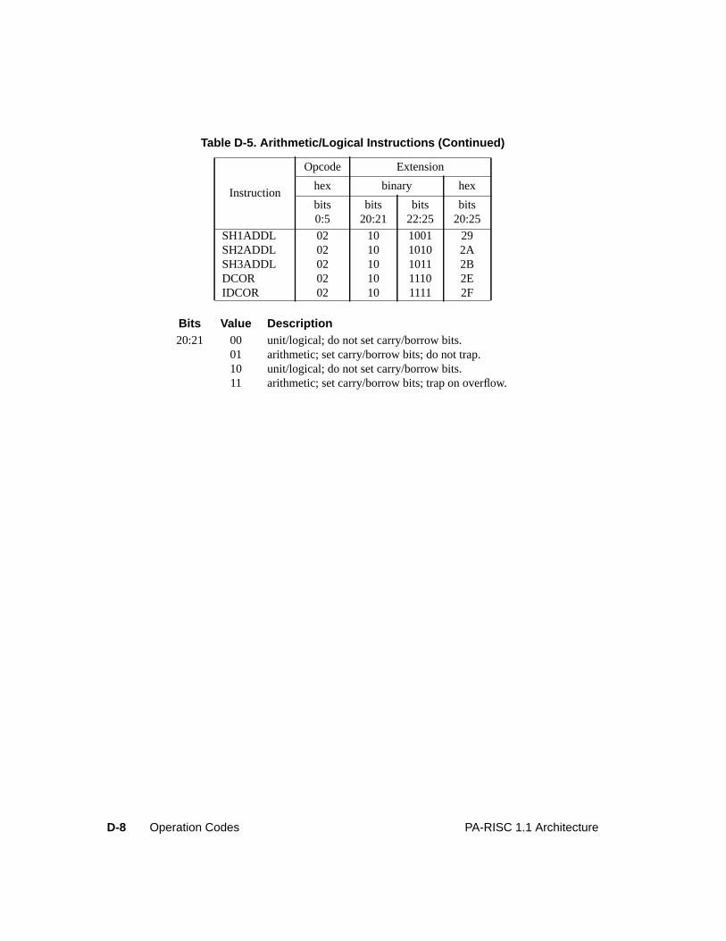
D-8 Operation Codes PA-RISC 1.1 Architecture
SH1ADDL 02 10 1001 29SH2ADDL 02 10 1010 2ASH3ADDL 02 10 1011 2BDCOR 02 10 1110 2EIDCOR 02 10 1111 2F
Bits Value Description20:21 00 unit/logical; do not set carry/borrow bits.
01 arithmetic; set carry/borrow bits; do not trap.10 unit/logical; do not set carry/borrow bits.11 arithmetic; set carry/borrow bits; trap on overflow.
Table D-5. Arithmetic/Logical Instructions (Continued)
Instruction
Opcode Extension
hex binary hex
bits0:5
bits20:21
bits22:25
bits20:25
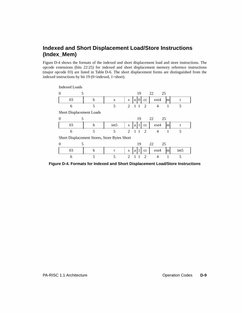
D-9PA-RISC 1.1 Architecture Operation Codes
Indexed and Short Displacement Load/Store Instructions(Index_Mem)Figure D-4 shows the formats of the indexed and short displacement load and store instructions. Theopcode extensions (bits 22:25) for indexed and short displacement memory reference instructions(major opcode 03) are listed in Table D-6. The short displacement forms are distinguished from theindexed instructions by bit 19 (0=indexed, 1=short).
Indexed Loads
0 5 19 22 25
03 b x s u 0 cc ext4 m t
6 5 5 2 1 1 2 4 1 5
Short Displacement Loads
0 5 19 22 25
03 b im5 s a 1 cc ext4 m t
6 5 5 2 1 1 2 4 1 5
Short Displacement Stores, Store Bytes Short
0 5 19 22 25
03 b r s a 1 cc ext4 m im5
6 5 5 2 1 1 2 4 1 5
Figure D-4. Formats for Indexed and Short Displacement Load/Store Instructions
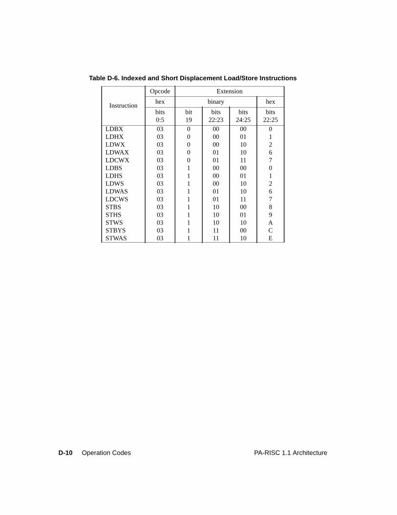
D-10 Operation Codes PA-RISC 1.1 Architecture
Table D-6. Indexed and Short Displacement Load/Store Instructions
Instruction
Opcode Extension
hex binary hex
bits0:5
bit19
bits22:23
bits24:25
bits22:25
LDBX 03 0 00 00 0LDHX 03 0 00 01 1LDWX 03 0 00 10 2LDWAX 03 0 01 10 6LDCWX 03 0 01 11 7LDBS 03 1 00 00 0LDHS 03 1 00 01 1LDWS 03 1 00 10 2LDWAS 03 1 01 10 6LDCWS 03 1 01 11 7STBS 03 1 10 00 8STHS 03 1 10 01 9STWS 03 1 10 10 ASTBYS 03 1 11 00 CSTWAS 03 1 11 10 E
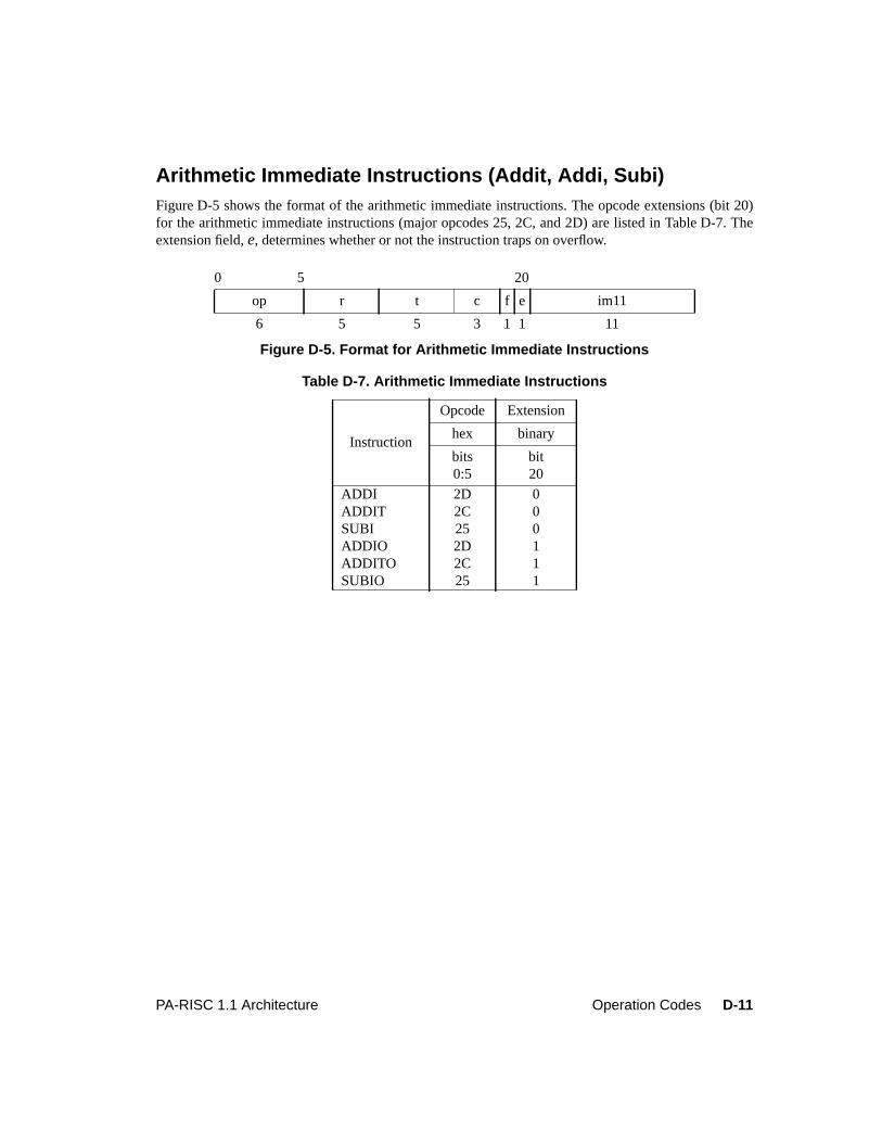
D-11PA-RISC 1.1 Architecture Operation Codes
Arithmetic Immediate Instructions (Addit, Addi, Subi)Figure D-5 shows the format of the arithmetic immediate instructions. The opcode extensions (bit 20)for the arithmetic immediate instructions (major opcodes 25, 2C, and 2D) are listed in Table D-7. Theextension field,e, determines whether or not the instruction traps on overflow.
0 5 20
op r t c f e im11
6 5 5 3 1 1 11
Figure D-5. Format for Arithmetic Immediate Instructions
Table D-7. Arithmetic Immediate Instructions
Instruction
Opcode Extension
hex binary
bits0:5
bit20
ADDI 2D 0ADDIT 2C 0SUBI 25 0ADDIO 2D 1ADDITO 2C 1SUBIO 25 1
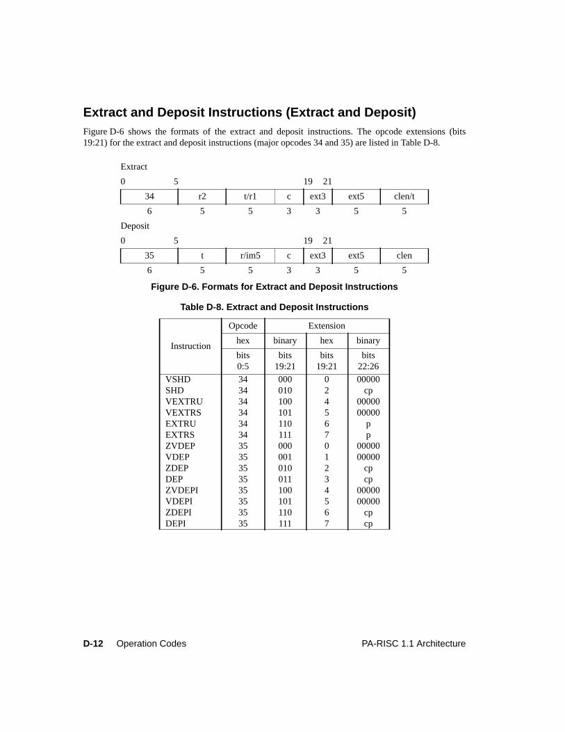
D-12 Operation Codes PA-RISC 1.1 Architecture
Extract and Deposit Instructions (Extract and Deposit)Figure D-6 shows the formats of the extract and deposit instructions. The opcode extensions (bits19:21) for the extract and deposit instructions (major opcodes 34 and 35) are listed in Table D-8.
Extract
0 5 19 21
34 r2 t/r1 c ext3 ext5 clen/t
6 5 5 3 3 5 5
Deposit
0 5 19 21
35 t r/im5 c ext3 ext5 clen
6 5 5 3 3 5 5
Figure D-6. Formats for Extract and Deposit Instructions
Table D-8. Extract and Deposit Instructions
Instruction
Opcode Extension
hex binary hex binary
bits0:5
bits19:21
bits19:21
bits22:26
VSHD 34 000 0 00000SHD 34 010 2 cpVEXTRU 34 100 4 00000VEXTRS 34 101 5 00000EXTRU 34 110 6 pEXTRS 34 111 7 pZVDEP 35 000 0 00000VDEP 35 001 1 00000ZDEP 35 010 2 cpDEP 35 011 3 cpZVDEPI 35 100 4 00000VDEPI 35 101 5 00000ZDEPI 35 110 6 cpDEPI 35 111 7 cp
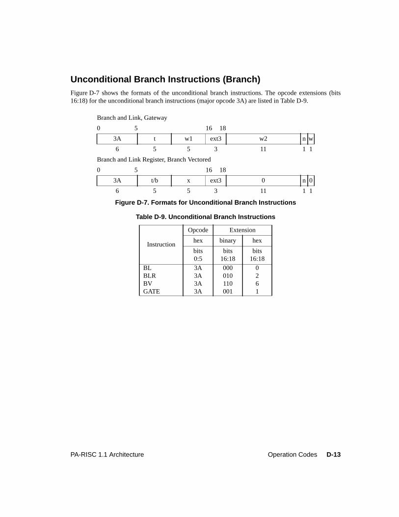
D-13PA-RISC 1.1 Architecture Operation Codes
Unconditional Branch Instructions (Branch)Figure D-7 shows the formats of the unconditional branch instructions. The opcode extensions (bits16:18) for the unconditional branch instructions (major opcode 3A) are listed in Table D-9.
Branch and Link, Gateway
0 5 16 18
3A t w1 ext3 w2 n w
6 5 5 3 11 1 1
Branch and Link Register, Branch Vectored
0 5 16 18
3A t/b x ext3 0 n 0
6 5 5 3 11 1 1
Figure D-7. Formats for Unconditional Branch Instructions
Table D-9. Unconditional Branch Instructions
Instruction
Opcode Extension
hex binary hex
bits0:5
bits16:18
bits16:18
BL 3A 000 0BLR 3A 010 2BV 3A 110 6GATE 3A 001 1
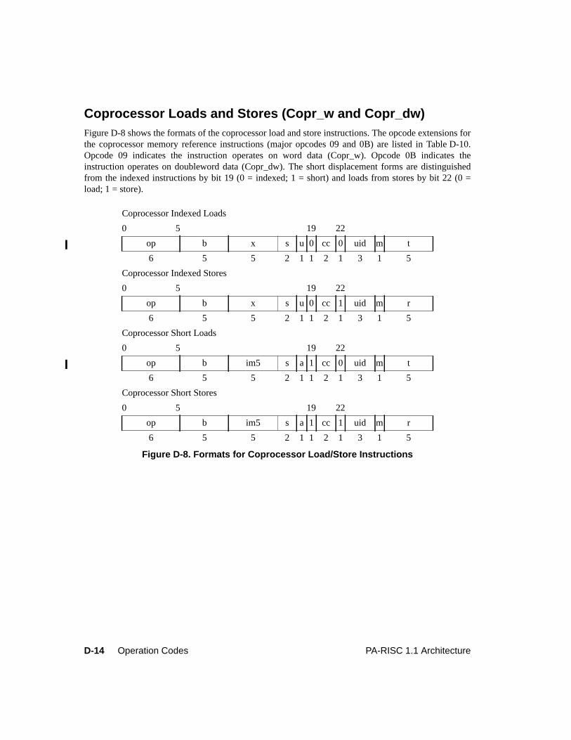
D-14 Operation Codes PA-RISC 1.1 Architecture
Coprocessor Loads and Stores (Copr_w and Copr_dw)Figure D-8 shows the formats of the coprocessor load and store instructions. The opcode extensions forthe coprocessor memory reference instructions (major opcodes 09 and 0B) are listed in Table D-10.Opcode 09 indicates the instruction operates on word data (Copr_w). Opcode 0B indicates theinstruction operates on doubleword data (Copr_dw). The short displacement forms are distinguishedfrom the indexed instructions by bit 19 (0 = indexed; 1 = short) and loads from stores by bit 22 (0 =load; 1 = store).
Coprocessor Indexed Loads
0 5 19 22
op b x s u 0 cc 0 uid m t
6 5 5 2 1 1 2 1 3 1 5
Coprocessor Indexed Stores
0 5 19 22
op b x s u 0 cc 1 uid m r
6 5 5 2 1 1 2 1 3 1 5
Coprocessor Short Loads
0 5 19 22
op b im5 s a 1 cc 0 uid m t
6 5 5 2 1 1 2 1 3 1 5
Coprocessor Short Stores
0 5 19 22
op b im5 s a 1 cc 1 uid m r
6 5 5 2 1 1 2 1 3 1 5
Figure D-8. Formats for Coprocessor Load/Store Instructions
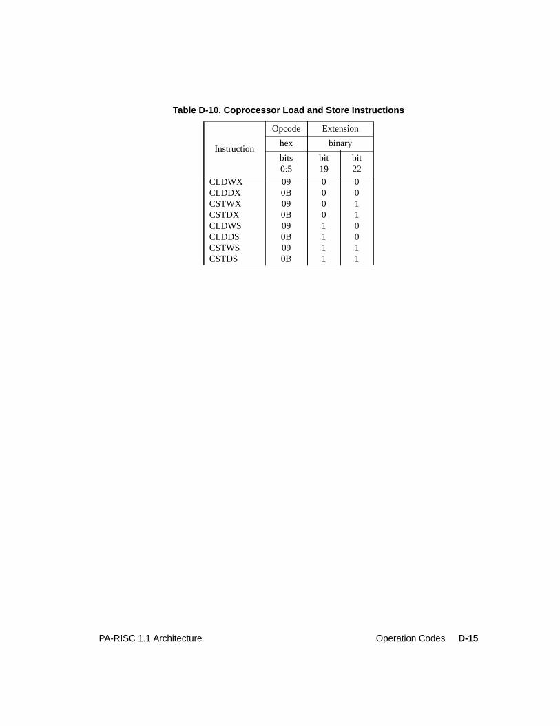
D-15PA-RISC 1.1 Architecture Operation Codes
Table D-10. Coprocessor Load and Store Instructions
Instruction
Opcode Extension
hex binary
bits0:5
bit19
bit22
CLDWX 09 0 0CLDDX 0B 0 0CSTWX 09 0 1CSTDX 0B 0 1CLDWS 09 1 0CLDDS 0B 1 0CSTWS 09 1 1CSTDS 0B 1 1
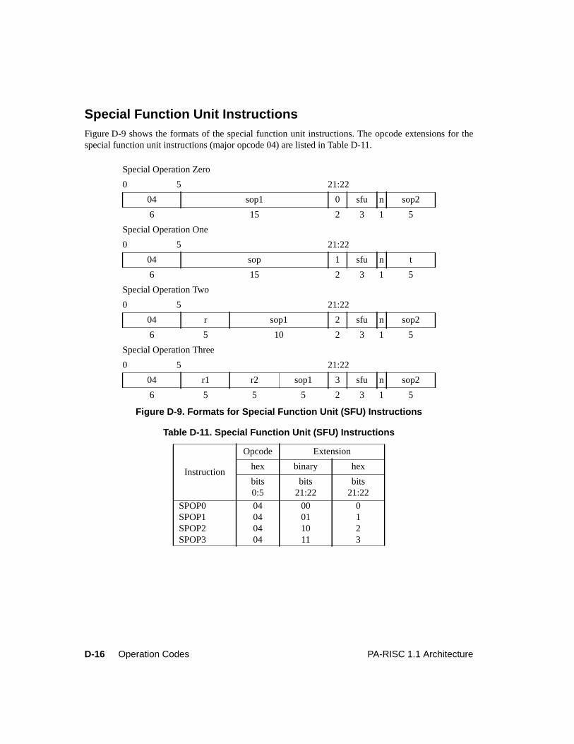
D-16 Operation Codes PA-RISC 1.1 Architecture
Special Function Unit InstructionsFigure D-9 shows the formats of the special function unit instructions. The opcode extensions for thespecial function unit instructions (major opcode 04) are listed in Table D-11.
Special Operation Zero
0 5 21:22
04 sop1 0 sfu n sop2
6 15 2 3 1 5
Special Operation One
0 5 21:22
04 sop 1 sfu n t
6 15 2 3 1 5
Special Operation Two
0 5 21:22
04 r sop1 2 sfu n sop2
6 5 10 2 3 1 5
Special Operation Three
0 5 21:22
04 r1 r2 sop1 3 sfu n sop2
6 5 5 5 2 3 1 5
Figure D-9. Formats for Special Function Unit (SFU) Instructions
Table D-11. Special Function Unit (SFU) Instructions
Instruction
Opcode Extension
hex binary hex
bits0:5
bits21:22
bits21:22
SPOP0 04 00 0SPOP1 04 01 1SPOP2 04 10 2SPOP3 04 11 3
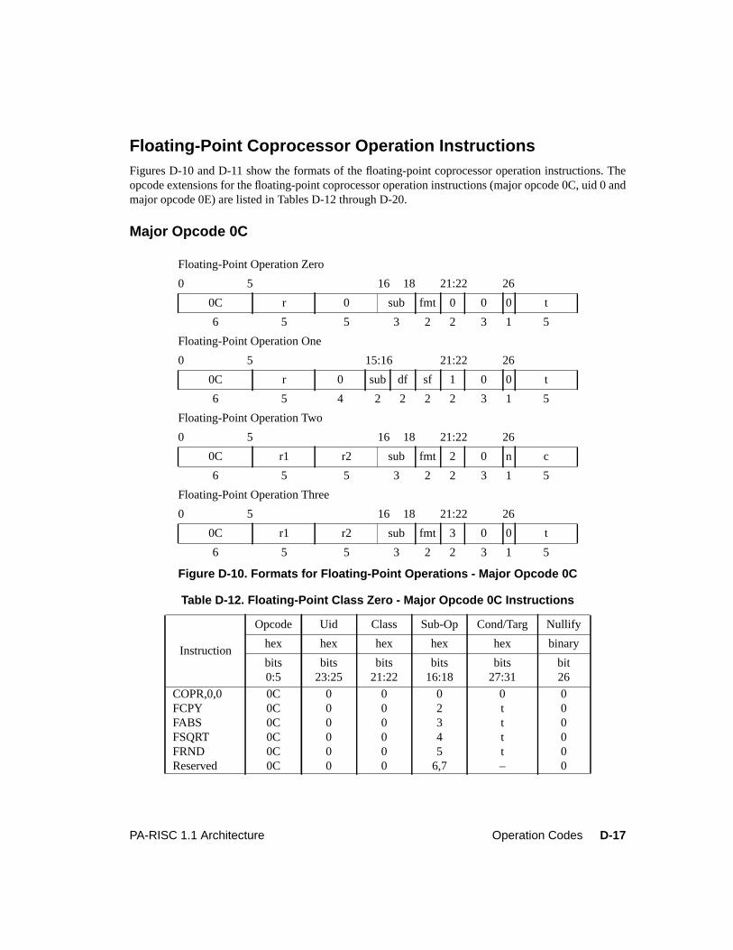
D-17PA-RISC 1.1 Architecture Operation Codes
Floating-Point Coprocessor Operation InstructionsFigures D-10 and D-11 show the formats of the floating-point coprocessor operation instructions. Theopcode extensions for the floating-point coprocessor operation instructions (major opcode 0C, uid 0 andmajor opcode 0E) are listed in Tables D-12 through D-20.
Major Opcode 0C
Floating-Point Operation Zero
0 5 16 18 21:22 26
0C r 0 sub fmt 0 0 0 t
6 5 5 3 2 2 3 1 5
Floating-Point Operation One
0 5 15:16 21:22 26
0C r 0 sub df sf 1 0 0 t
6 5 4 2 2 2 2 3 1 5
Floating-Point Operation Two
0 5 16 18 21:22 26
0C r1 r2 sub fmt 2 0 n c
6 5 5 3 2 2 3 1 5
Floating-Point Operation Three
0 5 16 18 21:22 26
0C r1 r2 sub fmt 3 0 0 t
6 5 5 3 2 2 3 1 5
Figure D-10. Formats for Floating-Point Operations - Major Opcode 0C
Table D-12. Floating-Point Class Zero - Major Opcode 0C Instructions
Instruction
Opcode Uid Class Sub-Op Cond/Targ Nullify
hex hex hex hex hex binary
bits0:5
bits23:25
bits21:22
bits16:18
bits27:31
bit26
COPR,0,0 0C 0 0 0 0 0FCPY 0C 0 0 2 t 0FABS 0C 0 0 3 t 0FSQRT 0C 0 0 4 t 0FRND 0C 0 0 5 t 0Reserved 0C 0 0 6,7 – 0
D-18 Operation Codes PA-RISC 1.1 Architecture
Table D-13. Floating-Point Class One - Major Opcode 0C Instructions
Instruction
Opcode Uid Class Sub-Op Cond/Targ Nullify
hex hex hex hex hex binary
bits0:5
bits23:25
bits21:22
bits15:16
bits27:31
bit26
FCNVFF 0C 0 1 0 t 0FCNVXF 0C 0 1 1 t 0FCNVFX 0C 0 1 2 t 0FCNVFXT 0C 0 1 3 t 0
Table D-14. Floating-Point Class Two - Major Opcode 0C Instructions
Instruction
Opcode Uid Class Sub-Op Cond/Targ Nullify
hex hex hex hex hex binary
bits0:5
bits23:25
bits21:22
bits16:18
bits27:31
bit26
FCMP 0C 0 2 0 c 0FTEST 0C 0 2 1 c 1Undefined 0C 0 2 2-7 – 0
Table D-15. Floating-Point Class Three - Major Opcode 0C Instructions
Instruction
Opcode Uid Class Sub-Op Cond/Targ Nullify
hex hex hex hex hex binary
bits0:5
bits23:25
bits21:22
bits16:18
bits27:31
bit26
FADD 0C 0 3 0 t 0FSUB 0C 0 3 1 t 0FMPY 0C 0 3 2 t 0FDIV 0C 0 3 3 t 0Reserved 0C 0 3 4-6 – 0Undefined 0C 0 3 7 – 0
D-19PA-RISC 1.1 Architecture Operation Codes
Major Opcode 0E (Float)
Floating-Point Operation Zero
0 5 16 18 21:22 26
0E r 0 sub fmt 0 0 r t 0 t
6 5 5 3 2 2 1 1 1 1 5
Floating-Point Operation One
0 5 15:16 21:22 26
0E r 0 sub df sf 1 0 r t 0 t
6 5 4 2 2 2 2 1 1 1 1 5
Floating-Point Operation Two
0 5 16 18 21:22 26
0E r1 r2 sub r2 f 2 0 r1 0 0 c
6 5 5 3 1 1 2 1 1 1 1 5
Floating-Point Operation Three
0 5 16 18 21:22 26
0E r1 r2 sub r2 f 3 0 r1 t 0 t
6 5 5 3 1 1 2 1 1 1 1 5
Fixed-Point Operation Three
0 5 16 18 21:22 26
0E r1 r2 sub r2 m 3 1 r1 t 0 t
6 5 5 3 1 1 2 1 1 1 1 5
Figure D-11. Formats for Floating-Point Operations - Major Opcode 0E
Table D-16. Floating-Point Class Zero - Major Opcode 0E Instructions
Instruction
Opcode Class Sub-Op Fixed Nullify Format Cond/Targ
hex hex hex binary binary hex hex
bits0:5
bits21:22
bits16:18
bit23
bit26
bits19:20
bits25,27:31
Undefined 0E 0 0,1 0 0 – –FCPY 0E 0 2 0 0 fmt tFABS 0E 0 3 0 0 fmt tFSQRT 0E 0 4 0 0 fmt tFRND 0E 0 5 0 0 fmt tReserved 0E 0 6,7 0 0 – –
D-20 Operation Codes PA-RISC 1.1 Architecture
Table D-17. Floating-Point Class One - Major Opcode 0E Instructions
Instruction
Opcode Class Sub-Op Fixed Nullify Format Cond/Targ
hex hex hex binary binary hex hex
bits0:5
bits21:22
bits15:16
bit23
bit26
bits17:20
bits25,27:31
FCNVFF 0E 1 0 0 0 df,sf tFCNVXF 0E 1 1 0 0 df,sf tFCNVFX 0E 1 2 0 0 df,sf tFCNVFXT 0E 1 3 0 0 df,sf t
Table D-18. Floating-Point Class Two - Major Opcode 0E Instructions
Instruction
Opcode Class Sub-Op Fixed Nullify Format Cond/Targ
hex hex hex binary binary binary hex
bits0:5
bits21:22
bits16:18
bit23
bit26
bit20
bits25,27:31
FCMP 0E 2 0 0 0 f 0,cUndefined 0E 2 1-7 – 0 – –
Table D-19. Floating-Point Class Three - Major Opcode 0E Instructions
Instruction
Opcode Class Sub-Op Fixed Nullify Format Cond/Targ
hex hex hex binary binary binary hex
bits0:5
bits21:22
bits16:18
bit23
bit26
bit20
bits25,27:31
FADD 0E 3 0 0 0 f tFSUB 0E 3 1 0 0 f tFMPY 0E 3 2 0 0 f tFDIV 0E 3 3 0 0 f tUndefined 0E 3 4 0 0 – –Reserved 0E 3 5-6 0 0 – –Undefined 0E 3 7 0 0 – –
Table D-20. Fixed-Point Class Three - Major Opcode 0E Instructions
Instruction
Opcode Class Sub-Op Fixed Nullify Format Cond/Targ
hex hex hex binary binary binary hex
bits0:5
bits21:22
bits16:18
bit23
bit26
bit20
bits25,27:31
XMPYU 0E 3 2 1 0 0 t
D-21PA-RISC 1.1 Architecture Operation Codes
Performance Monitor Coprocessor InstructionsFigure D-12 shows the format of the performance monitor coprocessor operation instructions. Theopcode extensions for the performance monitor coprocessor instructions (major opcode 0C, uid 2) arelisted in Table D-21.
0 5 18 22 26
0C rv sub 2 n rv
6 12 5 3 1 5
Figure D-12. Format for Performance Monitor Coprocessor Instructions
Table D-21. Performance Monitor Coprocessor Instructions
Instruction
Opcode Uid Sub-Op Nullify
hex hex hex binary
bits0:5
bits23:25
bits18:22
bit26
PMDIS 0C 2 1 0PMENB 0C 2 3 0Undefined 0C 2 0,2,4..1F –
D-22 Operation Codes PA-RISC 1.1 Architecture
Debug SFU InstructionsFigure D-13 shows the format of the debug special function unit instructions. The opcode extensions forthe debug SFU instructions (major opcode 04, uid 1) are listed in Table D-22.
Debug Operation One
0 5 18 20 23 25
04 r rv sub 1 1 0 t
6 5 7 3 2 3 1 5
Debug Operation Two
0 5 18 20 23 25
04 r rv sub 2 1 0 t
6 5 7 3 2 3 1 5
Figure D-13. Debug SFU Instruction Formats
Table D-22. Debug SFU Instructions
Instruction
Opcode Uid Class Sub-Op
hex hex hex hex
bits0:5
bits23:25
bits21:22
bits18:20
MTDBAO 04 1 1 4MTDBAM 04 1 1 5MTIBAO 04 1 1 6MTIBAM 04 1 1 7DEBUGID 04 1 2 0MFDBAO 04 1 2 4MFDBAM 04 1 2 5MFIBAO 04 1 2 6MFIBAM 04 1 2 7
E-1PA-RISC 1.1 Architecture Level 0 Summary
E Level 0 Summary
The following list summarizes the differences between Level 0 and non-Level 0 processors.
• Only absolute memory addressing is supported; virtual memory is not supported, and so spaceidentifiers are not used and Space Registers are nonexistent registers.
• PID Registers (CRs 8, 9, 12, and 13), IIASQ (CR 17), and ISR (CR 20) are nonexistent registers.
• The X, C, P, and D bits of the PSW and the IPSW are nonexistent bits.
• There are only two distinct privilege levels - 0 and non-zero; privilege levels 1, 2, and 3 areequivalent.
• There are no TLBs.
• The s-fields of all instructions are ignored.
• The debug SFU, PSW G-bit, PSW Y-bit, PSW Z-bit, data debug trap, and instruction debug trap aredefined only for Level 0 systems.
• The following TLB related instructions are executed as null instructions at all privilege levels:
• The following interruptions do not occur.
PURGE DATA TLB (PDTLB)
PURGE INSTRUCTION TLB (PITLB)
PURGE DATA TLB ENTRY (PDTLBE)
PURGE INSTRUCTION TLB ENTRY (PITLBE)
INSERT DATA TLB ADDRESS (IDTLBA)
INSERT INSTRUCTION TLB ADDRESS (IITLBA)
INSERT DATA TLB PROTECTION (IDTLBP)
INSERT INSTRUCTION TLB PROTECTION (IITLBP)
Interruption Name Number
Instruction TLB miss fault/instruction page fault 6
Instruction memory protection trap 7
Data TLB miss fault/Data page fault 15
Non-access instruction TLB miss fault 16
Non-access data TLB miss fault/non-access data page fault 17
Data memory access rights trap 26
Data memory protection ID trap 27
Unaligned data reference trap 28
Data memory protection trap/Unaligned data reference trap 18
E-2 Level 0 Summary PA-RISC 1.1 Architecture
• The results of executing the following instructions are different; see the corresponding instructionpage for details.
Data memory break trap 19
TLB dirty bit trap 20
Page reference trap 21
Instruction Difference
LOAD PHYSICAL ADDRESS (LPA) Undefined instructionLOAD COHERENCE INDEX (LCI) Undefined instructionLOAD WORD ABSOLUTE INDEXED (LDWAX) Same asLDWX if priv == 0LOAD WORD ABSOLUTE SHORT (LDWAS) Same asLDWS if priv == 0STORE WORD ABSOLUTE SHORT (STWAS) Same asSTWS if priv == 0GATEWAY (GATE) Always promotes priv to 0BRANCH VECTORED (BV) Demotes priv to any nonzero valueBRANCH EXTERNAL (BE) Demotes priv to any nonzero value,
IASQ is nonexistentBRANCH AND LINK EXTERNAL (BLE) Demotes priv to any nonzero value,
IASQ and SR0 are nonexistentRETURN FROM INTERRUPTION (RFI) IASQ is nonexistentRETURN FROM INTERRUPTION AND RESTORE (RFIR) IASQ is nonexistentLOAD SPACE IDENTIFIER (LDSID) 0 is written into specified GRMOVE TO SPACE REGISTER (MTSP) Executed as null instructionMOVE TO CONTROL REGISTER (MTCTL) Executed as null instruction if target is
CR 8, 9, 12, 13, 17 or 20MOVE FROM SPACE REGISTER (MFSP) 0 is written into specified GRMOVE FROM CONTROL REGISTER (MFCTL) 0 is written into specified GR if source
is CR 8, 9, 12, 13, 17 or 20PROBE READ ACCESS (PROBER) Always sets target GR to 1PROBE READ ACCESS IMMEDIATE (PROBERI) Always sets target GR to 1PROBE WRITE ACCESS (PROBEW) Always sets target GR to 1PROBE WRITE ACCESS IMMEDIATE (PROBEWI) Always sets target GR to 1
Interruption Name Number
I-1PA-RISC 1.1 Architecture Index
I Index
Aabsolute accesses3-1, 3-4absolute_address()5-10access ID 3-12access rights 3-12access type
execute 3-11read 3-11write 3-11
ADD 5-83ADD AND BRANCH 5-75, 5-76ADD AND BRANCH IF FALSE 5-76ADD AND BRANCH IF TRUE 5-75ADD AND TRAP ON OVERFLOW 5-85ADD IMMEDIATE AND BRANCH 5-77, 5-78ADD IMMEDIATE AND BRANCH IF FALSE 5-78ADD IMMEDIATE AND BRANCH IF TRUE 5-77ADD IMMEDIATE LEFT 5-57ADD LOGICAL 5-84ADD TO IMMEDIATE 5-115ADD TO IMMEDIATE AND TRAP ON CONDITION
5-117ADD TO IMMEDIATE AND TRAP ON CONDITION
OR OVERFLOW 5-118ADD TO IMMEDIATE AND TRAP ON OVERFLOW
5-116ADD WITH CARRY 5-86ADD WITH CARRY AND TRAP ON OVERFLOW
5-87ADDB (seeADD AND BRANCH)ADDBF (seeADD AND BRANCH IF FALSE)ADDBT (seeADD AND BRANCH IF TRUE)ADDC (seeADD WITH CARRY)ADDCO (seeADD WITH CARRY AND TRAP ON
OVERFLOW)ADDI (seeADD TO IMMEDIATE)ADDIB (seeADD IMMEDIATE AND BRANCH)ADDIBF (seeADD IMMEDIATE AND BRANCH IF
FALSE)
ADDIBT (seeADD IMMEDIATE AND BRANCH IFTRUE)
ADDIL (seeADD IMMEDIATE LEFT)ADDIO (seeADD TO IMMEDIATE AND TRAP ON
OVERFLOW)ADDIT (seeADD TO IMMEDIATE AND TRAP ON
CONDITION)ADDITO (seeADD TO IMMEDIATE AND TRAP ON
CONDITION OR OVERFLOW)ADDL (seeADD LOGICAL)ADDO (seeADD AND TRAP ON OVERFLOW)address aliasing3-6
equivalent aliases3-6many-reader/one-writer3-6non-equivalent aliases3-6read-only 3-6
address mask register8-2address offset register8-1alloc_DTLB() 5-10alloc_ITLB() 5-10alter 3-8AND 5-107AND COMPLEMENT 5-108ANDCM (seeAND COMPLEMENT)assemble_12()5-9assemble_17()5-9assemble_21()5-9assemble_3() 5-9assist emulation trap4-25assist exception trap4-22assist processor1-8atomicity 4-3
BB (seeBRANCH)base register modification5-20BB (seeBRANCH ON BIT)BCD, (seebinary coded decimal)BE (seeBRANCH EXTERNAL)
I-2 Index PA-RISC 1.1 Architecture
binary coded decimal5-112, 5-114binary coded decimal data type2-6bit data type 2-5bits
nonexistent 2-7reserved 2-7undefined 2-7
BL (seeBRANCH AND LINK)BLE (seeBRANCH AND LINK EXTERNAL)Block Copy cache control hint5-17block TLB (see Translation Lookaside Buff-
er,block)BLR (seeBRANCH AND LINK REGISTER)BRANCH 5-62BRANCH AND LINK 5-58, 5-62BRANCH AND LINK EXTERNAL 5-58, 5-68BRANCH AND LINK REGISTER 5-58, 5-65BRANCH EXTERNAL 5-59, 5-67BRANCH ON BIT 5-80BRANCH ON VARIABLE BIT 5-79BRANCH VECTORED 5-58, 5-66branches 4-7
base relative 4-9conditional 4-8, 5-59delay slot 4-7delayed 4-7dynamic displacement4-9external 5-58IA relative 4-9interspace 5-58intraspace 5-58local 5-58not-taken 4-8static displacment 4-9taken 4-8unconditional 4-8, 5-58
BREAK 5-138BREAK instruction trap 4-21breakpoint
address mask register8-2address offset register8-1data 8-1instruction 8-1
broadcast_purge_data_TLB()5-10BV (seeBRANCH VECTORED)BVB (seeBRANCH ON VARIABLE BIT)
byte data type 2-5
Ccache
clean 3-16dirty 3-16move-in 3-21
cache control hints5-17Block Copy 5-17Coherent Operation5-18load 5-17semaphore 5-18Spacial Locality 5-17store 5-17
cat() 5-9C-bit
Floating-point Status Register6-17CCR (see Coprocessor Configuration Register)check 4-14CLDDS (see COPROCESSOR LOAD DOUBLE-
WORD SHORT)CLDDX (see COPROCESSOR LOAD DOUBLE-
WORD INDEXED)CLDWS (see COPROCESSOR LOAD WORD
SHORT)CLDWX (see COPROCESSOR LOAD WORD IN-
DEXED)coherence_index()5-10coherent input/ouput3-17Coherent Operation cache control hint5-18coherent_system5-10COMB (seeCOMPARE AND BRANCH)COMBF (seeCOMPARE AND BRANCH IF FALSE)COMBT (seeCOMPARE AND BRANCH IF TRUE)COMCLR (seeCOMPARE AND CLEAR)COMIB (see COMPARE IMMEDIATE AND
BRANCH)COMIBF (see COMPARE IMMEDIATE AND
BRANCH IF FALSE)COMIBT (see COMPARE IMMEDIATE AND
BRANCH IF TRUE)COMICLR (see COMPARE IMMEDIATE AND
CLEAR)COMPARE AND BRANCH 5-72COMPARE AND BRANCH IF FALSE 5-72COMPARE AND BRANCH IF TRUE 5-71
I-3PA-RISC 1.1 Architecture Index
COMPARE AND CLEAR 5-104COMPARE IMMEDIATE AND BRANCH 5-73, 5-
74COMPARE IMMEDIATE AND BRANCH IF FALSE
5-74COMPARE IMMEDIATE AND BRANCH IF TRUE
5-73COMPARE IMMEDIATE AND CLEAR 5-121conditional trap 4-22conditions
arithmetic/logical 5-3floating-point compare 6-17floating-point test 6-17shift/extract/deposit 5-7unit 5-6
control registers 2-13COPR (seeCOPROCESSOR OPERATION)COPR,0,0 (seeFLOATING-POINT IDENTIFY)COPR,0,0 (seeIDENTIFY COPROCESSOR)coprocessor 1-8, 5-178Coprocessor Configuration Register2-14, 5-180COPROCESSOR LOAD DOUBLEWORD IN-
DEXED 5-188COPROCESSOR LOAD DOUBLEWORD SHORT
5-192COPROCESSOR LOAD WORD INDEXED 5-187COPROCESSOR LOAD WORD SHORT 5-191COPROCESSOR OPERATION 5-186COPROCESSOR STORE DOUBLEWORD IN-
DEXED 5-190COPROCESSOR STORE DOUBLEWORD SHORT
5-194COPROCESSOR STORE WORD INDEXED 5-189COPROCESSOR STORE WORD SHORT 5-193coprocessor_condition()5-10coprocessor_op()5-10COPY 5-105CRs (see control registers)CSTDS (see COPROCESSOR STORE DOUBLE-
WORD SHORT)CSTDX (see COPROCESSOR STORE DOUBLE-
WORD INDEXED)CSTWS (see COPROCESSOR STORE WORD
SHORT)CSTWX (seeCOPROCESSOR STORE WORD IN-
DEXED)
Ddata breakpoint 8-1data debug trap4-25, 8-4data memory access rights trap4-23data memory break trap4-24data memory protection ID trap4-23data memory protection trap/unaligned data refer-
ence trap 4-24data TLB miss fault/data page fault4-22data types
binary coded decimal2-6bit 2-5byte 2-5double-precision floating-point2-6, 6-7doubleword 2-6integer 2-6quad-precision floating-point6-7signed halfword 2-6signed word 2-6single-precision floating-point2-6, 6-7unsigned halfword 2-6unsigned word 2-6
DCOR (seeDECIMAL CORRECT)debug SFU 8-1DEBUGID (seeIDENTIFY DEBUG SFU)DECIMAL CORRECT 5-112DEP (seeDEPOSIT)DEPI (seeDEPOSIT IMMEDIATE)DEPOSIT 5-129DEPOSIT IMMEDIATE 5-131DIAG (seeDIAGNOSE)DIAGNOSE 5-175Direct I/O 1-7Direct Memory Access I/O 1-8DIVIDE STEP 5-103double-precision floating-point data type2-6DS (seeDIVIDE STEP)
EEIEM (see External Interrupt Enable Mask)EIRR (see External Interrupt Request Register)equivalent aliases3-6equivalently-mapped3-6excepting instruction 6-5EXCLUSIVE OR 5-106
I-4 Index PA-RISC 1.1 Architecture
external interrupt 4-19External Interrupt Enable Mask2-16External Interrupt Request Register2-18EXTRACT SIGNED 5-127EXTRACT UNSIGNED 5-126EXTRS (seeEXTRACT SIGNED)EXTRU (seeEXTRACT UNSIGNED)
FFABS (seeFLOATING-POINT ABSOLUTE VALUE)FADD (seeFLOATING-POINT ADD)fault 4-14FCMP (seeFLOATING-POINT COMPARE)FCNVFF (seeFLOATING-POINT CONVERT FROM
FLOATING-POINT TO FLOATING-POINT)
FCNVFX (seeFLOATING-POINT CONVERT FROMFLOATING-POINT TO FIXED-POINT)
FCNVFXT (see FLOATING-POINT CONVERTFROM FLOATING-POINT TO FIXED-POINT AND TRUNCATE)
FCNVXF (seeFLOATING-POINT CONVERT FROMFIXED-POINT TO FLOATING-POINT)
FCPY (seeFLOATING-POINT COPY)FDC (seeFLUSH DATA CACHE)FDCE (seeFLUSH DATA CACHE ENTRY)FDIV (seeFLOATING-POINT DIVIDE)FIC (seeFLUSH INSTRUCTION CACHE)FICE (seeFLUSH INSTRUCTION CACHE ENTRY)FIXED-POINT MULTIPLY UNSIGNED 6-59FLDDS (seeFLOATING-POINT LOAD DOUBLE-
WORD SHORT)FLDDX (seeFLOATING-POINT LOAD DOUBLE-
WORD INDEXED)FLDWS (see FLOATING-POINT LOAD WORD
SHORT)FLDWX (seeFLOATING-POINT LOAD WORD IN-
DEXED)floating-point
DBL format completer 6-16delayed trapping 6-27exception registers6-23exceptions 6-5, 6-26
division by zero 6-32invalid operation 6-32non-trapping 6-28
overflow 6-32reserved operation6-30unimplemented 6-30
immediate trapping 6-26interruptions 6-26Not a NumberQUAD format completer 6-16registers 6-2rounding 6-21SGL format completer 6-16
FLOATING-POINT ABSOLUTE VALUE 6-50FLOATING-POINT ADD 6-53FLOATING-POINT COMPARE 6-60FLOATING-POINT CONVERT FROM FIXED-
POINT TO FLOATING-POINT 6-46FLOATING-POINT CONVERT FROM FLOATING-
POINT TO FIXED-POINT 6-47FLOATING-POINT CONVERT FROM FLOATING-
POINT TO FIXED-POINT AND TRUN-CATE 6-48
FLOATING-POINT CONVERT FROM FLOATING-POINT TO FLOATING-POINT 6-45
FLOATING-POINT COPY 6-49FLOATING-POINT DIVIDE 6-56FLOATING-POINT IDENTIFY 6-63FLOATING-POINT LOAD DOUBLEWORD IN-
DEXED 6-38FLOATING-POINT LOAD DOUBLEWORD SHORT
6-42FLOATING-POINT LOAD WORD INDEXED 6-37FLOATING-POINT LOAD WORD SHORT 6-41FLOATING-POINT MULTIPLY 6-55FLOATING-POINT MULTIPLY/ADD 6-57FLOATING-POINT MULTIPLY/SUBTRACT 6-58FLOATING-POINT ROUND TO INTEGER 6-52FLOATING-POINT SQUARE ROOT 6-51Floating-Point Status Register6-9
C-bit 6-11CQ field 6-11D-bit 6-11Enables field 6-10Flags field 6-10I bits 6-11model field 6-11O bits 6-11revision field 6-11
I-5PA-RISC 1.1 Architecture Index
RM field 6-10T-bit 6-11U bits 6-11V bits 6-11Z bits 6-11
FLOATING-POINT STORE DOUBLEWORD IN-DEXED 6-40
FLOATING-POINT STORE DOUBLEWORDSHORT 6-44
FLOATING-POINT STORE WORD INDEXED 6-39FLOATING-POINT STORE WORD SHORT 6-43FLOATING-POINT SUBTRACT 6-54FLOATING-POINT TEST 6-62FLUSH DATA CACHE 5-171FLUSH DATA CACHE ENTRY 5-173FLUSH INSTRUCTION CACHE 5-172FLUSH INSTRUCTION CACHE ENTRY 5-174flush_data_cache()5-11flush_data_cache_entry()5-11flush_instruction_cache()5-11flush_instruction_cache_entry()5-11FMPY (seeFLOATING-POINT MULTIPLY)FMPYADD (see FLOATING-POINT MULTIPLY/
ADD)FMPYSUB (see FLOATING-POINT MULTIPLY/
SUBTRACT)FPSR (see Floating-Point Status Register)FRND (seeFLOATING-POINT ROUND TO INTE-
GER)FSQRT (seeFLOATING-POINT SQUARE ROOT)FSTDS (seeFLOATING-POINT STORE DOUBLE-
WORD SHORT)FSTDX (seeFLOATING-POINT STORE DOUBLE-
WORD INDEXED)FSTWS (see FLOATING-POINT STORE WORD
SHORT)FSTWX (seeFLOATING-POINT STORE WORD IN-
DEXED)FSUB (seeFLOATING-POINT SUBTRACT)FTEST (seeFLOATING-POINT TEST)
GGATE (seeGATEWAY)GATEWAY 5-58, 5-63general registers2-7GRs (see general registers)
Hhigher-privilege transfer trap4-26high-priority machine check4-18
II/O (see input/output)IAOQ (see Instruction Address Offset Queue)IAQs (see Instruction Address Queues)IASQ (see Instruction Address Space Queue)IDCOR (see INTERMEDIATE DECIMAL COR-
RECT)IDENTIFY COPROCESSOR 5-179, 5-186IDENTIFY DEBUG SFU 8-6IDENTIFY SFU 5-177, 5-183IDTLBA (seeINSERT DATA TLB ADDRESS)IDTLBP (seeINSERT DATA TLB PROTECTION)IEEE 754 6-1IIAOQ (see Interruption Instruction Address Off-
set Queue)IIAQs (see Interruption Instruction Address
Queues)IIASQ (see Interruption Instruction Address
Space Queue)IIR (see Interruption Instruction Register)IITLBA ( see INSERT INSTRUCTION TLB AD-
DRESS)IITLBP (seeINSERT INSTRUCTION TLB PROTEC-
TION)illegal instruction 5-1illegal instruction trap 4-20INCLUSIVE OR 5-105input/output 1-7INSERT DATA TLB ADDRESS 5-165INSERT DATA TLB PROTECTION 5-167INSERT INSTRUCTION TLB ADDRESS 5-166INSERT INSTRUCTION TLB PROTECTION 5-168Instruction Address Offset Queue2-12Instruction Address Queues2-12Instruction Address Space Queue2-12instruction breakpoint 8-1instruction debug trap4-20, 8-4instruction memory protection trap4-20instruction TLB miss fault/instruction page fault
4-20instructions
I-6 Index PA-RISC 1.1 Architecture
immediate 5-54integer data type2-6INTERMEDIATE DECIMAL CORRECT 5-114interrupt 4-14Interruption Instruction Address Offset Queue2-
16Interruption Instruction Address Queues2-16Interruption Instruction Address Space Queue2-
16Interruption Instruction Register2-17Interruption Offset Register2-17Interruption Parameter Registers2-17Interruption Processor Status Word2-17Interruption Space Register2-17Interruption Vector Address2-15interruptions
disabling 4-16floating-point 6-26group 1 4-18group 2 4-1, 4-18group 3 4-1, 4-20group 4 4-3, 4-26masking 4-16performance monitor 7-1priorities 4-17
Interval Timer 2-16IO_EIR 2-18IOR (see Interruption Offset Register)IPRs (see Interruption Parameter Registers)IPSW (see Interruption Processor Status Word)ISR (see Interruption Space Register)IVA (see Interruption Vector Address)
LLCI (seeLOAD COHERENCE INDEX)LDB (seeLOAD BYTE)LDBS (seeLOAD BYTE SHORT)LDBX (seeLOAD BYTE INDEXED)LDCWS (seeLOAD AND CLEAR WORD SHORT)LDCWX (see LOAD AND CLEAR WORD IN-
DEXED)LDH (seeLOAD HALFWORD)LDHS (seeLOAD HALFWORD SHORT)LDHX (seeLOAD HALFWORD INDEXED)LDI (seeLOAD IMMEDIATE)LDIL (seeLOAD IMMEDIATE LEFT)
LDO (seeLOAD OFFSET)LDSID (seeLOAD SPACE IDENTIFIER)LDW (seeLOAD WORD)LDWAS (seeLOAD WORD ABSOLUTE SHORT)LDWAX (seeLOAD WORD ABSOLUTE INDEXED)LDWM (seeLOAD WORD AND MODIFY)LDWS (seeLOAD WORD SHORT)LDWX (seeLOAD WORD INDEXED)Level 0
branches 5-59control registers 2-13privilege levels 3-11PSW 2-12
level_0 5-11LOAD AND CLEAR WORD INDEXED 5-21, 5-40LOAD AND CLEAR WORD SHORT 5-24, 5-46LOAD BYTE 5-30LOAD BYTE INDEXED 5-38LOAD BYTE SHORT 5-44LOAD COHERENCE INDEX 5-160LOAD HALFWORD 5-29LOAD HALFWORD INDEXED 5-37LOAD HALFWORD SHORT 5-43LOAD IMMEDIATE 5-55LOAD IMMEDIATE LEFT 5-56LOAD OFFSET 5-55LOAD PHYSICAL ADDRESS 5-158LOAD SPACE IDENTIFIER 5-146LOAD WORD 5-28LOAD WORD ABSOLUTE INDEXED 5-39LOAD WORD ABSOLUTE SHORT 5-45LOAD WORD AND MODIFY 5-34LOAD WORD INDEXED 5-36LOAD WORD SHORT 5-42low_sign_ext() 5-9lower-privilege transfer trap4-26low-priority machine check 4-19LPA (seeLOAD PHYSICAL ADDRESS)lshift() 5-9
Mmany-reader/one-writer aliasing3-6measurement_enabled5-11mem_load() 5-15mem_store() 5-15memory-mapped input/ouput1-7
I-7PA-RISC 1.1 Architecture Index
MFCTL (seeMOVE FROM CONTROL REGISTER)MFDBAM (seeMOVE FROM DATA BREAKPOINT
ADDRESS MASK REGISTER)MFDBAO (seeMOVE FROM DATA BREAKPOINT
ADDRESS OFFSET REGISTER)MFIBAM ( see MOVE FROM INSTRUCTION
BREAKPOINT ADDRESS MASK REGIS-TER)
MFIBAO (see MOVE FROM INSTRUCTIONBREAKPOINT ADDRESS OFFSET REG-ISTER)
MFSP (seeMOVE FROM SPACE REGISTER)MOVB (seeMOVE AND BRANCH)MOVE AND BRANCH 5-69MOVE FROM CONTROL REGISTER 5-151MOVE FROM DATA BREAKPOINT ADDRESS
MASK REGISTER 8-7MOVE FROM DATA BREAKPOINT ADDRESS
OFFSET REGISTER 8-8MOVE FROM INSTRUCTION BREAKPOINT AD-
DRESS MASK REGISTER 8-9MOVE FROM INSTRUCTION BREAKPOINT AD-
DRESS OFFSET REGISTER 8-10MOVE FROM SPACE REGISTER 5-150MOVE IMMEDIATE AND BRANCH 5-70MOVE TO CONTROL REGISTER 5-148MOVE TO DATA BREAKPOINT ADDRESS MASK
REGISTER 8-11MOVE TO DATA BREAKPOINT ADDRESS OFF-
SET REGISTER 8-12MOVE TO INSTRUCTION BREAKPOINT AD-
DRESS MASK REGISTER 8-13MOVE TO INSTRUCTION BREAKPOINT AD-
DRESS OFFSET REGISTER 8-14MOVE TO SHIFT AMOUNT REGISTERMOVE TO SPACE REGISTER 5-147MOVE TO SYSTEM MASK 5-145move-in
data cache 3-21instruction cache 3-22
MOVIB (seeMOVE IMMEDIATE AND BRANCH)MTCTL (seeMOVE TO CONTROL REGISTER)MTDBAM ( see MOVE TO DATA BREAKPOINT
ADDRESS MASK REGISTER)MTDBAO (see MOVE TO DATA BREAKPOINT
ADDRESS OFFSET REGISTER)
MTIBAM ( seeMOVE TO INSTRUCTION BREAK-POINT ADDRESS MASK REGISTER)
MTIBAO (seeMOVE TO INSTRUCTION BREAK-POINT ADDRESS OFFSET REGISTER)
MTSAR (seeMOVE TO SHIFT AMOUNT REGIS-TER)
MTSM (seeMOVE TO SYSTEM MASK)MTSP (seeMOVE TO SPACE REGISTER)multiprocessor systems3-17
NNaN (see floating-point,Not a Number)NO OPERATION 5-105non-access data TLB miss fault/non-access data
page fault 4-23non-access instruction TLB miss fault4-22non-equivalent aliases3-6nonexistent
bits 2-7NOP (seeNO OPERATION)null instructions 5-2nullification 4-7
Ooperation
undefined 5-1OR (seeINCLUSIVE OR)ordering 4-3overflow
signed 5-3unsigned 5-3
overflow trap 4-21
Ppage
cacheable 3-16uncacheable 3-16
page reference trap4-25page table 3-14PA-RISC 1.0 1-2PDC (seePURGE DATA CACHE)PDTLB (seePURGE DATA TLB)PDTLBE (seePURGE DATA TLB ENTRY)performance monitor
I-8 Index PA-RISC 1.1 Architecture
interruptions 7-1performance monitor coprocessor7-1PERFORMANCE MONITOR DISABLE 7-4PERFORMANCE MONITOR ENABLE 7-3performance monitor interrupt4-19performed 4-3phys_mem_load() 5-11phys_mem_store()5-11PIDs (see Protection Identifiers)PITLB (seePURGE INSTRUCTION TLB)PITLBE (seePURGE INSTRUCTION TLB ENTRY)PMDIS (see PERFORMANCE MONITOR DIS-
ABLE)PMENB (see PERFORMANCE MONITOR EN-
ABLE)power failure interrupt 4-18privilege level 3-11
changing 4-9privileged operation trap4-21privileged register trap4-21PROBE READ ACCESS 5-154PROBE READ ACCESS IMMEDIATE 5-155PROBE WRITE ACCESS 5-156PROBE WRITE ACCESS IMMEDIATE 5-157PROBER (seePROBE READ ACCESS)PROBERI (seePROBE READ ACCESS IMMEDI-
ATE)PROBEW (seePROBE WRITE ACCESS)PROBEWI (seePROBE WRITE ACCESS IMMEDI-
ATE)Processor Status Word2-9
B-bit 2-11, 4-3, 4-7C/B bits 2-11C-bit 2-11D-bit 2-12E-bit 2-3, 2-10, 4-15F-bit 2-11G-bit 2-11, 4-20, 4-25, 8-4H-bit 2-10, 4-3I-bit 2-12L-bit 2-10, 4-3M-bit 2-11, 4-1, 4-15N-bit 2-10, 4-3, 4-7P-bit 2-12Q-bit 2-11R-bit 2-11, 2-13, 4-3
S-bit 2-10T-bit 2-10V-bit 2-11X-bit 2-10, 4-3, 4-7Y-bit 2-10, 4-3, 4-7, 4-25, 8-4Z-bit 2-10, 4-3, 4-7, 4-20, 8-4
Protection Identifiers 2-13, 3-11PSW (see Processor Status Word)PURGE DATA CACHE 5-169PURGE DATA TLB 5-161PURGE DATA TLB ENTRY 5-163PURGE INSTRUCTION TLB 5-162PURGE INSTRUCTION TLB ENTRY 5-164purge_data_TLB() 5-12purge_data_TLB_entry()5-12purge_instruction_TLB() 5-12purge_instruction_TLB_entry()5-12purge_or_flush_data_cache()5-12
Rread_access_allowed()5-12read-only aliasing 3-6read-only translation 3-6Recovery Counter 2-13, 4-3recovery counter trap4-18registers
control 2-13floating-point 6-2floating-point exception 6-23general 2-7reserved 2-7shadow 2-8space 2-8
relied-upon translation3-8reserved
bits 2-7instruction field values 5-2instruction fields 5-2registers 2-7
RESET SYSTEM MASK 5-144RETURN FROM INTERRUPTION 4-17, 5-139RETURN FROM INTERRUPTION AND RE-
STORE 4-17, 5-141RFI (seeRETURN FROM INTERRUPTION)RFIR (seeRETURN FROM INTERRUPTION AND
RESTORE)
I-9PA-RISC 1.1 Architecture Index
rounding,floating-point 6-21rshift() 5-9RSM (seeRESET SYSTEM MASK)
SSAR (see Shift Amount Register)SCR (see SFU Configuration Register)search_DTLB() 5-12search_ITLB() 5-12select_data_TLB_entries()5-12select_instruction_TLB_entries()5-12send_to_copr() 5-9SET SYSTEM MASK 5-143SFU Configuration Register2-15, 5-178sfu_condition0() 5-12sfu_condition1() 5-12sfu_condition2() 5-12sfu_condition3() 5-12sfu_operation0() 5-12sfu_operation1() 5-12sfu_operation2() 5-12sfu_operation3() 5-12SH1ADD (seeSHIFT ONE AND ADD)SH1ADDL (seeSHIFT ONE AND ADD LOGICAL)SH1ADDO (seeSHIFT ONE, ADD AND TRAP ON
OVERFLOW)SH2ADD (seeSHIFT TWO AND ADD)SH2ADDL (seeSHIFT TWO AND ADD LOGICAL)SH2ADDO (seeSHIFT TWO, ADD AND TRAP ON
OVERFLOW)SH3ADD (seeSHIFT THREE AND ADD)SH3ADDL (seeSHIFT THREE AND ADD LOGI-
CAL)SH3ADDO (seeSHIFT THREE, ADD AND TRAP
ON OVERFLOW)shadow registers2-8, 5-141SHD (seeSHIFT DOUBLE)Shift Amount Register 2-15SHIFT DOUBLE 5-123SHIFT ONE AND ADD 5-88SHIFT ONE AND ADD LOGICAL 5-89SHIFT ONE, ADD AND TRAP ON OVERFLOW 5-
90SHIFT THREE AND ADD 5-94SHIFT THREE AND ADD LOGICAL 5-95SHIFT THREE, ADD AND TRAP ON OVERFLOW
5-96SHIFT TWO AND ADD 5-91SHIFT TWO AND ADD LOGICAL 5-92SHIFT TWO, ADD AND TRAP ON OVERFLOW 5-
93SHRs (see shadow registers)sign_ext() 5-9sign_ext_64() 5-9signed halfword data type2-6signed overflow 5-3signed word data type2-6single-precision floating-point data type2-6space registers2-8space_select()5-13Spacial Locality cache control hint5-17special function unit 1-8, 5-177SPECIAL OPERATION ONE 5-183SPECIAL OPERATION THREE 5-185SPECIAL OPERATION TWO 5-184SPECIAL OPERATION ZERO 5-182SPOP0 (seeSPECIAL OPERATION ZERO)SPOP1 (seeSPECIAL OPERATION ONE)SPOP1,sfu,0 (seeIDENTIFY SFU)SPOP2 (seeSPECIAL OPERATION TWO)SPOP3 (seeSPECIAL OPERATION THREE)SRs (see space registers)SSM (seeSET SYSTEM MASK)STB (seeSTORE BYTE)STBS (seeSTORE BYTE SHORT)STBYS (seeSTORE BYTES SHORT)STH (seeSTORE HALFWORD)STHS (seeSTORE HALFWORD SHORT)STORE BYTE 5-33STORE BYTE SHORT 5-50STORE BYTES SHORT 4-3, 5-26, 5-52STORE HALFWORD 5-32STORE HALFWORD SHORT 5-49STORE WORD 5-31STORE WORD ABSOLUTE SHORT 5-51STORE WORD AND MODIFY 5-35STORE WORD SHORT 5-48store_in_memory() 5-9strongly ordered 4-3STW (seeSTORE WORD)STWAS (seeSTORE WORD ABSOLUTE SHORT)STWM (seeSTORE WORD AND MODIFY)
I-10 Index PA-RISC 1.1 Architecture
STWS (seeSTORE WORD SHORT)SUB (seeSUBTRACT)SUBB (seeSUBTRACT WITH BORROW)SUBBO (see SUBTRACT WITH BORROW AND
TRAP ON OVERFLOW)SUBI (seeSUBTRACT FROM IMMEDIATE)SUBIO (seeSUBTRACT FROM IMMEDIATE AND
TRAP ON OVERFLOW)SUBO (see SUBTRACT AND TRAP ON OVER-
FLOW)SUBT (see SUBTRACT AND TRAP ON CONDI-
TION)SUBTO (seeSUBTRACT AND TRAP ON CONDI-
TION OR OVERFLOW)SUBTRACT 5-97SUBTRACT AND TRAP ON CONDITION 5-101SUBTRACT AND TRAP ON CONDITION OR
OVERFLOW 5-102SUBTRACT AND TRAP ON OVERFLOW 5-98SUBTRACT FROM IMMEDIATE 5-119SUBTRACT FROM IMMEDIATE AND TRAP ON
OVERFLOW 5-120SUBTRACT WITH BORROW 5-99SUBTRACT WITH BORROW AND TRAP ON
OVERFLOW 5-100SYNC (seeSYNCHRONIZE CACHES)SYNCDMA (seeSYNCHRONIZE DMA)SYNCHRONIZE CACHES 5-152SYNCHRONIZE DMA 5-153
Ttaken branch trap4-26temporary registers2-18TLB (see Translation Lookaside Buffer)TLB dirty bit trap 4-25translation
read-only 3-6write-capable 3-6
Translation Lookaside Buffer3-3access identifier (ID) 3-12access rights 3-12alter 3-8B-bit 3-5block 3-4combined 3-4D-bit 3-5
E-bit 3-5entry 3-7hardware miss hndling3-10invalidate 3-8relied-upon translation3-8slot 3-8software miss handling3-9T-bit 3-5U-bit 3-5
trap 4-14TRs (see temporary registers)
UUADDCM (seeUNIT ADD COMPLEMENT)UADDCMT (seeUNIT ADD COMPLEMENT AND
TRAP ON CONDITION)unaligned data reference trap4-24undefined
bits 2-7instruction 5-1
undefined operation5-1UNIT ADD COMPLEMENT 5-110UNIT ADD COMPLEMENT AND TRAP ON CON-
DITION 5-111UNIT XOR 5-109unsigned doubleword data type2-6unsigned halfword data type2-6unsigned overflow 5-3unsigned word data type2-6UXOR (seeUNIT XOR)
VVARIABLE DEPOSIT 5-128VARIABLE DEPOSIT IMMEDIATE 5-130VARIABLE EXTRACT SIGNED 5-125VARIABLE EXTRACT UNSIGNED 5-124VARIABLE SHIFT DOUBLE 5-122VDEP (seeVARIABLE DEPOSIT)VDEPI (seeVARIABLE DEPOSIT IMMEDIATE)VEXTRS (seeVARIABLE EXTRACT SIGNED)VEXTRU (seeVARIABLE EXTRACT UNSIGNED)virt_mem_load() 5-13virt_mem_store() 5-13virtual accesses3-1VSHD (seeVARIABLE SHIFT DOUBLE)
I-11PA-RISC 1.1 Architecture Index
WWD bit 2-13write_access_allowed()5-13write-capable translation3-6
XXMPYU (see FIXED-POINT MULTIPLY UN-
SIGNED)XOR (seeEXCLUSIVE OR)xor() 5-10
ZZDEP (seeZERO AND DEPOSIT)ZDEPI (seeZERO AND DEPOSIT IMMEDIATE)ZERO AND DEPOSIT 5-133ZERO AND DEPOSIT IMMEDIATE 5-135ZERO AND VARIABLE DEPOSIT 5-132ZERO AND VARIABLE DEPOSIT IMMEDIATE 5-
134zero_ext() 5-10zero_ext_64() 5-10ZVDEP (seeZERO AND VARIABLE DEPOSIT)ZVDEPI (seeZERO AND VARIABLE DEPOSIT IM-
MEDIATE)

I-12 Index PA-RISC 1.1 Architecture


![RISC, CISC, and Assemblers - Cornell University · RISC, CISC, and Assemblers ... • Complexity: CISC, RISC Assemblers ... –e.g. Mem[segment + reg + reg*scale + offset] 14 RISC](https://img.pdfslide.us/doc/110x75/5c1068af09d3f254228c84fd/risc-cisc-and-assemblers-cornell-risc-cisc-and-assemblers-complexity.jpg)