Embed Size (px)
Citation preview

7/30/2019 P9105
http://slidepdf.com/reader/full/p9105 1/19
ME-GI Engines for LNG ApplicationSystem Control and Safety
Introduction ........................................................................................................ 3
Propulsion Power Requirements for LNG Carriers ................................... 3
Boiloff Gas from LNG Cargo ......................................................................... 4
Design of the Dual Fuel MEGI Engine ........................................................ 5
General Description ........................................................................................... 5
System Description .......................................................................................... 7
Engine Systems ................................................................................................. 7
– Exhaust receiver .................................................................................................. 7
– Fuel injection valves ............................................................................................ 7
– Hydraulic Cylinder Unit (HCU) ............................................................................. 8– Valve block .......................................................................................................... 8
– Gas pipes ........................................................................................................... 9
– Fuel oil booster system ...................................................................................... 9
– Miscellaneous ...................................................................................................... 9
Safety Aspects .................................................................................................... 9
– Safety devices – external systems ........................................................................ 10
– Safety devices – internal systems ......................................................................... 10
– Defective gas injection valves ............................................................................. 10
– Ignition failure of injected gas ............................................................................... 10
– External systems ................................................................................................. 11
– Sealing oil system .............................................................................................. 11
– Ventilation system ................................................................................................ 11
The Gas Compressor System ........................................................................ 12
– Gas supply system – capacity management ........................................................ 14
– Safety aspects ..................................................................................................... 14
– Maintenance ...................................................................................................... 14
– External systems .................................................................................................. 14
– Safety devices – internal systems ......................................................................... 14
– Inert gas system .................................................................................................. 14
Dual Fuel Control System ............................................................................... 14
– General ................................................................................................................ 14
– Plant control ........................................................................................................ 14
– Fuel control .......................................................................................................... 15– Safety control ....................................................................................................... 15
– Architecture of the dual fuel control system .......................................................... 15
– Control unit hardware ........................................................................................... 16
– Gas main operating panel (GMOP) ....................................................................... 16
– GECU, Plants control ........................................................................................... 16
– GACU, Auxiliary control ...................................................................................... 16
– GCCU, ELGI control ............................................................................................. 17
– The GSSU, fuel gas system monitoring and control.............................................. 17
– GCSU, PMI online............................................................................................... 17
– Safety remarks ..................................................................................................... 17
Summary ............................................................................................................. 17
References .......................................................................................................... 17
Abbreviations ..................................................................................................... 18
Content Page

7/30/2019 P9105
http://slidepdf.com/reader/full/p9105 2/19

7/30/2019 P9105
http://slidepdf.com/reader/full/p9105 3/19
3
ME-GI Engines for LNG ApplicationSystem Control and Safety
Introduction
Until the end of 2004 there was still one
market for oceangoing cargo ships to
which the twostroke engine had not yet
been introduced: i.e. the LNG market.
This market has so far been dominated
by steam turbines, but the rst orders
for twostroke diesel engines were
given at the end of 2004. Today, 16 ME
engines to LNG carriers have been or-
dered for eight LNG carriers, which are
to be built in Korea, Ref. [1].
For these plants, the boiloff gas is retur
ned to the LNG tanks in liqueed form via
a reliquefaction plant installed on board.
Some operators are considering an
alter native twostroke solution, which
is the MEGI (Gas Injection) engine op-
erating at a 250300 bar gas pressure.
Which solution is optimal for a givenproject depends primarily on the price
of HFO and the value of natural gas.
Calculations carried out by MBD show
that additional USD 3 million can be
secured as prot per year when using
twostroke diesel engines, irrespective
of whether the HFO or the dual fuel
engine type is chosen. When it comes
to rst cost, the HFO diesel engine com-
bined with a reliquefaction plant has the
same cost level as the steam turbinesolution, whereas the dual fuel MEGI
engine with a compressor is a cheaper
solution.
This paper will describe the application
of MEGI engines inclusive the gas sup-
ply system on a LNG carriers, and the
layout and control system for both the
engine and gas supply system.
First, a short description is given of the
propulsion power requirement of LNG
carriers, and why the twostroke diesel
engine is winning in this market.
Fig. 1: Typical propulsion power requirements or LNG carriers
20.000
30.000
40.000
50.000
1 25.000 150.0 00 17 5.0 00 20 0.000 225.000 250.000
(m3)
Engine Power
(kW)
21.0 knots
20.0 knots
19.0 knots
Fig. 2: Typical thermal efciencies o prime movers
35
30
40
25
50
45
Medium speeddiesel engine
20
Capacity ( MW)501 10
55
Thermal efficiencies %
Gas t urbine
Combined cyclegas turbine
Steam turbine
Low speed diesel engine
5
LNG carrier
Propulsion power requirements for LNG carriers
Traditionally, LNG carriers have been
sized to carry 130,000 – 140,000 m3
liqueed natural gas, i.e. with a carrying
capacity of some 7080,000 tons, which
resembles that of a panamax bulk carrier.
The speed has been around 20 knots,
whereas that of the panamax bulk carri-ers is around 15. Now, even larger LNG
carriers are in project up to a capacityof some 250,000 m3 LNG. Such ships
will be comparable in size to a capesizebulk carrier and an aframax tanker but,
again, with a speed higher than these.
In an analysis of the resulting power
requirements, a calculation programme
normally used by MBD has been used,Ref. [2].
The result appears in Fig. 1, which showsthat a power requirement of 30 to 50 MW
is needed.

7/30/2019 P9105
http://slidepdf.com/reader/full/p9105 4/19
4
Fig. 3: Propulsion alternative – energy need or propulsion Fig. 4: Fuel Type Modes – MAN B&W twostroke dual uel low speed diesel
Boiloff Gas from LNGCargo
The reason for having a continuousevaporated rate of boiloff gas is that itis generated by heat transferred fromthe ambient temperature through theLNG tanks and into to cold LNG. Theboiloff gas is the consequence if theLNG cargo should be staying liquid atatmospheric pressure and at a temperature of some minus 160 degrees Cel-sius. To keep the evaporated rate of boiloff at a minimised level, the cargo iskept in proper insulated tanks.
The LNG is a mixture of methane, ethaneand nitrogen. Other natural gases likebutane and propane are extracted dur-ing the liquefying and are only present invery small quantities.
In a traditional steam turbine vessel, theboiloff gas is conveniently sent to twinboilers to produce steam for the propul-sion turbine.
Due to the proper insulation, the boiloff is usually not enough to provide the energyneeded for propulsion, so the evaporatedgas is supplemented by either forcedboil off of gas or heavy fuel oil to pro-duce the required steam amount.
In a diesel engine driven LNG carrier,the energy requirement is less thanksto the higher thermal efciency, so thesupplementary energy by forced boil off
or heavy fuel oil can be reduced signi-
cantly, as shown in Fig. 3
As mentioned, diesels are now being
seen as an alternative to steam, rst of
all because of the signicant difference
in thermal efciency reected also in the
system efciency, as illustrated in Fig. 2.
With a power requirement of the mentio
ned magnitude, the illustrated efciency
difference of up to 20 percentage
points amounts to signicant savings
both in terms of energy costs and in
terms of emissions.
The desired power for propulsion can
be generated by a single, double, or
multiple fuel or gas driven diesel engine
installation with either direct geared or
dieselelectric drive of one or two pro-
pellers.
The choice depends on economical and
operational factors.
Over time, the evaluation of these factors
for the options of propulsion technol-
ogy, for ordinary larger cargo vessels
(viz. container vessels, bulk carriers
and tankers), has led to the selection
of a
single, heavyfuelburning, low speed
diesel engine in more than 90% of
contemporary vessels.
The aim of this paper is to demonstrate
that low speed propulsion is fully fea-
sible for LNG carriers.
100%
60%
50%
Steam
NBO
Gas
FBO
Gas
orFuel
NBO
Gas
or
Fuel
Diesel
Fuel
Fuel
Gas
Fuel
100% load 100% load
100% load
“Specified gas” mode
8%
Gas
Fuel 100% Fueloilonly mode “Minimum fuel” modeFuel 100%
Fuel 100%
Fuel
8%

7/30/2019 P9105
http://slidepdf.com/reader/full/p9105 5/19
5
General Description
Fig. 5 shows the crosssection of a
S70MEGI, with the new modied parts
of the MEGI engine pointed out, com-
prising gas supply piping, largevolume
accumulator on the (slightly modied)
cylinder cover with gas injection valves,
and HCU with ELGI valve for control of the injected gas amount. Further to this,
there are small modications to the ex-
haust gas receiver, and the control and
manoeuvring system.
Apart from these systems on the en-
gine, the engine auxiliaries will comprise
some new units, the most important
ones being:
Fig. 5: New modifed parts on the MEGI engine
Fig.6: General arrangement o doublewall piping system or gas
Exhaust receiver Cylinder cover with gas valves
LargeVolume accumulator
Gas supply piping
HCU withELGI valve
. g pressure p pe rom gas compressor
2. Main gas valve
3. Main venting valve
4. Main gas pipe (double pipe)
5. Main venting pipe (double pipe)
6. Inert gas valve in main gas pipe
7. Suction fan
8. Flow control
9.HC sensors in double wall pipes
10.HC sensors in engine room(optional)
Air outlet
Outside engine room
Engine side
Inert gas
(N ) inlet2
Pilot oil outlet
Pilot oil inlet
Sealing oil inlet
Sealing oil outlet
Design of the Dual FuelMEGI Engine
In terms of engine performance (i.e.:
output, speed, thermal efciency, ex-
haust gas amount and temperature,
etc.) the MEGI engine series is gener-
ally identical to the wellestablished and
type approved ME engine series. This
means that the application potential
for the MEengine series applies to theMEGI engine series as well – provided
that gas is available as a main fuel. All
ME engines can be offered as MEGI
engines.
Consequently, the following description
of the MEGI engine design only deals
with new or modied engine com-
ponents with the different fuel mode
types, as illustrated in Fig. 4.
The control system will allow any ratio
between fuel and gas, with a preset
minimum fuel amount to be used.

7/30/2019 P9105
http://slidepdf.com/reader/full/p9105 6/19
6
•Highpressure gas compressor sup-
ply system, including a cooler, to raise
the pressure to 250300 bar, which
is the pressure required at the engine
inlet.
•Pulsation/buffer tank including a con-
densate separator.
•Compressor control system.
•Safety systems, which ex. includesa hydrocarbon analyser for checking
the hydrocarbon content of the air
in the compressor room and in the
doublewall gas pipes.
• Ventilation system, which ventilates
the outer pipe of the doublewall pip-
ing completely.
•Sealing oil system, delivering sealing
oil to the gas valves separating the
control oil and the gas.
•Inert gas system, which enables
purging of the gas system on the en-
gine with inert gas.
Fig. 6, in schematic form, shows
the system layout of the engine.
The highpressure gas from the
compressorunit ows through the main
pipe via narrow and exible branch pipes
to each cylinder’s gas valve block and
largevolume accumulator. The narrow
and exible branch pipes perform two
important tasks:
• They separate each cylinder unit
from the rest in terms of gas dynam-
ics, utilising the wellproven design
philosophy of the ME engine’s fuel oil
system.
• They act as exible connections be-tween the stiff main pipe system and
the engine structure, safeguarding
against extrastresses in the main and
Fig. 7: MEGI uel injection system
branch pipes caused by the inevitable
differences in thermal expansion of
the gas pipe system and the engine
structure.
The largevolume accumulator, contain-
ing about 20 times the injection amount
per stroke at MCR, also performs two
important tasks:
• It supplies the gas amount for injection
at only a slight, but predetermined,
pressure drop.
• It forms an important part of the safe-
ty system (as described later).
Since the gas supply system is a com-
mon rail system, the gas injection valve
must be controlled by another system,
i.e. the control oil system. This, in
principle, consists of the ME hydraulic
control (servo) oil system and an ELGI
valve, supplying highpressure control
oil to the gas injection valve, thereby
controlling the timing and opening of
the gas valve.
As can also be seen in Fig. 7, the nor-
mal fuel oil pressure booster, which
supplies pilot oil in the dual fuel opera-
tion mode, is connected to the ELGI
valve by a pressure gauge and an on/off
valve incorporated in the ELGI valve.
By the control system, the engine canbe operated in the various relevant
modes: normal “dualfuel mode” with
minimum pilot oil amount, “specied
gas mode” with injection of a xed gas
amount, and the “fueloilonly mode”.
The MEGI control and safety system
is built as an addon system to the ME
control and safety system. It hardly re-
quires any changes to the ME system,
and it is consequently very simple to
implement.
The principle of the gas mode control
system is that it is controlled by the
error between the wanted discharge
pressure and the actual measured dis-
charge pressure from the compressor
system. Depending on the size of this
error the amount of fuelgas (or of pilot
oil) is either increased or decreased.
If there is any variation over time in the
caloric value of the fuelgas it can be
measured on the rpm of the crankshaft.
Depending on the value measured, the
amount of fuelgas is either increased
or decreased.
The system provides:
Pressure, timing, rate shaping,main, pre & post injection
200 bar hydraulic oil.
Common with
exhaust valve actuator
Low pressure fuel supply
Fuel return
Position sensor
Measuring and
limiting devicepressure booster
(800 900 bar)
.
Injection
FIVA valve
ELGI valve
800
600
400
200
00 5 10 15 20 30 3525 40 45
Bar abs
Pilot oil pressure
Control oil pressure
Deg. CA
7/30/2019 P9105
http://slidepdf.com/reader/full/p9105 7/19
7
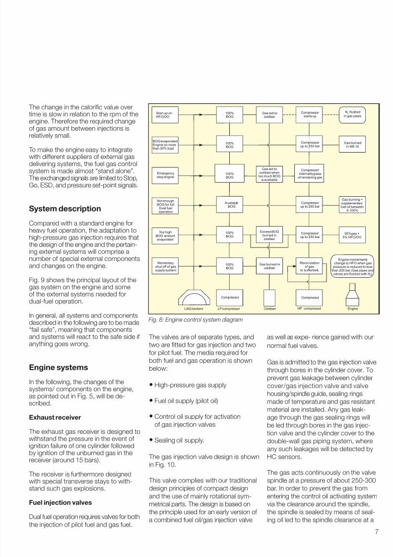
Fig. 8: Engine control system diagram
The change in the caloric value overtime is slow in relation to the rpm of theengine. Therefore the required changeof gas amount between injections isrelatively small.
To make the engine easy to integratewith different suppliers of external gasdelivering systems, the fuel gas controlsystem is made almost “stand alone”. The exchanged signals are limited to Stop,Go, ESD, and pressure setpoint signals.
System description
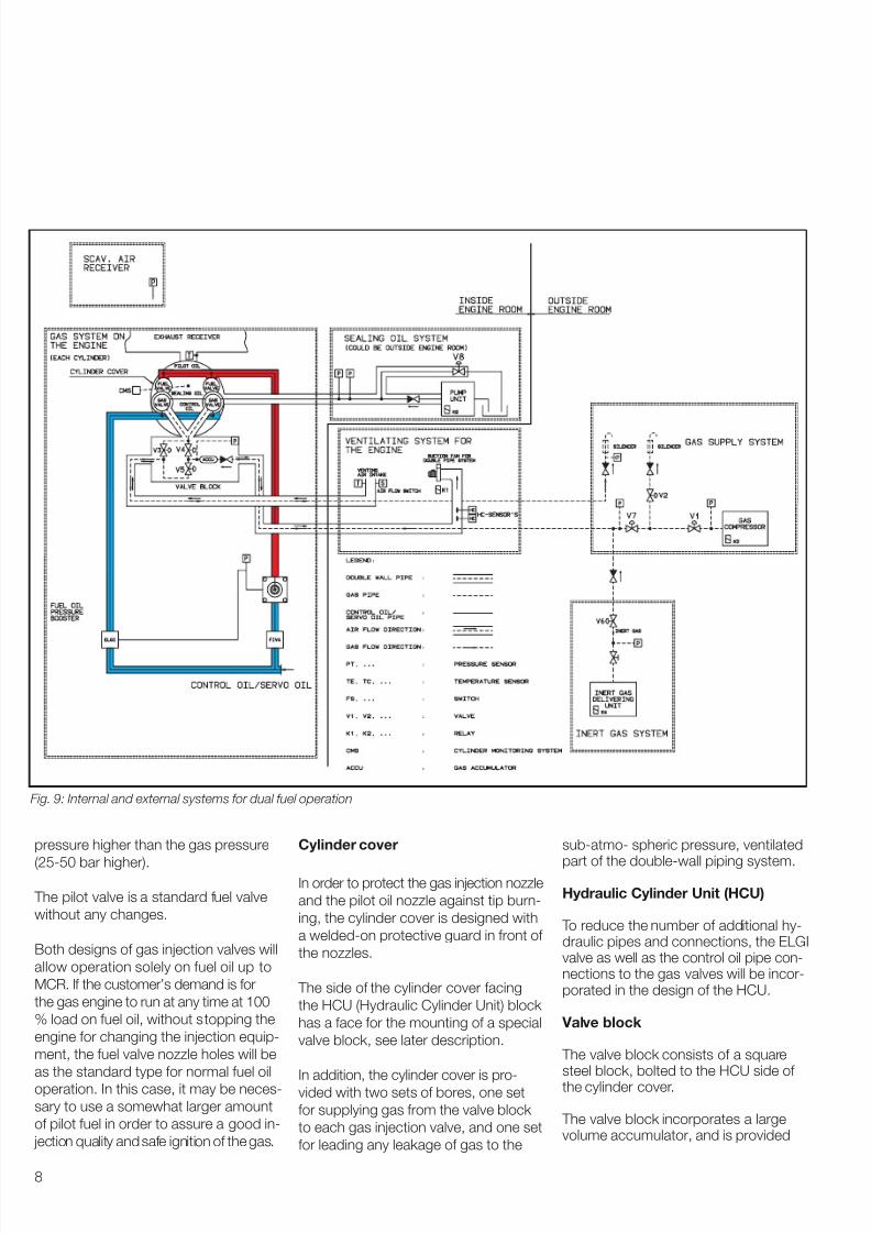
Compared with a standard engine forheavy fuel operation, the adaptation tohighpressure gas injection requires thatthe design of the engine and the pertain-ing external systems will comprise anumber of special external componentsand changes on the engine.
Fig. 9 shows the principal layout of thegas system on the engine and some
of the external systems needed fordualfuel operation.
In general, all systems and componentsdescribed in the following are to be made“fail safe”, meaning that componentsand systems will react to the safe side if anything goes wrong.
Engine systems
In the following, the changes of the
systems/ components on the engine,as pointed out in Fig. 5, will be de-scribed.
Exhaust receiver
The exhaust gas receiver is designed towithstand the pressure in the event of ignition failure of one cylinder followedby ignition of the unburned gas in thereceiver (around 15 bars).
The receiver is furthermore designedwith special transverse stays to with-
stand such gas explosions.
Fuel injection valves
Dual fuel operation requires valves for both
the injection of pilot fuel and gas fuel.
The valves are of separate types, and
two are tted for gas injection and two
for pilot fuel. The media required for
both fuel and gas operation is shown
below:
• Highpressure gas supply
• Fuel oil supply (pilot oil)
• Control oil supply for activation
of gas injection valves
• Sealing oil supply.
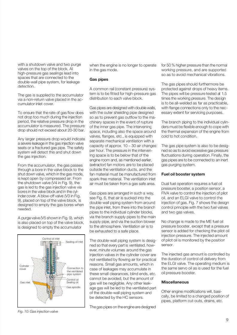
The gas injection valve design is shown
in Fig. 10.
This valve complies with our traditional
design principles of compact designand the use of mainly rotational sym-
metrical parts. The design is based on
the principle used for an early version of
a combined fuel oil/gas injection valve
as well as expe rience gained with our
normal fuel valves.
Gas is admitted to the gas injection valve
through bores in the cylinder cover. To
prevent gas leakage between cylinder
cover/gas injection valve and valve
housing/spindle guide, sealing rings
made of temperature and gas resistant
material are installed. Any gas leak-
age through the gas sealing rings will
be led through bores in the gas injec-
tion valve and the cylinder cover to the
doublewall gas piping system, where
any such leakages will be detected by
HC sensors.
The gas acts continuously on the valve
spindle at a pressure of about 250300
bar. In order to prevent the gas fromentering the control oil activating system
via the clearance around the spindle,
the spindle is sealed by means of seal-
ing oil led to the spindle clearance at a
Emergencystop engine
BOG evaporatedEngine on morethan 30% load
Not enoughBOG for full
Dual fueloperation
TBOG amount
evaporated
oo high
LNG tankers Oxidiser
Start up onHFO/DO
Momentaryshut off of gassupply system
HP compressor
Gas burnedin ME GI
Gas burning +supplementary
fuel oil between5-100%
95%gas +5% HFO/DO
Engine
N flushed
in gas pipes2
Engine momentarilychange to HFO when gas
pressure is reduced to lessthan 200 bar (Gas pipes and
valves are flushed with N )2
Gas led tooxidiser when
too much BOGis available
Excess BOGburned inoxidiser
Gas led tooxidiser
Gas burned inoxidiser
Compressor internal bypass
of remaining gas
Compressor up to 250 bar
Compressor up to 250 bar
Compressor up to 250 bar
Compressor
LP compressor
Compressor starts up
Recirculationof gas
to buffertank
Compressor
100%BOG
100%BOG
100%BOG
100%BOG
100%BOG
AvailableBOG
7/30/2019 P9105
http://slidepdf.com/reader/full/p9105 8/19
8
pressure higher than the gas pressure
(2550 bar higher).
The pilot valve is a standard fuel valve
without any changes.
Both designs of gas injection valves will
allow operation solely on fuel oil up to
MCR. lf the customer’s demand is for
the gas engine to run at any time at 100
% load on fuel oil, without stopping the
engine for changing the injection equip-
ment, the fuel valve nozzle holes will be
as the standard type for normal fuel oil
operation. In this case, it may be neces-
sary to use a somewhat larger amount
of pilot fuel in order to assure a good in-
jection quality and safe ignition of the gas.
Cylinder cover
In order to protect the gas injection nozzle
and the pilot oil nozzle against tip burn-
ing, the cylinder cover is designed with
a weldedon protective guard in front of
the nozzles.
The side of the cylinder cover facing
the HCU (Hydraulic Cylinder Unit) block
has a face for the mounting of a special
valve block, see later description.
In addition, the cylinder cover is pro-vided with two sets of bores, one set
for supplying gas from the valve block
to each gas injection valve, and one set
for leading any leakage of gas to the
subatmo spheric pressure, ventilated
part of the doublewall piping system.
Hydraulic Cylinder Unit (HCU)
To reduce the number of additional hy-draulic pipes and connections, the ELGIvalve as well as the control oil pipe con-nections to the gas valves will be incor-porated in the design of the HCU.
Valve block
The valve block consists of a squaresteel block, bolted to the HCU side of the cylinder cover.
The valve block incorporates a largevolume accumulator, and is provided
Fig. 9: Internal and external systems or dual uel operation
7/30/2019 P9105
http://slidepdf.com/reader/full/p9105 9/19
9
with a shutdown valve and two purgevalves on the top of the block. Allhighpressure gas sealings lead intospaces that are connected to thedoublewall pipe system, for leakagedetection.
The gas is supplied to the accumulatorvia a nonreturn valve placed in the ac-cumulator inlet cover.
To ensure that the rate of gas ow does
not drop too much during the injectionperiod, the relative pressure drop in theaccumulator is measured. The pressuredrop should not exceed about 2030 bar.
Any larger pressure drop would indicatea severe leakage in the gas injection valveseats or a fractured gas pipe. The safetysystem will detect this and shut downthe gas injection.
From the accumulator, the gas passesthrough a bore in the valve block to the
shut down valve, which in the gas mode,is kept open by compressed air. Fromthe shutdown valve (V4 in Fig. 9), thegas is led to the gas injection valve viabores in the valve block and in the cyl-inder cover. A blowoff valve (V3 in Fig.9), placed on top of the valve block, isdesigned to empty the gas bores whenneeded.
A purge valve (V5 shown in Fig. 9), which
is also placed on top of the valve block,
is designed to empty the accumulator
when the engine is no longer to operate
in the gas mode.
Gas pipes
A common rail (constant pressure) sys-
tem is to be tted for highpressure gas
distribution to each valve block.
Gas pipes are designed with double walls,
with the outer shielding pipe designed
so as to prevent gas outow to the ma-chinery spaces in the event of rupture
of the inner gas pipe. The intervening
space, including also the space around
valves, anges, etc., is equipped with
separate mechanical ventilation with a
capacity of approx. 10 – 30 air changes
per hour. The pressure in the interven-
ing space is to be below that of the
engine room and, as mentioned earlier,
(extractor) fan motors are to be placed
outside the ventilation ducts, and the
fan material must be manufactured fromsparkfree material. The ventilation inlet
air must be taken from a gas safe area.
Gas pipes are arranged in such a way,
see Fig. 6, that air is sucked into the
doublewall piping system from around
the pipe inlet, from there into the branch
pipes to the individual cylinder blocks,
via the branch supply pipes to the main
supply pipe, and via the suction blower
to the atmosphere. Ventilation air is to
be exhausted to a safe place.
The doublewall piping system is desig
ned so that every part is ventilated. how
ever, minute volumes around the gas
injection valves in the cylinder cover are
not ventilated by owing air for practical
reasons. Small gas amounts, which in
case of leakages may accumulate in
these small clearances, blind ends, etc.
cannot be avoided, but the amount of
gas will be negligible. Any other leak-
age gas will be led to the ventilated part
of the doublewall piping system andbe detected by the HC sensors.
The gas pipes on the engine are designedFig. 10: Gas injection valve
Cylinder
cover
Gas inlet
Gas spindle
Sealing oilControl oil
Connection to
the ventilatedpipe system
Sealing oil inlet
Control oil inlet
for 50 % higher pressure than the normal
working pressure, and are supported
so as to avoid mechanical vibrations.
The gas pipes should furthermore be
protected against drops of heavy items.
The pipes will be pressure tested at 1.5
times the working pressure. The design
is to be allwelded as far as practicable,
with ange connections only to the nec-
essary extent for servicing purposes.
The branch piping to the individual cylin-
ders must be exible enough to cope with
the thermal expansion of the engine from
cold to hot condition.
The gas pipe system is also to be desig
ned so as to avoid excessive gas pressure
uctuations during operation. Finally, the
gas pipes are to be connected to an inert
gas purging system.
Fuel oil booster system
Dual fuel operation requires a fuel oil
pressure booster, a position sensor, a
FIVA valve to control the injection of pilot
oil, and an ELGI valve to control the
injection of gas. Fig. 7 shows the design
control principle with the two fuel valves
and two gas valves.
No change is made to the ME fuel oil
pressure booster, except that a pressure
sensor is added for checking the pilot oil
injection pressure. The injected amountof pilot oil is monitored by the position
sensor.
The injected gas amount is controlled by
the duration of control oil delivery from
the ELGI valve. The operating medium is
the same servo oil as is used for the fuel
oil pressure booster.
Miscellaneous
Other engine modications will, basi-cally, be limited to a changed position of
pipes, platform cutouts, drains, etc.

7/30/2019 P9105
http://slidepdf.com/reader/full/p9105 10/19
10
Safety aspects
The normal safety systems incorpo-
rated in the fuel oil systems are fully
retained also during dual fuel operation.
However, additional safety devices will
be incorporated in order to prevent situ-
ations which might otherwise lead to
failures.
Safety devices – External systems
Leaky valves and fractured pipes are
sources of faults that may be harmful.
Such faults can be easily and quickly
detected by a hydrocarbon (HC) analyser
with an alarm function. An alarm is given
at a gas concentration of max. 30% of
the Lower Explosion Limit (LEL) in the
vented duct, and a shut down signal is
given at 60% of the LEL.
The safety devices that will virtually
eliminate such risks are doublewall
pipes and encapsulated valves with
ventilation of the intervening space. The
ventilation between the outer and inner
walls is
always to be in operation when there
is gas in the supply line, and any gas
leakage will be led to the HCsensors
placed in the outer pipe.
Another source of fault could be a mal-
functioning sealing oil supply system. If
the sealing oil pressure becomes too low
in the gas injection valve, gas will owinto the control oil activation system
and, thereby, create gas pockets and
prevent the ELGI valve from operating
the gas injection valve. Therefore, the
sealing oil pressure is measured by a set
of pressure sensors, and in the event of
a too low pressure, the engine will shut
down the gas mode and start running in
the fuel oil mode.
Lack of ventilation in the doublewall
piping system prevents the safetyfunction of the HC sensors, so the
system is to be equipped with a set of
ow switches. If the switches indicate
no ow, or nearly no ow, an alarm is
given. If no correction is carried out, the
engine will be shut down on gas mode.
The switches should be of the normally
open (NO) type, in order to allow detec-
tion of a malfunctioning switch, even in
case of an electric power failure.
• In case of malfunctioning valves (not
leaky) resulting in insufcient gas sup-
ply to the engine, the gas pressure
will be too low for gas operation. This
is dealt with by monitoring the pres-sure in the accumulator in the valve
block on each cylinder. The pressure
could be monitored by either one
pressure pickup, or by a pressure
switch and a differential pressure
switch (see later for explanation).
As natural gas is lighter than air,
nonreturn valves are incorporated in
the gas system’s outlet pipes to ensure
that the gas system is not polluted,
i.e. mixed with air, thus eliminating the
potential risk of explosion in case of a
sudden pressure increase in the system
due to quick opening of the main gas
valve.
For LNG carriers in case of too low
a BOG pressure in the LNG tanks, a
stop/off signal is sent to the MEGI
control system and the gas mode is
stopped, while the engine continues
running on HFO.
Safety devices – Internal systems
During normal operation, a malfunction
in the pilot fuel injection system or gas
injection system may involve a risk of
uncontrolled combustion in the engine.
Sources of faults are:
• Defective gas injection valves
• Failing ignition of injected gas
These aspects will be discussed in detail
in the following together with the suitable
countermeasures.
Defective gas injection valves
In case of sluggish operation or even
seizure of the gas valve spindle in the
open position, larger gas quantities
may be injected into the cylinder, and
when the exhaust valve opens, a hot
mixture of combustion products and
gas ows out and into the exhaust pipe
and further on to the exhaust receiver.
The tempe rature of the mixture after
the valve will increase considerably, andit is likely that the gas will burn with a
diffusion type ame (without exploding)
immediately after the valve where it is
mixed with scavenge air/exhaust gas
(with approx. 15 per cent oxygen) in
the exhaust
system. This will set off the high exhaust
gas temperature alarm for the cylinder
in question. In the unlikely event of larger
gas amounts entering the exhaust re-
ceiver without starting to burn immedi-
ately, a later ignition may result in violent
burning and a corresponding pressure
rise. Therefore, the exhaust receiver is
designed for the maximum pressure
(around 15 bars).
However, any of the abovementioned
situations will be prevented by the de-
tection of defective gas valves, which
are arranged as follows:
The gas ow to each cylinder during one
cycle will be detected by measuring the
pressure drop in the accumulator. Thisis to ensure that the injected gas amount
does not exceed the amount correspon
ding to the MCR value.
It is necessary to ensure that the pres-
sure in the accumulator is sufcient for
gas operation, so the accumulator will
be equipped with a pressure switch
and a differential pressure switch. An
increase of the gas ow to the cylinder
which is greater than corresponding to
the actual load, but smaller than corre-sponding to the MCR value, will only give
rise to the abovementioned exhaust gas
temperature alarm, and is not harmful.
By this system, any abnormal gas ow,
whether due to seized gas injection valves
7/30/2019 P9105
http://slidepdf.com/reader/full/p9105 11/19
11
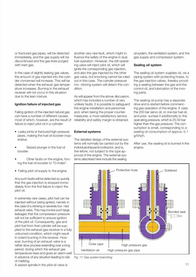
Fig. 11: Gas system branching
or fractured gas pipes, will be detected
immediately, and the gas supply will be
discontinued and the gas lines purged
with inert gas.
In the case of slightly leaking gas valves,
the amount of gas injected into the cylin-
der concerned will increase. This will be
detected when the exhaust gas temper-
ature increases. Burning in the exhaust
receiver will not occur in this situation
due to the lean mixture.
Ignition failure of injected gas
Failing ignition of the injected natural gas
can have a number of different causes,
most of which, however, are the result of
failure to inject pilot oil in a cylinder:
• Leaky joints or fractured highpressure
pipes, making the fuel oil booster inop-
erative.
• Seized plunger in the fuel oil
booster.
• Other faults on the engine, forc-
ing the fuel oil booster to “Oindex”.
• Failing pilot oil supply to the engine.
Any such faults will be detected so quickly
that the gas injection is stopped imme-
diately from the rst failure to inject the
pilot oil.
In extremely rare cases, pilot fuel can be
injected without being ignited, namely in
the case of a sticking or severely bur ned
exhaust valve. This may involve such large
leakages that the compression pressure
will not be sufcient to ensure ignition
of the pilot oil. Consequently, gas and
pilot fuel from that cylinder will be sup-
plied to the exhaust gas receiver in a fully
unburned condition, which might result
in violent burning in the receiver. How-
ever, burning of an exhaust valve is arather slow process extending over a long
period, during which the exhaust gas
temperature rises and gives an alarm well
in advance of any situation leading to risk
of misring.
A seized spindle in the pilot oil valve is
another very rare fault, which might in-
uence the safety of the engine in dual
fuel operation. However, the still operat-
ing valve will inject pilot oil, which will
ignite the corresponding gas injection,
and also the gas injected by the other
gas valve, but knocking cannot be ruled
out in this case. The cylinder pressure
mo nitoring system will detect this con-
dition.
As will appear from the above discussion,which has included a number of very
unlikely faults, it is possible to safeguard
the engine installation and personnel
and, when taking the proper counter-
measures, a most satisfactory service
reliability and safety margin is obtained.
External systems
The detailed design of the external sys
tems will normally be carried out by the
individual shipyard/contractor, and is,
therefore, not subject to the type ap-
proval of the engine. The external sys-
tems described here include the sealing
oil system, the ventilation system, and the
gas supply and compressor system.
Sealing oil system
The sealing oil system supplies oil, via a
piping system with protecting hoses, to
the gas injection valves, thereby provid-
ing a sealing between the gas and the
control oil, and lubrication of the mov-
ing parts.
The sealing oil pump has a separate
drive and is started before commenc-
ing gas operation of the engine. It uses
the 200 bar servo oil, or one bar fuel oil,
and pres surises it additionally to the
operating pressure, which is 2550 bar
higher than the gas pressure. The con-
sumption is small, corresponding to a
sealing oil consumption of approx. 0.1
g/bhph.
After use, the sealing oil is burned in the
engine.
Protective hose Soldered
Bonded seal
High pressure gas
High pressure gas pipe
Outer pipe
Ventilation air

7/30/2019 P9105
http://slidepdf.com/reader/full/p9105 12/19
12
Ventilation system
The purpose of the ventilation system
is to ensure that the outer pipe of the
doublewall gas pipe system is ventilated
with air, and it acts as a separation
between the engine room and the
highpressure gas system, see Fig 11.
Ventilation is achieved by means of an
electrically driven mechanical fan or
extractor fan. If an electrically drivenfan is chosen, the motor must be placed
outside the ventilation duct. The ca-
pacity must ensure approx. 10 – 30
air changes per hour. More ventilation
gives quicker detection of any gas leak-
age.
The gas CompressorSystem
The gas supply system is based on Flo-
tech™ packaged compressors:
• Lowpressure GE Oil & Gas RoFlo™
type gas compressors with lubricated
vanes and oil buffered mechanical seals,
which compress the cold boiloff gas
from the LNG tanks at the temperature
of 140oC to 160oC. The boiloff gas
pressure in the LNG tanks should
normally be kept between 1.061.20
bar(a). Under normal running conditions,
cooling is not necessary, but during
start up, the temperature of the boiloff
gas may have risen to atmospheric
temperature, hence preheating and
aftercooling is included, to ensure
stabilisation of the cold inlet and inter-
mediate gas. temperature
• The highpressure GE Oil & GasNuovo Pignone™ SHMB type gas
compressor; 4 throw, 4stage hori-
zontally opposed and fully balanced
crosshead type with pressure lubri-
cated and watercooled cylinders
& packings, compresses the gas to
approximately 250300 bar, which is
the pressure required at the engine
inlet at full load. Only reciprocating
piston compressors are suitable for
this highpressure duty; however the
unique GE fully balanced frame layout
addresses concerns about transmit-
ted vibrations and also eliminates the
need for heavy installation structure, as
is required with vertical or Vform unbal-
anced compres sor designs. The dis-
charge temperature is kept at approx.
45oC by the coolers.
•Buffer tank/accumulators are installedto provide smoothing of minor gas
pressure uctuations in the fuel sup-
ply; ± 2 bar is required.
• Gas inlet lter/separator with strainer
for protection against debris.
• Discharge separator after the nal stage
gas cooler for oil/condensate remov-
al.
• Compressor capacity control system
ensures that the required gas pres-
sure is in accordance with the engine
load, and that the boiloff gas amount
is regulated for cargo tank pressure
control (as described later).
• The compressor safety system handles
normal start/stop, shutdown and
emergency shutdown commands.
Fig. 12: Gas supply system – natural BOG only
65%
65%
65%
65%
65% 65%
65%
natural BOG
LNG
Tank
LP.+ comp.
LP.+ comp.
HP comp. MEGI
GCU
Redundant gas supply system comprising
2 xLow Pressure compressors.1 x gas combustion unit GCU
1 xHighPressure piston compressor.
Add up with 35 % HFO
+ pilot oil

7/30/2019 P9105
http://slidepdf.com/reader/full/p9105 13/19
13
Fig. 13: Gas supply system– natural and orced BOG
The compressor unit includes a pro-
cess monitoring and fault indication
system. The compressor control
system exchanges signals with the
MEGI control system.
• The compressor system evaluates
the amount of available BOG and
reports to the MEGI control system.
Redundancy for the gas supply system
is a very important issue. Redundancy
in an extreme sense means two of all
com ponents, but the costs are heavy
and a lot of space is required on board
the ship. We have worked out a reco-mendation that reduces the costs and
the requirement for space while ensur-
ing a fully operational MEGI engine. The
dual fuel en gine concept, in its nature,
includes redunancy. If the gas supply
system falls out, the engine will run on
heavy fuel oil only.
The gas supply system illustrated in Fig.
12 and 13 are based on a 210,000 M3
LNG carrier, a boil off rate of 0.12 and
equipped with 2 dual fuel engines: 2 x7S65MEGI. For other sizes of LNG car-riers the setup will be the same but the
% will be changed. Figs. 12 and 13 show
our recommendations for a gas sup-ply system to be used on LNG carriers,
Fig. 14: Typical HP uel oil gas compressor
and gure 15 shows the compressor
system in more detail. Depending onwhether the ship owner wishes to run
on natural BOG only, Fig. 12, or run onboth natural BOG and forced BOG, Fig.13 is relevant.
Both systems comprise a double (2 x
100%) set of Low Pressure compres-
sors each with the capacity to handle
100% of the natural BOG if one falls out
(alternatively 3 x 50% may be chosen).
Each of these LP compressors can in-
dividually feed both the High Pressure
Compressor and the Gas Combustion
Unit. All compressors can run simulta-
neously, which can be utilised when the
engine is fed with both natural and
forced BOG.
The HP compressor section is chosen to
be a single unit. If this unit falls out then
the MEGI engine can run on Heavy Fuel
Oil, and one of the LP compressors can
feed the GCU.
Typical availability of these electrically
dri ven Flotech / GE Oil & Gas com-pressors on natural gas (LNG) service is
98%, consequently, an extra HP com-
pressor is a high cost to add for the 2%
extra availability.
Gas supply system –capacity
management
The minimum requirement for the regu-
lation of supply to the MEGI engine is
a turndown ratio of 3.33 which equals a
regulation down to 30% of the maximum
ow (For a twin engine system, the TRis 6.66). Alternatively in accordance with
the requirements of the ship owners
Both the LP and HP compressor pack-
ages have 0 => 100% capacity variation
systems, which allows enormous ex-
ibility and control.
Stable control of cargo tank pressure is
the primary function of the LP compres-
sor control system. Dynamic capacity
variation is achieved by a combination
100%
65%
65%
65%
100% 100%
65%naturalBOG
35%forcedBOG
LNG Tank
LP.+ comp.
LP.
+ comp.
HP Comp. MEGI
GCU
Redundant gas supply system comprising
2 x Low pressure compressors.
1 x gas combustion unit GCU
1 x High pressure piston compressor.
No Add up with HFOExpect from pilot oil
7/30/2019 P9105
http://slidepdf.com/reader/full/p9105 14/19
14
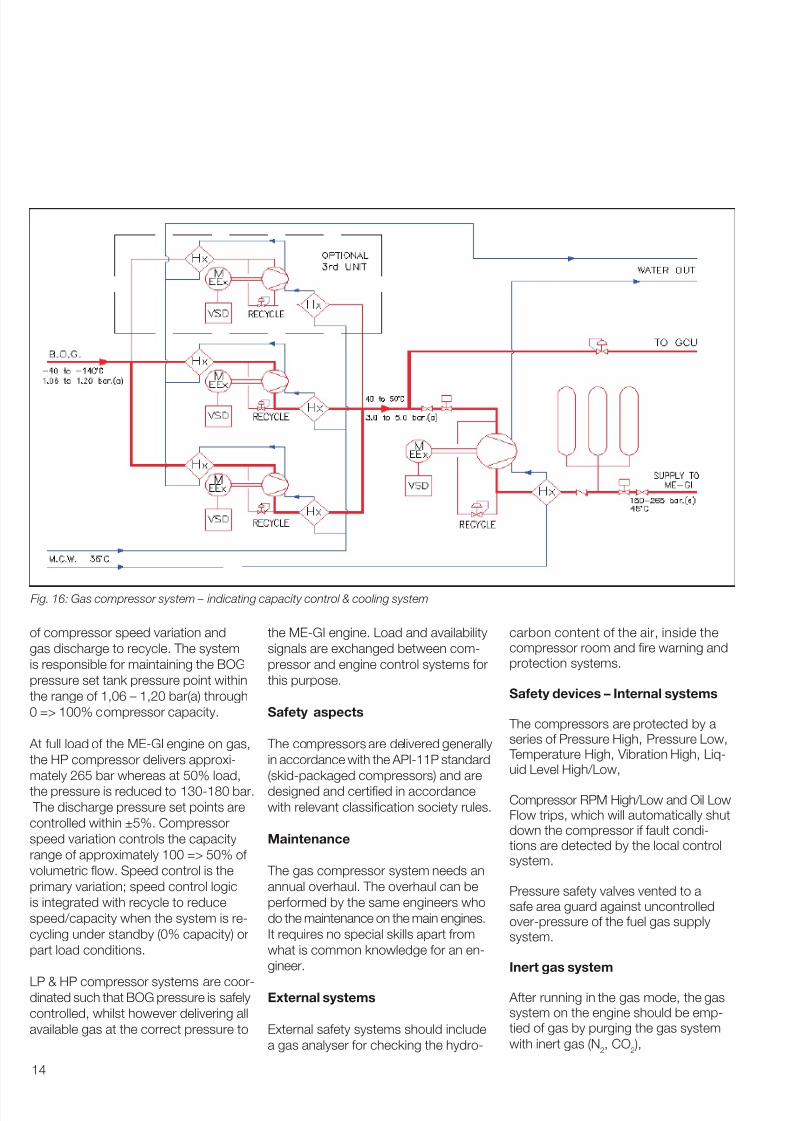
of compressor speed variation and
gas discharge to recycle. The system
is responsible for maintaining the BOG
pressure set tank pressure point within
the range of 1,06 – 1,20 bar(a) through
0 => 100% compressor capacity.
At full load of the MEGI engine on gas,
the HP compressor delivers approxi-
mately 265 bar whereas at 50% load,
the pressure is reduced to 130180 bar.
The discharge pressure set points are
controlled within ±5%. Compressor
speed variation controls the capacity
range of approximately 100 => 50% of
volumetric ow. Speed control is the
primary variation; speed control logic
is integrated with recycle to reduce
speed/capacity when the system is re-
cycling under standby (0% capacity) or
part load conditions.
LP & HP compressor systems are coor-dinated such that BOG pressure is safely
controlled, whilst however delivering all
available gas at the correct pressure to
the MEGI engine. Load and availability
signals are exchanged between com-
pressor and engine control systems for
this purpose.
Safety aspects
The compressors are delivered generally
in accordance with the API11P standard
(skidpackaged compressors) and are
designed and certied in accordance
with relevant classication society rules.
Maintenance
The gas compressor system needs an
annual overhaul. The overhaul can be
performed by the same engineers who
do the maintenance on the main engines.
It requires no special skills apart from
what is common knowledge for an en-
gineer.
External systems
External safety systems should include
a gas analyser for checking the hydro-
carbon content of the air, inside thecompressor room and re warning andprotection systems.
Safety devices – Internal systems
The compressors are protected by aseries of Pressure High, Pressure Low, Temperature High, Vibration High, Liq-uid Level High/Low,
Compressor RPM High/Low and Oil LowFlow trips, which will automatically shutdown the compressor if fault condi-tions are detected by the local controlsystem.
Pressure safety valves vented to asafe area guard against uncontrolledoverpressure of the fuel gas supplysystem.
Inert gas system
After running in the gas mode, the gassystem on the engine should be emp-tied of gas by purging the gas system
with inert gas (N2, CO
2 ),
Fig. 16: Gas compressor system – indicating capacity control & cooling system

7/30/2019 P9105
http://slidepdf.com/reader/full/p9105 15/19
15
Dual Fuel Control System
General
In addition to the above a special dual
fuel control system is being developed
to control the dualfuel operation when
the engine is operating on compressed
gaseous fuels. See g. 17. The control
system is the glue that ties all the dual
fuel parts in the internal and the external
system together and makes the engine
run in gas mode.
As mentioned earlier the system is
designed as an addon system to the
original ME control system. The conse-
quence is that the Bridge panel, the Main
Operating Panel (MOP) & the Local Op-
erating Panel (LOP) will stay unchanged.
All operations in gas mode are therefore
performed from the engine room alone.
When the dual fuel control system isrunning the existing ME control and
alarm system will stay in full operation.
Mainly for hardware reasons the control
of the dual fuel operation is divided into:
• Plant control
• Fuel control
• Safety Control
Plant control
The task of the plant control is to handle
the switch between the two stable
states:
• Gas Safe Condition State ( HFO only)
• DualFuel State
The plant control can operate all the fuel
gas equipment shown in g. 10. For theplant control to operate it is required
that the Safety Control allows it to work
otherwise the Safety Control will overrule
and return to a Gas Safe Condition.
Fuel control
The task of the fuel control is to deter-
mine the fuel gas index and the pilot oil
index when running in the three different
modes shown in g.4.
Safety control
The task of the safety system is to monitor:
•All fuel gas equipment and the relatedauxiliary equipment
• The existing shut down signal from
the ME safety system.
• The cylinder condition for being in a con
dition allowing fuel gas to be injected.
If one of the above mentioned failures is
detected then the Safety Control releases
the fuel gas Shut Down sequence be-
low:
The Shut down valve V4 and the master
valve V1 will be closed. The ELGI valves
will be disabled. The uel gas will be blow
out by opening valve V2 and fnally the
gas pipe system will be purged with in-
ert gas. See also fg. 9
Architecture of the Dual Fuel Control
System
Dual Fuel running is not essential for the
manoeuvrability of the ship as the enginewill continue to run on fuel oil if an un-
intended fuel gas stop occurs. The two
fundamental architectural and design
demands of the fuel gas Equipment are,
in order of priority:
• Safety to personnel must be at least
on the same level as for a conven-
tional diesel engine
• A fault in the Dual Fuel equipment
must cause stop of gas operationand change over to Gas Safe Condi-
tion.
Which to some extent complement each
other.
The Dual Fuel Control System is designed
to “fail to safe condition”. See Fig. 18.
All failures detected during fuel gas run-
ning and failures of the control system
itself will result in a fuel gas Stop / Shut
Down and change over to fuel opera-
tion. Followed by blow out and purging
of high pressure fuel gas pipes which
releases all gas from the entire gas sup-ply system.
If the failure relates to the purging sys-
tem it may be necessary to carry out
purging manually before an engine
repair is carried out. (This will be ex-
plained later).
The Dual Fuel Control system is a single
system without manual backup con-
trol.
However, the following equipment is
made redundant to secure that a single
fault will not cause fuel gas stop:
• The communication network is doub
led in order to minimize the risk of in-
terrupting the communication between
the control units.
• Vital sensors are doubled and one set
of these sensors is connected to the
Plant Control and the other to the Safety
System. Consequently a sensor failurewhich is not detectable is of no con-
sequence for safe fuel gas operation.
Control Unit Hardware For the Dual Fuel Control System twodifferent types of hardware are used:the Multi Purpose Controller Units and the GCSU , both developed byMAN B&W Diesel A/S.
The Multi Purpose Controller Units are
used for the following units: GECU, GACU,GCCU, and the GSSU see also g. 17.In the following a functionality descrip-
tion for each units shown in g. 17

7/30/2019 P9105
http://slidepdf.com/reader/full/p9105 16/19
16
Gas Main Operating Panel (GMOP )
For the GI control system an extra panelcalled GMOP is introduced. From here
all manually operations can be initiated.
For example the change between the
different running modes can be doneand the operator has the possibility to
manually initiate the purging of the gaspipes system with inert gas.
Additionally it contains the facilities to
manually start up or to stop on fuel gas.
GECU, Plants control
The GECU handles the Plant Controland in combination with GCCU it also
handles Fuel Control.
Example: When “dual fuel” Start is initiated
manually by the operator, the Plant
Control will start the automatic start
sequence which will initiate startup of
the sealing oil pump. When the engine
condition for Dual Fuel running, which
is monitored by the GECU, is conrmed
to meet the prescribed demands, the
Plant Control releases a “Start Dual Fuel
Operation” signal for the GCCU (Fuel
Control).
In combination with the GCCU, the
GECU will effect the fuel gas injection if
all conditions for Dual Fuel running are
fullled.
The Plant Control monitors the condi-
tion of the following:
• HC “Sensors”
• Gas Supply System
• Sealing Oil System
• Pipe Ventilation
• Inert Gas System
• Network connection to other units of
the Dual Fuel System
and, if a failure occur, the Plant Control
will automatically interrupt fuel gas start
operation and return the plant to Gas
Safe Condition.
The GECU also contains the Fuel Con-
trol which includes all facilities required
for calculating the fuel gas index and
the Pilot Oil index based on the com-
mand from the conventional governor
and the actual active mode.Based on these data and including in-
formation about the fuel gas pressure,
the Fuel Control calculates the start
Fig. 17: MEGI Control System
On Bridge
In Engine Control Room
In Engine Room/
On Engine
ECU A
EICU A EICU B
ECU B
ADMINISTRATION PC
BACK-UP FOR MOP
BRIDGE PANEL
LOCAL OPERATION
PANEL - LOP
ECR PANEL
CRANKSHAFTPOSITION
SENSOR - MSA
CCU
Cylinder 1
CCU
Cylinder n
ALS
SAV
Cylinder n
HCUCylinder n
ALS
SAV
Cylinder 1
HCUCylinder 1
MAIN OPERATION
PANEL - MOP
Cylinder 1 Cylinder n
GCCU
Cylinder 1-6
GCCU
Cylinder 7-12
ELGI
Cylinder 1 = n= 6
ELGI
Cylinder 7 = n= 12
P U M P 3
P U M P 2
M M M
P U M P 1
F i l t e r
P U M P 1
M
P U M P 2
M
HPS
AUXILIARY
BLOWER 1
AUXILIARY
BLOWER 2
ACU 1 ACU 3ACU 2
GACU 1
Inert
gas
Sealing
oilFAN
GACU 2
10 Amp
Sipply
GMOP
GECU GSSU 1
1-6 cyl.
GSSU 2
7-12 cyl.
GCSU 1 GCSU 2
PMI
(on-line)
PMI
(on-line)
5-8 cyl.1-4 cyl.
ME - Control
GCSU 3
PMI
(on-line)
9-12 cyl.
Hardwire interface
with ME
ME
GI
Angle Encoders
Angle Encoders + MSA = Tacho system
TSA A/B
MEECU Engine Control UnitEICU Engine Interface Control Unit
ACU Auxiliary Control UnitCCU Cylinder Control UnitHPS Hydraulic Power SupplySAV Starting Air ValveCPS Crankshaft Position Sensors
ALS Alpha Lubricator SystemMOP Main Operation PanelLOP Local Operation Panel
GIGCSU Gas Cylinder Safety Unit per 4 cylinderGSSU Gas System Safety Unit per 6 cylinderGECU Gas Engine Control UnitGMOP Gas Main Operation Panel
GACU Gas Auxiliary Control UnitGCCU Gas Cylinder Control Unit per 6 cylinder

7/30/2019 P9105
http://slidepdf.com/reader/full/p9105 17/19
17
and duration time of the injection, then
sends the signal to GCCU which ef-
fectuates the injection by controlling the
ELGI valve.
GACU, Auxiliary Control
The GACU contains facilities necessary
to control the following auxiliary systems:
The fan for ventilating of the double wall
pipes, the sealing oil pump, the purgingwith inert gas and the gas supply system.
The GACU controls:
• Start/stop of pumps, fans, and of the
gas supply system.
• The sealing oil pressure set points
• The pressure set points for the gas
supply system.
GCCU, ELGI control
The GCCU controls the ELGI valve on
the basics of data calculated by the
GECU.
In due time before each injection the
GCU receives information from the GECU
of start timing for fuel gas injection, and
the time for the injection valve to stay
open. If the GCCU receive a signal ready
from the safety system and GCCU ob-
serves no abnormalities then the injec-
tion of fuel gas will starts at the relevant
crankshaft position.
The GSSU, fuel gas System Monitor-
ing and Control
The GSSU performs safety monitoring
of the fuel gas System and controls thefuel gas Shut Down.
It monitors the following:
• Status of exhaust gas temperature
• Pipe ventilation of the double wall
piping
• Sealing Oil pressure
• Fuel gas Pressure
• GCSU ready signal
If one of the above parameters, referring
to the relevant fuel gas state differs from
normal service value, the GSSU over-
rules any other signals and fuel gas shut
down will be released.
After the cause of the shut down has
been corrected the fuel gas operation
can be manually restarted.
GCSU, PMI online
The purpose of the GCSUs is to moni-
tor the cylinders for being in condition
for injection of fuel gas. The following
events are monitored:
• Fuel gas accumulator pressure drop
during injection
• Pilot oil injection pressure
• Cylinder pressure:
Low compression pressure
Knocking
Low Expansion pressure
• Scavenge air pressure
If one of the events is abnormal theELGI valve is closed and a shut down of
fuel gas is activated by the GSSU.
Safety remarks
The primary design target of the dual
fuel concept is to ensure a Dual Fuel
Control System which will provide the
highest possible degree of safety to
personnel. Consequently, a failure in the
gas system will, in general, cause shut
down of fuel gas running and subsequent
purging of pipes and accumulators
Fuel gas operation is monitored by the
safety system, which will shut down fuel
gas operation in case of failure. Additio
nally, fuel gas operation is monitored by
the Plant Control and the Fuel Control,
and fuel gas operation is stopped if
one of the systems detects a failure. As
parameters vital for fuel gas operation
are monitored, both by the Plant Control/
Fuel Control and the Safety Control
System, these systems will provide mu-tual backup.
Fig. 18: Fuel gas operation state model
Start of auxiliary
equipment
Start of fuel
gas supply
Running on
fuel gasSafe condition
Stop to safecondition
Purging
Safe condition/
purged system

7/30/2019 P9105
http://slidepdf.com/reader/full/p9105 18/19
18
Summary
The twostroke engine technol-
ogy is a most widely used and
stateoftheartsolution for optimum
utilisation of the fuel when burning HFO
and gas.
The technology selected for the
twostroke solutions, such as gas
compres sors, is wellproven from the
LNG and power generation industries.
The control and safety system for the
MEGI system is based on the experi-
ence obtained from working gas plants,
including the 12K80MCGIS in Japan,
and cooperation with the Classication
Societies.
The twostroke diesel engine of today is
superior to the traditional steam turbine
solution with regard to the operating
economy, when the MEGI engine is
chosen
REFERENCES
BOG Boiloff gas
CIMAC Congress International des, Machines a Combustion
CNG Compressed natural gas
ELGIvalve Electronic gas injection
ESD Emergency shutdown
FIVAvalve Fuel injection valve actuator
GACU Gas auxiliary control unit
GCCU Gas cylinder control unit
GCSU Gas control safety unit
GECU Gas engine control unit
GSSU Gas system safety unit
HFO Heavy fuel oil
LNG Liquied natural gasMCR Maximum continuous rating
MEGI ME engine with gas injection
PMI Pressure mean indicator
TR Turndown ratio
Abbreviations
[1] “LNG Carriers with Low Speed
Diesel Propulsion”, Ole Grøne,
The SNAME Texas Section14th
Annual Offshore Symposium,
November 10, 2004, Houston, Texas
[2] “Basic Principles of Ship Propulsion”,
p.254 – 01.04, January 2004,
MAN B&W Diesel A/S
[3] “MEGI Engines for LNG Application”
System Control and Safety Feb. 2005
Ole Grøne, Kjeld Aabo,
Rene Sejer Laursen,
MAN B&W Diesel A/S
Steve Broadbent,Flotech

7/30/2019 P9105
http://slidepdf.com/reader/full/p9105 19/19


