Embed Size (px)
Citation preview

GeneralAccuracy: Stated accuracy at 0 to 50°C (32 to
122°F): ±1.5% FS
Battery: Single standard 9-volt battery, NEDA
1604, JIS 006P, IEC 6F22.
Battery Life: 200 hours with low battery indicator
on display.
Operating environment:
32ºF (0°C) to 122ºF (50°C)
Compatible Media: Dry, non-corrosive gases
Overrange: “OL” or “-OL” is displayed.
Auto-Off power: 15 minutes
Low Battery: symbol is displayed.
Dimensions: 180mm(~7 1/16”)(H) x 60mm(~2
3/8”)(W) x 30mm(~1 3/16”)(D)
Weight: approximately 195g including battery
PressurePressure Ports: tube connectors for 5mm (~3/16
inch) I.D. flexible tubing
Units of Measure: inWC, mmWC, mbar, PSI
Resolution: 0.01 inch WC
Accuracy/Ranges:
inWC: ±0.02 on 0.00 to ±2.00
±1.5% FS on 2.00 to ±60.0
mmWC: ±0.5 on 0.00 to ±51.0
±1.5% FS on 51.0 to ±1500
mbar: ±0.05 on 0.00 to ±5.00
±1.5% FS on 5.00 to ±150.0
psi: ±0.001 on 0.000 to ±0.07
±1.5% FS on 0.07 to ±2.000
RMA316 Manometer AdapterUsed for 5/16" pressure outlet ports.
1. Shut off main gas supply to furnace.
2. Move the gas valve switch to "OFF" position.
3. Use a 3/32" hex wrench to loosen the outlet
pressure tap screw. Rotate screw counter-
clockwise one revolution to open.
4. Connect the SDMN5 tubing to the smaller
(3/16") end of the adapter and the other (5/16")
end of the adapter into the of the adapter tube.
5. Slide the 5/16" adapter tube over the outlet
pressure boss (port) to seal. Overlap the pres-
sure boss by at least 3/8" to prevent leakage.
WarrantyThe product is warranted to the original purchas-
er against defects in material or workmanship for a
period of one (1) year from the date of purchase.
During the warranty period, Fieldpiece Instruments
will, at its option, replace or repair the defective unit.
This warranty does not apply to defects resulting
from abuse, neglect, accident, unauthorized repair,
alteration, or unreasonable use of the instrument.
Any implied warranty arising out of the sale of
Fieldpiece's products including but not limited to
implied warranties of merchantability, and fitness for
purpose, are limited to the above. Fieldpiece shall
not be liable for incidental or consequential dam-
ages.
ServiceReturn any defective SDMN5 to Fieldpiece for
warranty service along with proof of purchase.
Contact Fieldpiece for out of warranty repair
charges.
PRESS FOR 1 SECOND
AUTO-OFF BATTERYCHECK
Dual Port Differential
Manometer
Model: SDMN5
OPERATOR’S MANUAL
DescriptionThe SDMN5 is a portable standalone dual port
manometer. The SDMN5 is capable of taking gas
pressure as well as static pressure. The SDMN5
comes in a rugged rubber boot. The SDMN5 also
has a zero adjust and a hold button to hold the cur-
rently displayed reading. The auto-power-off func-
tion conserves battery life, but can be disabled if
desired.
The SDMN5 will allow you to take gas pressure
up to ±60” (152cm) of WC. The SDMN5 will take dif-
ferential pressure readings and display the differ-
ence between P1 and P2 at all times in the lower
right corner of the LCD. The SDMN5 also has four
different measurement scales including inches of
water column, millimeters of water column, mBar
and PSI. Static pressure is possible with the reso-
lution to 0.01” of WC (0.1mmWC). Special purpose
static pressure instruments are on the market with
better accuracy and temperature compensation but
they typically cost many times more than the
SDMN5.
Operation1. Zero SDMN5 by pressing the ZERO just before
taking the pressure readings, while at ambient
pressure. This will zero both P1 and P2. For
measurements less than 2inWC, take reading
within 1 minute after zeroing for best accuracy.
2. Connect a single hose to get the gauge pres-
sure relative to the ambient or ZERO pressure.
3. Connect both hoses if you want to see relative
pressure, P1 minus P2.
4. By pressing the P1 / P2 button you can change
between displaying P1 or P2, P1 - P2 is con-
stantly displayed in the lower right of the LCD.
5. Pressing the unit button makes it possible to
switch between the four measurement scales of
inches of water column (inWC), millimeters of
water column (mmWC), mBar, and PSI. The
scale being viewed is displayed on the right side
of the LCD.
6. To disable the auto-power-off hold the HOLD
button while turning the unit on. If the auto-
power-off is enabled (meter will turn off automat-
ically) an APO will appear on the display. If
Auto-power-off is disabled (meter will not turn off
on its own), then no designation will appear on
the LCD.
7. If you are in an environment where the tempera-
ture is noticeably changing while you are taking
your reading, it is advised that you disconnect
the meter from the hoses and ZERO it relative
to ambient before each reading.
Checking Gas Pressure on a Regulator
1. Screw the brass fitting into the pressure port on
the regulator.
2. Put unit into operation (i.e. turn on the furnace
and have furnace ignite, as if running it in nor-
mal operation.)
3. This will give you the pressure coming out of the
regulator.
4. If you suspect high or low inlet pressure into the
regulator, the manometer can hook into the inlet
port in the same manner it can connect into the
outlet port. If you have a dual-port manometer,
you can check both the inlet and the outlet
simultaneously and see the pressure drop
across the regulator.
5. See manufacturer's specification for target inlet
and outlet pressure for a given regulator or
piece of combustion equipment.
Battery Check Function
Press and hold the UNIT button to display the
percentage of usable battery remaining. This
function can be used any time the meter on.
Field CalibrationPressure:
By pressing the ZERO button, both the P1 and
P2 are zeroed to the pressure they are being
exposed to. For this reason the calibration
should be done when both P1 and P2 are dis-
connected from the hoses.
T2T2T2T2T2T2T2T2T2
T2T2T2T2T2T2T2T2T2T2
P1
P1P2 ZERO
HOLD UNIT
ON/OFF
P2
88.8888.88APO
88.8888.88inWC
mmWC
mbar
psiHOLD
PRESS FOR 1 SECOND
AUTO-OFF BATTERYCHECK
PRESS FOR 1 SECOND
AUTO-OFF BATTERYCHECK
Gas pressure
measurement
Static pressure
across a blower
V15
Outlet Pressure
Tap Screw
Outlet
Pressure
Boss
Inlet Pressure
Tap Screw
Smaller end (3/16”) of the adapter
connects to SDMN5 tubing. Remove
the installed brass fitting from tube
so the adapter can be inserted.
Inlet Pressure
Boss
Adapter
(5/16” to 3/16”)
Adapter Tube
(5/16”)
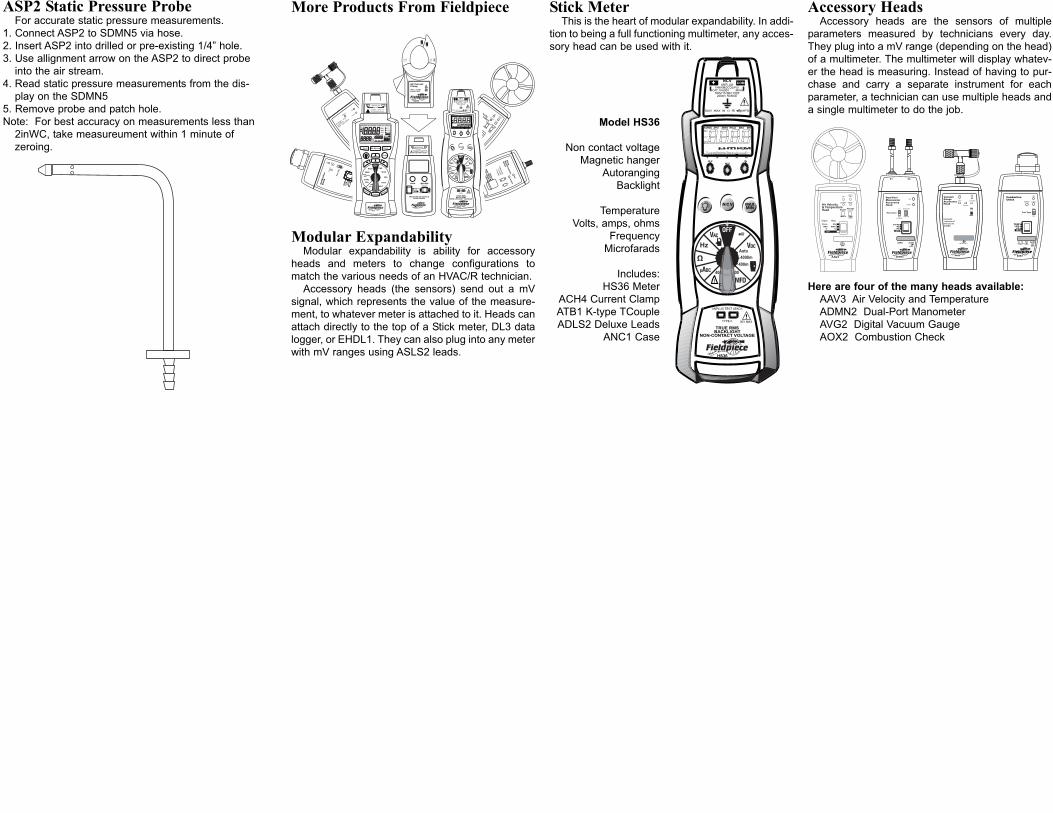
ASP2 Static Pressure ProbeFor accurate static pressure measurements.
1. Connect ASP2 to SDMN5 via hose.
2. Insert ASP2 into drilled or pre-existing 1/4” hole.
3. Use allignment arrow on the ASP2 to direct probe
into the air stream.
4. Read static pressure measurements from the dis-
play on the SDMN5
5. Remove probe and patch hole.
Note: For best accuracy on measurements less than
2inWC, take measureument within 1 minute of
zeroing.
More Products From Fieldpiece
Modular ExpandabilityModular expandability is ability for accessory
heads and meters to change configurations to
match the various needs of an HVAC/R technician.
Accessory heads (the sensors) send out a mV
signal, which represents the value of the measure-
ment, to whatever meter is attached to it. Heads can
attach directly to the top of a Stick meter, DL3 data
logger, or EHDL1. They can also plug into any meter
with mV ranges using ASLS2 leads.
Stick MeterThis is the heart of modular expandability. In addi-
tion to being a full functioning multimeter, any acces-
sory head can be used with it.
Model HS36
Non contact voltage
Magnetic hanger
Autoranging
Backlight
Temperature
Volts, amps, ohms
Frequency
Microfarads
Includes:
HS36 Meter
ACH4 Current Clamp
ATB1 K-type TCouple
ADLS2 Deluxe Leads
ANC1 Case
Accessory HeadsAccessory heads are the sensors of multiple
parameters measured by technicians every day.
They plug into a mV range (depending on the head)
of a multimeter. The multimeter will display whatev-
er the head is measuring. Instead of having to pur-
chase and carry a separate instrument for each
parameter, a technician can use multiple heads and
a single multimeter to do the job.
Here are four of the many heads available:
AAV3 Air Velocity and Temperature
ADMN2 Dual-Port Manometer
AVG2 Digital Vacuum Gauge
AOX2 Combustion Check
CAT.III
300V
400A
CLAMP
ACH4
AC CurrentClamp1AAC / 1mVAC400AAC MAX
!
Air Velocity
&Tem
perature
Head
English
READ
LOBATT
ONLCD
X100
Average(16
sec)
Metric
Realtime
AAV3
AUTO-
OFF
English
Metric
Ft/min
M/sKM
/hr
MPH
ºF
ºC
OFF
AO
X2
Com
bust
ion
Che
ck
%O
%C
OTE
MP
ON
GA
S
OIL
Lo B
att
°C °F
AU
TO
OF
F
STA
BLE
Fu
el Typ
e
2 2
T/C
CA
L
AUTO-
OFF
T/C
Cal
STABLE
Press
ureTe
mp
SHor
SC
ON
LOBATT
R efrig
era tion
Superhe
at
and
Subcooling
ENGLIS
H
METRIC
R134A
R404A
Set
ATM
ASX24
SH
SC
Air Velocity& TemperatureHead English
READLO BATT
ONLCD X100
Average(16 sec)
Metric Realtime
AAV3
AUTO-OFF
English Metric
Ft/min M/s
KM/hrMPH
ºF ºC
OFF
ADMN2
Dual-PortManometerAccessoryHead
P1P2
P1-P2
ON
0.1 ENGLISH
METRIC0.01
(LCD/10)
Lo Batt
Resolution
ZERO AUTO
OFF
P1 P2
aaaaaaaaaaaaaaaaaaaa
aaaaaaaaaaaaaaaaaaaa
AOX2
CombustionCheck
%O%COTEMP
ON
GAS
OIL
Lo Batt
°C °F AUTO
OFF
STABLE
Fuel Type
2
2
T/CCAL