Embed Size (px)
Citation preview

P15073: Autonomous IV StandDetailed Design
Michael Binger, Caitlin Conway, Nick Goddard, Nick Jacobs, Christina
Pysher, & Ethan Whritenor
Friday December 5, 2014

Topics Covered
● Problem Statement
● CAD Model
● Use Scenarios
● Functional Decomposition
● Bill of Materials Summary
● High and Medium Risk Subsystem Feasibility
● Drawings
● Wiring Diagrams
P15073: Autonomous IV Stand

Current IV Stand
● Insufficient number of hooks
● Pole length is not always adjustable
● Stand can not be taken apart
● Base is too wide for some areas of
hospital
● Difficult for weak patients to transport
P15073: Autonomous IV Stand

Problem Statement
An autonomous intravenous (IV) stand is a device that allows for mobile
medicine distribution without the need for the patient to maneuver the device.
The current IV stand has a large base that causes trip hazards, is limited to four
hooks, and is difficult for weak patients to maneuver. The IV stand became
prominent in the 1950's and the design has not experienced much modification
since then.
The goal of this project is to modify the existing IV stand by developing and
implementing an autonomous system that will follow a patient around a medical
facility. Other projected outcomes include improvements to the design of the
stand such as a smaller base, a detachable base that will attach to a bed or
wheelchair, and provide more IV bag hooks.P15073: Autonomous IV Stand
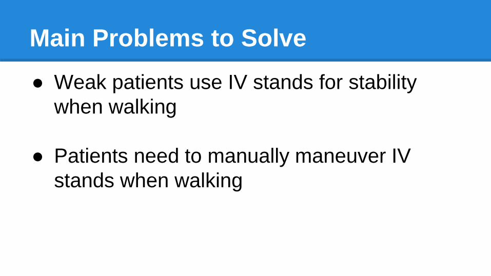
● Weak patients use IV stands for stability
when walking
● Patients need to manually maneuver IV
stands when walking
Main Problems to Solve

Target Patients
● 13 years and older
● Long term stay (more than a week)
● Low traffic areas
● Weak or post-operation patients
o Patients that require assistance to walk without
using an IV stand for stability
o Not recommended for patients who recently had
abdominal surgery
P15073: Autonomous IV Stand

Scenario 1: Patient goes for walkP15073: Autonomous IV Stand
● Detects patient is
mobile.
● Follows at safe
distance.
● Allows patient
access to proper
support.

Scenario 2: Manually Push IV Stand
● Omni wheels lift up
● Nurse maneuvers IV
stand manually
● Allows for flexibility
of the device

Removed

CAD Model
P15073: Autonomous IV Stand

CAD ModelP15073: Autonomous IV Stand
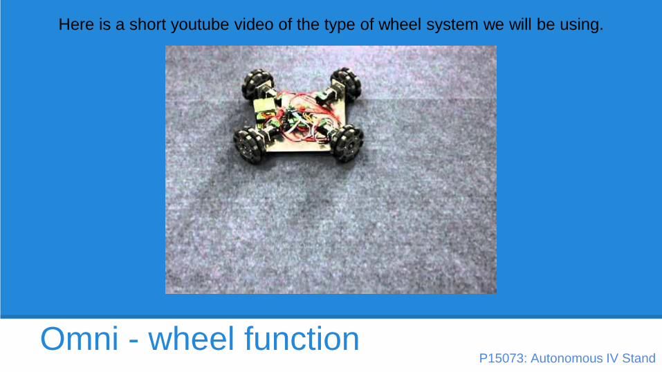
Omni - wheel function
Here is a short youtube video of the type of wheel system we will be using.
P15073: Autonomous IV Stand

Bill of Materials Summary
● 53 items to be purchased: $1458.10
● Total w/ Estimated Shipping Cost: $1654.24
● 10% Contingency: $145.81
● Estimated Overall Cost: $1800.05
● 4 items already purchased through MSDo $422.32

Questions?
P15073: Autonomous IV Stand

Questions for Dr. DeMartino
● What do you need from us for grant
justification?
● Would we continue to purchase parts through
MSD or would we have to use a different
process through the Innovation Center?
P15073: Autonomous IV Stand

SME: Rob Kraynik
Base Machine Suggestion: Weld It● He will do the welding
● Should look aesthetically pleasing
● Will be easier than forming it
Recommended Dimensions● .060” Al
● Use 6/32 or 8/32 screws to attach base in 8 locations
Scheduling● Stop down first week of spring semester
● They will look at amount of work and provide an estimated completion date

Ensure Driving Wheels Make Contact with the Floor

Ping Sensor Placement
14.2 inches apart
~3.8 inches from the front
centered on the base
Max Height (in.)
74.4
Waist Width (0.191H)
14.2

Ping Sensor Placement

Ping Sensor Placement

Prelim.Test Plan - Mechanical
P15073: Autonomous IV Stand
1. Test FEA of UHMW
2. Turn resistance of encoder and potentiometer

Prelim. Test Plan - Electrical
P15073: Autonomous IV Stand
1. Test battery to determine that it provides 24V DC. Test battery with voltage
division circuit to determine the proper voltage and amperage are being
provided to each component.
2. Test motors using power supply.
3. Initial arduino programming and testing with motor shields to determine
functionality and proper outputs to the motors.
4. Initialize communication between arduino and encoders.
5. Initialize communication between arduino and ping sensors.
6. Run independently from laptop.

Prelim. Test Plan - Subsystem
P15073: Autonomous IV Stand
1. Test integration between arduino and motor shields with
actual motors.
2. Test the tether subsystem with arduino logic
3. Test the object detection subsystem with arduino logic.
4. Test motor connector shaft with omni wheels and motors.
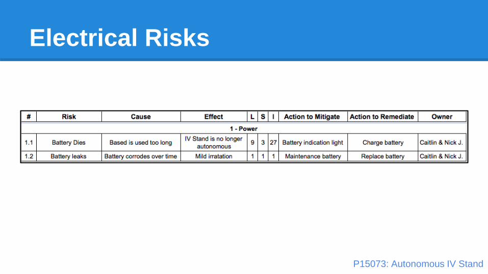
Electrical Risks
P15073: Autonomous IV Stand

Electrical Risks
P15073: Autonomous IV Stand

Electrical Risks
P15073: Autonomous IV Stand

Electrical Risks
P15073: Autonomous IV Stand

MSD II Project Plan

MSD II Project Plan

MSD II Project Plan
Planned Meeting Time: Tuesdays 2:00pm - 3:30pm

Questions?
P15073: Autonomous IV Stand

High Risk Subsystems
● Provide Power
● Maintain Proximity
● Avoid Objects
● Deliver IV Bags
P15073: Autonomous IV Stand

Provide Power
P15073: Autonomous IV Stand

Materials to Provide Power
P15073: Autonomous IV Stand

Power Feasibility Calculations
P15073: Autonomous IV Stand

Maintain Proximity
P15073: Autonomous IV Stand

Materials For Drive Sub-System
P15073: Autonomous IV Stand

Feasibility
P15073: Autonomous IV Stand
● 8” Omni-wheels needed instead of 6”
● Omni-wheels enable us to make quick and
accurate adjustments to direction
● Motor provides torque required to move
stand at specified RPM’s
● Motor will mount to the sides of the base
shell

Feasibility
Aluminum Rod-Al 6061
-High yield strength
-Cost effective
-deflection not an issue
Set screw
-fits our design parameters
P15073: Autonomous IV Stand

Feasibility
Pixy Camera - provides unreliable feedback
Encoder - provide constant feedback
Pixy Camera - needed to be tested to understand its capabilities
Encoder - straight forward implementation
Pixy Camera - patient must wear a vest to determine their location
Encoder - patient must wear a belt to determine their location
Both options include an additional tether attached to the patient
for safety
CMU Pixy Camera vs. Tether with Encoder
P15073: Autonomous IV Stand

Feasibility
CMU Pixy Camera vs. Tether with Encoder
We chose the tether with encoder option to detect the
patient due to its straight forward implementation and
its ability to provide constant feedback on the
patient’s position.
Encoder Potentiometer
P15073: Autonomous IV Stand

Material for Following Sub-System
P15073: Autonomous IV Stand
● The 90 degree angle purchased
from McMaster will be machined for
our purposes.
● The sheet metal parts will be cut on
the waterjet from the aluminum
sheet that is also being used for the
cover on the base.

Lower Assembly
● Will be bolted to the base
● A retractable keychain will also bolt
to the aluminum angle
● The rotary encoder will mount to
the angle with the provided panel
nut

Aluminum Angle Needs Machining
● Machine in RIT shop
● The dimensions of the retractable
spool are not currently known

Upper Assembly
● Will affix to the larger telescoping
tube at a specific height from the
ground
● The tether will feed up from the
lower assembly
● The sheet metal arm provides a
moment to easily turn the
potentiometer

Upper Assembly

Pole Flange
● Will be made on the waterjet along
with the base cover and arm
● Will mount to tapped holes on shaft
collar
● Potentiometer will mount from
bottom with panel nut

Sheet Metal Arm
● Will be made on the waterjet
along with the base cover and
pole flange
● The two ends will be bent to 90
degrees as shown

Standoff needs Machining
● The standoff from McMaster will be
machined down to 6mm in order to fit
with shaft coupler that is attached to
the potentiometer

Avoid Objects
P15073: Autonomous IV Stand

Material to Avoid Objects
● Perform measurements between moving
or stationary objects
● Provides precise, non-contact distance
measurements within a 2 cm to 3 m range
● Burst indicator LED shows measurement
in progress
● Simple pulse-in/pulse-out communication
P15073: Autonomous IV Stand

Deliver IV Bags
P15073: Autonomous IV Stand

Materials to Deliver IV Bags
P15073: Autonomous IV Stand

Medium Risk Subsystems
● Provide Feedback
● Manually Maneuver IV Stand (Raise Omni-
Wheels)
● Keeping the Omni-Wheels on the ground
P15073: Autonomous IV Stand

Omni-Wheel Lifting MechanismP15073: Autonomous IV Stand
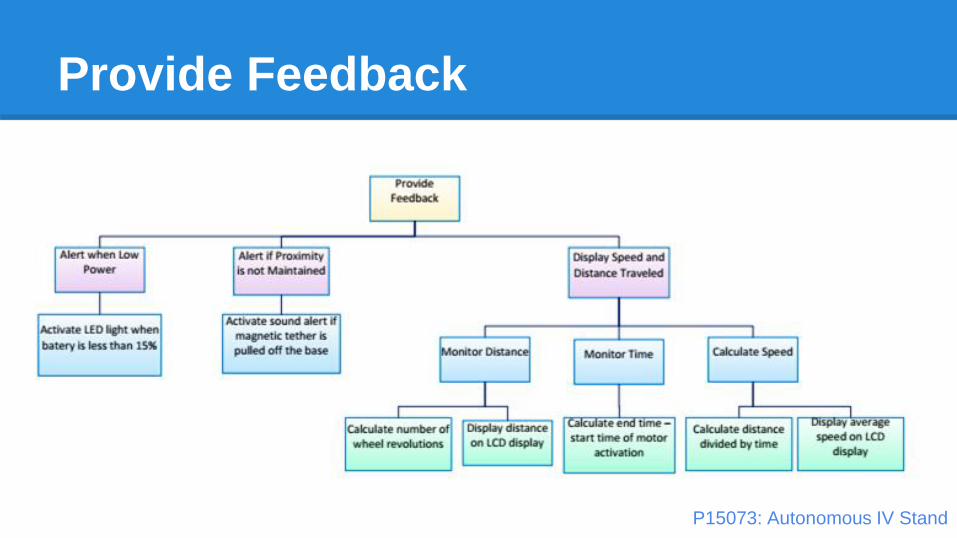
Provide Feedback
P15073: Autonomous IV Stand

Materials for Providing Feedback
P15073: Autonomous IV Stand

Mechanical Drawings
● Baseo Top Shell
o Flat Bottom
● Motor Lift Plate
● Battery Shelf
● Top pole
● Bottom pole
● Wheel Hub and Drive ShaftP15073: Autonomous IV Stand

Base Top

UHMW Bottom

Motor Lift Sheet

Battery Shelf

Top Pole
P15073: Autonomous IV Stand

Bottom Pole
P15073: Autonomous IV Stand

Wheel Hub and Drive Shaft
P15073: Autonomous IV Stand

Electrical Diagrams
P15073: Autonomous IV Stand
All sensors use a
total of 50 Digital
I/O pins and 4
analog pins

LCD screen and Fan

Motor Connection and Sonic Ping

Pseudo Code
P15073: Autonomous IV Stand

Questions?
P15073: Autonomous IV Stand

What We Want From The Audience
Is there anything that we are failing to consider?
Do you see any challenges with our design we have failed
to observe?
P15073: Autonomous IV Stand

Thank You
P15073: Autonomous IV Stand