Embed Size (px)
Citation preview

P13571 D3 VIDEO ANALYTICS: ME Detailed Design Review
ME -1 | D 3 V I D E O A N A L Y T I C S
Table of Contents: 1. Project Overview ME-2
a. Project’s Design Intent ME-2
b. Objectives ME-2
c. The Design So Far ME-2
d. Deliverables ME-2
e. Key Issues and Risks ME-2
2. Customer Needs / Specifications ME-3
3. Updated Risk Assessment ME-4
4. Bill of Materials ME-5-6
5. The Design ME-7-9
a. M12 Lens Configuration ME-7
b. Seals & Gaskets ME-8-9
6. FEA Analysis ME-10-14
a. Thermal Management Analysis ME-10-14
7. Preliminary Test Plans ME-15-26
a. Drop Test ME-15-17
b. Heat Dissipation Test ME-18-19
c. Dust Tight Test ME-20-21
d. Water Spray Test ME-21-24
8. Appendix ME-25-30
a. Schematics ME-25-29
b. References ME-30
c. Manufacturers & Distributors ME-30

P13571 D3 VIDEO ANALYTICS: ME Detailed Design Review
ME -2 | D 3 V I D E O A N A L Y T I C S
Project Overview
Project’s Design Intent The project’s design intent, from a mechanical a perspective, is to
enclose sensitive electric, optical, and mechanical components in a
ruggedized enclosure and maintain ease of assembly. Ruggedized
is defined as water proofed and dust proof, in accordance with the
IP64 standard.
Objectives 1. Design an enclosure within the size constrains of the
customer’s specifications.
2. Design must allow for an operational environment within
the enclosure for all electrical and mechanical components.
3. Design must meet IP64 standards.
4. Enclosure components must be able to withstand high and
low automotive temperatures.
The Design So Far Through multiple discussions with our advisors, both at D3 and RIT,
the design has converged onto a single design, which, as shown by
FEA Analysis, promises to meet the customer’s needs and
specifications.
Deliverables A design with the ability to dissipate the heat generated by
the electrical components.
A design that can withstand impact of a 2 foot drop onto
carpeted flooring.
Ease of assembly.
Key Issues and Risks Insufficient time to meet all customer needs.
Current design fails to meet customer specifications.
Heat dissipated by design is insufficient for high
temperatures.
Unable to withstand impact from 2 foot drop on any
surface.
Design has a high tolerance stack up.
Optical components do not align correctly.
BNC connector is not secured properly.
P13571 D3 VIDEO ANALYTICS: ME Detailed Design Review
ME -3 | D 3 V I D E O A N A L Y T I C S
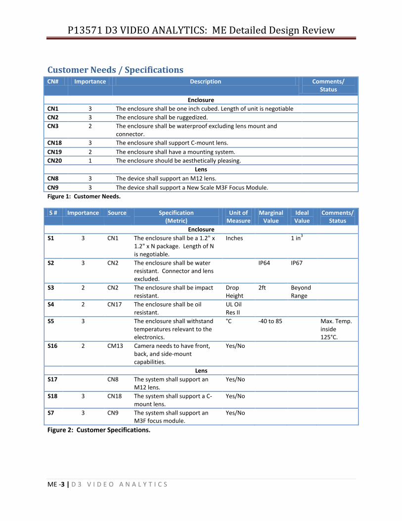
Customer Needs / SpecificationsCN# Importance Description Comments/
Status
Enclosure
CN1 3 The enclosure shall be one inch cubed. Length of unit is negotiable
CN2 3 The enclosure shall be ruggedized.
CN3 2 The enclosure shall be waterproof excluding lens mount and connector.
CN18 3 The enclosure shall support C-mount lens.
CN19 2 The enclosure shall have a mounting system.
CN20 1 The enclosure should be aesthetically pleasing.
Lens
CN8 3 The device shall support an M12 lens.
CN9 3 The device shall support a New Scale M3F Focus Module.
Figure 1: Customer Needs.
S # Importance Source Specification (Metric)
Unit of Measure
Marginal Value
Ideal Value
Comments/ Status
Enclosure
S1 3 CN1 The enclosure shall be a 1.2" x 1.2" x N package. Length of N is negotiable.
Inches 1 in3
S2 3 CN2 The enclosure shall be water resistant. Connector and lens excluded.
IP64 IP67
S3 2 CN2 The enclosure shall be impact resistant.
Drop Height
2ft Beyond Range
S4 2 CN17 The enclosure shall be oil resistant.
UL Oil Res II
S5 3 The enclosure shall withstand temperatures relevant to the electronics.
°C -40 to 85 Max. Temp. inside 125°C.
S16 2 CM13 Camera needs to have front, back, and side-mount capabilities.
Yes/No
Lens
S17 CN8 The system shall support an M12 lens.
Yes/No
S18 3 CN18 The system shall support a C-mount lens.
Yes/No
S7 3 CN9 The system shall support an M3F focus module.
Yes/No
Figure 2: Customer Specifications.

P13571 D3 VIDEO ANALYTICS: ME Detailed Design Review
ME -4 | D 3 V I D E O A N A L Y T I C S
Updated Risk Assessment ID Risk Item Effects Cause L S I Actions to
Minimize Risk Owner
1 Tolerance Stack Up
Optical Components
are misaligned
Incorrect calculations and
machining of parts
1 3 3 Multiple checks on calculations and drawing specs.
Cameron and Jose
2 IP64 Limited ingress of dust and
water
Push for smaller O-rings
1 3 3 Search for extra room for
components
Jose
3 Shifting Connector
Tension on PCBs and on
Optics
Connector not held in place properly
2 2 4 Remove connector from PCBs in the
future
Cameron
4 Heat Dissipation
Unable to effectively
dissipate heat in a high
temperature environment
Design and material limitations;
Compromises made for electrical and
optical components
1 3 3 Heat dissipation simulations; Heat
sinks
Cameron
5 Impact Enclosure does not meet
rugged requirement
Design and material limitations
2 3 6 Drop test simulations
Jose
6 Drop Test Simulation
Unable to claim design as
ruggedized
Simulation software and hardware
limitation; limited understanding of
software
3 3 9 Alternative software or
techniques to simulate drop test
Jose
7 Bill of Materials
Delay on ordering of
parts
Limited information on parts and prices
1 2 2 Direct contact with manufactures and
distributers
Cameron and Jose
Figure 3: Up-to-date Risk Assessment

P13571 D3 VIDEO ANALYTICS: ME Detailed Design Review
ME -5 | D 3 V I D E O A N A L Y T I C S
Bill of Materials
# Supplier Material Part Number
Qty. Price Per Unit
Total Part
Products to be Purchased
1 McMaster Al 6061 Alloy, 1.5" X 1.5" X 12"
9008K61 1 $20.07 $20.07 Lens Cover
2 McMaster Al 6061 Alloy, 1.5" X 1.5" X 12"
9008K61 0 $20.07 $0.00 C-Mount Cover
3 McMaster Al 6061 Alloy, 1.5" X 1.5" X 12"
9008K61 0 $20.07 $0.00 Sensor Mount
4 McMaster Al 6061 Alloy, 1.5" X 1.5" X 12"
9008K61 0 $20.07 $0.00 M12 Sensor Mount
5 McMaster Al 6061 Alloy, 1.5" X 1.5" X 12"
9008K61 0 $20.07 $0.00 Housing Rear
6 McMaster Metric Dowel Pins, M1.5 Dia X 8
93600A056 2 $9.20 (Pkg. of
50)
Dowel

P13571 D3 VIDEO ANALYTICS: ME Detailed Design Review
ME -6 | D 3 V I D E O A N A L Y T I C S
7 McMaster Metric Pan Head Machine Screws, M2 X 0.4 X 8 (M2--#1 Drive)
90116A015 1 $7.67 (Pkg. of
100)
M2 X 0.4 X 8 Pan Head
8 McMaster Metric Pan Head Machine Screws, M2 X 0.4 X 16 (M2--#1 Drive)
90116A025 2 $10.95 (Pkg. of
100)
M2 X 0.4 X 16 Pan Head
9 McMaster Metric Flat Head Philips Machine Screws, M2 X 0.4 X 20 (M2--#0 Drive)
92010A010 4 $7.71 (Pkg. of
100)
M2 X 0.4 X 20 Flat Head
10 McMaster Ultra-Conductive Copper (Alloy 101) 6” X
6” X 0.032”
89675K11 1 $12.85 $12.85 Cold Fingers
11 McMaster Aluminum Tubing, 0.014” OD X 0.097” ID
X 1’
7237K14 1 $2.12 (Pkg. of
3)
PCB Spacers
12 Grainger Helicoil Insert, 304SS, M2 X 0.4
4DAG5 7 $87.80 (Pkg. of
100)
Helicoil Inserts
13 Gallagher Seals
Parker O-Ring, 28.30mm ID X 1.78mm
W
2-024-LM159-70
1 $0.79 (Pkg. of
100)
O-Ring Housing Gasket
14 Gallagher Seals
Parker O-Ring, 25.07mm ID X 0.79mm
W
5-139-LM159-70
2 $2.11 (Pkg. of
100)
Lens Gasket
15 Gallagher Seals
Parker O-Ring, 4.47mm ID X 1.78MM W
2-008-LM159-70
1 $0.75 (Pkg. of
100)
Connector Gasket
16 Thorlabs Mounted 400 nm LP Filter, SM1
FGL280M 1 $46.80 $46.80 Lens Filter
17 Parker THERMATTACH Double-Sided Themal
Tape
T418 1 Thermal Tape
18 Parker CHO-THERM Insulator Pad
T500 1 Thermal Pad
# Supplier Material Part Number
Qty. Price Per Unit
Total Part
Products Possibly Provided by D3
19 Digi-Key Newscale M3-F Focus Module
DK-M3F-1.8-TRK-1.5-S-ND
1 $702.00 $702.00 M3-F Focus Module
20 Sunex M12 Lens 1 $49.00 $49.00 M12 Lens
Total 27 $959.52

P13571 D3 VIDEO ANALYTICS: ME Detailed Design Review
ME -7 | D 3 V I D E O A N A L Y T I C S
The Design
M12 Lens Configuration
Exploded View
Section View

P13571 D3 VIDEO ANALYTICS: ME Detailed Design Review
ME -8 | D 3 V I D E O A N A L Y T I C S
Seals & Gaskets
Front/Rear Seal
The groove and o-ring are designed to provide a lock-tight seal for an external pressure of ranging from
0-690kPa, which is higher than IP64 requirements. The design of the groove is based of a research
paper, Stresses and Deformation of Compressed Elastomic O-ring Seals by Itzhak Green and Capel
English, which describes equations for solving groove width and depth based on the peak contact stress
and the elastic modulus of the o-ring. Due to size constrains, the groove width was kept equivalent to
the o-ring wire diameter. The equations used are as follows:
Loading Case c d e
Restrained Axial Primary Wall 3.8295 -23.0013 82.6963
Restrained Axial Lateral Wall 2.6584 -16.1793 71.5999
( )
( )
( )
13
13

P13571 D3 VIDEO ANALYTICS: ME Detailed Design Review
ME -9 | D 3 V I D E O A N A L Y T I C S
( ( ) )
Nomenclature
d O-ring Diameter
E O-ring Elastic Modulus
Smax Peak Contact Stress
δ Normalized Squeeze
δij Equivalent Normalized Squeeze
x Displacement
h Groove Depth
l Groove Width
Filter Seal
Connector Seal
14
14
15

P13571 D3 VIDEO ANALYTICS: ME Detailed Design Review
ME -10 | D 3 V I D E O A N A L Y T I C S
FEA Analysis
Thermal Management Analysis
As the customer the needs document depicts, the assembly must withstand
temperatures ranging from -40 deg C to 105 deg C. During the designing phase, the
temperature of 125 deg C was used as the high end thermal limit. In an effort to dissipate the
heat generated to the outside, several factors were taken into account.
Conduction (PCB to Outside Surface):
Thermal Pads (k=5 W/m^2*K)
Cold Finger
Assembly
Material Selection
Al 6061 (k=240 W/m^2*K)
Copper (k=360 W/m^2*K)
Convection
Maximizing Surface Area
Heat Sink
Convection Coefficient Analysis
Estimated k values W/m*K
The cold finger was implemented to decrease the thermal
resistance from the FPGA to the housing by creating a low
resistance pathway for heat flow. Several different cold finger
geometries were tested. After several trails, three large factors
influencing the FPGA temperature are the cold finger material,
cross section shape, and pathway distance. Copper was material of
choice having a high conductance coeffient of about 360 W/m K
compared to 50 W/m K for sheet metal. The geometry also has a
large impact, the idea of cold fingers is to transfer energy the
fastest and possible and since heat flux depends on the thermal
resistance, the larger the scross sectional area of the sheet, the
more can pass.
The basic equation of conductance:
Resistance’[R’] =Distance[L]/Coefficient of Conductivity [K]*Area [A]
Acrylic 0.2
Aluminum 240
Apple (85.6% moisture) 0.39
Brick dense 0.17
Brickwork, common 0.02
Copper 360
Carbon Steel 54
Epoxy 0.35
Glass 1.05
Gold 310
Iron 80
Iron, wrought 59
Iron, cast 55
Magnesium 156
Polypropylene 0.1 - 0.22
Polystyrene, expanded 0.03
PTFE 0.25
PVC 0.19
Pyrex glass 1.005
Steel, Carbon 1% 43
Stainless Steel 14
Wood 0.12

P13571 D3 VIDEO ANALYTICS: ME Detailed Design Review
ME -11 | D 3 V I D E O A N A L Y T I C S
Figure 1: Comparison of Cold Finger Materials, Models from 2/1/1
F
Figure2: Cold Finger Geometry Figure3: Iso-Contours, 1 Watt at FPGA
By implementing a three prong design, cross sectional area is tripled, reducing the thermal
resistance of the cold finger by a factor of three.
P13571 D3 VIDEO ANALYTICS: ME Detailed Design Review
ME -12 | D 3 V I D E O A N A L Y T I C S
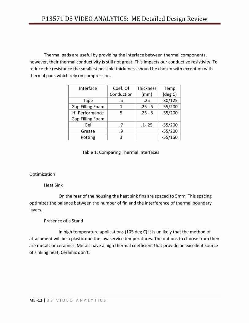
Thermal pads are useful by providing the interface between thermal components,
however, their thermal conductivity is still not great. This impacts our conductive resistivity. To
reduce the resistance the smallest possible thickeness should be chosen with exception with
thermal pads which rely on compression.
Table 1: Comparing Thermal Interfaces
Optimization
Heat Sink
On the rear of the housing the heat sink fins are spaced to 5mm. This spacing
optimizes the balance between the number of fin and the interference of thermal boundary
layers.
Presence of a Stand
In high temperature applications (105 deg C) it is unlikely that the method of
attachment will be a plastic due the low service temperatures. The options to choose from then
are metals or ceramics. Metals have a high thermal coefficient that provide an excellent source
of sinking heat, Ceramic don’t.
Interface Coef. Of Conduction
Thickness (mm)
Temp (deg C)
Tape .5 .25 -30/125
Gap Filling Foam 1 .25 - 5 -55/200
Hi-Performance Gap Filling Foam
5 .25 - 5 -55/200
Gel .7 .1-.25 -55/200
Grease .9 -55/200
Potting 3 -55/150

P13571 D3 VIDEO ANALYTICS: ME Detailed Design Review
ME -13 | D 3 V I D E O A N A L Y T I C S
Figure 4: Camera Housing on Stainless Steel Plate with Bosses 1.8 Watts generated
Figure 5: Camera Housing Resting on Ceramic Plate with 1 Watt of generation

P13571 D3 VIDEO ANALYTICS: ME Detailed Design Review
ME -14 | D 3 V I D E O A N A L Y T I C S
Thermal Results
Maximum Wattage Produced while maintaining 125 deg C at 105 deg C ambient:
Convection only
M12 and M3F Assembly: .98W
C-Mount: .89 W
Conduction and Convection:
Stainless Steel (k=14 W/mK)
M12 and M3F Assembly: 2.5W
C-Mount: 2.1 W
Ceramic (k=.25 W/mK)
M12 and M3F Assembly: 1.4W
C-Mount: 1.2 W
P13571 D3 VIDEO ANALYTICS: ME Detailed Design Review
ME -15 | D 3 V I D E O A N A L Y T I C S
Preliminary Test Plan
Drop Test This test is designed to test the durability of the enclosure against impact. The test shall consist of a
simulated drop onto carpeted flooring using a Precision Drop Tester from various heights (maximum of
2ft). All tests will have an initial velocity of 0m/s. Drop impact conditions will include: surface-to-
surface, edge-to-surface, and vertex-to-surface.
Start Date: Finish Date:
Engineer conducting test:
Assistant:
Conditions:
Ambient Temperature:
Other:
Equipment:
Precision Drop Tester
Observations:
Visual defects before test?: □Yes □No
If yes, explain:
Tests:
1. Surface-to-Surface Test
a. Drop Height:
i. Results: □Major Defects □Minor Defects
ii. Comments:
b. Drop Height:
i. Results: □Major Defects □Minor Defects
ii. Comments:

P13571 D3 VIDEO ANALYTICS: ME Detailed Design Review
ME -16 | D 3 V I D E O A N A L Y T I C S
c. Drop Height:
i. Results: □Major Defects □Minor Defects
ii. Comments:
d. Drop Height:
i. Results: □Major Defects □Minor Defects
ii. Comments:
2. Edge-to-Surface Test
a. Drop Height:
i. Results: □Major Defects □Minor Defects
ii. Comments:
b. Drop Height:
i. Results: □Major Defects □Minor Defects
ii. Comments:
c. Drop Height:
i. Results: □Major Defects □Minor Defects
ii. Comments:
d. Drop Height:
i. Results: □Major Defects □Minor Defects
ii. Comments:
3. Vertex-to-Surface Test
a. Drop Height:
i. Results: □Major Defects □Minor Defects
ii. Comments:
b. Drop Height:
i. Results: □Major Defects □Minor Defects
ii. Comments:

P13571 D3 VIDEO ANALYTICS: ME Detailed Design Review
ME -17 | D 3 V I D E O A N A L Y T I C S
c. Drop Height:
i. Results: □Major Defects □Minor Defects
ii. Comments:
d. Drop Height:
i. Results: □Major Defects □Minor Defects
ii. Comments:

P13571 D3 VIDEO ANALYTICS: ME Detailed Design Review
ME -18 | D 3 V I D E O A N A L Y T I C S
Heat Dissipation Test This test consists of mounting a PCB with a single resistor, which is capable of dissipating a certain
amount of heat, into the enclosure to tests the enclosure’s capabilities to dissipate heat under certain
conditions. The resistor will produce 1 to 2 Watts of heat to simulate the heat produced by the major
electrical components, which the enclosure must dissipate. The conditions under which the test will be
conducted are: high temperatures (105°C), low temperatures (-40°C), and room temperature (20°C). An
Omega Thermocouple Data Logger, or similar, will be used to record the temperatures inside the
enclosure and on its outside surface.
Start Date: Finish Date:
Engineer conducting test:
Assistant:
Equipment:
Omega Thermocouple Data Logger
If other, please specify:
Tests:
1. High Temperature Test
a. Resistor (W):
i. Ambient Temperature:
ii. Temperature Inside Enclosure:
iii. Temperature On Surface of Enclosure:
iv. Comments:
b. Resistor (W):
i. Ambient Temperature:
ii. Temperature Inside Enclosure:
iii. Temperature On Surface of Enclosure:
iv. Comments:
2. Low Temperature Test
a. Resistor (W):
i. Ambient Temperature:
ii. Temperature Inside Enclosure:
iii. Temperature On Surface of Enclosure:
iv. Comments:
P13571 D3 VIDEO ANALYTICS: ME Detailed Design Review
ME -19 | D 3 V I D E O A N A L Y T I C S
b. Resistor (W):
i. Ambient Temperature:
ii. Temperature Inside Enclosure:
iii. Temperature On Surface of Enclosure:
iv. Comments:
3. Room Temperature Test
a. Resistor (W):
i. Ambient Temperature:
ii. Temperature Inside Enclosure:
iii. Temperature On Surface of Enclosure:
iv. Comments:
b. Resistor (W):
i. Ambient Temperature:
ii. Temperature Inside Enclosure:
iii. Temperature On Surface of Enclosure:
iv. Comments:

P13571 D3 VIDEO ANALYTICS: ME Detailed Design Review
ME -20 | D 3 V I D E O A N A L Y T I C S
Dust Tight Test This is a test on the enclosure’s and seal’s capability to completely protect the enclosed components
from the ingress of dust; in other words, it’s ability to meet the Ingress Protection Rating 64 (IP64) for
solid materials. The test will be conducted by submerging the sealed enclosure in shallow pool of water.
The shallow pool of water is defined as having a depth 10mm greater than the height of the enclosure
(40.5mm total depth). All components will be removed from within the enclosure before the beginning
of the test and the BNC connector mounting hole will be sealed. At the beginning of the test, the
enclosure should be placed securely at the bottom of the water tub. When submerged, the enclosure
should prevent the formation of air bubbles near the seals for at least 30 minutes; the formation of air
bubble around the seals before 30 minutes will be taken as proof that the seals are ineffective at
protecting the components from dust.
Start Date: Finish Date:
Engineer conducting test:
Assistant:
Conditions:
Ambient Temperature:
Humidity:
Other:
Observations:
Visual defects before test?: □Yes □No
If yes, explain:
Equipment:
Large Water Tub
If other, please specify:
Test:
1. Submerge Test
a. Water Depth:
b. Water Temperature:
c. Start time of test:
i. Formation of bubbles at Front/Rear Seal? □Yes □No
If yes, specify time and comment:
P13571 D3 VIDEO ANALYTICS: ME Detailed Design Review
ME -21 | D 3 V I D E O A N A L Y T I C S
ii. Formation of bubbles at Filter Seal? □Yes □No
If yes, specify time and comment:
iii. Formation of bubbles at Connector Seal? □Yes □No
If yes, specify time and comment:

P13571 D3 VIDEO ANALYTICS: ME Detailed Design Review
ME -22 | D 3 V I D E O A N A L Y T I C S
Water Spray Test This test calls for the enclosure to be subjected to a water spray from all directions. The components
within the enclosure must be completely protected from the ingress of water for this test to be
successful, which is a higher requirement than the Ingress Protection Rating 64 (IP64); IP64 permits a
limited ingress of water, which is unfavorable for our device. In accordance with IP64, the enclosure will
be subjected to a volume of water of 10 LPM at a pressure of 100 kPa from all directions for 5 minutes
each. Additionally, the water nozzle used in the test will be held in place at a distance of 3m. At the end
of the test, the enclosure will be inspected and then dried before the start of the next test. If any water
or evidence of moisture is found within the enclosure during inspection, that test has failed and the
overall test has failed.
Start Date: Finish Date:
Engineer conducting test:
Assistant:
Conditions:
Ambient Temperature:
Humidity:
Other:
Observations:
Visual defects before test?: □Yes □No
If yes, explain:
Equipment:
Water Nozzle
If other, please specify:
Test:
1. Front Surface Test
a. Any parts replace before test? □Yes □No
If yes, which and why:
b. Flow Rate:
c. Pressure:
d. Start Time: End Time:

P13571 D3 VIDEO ANALYTICS: ME Detailed Design Review
ME -23 | D 3 V I D E O A N A L Y T I C S
e. Water/Moisture in enclosure? □Yes □No
If yes, describe:
2. Back Surface Test
a. Any parts replace before test? □Yes □No
If yes, which and why:
b. Flow Rate:
c. Pressure:
d. Start Time: End Time:
e. Water/Moisture in enclosure? □Yes □No
If yes, describe:
3. Right Surface Test
a. Any parts replace before test? □Yes □No
If yes, which and why:
b. Flow Rate:
c. Pressure:
d. Start Time: End Time:
e. Water/Moisture in enclosure? □Yes □No
If yes, describe:
4. Left Surface Test
a. Any parts replace before test? □Yes □No
If yes, which and why:
b. Flow Rate:
c. Pressure:
d. Start Time: End Time:
e. Water/Moisture in enclosure? □Yes □No
If yes, describe:
5. Top Surface Test
a. Any parts replace before test? □Yes □No
If yes, which and why:
b. Flow Rate:

P13571 D3 VIDEO ANALYTICS: ME Detailed Design Review
ME -24 | D 3 V I D E O A N A L Y T I C S
c. Pressure:
d. Start Time: End Time:
e. Water/Moisture in enclosure? □Yes □No
If yes, describe:
6. Bottom Surface Test
a. Any parts replace before test? □Yes □No
If yes, which and why:
b. Flow Rate:
c. Pressure:
d. Start Time: End Time:
e. Water/Moisture in enclosure? □Yes □No
If yes, describe:
P13571 D3 VIDEO ANALYTICS: ME Detailed Design Review
ME -25 | D 3 V I D E O A N A L Y T I C S
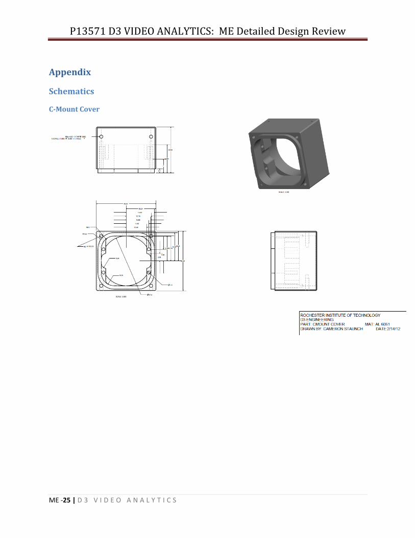
Appendix
Schematics
C-Mount Cover

P13571 D3 VIDEO ANALYTICS: ME Detailed Design Review
ME -26 | D 3 V I D E O A N A L Y T I C S
Lens Cover (M12 and M3-F)

P13571 D3 VIDEO ANALYTICS: ME Detailed Design Review
ME -27 | D 3 V I D E O A N A L Y T I C S
Housing Rear Cover

P13571 D3 VIDEO ANALYTICS: ME Detailed Design Review
ME -28 | D 3 V I D E O A N A L Y T I C S
M12 Sensor Mount

P13571 D3 VIDEO ANALYTICS: ME Detailed Design Review
ME -29 | D 3 V I D E O A N A L Y T I C S
Sensor Mount

P13571 D3 VIDEO ANALYTICS: ME Detailed Design Review
ME -30 | D 3 V I D E O A N A L Y T I C S
References STRESS AND DEFORMATION OF COMPRESSED ELATOMERIC O-
RING SEALS. Green, Itzhak and English, Capel. 14th
International Conference on Fluid Sealing, Firenze, Italy, 6-
8 April 1994. Organized by BHRGroup Limited, Cranfield,
Bedford, MK43 0AJ, UK.
Manufacturers & Distributors Digi-Key Corp. www.digikey.com
Gallagher Fluid Seals, Inc. www.gallagherseals.com
Grainger www.grainger.com
McMaster-Carr www.mcmaster.com
Parker Hannifin Corp. www.parker.com
Thorlabs www.thorlabs.us
Sunex Inc. www.optics-online.com