Embed Size (px)
Citation preview
The CubeSat Program California Polytechnic State University – San Luis Obispo, CA 93407
Poly Picosatellite Orbital Deployer Mk. III Rev. E User Guide
(CP-PPODUG-1.0-1)
Document Classification
X Public Domain ITAR Controlled Internal Only
P-POD Mk. III Rev. E User Guide The CubeSat Program, Cal Poly SLO
Page 2
CHANGE HISTORY LOG
Effective Date Release Author Description of Changes
8/2/07 0.0 W. Lan Preliminary Version
1/15/10 0.8 R. Munakata Launch Vehicle Planner’s Guide
5/7/10 0.9 R. Nugent Updated text, figures, and tables.
3/4/14 1.0 D. Pignatelli Updated for P-POD Mk. III Rev. E
P-POD Mk. III Rev. E User Guide The CubeSat Program, Cal Poly SLO
Page 3
Preface This P-POD User’s Guide is provided to familiarize potential launch providers with interfaces of the Poly Picosatellite Orbital Deployer (P-POD) system. All data provided herein is for reference purposes only and should not be used for mission specific analyses. Detailed analyses will be performed based on the requirements and characteristics of each specific mission. This document will be revised periodically to incorporate the latest information. Please visit our website to ensure this copy of the document is the latest version. Readers are urged to contact the CubeSat Program at California Polytechnic State University with comments or requests for clarification of any information in this document. CubeSat Program California Polytechnic State University San Luis Obispo, CA 93407 Phone: (805) 756-5165 E-mail: [email protected] Website: www.cubesat.org
P-POD Mk. III Rev. E User Guide The CubeSat Program, Cal Poly SLO
Page 4
TABLE OF CONTENTS 1. Introduction ............................................................................................................................. 7
1.1 Overview ............................................................................................................................ 7 1.2 P-POD Mission Objectives ................................................................................................ 7 1.3 History and Flight Heritage ................................................................................................ 8
2. P-POD Features ........................................................................................................................ 9 2.1 P-POD Coordinate System ................................................................................................. 9 2.2 P-POD Mechanical Features ............................................................................................ 10
2.2.1 P-POD Static Envelopes ............................................................................................ 10 2.2.1.1 P-POD Pre-Deployment Static Envelope ............................................................... 10 2.2.1.2 P-POD Post-Deployment Static Envelope ............................................................. 10 2.2.2 P-POD Mechanical Interface .................................................................................... 10 2.2.3 P-POD Material and Coatings ................................................................................... 11 2.2.4 Access Ports .............................................................................................................. 11 2.2.5 Deployment Velocity ................................................................................................ 11 2.2.6 Switch Guide ............................................................................................................. 11 2.2.7 Door Stopper ............................................................................................................. 11
2.3 Mass Properties and Modal Characteristics ..................................................................... 11 2.3.1 P-POD Mass Properties ............................................................................................. 11 2.3.2 P-POD First Natural Frequency ................................................................................ 12
2.4 Electrical Features ............................................................................................................ 12 2.4.1 Electrical Interface .................................................................................................... 13 2.4.2 P-POD Door Release Mechanism ............................................................................. 13 2.4.3 P-POD Door Status Sensor ....................................................................................... 14 2.4.4 Grounding .................................................................................................................. 14
3. Contacts ................................................................................................................................. 14
P-POD Mk. III Rev. E User Guide The CubeSat Program, Cal Poly SLO
Page 5
LIST OF FIGURES
Figure 1: Six CubeSats and their deployment systems ................................................................... 7 Figure 2: P-POD Mk. I (left) and P-POD Mk. II (right) ................................................................. 8 Figure 3: Alodined P-POD Mk. III Rev. E ..................................................................................... 8 Figure 4: P-POD Mk. III Rev. E Coordinate System ...................................................................... 9 Figure 5: Main P-POD Features .................................................................................................... 10 Figure 6: P-POD Electrical Components ...................................................................................... 12 Figure 7: Example of P-POD Electrical Interface ......................................................................... 13
LIST OF TABLES
Table 1: P-POD Flight Heritage Summary ..................................................................................... 9 Table 2: P-POD Mk. III Rev. E Mass Properties .......................................................................... 12 Table 3: P-POD Release Mechanism Interface ............................................................................. 13
P-POD Mk. III Rev. E User Guide The CubeSat Program, Cal Poly SLO
Page 6
List of Acronyms Cal Poly California Polytechnic State University, San Luis Obispo
CDS CubeSat Design Specification
ELaNa Education Launch of Nanosatellites
ESA European Space Agency
kg Kilogram
LV Launch Vehicle
Mk. Mark
mm Millimeters
NASA National Aeronautics and Space Administration
P-POD Poly Picosatellite Orbital Deployer
Rev. Revision
SLO San Luis Obispo
STD Standard
UG User Guide
P-POD Mk. III Rev. E User Guide The CubeSat Program, Cal Poly SLO
Page 7
1. Introduction
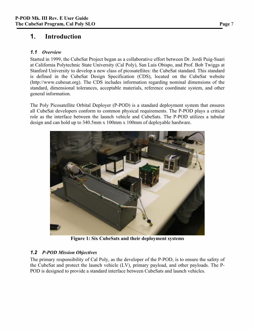
1.1 Overview Started in 1999, the CubeSat Project began as a collaborative effort between Dr. Jordi Puig-Suari at California Polytechnic State University (Cal Poly), San Luis Obispo, and Prof. Bob Twiggs at Stanford University to develop a new class of picosatellites: the CubeSat standard. This standard is defined in the CubeSat Design Specification (CDS), located on the CubeSat website (http://www.cubesat.org). The CDS includes information regarding nominal dimensions of the standard, dimensional tolerances, acceptable materials, reference coordinate system, and other general information. The Poly Picosatellite Orbital Deployer (P-POD) is a standard deployment system that ensures all CubeSat developers conform to common physical requirements. The P-POD plays a critical role as the interface between the launch vehicle and CubeSats. The P-POD utilizes a tubular design and can hold up to 340.5mm x 100mm x 100mm of deployable hardware.
Figure 1: Six CubeSats and their deployment systems
1.2 P-POD Mission Objectives The primary responsibility of Cal Poly, as the developer of the P-POD, is to ensure the safety of the CubeSat and protect the launch vehicle (LV), primary payload, and other payloads. The P-POD is designed to provide a standard interface between CubeSats and launch vehicles.
P-POD Mk. III Rev. E User Guide The CubeSat Program, Cal Poly SLO
Page 8
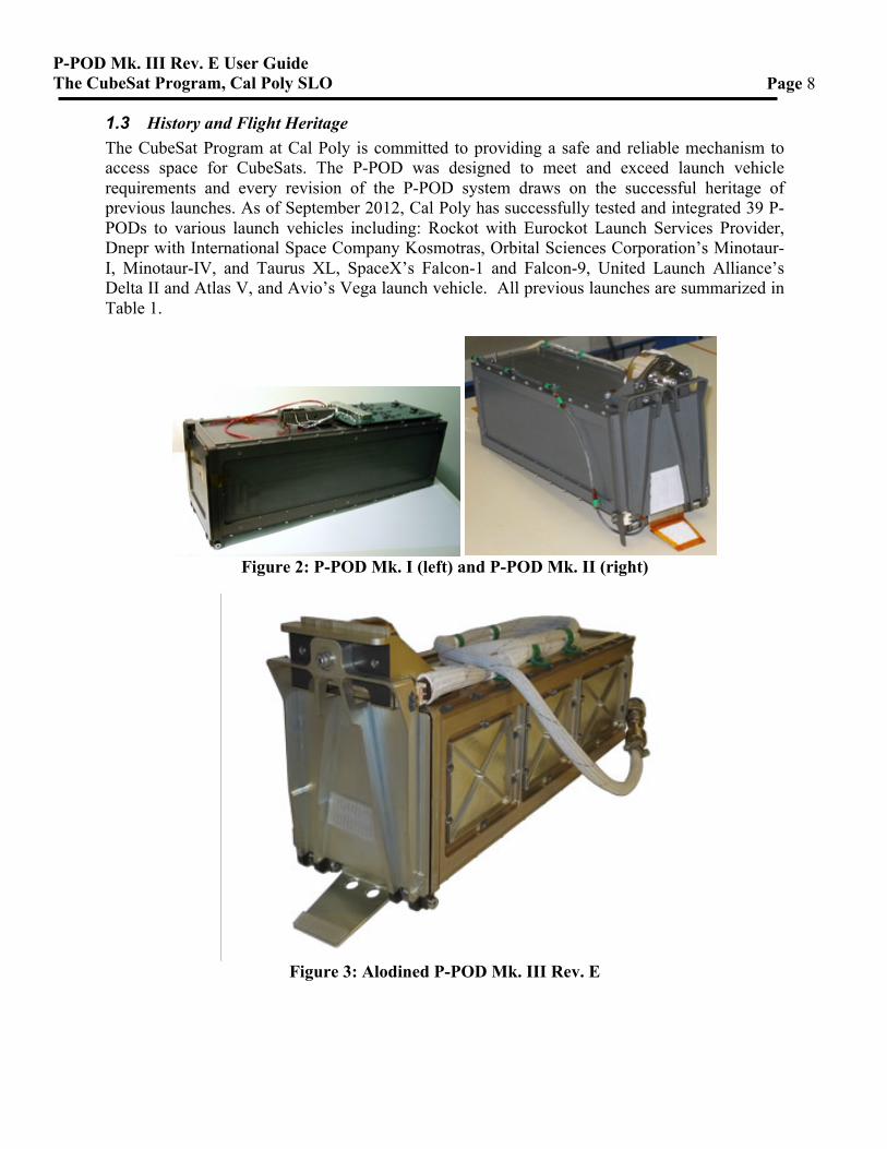
1.3 History and Flight Heritage The CubeSat Program at Cal Poly is committed to providing a safe and reliable mechanism to access space for CubeSats. The P-POD was designed to meet and exceed launch vehicle requirements and every revision of the P-POD system draws on the successful heritage of previous launches. As of September 2012, Cal Poly has successfully tested and integrated 39 P-PODs to various launch vehicles including: Rockot with Eurockot Launch Services Provider, Dnepr with International Space Company Kosmotras, Orbital Sciences Corporation’s Minotaur-I, Minotaur-IV, and Taurus XL, SpaceX’s Falcon-1 and Falcon-9, United Launch Alliance’s Delta II and Atlas V, and Avio’s Vega launch vehicle. All previous launches are summarized in Table 1.
Figure 2: P-POD Mk. I (left) and P-POD Mk. II (right)
Figure 3: Alodined P-POD Mk. III Rev. E
P-POD Mk. III Rev. E User Guide The CubeSat Program, Cal Poly SLO
Page 9
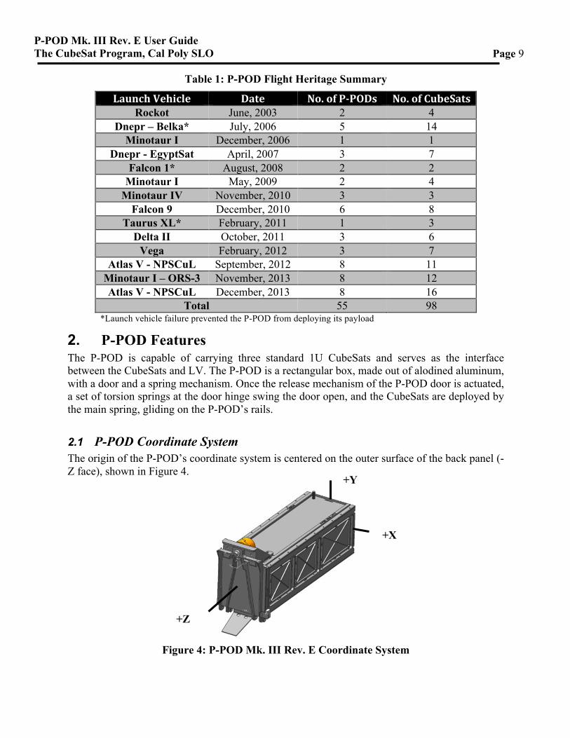
Table 1: P-POD Flight Heritage Summary
Launch Vehicle Date No. of P-‐PODs No. of CubeSats Rockot June, 2003 2 4
Dnepr – Belka* July, 2006 5 14 Minotaur I December, 2006 1 1
Dnepr - EgyptSat April, 2007 3 7 Falcon 1* August, 2008 2 2
Minotaur I May, 2009 2 4 Minotaur IV November, 2010 3 3
Falcon 9 December, 2010 6 8 Taurus XL* February, 2011 1 3
Delta II October, 2011 3 6 Vega February, 2012 3 7
Atlas V - NPSCuL September, 2012 8 11 Minotaur I – ORS-3 November, 2013 8 12 Atlas V - NPSCuL December, 2013 8 16
Total 55 98 *Launch vehicle failure prevented the P-POD from deploying its payload
2. P-POD Features The P-POD is capable of carrying three standard 1U CubeSats and serves as the interface between the CubeSats and LV. The P-POD is a rectangular box, made out of alodined aluminum, with a door and a spring mechanism. Once the release mechanism of the P-POD door is actuated, a set of torsion springs at the door hinge swing the door open, and the CubeSats are deployed by the main spring, gliding on the P-POD’s rails.
2.1 P-POD Coordinate System The origin of the P-POD’s coordinate system is centered on the outer surface of the back panel (-Z face), shown in Figure 4.
Figure 4: P-POD Mk. III Rev. E Coordinate System
+Y
+X
+Z
P-POD Mk. III Rev. E User Guide The CubeSat Program, Cal Poly SLO
Page 10
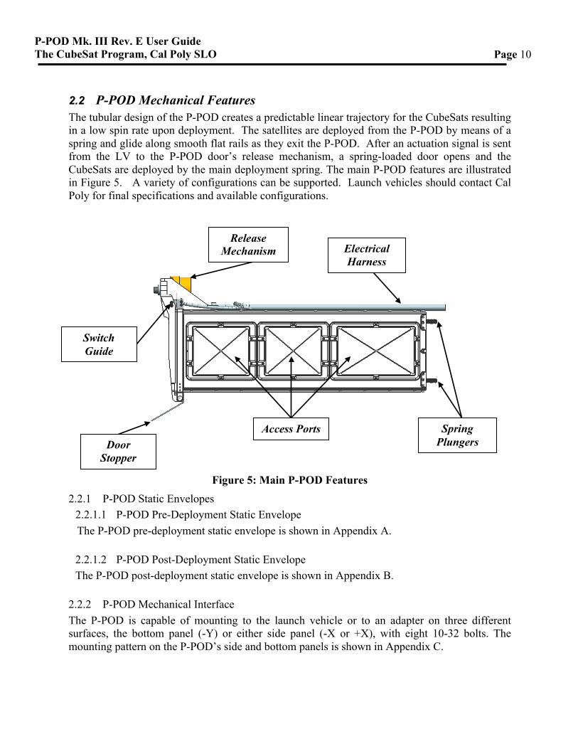
2.2 P-POD Mechanical Features The tubular design of the P-POD creates a predictable linear trajectory for the CubeSats resulting in a low spin rate upon deployment. The satellites are deployed from the P-POD by means of a spring and glide along smooth flat rails as they exit the P-POD. After an actuation signal is sent from the LV to the P-POD door’s release mechanism, a spring-loaded door opens and the CubeSats are deployed by the main deployment spring. The main P-POD features are illustrated in Figure 5. A variety of configurations can be supported. Launch vehicles should contact Cal Poly for final specifications and available configurations.
Figure 5: Main P-POD Features
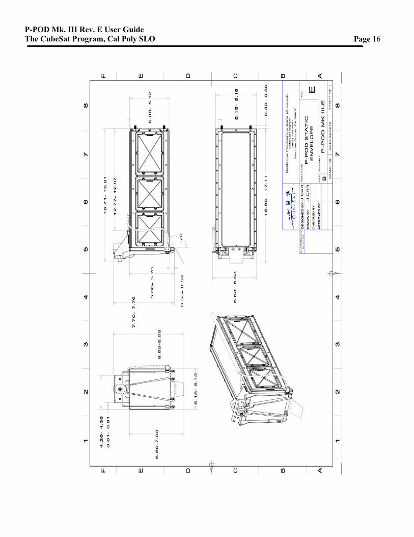
2.2.1 P-POD Static Envelopes 2.2.1.1 P-POD Pre-Deployment Static Envelope The P-POD pre-deployment static envelope is shown in Appendix A.
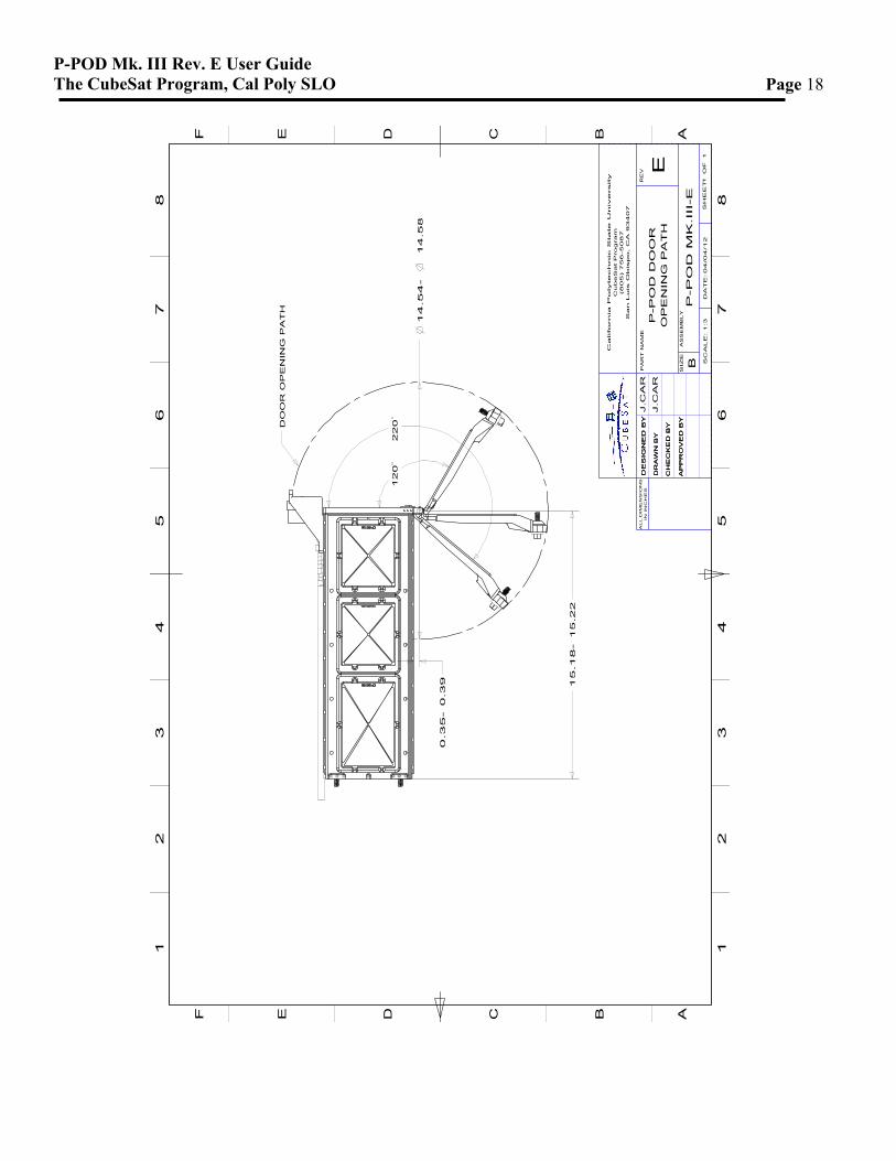
2.2.1.2 P-POD Post-Deployment Static Envelope The P-POD post-deployment static envelope is shown in Appendix B.
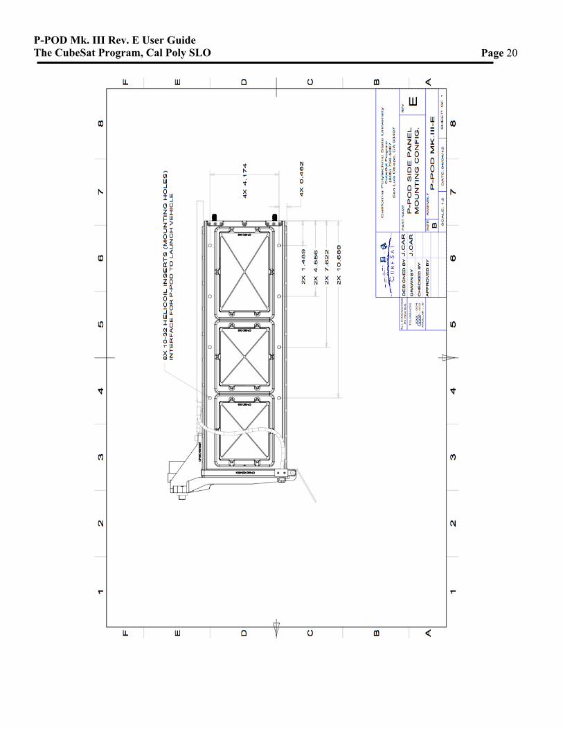
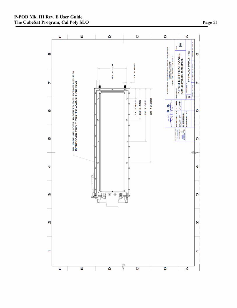
2.2.2 P-POD Mechanical Interface The P-POD is capable of mounting to the launch vehicle or to an adapter on three different surfaces, the bottom panel (-Y) or either side panel (-X or +X), with eight 10-32 bolts. The mounting pattern on the P-POD’s side and bottom panels is shown in Appendix C.
Release Mechanism Electrical
Harness
Switch Guide
Door Stopper
Access Ports Spring Plungers
P-POD Mk. III Rev. E User Guide The CubeSat Program, Cal Poly SLO
Page 11
2.2.3 P-POD Material and Coatings The P-POD is manufactured from Aluminum 7075-T73 and encloses the CubeSats to ensure the safety of the primary payload. The exterior surfaces and internal mating surfaces of the P-POD are alodined as per MIL-DTL-5541F Class 3 to provide corrosion resistance and grounding capability. The interior of the P-POD is hard anodized as per MIL-A-63576 Rev. A with a Teflon coating, creating resiliency to cold welding and providing a smooth, slick surface on which the CubeSats ride during deployment. 2.2.4 Access Ports Access ports provided on the side panels (+/-X faces) of the P-POD allow access to the CubeSat(s) after integration and may be used to charge batteries and run diagnostics.
2.2.5 Deployment Velocity The CubeSat’s exit velocity from the P-POD is approximately 2.0 m/s for 4 kg CubeSat. 2.2.6 Switch Guide A deployment sensor installed on the P-POD Bracket is available to provide telemetry data to the launch vehicle. The switch guide is an attachment to the P-POD door in order to actuate the switch when the door is fully closed. The deployment sensor and switch guide are typically mounted to the +X side of the bracket. For further details on the deployment sensor refer to section 2.4.3. 2.2.7 Door Stopper The P-POD door is designed to open a minimum of 110 degrees and a maximum of 220 degrees, measured from its closed position. The door opening angle can be restricted to the desired position with an optional door stopper.
2.3 Mass Properties and Modal Characteristics 2.3.1 P-POD Mass Properties Masses, moments of inertia, and center of gravity information for the P-POD are provided in Table 2; these values are for reference only and the assumptions are as follows:
• One 3U CubeSat with a uniformly distributed mass of 4 kg • The CubeSat’s center of gravity is located at its geometric center. • The CubeSat is inertially axisymmetric about the P-POD’s Z-axis. • The NEA 9102G is the release mechanism used on the P-POD. • The P-POD door is open 120 degrees from the closed position for the post-deployment
values. • Mass properties do not include harnessing or deployment switches, but do include the P-
POD’s door release mechanism (NEA 9102G).
P-POD Mk. III Rev. E User Guide The CubeSat Program, Cal Poly SLO
Page 12
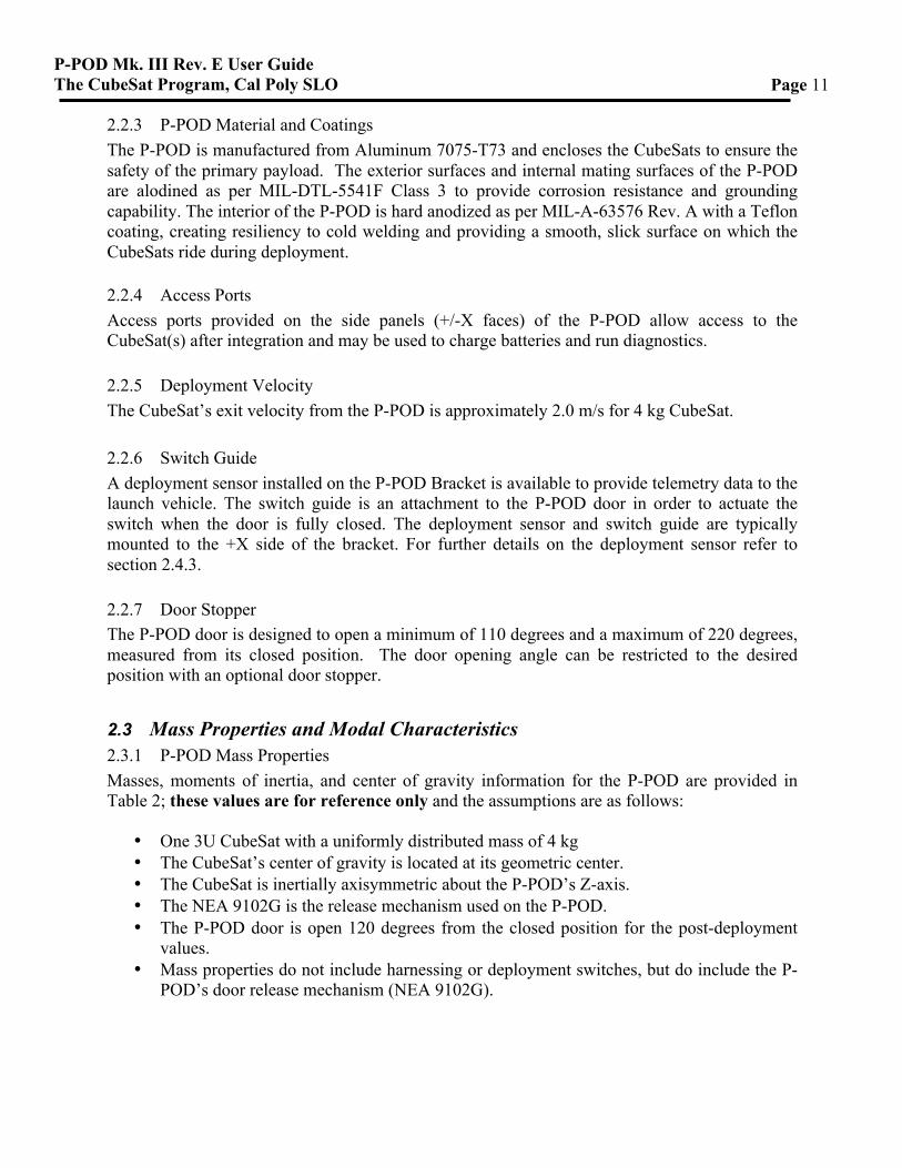
The P-POD’s coordinate system is defined from the center of the outer surface of the back panel (-Z face), with the positive Y-axis coming out the top of the P-POD, and the positive Z-axis pointing out of the front (door) of the P-POD, as shown in Figure 4.
Table 2: P-POD Mk. III Rev. E Mass Properties
Property Pre – Deployment* Post – Deployment** Mass (kg) 7.010 3.010
Moments of Inertia
(kg*mm^2)
Ixx 109929.8 71926 Iyy 107499 66059 Izz 22206.14 19146
Centers of Gravity
(mm)
Xcg 0 0 Ycg 3.9 0.6 Zcg 216.2 240.5
Note: Moments of Inertia are calculated about the P-POD’s Center of Gravity *Values can vary significantly depending on CubeSat payload
**Values can vary depending on harness configuration 2.3.2 P-POD First Natural Frequency The integrated P-POD’s first natural frequency is above 120 Hz. These values were obtained analytically and verified through testing.
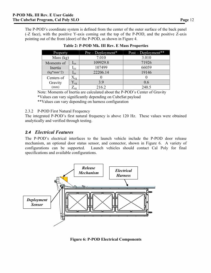
2.4 Electrical Features The P-POD’s electrical interfaces to the launch vehicle include the P-POD door release mechanism, an optional door status sensor, and connector, shown in Figure 6. A variety of configurations can be supported. Launch vehicles should contact Cal Poly for final specifications and available configurations.
Figure 6: P-POD Electrical Components
Release Mechanism Electrical
Harness
Deployment Sensor
P-POD Mk. III Rev. E User Guide The CubeSat Program, Cal Poly SLO
Page 13
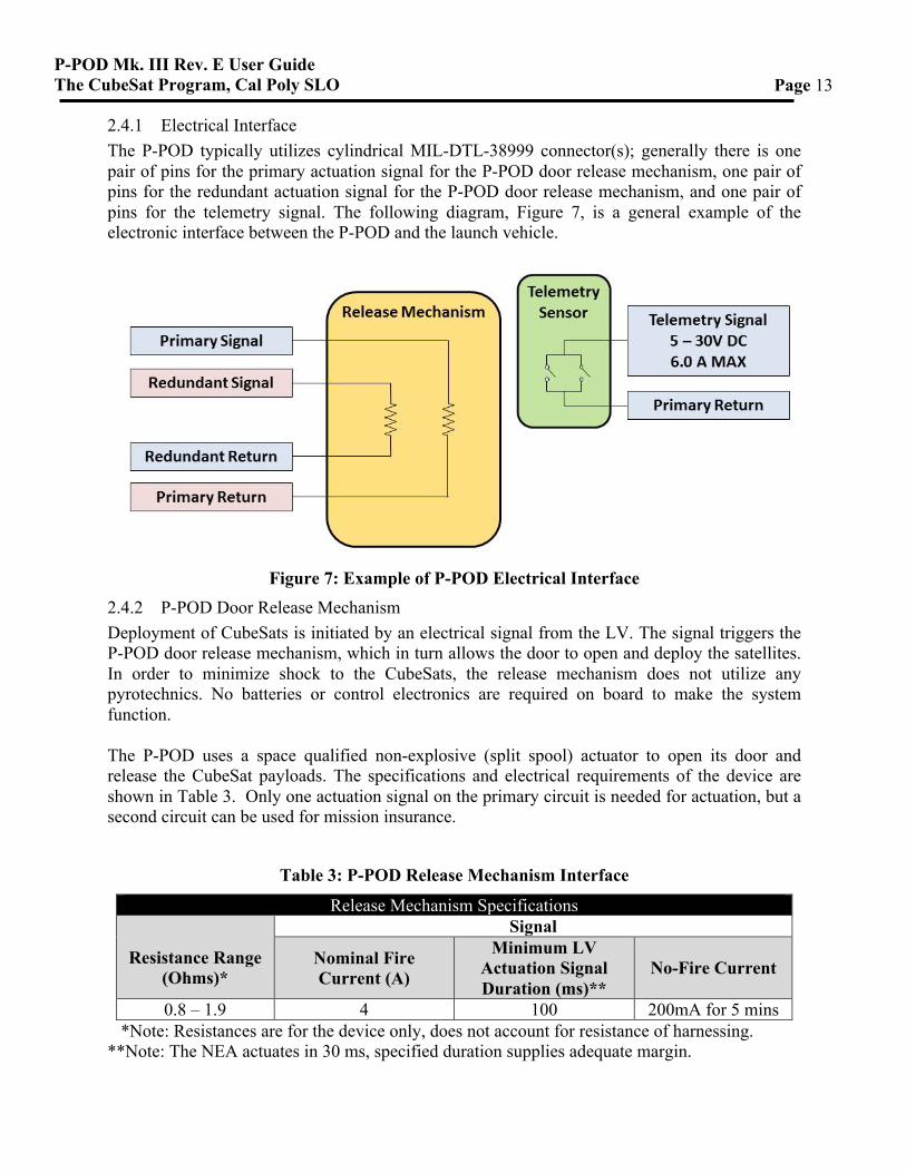
2.4.1 Electrical Interface The P-POD typically utilizes cylindrical MIL-DTL-38999 connector(s); generally there is one pair of pins for the primary actuation signal for the P-POD door release mechanism, one pair of pins for the redundant actuation signal for the P-POD door release mechanism, and one pair of pins for the telemetry signal. The following diagram, Figure 7, is a general example of the electronic interface between the P-POD and the launch vehicle.
Figure 7: Example of P-POD Electrical Interface
2.4.2 P-POD Door Release Mechanism Deployment of CubeSats is initiated by an electrical signal from the LV. The signal triggers the P-POD door release mechanism, which in turn allows the door to open and deploy the satellites. In order to minimize shock to the CubeSats, the release mechanism does not utilize any pyrotechnics. No batteries or control electronics are required on board to make the system function. The P-POD uses a space qualified non-explosive (split spool) actuator to open its door and release the CubeSat payloads. The specifications and electrical requirements of the device are shown in Table 3. Only one actuation signal on the primary circuit is needed for actuation, but a second circuit can be used for mission insurance.
Table 3: P-POD Release Mechanism Interface
Release Mechanism Specifications
Resistance Range
(Ohms)*
Signal
Nominal Fire Current (A)
Minimum LV Actuation Signal Duration (ms)**
No-Fire Current
0.8 – 1.9 4 100 200mA for 5 mins *Note: Resistances are for the device only, does not account for resistance of harnessing. **Note: The NEA actuates in 30 ms, specified duration supplies adequate margin.
P-POD Mk. III Rev. E User Guide The CubeSat Program, Cal Poly SLO
Page 14
2.4.3 P-POD Door Status Sensor One or two deployment sensors installed on the P-POD, near the door, are available to provide telemetry data to the launch vehicle. The switches are wired to create a closed circuit when the door is closed; thus, when the door has opened, the telemetry data sent back to the launch vehicle is an open circuit. This provides knowledge that the P-POD door remains closed until the actuation signal is sent. 2.4.4 Grounding The P-POD is typically grounded through the LV mounting points, but can be grounded anywhere on the alodined surfaces of the P-POD.
3. Contacts
Cal Poly - San Luis Obispo Dr. Jordi Puig-Suari Aerospace Engineering Dept. (805) 756-5165 [email protected] Roland Coelho Program Manager (805) 756-5165 [email protected] Ryan Nugent Aerospace Engineer (805) 756-5165 [email protected]
P-POD Mk. III Rev. E User Guide The CubeSat Program, Cal Poly SLO
Page 15
Appendix A: Static Envelope Drawing
P-POD Mk. III Rev. E User Guide The CubeSat Program, Cal Poly SLO
Page 16
P-POD Mk. III Rev. E User Guide The CubeSat Program, Cal Poly SLO
Page 17
Appendix B: Dynamic Envelope Drawing
P-POD Mk. III Rev. E User Guide The CubeSat Program, Cal Poly SLO
Page 18
11
22
33
44
55
66
77
88
AA
BB
CC
DD
EE
FF
BPA
RT
NA
ME
P-P
OD
MK
.III-E
1
SIZ
EA
SS
EM
BL
Y
E
SC
AL
E:
1:3
04
/04
/12
ALL D
IME
NS
ION
SIN
IN
CH
ES
DE
SIG
NE
D B
Y
CH
EC
KE
D B
Y
AP
PR
OV
ED
BY
DR
AW
N B
Y
SH
EE
T O
F 1
DE
SIG
NE
D B
Y
AP
PR
OV
ED
BY
CH
EC
KE
D B
Y
DR
AW
N B
Y
J.C
AR
J.C
AR
DA
TE
:
RE
V
P-P
OD
DO
OR
O
PE
NIN
G P
AT
H
Ca
lifo
rn
ia P
oly
tech
nic
Sta
te U
niv
ersity
Cu
be
Sat
Pro
gra
m(805) 7
56-5087
Sa
n L
uis
Ob
isp
o,
CA
93
40
7
120
220
14
.54
-14.5�
0.3
5-
0.3� 15
.18
-15.2�
DO
OR
OP
EN
ING
PA
TH
P-POD Mk. III Rev. E User Guide The CubeSat Program, Cal Poly SLO
Page 19
Appendix C: Mounting Pattern Drawings
P-POD Mk. III Rev. E User Guide The CubeSat Program, Cal Poly SLO
Page 20
P-POD Mk. III Rev. E User Guide The CubeSat Program, Cal Poly SLO
Page 21

![Feasibility Investigation of a Cubesat Modular and Rotatable Solar … · 2020. 8. 13. · Figure 2: CubeSat [1] Figure 3: P-Pod [1] Legacy dictates a minimum of six subsystems are](https://img.pdfslide.us/doc/110x75/611b598eca9d6656894144b3/feasibility-investigation-of-a-cubesat-modular-and-rotatable-solar-2020-8-13.jpg)