Embed Size (px)
Citation preview
®
PILOT OPERATED PRESSUREVACUUM RELIEF VALVE
MODEL 1660
600
❏ Premium Seat Tightness to Set Pressure❏ Snap or Modulating Valve Action
❏ Provides Ability to Meet “Clean Air Act Requirements”
Patent Protected
®
INTRODUCTION
Pressure and/or vacuumrelief valves are used on liquidstorage tanks and other processvessels or systems to preventstructural damage due to excessinternal pressure or vacuum.
Storage tanks are pressurizedwhen liquid is pumped in andcompresses the existing vapor orwhen increasing temperaturecauses increased evaporation orexpansion of existing vapor.Conversely, vacuum may be cre-ated when pumping out ordecreasing temperature. To pre-vent damage, vapor must beallowed to escape or enter thetank at a specified pressure orvacuum. The volume rate ofventing depends upon the tanksize, volatility of the contents,the pumping rate and the tem-perature. See API Standard 2000for the procedures to determineventing requirements.
The pilot operated reliefvalve has two principal advan-tages over other types of reliefvalves:
1) It is bubble tight to set pressure.
2) It is fully open at less than10% above set pressure.
These characteristics permitan operating pressure nearer tothe maximum allowable workingpressure of the tank. Highoperating pressures reduce evap-oration and total venting volume,thereby reducing product lossand cost of processing emissions.
A tank may also have provi-sions for emergency pressurerelief due to fire exposure and/oran inert gas blanket in the vaporspace.
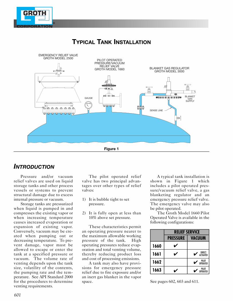
A typical tank installation isshown in Figure 1 whichincludes a pilot operated pres-sure/vacuum relief valve, a gasblanketing regulator and anemergency pressure relief valve.The emergency valve may alsobe pilot operated.
The Groth Model 1660 PilotOperated Valve is available in thefollowing configurations:
See pages 602, 603 and 611.
601
EMERGENCY RELIEF VALVEGROTH MODEL 2500
BLANKET GAS REGULATORGROTH MODEL 3000
SENSE LINE
GAUGE
PILOT OPERATEDPRESSURE/VACUUM
RELIEF VALVEGROTH MODEL 1660
BLANKETGAS
SUPPLY
TYPICAL TANK INSTALLATION
Figure 1
RELIEF SERVICEPRESSURE VACUUM
1660
1661
1662
1663
✔
✔ ✔
✔
✔ ✔
DIRECTACTUATED
PILOT OPERATED
PILOT OPERATED
®
602
GROTH MODEL 1660 FEATURES & APPLICATIONS
FEATURES
• Sizes 2” through 12”• Full Pipe Bore Seat Nozzle• Standard Pressure Settings from 2.0" W.C.
to 15 PSIG• Temperature Range from 2323° F
to 1300° F• Designed for Easy Maintenance• Minimal Spare Parts Requirements
• Inherent Backflow Prevention• ISO 9001 Certified Manufacturing Process• Easily Adjustable Blowdown• Snap Action or Modulating Pilot• Premium Seat Tightness to Set Pressure. • Standard Body Materials are Aluminum,
Carbon Steel, or 316 S.S.
APPLICATIONS
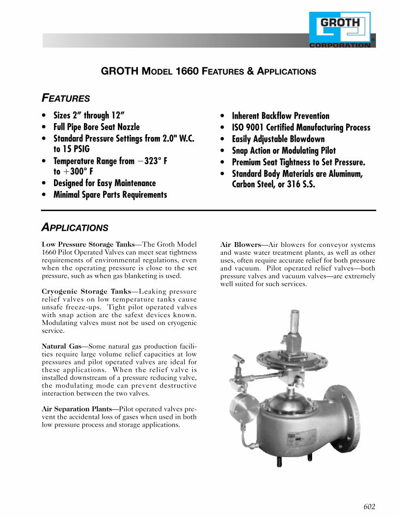
Low Pressure Storage Tanks—The Groth Model1660 Pilot Operated Valves can meet seat tightnessrequirements of environmental regulations, evenwhen the operating pressure is close to the setpressure, such as when gas blanketing is used.
Cryogenic Storage Tanks—Leaking pressurerelief valves on low temperature tanks causeunsafe freeze-ups. Tight pilot operated valveswith snap action are the safest devices known.Modulating valves must not be used on cryogenicservice.
Natural Gas—Some natural gas production facili-ties require large volume relief capacities at lowpressures and pilot operated valves are ideal forthese applications. When the relief valve isinstalled downstream of a pressure reducing valve,the modulating mode can prevent destructiveinteraction between the two valves.
Air Separation Plants—Pilot operated valves pre-vent the accidental loss of gases when used in bothlow pressure process and storage applications.
Air Blowers—Air blowers for conveyor systemsand waste water treatment plants, as well as otheruses, often require accurate relief for both pressureand vacuum. Pilot operated relief valves—bothpressure valves and vacuum valves—are extremelywell suited for such services.
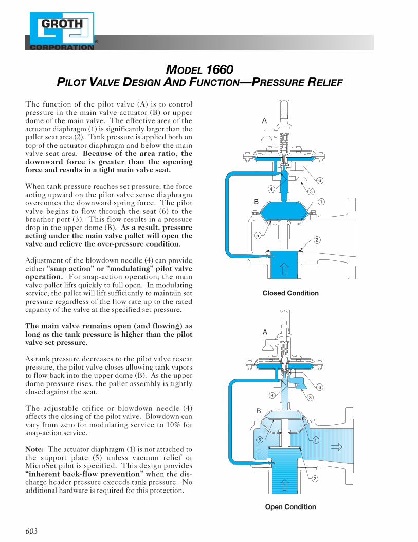
The function of the pilot valve (A) is to controlpressure in the main valve actuator (B) or upperdome of the main valve. The effective area of theactuator diaphragm (1) is significantly larger than thepallet seat area (2). Tank pressure is applied both ontop of the actuator diaphragm and below the mainvalve seat area. Because of the area ratio, thedownward force is greater than the openingforce and results in a tight main valve seat.
When tank pressure reaches set pressure, the forceacting upward on the pilot valve sense diaphragmovercomes the downward spring force. The pilotvalve begins to flow through the seat (6) to thebreather port (3). This flow results in a pressuredrop in the upper dome (B). As a result, pressureacting under the main valve pallet will open thevalve and relieve the over-pressure condition.
Adjustment of the blowdown needle (4) can provideeither “snap action” or “modulating” pilot valveoperation. For snap-action operation, the mainvalve pallet lifts quickly to full open. In modulatingservice, the pallet will lift sufficiently to maintain setpressure regardless of the flow rate up to the ratedcapacity of the valve at the specified set pressure.
The main valve remains open (and flowing) aslong as the tank pressure is higher than the pilotvalve set pressure.
As tank pressure decreases to the pilot valve reseatpressure, the pilot valve closes allowing tank vaporsto flow back into the upper dome (B). As the upperdome pressure rises, the pallet assembly is tightlyclosed against the seat.
The adjustable orifice or blowdown needle (4)affects the closing of the pilot valve. Blowdown canvary from zero for modulating service to 10% forsnap-action service.
Note: The actuator diaphragm (1) is not attached tothe support plate (5) unless vacuum relief orMicroSet pilot is specified. This design provides“inherent back-flow prevention” when the dis-charge header pressure exceeds tank pressure. Noadditional hardware is required for this protection.
Closed Condition
Open Condition
®
603
A
B
4 3
6
1
52
MODEL 1660PILOT VALVE DESIGN AND FUNCTION—PRESSURE RELIEF
A
B
6
3
5 1
2
4
Closed Condition
®
604
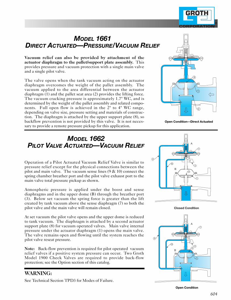
Vacuum relief can also be provided by attachment of theactuator diaphragm to the pallet/support plate assembly. Thisprovides pressure and vacuum protection with a single main valveand a single pilot valve.
The valve opens when the tank vacuum acting on the actuatordiaphragm overcomes the weight of the pallet assembly. Thevacuum applied to the area differential between the actuatordiaphragm (1) and the pallet seat area (2) provides the lifting force.The vacuum cracking pressure is approximately 1.7" WC, and isdetermined by the weight of the pallet assembly and related compo-nents. Full open flow is achieved in the 2" to 4" WC range,depending on valve size, pressure setting and materials of construc-tion. The diaphragm is attached by the upper support plate (8), sobackflow prevention is not provided by this valve. It is not neces-sary to provide a remote pressure pickup for this application.
Operation of a Pilot Actuated Vacuum Relief Valve is similar topressure relief except for the physical connections between thepilot and main valve. The vacuum sense lines (9 & 10) connect thespring chamber breather port and the pilot valve exhaust port to themain valve total pressure pickup as shown.
Atmospheric pressure is applied under the boost and sensediaphragms and in the upper dome (B) through the breather port(3). Below set vacuum the spring force is greater than the liftcreated by tank vacuum above the sense diaphragm (7) so both thepilot valve and the main valve will remain closed.
At set vacuum the pilot valve opens and the upper dome is reducedto tank vacuum. The diaphragm is attached by a second actuatorsupport plate (8) for vacuum operated valves. Main valve internalpressure under the actuator diaphragm (1) opens the main valve.The valve remains open and flowing until the system reaches thepilot valve reseat pressure.
Note: Back-flow prevention is required for pilot operated vacuumrelief valves if a positive system pressure can occur. Two GrothModel 1900 Check Valves are required to provide back-flowprotection; see the Option section of this catalog.
WARNING:See Technical Section TPD3 for Modes of Failure.
A
B
9
1
83
7
10
9
7
3
8
10
A
B
1
MODEL 1662PILOT VALVE ACTUATED—VACUUM RELIEF
8
1
2
MODEL 1661DIRECT ACTUATED—PRESSURE/VACUUM RELIEF
Open Condition—Direct Actuated
Open Condition
®
33
41 42 38
37
40
32
39
29
11
10
9
1
2
3
4
5
6 7
8
1214
3015281819
27
17
20
21
22
2316
24
25
26
31
34 35 36
605
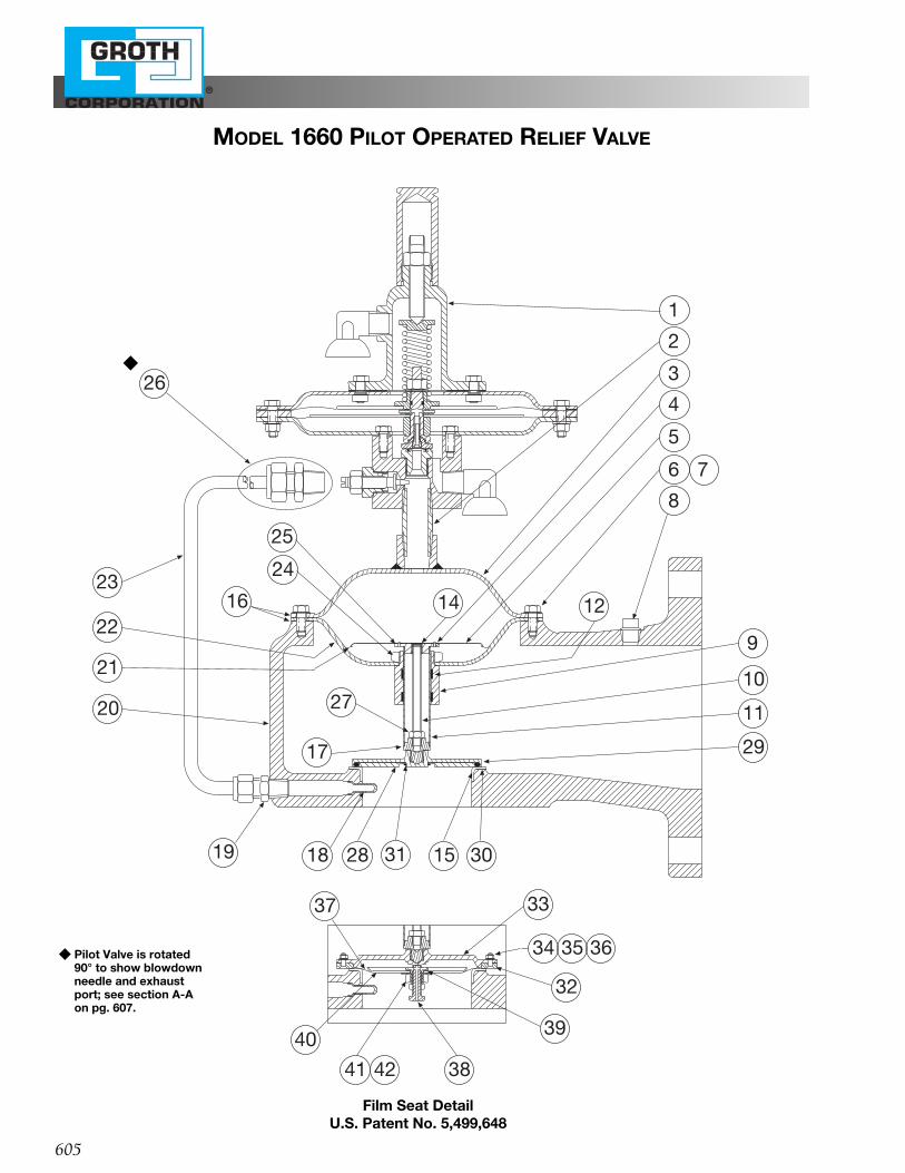
Film Seat DetailU.S. Patent No. 5,499,648
MODEL 1660 PILOT OPERATED RELIEF VALVE
◆ Pilot Valve is rotated 90° to show blowdown needle and exhaust port; see section A-A on pg. 607.
◆
®
606
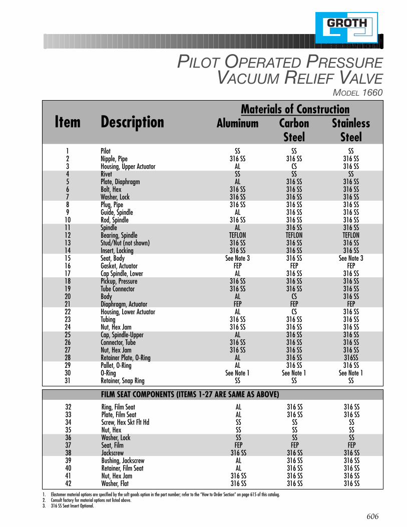
PILOT OPERATED PRESSUREVACUUM RELIEF VALVE
MODEL 1660
FILM SEAT COMPONENTS (ITEMS 1-27 ARE SAME AS ABOVE)32 Ring, Film Seat AL 316 SS 316 SS33 Plate, Film Seat AL 316 SS 316 SS34 Screw, Hex Skt Flt Hd SS SS SS35 Nut, Hex SS SS SS36 Washer, Lock SS SS SS37 Seat, Film FEP FEP FEP38 Jackscrew 316 SS 316 SS 316 SS39 Bushing, Jackscrew AL 316 SS 316 SS40 Retainer, Film Seat AL 316 SS 316 SS41 Nut, Hex Jam 316 SS 316 SS 316 SS42 Washer, Flat 316 SS 316 SS 316 SS
1. Elastomer material options are specified by the soft goods option in the part number; refer to the “How to Order Section” on page 615 of this catalog.2. Consult factory for material options not listed above.3. 316 SS Seat Insert Optional.
Materials of ConstructionItem Description Aluminum Carbon Stainless
Steel Steel1 Pilot SS SS SS2 Nipple, Pipe 316 SS 316 SS 316 SS3 Housing, Upper Actuator AL CS 316 SS4 Rivet SS SS SS5 Plate, Diaphragm AL 316 SS 316 SS6 Bolt, Hex 316 SS 316 SS 316 SS7 Washer, Lock 316 SS 316 SS 316 SS8 Plug, Pipe 316 SS 316 SS 316 SS9 Guide, Spindle AL 316 SS 316 SS
10 Rod, Spindle 316 SS 316 SS 316 SS11 Spindle AL 316 SS 316 SS12 Bearing, Spindle TEFLON TEFLON TEFLON13 Stud/Nut (not shown) 316 SS 316 SS 316 SS14 Insert, Locking 316 SS 316 SS 316 SS15 Seat, Body See Note 3 316 SS See Note 316 Gasket, Actuator FEP FEP FEP17 Cap Spindle, Lower AL 316 SS 316 SS18 Pickup, Pressure 316 SS 316 SS 316 SS19 Tube Connector 316 SS 316 SS 316 SS20 Body AL CS 316 SS21 Diaphragm, Actuator FEP FEP FEP22 Housing, Lower Actuator AL CS 316 SS23 Tubing 316 SS 316 SS 316 SS24 Nut, Hex Jam 316 SS 316 SS 316 SS25 Cap, Spindle-Upper AL 316 SS 316 SS26 Connector, Tube 316 SS 316 SS 316 SS27 Nut, Hex Jam 316 SS 316 SS 316 SS28 Retainer Plate, O-Ring AL 316 SS 316SS29 Pallet, O-Ring AL 316 SS 316 SS30 O-Ring See Note 1 See Note 1 See Note 131 Retainer, Snap Ring SS SS SS
®
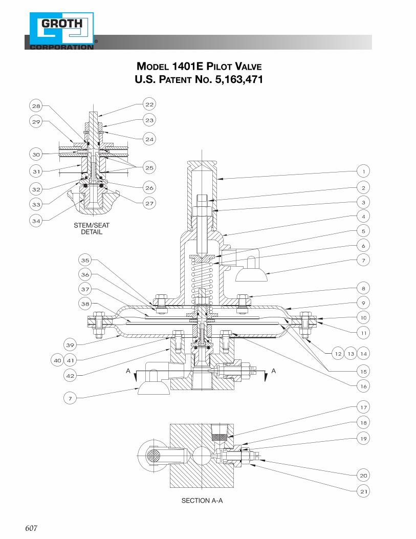
A A
STEM/SEATDETAIL
SECTION A-A
607
MODEL 1401E PILOT VALVE
U.S. PATENT NO. 5,163,471
®
608
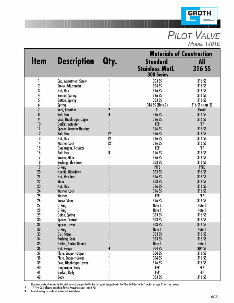
PILOT VALVEMODEL 1401E
1. Elastomer material options for the pilot valve(s) are specified by the soft goods designation in the “How to Order Section” section on page 615 of this catalog.2. 17-7 PH SS or Chrome Vanadium for Set Pressure greater than 8 PSI.3. Consult factory for material options not listed above.
Materials of ConstructionItem Description Qty. Standard All
Stainless Matl. 316 SS300 Series
1 Cap, Adjustment Screw 1 303 SS 316 SS2 Screw, Adjustment 1 304 SS 316 SS3 Nut, Hex 1 316 SS 316 SS4 Bonnet, Spring 1 316 SS 316 SS5 Button, Spring 1 303 SS 316 SS6 Spring 1 316 SS (Note 2) 316 SS (Note 2)7 Vent, Breather 2 AL Plastic8 Bolt, Hex 4 316 SS 316 SS9 Case, Diaphragm-Upper 1 316 SS 316 SS
10 Gasket, Actuator 1 FEP FEP11 Spacer, Actuator Housing 1 316 SS 316 SS12 Bolt, Hex 12 316 SS 316 SS13 Nut, Hex 12 316 SS 316 SS14 Washer, Lock 12 316 SS 316 SS15 Diaphragm, Actuator 1 FEP FEP16 Bolt, Hex 8 316 SS 316 SS17 Screen, Filter 1 316 SS 316 SS18 Bushing, Blowdown 1 303 SS 316 SS19 O-Ring 1 PTFE PTFE20 Needle, Blowdown 1 303 SS 316 SS21 Nut, Hex Jam 1 316 SS 316 SS22 Stem 1 303 SS 316 SS23 Nut, Hex 1 316 SS 316 SS24 Washer, Lock 1 316 SS 316 SS25 Washer 1 FEP FEP26 Screw, Stem 1 316 SS 316 SS27 O-Ring 1 Note 1 Note 128 O-Ring 1 Note 1 Note 129 Guide, Spring 1 303 SS 316 SS30 Spacer, Central 1 303 SS 316 SS31 Spacer, Lower 1 303 SS 316 SS32 O-Ring 1 Note 1 Note 133 Disc, Stem 1 303 SS 316 SS34 Bushing, Seat 1 303 SS 316 SS35 Gasket, Spring Bonnet 1 Note 1 Note 136 Nut, Swage 4 304 SS 304 SS37 Plate, Support-Upper 1 304 SS 316 SS38 Plate, Support-Lower 1 304 SS 316 SS39 Case, Diaphragm-Lower 1 316 SS 316 SS40 Diaphragm, Body 1 FEP FEP41 Gasket, Body 1 FEP FEP42 Body 1 303 SS 316 SS
®
609
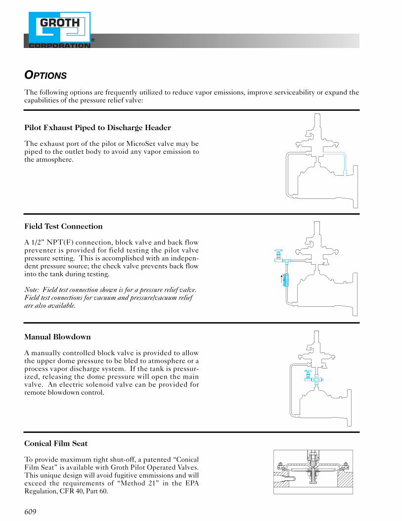
Pilot Exhaust Piped to Discharge Header
The exhaust port of the pilot or MicroSet valve may bepiped to the outlet body to avoid any vapor emission tothe atmosphere.
Field Test Connection
A 1/2” NPT(F) connection, block valve and back flowpreventer is provided for field testing the pilot valvepressure setting. This is accomplished with an indepen-dent pressure source; the check valve prevents back flowinto the tank during testing.
Note: Field test connection shown is for a pressure relief valve.Field test connections for vacuum and pressure/vacuum reliefare also available.
Manual Blowdown
A manually controlled block valve is provided to allowthe upper dome pressure to be bled to atmosphere or aprocess vapor discharge system. If the tank is pressur-ized, releasing the dome pressure will open the mainvalve. An electric solenoid valve can be provided forremote blowdown control.
Conical Film Seat
To provide maximum tight shut-off, a patented “ConicalFilm Seat” is available with Groth Pilot Operated Valves.This unique design will avoid fugitive emmissions and willexceed the requirements of “Method 21” in the EPARegulation, CFR 40, Part 60.
OPTIONS
The following options are frequently utilized to reduce vapor emissions, improve serviceability or expand thecapabilities of the pressure relief valve:
®
610
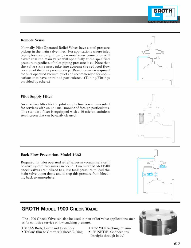
Remote Sense
Normally Pilot Operated Relief Valves have a total pressurepickup in the main valve inlet. For applications where inletpiping losses are significant, a remote sense connection willassure that the main valve will open fully at the specifiedpressure regardless of inlet piping pressure loss. Note thatthe valve sizing must take into account the reduced flowbecause of the inlet pressure drop. Remote sense is requiredfor pilot operated vacuum relief and recommended for appli-cations that have entrained particulates. (Tubing/Fittingsprovided by others.)
Pilot Supply Filter
An auxiliary filter for the pilot supply line is recommendedfor services with an unusual amount of foreign particulates.The standard filter is equipped with a 10 micron stainlesssteel screen that can be easily cleaned.
Back-Flow Prevention, Model 1662
Required for pilot operated relief valves in vacuum service ifpositive system pressures can occur. Two Groth Model 1900check valves are utilized to allow tank pressure to load themain valve upper dome and to trap this pressure from bleed-ing back to atmosphere.
GROTH MODEL 1900 CHECK VALVE
The 1900 Check Valve can also be used in non-relief valve applications suchas for corrosive service or low cracking pressure.
• 316 SS Body, Cover and Fasteners • 0.25" WC Cracking Pressure• Teflon® film & Viton® or Kalrez® O-Ring • 1/4" NPT(F) Connections
(straight through body)
®
611
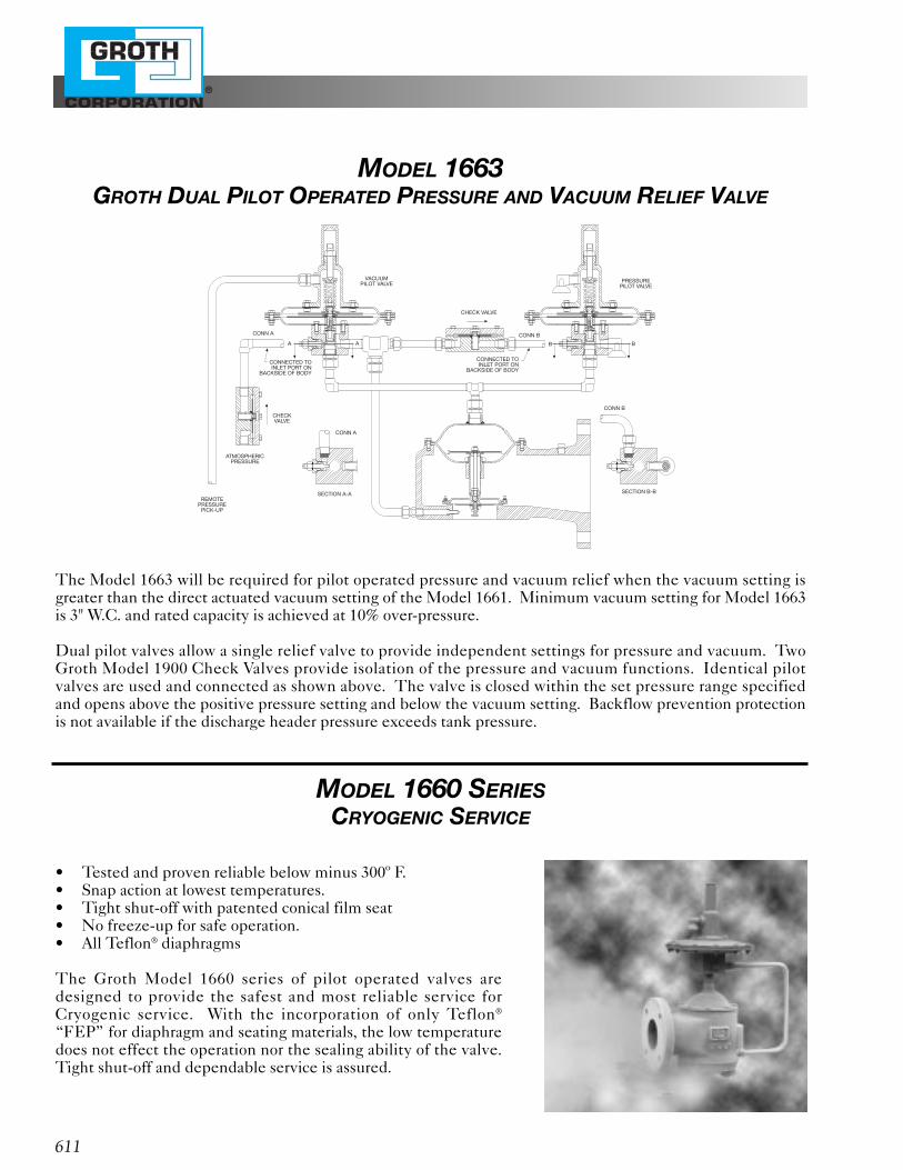
The Model 1663 will be required for pilot operated pressure and vacuum relief when the vacuum setting isgreater than the direct actuated vacuum setting of the Model 1661. Minimum vacuum setting for Model 1663is 3" W.C. and rated capacity is achieved at 10% over-pressure.
Dual pilot valves allow a single relief valve to provide independent settings for pressure and vacuum. TwoGroth Model 1900 Check Valves provide isolation of the pressure and vacuum functions. Identical pilotvalves are used and connected as shown above. The valve is closed within the set pressure range specifiedand opens above the positive pressure setting and below the vacuum setting. Backflow prevention protectionis not available if the discharge header pressure exceeds tank pressure.
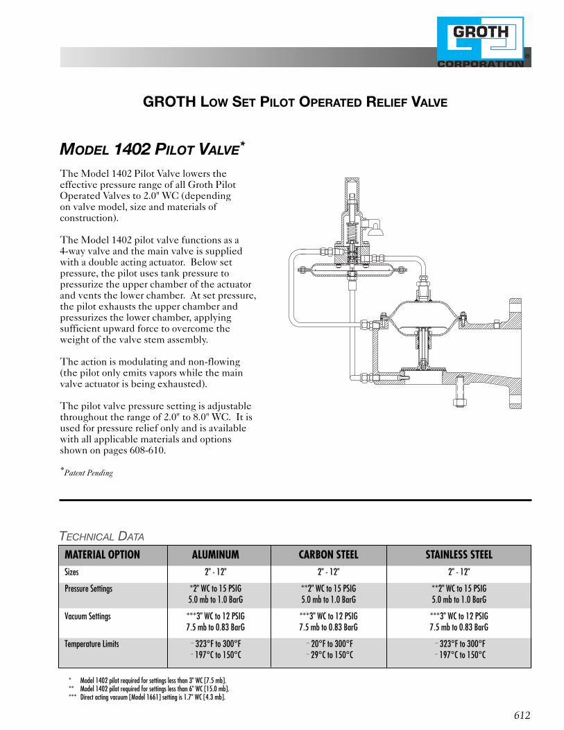
MODEL 1660 SERIESCRYOGENIC SERVICE
• Tested and proven reliable below minus 300º F.• Snap action at lowest temperatures.• Tight shut-off with patented conical film seat• No freeze-up for safe operation.• All Teflon® diaphragms
The Groth Model 1660 series of pilot operated valves aredesigned to provide the safest and most reliable service forCryogenic service. With the incorporation of only Teflon®
“FEP” for diaphragm and seating materials, the low temperaturedoes not effect the operation nor the sealing ability of the valve.Tight shut-off and dependable service is assured.
MODEL 1663GROTH DUAL PILOT OPERATED PRESSURE AND VACUUM RELIEF VALVE
CONN A
CONNECTED TOINLET PORT ON
BACKSIDE OF BODY
CONNECTED TOINLET PORT ON
BACKSIDE OF BODY
A
VACUUMPILOT VALVE PRESSURE
PILOT VALVE
CONN B
B
CONN A
ATMOSPHERICPRESSURE
REMOTEPRESSURE
PICK-UP
SECTION A-A
CONN B
SECTION B-B
CHECK VALVE
CHECKVALVE
A B
®
612
GROTH LOW SET PILOT OPERATED RELIEF VALVE
MODEL 1402 PILOT VALVE*
The Model 1402 Pilot Valve lowers theeffective pressure range of all Groth PilotOperated Valves to 2.0" WC (depending on valve model, size and materials of construction).
The Model 1402 pilot valve functions as a 4-way valve and the main valve is suppliedwith a double acting actuator. Below setpressure, the pilot uses tank pressure to pressurize the upper chamber of the actuatorand vents the lower chamber. At set pressure,the pilot exhausts the upper chamber andpressurizes the lower chamber, applyingsufficient upward force to overcome theweight of the valve stem assembly.
The action is modulating and non-flowing(the pilot only emits vapors while the mainvalve actuator is being exhausted).
The pilot valve pressure setting is adjustablethroughout the range of 2.0" to 8.0" WC. It isused for pressure relief only and is availablewith all applicable materials and optionsshown on pages 608-610.
*Patent Pending
* Model 1402 pilot required for settings less than 3" WC [7.5 mb].** Model 1402 pilot required for settings less than 6" WC [15.0 mb].*** Direct acting vacuum [Model 1661] setting is 1.7" WC [4.3 mb].
TECHNICAL DATA
MATERIAL OPTION ALUMINUM CARBON STEEL STAINLESS STEELSizes 2" - 12" 2" - 12" 2" - 12"
Pressure Settings *2" WC to 15 PSIG **2" WC to 15 PSIG **2" WC to 15 PSIG5.0 mb to 1.0 BarG 5.0 mb to 1.0 BarG 5.0 mb to 1.0 BarG
Vacuum Settings ***3" WC to 12 PSIG ***3" WC to 12 PSIG ***3" WC to 12 PSIG7.5 mb to 0.83 BarG 7.5 mb to 0.83 BarG 7.5 mb to 0.83 BarG
Temperature Limits 2 323°F to 300°F 2 20°F to 300°F 2 323°F to 300°F2 197°C to 150°C 2 29°C to 150°C 2 197°C to 150°C
®
613
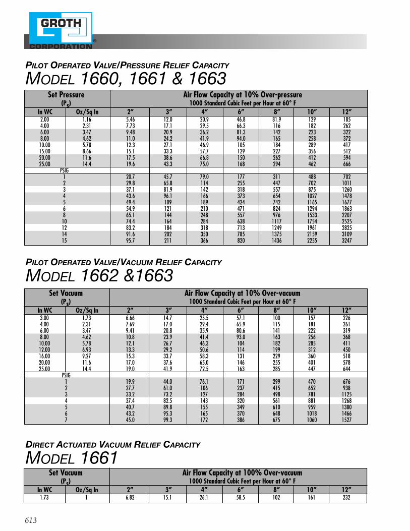
PILOT OPERATED VALVE/VACUUM RELIEF CAPACITY
MODEL 1662 &1663
PILOT OPERATED VALVE/PRESSURE RELIEF CAPACITY
MODEL 1660, 1661 & 1663
DIRECT ACTUATED VACUUM RELIEF CAPACITY
MODEL 1661Set Vacuum Air Flow Capacity at 100% Over-vacuum
(Ps) 1000 Standard Cubic Feet per Hour at 60° FIn WC Oz/Sq In 2” 3” 4” 6” 8” 10” 12”
1.73 1 6.82 15.1 26.1 58.5 102 161 232
Set Pressure Air Flow Capacity at 10% Over-pressure(Ps) 1000 Standard Cubic Feet per Hour at 60° F
In WC Oz/Sq In 2” 3” 4” 6” 8” 10” 12”2.00 1.16 5.46 12.0 20.9 46.8 81.9 129 1854.00 2.31 7.73 17.1 29.5 66.3 116 182 2626.00 3.47 9.48 20.9 36.2 81.3 142 223 3228.00 4.62 11.0 24.2 41.9 94.0 165 258 37210.00 5.78 12.3 27.1 46.9 105 184 289 41715.00 8.66 15.1 33.3 57.7 129 227 356 51220.00 11.6 17.5 38.6 66.8 150 262 412 59425.00 14.4 19.6 43.3 75.0 168 294 462 666
PSIG1 20.7 45.7 79.0 177 311 488 7022 29.8 65.8 114 255 447 702 10113 37.1 81.9 142 318 557 875 12604 43.6 96.1 166 373 654 1027 14785 49.4 109 189 424 742 1165 16776 54.9 121 210 471 824 1294 18638 65.1 144 248 557 976 1533 2207
10 74.4 164 284 638 1117 1754 252512 83.2 184 318 713 1249 1961 282514 91.6 202 350 785 1375 2159 310915 95.7 211 366 820 1436 2255 3247
Set Vacuum Air Flow Capacity at 10% Over-vacuum(Ps) 1000 Standard Cubic Feet per Hour at 60° F
In WC Oz/Sq In 2” 3” 4” 6” 8” 10” 12”3.00 1.73 6.66 14.7 25.5 57.1 100 157 2264.00 2.31 7.69 17.0 29.4 65.9 115 181 2616.00 3.47 9.41 20.8 35.9 80.6 141 222 3198.00 4.62 10.8 23.9 41.4 93.0 163 256 36810.00 5.78 12.1 26.7 46.3 104 182 285 41112.00 6.93 13.3 29.2 50.6 114 199 312 45016.00 9.27 15.3 33.7 58.3 131 229 360 51820.00 11.6 17.0 37.6 65.0 146 255 401 57825.00 14.4 19.0 41.9 72.5 163 285 447 644
PSIG1 19.9 44.0 76.1 171 299 470 6762 27.7 61.0 106 237 415 652 9383 33.2 73.2 127 284 498 781 11254 37.4 82.5 143 320 561 881 12685 40.7 89.8 155 349 610 959 13806 43.2 95.3 165 370 648 1018 14667 45.0 99.3 172 386 675 1060 1527
®
614
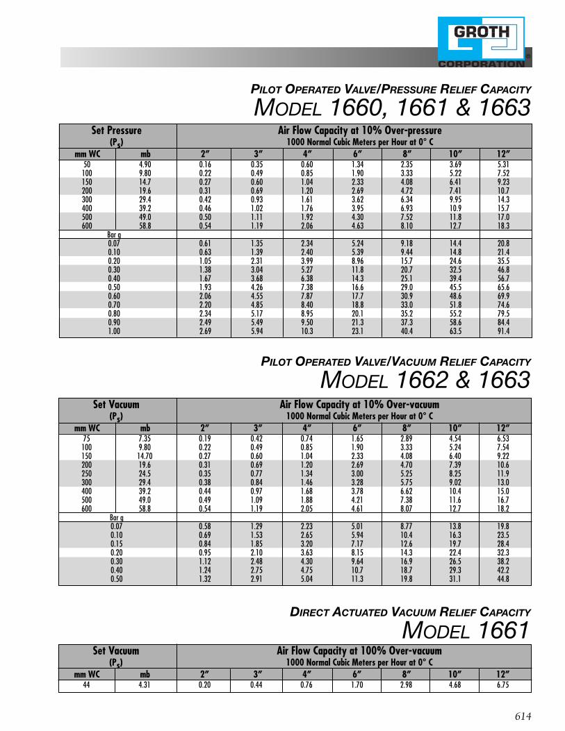
PILOT OPERATED VALVE/VACUUM RELIEF CAPACITY
MODEL 1662 & 1663
PILOT OPERATED VALVE/PRESSURE RELIEF CAPACITY
MODEL 1660, 1661 & 1663
DIRECT ACTUATED VACUUM RELIEF CAPACITY
MODEL 1661Set Vacuum Air Flow Capacity at 100% Over-vacuum
(Ps) 1000 Normal Cubic Meters per Hour at 0° Cmm WC mb 2” 3” 4” 6” 8” 10” 12”
44 4.31 0.20 0.44 0.76 1.70 2.98 4.68 6.75
Set Pressure Air Flow Capacity at 10% Over-pressure(Ps) 1000 Normal Cubic Meters per Hour at 0° C
mm WC mb 2” 3” 4” 6” 8” 10” 12”50 4.90 0.16 0.35 0.60 1.34 2.35 3.69 5.31
100 9.80 0.22 0.49 0.85 1.90 3.33 5.22 7.52150 14.7 0.27 0.60 1.04 2.33 4.08 6.41 9.23200 19.6 0.31 0.69 1.20 2.69 4.72 7.41 10.7300 29.4 0.42 0.93 1.61 3.62 6.34 9.95 14.3400 39.2 0.46 1.02 1.76 3.95 6.93 10.9 15.7500 49.0 0.50 1.11 1.92 4.30 7.52 11.8 17.0600 58.8 0.54 1.19 2.06 4.63 8.10 12.7 18.3
Bar g0.07 0.61 1.35 2.34 5.24 9.18 14.4 20.80.10 0.63 1.39 2.40 5.39 9.44 14.8 21.40.20 1.05 2.31 3.99 8.96 15.7 24.6 35.50.30 1.38 3.04 5.27 11.8 20.7 32.5 46.80.40 1.67 3.68 6.38 14.3 25.1 39.4 56.70.50 1.93 4.26 7.38 16.6 29.0 45.5 65.60.60 2.06 4.55 7.87 17.7 30.9 48.6 69.90.70 2.20 4.85 8.40 18.8 33.0 51.8 74.60.80 2.34 5.17 8.95 20.1 35.2 55.2 79.50.90 2.49 5.49 9.50 21.3 37.3 58.6 84.41.00 2.69 5.94 10.3 23.1 40.4 63.5 91.4
Set Vacuum Air Flow Capacity at 10% Over-vacuum(Ps) 1000 Normal Cubic Meters per Hour at 0° C
mm WC mb 2” 3” 4” 6” 8” 10” 12”75 7.35 0.19 0.42 0.74 1.65 2.89 4.54 6.53
100 9.80 0.22 0.49 0.85 1.90 3.33 5.24 7.54150 14.70 0.27 0.60 1.04 2.33 4.08 6.40 9.22200 19.6 0.31 0.69 1.20 2.69 4.70 7.39 10.6250 24.5 0.35 0.77 1.34 3.00 5.25 8.25 11.9300 29.4 0.38 0.84 1.46 3.28 5.75 9.02 13.0400 39.2 0.44 0.97 1.68 3.78 6.62 10.4 15.0500 49.0 0.49 1.09 1.88 4.21 7.38 11.6 16.7600 58.8 0.54 1.19 2.05 4.61 8.07 12.7 18.2
Bar g0.07 0.58 1.29 2.23 5.01 8.77 13.8 19.80.10 0.69 1.53 2.65 5.94 10.4 16.3 23.50.15 0.84 1.85 3.20 7.17 12.6 19.7 28.40.20 0.95 2.10 3.63 8.15 14.3 22.4 32.30.30 1.12 2.48 4.30 9.64 16.9 26.5 38.20.40 1.24 2.75 4.75 10.7 18.7 29.3 42.20.50 1.32 2.91 5.04 11.3 19.8 31.1 44.8
615
®
GROTH IS COMMITTED TO THE TOTALQUALITY IMPROVEMENT PROCESS
1202 Hahlo • P.O. Box 15293Houston, Texas 77220-5293
713/675-6151 FAX 713/675-6739Groth Products Group
1-800-552-2960 (Except Tex. & La.)
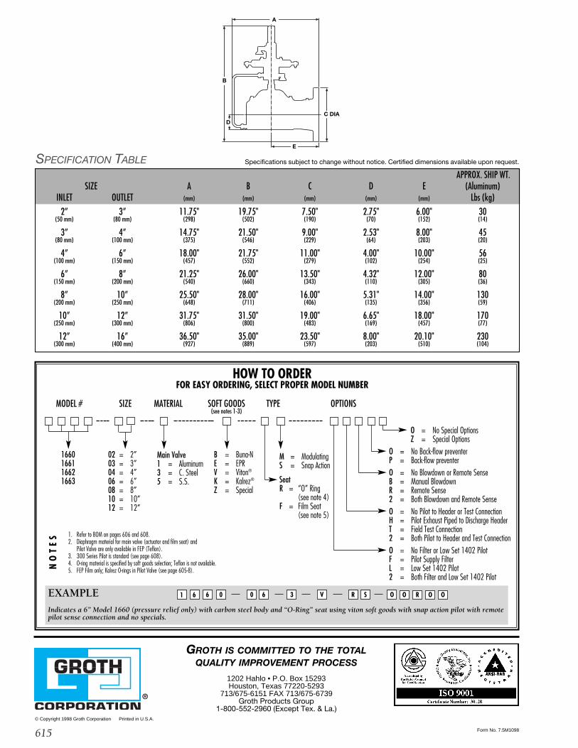
HOW TO ORDERFOR EASY ORDERING, SELECT PROPER MODEL NUMBER
MODEL # SIZE MATERIAL SOFT GOODS TYPE OPTIONS(see notes 1-3)
1660166116621663
02 = 2”03 = 3”04 = 4”06 = 6”08 = 8”10 = 10”12 = 12”
Main Valve1 = Aluminum3 = C. Steel5 = S.S.
B = Buna-NE = EPRV = Viton®
K = Kalrez®
Z = Special
1. Refer to BOM on pages 606 and 608.2. Diaphragm material for main valve (actuator and film seat) and
Pilot Valve are only available in FEP (Teflon).3. 300 Series Pilot is standard (see page 608).4. O-ring material is specified by soft goods selection; Teflon is not available.5. FEP Film only; Kalrez O-rings in Pilot Valve (see page 605-8).N
OT
ES
O = No Special OptionsZ = Special Options
O = No Back-flow preventerP = Back-flow preventerO = No Blowdown or Remote SenseB = Manual BlowdownR = Remote Sense2 = Both Blowdown and Remote SenseO = No Pilot to Header or Test ConnectionH = Pilot Exhaust Piped to Discharge HeaderT = Field Test Connection2 = Both Pilot to Header and Test ConnectionO = No Filter or Low Set 1402 PilotF = Pilot Supply FilterL = Low Set 1402 Pilot2 = Both Filter and Low Set 1402 Pilot
EXAMPLE
Indicates a 6” Model 1660 (pressure relief only) with carbon steel body and “O-Ring” seat using viton soft goods with snap action pilot with remote pilot sense connection and no specials.
0 0 R O6 66 31 S O R O O
M = ModulatingS = Snap Action
SeatR = “O” Ring
(see note 4)F = Film Seat
(see note 5)
V
© Copyright 1998 Groth Corporation Printed in U.S.A.
Form No. 7.5M1098
SPECIFICATION TABLE Specifications subject to change without notice. Certified dimensions available upon request.
D
A
B
E
C DIA
A
B
E
DC DIA
APPROX. SHIP WT.SIZE A B C D E (Aluminum)
INLET OUTLET (mm) (mm) (mm) (mm) (mm) Lbs (kg)
2” 3” 11.75" 19.75" 7.50" 2.75" 6.00" 30(50 mm) (80 mm) (298) (502) (190) (70) (152) (14)
3” 4” 14.75" 21.50" 9.00" 2.53" 8.00" 45(80 mm) (100 mm) (375) (546) (229) (64) (203) (20)
4” 6” 18.00" 21.75" 11.00" 4.00" 10.00" 56(100 mm) (150 mm) (457) (552) (279) (102) (254) (25)
6” 8” 21.25" 26.00" 13.50" 4.32" 12.00" 80(150 mm) (200 mm) (540) (660) (343) (110) (305) (36)
8” 10” 25.50" 28.00" 16.00" 5.31" 14.00" 130(200 mm) (250 mm) (648) (711) (406) (135) (356) (59)
10” 12” 31.75" 31.50" 19.00" 6.65" 18.00" 170(250 mm) (300 mm) (806) (800) (483) (169) (457) (77)
12” 16” 36.50" 35.00" 23.50" 8.00" 20.10" 230(300 mm) (400 mm) (927) (889) (597) (203) (510) (104)
![The Interregnum (1649-1660) The “Interregnum” Period [ 1649-1660 ] †The Commonwealth (1649-1653) †The Protectorate (1654-1660)](https://img.pdfslide.us/doc/110x75/56649e725503460f94b718c7/the-interregnum-1649-1660-the-interregnum-period-1649-1660-the.jpg)


![5 - Control Valves 5 - Control Valves - Brunnbauer …...Increased: 3·10-3D· D p [cm3min] (Class V to PN-IEC 60534-4) Globe control valve BR 12a 5 - Control Valves 5 - Control Valves](https://img.pdfslide.us/doc/110x75/5ee45125ad6a402d666d7fa1/5-control-valves-5-control-valves-brunnbauer-increased-310-3d-d-p-cm3min.jpg)