Embed Size (px)
Citation preview
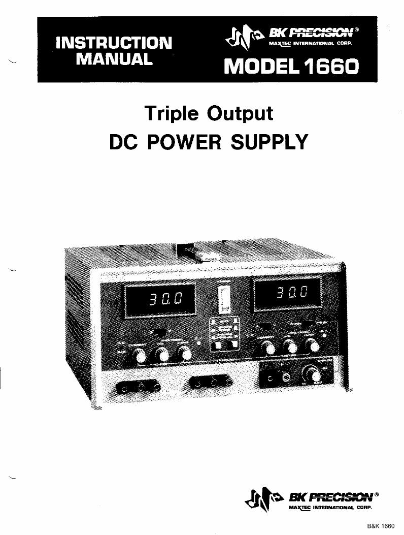
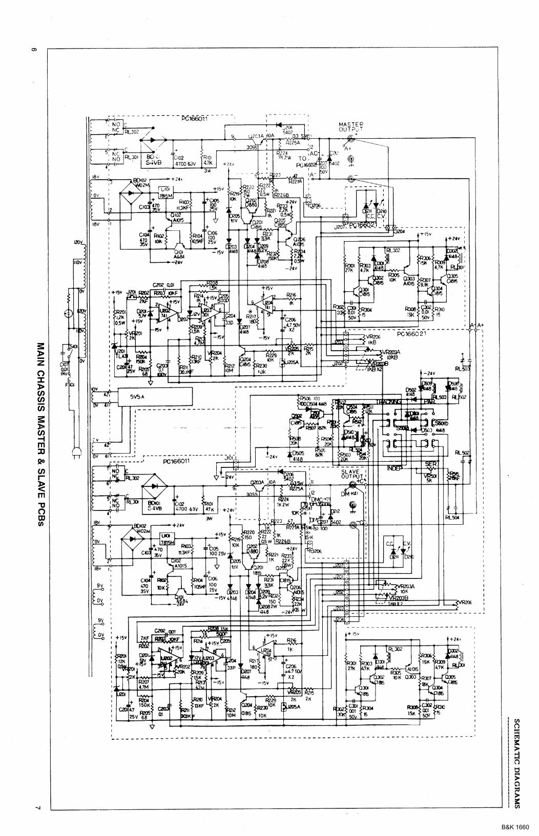
Triple OutputDC POWER SUPPLY
dlt*rur#ffi.i'B&K 1660
TEST INSTRUMENT SAFETY
- Normal use of test equipment exposes you to a celtain amor,rnt of dangel flohelectrical shock because testing ncust sohetioes be perfolrbeal \phere exposeil highvoltage is plesent. An electrica.I shock causiDg l0 milliamps of curlent to passthlougb the healt wilt stop most hu6an heartbeats. Voltage as Iow as 35 volts dc o!ac llrs should be consideled dangelous and hazardous sin-ce it can proaluce a lethalcurlent under celtain conditioDs. Higher voltage poses an even gleate! tltleat be_cause suc-h voltage can laore easily ploduce a Iethal culreDt. your normal workhabits should include all accepted plactices that will prevent contact rrith exposealhigb voltage, and that wiu stee! current a\eay flom you! healt in case of accialentalcontact rpith a high voltage. You will sigtrificantly leduce tbe lisk facto! if youknow and obselve the followirg safety plecautions:
1. There is little dange! of electrical shock IroE the dc output of this powersupply. Hoeever, thele ale sevelal other possible test conditions using thispowe! supply that can cleate a high voltage shock hazard;
a. If the equipment utde! test is the "hot chassis,, tvDe. a selious shockhazard exists unless tbe equipEent is uDplugged (usi turning off theequipment does aot remove the hazard), o! the plecautions ot Jtep g areobserved.
b. If the equipbeDt under test is "powered upi (arxd that equipEent useshigh voltage in ary of its cilcuits), the polve! supply outputs may befloated to the potential at the point of connection, Remeober that highvolta_ge Inay appea! at unexpected points in defective equipbeot. Dollot float tbe po.re! supply output to more tban 100 voit; peak withlespect to chassis or earth ground.
c. If ttre equiproent under test is ,off', (and tbat equipEent uses high vol_tage ilr aIly oI its circuits unde! nornra.I opelatiotr), discbalge higb_voltage capacitors before baking coDnectioDs or tests. SoEe cilcuitsretaiD high voltage long after the equipraeDt is tuDed off,
Z. Use olly a poladzed 3-wi!e ac outlet. This assures that the powe! supplycha6sis, case, and ground telrainal ale conlected to a good eartir Stounil anilreduces dange! florD electlical shoclg
3. DoD't expose high vottage neetllessly. Remove bousiags aDd covels only wheaneceasaly, T[ra off equipEe[t while Eaking test coDnectioDs in higb-voltagecilcuits. Discbarge higb-voltage capacitols after reEo\ring powe!.
4. lf possible, faEiliafize youlseu with the equipE ent beiDg testeal and the lc_cation of its high voltage points. However, letlembe! tbat high voltage Dlayappear at rEerpected poiuts in delective equipmert.
waRl||ltc
{codtinued oa inside rear cover)
B&K 1660
lnstruction Manualfor
Jt1}lr, s(t^Ect--,tMAXSE9 TNTER ATONAL CoPrr.
Model 1660
Triple Output
DC POWER SUPPLY
H( PEECES'-,JMAGg TNTEFNAIIONAL coFP.6470 w Corlland St . ChlcaSo, lL6O635
B&K 1660
TABLE OF CONTENTS
page
T E S T I N S T R U M E N T S A F E T Y . . . , . i r s i d e f r o n t c o i e r
I N T R O D U C T I O N . , " . . . . . . . I
F E A r i j l l E S . . . . . . . 3
s P l j c i i : : a - . ! r : l N : - i . . . . . . , , ' 4
C O N T R O L S A J I I N D I C A T O R S . . . . . . - . . .G e n e r a l C o n t t o l s A n d l n d i c a t o r s . . . . . . . . . . . 54 - 6 . 5 \ ' s u p p l y C o n t r o l s A n d l n d i c a t o r s . . . . . . . . . . 5Ma.ster Suppl-v Controls ,{nd lndicatols . . , . . . . . ' . . . . . . . . 5S l a v e S u p p l - v C o n t r o l s A n d I n d i c a t o r s . . . , . . . . . . . . , . . ?R e a - l P a n e l C o n t r o l s . . . . . . . . ' . . . . . . 8
C P E R A T ] N G I N S T R U C T I O N S . . . . . , , , , , 9S a f e t - v P r e c : . r r t i o n s . . . . . . , 9E q u i p m e n t P r e c a u i i o n s . . . . . . . . . . . . . 9l n d e p e n d e n t U s e O f " M a s t e r " O r " S 1 a v e " S u p P l ] ' . . . . . . . . 9S e r i e s T r a c k i n g O p e l a t i o n . . . . . . . . . 1 3P a - r a l l e i T r a . c k i n g o p e r a i i o n . . . . . . ' . 1 6, 1 - 6 . 5 V P o i r e l S u p p l y O p e l a t i o n . . ' . . . . . . ' ' . ' . 1 9
A P P L I C A T I O N S . . . . . . , . . , . Z OG e n e r a t . . . . . ' . . . . . . . . . 2 0E l e c t r o n i c s S e r v i c i n g . . . . . . . . . . . . . 2 0E l e c t r o n i c s M a n u f a c t u r i n g . . . . . . . . . 2 0E l e c t l o n i c s D e s i g n L a b . . . . . . . . . , Z 0E l e c t l o n i c s E d u c a t i o n . . ' ' ' ' . . . 2 1B a t t e r y C h a r g i n g . . . . . - . . Z IS p l i t S u P P I - \ ' . , . . . . . . . . . . 2 1
M A I N T E N A N C E . . , . . . . . " . . 2 5
F u s e R e p l a c e m e n t . . . . . . 2 5L i n e v o l t a g e C o n v e r s i o n ' , . , . . . - - . . 2 5A d j u s t m e n t s . . . ' . . . . - - 2 6l n s t r u m e n t R e p a i ! S e r v i c e . . . . . ' . ' . 3 0
W A R R A N T Y S E R \ T C E I N S T R U C T I O N S . . . . . . . . . . 3 1
U M I T E D O N E . Y E A R W A R R A N T Y . . . . . . . . . . . . . 3 2
B&K 1660
INTRODUCIION
Tbe B & K-hecisi@ Model 1660 TripleOutput DC Powe! Supply is a higb quality,genela.l purpose dc power soulce. It providestwo supplies with a 0-30 volt dc output andong with a 4-6.5 volt dc output. The 0-30 vsupplies are adjustable with both coarse aJIdfine voltage contlols for precise settabilityand are capable of current output of0-2 arops. The 4-6.5 v supply has a currentoutput of 0-5 a.Eops, allowillg it to hanille ex-tensive digita.l Iogic circuitry. Two la.rgepalel-Eoormted LED oete! displays caD moEi-tor eithe! the output curtent or output voltageo{ each supply.
The two 0-30 volt supplies can be opelatedindependendy or in one of two tlackilgr:oodes. In the selies tlackilg Eode, the Slavesupply tracks the voltage of the Ma.ste!supply, MaxiEuo curlent settidg of the twosupplies can still be set independently \rhen inthe selies tlackitrg operating 6ode, In theseri€s tlacking mode the Maste! aIId Slavesupplies a.!e connected in se es, allowing asingie output of 0-60 V at up to 2 aDcps. In thepatallel tlacking Eode, the two supplies aleconnected together iD parallel, allo\ring a sin-gle 0-30 V output at up to 4 amps.
Both 0-30 volt supplies may be used itrconstant voltage o! constart cutrent appli-caiioDs. The clossove! floB constant voltageto constant cu.!!ent modes is sEooth a.ndautoEatic. LED'S indicate tbe "CV' (coDstantvoltage) or "CC" (corBtant cu!!e!rt) l3ode ofoperation. In constart voltage applications, acurlent limit loay be preset, when load va-ri-ations cause the c{rlent to reach the presetlioit, the unit then regulates output cu!]entlathe! tha! output voltage. Cullent liloits areadjustable frorD 5% to 10070 oI b:axixouEr. IrIconstant current applications, the rDaxirDurDvoltage may be preset. When load valiatioascause cuJrent to dlop below the legulatedvalue, the unit reverts to legulated voltageoDeration at the Dreset value,
allows tbe supply to be used for large ci!-cuits, Built-in ovelload protection auto-matically liEits to cutiebt output to a Eaxi-loull] of 5 aEps. An indicato! lights when thesupply is ovelloaded,
The Model 1660 exhibits excellent regu-Iation ard low pple charactelistics. The ciFcuit design incolpolates a pre-legulato!, whic-hgreatly leduces intelnal powe! dis6ipation atlow output voltages.
Revetse polarity protection plevents acci-dedtal daEage to the poi/ef supply lroE iE-ploper coDnection to a.a extelnal voltage, andcurreat lioitilg plotects the equipEeDt beingpowered, as weII aE the power supply.
The output is isolated flou chassis alrdearth glound, which p€lmits full flexibility ofcomections. Wbed needed, the (+) o! (-) po-Iality llay be stlapped to glound, o! eitherpolarity !!ay be floated to an extelnal vol-tage. Additiona.Uy, the two 0-30 volt suppliescan be used as a "split supply" with two posi-tive voltages and a comDon negative, twoaegative voltages and a cotDllon positive, orone positive, otre negative, and a cor!6on. AIIof these coiligurations ca]l be used with eithe!datching (tlacking) or dif f eling {independent)voltages.
The features aJId versatility oI the unit,especially tbe triple output and trackingfeatues, make it an ideal genefal purposepowe! supply for engineering lab appli-catioas. It can serve as a single o! multi-voltage powe! source, including tbe bias suFply, fo! breadboard and Fotot]?e circuits andequipEent. It can provide single o! sillul-taneously valying voltages for ctcuit eva.lu-ation. It can provide tracking (+) and (-) vol-tages fo! evaluating diffelential aEplifiers. Itmay be used as a battery eliminator, or topower individual circuit boalds o! caril6 whiletemoved llom the systeh, Its output ca'I beevafuated vrhile poweling a bleadboald orDrototv'De cilcrdt to determine the cilcuit's
The 4-6,5 V supply is ideal for poweringdigital logic circuitly, The 0-5 allp capacity
B&K 1660

INTRODUCTION
powel suppty requi!emerts. Its labo!atoryquality specifications will loeet most engi-neering labo"a.tory requi!ements.
The same featules that make the Mod€l1660 a good choice fo! a]} engiaeeling lab also
Dake it a good choice fo! dost other solidstate electronic applications. These apPli_cations include selvice shops; industrial Pro-duction testing of coDrponents' assembli€s, andcollplete equipment; fo! school labolatolies,and home use bv electronic hobbyists.
B&K 1660
FEATURES
TRIPLE OUTPUTOperates as thlee separate power suppl ies.Eacb has f loat ing output and is completelyisolated f lom the other two.
ONE ,{ TO 6.5 V SUPPLYHusky 0-to-5 amp 4-to-6.5 volt suPpty isideal fo! use with Dost di$tal logiccirclritly, Adequate cuilent capacity forextensive circuitly.
TWO O-30 VOLT SUPPLIESMaster and Slave supply are continuouslyvariable ovel 0-to_30 volt range with coarseand fine controls. Each supplv has a Z ampcurrent capacity.
UMQUE TRACKING FEATUREThe two 0-to-30 V suppl ies can be operatedso that the Slave supply tracks the Mastersupply. Outputs can be strapped fot twoposit ive vol tages with a comDon negatrve)two negat ive volLages di th a common posi_tive, or one positive and one negative witha neutra. l common.
SINGII G6O V SUPPLYSeries tracking feature allows use of Masterand Stave supplies as one 0-to-60 V. Z alnpsupply.
SNNGIJ O_30 V 4 AMP SUPPLYPalal lel t racking feature al lows l ise ofMaste! and Slave supply as a 0-to'30 Vsupply with a :1 amp current capacity(through MasteF output terminals)
CONSTANT VOLTAGE OR CONSTANTCURRENT
The Master and slav- .Lppl ias pro! d-regulated dc voltage output or regulated dc
.urent output- Crossover is sEooth and
LED DISPLAYTwo large, easy-to-read LED 3-1l2 digi tdisplays monitol outPut voltage or outputcu.relrt of aU three supplies. Use of twometers allows simultaneous current andvoltage metering when use M3ste! alldSlave suppl ies in tracking oPerat ioD. Goodvisibl i l ty in br ight o! loq l ight. Meterauows resolut ion of 0.1 vol t or 0.1 amp.
LABORATORY QUAIITYExcel lent !eeulat ion. 1o$ t iPPle.
LED INDICATORSIdent i fy mode of ope!at ion.
PRE-REGULATORLimits internal dissipat ion {o! hiehe.rel iabi l i ty and ef f ic iency.
ISOLATED OUTPUTEither pola.rity may be floated or grounded.
OVERI-OAD PROTECTIONFul lv adjustable cul lent l imit ing ( from 5%to 100% of mdimurn output curent l lorVaste! and Slave suppl ies protects circurtunder test and the Poq er suPPlY.
REVERSE POLAR.ITY PROIECTIONPrevents damage to porter supplv l rcrmexternal vol tage of revelse polar i tv
HOOK.UP CABLES,suppl ied with three sets of red ard blackhook-up leads.
B&K 1660
SPBC�IFICATIONS
ITASTBR AND $../lVE SUPPLIT-S Load Reeulatiod (C@start Vottage):
outFt vortrge Rage, = l0 ov (0 to 5 A load)'
0 v {+0/-30 mv) to 30 v + (3 b 1qo)' Lire RegutatioD 108 - l3z v (coEtaDt
OutFrt Curl€ot Lieit Rdge: VoltaSe):0 A (+0/-30 EA) to 2 A +(3Vo to 7Vo). <10 DcV.
Load Regulatio! (Cdstart Voltage): Ripple A.!d Nobe:< 0 . 0 1 % + 3 b V . = Z r b V R M S ,
LiDe R*ulatioD 108 - 132 V (Consta"rVoltage):
-- OvelYoltage hotection Thteshold:
< 0 .01% - 3 bv .
Rittrtle (CoDsteDt Voltag€): Peel Meter Accuract':< I EV RMS. Same as Maste! Suppiy Mete!.
Recoeery TlEe (Constart Voltage):< loo ss' cENERAL
Tehlr Coclficieot (C@rtart Voltage):= 3OO ppb/oc. Poeer RequireEents:
110/1zo/220/z4o vAC !1070. s0/60 I lz-Load R€gulation (CcE3ta[t CrErent]:
< 0.2Vo +3 mA- po;'er CoDsurnptioD (FuIy Loaded):
Lile Reguration 108 - l3z v (c@start ApproxiEately 320 \4t'
CErent):< O.Z7o +3 E'A. hotection:
Revelse poladty protection and cur!entRilple Cr|f!€ot (at 108 V Io! CoDstant liEiting.Crttfeot]:
< 3 IlA RMS. DiDeDsiors (E :< Y r D):165 x 315 x 381 b ra (12 .4 x 15 x 6 .5 " ) ,
Tbackiry (S€ries):t1.Zqo +10 nV, E'eigbt:
P&el lileter Accrracy (volts): 10 kg (22 lbs)'i0.5% + 2 digits.
pdel Metet Acc|racr (cEreDt): TffiS,"Tff;?up leads, I !ed, I black.J0,5 % + 2 digits. Two ea.rth ground bus stlaps.
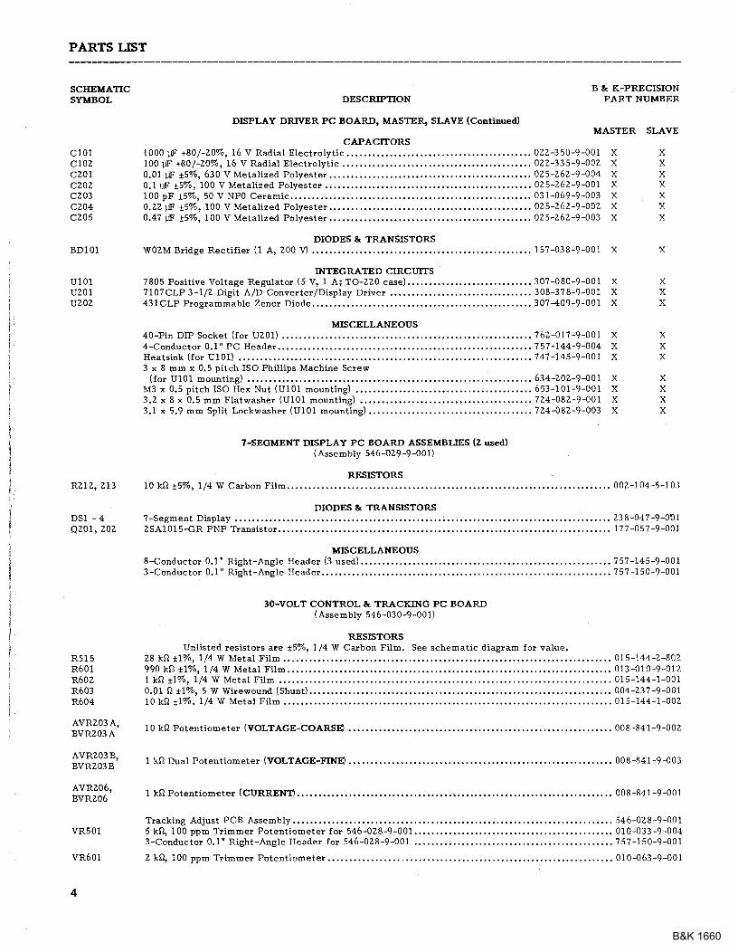
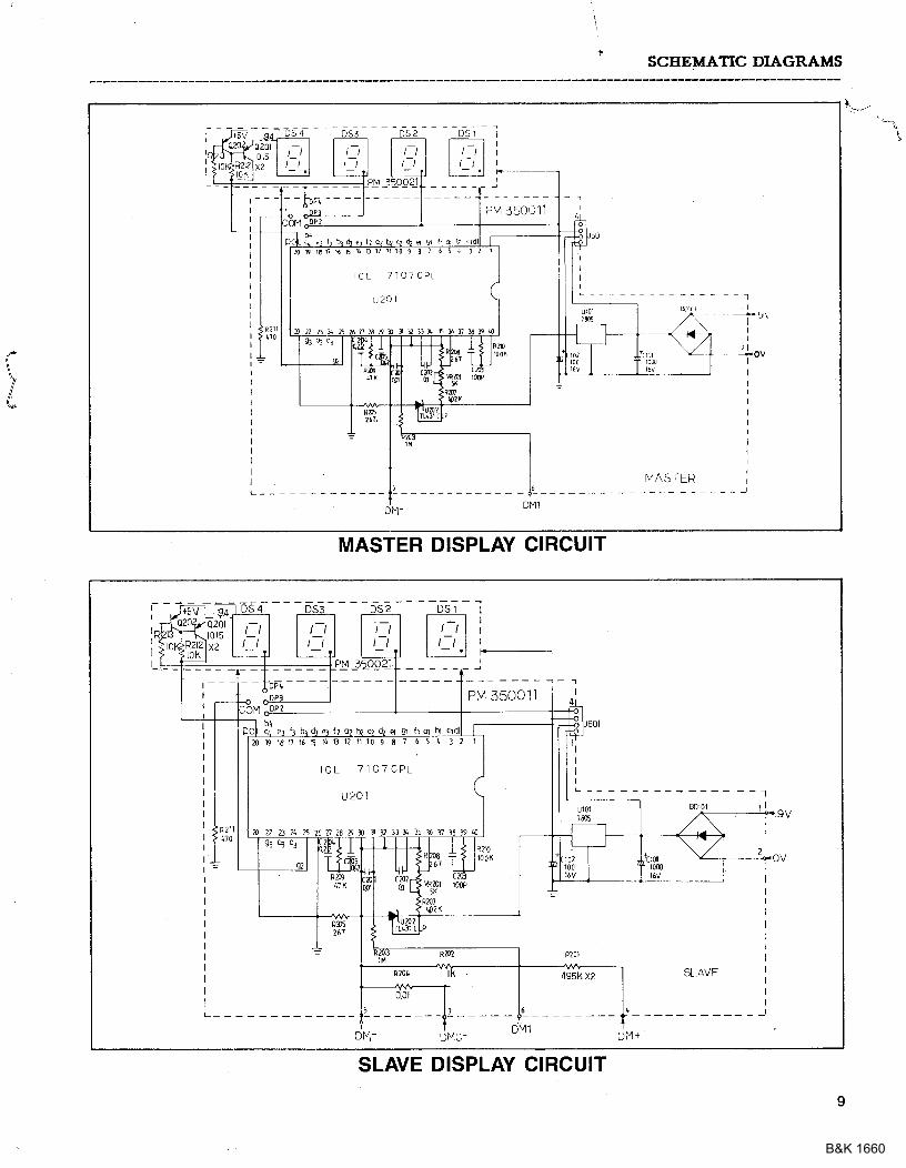
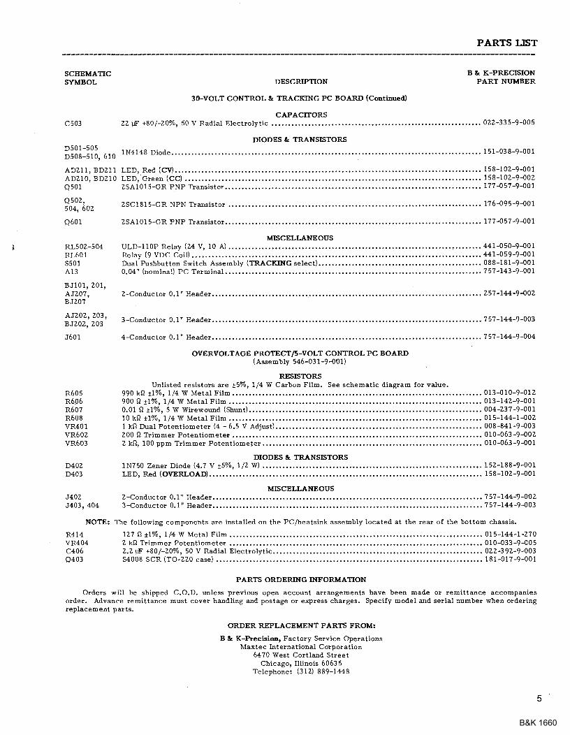
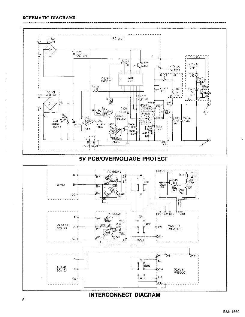
Two 5A, 250V fuses (spares),,F&5 V SUppLy Schematic DiagraB & palts List,
OutFrt Volt.€e RaDg€: Ootionel Accessori€3:4 Y t57o to 6.5 V r5Vo. Fp-tO l6-amp test leads (t red, 1 black).
B&K 1660

CONTROLS AND INDICATORS
GENERAL CONTROLS AND INDICATORS
1. POWER Ssitch- Tutns Power on andoff , When powel is on, sxi tch is inter-nally iuuEi ated to serve as a Pilot light.
Z. TRACKING Mode Seitch€s. Two push-button switches that select INDEPendentoode, series tlacking mode, or Parauelt!acking mode as follows:
a. When both switches are disengag€d(out), the unit is in the INDEPen-dent mode arld the MASTER ardSLAVE power suPPlies are com-pletely ind€Pendent llom oneanotDel,
b, When the lef t switch is engaged ( in)
and the right switch is disengaged(out), the r]nit is in the TRACKINGSERIES mode. In this mode, maxi-mum voltage of both suPPlies is setusing the MASTER VOLTAGE con-tlols (voltage at outPut telminalsof the SLAVE supply ttacks the voi-tage at the output teloinals of theMASTER supplvl. AIso. in thisroode of operatiod the Positiveterminal (red) of the sLAvE supplyis connect€d to the negat ive termi-nal (blackl of the MASTER supPly.This a]lo\rs the two suPplies to beused as one 0- to-60 vol t suPPIY.
c. When both switches ate engaged(in), the uiit is in the TRACKINGPARALLEL rnode, ln this dode theMASTER and SLAVE suPPlies a.!ewiled together in palallel and boththe maxilouE cuirent and voltageare set using the MASTER con-trols. The MASTER alrd SLAVEoutputs can be used as two iDdi-vidual (but tracking) power suPPliesor just the MASTER output can beused as a 0-to-30 volt supply with a4 A capability,
3. (F30 V/+6.5 V Ssitcb Controls MAS-TER/,1-6.5 V LED DisPkY. wlen thisswitch is in tbe G30 V position' the LED
display looniiors the MASTER (0-30 V)supply, when this switch is i! thetr-5 V posit ion. the LED disPlay moni-tors the 4-6.5 \' supply.
.1. A/V Switcb- Selects current cr voltag€meterirg mode for the MASTER 0-30 vsupply or the ,F6.5 V supply (dep€ndiBgoD setting of (F30 V/,1-6.5 V switch).When in the A (amPs) position, cu.rlent isread from the MASTER/,|6.5 V LED Dis-play. When in the V (vo1ts) position' vol-
tage is read from the MASTER/ 'F6.5 VLED Dispray.
5. MASTER/4-6.5 v LED Dispray. Digitaldis?tay indicates voltag€ or cuffent atthe O-30 v MASTER supply or the'1-6.5 v
supply (depending on the setting of theMASTER A,/V aid 0.30 V/4'6.5 'V
4'6.5 V SUPPLY CONTROLS ANDINDICATORS
6. '-' Tedrinal (Blact). Negative Polatityoutput terminal for 4-6.5 V suPPIy'
?. "+" T€rniral (Red)- Positive Polarityoutput terminal for 4-6.5 v supPly.
8. Voltag€ Level C€'rtrol. Adjusts outputvoltage to! 4'6.5 V supply, Fully coun-terclockwise !otation adjusts otttput voi_tage to 4 V. Clockwise rotat ion in-cleases voltage to a maximuEr of 6 '5 v(ful l c lockwise rotat ion).
9. 5 A OVERLOAD IDdicatot. Lights whenload on 4_6.5 Volt suPply becoloes too1arge.
MASTER SUPPLY CONTROLS ANDINDICATORS
10. C.C. (CoDstant Crr'ledt) Irdicator. RedLED lights when MASTER SUPPIY is inthe ConstaDt Cu$e$t mode' The Powe!
B&K 1660
CONTROLS AlfD INDICATORS
I
E66
- l0 l
Il3
ti; fr '.li+:,. I
E E Il3
l4
I820212526 17 15
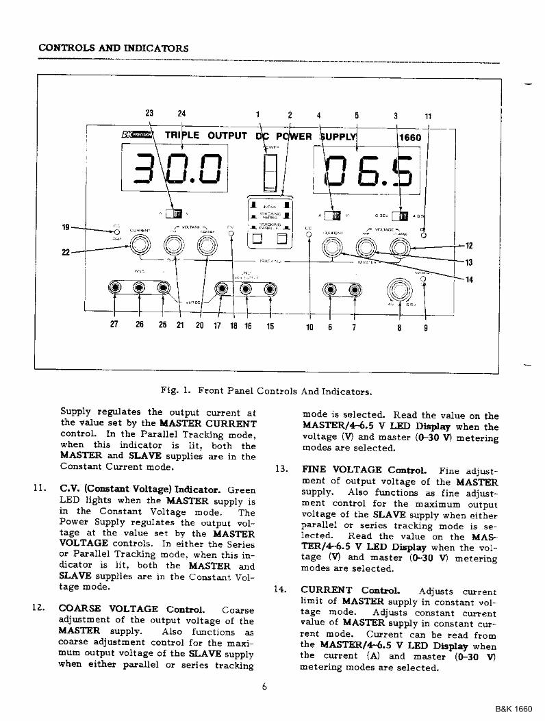
Fig. l. Front Panet Contlols And Indicatols.
1 1 .
13 .
Supply regulates the output culleDt atthe va.Iue set by the IIASTER CURRENTcontrol. In the Parallel Tracking Eod€jwhen this indicato! is lit, both trleMASTER aJId SLAVE supplies are in rneConstant Current Eode.
C.V. (C@staDt Voltage) Iadjcator. GreenLED lights when the MASTER suppty isir the Constant Voltage mode, ThePower Supply regulates the output vot,tage at the value set by the MASTERVOLTAGE controls. ln erther the SeFiesor Paral lel Tracking Eode. when rhrs in-dicator is lit, both the MASTER alrdSLAVE supplies are in the CoDsta.nt Vol-tage mode,
COARSE VOLTAGE Corttol. Codseadju.stment of the output vottage of theMASTER supply. Atso functjons acoarse adjustEenr cout lol fo! the maxiEouh output voltage of the SLAVE supplywhen eithe! paraUel o! seli€s tracunp
Eode is selected. Read the value on theMASTER/4.6.5 V I,ED Distr'lay when thevoltage iv) and master l(F30 V) Eeterinsmodes ale selected.
FINE VOLTAGE Cmbol. Fine adrusr-ment of output volrage of the MASIIERsupply. A160 firnctions as fine adjust-Dent control fo! the Ea-{iEum outDutvoltage of rhe SLAVE suppty when ei t ierpalallel ol se es trackiDg mode is se-lected. Read the value on the MAS-aE.R/4.5 V IlD Display when the vol-tage rV) af ld Daste} ,(F30 l / meter insIIrodes are selected.
CURRENT C@trol. Adjusts currenrIimil of MASTER suppty in constant vol-tage rDode. Adjusts constant curlentvalue of MASTER supply in constant cuJ-lent mode. Cutrent can be aead ftolcthe MASTER/4.6.5 V LED Display whenthe current {A) and rDaster ((F30 umetedng modes are selected,
rz.
B&K 1660
CONTROI.S AND INDICATORS
oo
€
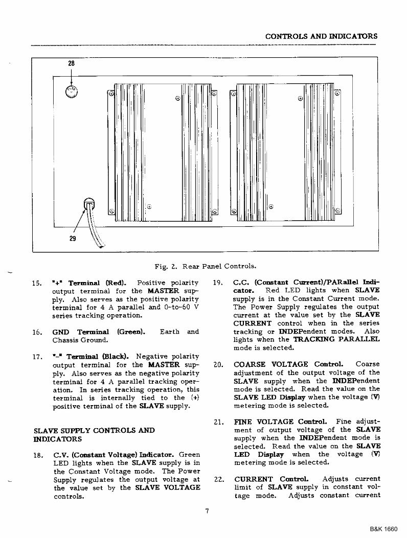
Fig. Z. Reat Panel Controls'
15, '+' TerEiral (Re(l). Positive polarity 19.output telminal fo! the MASTER suFply. Also serves as the Posit ive Polar i tyterminal for 4 A palallel aJId 0-to-60 Vseries tlacking oPelatiotl.
16. GND T€fmiDal (Green). Earth aJIdCbassis Ground.
17. '-' T€rminal Elack). Negative polarityoutput telminal for the MASTER sup- 20.ply. AIso selves as the negative Polaritytelroinai for 4 A palal lel t lackiDg opeFation. In series tlacking opelation. thistelminal is intelnally tied to the {+)positive telminal oI the SLAVE suplly'
21.SLAVE SUPPLY CONTROIS ANDINDICATORS
18. C.V. (CoD3taDt Voltage) Indicato!. GreenLED lights when the SLAVE supply is inthe Constant Voltage mode. The PowerSupply regulates tle output voltage at 22.the value set by the SLAVE VOLTAGE
C,C. (C@stant Curr€.rt)/PARalle-r I t-cator. Red LED lights when SLAVEsupply is in the Constant Culreirt mode'The Powe! Supply legulates the outputcurrent at the value set bv the SLAVECURRENT contlol when in the seliestrackiag o! INDEPendent modes. AIsolights when the TRACKING PARALLELmode is selected.
COARSE VOLTAGE Cdlrol, Coarseadjustment of the outPut voltage of theSLAVE supply when the INDEPerdentmode is selected. Read the value on theSLAVE LED DisCay when the voltage (9metel ing rDode is selected.
FINE VOLTAGE Control. Fine adjust-xoent of output voltage of the SLAVEsuppiy when the INDEPendent Eode isselected. Read the value on the SLAVELED Display when the voltage 19Eeter ing mode is selected.
CURRENT C@trol Adjusts curentlimit of SLAVE supply in constant vol-tage trode. Adjusts co$stant curlent
B&K 1660
CONTROLS AND INDICATORS
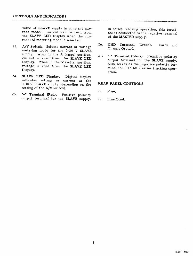
value of SLAVE supply in constant cu;!,rent mode. Current can be .ead fromthe SLAVE LED Display wher the cur,lent (A) meter ing mode is selecled.
23. A/V SFitc-b. Selects current or voltagemetering mode for tbe 0-30 V SLAVEsupply, When in the A (aqlps) positiotl,culnt is lead from the SLAVE LEDDisplay. When in the v (volts) position,voltage is read lrom the SLAVE I-EDDisplay.
24. SLAVE LED Display. Digitat disptayiddicates voltage or current at the0-30 V sl-AvE supply (depending on thesett iDg of the A/V switch),
25. '+' Tetbiaal (Red). positive potadtyoutput telminal for the SLAVE suppty,
In series tracking operation, this termi*nal is connected to the negat ive terminalof the MASTER supply.
26. cND TerEciDa.l (c!een). Ealth andCha.ssis Ground.
27. "-" Terminal (Blact). Negative pot:rityoutput terminal fo! the SLAVE supply.AIso selves as the negative polarity te!-miDal Io" 0-to-60 V series tracking opeF
REAR PANEL CONTROLS
28. Fuse.
29. Line Cold
B&K 1660
OPERATING INSTRI'CTIONS
SA.FETY PRECAUIIONS
cAuttoL
Avoid contacting the heat sinksat the lear oI the power supply,Wben the unit is ploviding largea&ounts of cu$ent at any or allof its outputs, the lteat sinks canbecoEe very hot. CoDtactingthe heat sinks when they ale hotcould lesult itr skin burDs o!damage to the equipEeEt in con-tact with thetn.
Use only a polarized 3-wi!e acoutlet. This assures that thepower supply chassis, case, andground terEinal are connectedto a good earth ground and re-duces dange! flom electlicalshock.
There Eay be great danger ofelectrical shock if the powe!supply output is conDected to anextelDal high voltage. SoDeequipdent beiDg poweled maycontain high voltage and plesent
Althottgh the power supply is protectedagainst levelse polarity daEage, the cilcuitbeing powered Eay not include such PIo-tection. Always calefully obselve polarity;incoffect polarity loay daEage the equiprdentunder test.
Do not exceed tbe voltage rating ot the ci!-cuit being powered- Many transistots andintegrated cilcuits will not *ithstand voltage
There is tro $eed to wo!!y about voltagespikes o! ovelshoot damagiDg the equipEentunder test. The voltag€ between tbe outputterEinal,s of the power supply neve! exceedsthe preset value as the POWER switch isturtted on or off.
INDEPENDENT USE OF 'I,ASTER' OR.SLAVE' SUPPLY
The "MASTER" and "SLAVE" supplies eachplovide a 0-to-30 volt output at up to 2.0aDps. This plocedure covers the use of tbeMASTER ard SLAVE supplies only when theyare used independently from one another.When used in the INDEPendent opelatingmode, the opelatiEg contlols of the t\ro powe!supplies are colt|pletely independent and eithe!supply can be used ildividually o! both can beused sidultaneou.sly. Basic operation iscovered be!e. Several vadations are coveredin the APPLICATIONS section oI this Eanual.
Eool-r{)
l. Diseugage both TRACKING modeswitches (both switches out) so that thepowe! supply is in the INDEPeDdentoperating rbode.
2. TUrn off the power supply and theequipEent to be poweled during hook-up.
3. Condect the positive polarity of thedevice being powered to the red (+) teFllinal of the powe! supply.
Obse!vecautioD, Ii the power supplyoutput is floated (lefelenced toa voltage ratbe! than earthgrotllld) turn off the powersupply a.Ild the equipEelt uDde!test when making connections.Never float the power supply toa potential gleat€! than100 volts peak with lespect toeattb ground"
EQIJIPXENT PRICAUTIO S
Avoid rising the powe^r supply in ambiertteEpelatures above +40" C. Always allowsufficient air space alound the heat sink at thelear of the powe! supply for effective ladia-tior to prevent internal heat build-ul.
a sbock hazald"
B&K 1660
OPERATING INSTRUCTIONS
I !.! ,l r E . [ _'1 f'l a'1 1 | t- t-l t s . u
I l-',r.f, f D,D
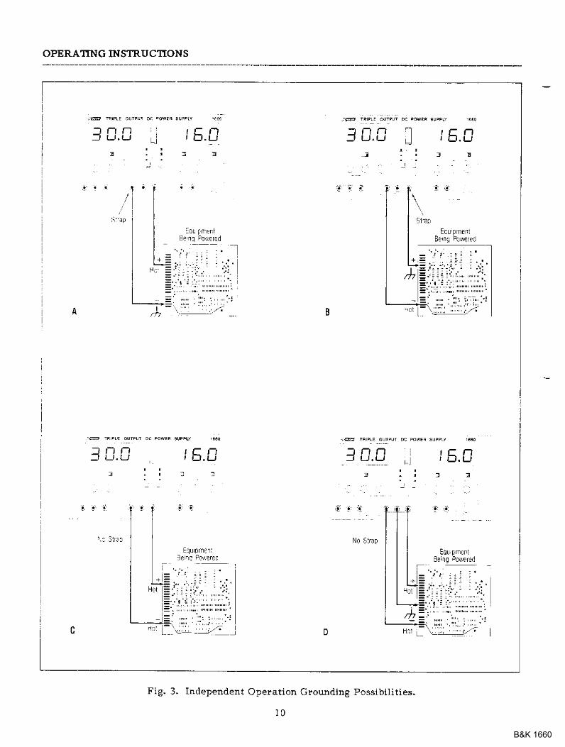
Fig. 3. Independent Operat ion Grounding Possibi l i t ies.
1 0
B&K 1660
OPERATING INSTRUCTIONS
i[. Connect the negative pola]ity of thedevice being povreled to the black Hterminal of the powe! supply.
5. Fig. 3 illustlates the glounding possibil-ities when used in the INDEPendent
a. If t]re negative polality of theequipoent ol ctcuit being poweredis also the chassis o! common, itmay be glounded to eatth bystlapping the black (-) telminal tothe g!€en (GND) teroinal as sho\rnin Fig. 3A.
b. Similarly, the positive polarity canbe groulded by strapping the red (+)terminal to the gleen (GND) termiRal as shown in Fig. 3B.
c. If aI} ea-lth $ourd refer€nce is notrequired, the codfiguratio. of Fig,3C may be used. The scheEe inFig. 3C should also be used where itis not krown whether the chassis iscommon wi ih ei ther the Posit ive o!negative polality,
d. If the chassis or common of theequipEent being powered is sePa-r^fF fr^m hoih thF Dosit ive andnegative polarity power inputs' usethe connect ion shown in Fig. 3D.
6, Observe ploper pola.rity. II the cilcuitbeing poweled is not equipped with re-verse polarity plotection, darnage to thecircuit can lesult froE reverse polarity,Use color coded hook-up leads, such asthe sets supplied \tith the powe! supply'for convenience in identifying polarity,red for (+) and black for (-).
?. Make sure that the hook-uP leads offersufficieDt cuilent capability and low !e-sistance between the power supply andthe circuits being poweled. Th€ hook-upIeads supplied with the powei supply arera.ted fo! 3 arDps.
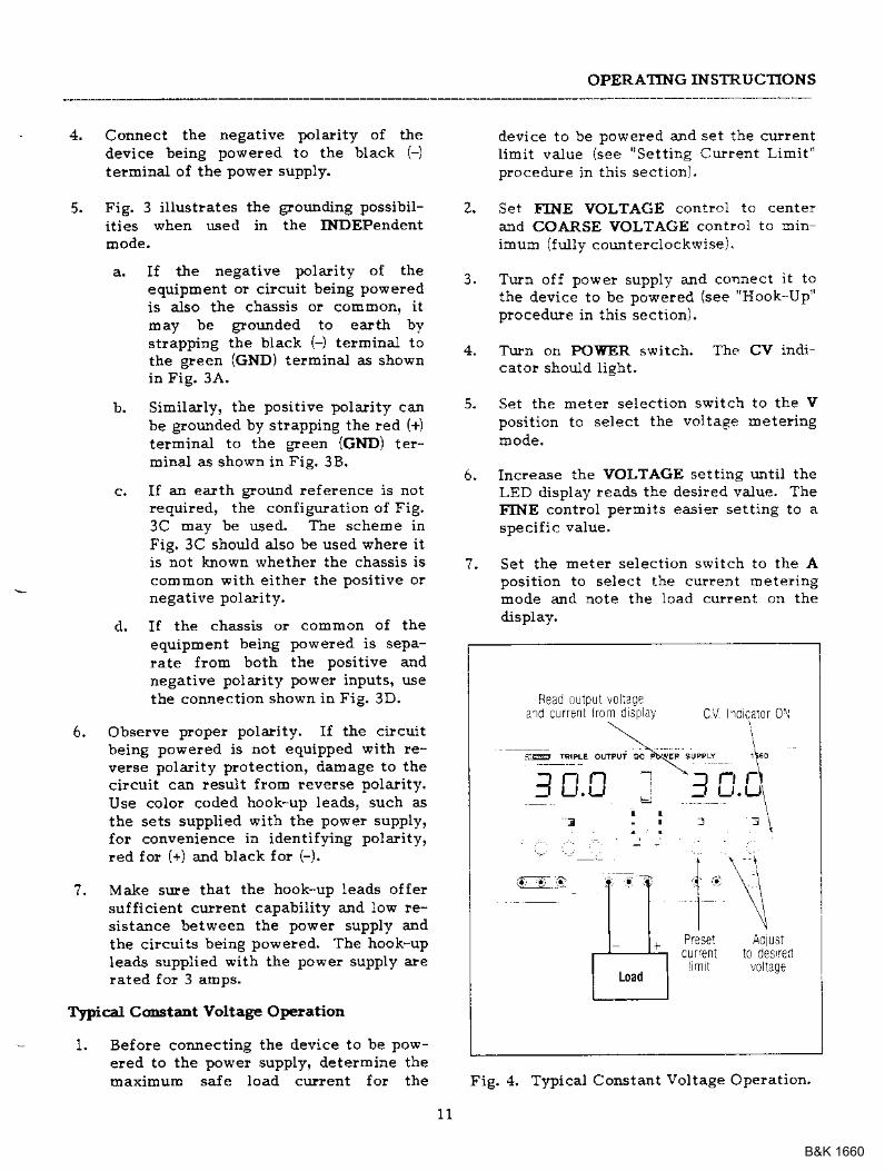
Typical C('rstant Voltage OFlation
Befoie connecting the device to be pow-eled to the power supply, determine themaximum safe load curent for the
device to be powered and set the cut lentl imit value {see "Sett ing CuFent Limit"n ' ^ . o ; ! ! i 4 i n i h i < c . . r i ^ r l
Set FINE VOLTAGE control to c€nterand COARSE VOLTACE control ro:r inimu& (f ul ly cotrnterclockwise).
Turn off power suppll' and corurect it tothe device to be powered (see "Hook-Up"
procedure in this sect ion).
Turn on POWER switch. The CV indicato! should l ight.
Set the meter select ion switch to the Vposit ion to select the v^' tae- mete?ingmode.
Increase the VOLTAGE setting until theLED display rea.ds the desired valu€. TheFINE control permits easier setting to aspecif ic value,
Set the meter select ion switch to the Aposit ion to select the cu$ent oetFr ingmode and note the load curient on thedisplay.
3 .
6 .
7 .
1 .
Fead oulPr t !c iaQea'ro currsnl l rom dspa! CV r0cai0r 01i
\ i\ l
oc 4{EF sumY ,F0
I [.C - '_] tr.0,t . r l :
E C
!013q€
1 1
Fig. 4, Tnical Constant vol tage Operat ion'
B&K 1660
OPERATII{G INS1RUCTIONS
8, U the load curlent etceeaLs the ple3etcu*ent liDit, the CV ildicato! will gooff and the CC indicator wiu light. IDtbis case, tbe powet supply autoDaticallyswitches to the constant cullent Eodealtd furthe! rotation of tbe VOLTAGEcontlol wiU not ircrease the output vol-tage.
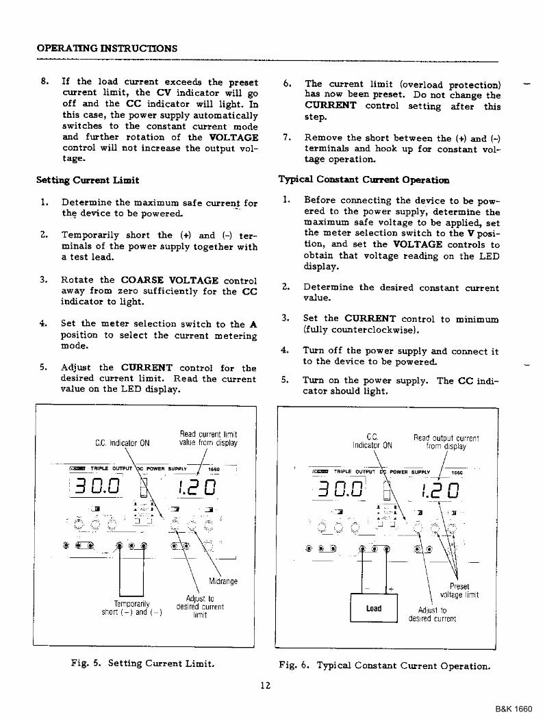
SettiDg CurtcDt LiDit
1. DeterEine the r:taxiEum safe curreDt fo!the deeice to be powered-
2, Telopolalily short the (+) arld (-) ter-D:ibals of the powe! supply togethe! witha test lead,
3. Rotate the COARSE VOLTAGE contlolaway froE zelo sufficiently fo! the CCindicato! to ligbt.
4. Set the Eete! selection s\ritch to tbe Aposition to select the cuflent loeteringrnode.
5. Adjust rbe CI'I{RENT contlol {or thedesi!€d curlent liEit. Read the culleDtvalue od the LED display.
C.C Indcalor 0NRead current lmtvalue lr0m d splay
6. Tbe cullent libit (oeerload plotectioD)has now bee! pleset. Do not change theCITRRENT codttol settiDg atter thisstep.
?. Rebove the sbolt betweeD the (+) aDd (-)telminals and hook up for constalt vol-tage opelation.
Typical CoDstrnt Cr!!€ot O!€ratioD
1. Before connectiEg the device to be pow-eled to the power supply, detelBiDe theEaximurb saJe voltage to be applied, setthe mete! selection switch to the V posi-tion, alld set the VOLTAGE controls toobtaiD that voltage reading on tbe LEDdisplay,
2. DetelEine the desired constant cu|nt
3. Set tbe CURR.ENT control to ErmEum(f ully counterclockwise).
4. Turn oif the power supply and connect itto t}|e device to be powelea!.
5. Tula on tbe power supply. Tbe CC indi-cato! sbodd light.
nL)l n
IJ
Temporariyshort {-) and ( )
@t
fulrdrange
r m i
c cndicalor 0N lrom drsplay
B O : 3
volage mt
0es reil cufrenl
Fig. 5. Setting Curlent LirDit. Fig. 6. TlTical Codstant Crrrent Opelation.
B&K 1660
OPERATING INSTRUCTIONS
6. Set the Eete! selection switch to the Aposition to obtair the curlent Eeteringlllode.
?. Incease the CURRENT control settitrguntil the desired constant cu!!€nt valueis read on the display, or set the culentIimit in advance (befole connectidg theload) as prescribed earlier in the "Setting
Cullent Limit" procedr.ue
8. If the load culrent clroPs belo\t the con-stant cullent value' the CC iidicatorwill go off aJId the CV indicato! wiutigbt. In tlis case, the por'ei suPPlyautooatically switches to the constantvoltage 6ode, aDd further rotation of theCURRENT control will not increase theoutput crflent'
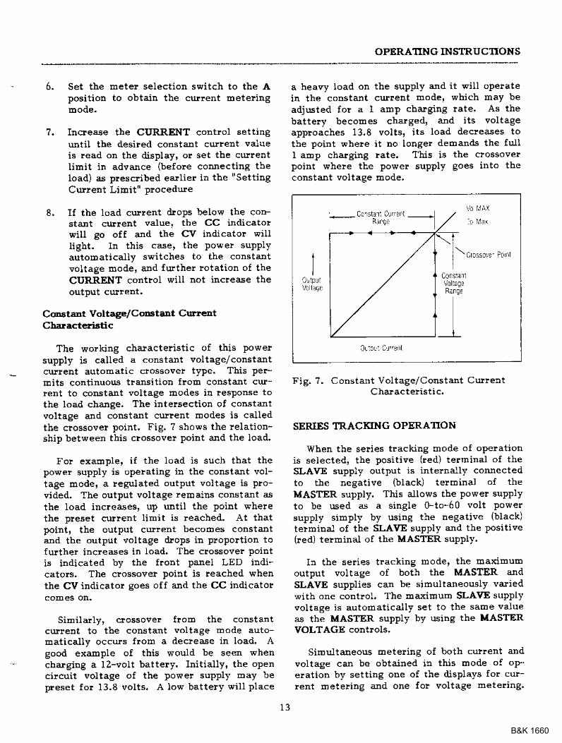
C€Estant Voltage/CottetaDt CurentCharactedstic
The working charactelistic of this powersupply is called a constaDt voltage/constantcutleDt automatic clossover t'?e. This Per-rnits continuotrs tlansition floh constant cur-rent to constant voltage modes in reslonse tothe load change. The intelsection of constantvoltage and constant crrllent modes is calledthe crossover point. Fig. 7 shows the relation-sbip between this crossove! poirt and the load.
Fo! exadple, if the load is such that thepowe! supply is opelating in the constant vol-tage roode, a reguiated output vol tage is pro-vided, The output voltage lemairs constant asthe load iDcreases, up uDtil the point v,thelethe preset cutlent Iimit is reached. At thatpoint, th€ output cu.}lent becohes constantand the output voltage drops in Fopoltion tofurthe! increases in load, The crossove! pointis indicated by the front panel LED indi-cators. The clossovei point is reached whenthe CV indicator goes off and the CC indicator
SiEilallv. crossove! flom the constantcurlent to the constant voltage mode auto-matically occuls fror! a ileclease in load' Agood example of this would be seen whencharging a lz-volt battery. Initially' the oPencilcuit voltage of the powe! suPPly Eray bepreset for 13.8 vol ts. A low battery wi l l p lace
a heavy load on the supply aJId it will opelateiE the constant culredt mode' which may beadjusted for a I aIlP chargitlS tate. As thebattery becomes charged' and its voltageapploaches 13.8 volts, its load decleases tothe poiDt where it no longer deoands the fullI aElp charging !ate. This is the clossoverpoint whele the power supply goes into theconstant voltaee mode.
1I
___-L
Fig. ?, Constant Voltage/Constant CutlentCharacte! ist ic.
SERIES TRACKING OPERATION
when the selies tracking mode of oPelationis selected, the positive (red) telrDinal of theSLAVE supply output is internally connectedto th€ negative (black) telmillal of theMASTER supply, This allows the Powe! supPlyto be used as a single 0_to-60 volt Powersupply simply by using the negative (black)
telmina.l oI the SLAVE supply a]Id the positive(!ed) telminal of th€ MASTER supply.
In the selies tracking mode, the ltraximumoutFut voltage of both the MASTER andSLAVE supplies can be sirDultaneously variedwith one coDtroi. The ma-yiEluro SLAVE supplyvoltage is autoaatically set to the sarne valueas the MASTER supply by using the LASTERVOLTAGE contlols,
Simultaneous metelillg of both current andvoltage can be obtaided in this mode of oP_eration by setting one of the displays for cur-rent Eleteling ajld one fo! voltage metering.
B&K 1660
OPERATING INSTRUCTIONS
In this case, the output voltage (across the twosuppliesi is actually double the displayedvalue. For example, if the MASTER disptay isset fo! voltage meteling ard the SLAVE dis-play for current oetering, the output voltageacloss the MASTER positive (red) tellninaf andthe SLAVE negative (black) telmiDat would bedouble the reading on the MASTER LED Die-play (since both supplies are putting out thesarDe voltage), The actual output currentwould be the value lead frob the SLAVE LEDDisplay (since the t,ro supplies are wiled in inseries, current flowing through each supplyEust be equal).
1. Set the power suppties to the TRACKINGSERIES mode by engaging the leftTRACKING switch and release the liehtTRACKING switch.
Z. Set the (F30 V/,t-6.5 V switch to theG30 V position the MASTER A/V switchto the V (voltage meteling) position, andthe SLAVE A/V switch to the A (currentEetedtlg) position,
3. Set the SLAVE CURRENT control to thefully clockwise position. The inaximumcurlent is set using the MASTERCURRENT control. Follow the in-st luct ions fo! "Sett ing Clrrent Limit"( INDEPENDENT USE OF "MASTER" OR'SLAVE" SUPPLY sect ion ol this manuatlusing the MASTER CURRENT control.
NOTEBecause the supplies are beingused in sedes, eithe! CURRENTcontlol can be used to s€t maxi-dlurh crl}Ient. II desired. theMASTER CURRENT control cabe rotated fully clockwise andthe SLAVE CURRENT controlcan be us€d to adjust the maxi-rnum curlent value. Becausecurrent through the two suppliesmust be equal when they arebeing used in se es, the lowestCURRENT control setting wiuset the rnaxihum output cu!!ent.
4. Adjust the output voltage to the desiledlevel using the MASTER VOLTAGE con-trols (rerel :)ber that the actuar ourDur
voltage is double the reading on theMASTER LED Display).
Turn olt the power suppty ard theequipment to be powered during hook-up.
Connect the positive polarity of thedeqice being powered to the led (+) te!-minal of the MASTER poweF supply,
Connect the negative polality of thedevice being poweled to the black (-/terminal of the SLAVE powe! supply.
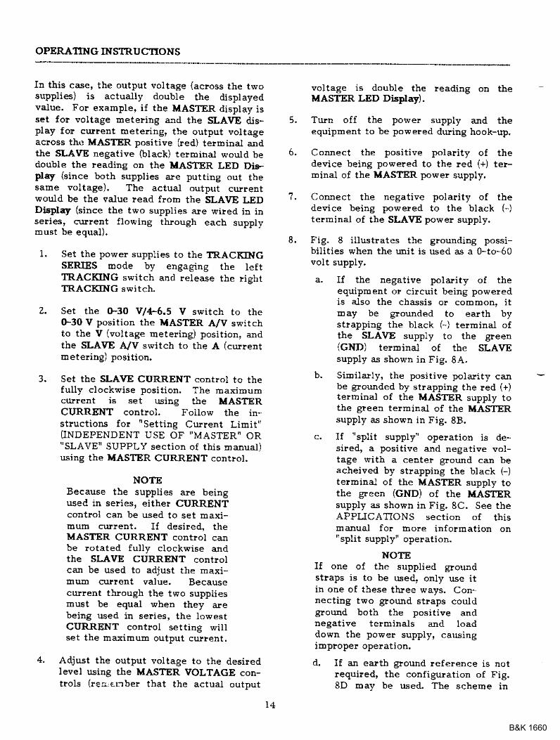
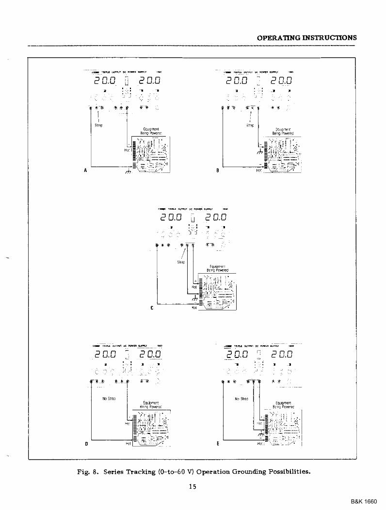
Fig. 8 illustrates the grounding possi-bilities when the lmit is used as a 0-to-60volt supply.
a- If the negative polality oI theequipment or circuit being powe!edis also the chassis or common, itmay be grounded to ealth bystlapping the black (-) terminal ofthe SLAVE supply to the green(GND) terr'inal of the SLAVEsupply as shovD in Fig. 8A,
b. SiEilallyr the positive polarity caJIbe glounded by strapping the red (+)teirDiDal of the MASTER supply tothe green telminal of the MASTERsupply as shown in Fig. 88.
c. lf "split supply" operation is de-sired, a positive and negative voFtage with a center ground car beacheived by stlapping the black \-/t€rminai of the MASTER supply tothe green {GND) of the MASTERsupply as shown in Fig, 8C. See theAPPLICATIONS section of thismanual for rhore infolEation on"split supply" operation.
NOlEIi one of the supplied $oundstraps is to be used, only use ithr one of these three ways. Con-necting two ground straps couldground both the positive andnegative terminals and loaddown the power supply, causing
d, If an ealth gtound lefeience is notrequired, the configuration of Fig.8D may be used. The scheroe in
1 .
8 .
5 .
6 .
B&K 1660
OPERATING INSTRUCTIONS
e 0.0
' r , : . ' t :
Fig. 8. Selies Tlackirg (0-to-60 v) Opelation Glou.nding Possibilities.
B&K 1660
OPERATING INSTRUCTIONS
Fig. 8D shou.ld also be used whele itis not }crown wbetber tbe chassis iscohmon with eithe! the positive olDegative polality.
e. If the chassis o! comEon of theequipEent being poweFed is separ-ate tlol]l both the positive and neg-ative polality powe! inputs, use theconlrection shown in Fig. 8E.
9. Obselee proper polarity, If the cilcuitbeing powered is not equipped with re-verse polatity protection, dabage to thecilcuit can lesult flom leverse polality.Use color coded hook-up leads, such asthe sets supplied with the power supply,for cotrvenience in identifyiEg polalitt,led fo! (+) a:rd black for (-).
10. Make sure that the hook-up leads ollersufficieDt curlent capability and low !e-sistance between the power supply andthe cilcuits being powered. The hook-upIeads supplied .lvitb th€ power supply arerated fo! 3 amps,
PARALLEL TRACKING OPERATION
In the palallel tracking mode of operation,both supplies are strapped togethe! (in paral-lel), This auows for a 0-30 V supply with a 4ardp current capability. Onty the IIASfiRoutput telminals are used fo! parallel tlackingopelatioD. ln the paldlel tracking mode, theSLAVE supply output voltage and cu.rreDttlack the MASITR supply output voltage and
1. Set the power supplies to the TRACKINGPARAILEL mode by engaging bothTRACKING switches.
2, Set the o-30 v/4.5 v switch to the(F30 V position, tbe MASTER A/V switchto the V (voltage Eeteling) position, andthe SLAVE A/V switch to the A (currentmeteling) position. Output vottage wiUnow be read f!o@ the I|ASTER LED Dieday. Output culrent is exactly doubl€the value lead from the SLAVE LED Dis-play (because each supply is providingtbe saBe ahount of curlent).
3, Because both voltage and cuirent of theSLAVE supply tlack the MASTER supply,
the r]Iaxibum cr.EreDt and goltaee ale setusiog tbe MASTER controls. iJsiag theMASTER supply output jacks, follow theiDstluctions {o! "Setting Cullent Limit'CINDEPENDENT USE OF "MASTER" OR'SLAVEI SUPPLY palaglaph of this sec-tion). RerDeEber that the actual currentoutput at the MASTER supply outputjacks is double the leading oD the SLAVErcD Display.
Adjust tbe output voltage to the desiledlevel usidg the UASTER VOLTAGE con-t!ols.
Turn off the powe! supply and theequipEent to be powered during hook-up.
Connect tle positive polality of tbe de-vice beiDg poweled to the led (+) te!-E:inal of tbe MASTER powe! supply.
Connect the negative polarity of the de-vice b€irg liowered to the black (-) ter-minal of the MASTER powe! supply.
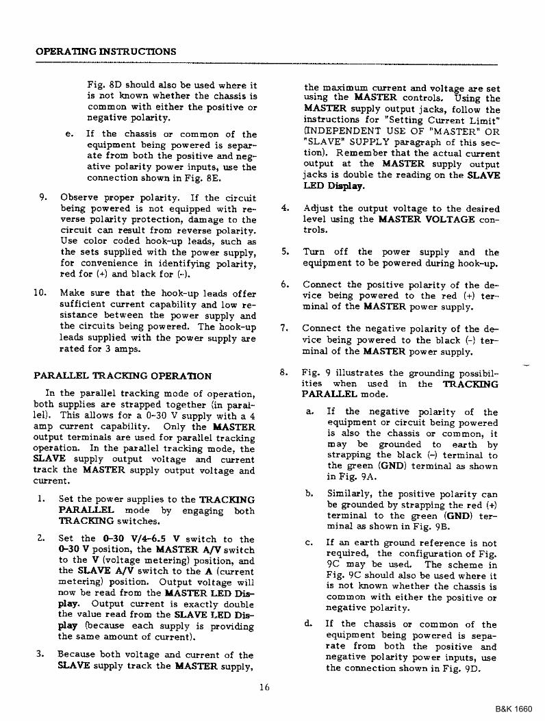
Fig. 9 iliustlates the grounding possibit-ities when used in the TRACKINGPARAIIEL mode.
a. If t}te negative polality of tbeequiploent or cilcuit being poweredis also the chassis or comloon, ittDay be glounded to eatth bystrapping the biack (-) terminal tothe green (GND) telminal as shownin Fig. 9A.
b, SiEilarly, the positive polarity canbe gloulded by stlapping the led (+)terminal to th€ gleen (cND) te!-minal as shown in Fig. 98.
c. If an ealth ground leference is notrequire4 the corfiglration of Fig.9C Day be used. The scheme rnFig. 9C should also be used where itis not known v,/hether the chassrs rscommon with ei the! the posit ive o!negativ€ troIarity.
d. II the chassis o! coErDon of rneequipment being powered is sepa-rate from both the positive andnegative polarity power inputs, usethe connect ion shotrh in Fig. 9D.
8 ,
7 .
6 .
l 6
B&K 1660
OPERATING INSTRUCTIONS
r 5 . O r a c ! t 6 . D
d in i lri
| [J.U ! 'r-.r.c.rI t- l-1 I I E B
t a i
Fig. 9. Parallel Tracking Operation Grotmding Possibilities.
t 7
B&K 1660
OPERATING INSTRUCTIONS
lt t n n f n c n
t t u J . rJ
ga:.1
10 .0 ! 0s .0 3 [ .C
E 3 , r o
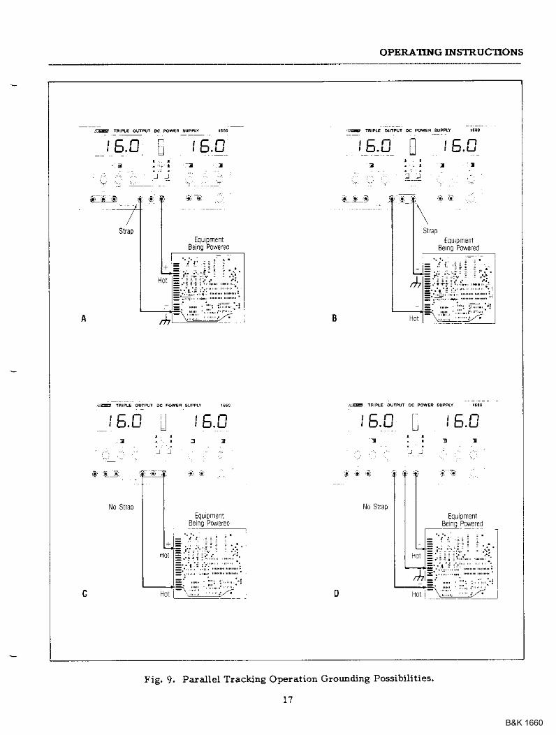
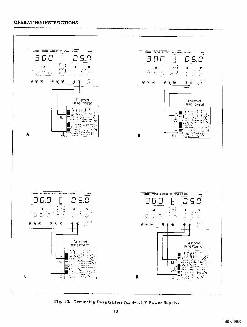
Fig. 10. clounding Possibilities for 4-6.5 V power Suppty.
1 8
B&K 1660
OPERATING lNSTRUCTONS
9, ObseNe prope! polarity. If the circuitbeing po\rered is not equipped with re-verse polarity protectior, darDage to thecircuit can }esult from reverse polarity.Use color coded hook-up ieadsr such asthe sets supplied with the powe! supply,Ior convenience in identifying polarityired for (+) and black fo! (-).
10. Make sure tlat the hook-up leads offersufficient c1rrlent capability and low !e-sistadce between the power supply andthe circuits being poweled. The hook-upleads supplied with the povrer supply arelated for 3 aDops. 10-amp test leads areavailable as an optional accessory.
+6.5 V POWER SUPPLY OMRATION
The ,t-6.5 v supply plovides a 4.0 to 6.5 vDC output with a 5 aEp cul ient capacity. Thesupply is ideal fo! use with TTL circuits.
1, Set t]te G30 v/+6.5 v switch to the1F6.5 V position and the MASTER A/Vswitch to the V position. This sets theMASTER/.1-6.5 V Display to show outputvoltage of the ,{-6.5 v supply.
2. Using the Voltage Leyel C@Eol to ad-just the output voltage of the 4-6.5 Vsupply to the desiled level.
3. Turn off the powe! supply alld theequipment to be pos'e!ed during hook-up.
4. Connect the ?ositiv€ polality of the de-vice being powered to the }ed ( l ter-minal of the ,F6.5 V supply.
5. Conn€ct the negative polarity of the d€-vice being powered to the black (-) ter-minai of the !F6.5 V supply.
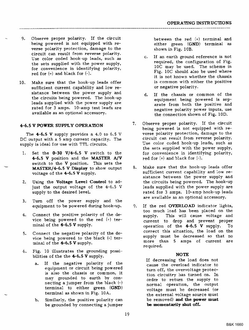
6. Fig. 10 i l lustrates the grounding possi 'bilities of the the 4-6.5 V supply.
a. I f the negat ive polal i ty of theequipment or cilcuit being poweredis also the chassis or coDomon, itrEay gloulded to earth by con-nect ing ajumper from the black G)terEinal to either geen (GND)termiDal as shown in Fig. 10A.
b. Similarly, t}le positive polarity canbe glounded by connecting a juEper
between the red (+) terEinal arldeither gteen (GND) teltninal asshown ir1 Fig, 10B.
c. If an earth glound refelence is notrequiFed. the conf igulat ion ot Fig.IoC Eay be used. The scheme inFig. IoC should also be used wherei t is not known whetheF the chassisis common with either the positiveor negative pola.!ity.
d. If the chassis or collrlon of theequipment being powered is sep-alate f!o!D both the positive andnegative polarity powe! inputs' usethe comect ion shown of Fig. 10D.
Obs€Ive prope! polarity, If the circuitbeing powered is not equipped v'ith re-verse polal i ty protect ion' damage to thecircuit can result floe leverse Polarity.Use color coded hook up leads' such asthe sets supplied with the power supply'for convenience i$ identifying polarity'red for {+) aDd black for (-) ,
Make sule that the hook-up }eads offersufficielt cujlent capability and low !e-sistance between the powe! supply andth€ cilcuits being porreled. Tbe hook-upIeads supplied with the power supply arelated for 3 aftps. 10-a6p hook-up leadsare available as an optional accessory,
If t}le red OVERLOAD indicato! lights,too rouch load has been placed on thesupply. This will cause voltage andcurrent to illop and prevent properoperation of the +6.5 v supply. Tocorlect this situation, the load on thesupply must be decreased so that nomole than 5 amps of culrent aleiequi!ed.
NOTEIf decreasing the Ioad does notcause the ovelload indicator totuln off, the ovelvoltage protec-tion cilcuitry has turned on, lno!de! to leturn lhe supply tonorrDal ope!ation, the outputvoltage must be decreased (o!the extelnal voltage source (oustbe removed) ad tle poF€r Enstte EoEentarily shut off.
1 .
8 .
9 .
r.9
B&K 1660
APPLICATIONS
GENERn'L
Tbe Model 1660 power supply bas a verywide valiety of applications iu electrical a$delectlonics servici.Dg, engineering laboratorie6,hanuf actulitrg altd testiDg f acilities, scbools,and hoEe hobbying, Tbe Maste! and Slavepower supply outputs are fully adjustable from0-to-30 volts and G-to-z aEps and the 4'6,5 Vsupply is fu.lly adjustable fron 4-tc'6,5 V witha curlent capability ot 0-to-5 aEps. TNs flex-ibility Drakes it suitable for Erost applicationsrequiring a dc powe! soutce.
EI.ECIRONICS SERVICING
Most electronics tloubleshooting and repairis performed on a test benclr This powe!supply can plovide the dc powe! soutce to op-elate a Ecodule o! circuit boald on the testbench when it is removed frol! its pareatequipoent. lt can be used to power poltable,batterfopelated equipEent and check the ef-fect of Iow battery voltage. It can powe! ve-hicular equipdeDt such as tape players, autosound sFterls, CB ladios, etc. on th€ testbedch. Parallel tracking supplies up to 4aEps, adequate surge cullent fo! eost vehicu-la.! equipEent.
Most autoEobiles aDd otber vechicles uselZ-volt electrical systeEs. Although the elec-trical systerE is normally referled to as a 12-volt systeE, actual battely voltage when fullychalged is apploximately 14 volts. The powersupply may be set to 14 volts fo! servicitrgequipment lrolD vehicles with lz-volt electri-cal systeEs. SoEie trucks use a Z+volt elec-trical systeE; bench testiag of equipEentfroE these systeEs should be pelforhed at 28
Soloe serviciug applications requile the in-jection of a vaiable dc voltage Io! celtaintests, such as checking the effect of AGC biasin a television receive!. This lequires an iso-lated dc powe! supply, such as the Modei
1660, The equipment being tested Eay co.-tain its own power supply and operate floE acpowe!. A dc voltage hay aheady be plesentin the cilcuit. Otre polarity of the powersupply output is floated to an applopriatepoint in the cilcuit, such as the eljlitte! of atlarsisto!. The other poladty of tle powersupply output is then applied to alrothe! pointin the cilcuit, such as the base of that traJl,sisto!, Varying the powe! supply voltage thenvades tbe dc bias on the stage, ard the effectstDay be noteal A series lilrlitiDg lesistor isoften used to protect the circui ts froh oveFdissipation.
ELECTROMCS MANUFACTI'RING
In electronics oa[ufactuling facilities, thepower supply is o{ten used as a dc powe!soulce while testing aIld adjusting modules,subassexoblies, and cobplete tmits in the pro-duction and asseiobly alea o! in the qualitycontrol a!ea, The instluoent calr be used inincoming inspection as a dc power souice fortesting pulchased cor:tponents and subasser:t-blies.
This power supply is palticularly weU suitedIoi roanufactuling applications because of itsease of opelation and its continuous dutyrating. When load curlent or total Fower dis-sipation ale aoong the maiD characteristics tobe measure4 the total load current and vol-tage are easily displayed on the LED display.The current limit can be set so that all unitsivbich do not lDeet the load culleDt specifica-tior will cause the CC indicator to light, aJIdthe unit can be lejected.
ELECTRONICS DESIGN LAB
The tecbnician or enginee! working in anengineeling laboratory requiles a dc powe!supply to powe! bleadboatd and plototype ci!-cuits, This power supply is ideal because rrbonitols output cuFent ajld voltage, limits
zo
B&K 1660
APPLICAIIONS
current to trEotect the circuit, is adjustableoger a wide range, alxd has excellentlegulatioo aDd very low ripple.
Use of the instrumeDt ia an eDgiDeeringIabolatoly is vely similar to tbat desoibed forservicitrg electlonics equipEo ent aDd rDodules,except that lowe! currents tDay be pleva.lentwheD powering iodividual circuits. The cu|-ledt liEitiDg feature is vely valuable iD thisapplication because it can plotect u.nplovencircuits froEr damage.
EIICTROMCS EDUCATION
The student in an electlonics culriculuEdEay use the powe! supply fo! powering equip-Eent and cilcuits as pleviously described forall otbe! applications. In additioD, the poweisupply can be used in the classlooE laboratoryto conduct expedhents in furdamental elec-tlonics. In lealning ohE's law, fo! exaeple,the relationships of resistancet current, andvoltage are easily derDonstlated by the use ofa po\re! supply.
BATTERY CSARGnIG
The power supply can be used as a battelychalge! to restore the charge in rechargeablebatteries such as lead-acid, nickel-cadmium,and soEe alkaline t]?es. Refe! to the battelyxoanuJacturerts charging specifications fo!prope! voltage and current settingE. ChargingiDformation is soloetioes plinted on the bat-teries. Battery charging, at least initially,requles the constant cutlent mode of opet-ation. Before connecting the powe! supply tothe battery, preset the VOLTAGE controls tothe fuUy chalged terEinal voltage specified byttre battely Eanufactule!. Tuttl off the powe!supply wbile connecting the battely, Observeplope! polality and connect as tor constantculrent operation. Adjr.Et the CITRRENT con-tlol fo! the Eaxixoum chalging curlent speci-I ied by the battely hanufacture!, [ f themanmum charging curlent is gleate! than thepowe! supply's maxiroun load current, set theCURRENT coDtlol to EaxiEuxo). The CC in-dicator will light and the battely will chargeat the preset curlent lirbit. As the battelyapploaches full charge, its terEina.l voltage
will apploach tbat of the power supply outputand tbe charging curleut will taper off, Thepower supply loay autoEatically switch to CV(constant voltage) opelatio!. When tbisoccurs, the powe! supply will continue to pro-eide a trickle charge.
SPIJT SUPPLY
Frequently, "split powe! supplies" are re-quired fo! aEplifier and other electro[ic ci!-cuits. The Model 1660 is ideally suited fo!"split powe! supply" opelation. TNs supplycaJI be coDfiguled to provide two positive vol-tages with a corDrDon negative, two negativevoltage6 with a commoD positive, ol otre posi-tive and one negative with a common ground'In addition, each of these configruations canbe obtained with identical o! diffeline vol-tages.
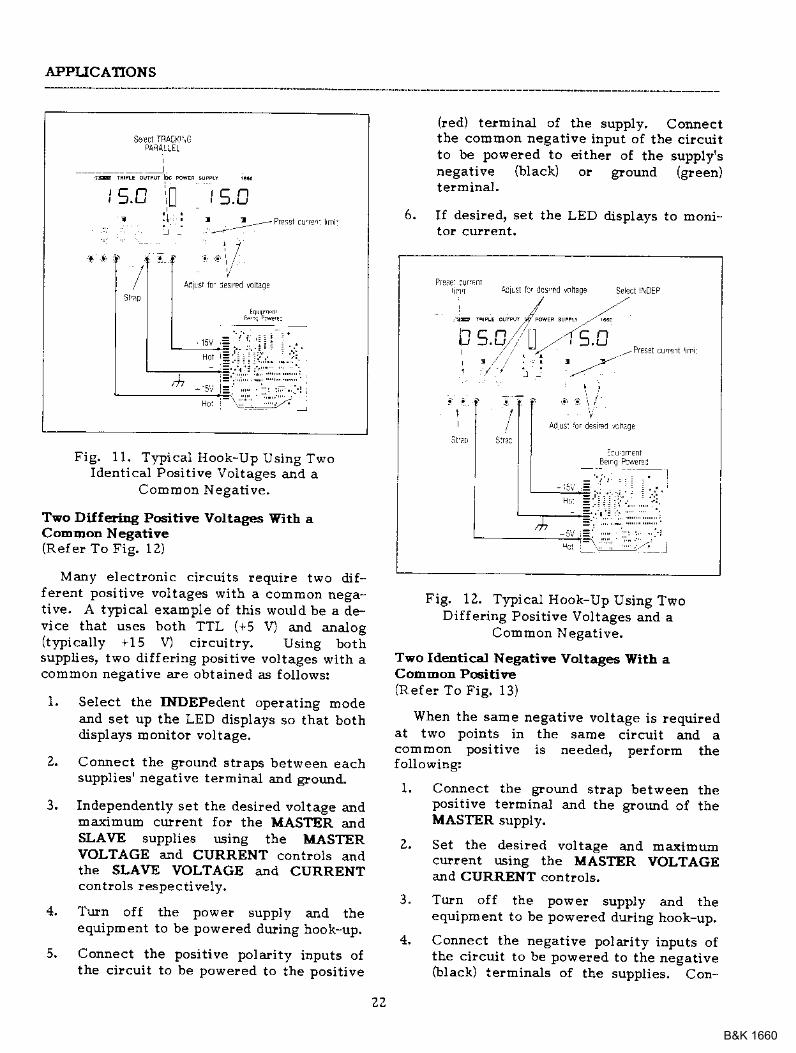
Teo ldeDtical Pcitive Voltages With aCoDEoD Negative(Refer To Fig, 1l)
Sol:]e electlonic equipDent !equiles twoidertical positive voltages with a cotDhonnegative, A good example of this would be aaigital ca.! clock whele there a-!e two +12 voltinputs and a collEon negative. Using bothsupplies in the para.llel tracking rllode wouldplovide the siEplest hook-up anal opelatior:.This t}?e of 'split supply" operation is ob-tained as follows:
1, Connect a glound stlap between theMASIER supply's negative terEinal andglound.
Z. Set the desiled voltage &d maximumcurlent using the MASTER VOLTAGEand CURRENT controls.
3. Turn o{f the power supply and theequipment to be powered during hook-up.
4. Codnect the positive polarity inputs ofthe circuit to be poereled to the positive(red) terminals of the supplies and con-nect th€ corohon negative itrput of thecilcuit to be poweled to the MASTERsupply's negative (black) or gound
Green) telminal.
z l
B&K 1660
APPLICATIONS
Sed rRACr \G
]E ;tu; ;qPq L; rcEi ,**,
! t r n n t C nL | ) t )
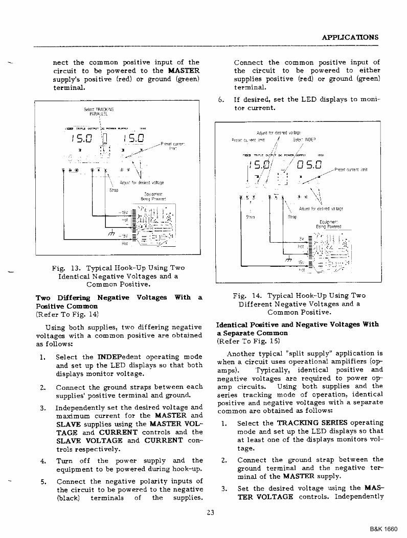
Fig, 11. T}?ical Hook-Up Using TwoIdent ical Posit ive Voitages anC a
! v u r ! u ! r r c t s d u v c .
Two Dilf€ridg Positiye Voltages With aCoEood Negative(Refe! To Fig. 12)
Many electronic circui ts lequi le two di f-ferent posi t ive vol tages with a common nega-tive. A tFical example of this would be a de,vice that uses both TTL (+5 V) and analog(t}?ical ly +15 V) ci lcui try. Using bothsuppt ies, two di f fer ing posit ive vol tages with acommon negat ive are obtained as fol lows:
l . Select the INDEPedent opelat ing modeand set up the LED displays so that bothdisplays Donitor voltage,
Z. Coinect the ground straps between eachsuppliesr negative terminal and glound.
3. Independentty set the desired voltage andmaximulo cuirent for the MASTER andSLAVE supplies using the MASTERVOLTAGE and CURRENT contlots andthe SLAVE VOLTAGE ald CURRENT
4. Turn off the power supply and theeqriipment to be powered during hook-up,
5. Connect the positive polarity inputs ofthe circui t to be powered to the posit ive
(!ed) terrninal of the supply, Connectthe cor!6orl negative input of the cilcuitto be powered to either of the supply'snegative (black) or ground (8}een)terminal.
If desired, set the LED displays to moni-6 .
Fig. 12. T}?ical Hook-Up Using TwoDif fel ing Posit ive Voltages and a
Comlr]on Negat ive.
Two Ideutical Negative Voltages With aComEon Positire(Refe! To Fig. 13)
When the same negative voltage is requiredat two points in the same circuit and acommon posit ive is needed, pelform thefol1o\ring:
1. Connect the gro'$d strap between thepositive terrninal and the ground of theMASTER supply.
Z. Set thF dFsi led vol tage and maxiEumcurlent using the MASTER VOLTAGEand CURRENT controls.
3. Turn off the powe! supply and theequipmeDt to be poweled during hook-up.
4, Connect the negative polarity inputs ofthe circuit to be poweled to the negativefblack) terhinals of the supplies. Con-
zz
B&K 1660
APPIICATIONS
nect the coroEon positive input of thecircuit to be powered to the LASTERsupply's positive (red) or ground (green)terminal.
Fig. 13, Tnical Hook-UP Using TwoIdentical Negative voltages and a
ComBron Posit ive.
Two Dilfering Negative Voltag€s With aPcitive CoEmod{Ref er To Fig. 141
Using both supplies, two differing negativevoltages with a common positive ar.e obtainedas follows:
1. Select the lNDEPedent operating Eodea.nd set up the LED displays so that bothalisplays Eonito! voltage.
2. Connect the ground straPs bet\teen eachsupplies' positive terminal and ground-
3, Independently set the desiled voltage andma-,.imulrl current fo! the MASTER andSLAVE supplies using the MASTER VOL-TAGE aJld CURRENT contlols and theSLAVE VOLTAGE and CURRENT con-t lols respect ively.
4. TrJI1 off the power supPly and theequipment to be po\pered dudng hook-up.
5. Connect the negative polarity inPuts ofthe circui t to be powered to the negat ive(black) terminals of the supplies'
Connect the coErnon positive input ofthe circuit to be powered tc eittre?supplies positive (red) or gtound (gree$)
termina.I.
I f desired. set the LED displays to moni6 .
Fig. 14. Tnical Hook-Up Using TwoDil ferent Negat ive Voltages and a
Common Posit ive.
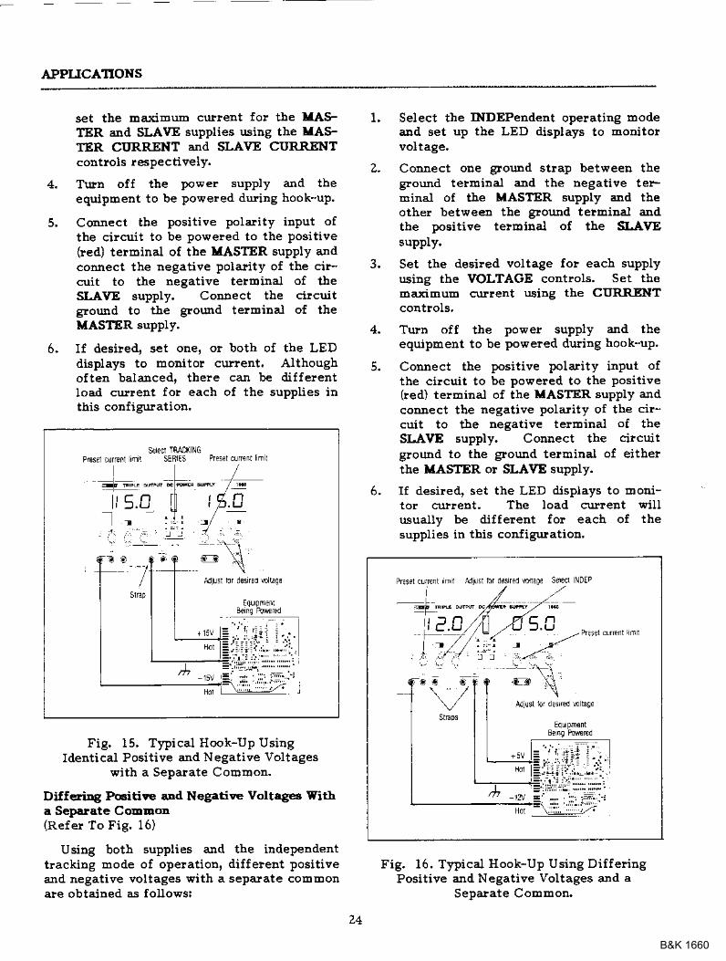
Idedtical Pcitive and Negative Voltags Witha Separate CotnDon(Refer To Fig. 15)
Anoth€r tnical "split supply" application iswhen a circuit uses operational amplifiers (op-
amps). TWically, identical positive andnegative voltages aie required to power op-amp circuits. Using both supplies and thesedes trackiBg mode of operat ion, ident icalpositive and negative voltages with a sepalatecosrmon are obtained as follows:
1. Select the TRACKING SERIES operatingmode ard set up the LED disPlays so thatat least one of the displays monitols vol-tage.
Z, Connect the ground st.aP between thegound telminal and the negative ter-minal of the MASTER suPPlY.
3. Set the desired voltage using the MAS-TER VOLTAGE controls. IndePendently
t C . ] '
t " t l
23
B&K 1660
APPLICATIOXS
set tbe EarciEum curlent fo! the llASFTER and SLAVE supplies usiug the MAs-TER CURRENT and SLAVE CURRENTcontlols !espectively.
Trlln off the power supply and theequipment to be powered dul.ing hook-up.
Connect the positive polarity inPut ofthe cilcuit to be poweled to the positive(red) terEinal of the ITASTER supply andconnect the negative polality of the cir-cuit to the neSative teroinal of theSLA\rE supply. CoDDect the circuit
Erourd to ttre ground telmina.l of theMASTER supply.
If desiled. set one. o! both of the LEDdisplays to rEoDitor cu!!ent. Althoughoftetr balalced' there can be diffelentIoad curreDt fo! each of the supplies inthis confisuration.
Select the INDEPendent opelating lDodealcd set up the LED displays to Eonitoieoltage.
CoD[ect oDe glound strap between theground teruinal and the negative teFminal of the MASTER supply and tbeother between the ground tetDtiBal andthe positive termiral of the $-AVEsupply.
Set the desiled voltage fo! each supplyusiDg the VOLTAGE coatlols. Set tbedaximuE curlent using tbe COR.R.ENTcoutrols,
Tuln off the powet supply and theequipEent to be powe?ed duting hook-up.
Couect the positive polarity input ofthe cilcuit to be poweled to the Positive(red) termina.l of the LASTER supply ardcomect the negative polarity of tbe cir-cuit to the negative telrDinal of theSLAVE supply. CoIllect the circuitglound to tbe groutrd tetEinal of eitherthe XASTER or SLAVE supply.
If desired, set the LED displays to Eodi-tor cu!!ent. The load curreDt $illusually be different for each of thesupplies in thi6 configuratiod,
Fig. 16. Typical Hook-Up Using DilfelingPositive aJId Negative Voltages and a
Sepaiate CoEmon
L
5.
6.
z-
3.
6 .
5.
SEIECI TRM( NGSEB€S Prcsl curc( mr
Fig. 15, Tnical Hook-Up UsingIdentical Positive and Negative Voltages
with a Separate CoEuon.
Ditl€triDg Pcitive and Negatiye Voltag6 Witha Seperate CoEDon(R€fer To Fic. 16)
Using both supplies aDd the iDdependenttlackiDg mode of operation, diffeleDt lositiveand negative voltages with a separate cotiEonale obtained as followsi
qdr!\ or dr\rd 4,aoP EdPn NoEP
! e.0
z4
B&K 1660
MAINTENANCE
The follo\dng instructions orefor use by quolified personnelonlt To dvoid electrical shock,do not perform @ry servicingother thotl contnined in theoperatiftg instructions uniess youore qtnlified to do so.
FUSE REPLACEMENT
If the fuse blows, the slvitch, the LED dis-plays, and al l other indicatols wil l not l ightand the po$eI suppl) wi l l not opefar-. ThFfuse should not normally open Lmless a prcblemhas developed in the Lmit . Try to determineand colrect the cause of the blowl fuse, then
replace only with a fuse of the colrectlat ing. Fo! 110 or 120 V operat ion a 5 A,250 V, 3AG fuse should be rrsed ard for 220 or240 v operat ion a 2,5 A, 250 V, 3AG fuseshould be used. The fuse is located on the rearpanel (see Fig.2).
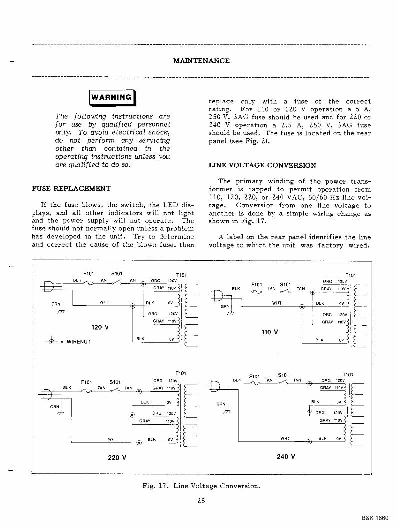
LINE VOLTAGE CONWRSION
The primaly winding oI the powe! trans-former is tapped to permit operat ion from110, 120, 220, or 240 VAC, 50/60 Hz l ine vol-tage. CoDversion l rom one ] ine vol tage toanother is done by a simple wirirg chanse asshown in Fig. 1?.
A ]abel on the rea! panel ident i f ies the l in€voltage to \ i 'h ich the unit was factory wired.
T10
T101
;;l -l f -. t fr y t, * ll -* t -
=II-
I1 1 0 V
S_ = WIFENIJI
220 V 240 V
Fig. 1?. Line Voltage Conveision.
z5
B&K 1660
MAINTENANCE
To convert to a di f ferent l ine vol tage, perfo):mthe fol lowing procedure:
1. Make sure the power cord is unplugged.
Z, Remove the case and locate the powe!t !ansfolmer,
3. Rewire the power transfolmer to the de-sired l ine vol tage as shown in Fig, 17.Insulate the ends of the bused trans-former tap wires.
4. A change in line voitage may aiso lequilea corlesponding change of fuse value.Install the corlect fuse value as listed inthe FUSE REPLACEMENT sectron.
5. Replace the cover.
6. Aff ix a label showing the correct ] in€voltage and fuse value (if changed) foithe uiit after conversion. Place thislabel direct ly over the factory label.
ADJUSTMENTS
This lmit was accurately adjusted at thefactory before shipment. ReadjustErent isrecommended only i f repairs have been madein a circui t af fect ing adjustment accuacy, orif you have a reason to believe the rmit is outof adjustment. Howeve!, adjustments shouldbe attempted only i f a 4-1lz digi t mult imete!with an accuracy of 10.1% dcv o! better isavai lable (B & K-Precision Model 2820 orequivalent).
If leadjustment is required, use the fol-lowing procedure. AU leferences to lef t andright are collect wher facing the frort oI thesupply. Locat ions of the adjustmerts areshown in Fig. 18.
Mast€r Supply Ard Master/,{-6.5 V MeteringAdjustmedts
1. Connect an accurate (10.1%) extehal4-1lZ drei t l rul t imetel to measure the dcvoltage at the output terminals of theMASTER SUPPLY.
2. Disengag€ both TRACIONG modeswitches (both switches out) so that the
pow-r supply is in rh- INDEPFnd.nt op-erat ing rDode.
Set ihe MASTER VOLTAGE controls(both COARSE and FINE) to minimum/ { , , ] L , ^ ^ , , - r 4 ! . 1 ^ . L - ' i c - l
-A.djust t r immer potent iometer VRZ04 onthe main rraster circui t board { locatedon the right side of the supply) {or areading of -15 mv r15 rDv on the mul-t imeter.
Set the MASTER VOLTAGE cont"ols(both COARSE ard FINE) to maxinum{fuIIy clockwise).
Adjust t r immer potent iometer VRZ01 onthe Dain master ci tcui t board ( locatedo! the light side of the supply) for areading as close to 31.50 volts (on them r ! l + i m p r o r l 2 < n ^ < c i } | l a
Set the 0-30 V/+6.5 V switch to the0-30 V position and the MASTER A/Vswitch to the V posit ion.
Adjust t r i inmer potent ioureter VR201 onthe master LED dispta] ' c i icui t boaid( located on the r ight s ide ot the supplybehind the MASTER LED Display) for areading of 31.50 V on the MASTER LEDDisplay.
Set the (F30 Vl1-6.5 V switch to the0-30 V position and the MASTER A/vswitch to the A posit ion.
Connect the external mult imeter acrossthe MASTER SUPPLY output terminalsto read the output cullent (so that therneter causes a short c ircui t across theterminals) a]1d adjust the MASTERCURRENT control so that 2.00 amps isread or the mult imetel .
Adjust VR60I so that the MASTER LEDDisplay also reads 2.00 amps.
Rotate the MASTER CURRENT contlotful ly c lockwise (maxinun).
A d j u s t V R 2 0 5 o n t h F m a s t e r s u p p l y c i r -cuit boald (located on the right side ofthe supply) to obtain an output current of2.05 amps (!ead on the LED disptay).
10 ,
1 1 .
tz-
3.
5.
6 .
7 .
8 .
9 .
2 6
I 3 .
B&K 1660

MAINTENANCE
ooc".",@ @ , . . .\:t
A nr r "\ --,--/ L_l L--l
Main lllaster Circll Boad As Viewed Frum tefl Side ol Supply
I
III
Fig. l8A. Locat ion Of Adiustments (MaiD Ci.cui t Boards).
Main slavP craur' Boad {s vie*ed Frcn Bighl srde ol supply
z7
B&K 1660

MAINTENANCE
I ta
7F
VB5O]
I sr
ls6
S;ve orspa,r' PanelFronl
Fig. 188. Locat ion Of AdjustEents (Meter ing And Trackiag Boards),
17 .
1 4 .
I 6 .
Set the (F30 Vk-6.5 V switch to the4-6.5 V position and the MASTER A,/Vswitch to the V position.
Connect the multimeter across tle out-put terEinals of the ,F6.5 V SUPPLY tolead output voltag€ atrd adjust tne.1-6.5 V voltage level contlol to obtam aleading of 5,00 vol ts on the mult imele!.
Adjust t r immter potent iometer VR6OZ sot}lat the MASTER/IF6.5 V LED DisprayIeaals 5.0 volts.
Set the ITASTER A/V switch to ttle Aposition,
Connect a 1 0 load (lated at 30 W ormore) across the output terminals of the,F6.5 V SUPPLY and connect tle llutti-Beter to lead the output curlent.
Adjust t}le 4-6.5 V voltage tevel controtto obtain an output of 5.00 amps (read oDthe mult iEete!) .
Adjust trirlme! potentioDeter 1,rR603 sotha.t the MASTER/4-6.5 V LED Displayalso leads 5,00 amps.
!R602 \i F60l
Vierr From Right Sid€ 0f Supply
Fig, 18C, Locat ion Of Adjustnents.
Slave Supply Aud Metering AdjustEerlts
1. Connect an accurate ( t0.1%) external+1/Z digf Eult iEeter to Eeasule the dcvottage at the output telmidals of theSLAVE SUPPLY.
18 .
20.
z8
B&K 1660
MAINTENANCE
Z. Disengage both TRACKING modeswitches Goth sFitches out) so that thepower supply is in the lNDEPerdent op-erat ing dode,
3. Set the SLAVE VOLTAGE contlols (bothCOARSE and FINE) to nrinillruEl lfullycounte!clock\rise).
4. Adjust trirbE:e! potentiorDete! VR204 onthe Eain slave circuit boald (located onthe left side of the supply) for a readingo{ -15 mV t15 mV on the mult imeter,
5. Set the SLAVE VOLTAGE controts {bothCOARSE and FINE) to maximuE ({ullyclockwise),
6. Adjust t r immer potent iom€ter VR201 onthe Eain slave cilcuit board (located onthe left side of the supply) fo! a readingas close to 31,50 volts (on the rnult i -mara r l . . n ^ac i l a l a
?. Set the SLAVE A/V switch to the V po-si t ion.
8. Adjust tlirlldrer potentioEeter VR201 onthe slave LED display circuit boald (lo-cated on the left side of the supply be-hind the SLAVE LED Display) lor areading of 31.5 V on the SLAVE IlDDisplay.
9. Set the SLAVE A/9 swi'tch to tbe A po-si t ior.
10, Short the SLAVE SITPPLY outputte!minals together.
11. Rotate the SLAVE CURRENT controlful ly c lockwise (maximuo).
12, Adjust vRZ05 on the slave supply circuitboard ( located on the lef t s ide of thesupply) to obtain an output curi€nt of2.05 amps (read on the LED display).
Slave Setie* Tracking Adjustm€nt
1. Set the supply to the TRACKING SERIESErode by engaging the left TRACXINGswitch and releasing the rightTRACKING s\ritch.
Z. Set the SLAVE CIIRRENT control tomidrange and set both th€ COARSE andFINE MASTER VOLTAGE controls tominimua (f ul ly counte!clockwise).
3. Connect the multiEleter to the MASTERSUPPLY outputs and measuie the vol-tage.
4. Discolnect the multiEeter trom theMASTER SIIPPLY outputs and connect itacross the SLAVE SUPPLY outputs.
5, Adjust t r iBlDcer potent iomete! VRZ02 onthe main slave cilcuit board (located onthe left side of the supply) to obtain theexact saEre reading fo! the SLAVE SI'FPLY output as was present at the MAS-TER SUPPLY output (e.9., if the maxi-mum MASTER SUPPLY output voltage is-15.7? mV adjust VRZoZ to obtain aroutput vol tage as close to -15.?? mV attbe SLAVE SI'PPLY as possjble).
6. Set the SLAVE CURRENT control tonidranee and set both th€ COARSE andFINE MASTER VOLTAGE cortiols tomaximum (fuuy clockwise).
7. Connect the l]lultimeter to the MASTERSUPPLY outputs and measule the vol-tage.
8. Disconnect the mult imeter f .om theMASTER SITPPLY outputs and connect itacloss the SLAVE SI'PPLY outputs.
9. Adjust VR501 (Iocated at the center olthe lo\rer flont panel circuit boald - be-hind the POVER and TRACKNGswitches) unt i l the vol tage read f lom themult imeter is the same as i t was acrossthe MASTER output tefminals. Retumthe mult imeter to the MASTER outputtelminals and verify that the output vol-tage is ident ical . I f not i repeat this step.
+6.S V Soppry O""'load Tbreshold Adjustbent
1. Set the (F30 v/4-6.5 v switch to the,F6.5 v position and set the MASTERA/V slritch to the A position.
Z. Connect the multimet€! across the,F6.5 V supply output telminals,
z9
B&K 1660
MA]NTENANCE
6.
1 0 .
1 1 .
12.
3 .
'7-
5 .
Adjust the .4-6.5 V Voltage CoDtrol tomaximum (ful ly c lockwise).
-Adjust VR405 on the main master circui iboard ( Iocated on the r ight s ide of thes u p p t y t o r a r . a d i n s n f A . 5 n - 0 . 0 . V o hthe display.
Adjusi ,1-6.5 V Voltage Control tominimum (4 v).
Short R405 and VR405.
Preset VR404 ( located or the ci?cuitboard mounted on the heat sink behindthe trarsformer) ful iy c lockwise.
Increase voltage with front panel controlto approximately ?.00 V on displav.
Slowly adjust VR404 lmti l overvottageci!cui t just act ivates (vol iage diopsapproxrmately I V).
Use the ,F6.5 V Voltage CoDtlol to adjustthe output vol tage to 5.2 vol ts-
Tuln VR403 on the main master ci lcui tboard ( located on the r ighi s ide of thesupply) Iul l - r ' c lockwise.
Conneci a var iable load ( load must belated to handle a power of at leasi 30 Wl
across the ,1-6.5 V supplv outprrt termrr 2 " F . r : d i u q t ' r e l . r r q - t l . . t t l eMASTER LED Display shoes an outputcurrent oI exact lv 5,35 A.
13. Adjust VR403 couterclockwise ul t i l theoutput vol tage {read frorn the drul t i -meter l drops by 5 to 6 mv.
14. Turn the 1F6.5 V Voltage Control fullycounte!clockwise (minirouEr).
15. Tuln VR40Z on the main Easter ci lcui tboard ( located on the r ight s ide of thesupply) fuUy counterclockwise.
16. Adjust VR40Z clocklvise rmti l the 5AOWRLOAD indicator first Iights.
INSTRUMENT REPAIR SERVICE
Because of the special ized ski l ls and testequipment required for instrument repair anclcal ibrat ion. manv custor.ers plefer to relvupon B & K-hecisioD for this service. Wemaintain a network of B & K-Plecision author-ized service agencies fo. this pulpose, To usethis service, even i f ihe i rstrument is nolonger under warranty, fol1ow the inst?uct ionsgiven in the WARRANTY SERVICE INSTRUC-TIONS "-. t ion of this manua . There is a nom-' n a l " h a l g . f o r i r s l r u m - n r < o u r o f l v a r r a n t ! .
8 .
9.
3 0
B&K 1660
YARRANTY SERVICE INSTRUCIONSFor U.SA- &d its Ovetseas Te!|'itodes)
1. Refe! to the MAINTENANCE section of you! B & K-Plecision instluctionmanual fo! adjustments that may be appl icable.
Z. If the above-m€ntioned does not corlect the ploblerD you ale experiencingwith yout unit, pack it securely (preferably in the oliginal calton o!double-packed), Enclose a letter desclibing the ploblem and irclude you!name arld addFess. Deliver to, or ship PREPAID (UPS plefelled in U.S.A,)to the nearest B & K-Prccision authorized service agency (see list en-closed with unit) ,
If you! list of autholized B & K-hecirioD selvice agencies bas been misplaced, con-tact your distlibuto! fo! the name of your nealest selvice agency, or wlite to:
B & K-h.ecisioa MA€ rNrER Afio{AL conp.Factory Selvice OpeEations
1,1-r) West Cortland StreetChicago, I l l inois 60635
TeI (312) 889-8870Tele:: 25-34?5
AIso use this address fo! techdcal inquiliesaJId replacement palrts orders.
B&K 1660
IIMITED ONE-YEAR WARRANTY
MA€ INTEP AflOIVAL COPP. warrants to the origidal putchase! thatits B & K-hecfuioD product, and the cohponent palts th€reot, wiu be fteeflom defects iD worklcajlship and Daterials fo! a peliod of one year florl| the da.teof Euichas€.
MA€ wrl l . wi thout charge. repau o!product o! corDponent parts upon deLivery to ancontractor or the factory service department,chase date in the fo"E of a sales leceiDt.
To obtain wallanty coverage in the U.S.A,, this ploduct Eust be legistered bycoEpleting and mailing the enclosed walrajlty registration cald to MAXI=gB & K-hecbio!, 6,1111 West Cortland Street, Chicago, Iuinois 60635 within fifteen(15) days from t}le date of purchase.
feplace, at i ts opt ion, defect iveautborized B & K-hecision serviceaccor:rpanied by ploof of the pur-
ElcloaioDs: This par'lanty does rot appfy b the ev€ot of misu5e c abu.se ol theprcduct cr as a result ol tDautholized altetations or lepairs. It is void if the 6eria.lttrrtrb€t i3 alte.ed defaced or removed-
MA\E shall Dot be liabte fo! any consequential damages, including with-out lixoitatior daloages resulting flol3 loss of use. SoEe states do not allow liEi-tation of incidental oI coDsequential daEages, so the above limitatiou or exclusioDE:ay Dot apply to you.
This warranty gives you specilic ghts and ].ou oay also have other lightswhich vary floD state to state.
Fo! your convenience we suggest you contact your B & K-hecirion distlibutor,wbo Eray be authorized to Eahe lepairs o! car lefer you to the nea-rest selvice coo-ttacto!, If warranty selvice cannot be obtained localy, please send the uDit toB & K-Pleciai@ Selvice DepaltEent, 6.lj(l West Cortland Street, Chicago, Illinois60635, properly packaged to avoid daEage i! shipment.
B & K-PrccieioD Test Instrun:ents walrants products sold only in the U.S.A. aIIdits overseas terlitories. In othe! countlies, each distributo! walrants the B & K-Pr€cbion pioducts whicl it se s,
B&K 1660

NOTES
33
B&K 1660

NOlES
34
B&K 1660
TEST INSTRUMENT SAFETY
6.
7 .
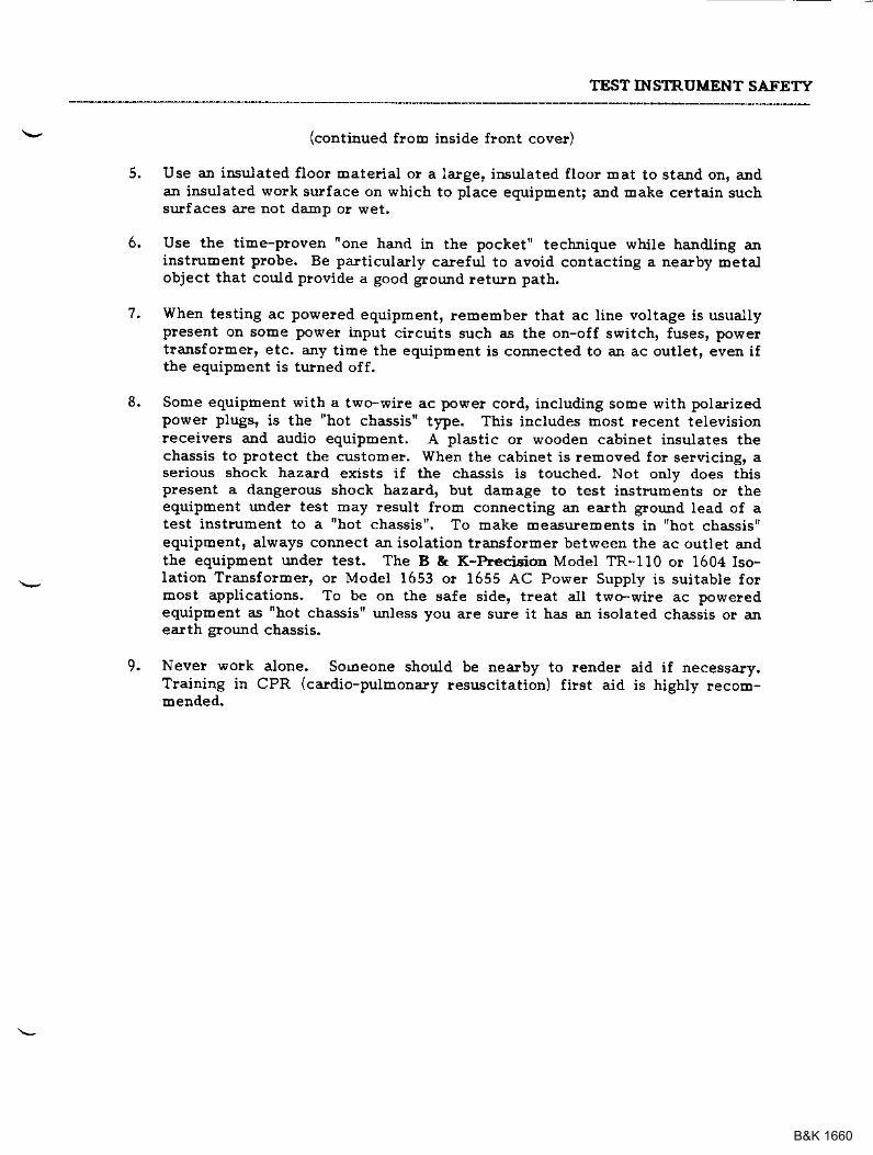
9. Never \Fork aloDe. So6eone should be nearby to render aid if necessa-ly.Tlaining ir CPR (cardio-pulEonary resuscitation) filst aid is highly lecoE-toeoaed.
(continued floDo inside flont cove!)
Use an insulated floor haterial or a large, insulated lloor Eat to stald on, andaIl insulated work surlace on which to place equipEent; and Eake certain suchsrj}faces are not da-mp o! wet,
Use the tiEe-ploven "one hand in the pocket" tecbnique while haldling aninstrubent probe. Be pa-"ticularly careful to avoid contacting a rearby metalobject that could ploeide a good ground retun path.
When testing ac poweled eqdipment, reEeEtber that ac line voltage is usuallypreseit on sorle power input cilcuits such as the on-off switch, fuses, powertlansfolme!, etc. any tirae the equiprlert is comected to an ac outlet, even ifthe equipBent is tuhed off.
Some equiphent with a two-wire ac power cord, includidg soroe v/ith polarizedpower plugs, is the "hot chassis" t1pe. This includes host recett televisionleceivers and audio equipErent. A plastic o! wooden cabinet insulates thechassis to plotect the custoBe!. When the cabinet is removed for selvicing, aserious shock hazard exists if the chassis is touched, Not only does thispresent a datrgelous shock hazard, but darlage to test instruments o! theequipment unde! test may lesult frolt connecting an ea.lth glound Iead of atest instruEent to a "hot chassis". To rDak€ measurements in "hot chassis"equipEent, ahl,ays couect ajl isolatiolr tlanstorl]ler between the ac outlet andthe equiproent unde! test. The B & K-heci6ion Model TR-110 or 1604 Iso-Iation Transfolmer, or Model 1653 o! 1655 AC Power Supply is suitable forEost applications. To be on the safe side, treat all two-wile ac poweredequipbent as 'hot chassis" unless you are sure it has an isolated chassis or ajlearth elound cbassis.
B&K 1660

$A*g(F#DE'-,JMA{SE9 INTEBIUATIOIIIAL ooFP.6470 w' Co-tb,d SL . Ct*raSs tL 60695
4ao-5a5-9-0010
O1988 MAXTEC tNTEFNAT|oNAL coRp.
Pf n l €d i n Ta iwan ROC
B&K 1660
B&K 1660
B&K 1660
B&K 1660
B&K 1660
B&K 1660
B&K 1660
B&K 1660
B&K 1660