Embed Size (px)
Citation preview
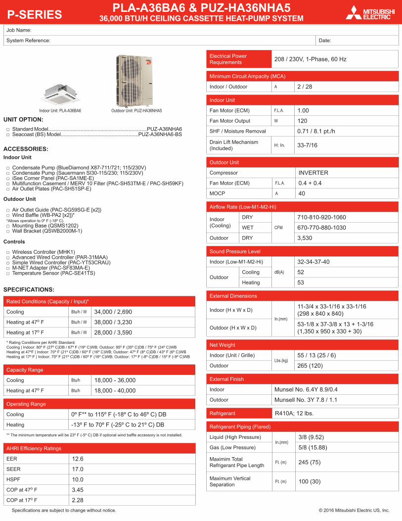
P-SERIES
Specifications are subject to change without notice. © 2016 Mitsubishi Electric US, Inc.
Job Name:
System Reference: Date:
Indoor Unit: PLA-A36BA6 Outdoor Unit: PUZ-HA36NHA5
UNIT OPTION: □ Standard Model......................................................................PUZ-A36NHA6 □ Seacoast (BS) Model.......................................................PUZ-A36NHA6-BS
ACCESSORIES:Indoor Unit
□ Condensate Pump (BlueDiamond X87-711/721; 115/230V) □ Condensate Pump (Sauermann SI30-115/230; 115/230V) □ iSee Corner Panel (PAC-SA1ME-E) □ Multifunction Casement / MERV 10 Filter (PAC-SH53TM-E / PAC-SH59KF) □ Air Outlet Plates (PAC-SH51SP-E)
Outdoor Unit
□ Air Outlet Guide (PAC-SG59SG-E [x2]) □ Wind Baffle (WB-PA2 [x2])*
*Allows operation to 0º F (-18º C). □ Mounting Base (QSMS1202) □ Wall Bracket (QSWB2000M-1)
Controls
□ Wireless Controller (MHK1) □ Advanced Wired Controller (PAR-31MAA) □ Simple Wired Controller (PAC-YT53CRAU) □ M-NET Adapter (PAC-SF83MA-E) □ Temperature Sensor (PAC-SE41TS)
SPECIFICATIONS:
Rated Conditions (Capacity / Input)*
Cooling Btu/h / W 34,000 / 2,690
Heating at 47o F Btu/h / W 38,000 / 3,230
Heating at 17o F Btu/h / W 28,000 / 3,590* Rating Conditions per AHRI Standard:Cooling | Indoor: 80º F (27º C)DB / 67º F (19º C)WB; Outdoor: 95º F (35º C)DB / 75º F (24º C)WBHeating at 47ºF | Indoor: 70º F (21º C)DB / 60º F (16º C)WB; Outdoor: 47º F (8º C)DB / 43º F (6º C)WBHeating at 17º F | Indoor: 70º F (21º C)DB / 60º F (16º C)WB; Outdoor: 17º F (-8º C)DB / 15º F (-9º C)WB
Capacity Range
Cooling Btu/h 18,000 - 36,000
Heating at 47o F Btu/h 18,000 - 40,000
Operating Range
Cooling 0º F** to 115º F (-18º C to 46º C) DB
Heating -13º F to 70º F (-25º C to 21º C) DB** The minimum temperature will be 23º F (-5º C) DB if optional wind baffle accessory is not installed.
AHRI Efficiency Ratings
EER 12.6
SEER 17.0
HSPF 10.0
COP at 47o F 3.45
COP at 17o F 2.28
Electrical Power Requirements 208 / 230V, 1-Phase, 60 Hz
Minimum Circuit Ampacity (MCA)
Indoor / Outdoor A 2 / 28
Indoor Unit
Fan Motor (ECM) F.L.A. 1.00
Fan Motor Output W 120
SHF / Moisture Removal 0.71 / 8.1 pt./h
Drain Lift Mechanism (Included) H: In. 33-7/16
Outdoor Unit
Compressor INVERTER
Fan Motor (ECM) F.L.A. 0.4 + 0.4
MOCP A 40
Airflow Rate (Low-M1-M2-Hi)
Indoor (Cooling)
DRY
CFM
710-810-920-1060
WET 670-770-880-1030
Outdoor DRY 3,530
Sound Pressure Level
Indoor (Low-M1-M2-Hi)
dB(A)
32-34-37-40
OutdoorCooling 52
Heating 53
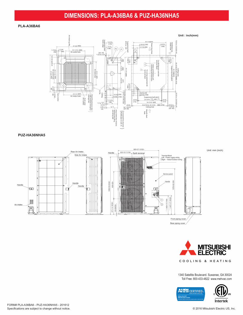
External Dimensions
Indoor (H x W x D)
In.(mm)
11-3/4 x 33-1/16 x 33-1/16 (298 x 840 x 840)
Outdoor (H x W x D) 53-1/8 x 37-3/8 x 13 + 1-3/16 (1,350 x 950 x 330 + 30)
Net Weight
Indoor (Unit / Grille)Lbs.(kg)
55 / 13 (25 / 6)
Outdoor 265 (120)
External Finish
Indoor Munsel No. 6.4Y 8.9/0.4
Outdoor Munsell No. 3Y 7.8 / 1.1
Refrigerant R410A; 12 lbs.
Refrigerant Piping (Flared)
Liquid (High Pressure)In.(mm)
3/8 (9.52)
Gas (Low Pressure) 5/8 (15.88)
Maximim Total Refrigerant Pipe Length Ft. (m) 245 (75)
Maximum Vertical Separation Ft. (m) 100 (30)
PLA-A36BA6 & PUZ-HA36NHA5 36,000 BTU/H CEILING CASSETTE HEAT-PUMP SYSTEM
Specifications are subject to change without notice. © 2016 Mitsubishi Electric US, Inc.
1340 Satellite Boulevard. Suwanee, GA 30024Toll Free: 800-433-4822 www.mehvac.com
DIMENSIONS: PLA-A36BA6 & PUZ-HA36NHA5 PLA-A36BA6
FORM# PLA-A36BA6 - PUZ-HA36NHA5 - 201612
14-27/3211-3/16
2-3/8
+50
(7.5)
+35-5
(160)
(500)
(950)
Floor
Min.94-1/2(2400)
from �oor
Entireperiphery
(36)(83)
(83)(36)
(500)
(950)
(597)
(597)
( 158)
(ø175)
(350)
(ø150)
(14- ø2.8)
(167)(155)
(130)(100)
(90)(90)
(100)(100)
(35)
(17 )
+3/160
(190)
(156)(105)
(50~70)
(140)
(170)
(377)(284)
(60)
(24)
(187.5)(840)
(160)
(160)
(20~45)to 1-25/32
(860~910)
(620)
(605 )-3/16+1-3/8
(90)
(150)(160)
(7.5)
(20 ~45)1-25/32
Corner pocket
In case of wireless rem
ote controllerIn case of standard gr
illeDrain lift m
echanism clean
hole and Drain emergency
drainage hole
For MA-Rem
ote controllerterm
inal block
Emergency operation s
witch<Cooling>
Emergency operation
switch<Heating>
Indoor unit
Ceiling
Cut out hole
Burring hole pitch3-ø
1/8(3-ø2.8)
Burring hole
Detail drawing of ventilation air intake connection
Burring hole14-ø
1/8
Cut out hole
Burring hole pitch
Cut out hole
Detail connecting of branch duct (nominal 6"
round or nominal 4 x 14" rectangular)
(77)3-1/32
(85)3-11/32
(298)11-3/4
11-1/16(281)
(74)(80)
(258)(241)
2-29/323-5/32
10-3/16
PLA-A36BAPLA-A42BA
PLA-A24BAPLA-A30BA
9-1/2
DC
BA
2
Refrigerant pipe ···· ø
15.88mm
Flared connection····5/8
Refrigerant pipe ····ø
12.7mm
Flared connection····1/2
1
Refrigerant pipe ····ø
6.35mm
Flared connection····1/4
Refrigerant pipe ···· ø
9.52mm
Flared connection····3/8
Models
PLA-A12BAPLA-A18BA
Min.19-11/16(500)
Grille
Ceiling
Suspension bolt low
er edge
Vane motor
Air intak
e grille
Air outlet hole
Air outlet hole
Auto vane
(Air outlet)
Air intak e hole
Air intake hole
Grille Ceiling
Keep 25/64(10)to 19/32(15)betw
een unit ceiling and ceiling slab
.
)(
Connected the attached�exible pipe or sock
et.
Drainpipe connected to1-1/4 in. O.D. PVC tube
Suspension bolt M
10 or 3/8
Branch duct hole
Ventilation air intake hole
Branch ducthole
Ceiling hole
Suspension bolt pitch
Suspension bolt pitch
Ceiling hole
(5/16)(5/16) 23-13/16
24-13/32
DEFROST/ST
AND BY lamp
ReceiverOperation lam
p
For w
iring replacement kit
terminal block
6-5/16
6-5/16
12
3-15/165-1/8
13-25/32
3-17/32 3-15/163-15/163-17/32
* 6-9/16
* 6-3/32
ø5-29/32
ø6-7/8
19-11/16
19-11/16
23-1/2
M
M
M
M
3-17/641-27/64
37-3/8
3-17/641-27/64
37-3/8
23-1/2
1-15/16~2-3/4
* 5-1/2
* 6-11/16
1-3/8
11/16
* 4-1/8
* 6-9/64
* 7-15/32
A
* B
6-5/16
33-1/16(840)
5-29/32
3-17/32CD
33-1/16
7-3/8
25/32 to 1-25/32(20~45)25/32 to 1-25/32(20~45)
33-27/32 to 35-13/16(860~910)
31-7/8(810)
25/32 to33-27/32 to 35-13/1625/32
15/166-5/16
Indoor unit/Outdoor unit
connecting terminal block
ø4-29/32(ø
125)
ø3-15/16( ø
100)6-7/32
120˚
120˚
**
Note1. U
se 1-1/4 in. O.D
. (32) PVC TU
BE.D
rain lift mechanism
is included.2. Suspension bolt, use M
10 or W3/8.
(Field supplied)
3. Electrical box may be rem
oved for service purposes.M
ake sure to slack the electrical wire little bit for
control/power w
ires connection.4. The height of the indoor unit is adjustable w
ith the grilleattached.
5. For the installation of the optional high ef�ciency �lter,
the optional multi-functional casem
ent is required.1) Add 5-5/16 (135m
m) to the dim
ensions marked w
ith an * in the �gures 2) The optional high ef
�ciency �lter required optional m
ulti-functional casement.
6. When installing the branch ducts, be sure to insulate adequately
.O
therwise condensation m
ay occur.
7. As for necessary installation/service space, please refer to the bottom
left �gure.
PUZ-HA36NHA5
Unit: mm (inch)
10
6O
UTLIN
ES AN
D D
IMEN
SION
S
PUZ-H
A30N
HA
5 U
nit : mm
<inch>PU
Z-HA
36NH
A5
Min. 1000mm<39-3/8>
Min. 150mm<5-29/32>
Min. 10mm<3/8>
Min. 10mm<3/8>
FREE
<Foundation bolt height>
FOUNDATION
Service space
Terminal BlockLeft···Power supply wiringRight····Indoor/Outdoor wiring
Earth terminal
Service panel
Handle
1
2
23<2
9/32
>
1076
<42-
3/8>
* 1
447<
17-1
9/32
>
* 1
443<
17-7
/16>
Handle
Front piping cover
Rear piping cover
Air Discharge
Rear Air Intake
Side Air Intake
31<1
-7/3
2>
145<5-23/32>
145<5-23/32>
220<8-21/32>30<1-3/16>
145<5-23/32>
81<3
-3/1
6>21
9<8-
5/8>
71<2
-13/
16>
71<2-13/16>
Bottom piping hole(Knockout)
Drain hole5-[33<1-5/16>
Handle
Side Air Intake
Air intake
Rear Air Intake
Handle Handle
40<1-9/16>
74<2-19/32>
When installing the conduit.Set the attachment to the inner side of each panel.
2-[22.2<7/8>
1/2 Conduit attachment45<1-25/32> 40<1-9/16>
65<2-9/16>92<3-5/8>
27<1
-1/1
6>55
<2-3/
16>
23<2
9/32
>73
<2-7
/8>
63<2
-1/2
>
Rear piping hole(Knockout)
Rear trunking hole(Knockout)
Conduit hole (2-[27<1-1/16>Knockout)
[92<3-5/8>
19<3/4> 55<2-3/16>
92<3-5/8>
75<2-31/32> 40<1-9/16>
73<2
-7/8
>63
<2-1
/2>
23<2
9/32
>27
<1-1
/16>
92<3
-5/8
>
Right piping hole(Knockout) Right trunking hole
(Knockout)
Conduit hole (2-[27<1-1/16>Knockout)
[92<3-5/8>
92<3-5/8>65<2-9/16>
45<1-25/32>40<1-9/16>
27<1
-1/1
6>55
<2-3/
16>
23<2
9/32
>73
<2-7
/8>
63<2
-1/2
>
Front piping hole(Knockout)
Front trunking hole(Knockout)
Conduit hole (2-[27<1-1/16>Knockout)
[92
<3-5/8>
371<
14-1
9/32
>
330<
13>
30<1
-3/1
6>
175<6-7/8> 600<23-5/8> 175<6-7/8>
42<1-21/32>66<2-5/8>
950<37-13/32>
322<12-11/16>
1350
<53-
5/32
>
635<
25>
19<3
/4>
417<
16-1
3/32
>
370<
14-9
/16>
2-U Shaped notched hole(Foundation Bolt M10<W3/8>)
56<2
-7/3
2>
28<1
-3/3
2>
53<2
-3/3
2>
45<1
-25/
32>
2-12 o 36 Oval hole(Foundation Bolt M10<W3/8>)
1····Refrigerant GAS pipe connection (FLARE)[15.88<5/8>2····Refrigerant LIQUID pipe connection (FLARE)[ 9.52<3/8>*1 ····Indication of STOP VALVE connection location.
Example of Notes
1 FREE SPACE (Around the unit) 2 SERVICE SPACE 3 FOUNDATION BOLTS 4 PIPING-WIRING DIRECTIONS
Piping Knockout Hole Details
The diagram below shows abasic example.Explanation of particular details aregiven in the installation manuals, etc.
Dimensions of space neededfor service access areshown in the below diagram.
Please secure the unit firmlywith 4 foundation (M10<W3/8>)bolts. (Bolts and washers mustbe purchased locally.)
Piping and wiring connectionscan be made from 4 directions:front, right, rear and below.
Min.10mm<3/8> Mi
n.50
0mm
<19-1
1/16>
Min.500mm<19-11/16>
Min.
150m
m<5
-29/32
>
Min.
30mm
<1-3/
16>
OCH607


![[Service Ref.] PUZ-SM100VKA PUZ-SM100VKA...3 No. Part No. Part Name Specification Q'ty/unit Remarks (Drawing No.) Wiring Diagram PUZ-SM100VKA.TH PUZ-SM100YKA.TH Symbol 1 E27 J26 630OUTDOOR](https://img.pdfslide.us/doc/110x75/61167a6a09a6ac3adf60e1c9/service-ref-puz-sm100vka-puz-sm100vka-3-no-part-no-part-name-specification.jpg)