Embed Size (px)
Citation preview
______________________________________________________________
14500 Coy Drive, Grass Lake, Michigan 49240 734-475-2200 E-mail: [email protected]
www.coylab.com
O2 Controller Instruction Manual

CWP/Oxygen Controller Manual Page 1
Index
Page
Warranty 2 Warnings 3 General Description 4 Setup Procedure (O2 Controller) 5 Setup Procedure (Gas Supply) 7-13 System Function 16 Operation and Calibration 17

CWP/Oxygen Controller Manual Page 2
WARRANTY
This product is warranted against defects in material and workmanship during the first 12 months after original date of shipment. The factory will, at its option, repair or replace defective material within this period at no charge for parts and labor. All returns or exchanges must first be authorized by COY LABORATORY PRODUCTS, INC. PHONE: 734-475-2200 FAX: 734-475-1846 COY LABORATORY PRODUCTS, INC. 14500 COY DRIVE GRASS LAKE, MI 49240 The responsibility of COY LABORATORY PRODUCTS, INC. is limited to the purchase price of this product, and COY LABORATORY PRODUCTS, INC. will not be responsible for any consequential damages. This warranty does not cover damage in shipment or damage as a result of improper use or maintenance of this product. This warranty does not cover damages caused by excessive line transients on the AC supply line.

CWP/Oxygen Controller Manual Page 3
WARNINGS
1. The calibration of the sensor must be checked frequently as
erroneous low readings can result from a degraded sensor.
2. Gas pressures into the back of the Oxygen Controller must not exceed 10 PSI.
3. The output of the O2 Controller must be regulated using the flow
controls on the front of the O2 Controller. Do not to exceed specified gas flow (SCFH) as stated in figure # 12. If gas flow exceeds the applications stated gas flow then O2 levels can change quicker then O2 sensor and O2 controller can react. This can create an unstable environment.
4. Never obstruct gas flow in or out of the Chamber Relief Valves. 5. Never attempt to service the O2 Controller. Call COY
LABORATORY PRODUCTS, INC. for assistance. 6. Never put an open flame or create a spark in a Chamber, especially
under hyperoxic conditions. 7. The O2 sensor cell membrane is delicate. Do not scratch, puncture,
or permit sharp objects to touch the cell face. Sensor failure due to mishandling voids the sensor warranty.
8. If the O2 sensor becomes wet you will need to take it out of the
chamber and let it dry out in room atmosphere for at least 24 hours before use.
9. Do Not Hold O2 sensor straight up. It needs to be in the horizontal
position or facing straight down. 10. The O2 sensor will need to be recalibrated every month or so after 6
month to a year of its life.

CWP/Oxygen Controller Manual Page 4
General Description
The Oxygen Controller utilizes a unique galvanic sensor to measure up to 100% concentration in atmospheric environment. The sensor is supplied with a 5 foot cord, is temperature compensated, and is totally sealed from the environment. The sensor must not be exposed to pressures exceeding 25 psi (pounds per square inch). There is no membrane replacement or maintenance of the sensor during its expected life of 2 or more years. All control functions are programmable from the front panel. Self diagnosis with indication of faults is standard. The non-volatile memory retains all process parameters when power is off. The sensor is always operating and does not require a warm up period. To prolong its life, DO NOT STORE IN A WARM OR HOT AREA. Even when disconnected and in storage, the sensor is working. Storage in a refrigerator will slow the kinetic energy of the cell and prolong its life. The Oxygen Controller uses a Background Gas to reduce O2 levels. Throughout this manual the term “BACKGROUND GAS” is used in-place of the main gas (i.e. Nitrogen) being used to reduce the O2 levels.

CWP/Oxygen Controller Manual Page 5
O2 Controller Setup Procedure
1. Remove Controller from the package. 2. Remove the sensor from the bag. 3. Locate the O2 sensor port on the Chamber/Glove Box/Cabinets.
(certain custom built units may have different locations for the port based on configurations)
• On COY Aluminum Glove Boxes port is located on the center of the back panel.
• On Coy Polymer Glove Boxes the port is located on the top right side of the glove box.
• On COY Flexible Vinyl Chamber port is located behind the airlock.
• On Coy In-Vivo / In-Vitro Cabinets port is located on the top of the cabinet.
Mounting O2 sensor through Feed Thru-Port
3. Mounting O2 sensor into chamber: Step 1) Position the Chamber as desired, and then place the Oxygen Controller on the Exterior Shelf Provided (Shelf located on Top of Polymer unit or Side of an Aluminum unit). Step 2) Plug the Oxygen Sensor into the jack on the back of the Controller. Step 3) Feed entire sensor down through the mounting Feed thru port as seen above. Step 4) Using the predrilled, precut rubber stopper insert the O2 sensor cord. Push the rubber stopper down into the port as far as possible and screw the nut down tightly.
Note: Make sure the sensor hangs about 3-4 inches into the chamber. Rotate sensor so that serial number is visible.

CWP/Oxygen Controller Manual Page 6
Figure #2 Rear Panel of Oxygen Controller
WARNING! Maximum Gas
Inlet Pressure = 15 PSI
Do not exceed 60.0% Oxygen
See Manual
Oxygen Inlet
Background
Gas Inlet
Main Fuse
AGC 1
Oxygen Sensor
Gas Outlet
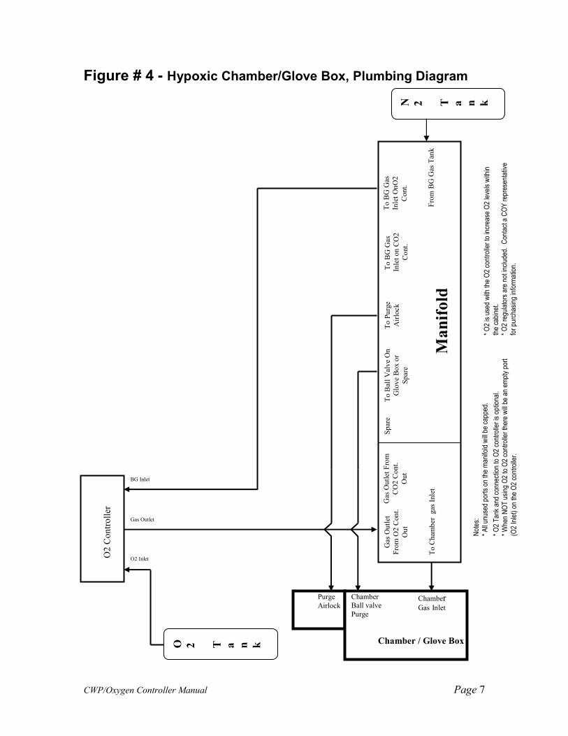
6. Determine the correct plumbing diagram below (figures 4 thru 10) for proper
plumbing of Chamber/Glove Box/Cabinets. Choose the diagram based on type (chamber/glove box or cabinet) and options (i.e. heated and/or CO2 controller). Be sure to read any and all notes.
• Measure and cut a piece of tubing to reach between desired connections. Place a female fitting on each end of tubing. Using figure # 3 place 2 ty-wraps around the hose barb on the female fittings and pull them as tight as possible. Cut off excess ty-wrap. .
***WHEN CUTTING TUBING, THE ENDS SHOULD BE AS SQUARE AS POSSIBLE***
Figure # 3 Tubing connection to Quick Disconnect Fitting
7. When fittings are seated correctly to mating ends, you will hear a “click”.
When Hyperoxic (above ambient O2) environment is required; switch connections between the N2 regulator and O2 regulator.
Flexible Tubing
CWP/Oxygen Controller Manual Page 7
Figure # 4 - Hypoxic Chamber/Glove Box, Plumbing Diagram
Gas Outlet From
CO2 Cont.
Out
Spare
To Ball Valve On
Glove Box or
Spare
To Purge
Airlock
To BG Gas
Inlet on CO2
Cont.
To BG Gas
Inlet OnO2
Cont.
To Chamber gas Inlet
From BG Gas Tank
Gas Outlet
From O2 Cont.
Out
Chamber / Glove Box
O2 Controller
O2 Inlet
BG Inlet
Gas Outlet
O 2
T a
n k
Chamber Gas Inlet
Purge
Airlock
Not
es:
* A
ll un
used
por
ts o
n th
e m
anifo
ld w
ill b
e ca
pped
.
* O
2 Tan
k an
d co
nnec
tion
to O
2 co
ntro
ller is
opt
iona
l. * W
hen
NO
T u
sing
O2
to O
2 co
ntro
ller th
ere
will b
e an
em
pty
port
(O2
Inle
t) o
n th
e O
2 co
ntro
ller.
Chamber
Ball valve
Purge
N 2
T a
n k
* O
2 is
use
d w
ith th
e O
2 co
ntro
ller to
incr
ease
O2
leve
ls w
ithin
the
cabi
net.
* O
2 re
gula
tors
are
not
incl
uded
. C
onta
ct a
CO
Y rep
rese
ntat
ive
for pu
rcha
sing
info
rmat
ion.
Manifold

CWP/Oxygen Controller Manual Page 8
Figure # 5 - Hypoxic Chamber/Glove Box with Heater, Plumbing
Diagram
Gas Outlet From
CO2 Cont.
Out
Spare
To Ball Valve On
Glove Box or
Spare
To Purge
Airlock
To BG Gas
Inlet on CO2
Cont.
To BG Gas
Inlet OnO2
Cont.
To Chamber gas Inlet
From BG Gas Tank
Gas Outlet
From O2 Cont.
Out
Chamber / Glove Box
N 2
T a
n k
O2 Controller
O2 Inlet
BG Inlet
Gas Outlet
O 2
T a
n k
Chamber Gas Inlet
Purge
Airlock
Not
es:
* A
ll un
used
por
ts o
n th
e m
anifo
ld w
ill b
e ca
pped
.
* O
2 Tan
k an
d co
nnec
tion
to O
2 co
ntro
ller is
opt
iona
l. * W
hen
NO
T u
sing
O2
to O
2 co
ntro
ller th
ere
will b
e an
em
pty
port
(O2
Inle
t) o
n th
e O
2 co
ntro
ller.
* O2
is u
sed
with
the
O2
cont
rolle
r to
incr
ease
O2
leve
ls w
ithin
th
e ca
bine
t.
* O
2 re
gula
tors
are
not
incl
uded
. C
onta
ct a
CO
Y rep
rese
ntat
ive
for pu
rcha
sing
info
rmat
ion.
Manifold
CWP/Oxygen Controller Manual Page 9
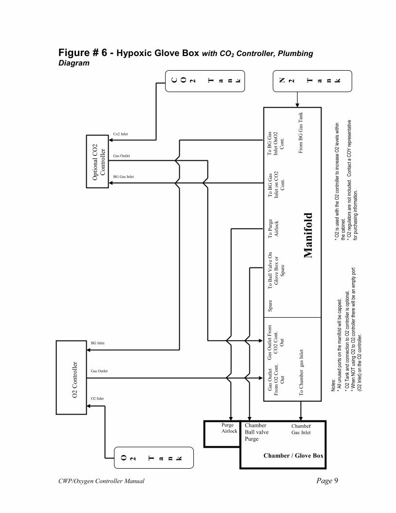
Figure # 6 - Hypoxic Glove Box with CO2 Controller, Plumbing
Diagram
Gas Outlet From
CO2 Cont.
Out
Spare
To Ball Valve On
Glove Box or
Spare
To Purge
Airlock
To BG Gas
Inlet on CO2
Cont.
To BG Gas
Inlet OnO2
Cont.
To Chamber gas Inlet
From BG Gas Tank
Gas Outlet
From O2 Cont.
Out
Chamber / Glove Box
Optional CO2
Controller
Co2 Inlet
Gas Outlet
BG Gas Inlet C O 2
T
a
n
k
N 2
T a
n k
O2 Controller
O2 Inlet
BG Inlet
Gas Outlet
O 2
T a
n k
Chamber Gas Inlet
Purge
Airlock Chamber
Ball valve
Purge
Not
es:
* A
ll un
used
por
ts o
n th
e m
anifo
ld w
ill b
e ca
pped
.
* O
2 Tan
k an
d co
nnec
tion
to O
2 co
ntro
ller is
opt
iona
l. * W
hen
NO
T u
sing
O2
to O
2 co
ntro
ller th
ere
will b
e an
em
pty
port
(O2
Inle
t) o
n th
e O
2 co
ntro
ller.
* O2
is u
sed
with
the
O2
cont
rolle
r to
incr
ease
O2
leve
ls w
ithin
th
e ca
bine
t.
* O
2 re
gula
tors
are
not
incl
uded
. C
onta
ct a
CO
Y rep
rese
ntat
ive
for pu
rcha
sing
info
rmat
ion.
Manifold
CWP/Oxygen Controller Manual Page 10
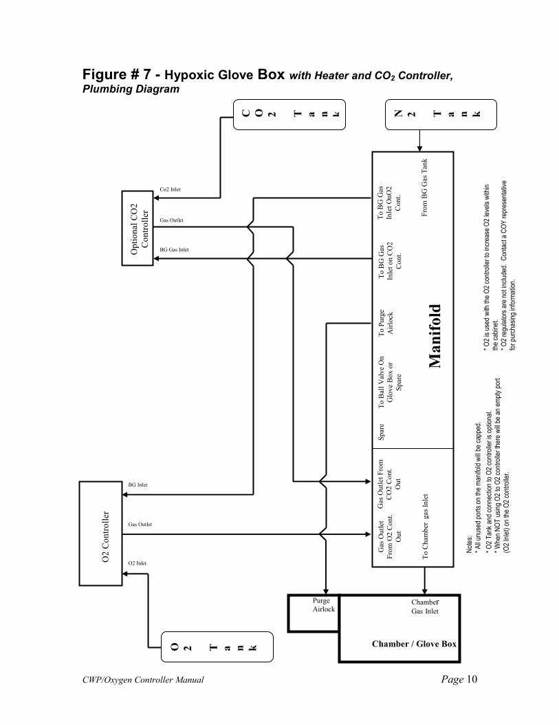
Figure # 7 - Hypoxic Glove Box with Heater and CO2 Controller,
Plumbing Diagram
Gas Outlet From
CO2 Cont.
Out
Spare
To Ball Valve On
Glove Box or
Spare
To Purge
Airlock
To BG Gas
Inlet on CO2
Cont.
To BG Gas
Inlet OnO2
Cont.
To Chamber gas Inlet
From BG Gas Tank
Gas Outlet
From O2 Cont.
Out
Chamber / Glove Box
Optional CO2
Controller
Co2 Inlet
Gas Outlet
BG Gas Inlet C O 2
T
a
n
k
N 2
T a
n k
O2 Controller
O2 Inlet
BG Inlet
Gas Outlet
O 2
T a
n k
Chamber Gas Inlet
Purge
Airlock
Not
es:
* A
ll un
used
por
ts o
n th
e m
anifo
ld w
ill b
e ca
pped
.
* O
2 Tan
k an
d co
nnec
tion
to O
2 co
ntro
ller is
opt
iona
l. * W
hen
NO
T u
sing
O2
to O
2 co
ntro
ller th
ere
will b
e an
em
pty
port
(O2
Inle
t) o
n th
e O
2 co
ntro
ller.
* O
2 is
use
d w
ith th
e O
2 co
ntro
ller to
incr
ease
O2
leve
ls w
ithin
th
e ca
bine
t.
* O
2 re
gula
tors
are
not
incl
uded
. C
onta
ct a
CO
Y rep
rese
ntat
ive
for pu
rcha
sing
info
rmat
ion.
Manifold

CWP/Oxygen Controller Manual Page 11
Figure # 8
Set up for In-Vitro O2 Control Cabinet for Hypoxia or Hyperoxia
Notes: CO2 Environment * To create an environment with CO2, a background gas mix with CO2 is required. Refer to the chart in the Gas Supply Setup section for more information.
O2 Controller * O2 Tank and connection to O2 controller is optional. * When NOT using O2 to O2 controller there will be an empty port (O2 Inlet) on the O2 controller. * O2 is used with the O2 controller to increase O2 within the cabinet. * O2 regulators are not included. Contact a COY representative for purchasing information.
O2 Controller
O2 Tank
O2 Control Cabinet
N2/CO2 Tank
Cabinet
Gas Inlet
BG Inlet
Gas O
utlet
O2 Inlet

CWP/Oxygen Controller Manual Page 12
Figure # 9
Set up for In-Vitro Hypoxic (Cabinet) Cell Culture with Optional CO2 Controller
Notes: CO2 Controller * Background Gas connected to CO2 controller is optional. * When NOT using BG gas to CO2controller there will be an empty port (BG Inlet) on the CO2 controller. * Background Gas is used with the CO2 controller to reduce CO2 within the cabinet. O2 Controller * O2 Tank and connection to O2 controller is optional. * When NOT using O2 to O2 controller there will be an empty port (O2 Inlet) on the O2 controller.
* O2 is used with the O2 controller to increase O2 within the cabinet. * O2 regulators are not included. Contact a COY representative for purchasing information.
O2 Controller
O2 Tank
O2 Control Cabinet
N2 Tank
Cabinet
Gas Inlet
BG Inlet
Gas O
utlet
O2 Inlet
CO2 Controller
BG Inlet
Gas O
utlet
CO2 Inlet
CO2 Tank

CWP/Oxygen Controller Manual Page 13
Figure # 10
Set up for In-Vivo O2 Control Cabinet for hypoxic or hyperoxic
Notes:
* No special notes included.
O2 Controller
O2 Tank
O2 Control Cabinet
N2 Tank
Cabinet
Gas Inlet
BG Inlet
Gas O
utlet
O2 Inlet

CWP/Oxygen Controller Manual Page 14
Gas Supply Setup
Passive CO2 Control If optional CO2 Control System has been purchased skip this section of the manual. To maintain the 5% CO2 level required for certain buffers to function properly, use the following table (figure 11) to spike each one of the gases going into the Oxygen Controller with the appropriate level of CO2 based on desired O2 levels.
Figure # 11
Desired Concentration of Oxygen
Air Displace to %
%CO2 Mix
required
Desired % CO2
%CO2 Concentration
in N2
20.80 100.00 0.00 5.00 N/A
15.00 72.12 27.88 5.00 17.9310
10.00 48.08 51.92 5.00 9.6296
5.00 24.04 75.96 5.00 6.5823
2.00 9.62 90.38 5.00 5.5319
1.00 4.81 95.19 5.00 5.2525
0.50 2.40 97.60 5.00 5.1232
0.10 0.48 99.52 5.00 5.0242

CWP/Oxygen Controller Manual Page 15
System Function
The Oxygen Controller is intended to maintain an oxygen level in a Chamber/Glove Box/Cabinet by sensing the current concentration, and then opening the appropriate solenoid valve to allow gas to flow and purge the system. The Oxygen set point is used to set the oxygen range desired in the chamber. The Controller has been programmed to maintain an oxygen set point of +/- 0.2 %, this is the Control Tolerance. Under normal use, only one gas line will be open at a time. The gas flow must be adjusted using the Flow Meters on the front of the Controller. The gas flow on the Flow Meters can only be adjusted while gas is flowing through that particular Valve. To adjust the Flow Meters, simply turn the black Knob on the front of the Flow Meter. Clockwise restrict flow, counter clockwise increases flow. Reference figure # 12 for O2 Controller gas flow settings. UNDER NO CIRCUMSTANCE SHOULD THE INLET PRESSURE EXCEED 10 PSI. GAS PRESSURES IN EXCESS OF 10 PSI MAY DAMAGE THE O2 CONTROLLER AND VOID THE WARRANTY. To obtain uniform O2 concentration throughout the Chamber/Glove Box/Cabinet, the small circulating fan must be on at ALL times. Please note that in Chamber/Glove Box the addition of a COY Fan Box (heated or unheated) may eliminate the need for this fan, depending upon the size of the chamber.
The alarm (AL) and temperature (C°/F°) functions are not included with O2 Controller; therefore, these indicator lights will not work. During operation, the Chamber/Glove Box will pressurize so that the sleeves may begin to stand out. This excess pressure will be removed by the COY Automatic pressure relief valves installed on the COY Chamber/Glove Boxes. Be sure that these pressure relief valves are not blocked.

CWP/Oxygen Controller Manual Page 16
Below are recommended Flow Rates
FIGURE # 12
Type/Size Flow Rate (SCFH)
Flow Rate (SCFH)
Polymer and Aluminum, Chamber / Glove Box
O2 Gas* Background
Gas Mini Polymer ≤ 2 ≤ 10 1 Person Polymer/Aluminum ≤ 2 ≤ 10 2 Person Polymer ≤ 4 ≤ 20 2 Person Aluminum ≤ 6 ≤ 30 Flexible Vinyl Units One Person ≤ 8 ≤ 50 Two Person ≤ 10 ≤ 60 Mini ≤ 4 ≤ 40 In-Vitro Cabinets Model 1 < 0.2 ≤ 1 Model 2 < 0.2 ≤ 1.5 Model 3 ≤ 0.2 ≤ 2.5 Model 4 ≤ 0.4 ≤ 4 In-Vivo Cabinets Model 15 ≤ 1 ≤ 6 Model 30 ≤ 2 ≤ 10 Model 60 ≤ 4 ≤ 20
*NOTE: The O2 Flow Rates assume a 100% tank of O2 is used. For forced air or other % of O2 rates will have to be increased.

CWP/Oxygen Controller Manual Page 17
Operation/set point of O2 Controller 1. Plug the Controller into an electrical outlet. 2. Turn the unit on using the rocker switch on the back. 3. After going through a self test routine, the display will show a red and green
number. The red number indicates Present Value (PV) and the measured O2 concentration and the green number is the Oxygen Set Point Value (SV).
4. Use Figure # 13 to adjust the set point. Press the ▲▼ keys to adjust the SV
(green numbers displayed) to desired O2 setting.
Figure # 13 - O2 Controller Display
Top Red Number – PV (present value)
Bottom Green Number – SV (set-point value)
Red Number on Side – Indicate gas output ON
1 = O2 Gas / 2 = Background Gas
▲▼ Keys – Adjust SV up or down
� Key – Not Used
∞ Key – Not Used
EZ Key – Not Used
Yellow Zone Indicator – Not Used
5. Once SV display is adjusted to desired O2 setting the controller is ready to
start controlling O2 in the Chamber/Glove Box/Cabinet.

CWP/Oxygen Controller Manual Page 18
Calibration of the O2 Controller If the High accuracy kit was purchased please follow Calibration instructions for High Accuracy manual. If you cannot find the High Accuracy calibrations manual please contact [email protected]
Do Not Place O2 sensor straight up. It needs to be in the horizontal position or facing straight down. The sensor has an expected life of greater than 2 years. During that time, there may be a downward drift in the O2 measurements. It is best to periodically check the calibration.
To do this:
1. Remove the sensor from the Chamber. 2. Plug the opening with the sensor fitting to maintain chamber
integrity. 3. Allow the sensor to equilibrate to ambient conditions for at
least 30 minutes. 4. The ambient oxygen concentration should read 20.9% +/- 1%. 5. If it does not, adjust the percent potentiometer (labeled %) on the
front of the O2 Controller until 20.9% +/-1% is read. To test for zero:
1. Place the sensor in a 100% nitrogen atmosphere. 2. Allow it to equilibrate for 30 minutes. 3. The Controller display should read 0%. 4. If it does not, adjust the zero potentiometer (labeled Zero) on the
front panel to 0%. Contact Coy Laboratory Products, Inc. if the sensor requires frequent recalibration at 734-475-2200 or email [email protected].