Embed Size (px)
Citation preview
Design of Catalytic Membrane Reactor for Oxidative
Coupling of Methane
F. Gallucci
M. van Sint Annaland
Chemical Process Intensification – Department of Chemical
Engineering and Chemistry - TU/e – The Netherlands
Process Intensification PIN-NL, April 10, 2013
1/ 36
Outline
• Introduction
• Design of catalytic membrane reactor
o Packed bed membrane reactor
o Hollow fiber catalytic membrane reactor
• Results
• Conclusions
2/ 36
Motivation
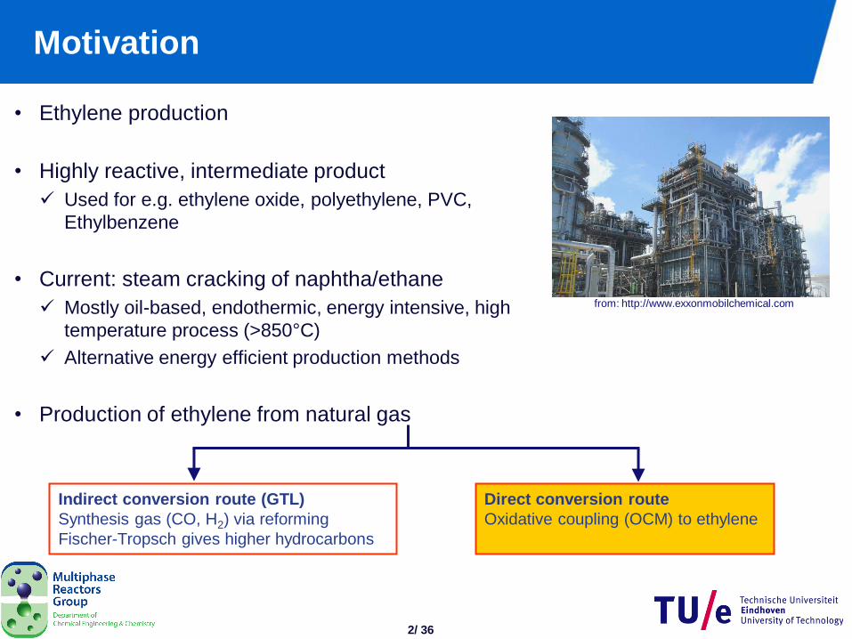
• Ethylene production
• Highly reactive, intermediate product
Used for e.g. ethylene oxide, polyethylene, PVC,
Ethylbenzene
• Current: steam cracking of naphtha/ethane
Mostly oil-based, endothermic, energy intensive, high
temperature process (>850°C)
Alternative energy efficient production methods
• Production of ethylene from natural gas
Indirect conversion route (GTL)
Synthesis gas (CO, H2) via reforming
Fischer-Tropsch gives higher hydrocarbons
Direct conversion route
Oxidative coupling (OCM) to ethylene
from: http://www.exxonmobilchemical.com
3/ 36
Introduction
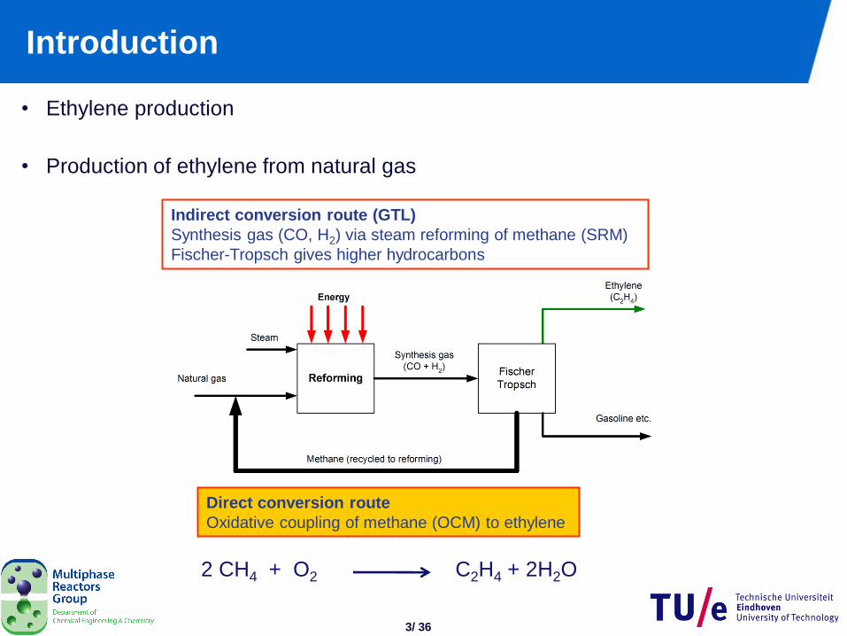
• Ethylene production
• Production of ethylene from natural gas
Indirect conversion route (GTL)
Synthesis gas (CO, H2) via steam reforming of methane (SRM)
Fischer-Tropsch gives higher hydrocarbons
Direct conversion route
Oxidative coupling of methane (OCM) to ethylene
2 CH4 + O2 C2H4 + 2H2O
4/ 36
Introduction contd…
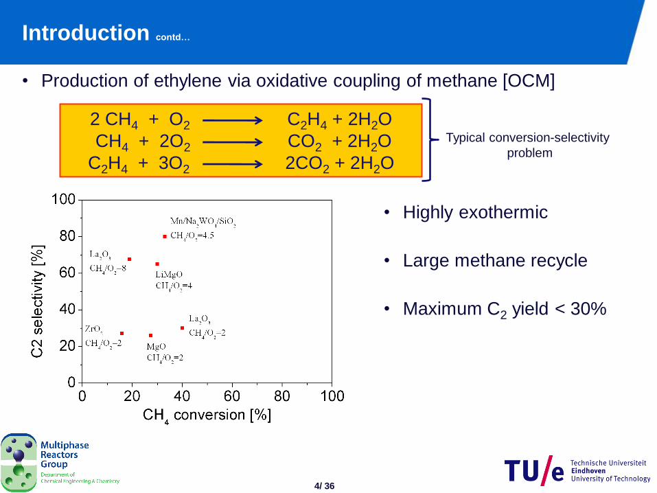
• Production of ethylene via oxidative coupling of methane [OCM]
2 CH4 + O2 C2H4 + 2H2O
CH4 + 2O2 CO2 + 2H2O
C2H4 + 3O2 2CO2 + 2H2O
Typical conversion-selectivity
problem
• Highly exothermic
• Large methane recycle
• Maximum C2 yield < 30%
5/ 36
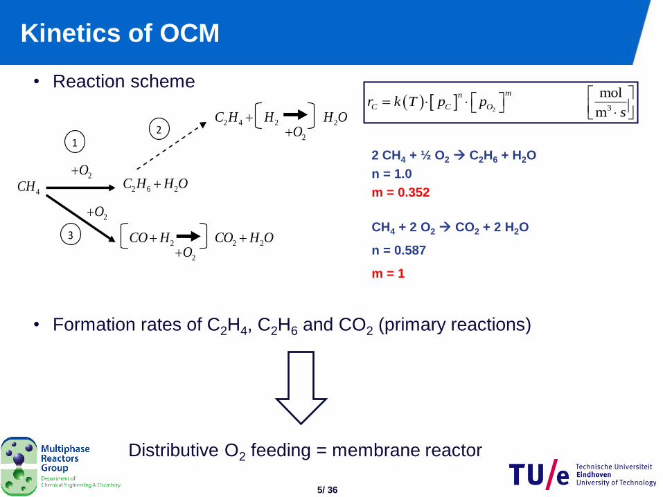
Kinetics of OCM
• Reaction scheme
• Formation rates of C2H4, C2H6 and CO2 (primary reactions)
2O
2O2 2CO H O
2O2H
1 2
3
2 6 2C H H O4CH
2CO H
2O
2 4 C H 2H O
2 3
mol
m
mn
C C Or k T p ps
2 CH4 + ½ O2 C2H6 + H2O
n = 1.0
m = 0.352
CH4 + 2 O2 CO2 + 2 H2O
n = 0.587
m = 1
Distributive O2 feeding = membrane reactor
6/ 36
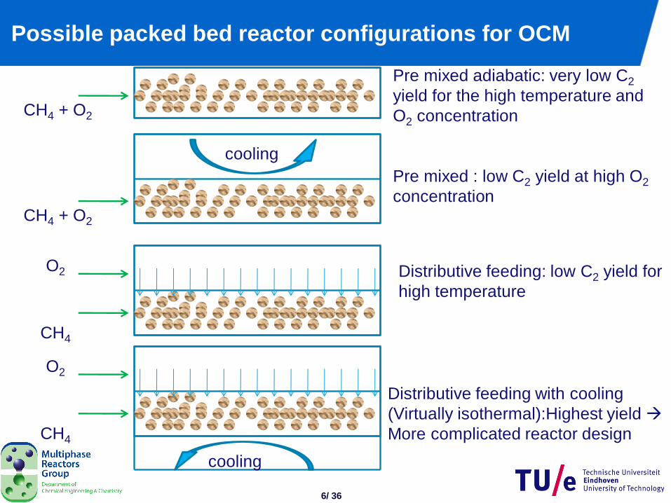
Possible packed bed reactor configurations for OCM
CH4 + O2
cooling
CH4 + O2
CH4
O2
Pre mixed adiabatic: very low C2
yield for the high temperature and
O2 concentration
Pre mixed : low C2 yield at high O2
concentration
Distributive feeding: low C2 yield for
high temperature
CH4
O2
cooling
Distributive feeding with cooling
(Virtually isothermal):Highest yield
More complicated reactor design
7/ 36
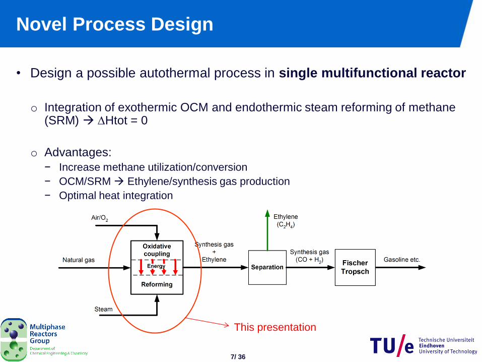
Novel Process Design
• Design a possible autothermal process in single multifunctional reactor
o Integration of exothermic OCM and endothermic steam reforming of methane (SRM) Htot = 0
o Advantages:
− Increase methane utilization/conversion
− OCM/SRM Ethylene/synthesis gas production
− Optimal heat integration
This presentation
8/ 36
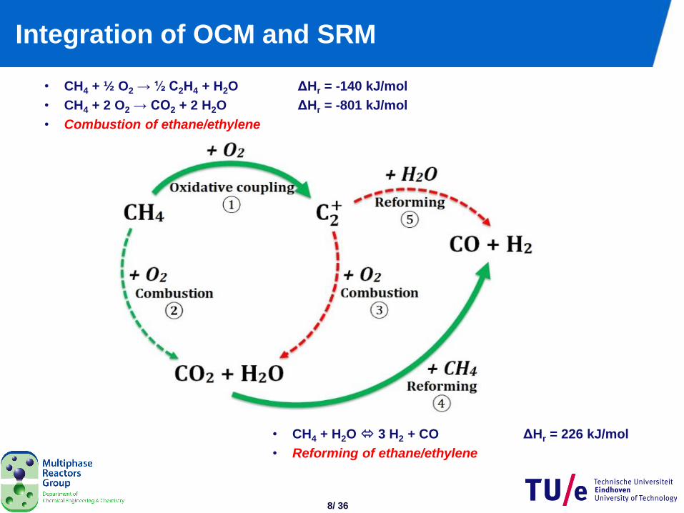
Integration of OCM and SRM
• CH4 + ½ O2 → ½ C2H4 + H2O ΔHr = -140 kJ/mol
• CH4 + 2 O2 → CO2 + 2 H2O ΔHr = -801 kJ/mol
• Combustion of ethane/ethylene
• CH4 + H2O 3 H2 + CO ΔHr = 226 kJ/mol
• Reforming of ethane/ethylene
9/ 36
Outline
• Introduction
• Design of catalytic membrane reactor
o Packed bed membrane reactor
o Hollow fiber catalytic membrane reactor
• Results
• Conclusions
10/ 36
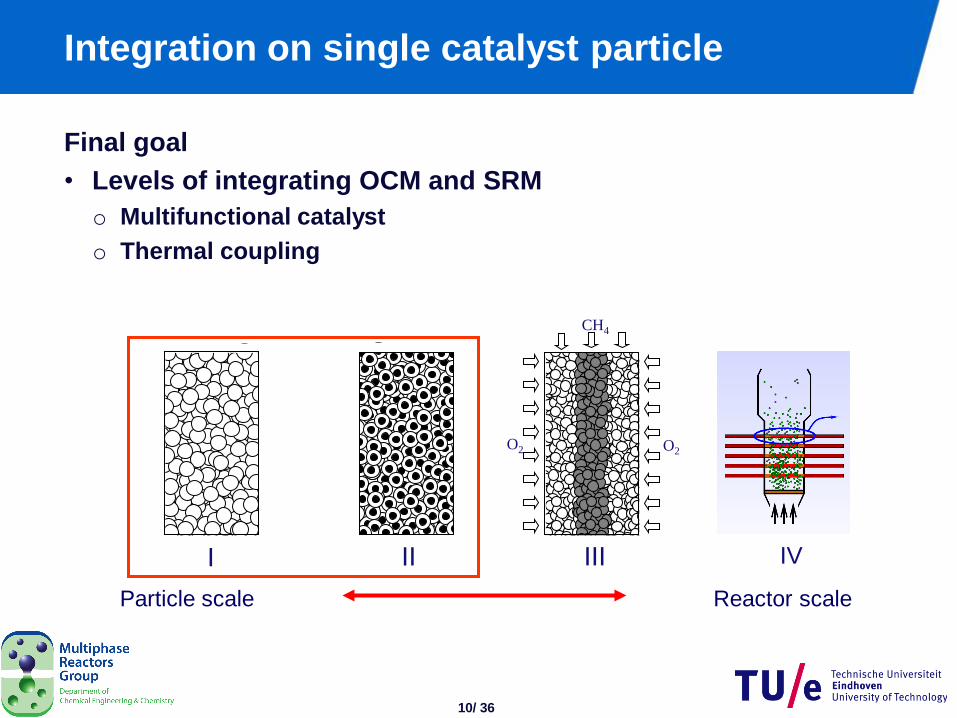
Integration on single catalyst particle
Final goal
• Levels of integrating OCM and SRM
o Multifunctional catalyst
o Thermal coupling
Particle scale Reactor scale
O2 O2
CH4
I II III IV
11/ 36
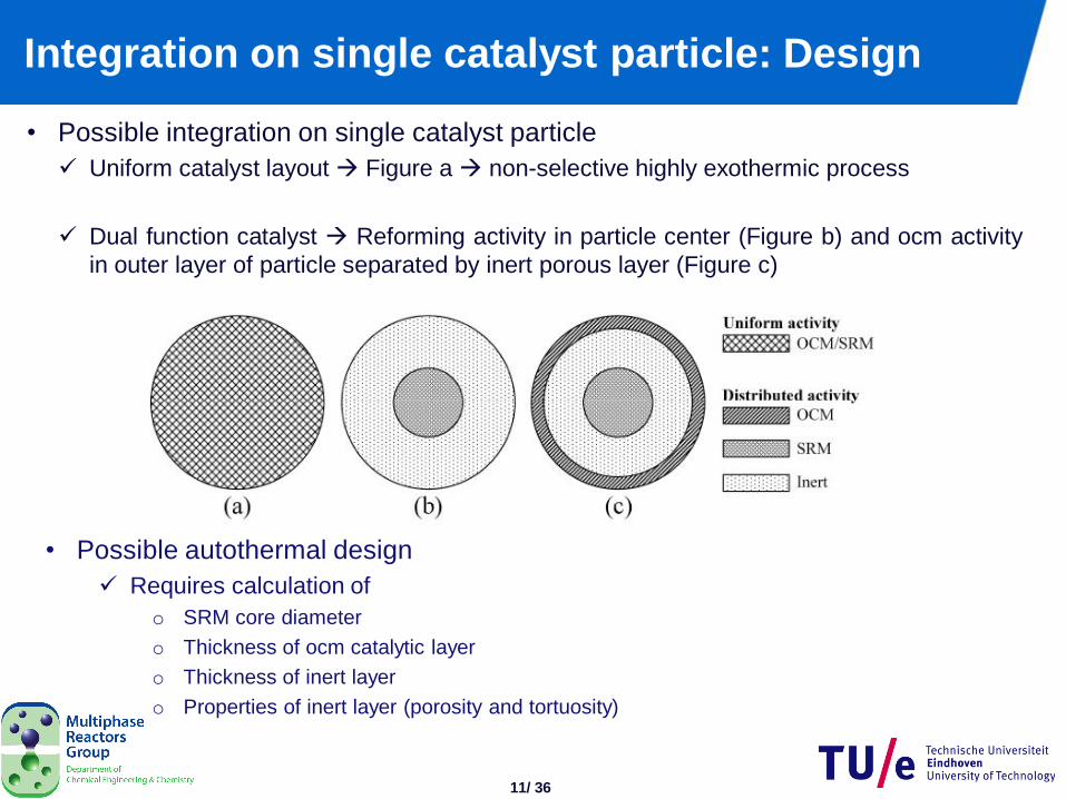
Integration on single catalyst particle: Design
• Possible integration on single catalyst particle
Uniform catalyst layout Figure a non-selective highly exothermic process
Dual function catalyst Reforming activity in particle center (Figure b) and ocm activity
in outer layer of particle separated by inert porous layer (Figure c)
• Possible autothermal design
Requires calculation of
o SRM core diameter
o Thickness of ocm catalytic layer
o Thickness of inert layer
o Properties of inert layer (porosity and tortuosity)
12/ 36
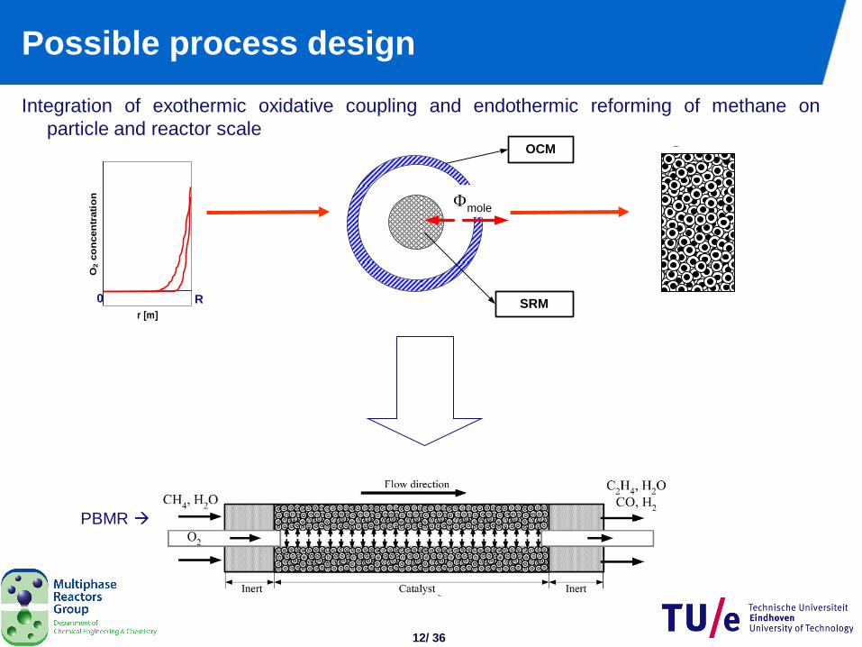
Possible process design
Integration of exothermic oxidative coupling and endothermic reforming of methane on
particle and reactor scale OCM
SRM
mole
r [m]
O2 c
on
cen
trati
on
0 R
PBMR
13/ 36
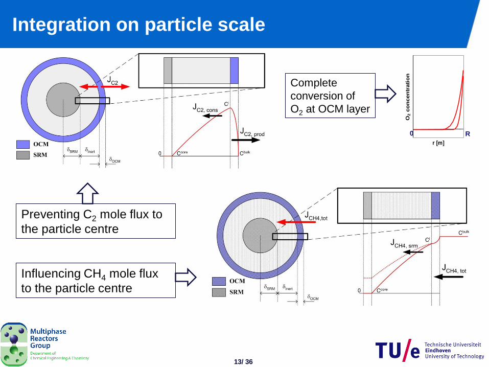
Integration on particle scale
Influencing CH4 mole flux
to the particle centre
Preventing C2 mole flux to
the particle centre
r [m]
O2 c
on
cen
trati
on
0 R
Complete
conversion of
O2 at OCM layer
14/ 36
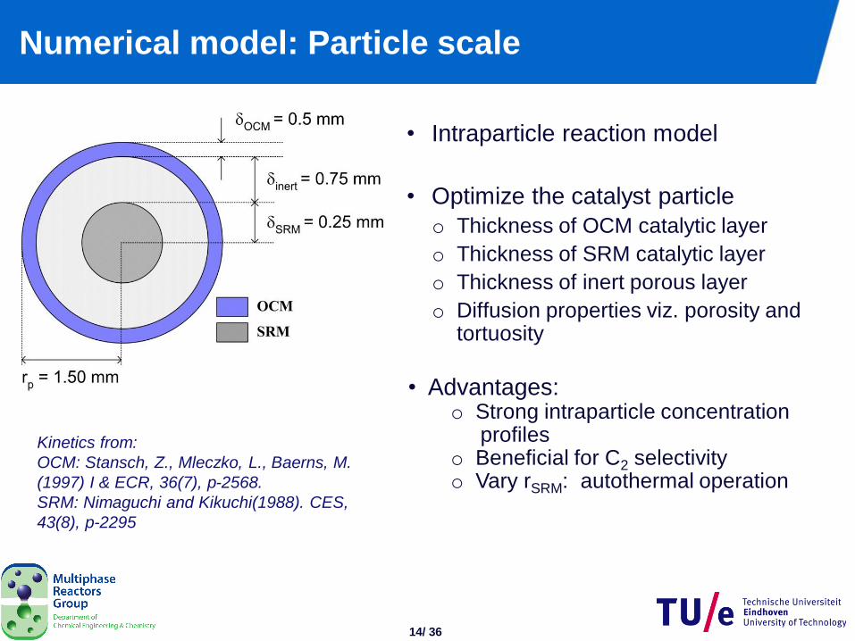
Numerical model: Particle scale
Kinetics from:
OCM: Stansch, Z., Mleczko, L., Baerns, M.
(1997) I & ECR, 36(7), p-2568.
SRM: Nimaguchi and Kikuchi(1988). CES,
43(8), p-2295
• Intraparticle reaction model
• Optimize the catalyst particle
o Thickness of OCM catalytic layer
o Thickness of SRM catalytic layer
o Thickness of inert porous layer
o Diffusion properties viz. porosity and tortuosity
• Advantages: o Strong intraparticle concentration profiles o Beneficial for C2 selectivity o Vary rSRM: autothermal operation
15/ 36
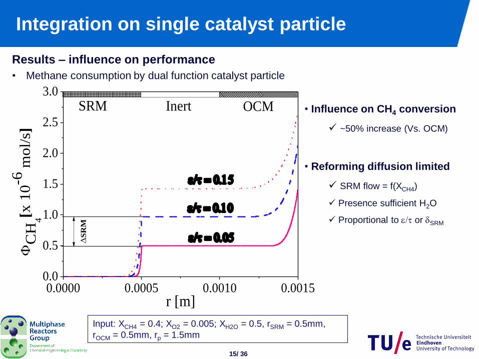
Integration on single catalyst particle
Results – influence on performance
• Methane consumption by dual function catalyst particle
• Influence on CH4 conversion
~50% increase (Vs. OCM)
• Reforming diffusion limited
SRM flow = f(XCH4)
Presence sufficient H2O
Proportional to e/t or dSRM
Input: XCH4 = 0.4; XO2 = 0.005; XH2O = 0.5, rSRM = 0.5mm,
rOCM = 0.5mm, rp = 1.5mm
0.0000 0.0005 0.0010 0.00150.0
0.5
1.0
1.5
2.0
2.5
3.0
InertSRM
e/t
e/t
C
H4
[x 1
0-6
mol/
s]
r [m]
e/t
OCM
S
RM
16/ 36
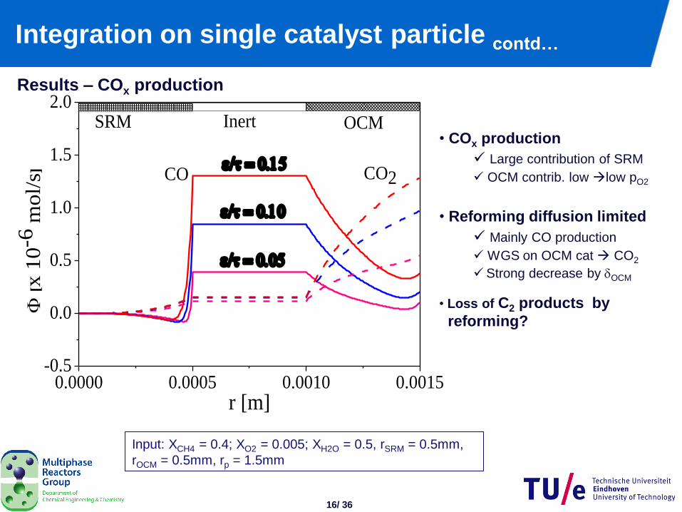
Integration on single catalyst particle contd…
Results – COx production
• COx production
Large contribution of SRM
OCM contrib. low low pO2
• Reforming diffusion limited
Mainly CO production
WGS on OCM cat CO2
Strong decrease by dOCM
• Loss of C2 products by
reforming?
Input: XCH4 = 0.4; XO2 = 0.005; XH2O = 0.5, rSRM = 0.5mm,
rOCM = 0.5mm, rp = 1.5mm
0.0000 0.0005 0.0010 0.0015-0.5
0.0
0.5
1.0
1.5
2.0
CO2
[x 1
0-6
mol/
s]
r [m]
InertSRM OCM
CO
e/t
e/t
e/t
17/ 36
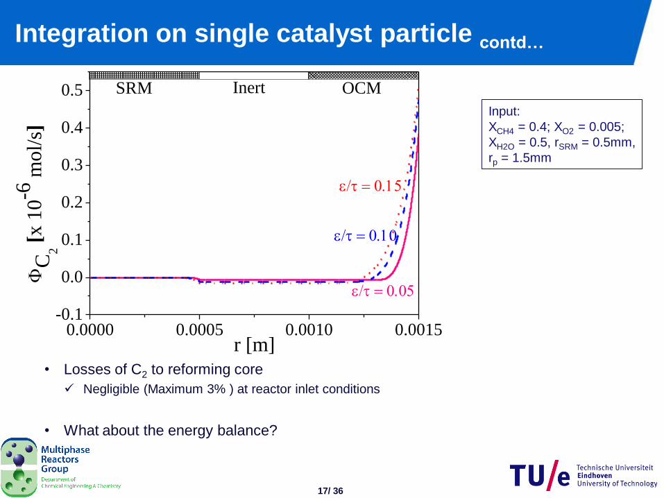
Integration on single catalyst particle contd…
• Losses of C2 to reforming core
Negligible (Maximum 3% ) at reactor inlet conditions
• What about the energy balance?
Input:
XCH4 = 0.4; XO2 = 0.005;
XH2O = 0.5, rSRM = 0.5mm,
rp = 1.5mm
0.0000 0.0005 0.0010 0.0015-0.1
0.0
0.1
0.2
0.3
0.4
0.5 InertSRM
e/t
e/t
C
2 [x
10-6
mol/
s]
r [m]
e/t
OCM
18/ 36
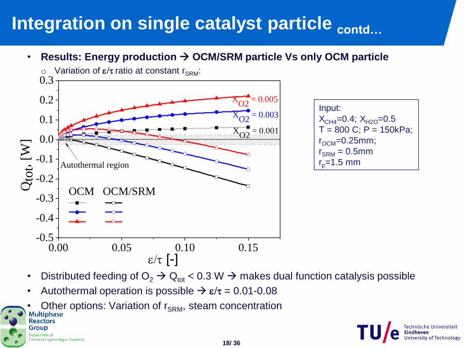
Integration on single catalyst particle contd…
• Results: Energy production OCM/SRM particle Vs only OCM particle
o Variation of e/tratio at constant rSRM:
• Distributed feeding of O2 Qtot < 0.3 W makes dual function catalysis possible
• Autothermal operation is possible e/t = 0.01-0.08
• Other options: Variation of rSRM, steam concentration
Input:
XCH4=0.4; XH2O=0.5
T = 800 C; P = 150kPa;
rOCM=0.25mm;
rSRM = 0.5mm
rp=1.5 mm
0.00 0.05 0.10 0.15-0.5
-0.4
-0.3
-0.2
-0.1
0.0
0.1
0.2
0.3
XO2
= 0.001
XO2
= 0.003
Qto
t, [
W]
e/t [-]
OCM OCM/SRM
XO2
= 0.005
Autothermal region
19/ 36
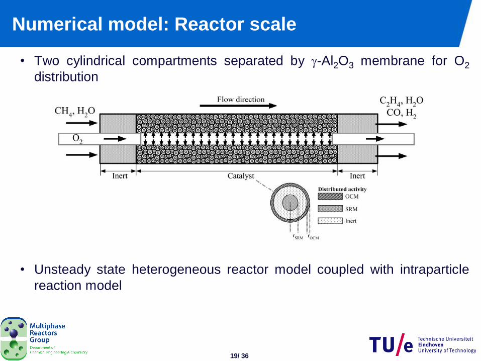
Numerical model: Reactor scale
• Two cylindrical compartments separated by -Al2O3 membrane for O2
distribution
• Unsteady state heterogeneous reactor model coupled with intraparticle
reaction model
20/ 36
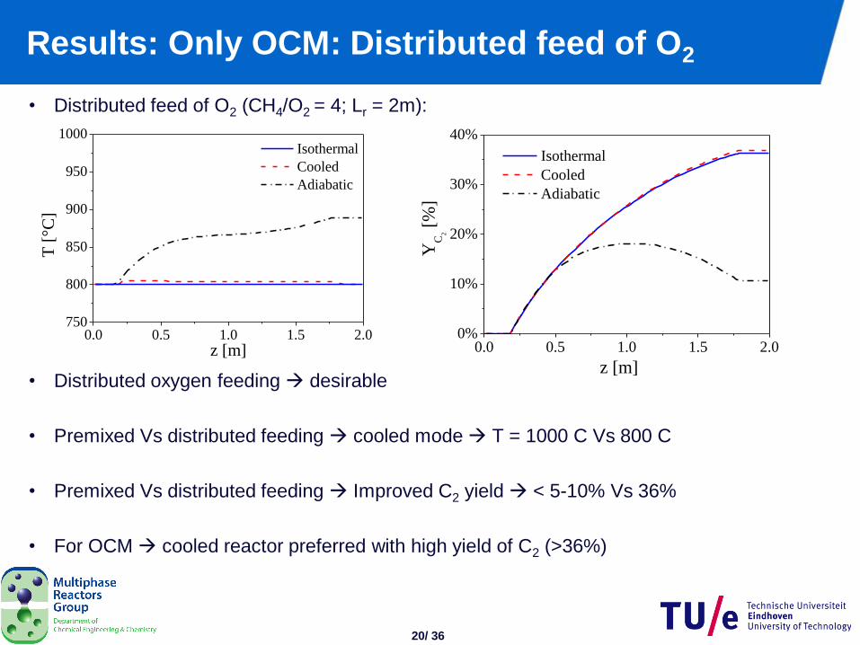
Results: Only OCM: Distributed feed of O2
• Distributed feed of O2 (CH4/O2 = 4; Lr = 2m):
• Distributed oxygen feeding desirable
• Premixed Vs distributed feeding cooled mode T = 1000 C Vs 800 C
• Premixed Vs distributed feeding Improved C2 yield < 5-10% Vs 36%
• For OCM cooled reactor preferred with high yield of C2 (>36%)
0.0 0.5 1.0 1.5 2.00%
10%
20%
30%
40%
YC
2
[%
]
z [m]
Isothermal
Cooled
Adiabatic
0.0 0.5 1.0 1.5 2.0750
800
850
900
950
1000
T [
°C]
z [m]
Isothermal
Cooled
Adiabatic
21/ 36 21
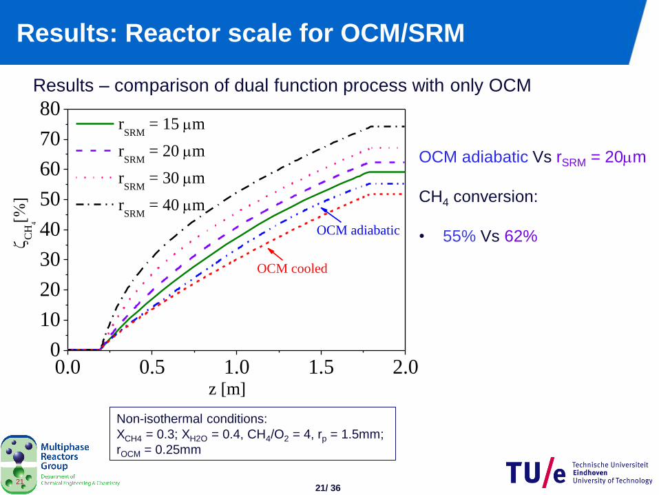
Results: Reactor scale for OCM/SRM
Results – comparison of dual function process with only OCM
Non-isothermal conditions:
XCH4 = 0.3; XH2O = 0.4, CH4/O2 = 4, rp = 1.5mm;
rOCM = 0.25mm
0.0 0.5 1.0 1.5 2.00
10
20
30
40
50
60
70
80
OCM adiabatic
C
H4
z [m]
rSRM
= 15 m
rSRM
= 20 m
rSRM
= 30 m
rSRM
= 40 m
OCM cooled
OCM adiabatic Vs rSRM = 20m
CH4 conversion:
• 55% Vs 62%
22/ 36 22
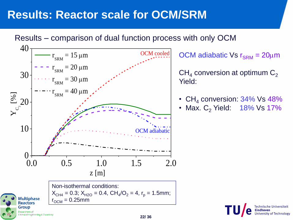
Results: Reactor scale for OCM/SRM
Results – comparison of dual function process with only OCM
Non-isothermal conditions:
XCH4 = 0.3; XH2O = 0.4, CH4/O2 = 4, rp = 1.5mm;
rOCM = 0.25mm
OCM adiabatic Vs rSRM = 20m
CH4 conversion at optimum C2
Yield:
• CH4 conversion: 34% Vs 48%
• Max. C2 Yield: 18% Vs 17%
0.0 0.5 1.0 1.5 2.00
10
20
30
40
OCM adiabatic
YC
2
[%
]
z [m]
rSRM
= 15 m
rSRM
= 20 m
rSRM
= 30 m
rSRM
= 40 m
OCM cooled
23/ 36
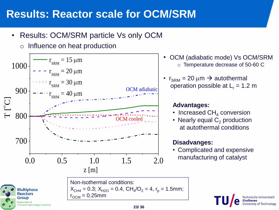
Results: Reactor scale for OCM/SRM
• Results: OCM/SRM particle Vs only OCM
o Influence on heat production
Non-isothermal conditions:
XCH4 = 0.3; XH2O = 0.4, CH4/O2 = 4, rp = 1.5mm;
rOCM = 0.25mm
• OCM (adiabatic mode) Vs OCM/SRM o Temperature decrease of 50-60 C
• rSRM = 20 m autothermal
operation possible at Lr = 1.2 m
Advantages:
• Increased CH4 conversion
• Nearly equal C2 production
at autothermal conditions
Disadvanges:
• Complicated and expensive
manufacturing of catalyst
0.0 0.5 1.0 1.5 2.0
700
800
900
1000
OCM adiabatic
T [C
]
z [m]
rSRM
= 15 m
rSRM
= 20 m
rSRM
= 30 m
rSRM
= 40 m
OCM cooled
24/ 36
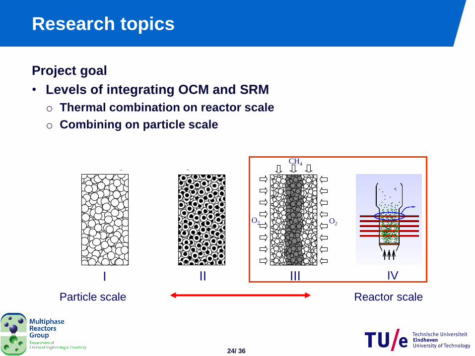
Research topics
Project goal
• Levels of integrating OCM and SRM
o Thermal combination on reactor scale
o Combining on particle scale
Particle scale Reactor scale
O2 O2
CH4
I II III IV
25/ 36
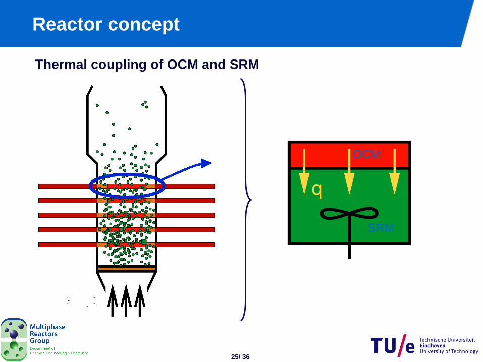
Reactor concept
Thermal coupling of OCM and SRM
SRM
OCM
26/ 36
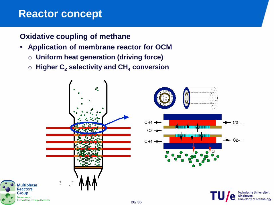
Reactor concept
Oxidative coupling of methane
• Application of membrane reactor for OCM
o Uniform heat generation (driving force)
o Higher C2 selectivity and CH4 conversion
27/ 36
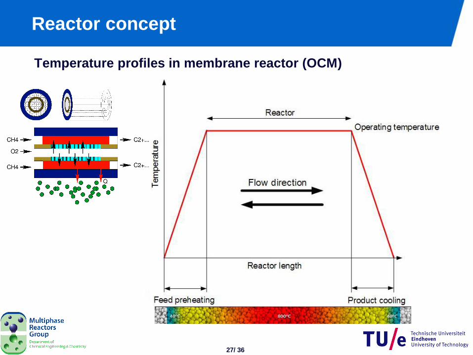
Reactor concept
Temperature profiles in membrane reactor (OCM)
28/ 36
Outline
• Introduction
• Design of catalytic membrane reactor
o Packed bed membrane reactor
o Hollow fiber catalytic membrane reactor
• Results
• Conclusions
29/ 36
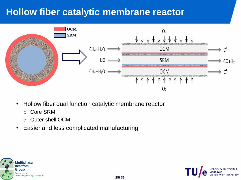
Hollow fiber catalytic membrane reactor
• Hollow fiber dual function catalytic membrane reactor
o Core SRM
o Outer shell OCM
• Easier and less complicated manufacturing
SRM
OCM
30/ 36
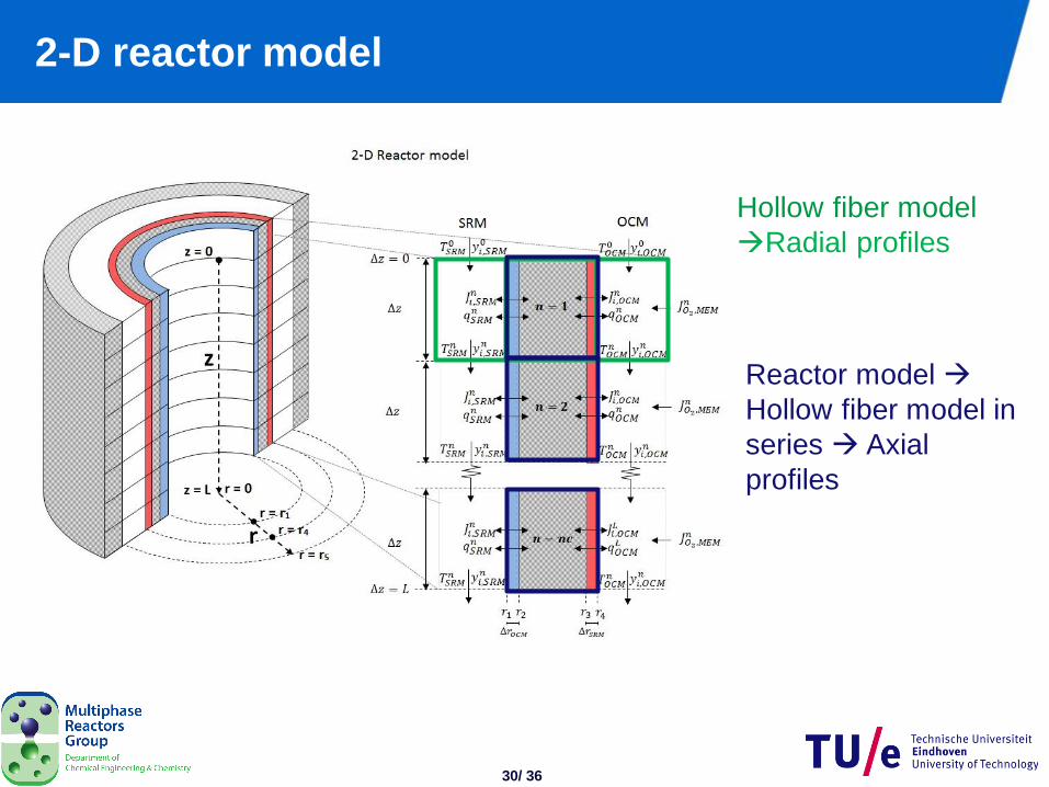
2-D reactor model
Hollow fiber model
Radial profiles
Reactor model
Hollow fiber model in
series Axial
profiles
31/ 36
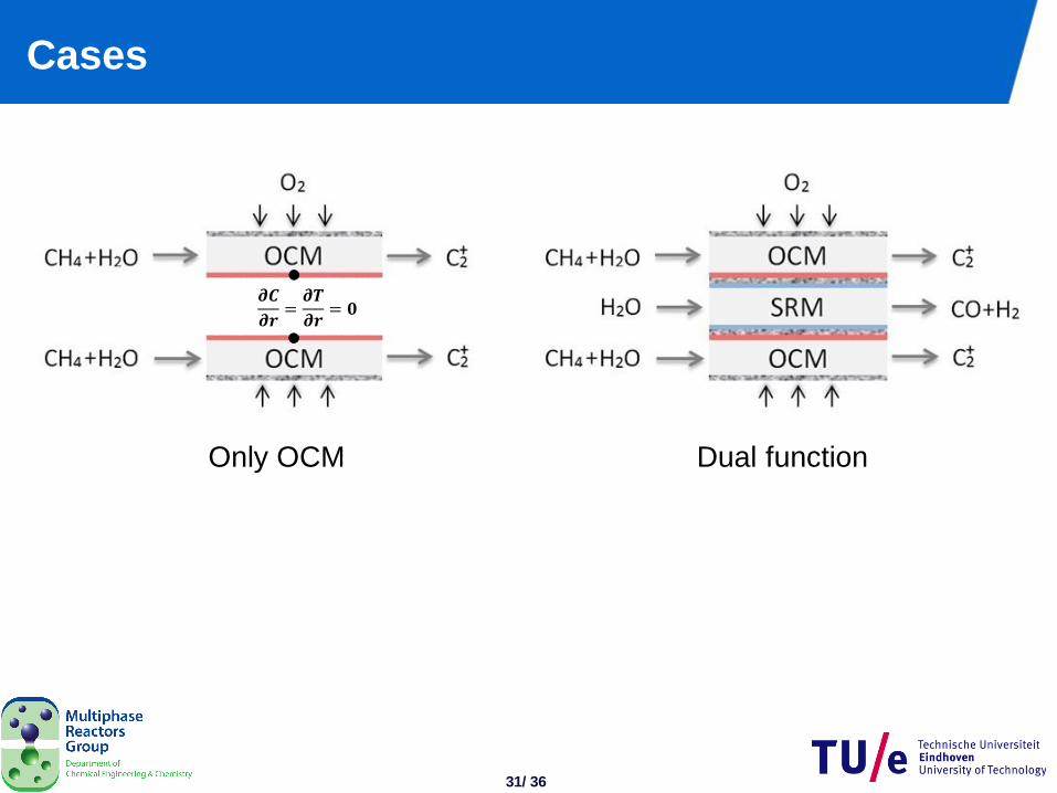
Cases
Only OCM Dual function
𝝏𝑪
𝝏𝒓=𝝏𝑻
𝝏𝒓= 𝟎
32/ 36
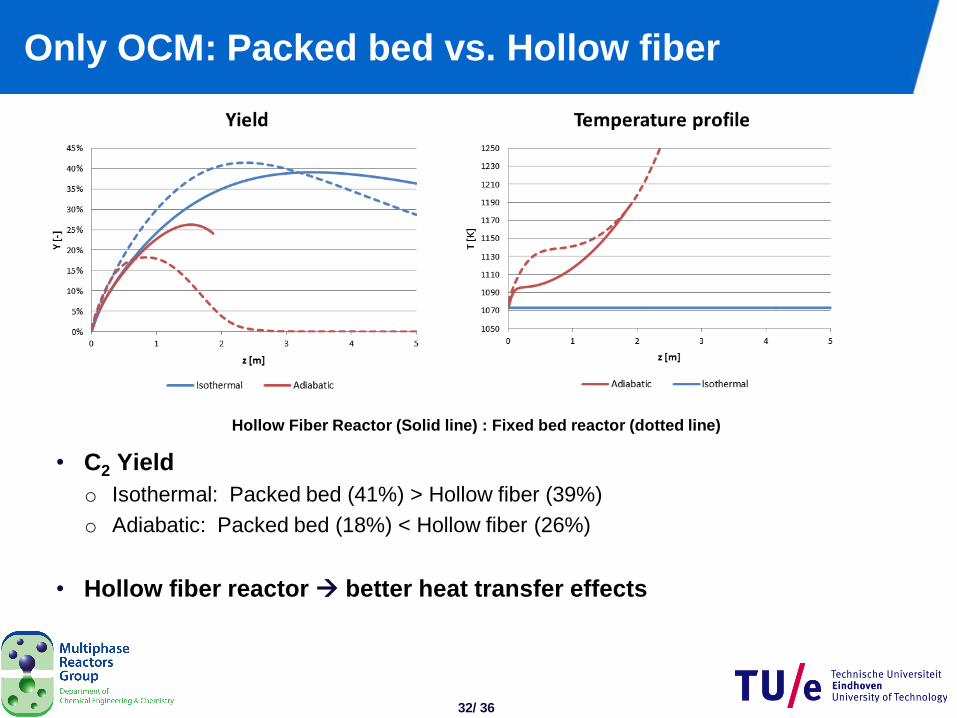
Only OCM: Packed bed vs. Hollow fiber
• C2 Yield
o Isothermal: Packed bed (41%) > Hollow fiber (39%)
o Adiabatic: Packed bed (18%) < Hollow fiber (26%)
• Hollow fiber reactor better heat transfer effects
Hollow Fiber Reactor (Solid line) : Fixed bed reactor (dotted line)
33/ 36
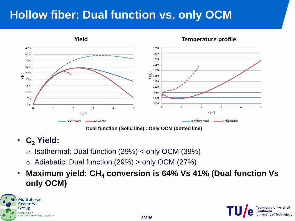
Hollow fiber: Dual function vs. only OCM
• C2 Yield:
o Isothermal: Dual function (29%) < only OCM (39%)
o Adiabatic: Dual function (29%) > only OCM (27%)
• Maximum yield: CH4 conversion is 64% Vs 41% (Dual function Vs
only OCM)
Dual function (Solid line) : Only OCM (dotted line)

34/ 36
Conclusions
• OCM / SRM integration in single multifunctional reactor
o Reactor performance:
Hollow fiber catalytic membrane reactor > Packed bed membrane reactor
o Increased CH4 conversion compared to only OCM
o Simultaneous production of C2 and syngas without heat exchange
equipment
• Autothermal operation possible in both reactors
• The models presented here could be useful to provide the guidelines
for designing and improving the overall performance of the process
• Outlook
Experimental demonstration
35/ 36
Acknowledgments
• Collaborations
Prof. dr. Ir. Leon Lefferts (University of Twente, Netherlands)
VITO (Belgium)
Tecnalia (Spain)
BIC (Russia)
Financial support from NWO/ASPECT


![Oxidative coupling of methane in a mixed-conducting ...Several perovskite-type oxides were already investigated as catalysts for the methane coupling reaction [ 10-15 ]. Some LaCoO3-based](https://img.pdfslide.us/doc/110x75/60ff1af5b62b793f9d3f14d4/oxidative-coupling-of-methane-in-a-mixed-conducting-several-perovskite-type.jpg)