Embed Size (px)
Citation preview
SHS ConnectorHarness Assembly Manual
SHS Assembly Manual 2010 Page 1
SHS Connector Assembly Instructions
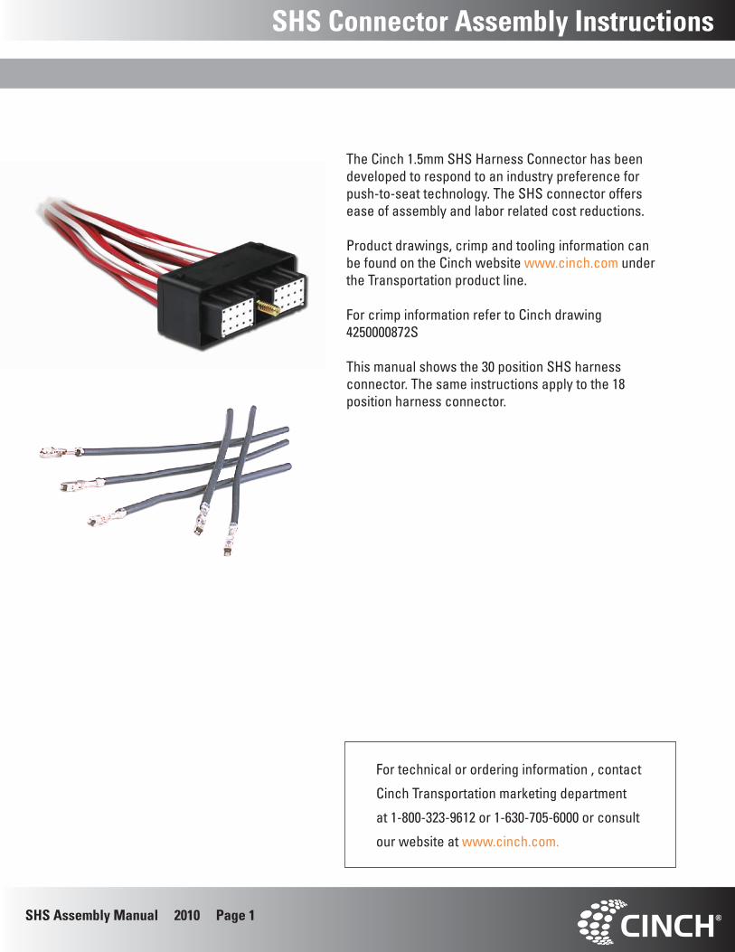
The Cinch 1.5mm SHS Harness Connector has been developed to respond to an industry preference for push-to-seat technology. The SHS connector offers ease of assembly and labor related cost reductions. Product drawings, crimp and tooling information can be found on the Cinch website www.cinch.com under the Transportation product line. For crimp information refer to Cinch drawing 4250000872S This manual shows the 30 position SHS harness connector. The same instructions apply to the 18 position harness connector.
For technical or ordering information , contact
Cinch Transportation marketing department
at 1-800-323-9612 or 1-630-705-6000 or consult
our website at www.cinch.com.
SHS Assembly Manual 2010 Page 2
Harness Assembly Instructions
Install seal plugs in unused cavities before loading the wires. Insert seal plugs in all unused cavities.
A connector without plugs in the unused cavities will not be sealed.
Connector Preparation
Push the plug all the way in.
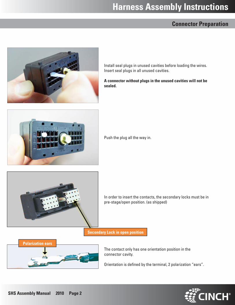
In order to insert the contacts, the secondary locks must be in pre-stage/open position. (as shipped)
The contact only has one orientation position in the connector cavity.
Orientation is defined by the terminal, 2 polarization “ears”.
Polarization ears
Secondary Lock in open position
SHS Assembly Manual 2010 Page 3
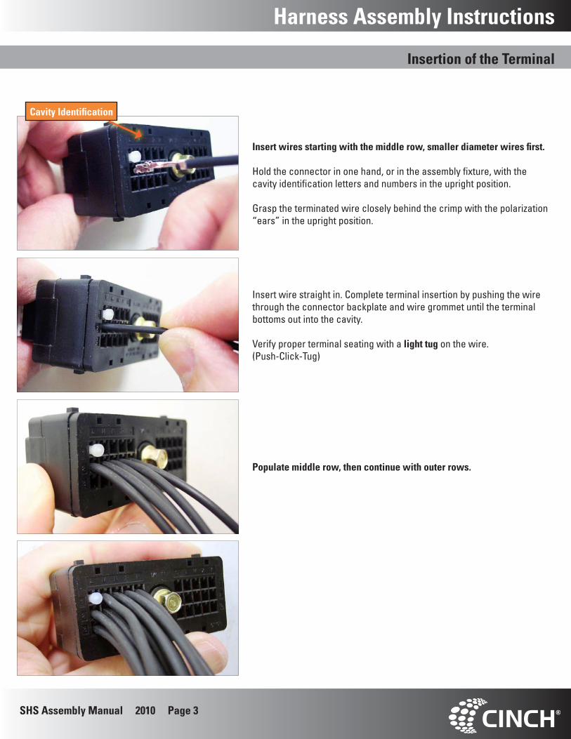
Populate middle row, then continue with outer rows.
Harness Assembly Instructions
Insert wires starting with the middle row, smaller diameter wires first.
Hold the connector in one hand, or in the assembly fixture, with the cavity identification letters and numbers in the upright position.
Grasp the terminated wire closely behind the crimp with the polarization “ears” in the upright position.
Insertion of the Terminal
Insert wire straight in. Complete terminal insertion by pushing the wire through the connector backplate and wire grommet until the terminal bottoms out into the cavity.
Verify proper terminal seating with a light tug on the wire.(Push-Click-Tug)
Cavity Identification
SHS Assembly Manual 2010 Page 4
Harness Assembly Instructions
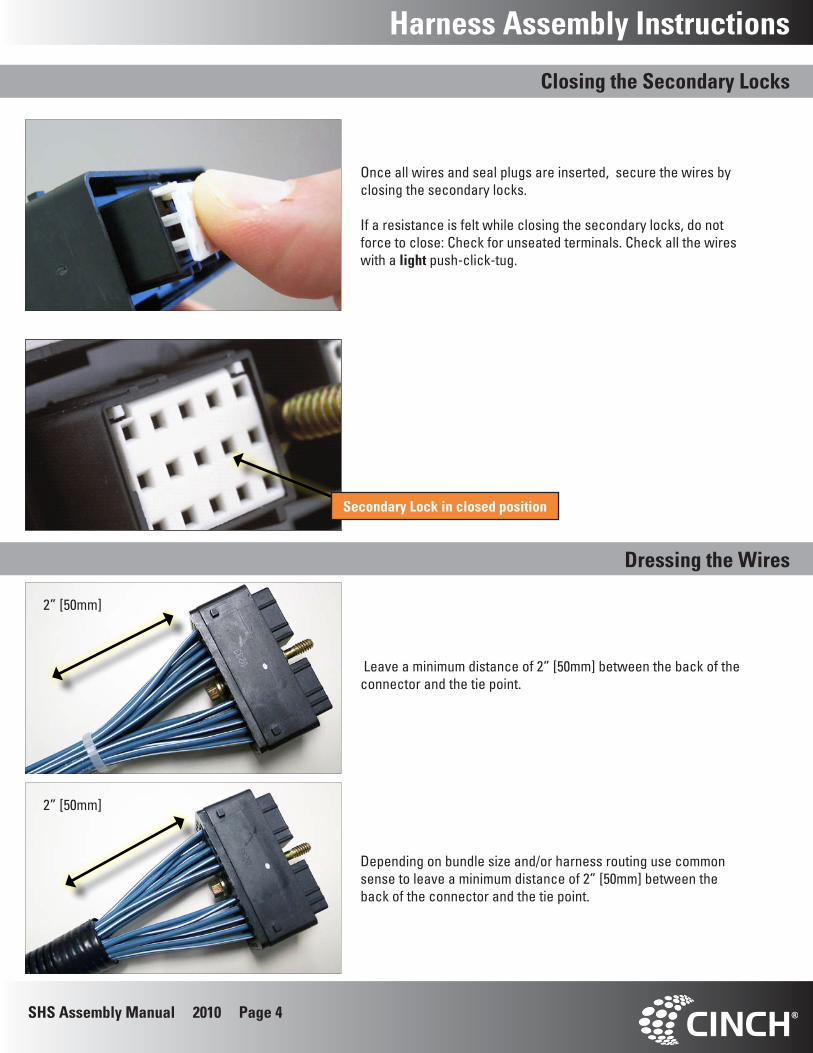
Once all wires and seal plugs are inserted, secure the wires by closing the secondary locks.
If a resistance is felt while closing the secondary locks, do not force to close: Check for unseated terminals. Check all the wires with a light push-click-tug.
Closing the Secondary Locks
Leave a minimum distance of 2” [50mm] between the back of the connector and the tie point.
Dressing the Wires
Secondary Lock in closed position
2” [50mm]
2” [50mm]
Depending on bundle size and/or harness routing use common sense to leave a minimum distance of 2” [50mm] between the back of the connector and the tie point.
SHS Assembly Manual 2010 Page 5
Terminal Removal Instructions
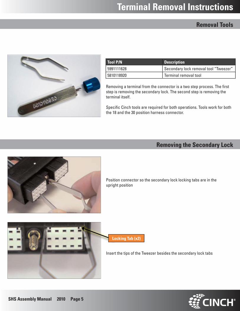
Tool P/N Description
5991111628 Secondary lock removal tool “Tweezer”5810118920 Terminal removal tool
Removing the Secondary Lock
Removing a terminal from the connector is a two step process. The first step is removing the secondary lock. The second step is removing the terminal itself.
Specific Cinch tools are required for both operations. Tools work for both the 18 and the 30 position harness connector.
Position connector so the secondary lock locking tabs are in the upright position
Insert the tips of the Tweezer besides the secondary lock tabs
Locking Tab (x2)
Removal Tools
SHS Assembly Manual 2010 Page 6
Terminal Removal Instructions
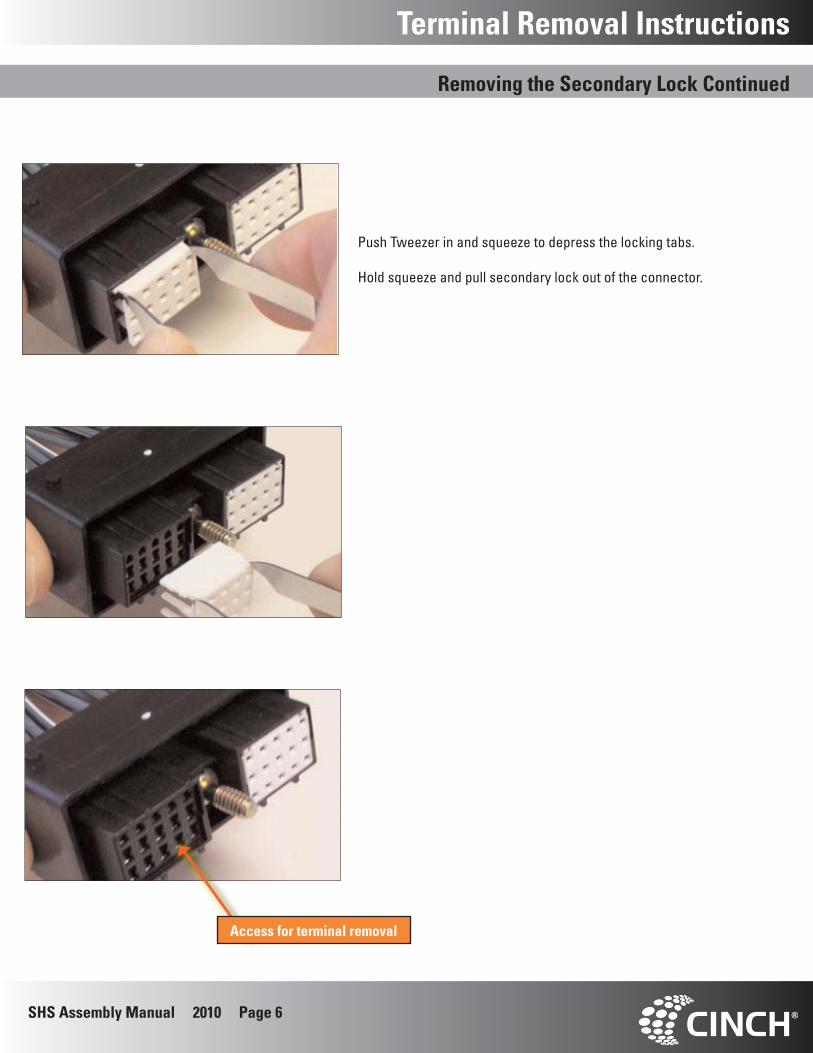
Push Tweezer in and squeeze to depress the locking tabs.
Hold squeeze and pull secondary lock out of the connector.
Access for terminal removal
Removing the Secondary Lock Continued
SHS Assembly Manual 2010 Page 7
Removing the Terminal
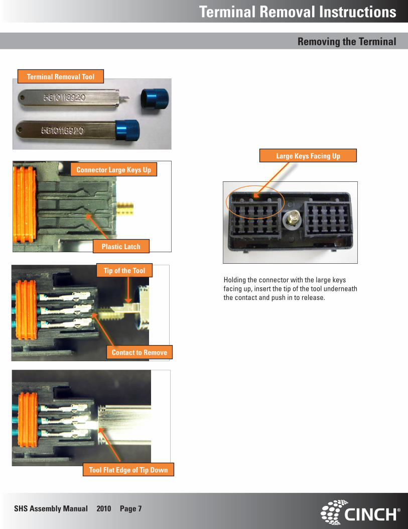
Tip of the Tool
Contact to Remove
Tool Flat Edge of Tip Down
Terminal Removal Instructions
Holding the connector with the large keys facing up, insert the tip of the tool underneath the contact and push in to release.
Terminal Removal Tool
Large Keys Facing Up
Connector Large Keys Up
Plastic Latch
SHS Assembly Manual 2010 Page 8
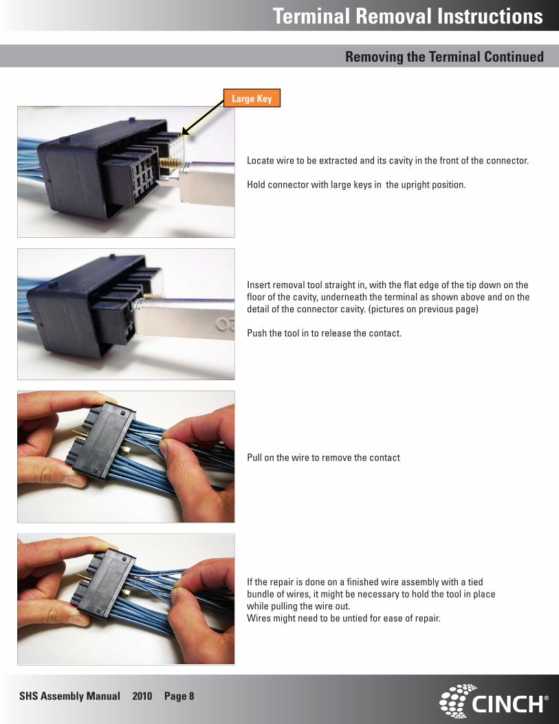
Locate wire to be extracted and its cavity in the front of the connector.
Hold connector with large keys in the upright position.
Insert removal tool straight in, with the flat edge of the tip down on the floor of the cavity, underneath the terminal as shown above and on the detail of the connector cavity. (pictures on previous page)
Push the tool in to release the contact.
Pull on the wire to remove the contact
If the repair is done on a finished wire assembly with a tied bundle of wires, it might be necessary to hold the tool in place while pulling the wire out.Wires might need to be untied for ease of repair.
Terminal Removal Instructions
Large Key
Removing the Terminal Continued
SHS Assembly Manual 2010 Page 9
Hand Crimp
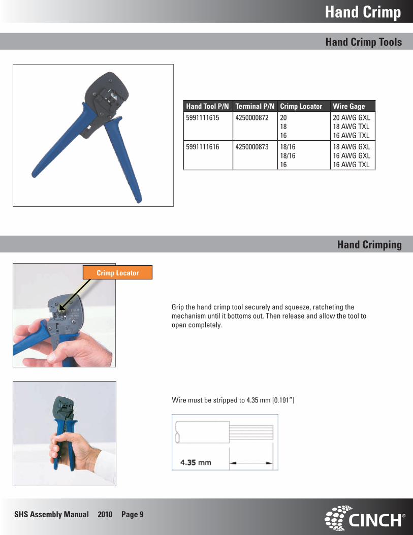
Hand Tool P/N Terminal P/N Crimp Locator Wire Gage
5991111615 4250000872 20 1816
20 AWG GXL18 AWG TXL 16 AWG TXL
5991111616 4250000873 18/16 18/16 16
18 AWG GXL16 AWG GXL16 AWG TXL
Hand Crimp Tools
Hand Crimping
Grip the hand crimp tool securely and squeeze, ratcheting the mechanism until it bottoms out. Then release and allow the tool to open completely.
Wire must be stripped to 4.35 mm [0.191”]
Crimp Locator
SHS Assembly Manual 2010 Page 10
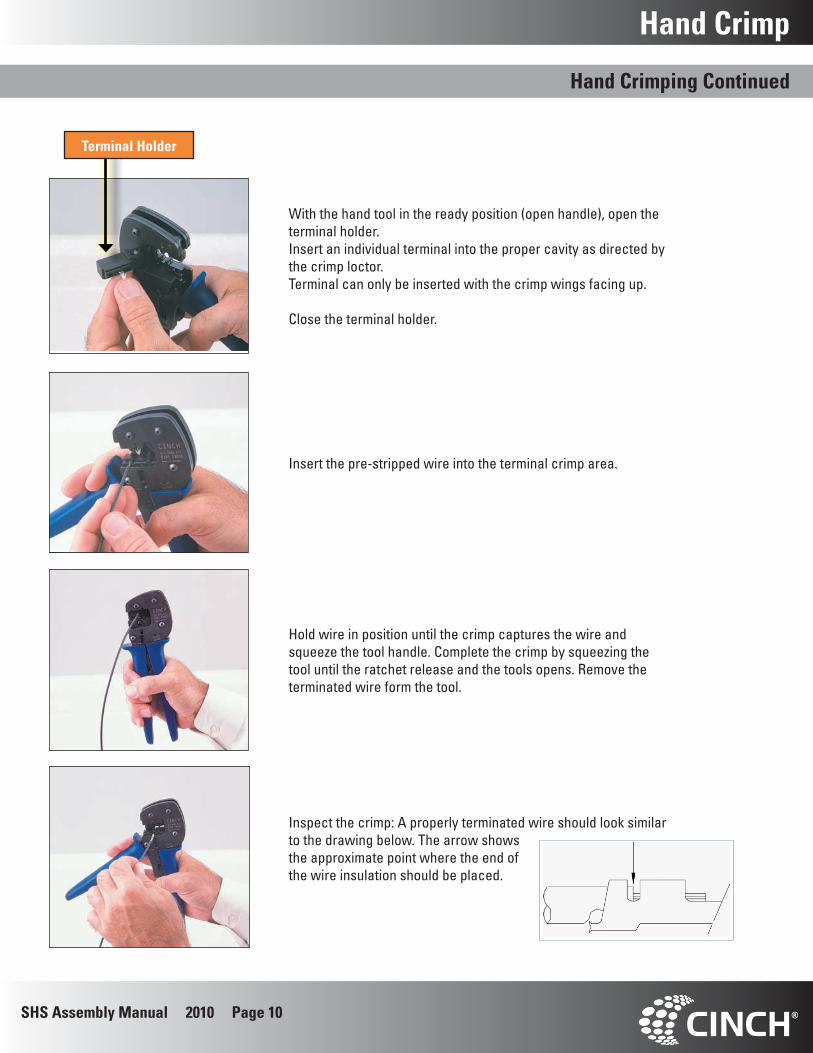
With the hand tool in the ready position (open handle), open the terminal holder.Insert an individual terminal into the proper cavity as directed by the crimp loctor.Terminal can only be inserted with the crimp wings facing up.
Close the terminal holder.
Hold wire in position until the crimp captures the wire and squeeze the tool handle. Complete the crimp by squeezing the tool until the ratchet release and the tools opens. Remove the terminated wire form the tool.
Insert the pre-stripped wire into the terminal crimp area.
Inspect the crimp: A properly terminated wire should look similar to the drawing below. The arrow shows the approximate point where the end of the wire insulation should be placed.
Hand Crimp
Terminal Holder
Hand Crimping Continued
SHS Assembly Manual 2010 Page 11
Automated Crimp
Tool P/N Description
5991111621 Applicator for terminal 42500008725991111622 Applicator for terminal 42500008735991111623 Replacement punch/anvil kit for 42500008725991111624 Replacement punch/anvil kit for 4250000873
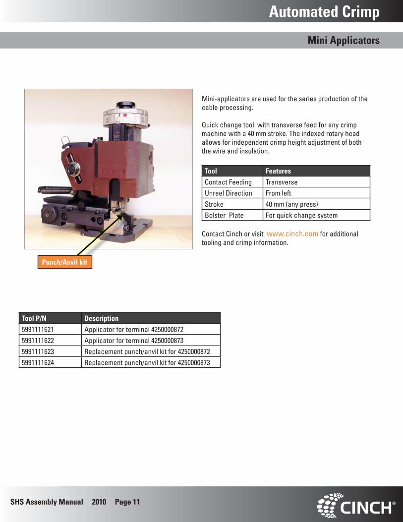
Mini Applicators
Mini-applicators are used for the series production of the cable processing.
Quick change tool with transverse feed for any crimp machine with a 40 mm stroke. The indexed rotary head allows for independent crimp height adjustment of both the wire and insulation.
Tool Features
Contact Feeding TransverseUnreel Direction From leftStroke 40 mm (any press)Bolster Plate For quick change system
Contact Cinch or visit www.cinch.com for additional tooling and crimp information.
Punch/Anvil kit

SHS Assembly Manual 2010 Page 12
P r o v e n E x c e l l e n c e
For over 70 years, Cinch has been a supplier of quality connector and interconnect prod-ucts to the computer, telecom, aerospace military and transportation industries. We are a multi-national manufacturer with facil-ities in the US, Mexico and the UK supplying
global customers.
Cinch applies its extensive expertise in in-terconnection technology to engineer and manufacture connectors, cables and har-nesses using state of the art technology and tooling. Mechanical design is accomplished using Pro/E 3D solid modeling supported by nonlinear and linear Finite Element Analysis
and Mold Flow software.
Our engineers utilize in-house capabilities in high frequency interconnect simulation, SPICE model generation and high frequency
testing to develop the optimum product.
All products are validated in Cinch’s first article, mechanical, electrical, and environ-mental test facilities ensuring the finished products meet our customers’ most stringent
specifications.
Simply stated, your connectors are manu-factured in state of the art facilities that are committed to customer satisfaction and con-
tinuous improvement.
www.cinch.com
Americas and Asia
1700 Finley Road
Lombard, IL 60148
USA
1.800.323.9612
630.705.6000