Embed Size (px)
Citation preview

8/20/2019 owners_handbook_tr4a.pdf
http://slidepdf.com/reader/full/ownershandbooktr4apdf 1/67
HANDBOOK
TR4

8/20/2019 owners_handbook_tr4a.pdf
http://slidepdf.com/reader/full/ownershandbooktr4apdf 2/67
IMPORTANT
IN THE
INTERESTS
OF
SAFETY,
THE
IMPOR.
TANCE
OF MAINTAINING
CORRECT
TYRE
PRESSURES
ANNOT BE
OVER
EMPHASTSED.
PRESSURESSHOULD BE CHECKEDAT LEAST
EVERY
TWO WEEKS
OR
1,000
MTLES
1600
MS.)
A N D
MAINTAINED
I N
A C C O R D A N C E
WI T H
RECOMMENDATIONS
GIVEN
ON
PAGE
58.

8/20/2019 owners_handbook_tr4a.pdf
http://slidepdf.com/reader/full/ownershandbooktr4apdf 3/67
TRIUMPH
TR4A
OWNERS HANDBOOK
Issued
b
STAN D ARD.TR I U MPH SALES LTD ,
COVENTRY,
ENGLAND
A member of
the Leylad Motors
Corporation

8/20/2019 owners_handbook_tr4a.pdf
http://slidepdf.com/reader/full/ownershandbooktr4apdf 4/67
FOREWORD
Surress,
rlre osDirution
of all human
pursuits.
has. in the
worlil of motor
sport.
bccomesynonymous
with
the
nane of Tr iuiph.
The-many
ourel i
obtained
by T,R. 's in intprnat ional
and locol competi t ions
aD?
ained
them ait enviabie rcputotion i7 *hi"h ,urry ownir is justifably ptouil.
The newestof the
Ttiumph
thotoughbreds,
he T.R.AA,
combines
na@ deuelopments
with
the well
prou.en rally
rcsred
eaturis
ol its
predicessors.
-Wc
welcom"
owaers to
on eDprb;ilening
circle of
enthusiasts
and uish them
many-pledsont'houri
of
motoring in
aililing na o honours
to a name
alreaily renowr.eil.
To
cnsurea continuance
of
thc superb
periormonce whieh
a
-T.R,4A.is
capable
ofgiuing. coupled
with reliability
anil economy,
regular
core onil dttention
ore
neccssary. Au
essennal inJormalton
ancl
thP pcrtods
allpr unr.n
attention
is" recokmended.,
are
cotutained,
in the
following
pages, Owners
ate aih;ised
to read
them carefully
and note
particularly the
ad'aiceon
lubrication'
New.parts or
accessories,
when needed,,
arc obtainable
only through authofiseil Triumph dealers, u;ho in
ad,ilition
to being trained
n
girn expert adnice
and attentiin,
are
also equipped
to utuilertahe
repairs
and
ooerhauls which
are bevonil
the scope
of most owners,
STANPART
Spare
Parts Service
Rept@ment
pdrs
are
nol supplied from
ltre facrory.Iirect
ro the
gen€ral
public,
but are
diEted throush
Distributors who,
id turn, supplv
their
cenuire spe parls are markered under rhe uade
marl Sldpan
an<tcaiiy rhe same
gu&mlee
as lhe
orieinal
parr.
The" same
high
qualirv
dalerial is: u$d dd rhe srricLed
aeuracy mainrsined
duritrg muufacture, you are advi$d. (heeibre. ro iosist on the use ol Lbese ans shouro
iliii 1.;, i,ti.;;
ii-""1,"".v.^'i;];;-b.;;i.i;iii"t
d. noirc'arrv
rhe trade
nrk stanpa(
qil
invaridare rhe
eueant@
if nlted 10
vou.
vehicre.
The .lescriorions and iltu{rarions
aDDearins
n rhis boor
are nor bindine.
The MANUFACIURER,
therefore.
rcFru€s
$e rishl-$hilst
*li', ' iiii if,l
"r;liil-i."'ii'Li
,liiii' iriiiir":t'ii.i,'
desribed atrd
irrusrar;d
-
ro
make at atry ride.
ivithour Decas&lv
brinsitre.rhis
book
;;:6:a'"i.'5ffi;";ii;;;i
i;
;"f;;';G;ori s
aeenea
oaveueot
ror imp.oveFeat
or fo' itrv meufactu'ing
or comerciar
r€ason'

8/20/2019 owners_handbook_tr4a.pdf
http://slidepdf.com/reader/full/ownershandbooktr4apdf 5/67
CONTENTS
Pate
4
7
l0
l l
l 3
l 5
29
3 l
33
Instruments nd Indicatols
Switches
nd Controls ..
Heatingand Ventilation
Locks and
Keys ..
Ddving
Reconmendations
Routine
SeNicing
Cooling
System .. ..
Road Wheelsand Tyres ..
Running
Adjustments
..
ElectricalSystem .. ,.
soft Top ..
Surrey Top
Care of Bodywork
Recommended
Lubricants
GeneralSpecification
..
Road Speed ata..
..
Tyre Pressures
Index
Pate
40
46
48
5 l
52
54
5'l
58
63
IMPORTANT
In
all
communications elating to
Service or Spares
please quote
the
Commission
Numb€r
(Chassis
Number),
and Paint and Trim Numb€rs
I-OCATION OF CO]IIDtrSSION
AAID
LINIT
]\{IMBERS
Commission,
aint and
Trim Numbers-On
Scuttle
Panel.
(May
be seen
by lifting the bonnet.)
Engine
Number-On L.H. side
of
Cylinder
Block.
Gearbox
Number-On L.H. side
of housing.
Rear
AxIe Number-On
face of HyPoid
Housing Flange.

8/20/2019 owners_handbook_tr4a.pdf
http://slidepdf.com/reader/full/ownershandbooktr4apdf 6/67
INSTRUMENTSAND INDICATORS
Fig. 1
(above)
Fig. 2
(below)
l, Fresh
Air Vcnt
Controls
2.
Tum
SignalControl.
3.
Tachometer.
4. Turn
Signal
ndicator.
5. Ignition
Waming
Light.
6, Hon Button.
7.
Speedometer.
8. Lighting
switch.
9. Water Temperature
Gau
10.
Oil
Pressure
Gauge.
I l. Fuel
Gauge.
12. Ash Tray.
13, Arruneter.
14. Facia Locker.
15,
FreshAir
Vent Control.
16. HeadlampDipper Switc
17. Clutch Pedal.
18. Brake Pedal.
19. Accelerator
Pedal.
20.
PanelRheostat
Switch.
21, WindscreenWasher
Con
22, Windscreen
Wiper
Switc
23. Heat Control.
24.
Gear Shift Lever.
25. Heater
Blower
Slvitch.
26. Heat Dist bution Contr
27.
Ignition/Starter
Switch.
28. Handbrake
Lever.
29. ScuttleVentilator
Contro
30. Choke Control.

8/20/2019 owners_handbook_tr4a.pdf
http://slidepdf.com/reader/full/ownershandbooktr4apdf 7/67
INSTRUMENTS
AND
INDICATORS
INSTRUMENTS
AND I]\DICATORS
The instruments,
indicators
and controls shown on Figs.
I
and
2,
and
indicated in brackets within the text,
perform
the
following functions:-
Tachometer
(3)
The
tachometer, indicates the
engine
speed in revolutions
per minute and is calibrated in divisions of 100, extending
to
6,000. The speed
range
within the red segment
s subject to
special precautions. Theseare giyen on page 14.
Turn Sienal Indicator
(4)
The green
flashing
indicator monitor light, glows intermit-
tently when the
direction
control is operated and
the ignition
is switched on. See
"T\rm
Signal Control" on page 9.
Flesh
Air
Vents
(1
and 15). Refer
to page
10.
Ignition Wamiry Light
(5)
The small
red warning
light glows when
the ignition
is
switched on and is extinguished when the engine
is
acc€lerated.
Should the indicator
continue to glow
when the engine s running
above dling speed
an electrical
fault is indicated li,hich should be
traced and
rectified
immediately.
Spe€dometer
7)
The speedometer
ndicates
the road speed of the vehicle
in
miles
per
hour and is calibrated
in divisions of
2, extending o I 20.
The fiqures within
the aperture above
the centre of the dial
may be fsed
to record individual
joumeys.
Provided
hat the
figures
are re-set to
zero at the beginning.
This is achieved by
pushing
up and
turning clockwise
he knob
which
extend
downwards
from behind the
instrument.
The figures within
the aperture below
the c€ntre of the dial
show the total
mileage of the v€hicle
ard may be used as a
guide
for
periodic
lubdcation and
maintenanca.
The High Beam indicator
near the bottom
of the dial glows
only when the
headlamp main beams
are n use. When the
diPper
switch is operated
tbe indicator is extinguished.

8/20/2019 owners_handbook_tr4a.pdf
http://slidepdf.com/reader/full/ownershandbooktr4apdf 8/67
INSTRUMENTSAND INDICATORS
Water Temperature
Gauge
(9)
Normal operating emperature
s reachedwhen the needle
registers n the
central sector of the dial. Should the needle
reach he highestmark,
stop the engine mmediately, llow it to
cool and check he evelof thecoolant n the radiator. When he
ignition is
switchedon
the
needlemovesslowly across ts scale,
taking up
to
one
minute
o reacha true rcading.
Oil Pressure Gauge
(10)
The oil pressure elief valve s set to
control the pressure t
65-75 b. per sq. n. at 2,000 .p.m. with normal
oil temperatures.
i.e.,
about ?O'C. During sustainedhigh speedoperati
resulting increase n oil temperature may
cause
he
oil pr
to drop. This will haveno detdmentaleffects
roviding
not fall below 30 b. per
sq.
n.
Severe peratingconditions,such as competitionwork
cause he oil pressureo fall below30 p.s.i., ndicating hat
temperature s excessive.Under these circumstances
cooler kit is recommendedo ensure hat a maximum
su
temperature f 125"C. s not
exceeded.
Fuel
Gauge
ll)
The fuel
gauge ndicates he approximate
contents
fuel
tank. When the ignition is switchedon, the needle
slowly across ts
scale aking up
to
one
minute to reach
a
reading which
it will maintain, regardless f vehiclemov
unril the ignition is
switched
otr
Ammeter
(13)
The ammeter s calibrated n amperes nd indicates h
of battery chargeand discharge.The charging ate s ind
when
the
pointer
moves o the left-hand side of
"zero
discharge.
) movemento the right.

8/20/2019 owners_handbook_tr4a.pdf
http://slidepdf.com/reader/full/ownershandbooktr4apdf 9/67
SWITCHES
AND CONTROLS
Fig. 4
Panel R.heostat
Switch
(20)
Turn the knob clockwise to illuminate the instruments.
Futher rotation
of the knob
diminishes
the light intensitv.
Operate
only when
the lighting
switch s
"on".
Lighting Switch
(8)
Move the column switch
lever
downwards to the fust Dosition
to illuminate
he side, ear , numberplate and centre nstrument
panel
lights. Move the lever down to the s€cond position to
illuminate the headlamps. See
Dipper
Switch", page 8.
Witrdsq€en
Washer
Control
(21)
Use the
windscreen washer cootrol in coniunction with the
windscreen
wiper.
Operate by pushing the conirol to spray clean
fluid
on
to the screenas the wiper bladesdispers€
he mud. If the
washer has remained unused or some ime, depress he control a
few times to charge
the
system.
Windsqeen Wiper Switch
(22)
Pull the switch knob to its first position
to operate the wipers
at fast speed and to
its
second
position to operate them at slow
speed.
Push the knob fully home to switch off, when
the wipers
will automatically return to the parked
position at the baseof the
windscreen. The wipers can only be
operated when the ignition
switch is
turned to
the
"ignition"
or auxiliary positions,
Ignition/Starter Switcb (27)
Op€rated
by a separatekey, the combined ignition and stalter
switch has
four positions. These are: l,
"Off",
in
which

8/20/2019 owners_handbook_tr4a.pdf
http://slidepdf.com/reader/full/ownershandbooktr4apdf 10/67
SWITCHES
AND CONTROLS
I. OFF
^
2. IGMTION
J
3. srART
4. AIIXILIARY
F l g . 5
position
t}Ie
key may be
withdrawn
;
2.
"Ignition"
;
3,
Start
;
4.
Auxiliary.
(See
Fig. 5.)
With
the
key in the
"Off"
position
(vertical),
urn the
key
clockwise
o
switch on the ignition
and
auxiliary circuits.
To operate the starter motor, turn the key further clockwise
against pring
pressure
nd
when
he engine
ires. eleasehe
key.
*hich
*il-t retum
to the
"lgnition"
Position.
t theenBineias
failed o start,
wait
until
the starter
motor hascome
o restbefbre
retumiug
he
key to the
"Start"
Position.
To
select "Auxiliary"
turn
the key anti-clockwise
from the
vertical
position.
This
will enable,
for €xamPle, hc
radio to be
used
witj\
the ignitioo
switched
off and, since
the key must
be
withdrawn
fronithe
switch to
lock the
vehicle, accessodes
annot
continue o
function.
Choke
Control
(30)
The choke
control is used
to enrich
the fuel
mixture for easier
startiog
rom cold.
The control should
not be
used f the engine
3
is warm.
and mav
not be oe€gssary
n walm
climates. F
structions
for
its'use are given
urider "starting'
on
pa
Headlamp
Dippr Switch
(16)
A foot operated ipper switch, ocatedon the oe-board
left of the itutctr
peAai,
enables
he ddver
to
quickly
low
headlamp beams
whilst
maintaining
full
conhol of th€ st
and othar
hand
controls.
When
the headlamps
are
illuminated,
see ighting
swi
page
7. the main
beams
may be lowered
by pressing
he
iwi-tch
and
releasing
r. To
retum lo the
main beam
Po
apain
Dress
he dipier
switcb
and
release r. The
main
p6sition
s indjcate'd'
y a
red
waming liSht near
the bott
ahe speedometer ial.
Hom Button
(6)
Operate
the
homs by
prcssing
the button
in the c€ntre
steering
wheel.
Overd
ve Control
(SPecial
Accessory)
When anoverdrive is fitted, the control is mounted on t
of the
steering
olumn
cowl
that
houses
he turn signal
c
Move
the lever
up
to engage
overdrive
and down
to rel
Before
using
he control,
see
page
14

8/20/2019 owners_handbook_tr4a.pdf
http://slidepdf.com/reader/full/ownershandbooktr4apdf 11/67
SWITCHES
AND CONTROL
Turn
Signal
Control
(2)
The turn signal
amps are controlled by a
lever
mounted on
the outboard side
of the steering olumn cowl.
Before making
a right-hand
turn, move the
lever
clockwise.
Move it anti-
cloc[wise
before
tuming left. When either left- or right-hand
turn signal amps are operating,a green ndicator light on the
facia,
flashes ntermittently,
Clutch,
Brake and
AcceleratorPedals
17,
18 and 19)
These are
conventional tems which do
not
need
further
explanation.
Gear Shift
Lever
(24)
AU forward gealshavesynchromesh ngagement.See
Fig
for the gear shift positions.
Reverse s engaged y moving t
gear hift
ever o the ight, ifting it and her
moving t rearwa
HandbrakeLever
(28)
To apply the
rear
wheelbrakes,pull
the handbruke evera
retain t in
position
by pressing he button on
top of the lev
Releasehe handbrakeby pulling
t slightly rearwards o free
pawl, then
allow the lever to move forward
to the
"OFF
position.
Seat
Adiustment
Fig.
7)
The driver's
and passenger'seats re adjustable
or leg rea
by moving
the lever
at
the front of each seat and sliding
t
seat o
the desired
osition,
allowing he
lever o re-engagen t
nearest djustmentnotch. The passenger's
eat backresthing
forward to provide
access o the rear compartment.
Radio Controls
For operating
nstructions ee he rudio leafletprovided
w
the set.
This is protectedagainstelectrical
damageby a
5 am
fusehoused n
the main lead union. Seepage40-WARNING

8/20/2019 owners_handbook_tr4a.pdf
http://slidepdf.com/reader/full/ownershandbooktr4apdf 12/67
HEATING
AND
VENTILATION
IIEATING
AND
The heater s designed o heat and distribute incoming fresh air,
or if dust and exhaust fumes are being admitted, thc intake
duct
may be closedand the heaterused o recirculate air aheady n the
vehicle.
Fresh air is admitted to the heater duct tirough the open
scuttle ventilator, This is opened by pulling
t}le ventilator
leyer rearwards and closed by
pushing
it forwards.
When the scuttle ventilato is closed, air
is
drawn
in tbrough
the open facia vents and recirculated by the heater unit, The
facia vents are opened by turning the handwheel, at
the side of
each
vent, forward.
When
the
scuttle ventilator is open,
cool fresh air is blown
out of the open facia vents and may be directed up or down,
or
may be cut-off by adjusting
the
handwhe€l.
There s no provision
for heatine the air blown from the facia vents.
Vf,NTILATION
The degree of heat given out by the heater unit is con
by the left-hand control on the
heater conhol panel. P
control fully out for maximum heat, or push it fully in fo
Intermediate positions give varying degees
of heat,
The blower switch on the ccntre of the panel cont
motor-driyen
fan which
stimulates
the flow of fresh air
outside when the vehicle is stationarv. and boosts the air c
tioo
when the vehicle s moving. The blower is opera
pulling the control to switch on, and pushing it to switc
The distribution of warmed air
is
effected
by
the right
control.
Pulling the contuol fully out directs air to the
in
of the vehicle. With the control pushed to the half
way
po
air is dire€ted to the screen or demisting or defrosting.
mediate
positions
direct ak to the screenand interior in v
proportions. With the control pushed fully home the sy
inoDerative.
Fig. E
10

8/20/2019 owners_handbook_tr4a.pdf
http://slidepdf.com/reader/full/ownershandbooktr4apdf 13/67
LOCKS AND KEY
LOCKS
Locks and Keys
Two setsof keysareprovided. One
key s used or operating
the gnition switchand door locks,and the other or
locking he
facia locker and
luggage
ompartment.
The
spare
set of keys
is housed
nside the rear lamp at
the passenger
ide. You are
advised
o record the key number for future reference, o
that
in the eventof
loss, eplacement eys may be obtainedwithout
diffculty.
Facia Locker
(Fig. 9)
The facia cubby box may be unlocked by turning the key a
quarter turn clockwiseand opened by depressing he locking
barrel and pulling
on the lipped plate.
AND KEYS
LuggageCompartment
Fig.
1l)
To open the luggage
compartment id, turn
the unlock
handlecounter-clockwise
o a vertical position
and raise he l
to its imit
beforeengaging he stay
n the slot
Provided.To close he lid, raise t slighdy o releasehe staywhich c
then be engaged
n its rubber retainer
on the boot lid suPP
assembly,
Lower the
lid
and
turn the handle, which
may
lockedby turning
the key a half turn
counter-clockwise.
Fuel Filler Cap
(Fig.
10)
The fuet
fitler cap, located forward
of the luggage ocker li
is opened
by depressing small
lever at the side
of
the
ca
Press he caD
o
close.
Fic.
l l
l

8/20/2019 owners_handbook_tr4a.pdf
http://slidepdf.com/reader/full/ownershandbooktr4apdf 14/67
LOCKS
AND KEYS
Door Ircks
Either door may be locked from inside or outsidc
irrespective
of
which
door
was last
used
as an exit, The mechanism uto-
matically prevents the inside handle being
set in the locked
position whilst the door
is
open.
This eliminates he possibility
of being locked out of the car in the event of the
key being
inadvertently eft inside.
Interior
Locking
To lock the door it must be closed ust. Only then will the
mechanism emit the insidehandle o be moved orwards.
The
handle
will
automatically
etum to the normal
position
as soon
as t is released.
IMPORTANT. Do not attempt to force the handle nto the
locked
position
whilst the door is.open.
Exterior Locking
When leaving the car, move the door
handle forward and
leave he
vehicle y the other door, which may then be ockedby
using he key as ollows :-
Inse the key n the ock and turn it approximate ly quarter
tum towards
the
shut-face.
The key will automatically retum
to rhe horizontal position from wheie t may be wirhdriwn,
when the dools are locked, pressurg
on the outside push
buttons,
which may be fully depressed, annot
force or damage
the lock,
l 2
To UDlock
Re-enter rom either
door by inserting
he key in th
and tuming
it approximately a
quarter tum away
fro
shut-face.The
key will again automatically
eturn to th
zontal position
to enable t to
be removed.
Lubrication
It will be beneficial, articularly
during
freezing
wea
fuifoduce a few droDs
of thin machine
oil into the latch s
the lock
key
slots
ai intervats
of not more than once a m
IMPORTANT. Urder no
circumstancesshould gre
applied
o the lock cylinders
or keys.
Bomet Release
To open the bonnet pull
the contuol situated
below
the right-hand side
of tlle
facia. The bonnet will
rise
sufficiendy
to enable the
fingers to be
inseded under
the rear edge o raise t to a
near
vertical position,
where
it will be supported by a
stay. Disengage
he
stay
from its recessbefore clos-
ing the bonnet.
Fie. 12

8/20/2019 owners_handbook_tr4a.pdf
http://slidepdf.com/reader/full/ownershandbooktr4apdf 15/67
DRIV ING
RECOMMENDATIO
DRIVING RECOMMENDATIONS
Running-in
The
mportanceof correct unning-in cannotbe too strongly
emphasized,or during he f,Ist 500milesof motoring, hework-
ing surfaces
of a new engine
are bedding
down.
Du
ng this
period
the valve
seatsstabilise,
ausing n
some
instances, light distortion and preventingproper seatingof a
valve.
Avoid
possible
damage esulting rom
such a condition,
by
having the compression ressures heckedearly in the life
of the engineafter
"running-in"
is completed.
If the
pressures
are unequal,
alve
grinding
s recommended.
Further attention o the valves houldnot then be equired or
a considerable ileage, r until thepressures aveagainbecome
unequal.
Whilst no specific speeds are recommendedduring the
running-in period,
avoid
placing
heavy oads upon the engine,
such as using full throttle at low speeds r when the engine s
cold. Running-in
should be
progressive nd
no harm will result
from the enginebeingallowed o
"rev."
fairly fast provided hat
it is thoroughly
warm
and
not
pulling hard.
Always
selecta
lower gear
f necessaryo rel ieve he engJne f load.
Full power should not be useduntil at least 500 miles have
been coveredand even then, it should be used only for short
periodsat a time. Theseperiodscan be extended s the engine
becomes
more responsive.After 1,000miles unning, he engine
can be considered s fully run-in.
Starting the
Engine
from Cold
Check,
and
if necessaryop up, the
radiator water evel a
the engineoil level. If the car hasnot beenused or several a
and
fuel has evaporated
rom the carburettors,
efill them
operalinghe
priming ever n he uelpump.
Theslight esista
ciuseswEen he loaichambers
re u .
Apply the
handbrakeand ensure
hat the gear ever is
"Neutral".
Pull the choke
control out to
its
stop and
tum t
key to the
"ignition"
position.
The gnition
waming ight sho
then
glow
and
the fuel gauge
hould egister he contentsof
t
fuel tank.
From the "ignition" position, um the key clockwiseaga
spring
pressureo operate he slartermotor.
lmmediatel)
eigini
hres. eleasehe key.
whichwill rerurn o the
"igniiio
position.
Should he
engine ail to start at
the first attempt,
not re-operate
he starterswitchuntil
the startermotor has
co
to
test.
As soon
as t starts,push
he choke o the
"half-in"
posit
and warm the engineat a
fairly fast dling speed
f approxima
1,500 .p.m.
This will cause he
ignition waming light to
extinguished,hus ndicating
hat the generator s
charging. T
oil gaugeshould ndicate he pressure f oil circulating. lf t
gauge
emainsat zero,stop
he engine mmediately nd
estab
the cause.
Failure to do so may
result n seriousdamage o t
eDgroe.

8/20/2019 owners_handbook_tr4a.pdf
http://slidepdf.com/reader/full/ownershandbooktr4apdf 16/67
DRIV ING RECOMMENDATION S
Cylinderwear s minimized fthe engine s warmed
up quickly
by driving away as soon as oil is circulating after
stading the
engine. Do not race he
engine o speedup the process ut, if
possible,maintain a speedof approximately 5 m.p.h.
until the
chokecan be
pushed
ully in.
In
warm
climates, seof the choke
may be unnecessary. void the use of full throttle during the
warmiog-up period. A themostat incorporated n
the cooling
system
enables he engine o
be
warmed
up quickly from cold.
Starting with the Engine Warm or Hot
When
re-starting
a hot engine,depresshe accelerator
edal
to about one-thirdofits travel
beforeoperating he starter witch.
The choke onrrol houldnot beused.
Recornmetrded peed Limits
Avoid over-rewing,particularly n the owergears.The driver
is advised ot to drive he
car continuously tengine peeds bove
5,000 .p.m.
in
any gear. However,whilst accelerating
hrough
the
gears
t is
permissible
o
attain 5,500 .p.m. for short periods,
these peeds eing ndicated
by the beginningand the end of the
red segment n the tachometer.
When an overdrive
s fitted, do not change rom overdrive
to normal 3rd or 2nd
gears
t
engine peed xce€ding ,500 .p.m.,
otherwisedamagemay result rom
"over-rewing".
OverdriveUnit (when fitted)
Ao overdrive nit senes
asa convenientmethodofproviding,
at wili, a numericalll ower
overallgear atio ro redice enginl
speedand wear,and to efect fuel
economy,
t4
The Laycock de Normanville
overdrive unit incor
an
epicyclic gear train which is engaged,
o give ov
condition,
by a cone clutch moving under the influenc
hydraulic
pressuregenemtedby a small piston pump.
pressure s released, ia a control valve, the
clutch is r
and held in direct drive by compressionsprings,
directional roller
clutch enables he change nto, or
overdrive o be made when ransmitting
ull power,with
of road
speed.
The hydraulic
control valve s linked to an electro-m
solenoidwhich s operated, ia
a
relay,
by a two-positio
mounted
on the stee ng column.
Greatestbenefit
will
accrue rom
judicious
use of th
drive, the
governing
actor
being
that
the vehicleconti
run easily without sign of engine labouring, combin
the ninimum
amount of throttle openingnecessaryo m
this condition.
Suggested
inimum
engagementpeeds re:-
Top gear 40m.p.h
Third gear
30m.p.h
Do not change rom overdrive to normal drive
at
speedsn excess f 4,400 .p.m.
The above disengagementpeedcorresponds ppro
to peak revs.
n
norrnal gears. Disengagement f the
a speed higher than that
stated
may
cause damag
"over-revving".

8/20/2019 owners_handbook_tr4a.pdf
http://slidepdf.com/reader/full/ownershandbooktr4apdf 17/67
ROUTINE SERVICIN
ROUTINE
This section describes he lubrication and servicinq require-
mentswhich are neaessaryo maintain be vehicle n g6od order
and ensure trouble-free motodng. All points desc bed should
receive attention at the prescdbed intervals,
Engrne
When a new car is delivered, he engine sump contains a
special
unning-in oil
which should be retaineduntil the com-
pletion of 1,000miles. Although the level may not reach he
high mark on the dipstick, he
quantity of oil
is
sufficient
or
the
running-in pedod.
Provided
the level is maintained between
the low and high marks on the dipstick, during this period,
topping-up
s unnecessary.
At the
"Free
Seryice",
he running-in oil is drained
and
the
sump
replenishedo the leyel
of
the high
mark on the dipstick,
with one of
the
approvedoils recommended n pages 2 and 53.
Gearbox.
OYerdriYeand Rear
Axle
Rear
axles,gearboxes nd overdriveunits fitted to new cars
are filled with a special oil, formulated to give all necessary
protection
to new gears. This
oil should
not
be drained but may
be topped up with any
of
the
approvedoils
listed
on pages 2
and 53
against he
appropriateuDit.
SERYICING
Lubrication
When carrying out the
following maintenaDce
work, th
importance of using only high grade lubdcants is yita
important and canrot be over emphasised
These lubricants have mainta,ined a high standard
quality over
many
years and are
recommended
on
after extensive ests in collaboration with the oil compan
concemed. n count es where heseoils are unobtainable,u
similar
high
grade
oils having the same characteristics,
PreYentiveMaintenance
To ensure continued emciencyand prolonged vehicle if
the maintenanceoucher chem€, roduced y Standard-Tr ium
engineers, fers a carefullvdesigned
lan
of lubrication equir
mentsand adjustment hecks t predetermined eriods.
Operatedby all Standard-Triumphdealerc,and specific
recommended
o
ownerswishing o obtain the greatest leas
from thei motoiing, the schemenvolves he use of a sedes
Maintenance
Vouchers
ontained n a booklet suDDlied ith th
car.
ServiceOperations ppropriateo mileage r
periods
time are isted on pages
preceding
he vouchers.
The space rovidedon the counterfoilofeachvoucher hou
be i lled n by theowneranddealer o constituteproof of regu
seryicing,
should his
be
required when
making a claim und
the wananty, or when selling he vehicle.

8/20/2019 owners_handbook_tr4a.pdf
http://slidepdf.com/reader/full/ownershandbooktr4apdf 18/67
ROUTINE
SERVICING
FREE
SERVICE OPERATIONS-
Radiator
Level
Engine
Sump
Cylinder
Head
Fue lPump
. . . .
CarburettoIs
Accelerator
ontrols,
linkage,
pedal,
ulcrum ..
Fan
Belt
Valves
Manifolds .. ..
Oil
Filter
Clutch
PedalPivot .. ..
Master Cylinder
Hydraulic
Pipes
Gearbox
Overdrive
RearAxle
.. ..
Universal
Joints
Lower Steedng
Swivel .,
wheel Alignment ..
..
Steering
Unit Attachments
and
"U"
bolts .. ..
Tie Rods and
Levers
l6
Check
Drain/refill
Check
tightness
Clean ilter
and sediment
chamber
Top up dashpots
Adjust slow
running
oil
Adjust tension
Adjust
clearanc€s
Check tightness
Examine
for
leaks
Lubricate
Check;
top
up
Check
leakage
Check
level-top up
Check
level-top
up
Check
tightness
Lubdcate
Check by
condition
of tyre treads
Check
tightness
Check
ightness
Handbrake
Cable
Linkage..
Hydrautic
Pipes
Master Cylinder
Pedal
Pivot .. ..
Brakes
HandbrakeCable
..
..
Battery
Generato ..
..
Generator
and
Starter
..
Distdbutor ..
..
Sparking
Ptugs
Headlamps
.
..
L i g h t s ,
H ea t e r ,
s c r e e n
washer, Wiper
and Warn-
ing Equipment
..
..
W h e e l N u t s , .
. .
Tyrc
Pressures
Door Strikers,
ocks,
Hinges
Body Mounting
Bolts
. .
Door Handles,
Controls
and
windshield
Lubricate
Check for leakage
Check/top
up
Lubricate
Adjust
if nocessary
Adjust
if necessary
Check/top
up
Lubricate
reax
beaing
Check
charging
rate
Chack
fixing bolts
for tight
Lubdcate
and adjust
points
Clean
and reset
Check alignment/adjust
Check
operation
Check
tightness
Check/adjust
Check
operation/oil
Check
tightness
Wipe clean

8/20/2019 owners_handbook_tr4a.pdf
http://slidepdf.com/reader/full/ownershandbooktr4apdf 19/67
ROUTINE
SERVICIN
PERIODICAL
ATTENTION
Engrne
Prior
to starting
out on a long run, or every
250 miles,che
the level of oil in the engine sump,
fust making sure that the c
is standing on level ground. If the engine has been unnin
wait a few minutes
o allow the oil to drain back
into the sum
Before checking the
level, make sure that
the car is standi
on
level
ground.
The dipstick
l)
may then be withdrawn,wip
cleanand pushed ully home before
withdrawing
t for readi
Should the
level be at the lower mark on
the dipstick, 4
Pi
(4
8
U.S.A.)
(2
3 litres) will be
required for topping up
v
the cap
(3).
Radiator
water l,€Y€l
The level of water, visible through the translucentplas
reservoirmounted orward of the radiator,
shouldbe maintain
at least
"half
full" by adding soft
water,
when required,
the
screwed
cap.
Should he
reservoir e allowed o empty,
emove he radia
filler cap,
(2)
Fig. 13, completely
ill the radiator,
rePlace
cao and fill the rlastic reseryoir.
CAUTION. If the engine
s hot, avoid danger
rom scalding
exercising xtreme arewhen emoving he radia
filler cap. Tum
it
a
half-turn and
allow press
to be fully released before
comPletely
remov
me cap.
ig. 13

8/20/2019 owners_handbook_tr4a.pdf
http://slidepdf.com/reader/full/ownershandbooktr4apdf 20/67
ROUTINE
S E R V I C I G
Tyres
The
maintenanceof corect tyre
pressure
s
an
important
factor
governing yre life,
steeringbehaviour aod suspension.
It is, therefore, mportant
that a checkon tyre
prcssurc
s made
regularly at periods
not
exceeding ne month,
and the losses,
due to diffusion, are n-udegood. Correct tyre pressures re
given on page 58.
Adjust the pressures hilst
the tyres are cold,
i.c., belore a
run. As the tyreswarm
up their pressures
ay ncrease s much
as 5 to 6 lbs. per sq. n. depending
pon the type of tyre and he
severityof driving.
CAUTION,
Never
bleed a warm
tyr€ to the recommended
pressure.
Battery
(Monthly)
Examine he level
of the electrolyte
n the cellsand, if neces-
sary, add distilled water
via the plugs
(4)
Fig.
13, o bring the
Ievelup to the
top of the
sepamto$.
The useof a Lucas
Battery Filler will
be
found
helpful when
topping-up.
Ensure hat
the Battery Filler is 6lled with distilled
water
and
nsert
it into
a filler
plug
orifice until it
restsgently on
the separaton.
Sufficientwater
will pour into the cell to
bring
the electrolyte
o its corect
level. Check eachcell
in turn.
l 8
IMPORTANT.
Never usea naked ight
when examin
ng the
battery, as the
mixture
of oxygenand hydrogen
given off by the battery
c a n b e
d a n g e r o u s l y
explosive.
Fig.
14
Examine he battery terminalsand, if necessary, lea
coat them with
petroleum
elly.
Wipe away any
foreign m
or
moisture froni the top
of the battery and
ensure ha
connections
nd nxings
are cleanand tight.

8/20/2019 owners_handbook_tr4a.pdf
http://slidepdf.com/reader/full/ownershandbooktr4apdf 21/67
ROUTINE
S E R V I C I
Brake and
Clutch
Master Cylinders
Fig.
15)
(Monthly)
Wipe hemaster ylinder
aPS lean.
emovehemand
check
the lui d evel n
the clutchand brake
master ylinder
eservoirs.
Ifnecessary,
op up the
fluid until it is evel
with the alrow on
the
side
of the reservoirs.
NOTE. As thebrakepadswear. he leyelof fluid in the master
cylinder
alls.
^
The
addition of fluid
to comPensate
or
oad wear
is unnecessarv. Should
the level have
fallen
ippreciably,
check
he tondition of
the
Pads.
If their
condition
s satisfactory stablish
he causeof
lossand
reatify the defect
inlmediately. Refer
to Page 38,
"Ble€ding the Brake and Clutch
Hydraulic System".
6,000
MILES
At 6,000 mile
intervals, carry
out
the work
listed und
PeriodicalAttention,
and the
following
additional
work.
Chassis Attachments
Check
the tightness
of all bolts
and
nuts,
Particularly
front and rear suspension,he steeringand the wheel nuts
Equipment
'Check
the operation
of
the l ighls.
heater.
wiPers. cr
washerand
wamlng equlPmenr.
Wheel Aliqnment
Check
-the
front
wheel track
alignment
(front
and
re
independent ear
suspension
model)
if tyre
wear is unev
Inner
Drive Shaft Joints
Lubricate f
nipples re
Provided.
Propeller haft
(Fig.
I6)
iubr ica te hesp- l ine :
nd
he bear ing
ssemblyt each
of
the propellershaft
by
forcing grease
hrough
the nipPles
A
and
"B" if t hese re provided.
Fig. 15
Fig.
16

8/20/2019 owners_handbook_tr4a.pdf
http://slidepdf.com/reader/full/ownershandbooktr4apdf 22/67
ROUTINE
SERVICING
Chanse
Engine
Oil
Fir aueiase
riving
conditions
rain
and
re6ll
he oil
sumP
with rhe
appr-opriate
-rade
f oil
at the
end of
each 6.000
mile
oeriod.
ieduci
this
period
for the
lollolling
unfavourable
conditions:
(a)
Frequent
stoP/start
driving.
iur
sttoi,
iourneys
uring
cold
weather.
sPecially
he n
appreciable
ngine
dling
s nvolved.
(c)
R1'gular
use
ofroads
producing
extreme
dust'
If the
vehicle
s used
or competition
or
sustained
igh
speed
work.
use
of
higher
viscosity oils
is
advised
because
f
the
increased
ojl
teriperature.
Additives
which dilute
the
oil or
imoair
its efficieniy
must
not
be used.
The
sump
drain plug
is
shown
arrowed,
Fig.
17.
Brake Pipes
Chec{
or
leakage
nd
or clearance
o
Prevent
heirchafing
Front
Brake
Adiustment
The
disc
brakes,
itted
to
the front
wheels
are self-adjusting
and
need
replacement
hoe
Pads
when
the
linings are
reduced
to approximately "
thickness.
Rear
Bmke
Adiustment
Fig. 18)
Each
ear
brike
s
provid;dwith
a small
djusler.
).
which s
accessible
hen
he road
wheel
s removed.
To adjust
he shoes,
turn
the adiuster
clockwise
until
the shoes
are
hard against
he
drum; then"slackenhe adjuster y one
notch
ncrements
ntil
the
drum
is free
o
rotate.
Handbrake
Adiustment
Adiustmeni
f
the rear
brake
shocs
uromatically
e-adjusts
the ha;dbrake
mechanism.
20

8/20/2019 owners_handbook_tr4a.pdf
http://slidepdf.com/reader/full/ownershandbooktr4apdf 23/67
ROUTINE SERVICI
Fis. 19
Ignition Dishibutor
(Fig.
19)
Release
le clips and remove
the distributor cap and rot
arm. Detach
the contact breaker points and
clean their
conta
faces with a fine
carborundum stone. If all trace of pittin
cannot bg
romoved, fit new contacts,
Using a small screwdri
in the slot (2),adjust he movingcontactso hat when he cont
h€el is on
the peak of the cam a 0
015" feeler gauge may
insertedbetween he
contact faces
7)
;
then tighten the screw
(
Apply a few drops
of thin oil around the edge
of the
screw
to lubricate
the cam bearings
and distributor spindle, Plac
single
drop of clean
eogineoil on the pivot
(6).
Smear he cam
with engine oil.
A
squeak
may occur when the cam
is
dry.
Refrt the rotor arm and ensure that the distdbutor cap
clean
and the c€ntral
carbon brush
is free in its housing. Re
the cap
and secuie
t to the distributor,
Carbuettor
Dash Pots
(Fig.
20)
Unsqew
the plug from the
top of each carburettor and wi
draw the plug
and damper
assembly. Top up
the damper chamb
with the curent
gradeof engine
il. The oil level s correctwh
utilizing
he damper
as
a
dipstick, ts threaded
Plugis+"
above
dash-pots
when resistance
s felt. Refit
the damper and plu
Using
an oil
can, apply oil to
the throttle and choke cont
linkages.
Check and
f necessary djust
the slow running
(Page
3
Fig. 20

8/20/2019 owners_handbook_tr4a.pdf
http://slidepdf.com/reader/full/ownershandbooktr4apdf 24/67
ROUTINE SERVICING
Fan Bett Tension
(Fig.
2l)
The an beltshould
esumciently
ight o drive
hegenerator
without uoduly oading
he
bearings.
Adjust the
belt by slackening
he
adjustingbolt
(5)
and the
generator ivots
3
and 4). Pivot
the
generator ntil the
belt can
be moved 'to 1"at ts ongest un (6). Maintaining hegenerator
in this
position, securely
ighten
the adjusting
bolt-
and the
two plvors.
Lower Steering Swivel
(Fig.
22)
Remove the
plug
(arrowed).
Fit
a screwed
grease nipple
anq-apply a grease
gun filled
with H)?oid
oil.
pump
the
gun
until oil exudes from
the swivel.
Rembve
the nipple
and iefit
the plug.
Upper Bal|
Joint
(Fig.
23)
. 4ppfy
u grease
gun fllled with
a recommended
grease o the
nipple
arrowed).
Pump rhe
gun
unlil grease
xudes rom
the
underside f the nylon"
wash; retainei
by lhe
grease ipple.
Sparking Plugs
^R^et9vele
sparking
plugs for
cleaningand
re-set he
gaps
to 0 025".
Clean he
ceramic
nsulators
and examine
hem for
cracks- r other
damageikely
to
cause
H.T."
tracking.
Test he
plugs before e-fitting
and renew
hose
which
are suspict.
Hinges, Catchesand Contols
Oil
can
ubricate
edalpivot
bushes.
oor
strikers, oor
an d
boot..lid ocks and
hinges
and rhe
accelerator
edalcontrols
ano InKages.
Fig. 21
Fie. 22
Fig.
23

8/20/2019 owners_handbook_tr4a.pdf
http://slidepdf.com/reader/full/ownershandbooktr4apdf 25/67
ROUTINE SERVICI
Air Cleaners
Remove
he air cleaners nd use an air
line
to remove
dust
from
between
he element olds. When refitting
the cleaners,
ensurehat
heholes bove he carburertor ane;selscre\
oles
are
correctly
ligned
with
corresponding
olesh the air cleaner
and gaskets.
(See
Figs. 24
and
25).
If the engine
s operatingunder dusty conditions,clean he
filters more frequently.
Valve
Rocker Clearances
Fig.
33)
Check
and, if necessary, d.just he inlet and exhaust
valve
clearanceso
0 010"
when cold. These ettings,
which are correct
for all operating
conditions, are
obtained
as follows :
1. Turn the crankshaftuntil No. I pushrod eaches
ts highest
point
;
then rotate thecrankshaft a further complete evolution.
TOP
2. Slacken he ocknut and nserta
0'010" eeler
gaugebetwe
No. I rockerand
valve
stem.
Turn the adjusterwith a scre
driver until
slight resistances felt as the gauge s mov
across he
valve
stem.
Tighten the locknut, re-check h
clearance
e-adjustingt if necessary.Deal with the rema
ing rockers n a similar manner,ensuring
hat
each rock
is correctlypositioned
before attempting o adjust t.
12,000 MrLEs
At 12,000mile
intervals,ca[y out the work listed und
6,000miles,and the following additional
work.
Crankcase
Breather Valve
(Fig.
26)
Slackenhe pipeclipsand
emove he
breather ipes.
Remo
the nut and bolt
retaining the
valve
and remove the valv
Disengagehe clip from the
-valve
body and
ift
out
the diaphag
Fig, U
Fis. 26Fig.

8/20/2019 owners_handbook_tr4a.pdf
http://slidepdf.com/reader/full/ownershandbooktr4apdf 26/67
ROUTINE
SERVICING
and
sDrins. Clean
the components
y
swillinA $em
in melhy-
lated piriis
(denatured
lcohbl).
Ensure hat the
breather ipes
are clean
and serviceable.
Reverse
he dismantling
sequence
o
re-assemble.
NOTE.
When the
breather valve
is cleaned,
emove the oil
filler
capandcheck
hal hebreatherole arrowed. ig.27) s
unobstrucled
nd
that the
oint
washer
s
serviceable.
Front Hub
Lubrication
and Adiustment
Check
and
if necessary djust
the front hubs every
12,000
miles
If the
car is
being used for competition
work, re-Pack
he
front
hubs
with greaieevery
12,000 iles.
This period-
may be
extended
o 24,000
miles or normal
use.
To pack he hubs
wilh
grease
-
JackuD
he ront of the car
and removeone
ront road
wheel.
Without
disturbing he hydraulic
PiPe
unions,
unscrew
wo bolts
securing
he calipei
to a plate screwed
o the
vertical link and
lift
thecaliDer
rom hedisc, ving
t to a convenient
oint
o
prevent
ir
hanging
y the attacbed
idraulicpipe.
Note the
number f
shims
ltted
between he caliper
and vertical
ink.
When wire-spoked
wheels are
fitted, remove
the splined
hub
extensions
y detaching he
nuts shown on
Fig. 28.
Remove
he hub grease
ap, withdraw
the sPlit
Pin
and remove
the slotted
nut and'1D" washer.Detach the hub assembly nd
outer
race
from the stub
axle. Wash all
trace of grease
rom
the
hub
and bearings.
Pack the
hub and bearings
with new grease,
working
it well into
the rollels.
24
Re-assemble
h€ hub and
r.aceso the
stub ade, securing
with the "D"
washer and
slotted
nut. SPin
the hub and ti
the nut until
resistance
s felt
to hub
rotation, then
slackeno
nut one
half flat and
fit a new
split
Pin.
Re-assemble
he
caliper
unit to
the vertical
link,
refitting any
shims
rem
dudng dismantling. Re-assemblehe sPlined hub extens
fitted).
Reflt
the road whe€l
and
lower the
jack.
Se€
War
on page 32.
Repeat
the above
operations
with
the oPposite
whee
8/20/2019 owners_handbook_tr4a.pdf
http://slidepdf.com/reader/full/ownershandbooktr4apdf 27/67
ROUTINE
S E R V I C
.Fic. 29
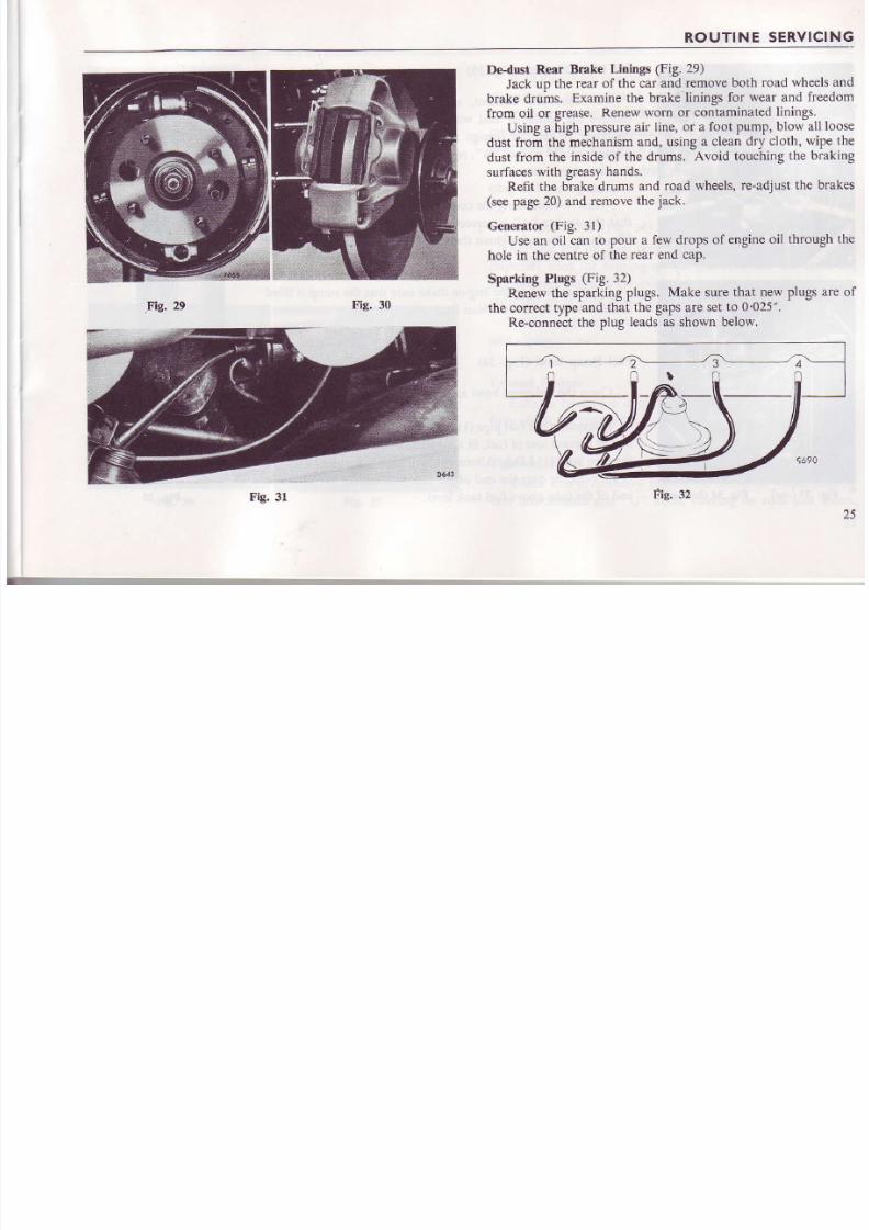
Dedust
Rear Brake
Linhgs (Fig.
29)
Jack up the
rear of the car
and remove
both road wheels
brake druins.
Examine
he brake inings
for wear and
freed
from oil or grease.
Renew
worn or contaminated
inings.
Using a
high pressure ir
line, or a foot
Pump,
blow all
lo
dust from
the mechanism
nd, using a clean
dry cloth,
wiPe
dust from the insideof the drums. Avoid touching he brak
surfaces
with greasy
hands.
Refit the brake
drums and
road wheels,
c-adiust he bra
(see
page
20)
and
remove
he
ack.
Generator
Fig.
31)
Use an oil can
o
pour
a few drops
of engineoil
through
hole n the centre
of the rear end
caP.
Sparking Plugs
(Fig.
32)
Renew he sparkingplugs.
Make sure
hat new
Plugs
are
the corect type and that the gapsare set o 0 025".
Re-connect
he plug
leads
as shown below.
Fig. 31
Fig. 32

8/20/2019 owners_handbook_tr4a.pdf
http://slidepdf.com/reader/full/ownershandbooktr4apdf 28/67
ROUTINE
SERVICING
Oil Filter
Element
FiB.
35)
To renew the
element, unscrew
the
securing
bolt "C",
rcmove the container
and withdraw
the
element.
Wash
th9
container
o remove
oreign matter
trapPed
by the
fllter
and
discard he old washer A", replacingt by a new one each ime
the element
s renewed.
When re-assembl ing
he container
and a
new element,
nstue
that the
washer
A"
is correctly
positioned
n its groove
n the
filter body.
Do not tighten
he boLt
C"
more
than is necessary
to effectan oil-tight
oint.
Before
e-stading he engine
makesure
hat
the sumP
s filled
to
the correct
evelwith clean resh
oil
Fuel Pump Bowl
(Fig.
34)
Clean he sediment
owl as
ollows:-
Disconnect
he uel
pipe
(1)
rom the suction
side
of the
Pump
and to
prevent
oss
of
fuel, it a
taPered
ubber or
wood
Plug
nto
the
pipe
bore
(+"
I.D.). Alternatively,
attach
one end
of a
length
of
rubber tube over
the end of the
fuel piPe
and tie
the oPPosite
end of
rhe tube above
uel tank level.
ig.
33
(top)
Fig.34
(bottom)

8/20/2019 owners_handbook_tr4a.pdf
http://slidepdf.com/reader/full/ownershandbooktr4apdf 29/67
ROUTINE SERVICI
Unscrew
t}Ie stirup nut
(2)
under the bowl, swing the stirup
to one side and
remove he bowl. Swill out the sedimentbowl and
wipe t clean,
To avoid damaging the glasssediment bowl when
refitting it,
tighten the stirrup nut only sumciently to ensurea fuel-tight j oint.
Re-conne4t
he fuel pipe and prime the carburettors.
Top-up c€arbox
(overdrive
if fitted)
The gearbox and overdrive urrits share a common filler orifice,
an
internal hansfer hole, permitting the units to attain a common
oil level.
With the
vehicle standing on level ground,
remove the oil le
plug
(shown
arrowed) and, using
a suitable dispenser such a
pump
t)?e oil can with
flexible nozzle illed with an extu
pressure
Hypoid)
lubricant,
top up the gearboxuntil
the
oi
levelwith the bottom of the iller plug
threads.
Allow surplus oil to drain
away before refitting
the le
plug
and wiping clean.
Top-up Rear Axle
(Fig.
36)
Remove the oil
level
plug
(shown
arrowed)
and,
using
dispenser sed
for
topping-up
the gearbox,and the same
i.e., exheme pressure
(Hypoid)
lub cant, top up the rear a
until
the
oil
is level with the bottom of
the filler plug threa
Allow surplusoil to drain
away before efitting he
evel
p
and wiping clean.
Exhaust System
Exhaust umes are detrimental o health.
Therefore,ca
fully
check
he
system
or leaksand immediately ectify defe
Tightness Check
Check
and if necessaryighten the universal
oints,
stee
unit attachments rld
"U"
bolts, steedng
ie rods
and
lev
Fis. 37
ig. 36

8/20/2019 owners_handbook_tr4a.pdf
http://slidepdf.com/reader/full/ownershandbooktr4apdf 30/67
ROUTINE
SERVICING
Stee
ng Utrit
(Fig.
38)
Remove
a sealing lug
from
the
toP of
the stee
ng unit
and
replace
t by
a grease
nipple.
APPIy
the grease
gun
and
give
5 strokes
only.
Remove
the
nipple
and refit
the
Plug
Over
greasing
an
cause
damage
o
the rubber bellows.
Water PumP
(Fig.
39)
Apply
a grease
gun
to
the
$ease
niPPle
and
inject grease
until
it exudes
rom a
hole
in the side
of
the pumP'
FUEL
OCTANE
REQT'IREMENT
Fuel octane
equirements
rerelated
o comPresslon
r
thus the
higher
the compression
atio, the
higher
the fue
requirementor maximumoPerating mciency. Thefue
requirement
research
method)
for
the TR4A
is as fol
9
: 1 compression
atio
Research
Octane
Number
97
m
Fuels
commercially
available
are
generally
-desig
Mixture,
Premium
and
Super,
he
octane
atings of
wh
between
Oil Companies
and
between
countries,
In
however,
he
octane
rating
corresponds
s follows:-
Premium
Research
Octane
Number
9'1 o
Super
..
Research
Octane
Number
l0
Detonation
esulting
rom
the use
of fuels
of a
lowe
rating
than specified
will,
if allowed
o continue,
caus
damage o an engine. Therefore,f a suitable
high oc
is not available,
the
ignition
setting
must
be retarded
tem
to suit.
(Se€
Ignition", page
41).
8/20/2019 owners_handbook_tr4a.pdf
http://slidepdf.com/reader/full/ownershandbooktr4apdf 31/67
COOLING SYSTE
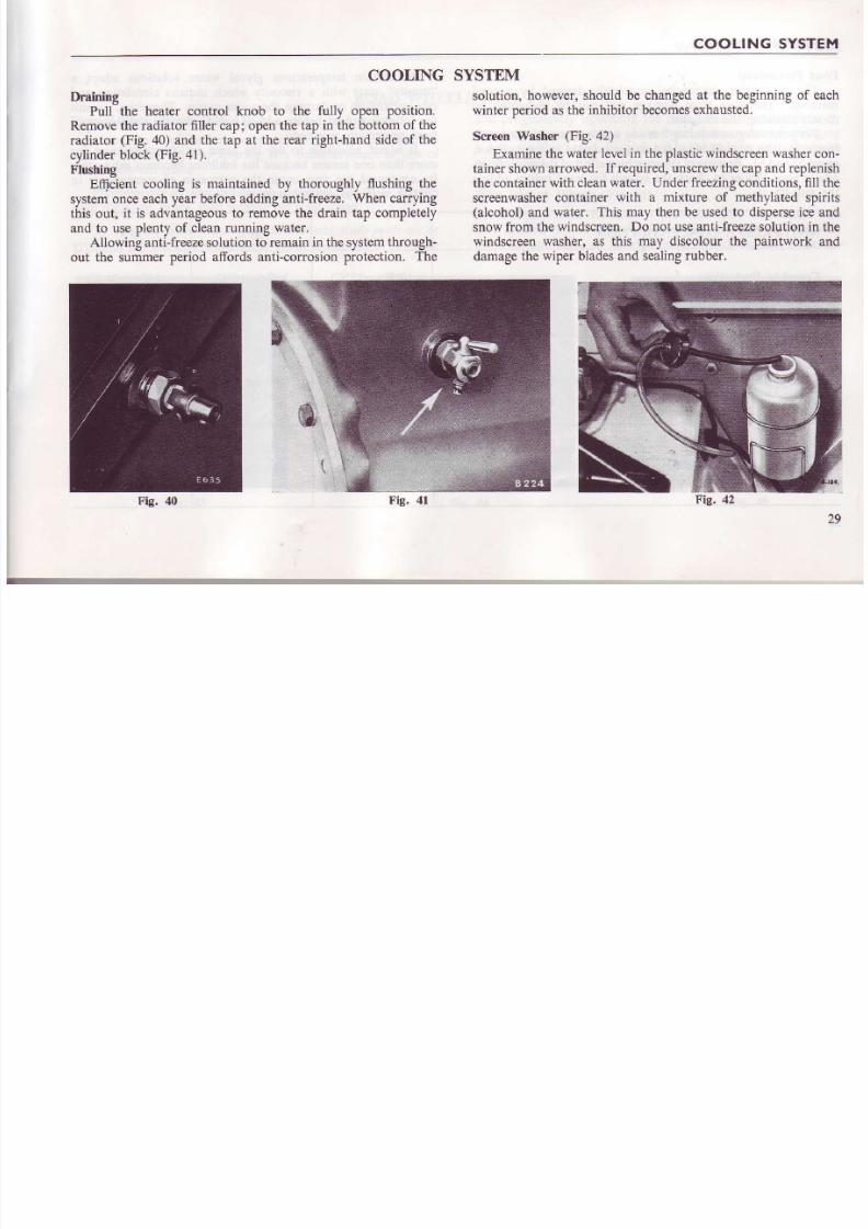
Draining
Pull
the heater cootrol knob
COOLING
to the fully open
position.
SYSTEM
solution, however,should
be changedat the beginningof eac
winter
period
as he ilhibitor becomes xhausted.
ScreenWasher
Fig.
42)
Examine he
water evel n the
Dlastic
windscreen asher
on
rainer hown rrowed.
frequired. nscrewhecapand epleni
the container
with cleanwater. Under reezing onditions, ill th
screenwasher
ontainer
with
a
mixture of methvlated
sDiri
(alcohol)
nd
water. This may henbe used o dispersecean
snow rom
the windscreen.Do
not
useanti-freeze olution n th
windscreen
washer, as this may discolour the
paintwork an
damage
he wiper bladesand sealing ubber,
Remove he radiator iller cap; open
he tap in the bottom of
the
radiator
(Fig.
40) and the tap at the rear dght-hand
side of the
cylinderblock (Fig.4l).
Flushing
Eqcient cooling
is maintained by thoroughly
flushing the
system
once each year before adding anti-freeze.
When carrying
this out,
it is
advantageous
o remove the drain tap completely
and to use plenty
of clean unning water.
Allowing antlfreeze solution
to remain in the system hrough-
out the summer
period affords anti-corrosion protection.
The
2

8/20/2019 owners_handbook_tr4a.pdf
http://slidepdf.com/reader/full/ownershandbooktr4apdf 32/67
COOLING SYSTEM
Frost Precautions
The
car
heater
cannot
be completely drained
by normal
methods. Therefore
ftost damage will
not be
prevented by
merely draining the radiator.
For your
safeguard uring reezingweather,
n approved
nti-
freezesolution should
be added o the coolant
in the radiator,
pages 2and 53. Because fthe searchingeffectf these olutions,
adviseyour
Dealer
o check he
system or leaksbefore
adding
the anti-freeze.
At certain temperatures
glycol water
solution
"mushy"
state with
a
viscosity
which impairs
circ
can immobilise
or damage the water
pump. Therefo
the
following chart
before adding anti-freeze,
or th
frost
protection
reouired.
It ls not
advisable o use the
same alti-freeze m
more than oneseason ecausehe inhibitor become
Its continued
use may cause he
corrosion of
com
contact with the
old solution.
ANTI-FREEZE
CONCENTRATION
30%
CompleteProtection:-
Vehicle may
be driven away immediate ly
rom
cold
lo'F
(
-
12'C)
(22
degrees
of frost)
3"F
(
-
16.C)
(29
degrees
of frost)
-4"F
(36
d
of f
Safe
Limit:-
Coolant in mushy
state. Engine may
be started and vehicle
driven away after short warm-up
period.
1'F
(
-
l7'C)
(31
degrees
of frost)
-8'F.
(
-22'C)
(40
degre€s
of frost)
I R o F
(50
d
of f
Lower Protection
Limit:-
Prevents rost danage to cylinder head, block and radiator.
Ensine
should NOT be started until thawed
out.
-14"F.
(
-26'C)
(46 degrees
of frost)
-22"F.
(
30.C)
(54
degrees
of frost)
-
) R o F
(60
d
of f
30

8/20/2019 owners_handbook_tr4a.pdf
http://slidepdf.com/reader/full/ownershandbooktr4apdf 33/67
WHEELSAND TYR
ROAD WHEEI.S
Pressed
Steel Wheels
(Fig.
43)
Using the
combination tool supplied in the
kit, remove the
nave plate
(hub
cap) by leveringat a point adjacent
o one of
the attachment studs.
Progressive\ slackenand detach he
wheel nuts
(R.H.
thread)
with the wheel bmce,
then remove the road wheel.
To refit the wheel, smear he attachment
studs with oil or
trease
o prevent
corosion, fit the wheeland secure
t
by
fitting
AND T\'RES
and progressively
tightening the nuts.
Refit
tbe nave plate
engaging ts m over two of the attacbment
studs and springi
it over the third stud,
by giving it a sharp blow with the pa
of the hand.
Wire Spoked Wheets
(Fig.
44)
A copper-faced hammer
is
provided
with cars fitted wi
wire spoked
(knock-on)
wheels o facilitate hub cap
remov
Tum the hub caps,on the dght-hand
side of the car, clockw

8/20/2019 owners_handbook_tr4a.pdf
http://slidepdf.com/reader/full/ownershandbooktr4apdf 34/67
WHEELS AND
TYRES
and the hub caps
on the eft-hand
sideof the
car,
anti-clockwise.
ro remove
hem. Derach
he wheel
y
pulljng
t
straight ff
th e
splinedhub. When
rentring
he
road whee-is.
meai
rhe hub
sp|nes wrl ' I l
ol l
or grcase
o
prevent
orrosion
and
possible
difficuhywirh wheel
emoval,
nsure
that
the hub
cips
ar e
fully
ightened
y srriking
he
ears
in the
approp aredirectionwith thecoDper-faced
ammer.
WARNING.
If the
vehicle
s fitted with
wfte-spoked
heels.
he
splined ubs.
when emoved,
ust
be re-fitted
o
the
coffect
side of the
vehicle,
.e..
he knock-on
hub caps
must tighten
n
the opposite
dircction
o
road
wheel otation.
Failure
to
ensure his
may
result n
a road wheel
coming
off its
splinedhub.
Always
ensurehat
the
hub splines
re
protected
during e-painring
perations.
Contamination
f
the splinesby paint may result n dimcult whe€l
removal
or ineffcient
tightening.
Fvery.6.000
iles. heck
he ighrness
f all
boks
and nurs.
parlcula \
the tront
and rear
suspension.
he
steering
nd the
wheelnuts.
Using
the Jack
(Fig.
45)
To raise
either
side of the vehicle
or road
wheel
removal.
proceed s follo\
s :-
l. Ensure hat the handbrake s appliedand one of the wheels
remaining
on the
ground
is cli6cked,
32
2.
Turn
the
jack
screw
anti-clockwise
o release
e
withdruw ack
from its
retaining
strap,
3.
Place he
ack
below
he chassis
rearward
of the
fr
and forward
of the rear
wheel)
and
engage
he
ho
handle with the screweye.
4.
Rotate
the
jack
handle
clockwise
o raise
the
ve
anti-clockwise
o lower,
5. To_lower
he
ack.
reverse
be
posirion
of the
ratc
and turn
it counter-clockwise.
TYRES
The tyre
pressures
hould
be adjusted
n
accordan
recommendations
ontained
n the
chart,
page
59.
Where
cars
are to be
used or
racing,
consult
the
tyre compan)
regarding
the need
fo-r ryres
of fu
cons[uctlon.
When
new tyres
are required
t
is essential
o fit
th
sarne type, The characteristicsof tyres vary conside
therefore
the four
tyres must
be
of ihe
sam; type.
8/20/2019 owners_handbook_tr4a.pdf
http://slidepdf.com/reader/full/ownershandbooktr4apdf 35/67
RUNNING
ADJUSTMENT
I
I
ZENITH.STROMBERG
CARBURETTORS
(SERIES
175.CD)
Starting
from Cold
(Fig.
5l)
The
mixture
is enriched
for cold starting
when the
choke
control is pulled. This oPerates a lever (6) which lotates the
start€I
bar
(20)
to
lift
the
air valve
(18)
and needle
(29),
thus
increasing
the
area of the annulus between
needle
and
jet
odfice.
Simultaneously,
a
cam on the lever
(6)
oPens he
throttle beyond
its
normal
idle position
to provide increased
dling speed,
according
to the setting
of the sqew
(4).
when
the motor
fues the increased depression
will
lift thc
air valve
(18)
to weaken the initial
starting mixture
and
Prevent
the enginestalling tbrough over richness.
While
the
choke remains
in action the car
may be driven
away
but
the control
knob should
be released or pushed
in
gradually
as
the engine attains
normal
working temPerature.
This
will progressively
decrease
he extent of enrichment
and
the degree
of throtde
opening for
fast-idle to the
Point
where
the screw
(4)
is out of contact
with the cam on
the choke
lever
and
the
thotde
is permitted to return
to the nomal
idle
Position
as
determined
by thc setting
of the throttle
stoP sqew
(3).
NOTE:
The
accelerator edal
should
not
be
dePressed hen
starting
from cold.
Normal
Ruming
With
the opening
of lhe butterfly
throttle, manifold
de
pression
s transferre-d,
ia a d llingi25)
in
rhe air
valve.
o
ihe chamber
(24)
which
is sealed
from the
maio body by
the
diaphagm
(16).
The
pressure
diference
between
chamber
(24)
and
tha
existiog
n the bore
(26)
causes
he air valve to lift, thus an
increasi
n engine
sDeed r
load
will enlarge
he effective hok
area since
hj air
valve lift is
proportional
to the
weight o
air
passinq
he
throttle
(27).
By
tfus means air
velocity an
presiue arop
across
the
jet
orifice
remain
approximate
constant
at
all speeds.
As the air
valve
(18)
rises
it withdraws
a taPered
meterin
needle
(29),
held
in the base
of the air
valve by
the screw
(10
from
the
iet
orifice
(19)
so
that fuel
flow is
increased relativ
to
the gr6ater
air flow.
Acceleratiotr
At any point
in the throttle
range
a temporadly
riche
mixture iC
needed at the
moment of
further
tfuottle
openin
To
provide
this, a dashpot
or hydraulic
damPer
s aEang
inside
he hollow
suide
od
(17)
of the air
valve.
The
rod i s filli
with S.A.E.20
oil to
within
a
+"
of
the en
of the
rod in which
the damper
(14)
operates.
When the
throttl
is opened,
he immediate upward
motion
of
the air
valve
resiited by
fiis
plunger diring
which time
the suction
o
depressionat the
let
orifice is increasedto enrich the mixtur
The downward
movement of
the air
valve
(18)
is assis
by the
coil spring
(15).

8/20/2019 owners_handbook_tr4a.pdf
http://slidepdf.com/reader/full/ownershandbooktr4apdf 36/67
RUNNING ADJUSTMENTS
ADJUSTMENT
Setting the
Idle
NOTE.
Although gauze
i1te6 are shown on
Figs.
4
paper element
filters are
fitted to
production
Two adjustment
screwsarc used
o regulate he idle
mixture. The hrottle stopscrew
3)
controls he speed,
adjusting crew
13)
determineshe qualityof air-fu
enlerjnghecylinders.
urning
he
et
adjusting crew
decreases
he mixture strength; anti-clockwise
will enri
With the engine
at nomal working
temperature
the
air
cleaner and hold the air
valve
(18)
down o
bridge
(28)
in the throttle bore.
Screw up the
jet
a
screw
(13)
a coin
is ideal for this purpose-unti
contactsthe undenide of the air valve. From this
turn dow[ the
jet
adjusting
screw hree tums. This e
an approximate
et
position from
which to work.
Run the engine
until it is thoroughly
warm
and a
stop screw
3)
to give an idle speed
of 600/650 .p.m
The idle
mixture is corlect when the engine beat
and egularand theair intake
hiss"
isequalo--n oth car
As
a
check, lift the air
valve a very small amount
a long thin screwdriver
and listen to the effect oll th
If the engine speed rises appreciably, the mixture is
and, conversely,
if the engine stops, the mixture is t
Properly adjusted,
the engine speed
will
either remain
or fall slightly on
lifting the air valve.
34
Big. 46
(top)
FE 47
(bottom')
R U N N I N G
ADJUSTMEN

8/20/2019 owners_handbook_tr4a.pdf
http://slidepdf.com/reader/full/ownershandbooktr4apdf 37/67
Adiusting
and Slnchonising
TrYin Carbuettor
Installation
Loosen
he
clampingbolts on
the tbrottle spindle
couPlings
between
hg
two instruments.
Next, unscrew
he throttle
stoP
screw
to
permit the throttle in each carburettor
to close com-
pletely.
id
tighten heclamping olts
on the
couPlings etween
lhe sDindles f
the two carburetlors.
Screw
n
the throttle stop screws
3)
to
rbe
Point
where the
eod o[
the screw
s
just
contactinghe stop
ever
attached
o
each
throttle spindle.
From this point
rotate
the stoP screw
in each carburittor
one complete
turn
to oPen the
throttles
ar equal
amount
to
provide
basis
rom which
final speed
of
idle can
be set.
Having
reconnected the
throttles and set
each oPen
an
ecual ambunt.
rezulate
he
iet
adiusting
cr€ws
13)
in lhe
in'srruments
s deiailed
undei the lieadirig setti ng
the ldle".
i.e,, hree ums down from the
Point
where he et orificecomes
into contact
with the baseof
the air valve
(18).
NOTE ;
Remember
hat the idle quality
dePends
o a large
extent
upon
the
general
nglne
onditionand
such
points
u. rappit
adjust;ent. spaik plugs,
and ignilion
iiming
should be
inlpected f
idling is not
stable. It is
also in-
portant
to eliminate
any leaks
in the
induction system
Float Chamber
Fuel LeYel
(Fig.
48)
To check
the
float level, remove the carburettor from the
engine
and
remove he float
chamber. Invert
thc carburettor.
Chlck
that the highest point
of
the float, when
the needle s
Fig'
't8
apainst
rs seating,
s 073"
(18
5 mm,)
abote the f ace of
t
m-ain ody.
Re-sit he
evelby carefully
ending
he ta8
wh
contacts he end of the needle.The additionof a thin f i
washer under
the needle
valve seat
will effectively
ower t
fuel
level.
a.7{
l8'5
M
RUNNING ADJUSTMENTS

8/20/2019 owners_handbook_tr4a.pdf
http://slidepdf.com/reader/full/ownershandbooktr4apdf 38/67
Eie. 49
Fig.
50
Jet Centralisation
Efrcient
operation of the
carburettor depends
u
freely moving
air valve and a correctly
cenhed needl
jet
orifice. The air valve may
be checked for freedom
by
the
valve
ith
the spring oaded
pin
{9t.
A
valve
a
fall freely ndicates
srick-ingalre.or
an off-cenrred
et.
the needie29) ouling he it orif ice. Recrify y reniov
cleaning
he
valve
and bore n
paramn,or by re-central
needle n the
et,
NOTE : When required,
the
jet
needlemust
be rene
one bearing he same
code number. The
shoulde
needle musi
be fitted flush with the lower
face
of
valve.
Procedure
l. Lift the air valve 18)and fully tightenthejet assem
2.
Screwup the
orifice adjusteruntil the
top of the
orif
is
ust
above he bddge
(28).
3. Slacken
off the
jet
assembly
12)
approximately
o
turn to release he
orifice bush
(23).
4. Allow the air valve
(18)
to fallt the needle
will the
the
orifice and thus centralise
t,
5. Slowly ighlen he
assembly
12).
checking
requen
rhe niedle emains
ree n the
orif ice. Cheik
biraisi
air valve approximately+" and allowing it t6 fal
The piston should then
stop furr y on the
bridge.
6. Re-set the
engine idling.
l6
RUNNING
ADJUSTMENT

8/20/2019 owners_handbook_tr4a.pdf
http://slidepdf.com/reader/full/ownershandbooktr4apdf 39/67
3.
Throttle rtop $rew 9. Sprins loaded
pin
I l .
"O
'
. ing
13.JeiadjustnE
c.e*
15. Coil
sprins
22. Inlei
hole
25,
Ai. valve drilling
26. Bo.e
28 B.idge
F i s . 5 1
3
R U N N I N G
ADJUSTMENTS

8/20/2019 owners_handbook_tr4a.pdf
http://slidepdf.com/reader/full/ownershandbooktr4apdf 40/67
BLEEDING
THE
BRAKE
AND.
CLUTCH
FII'DRAULIC
SYSTEMS
If
a pipe
oint
has
beenuncoupled,
or part
of the hydraulic
system ismantled,
he system
must
be bled o
expelair,
The
procedure
s
as follows:-
l.
Clean
he bleeder
ipple
and it a
piece
of
rubber ube
over t,
allowingthe
ube o
hang
naclean
ontainerpartially
i l ledwith
fluid,
so that
the end
of the
pipe is
below the level
of the fluid.
2.
Unscrew_the
leeder
ipple
one complete
um.
There
s only
one
bleeder
ipple
o each
wheel
and one
nipple on
the clutci.r
operating
ylinder.
The
position
of the
brake
bleeder ipples
is
shown
n Figs.
0
FRONI.
The
clutch
bleeder
ippie s
shown
n Fig.
17, tem
.
NOTE. The rearbrakebleeder ipplesaresituated t the op
of
the
back
plate,
and are
accessible ith
the
wheels
removed.
3. Fill
the
fluid
reservoir
before
commencing
he bleeding
operation,
and keep
t
at least
half-filled
durinq
the
whol-
operation,
therwise
ir wil l
be
drawn nro
the-
vsrem
ia
the
master
cylinder.
Do
not
use luid that
has
been
expelled
from
the
sysrem
or
mailtahing
the
level. Always
clean he
area
around
the
filler
cap
before removing
it.
4,
Depress
he
pedal
quickly
and
allow it
to return
without
assistance.
Repeat
this
pumping
operation
with a
slight
38
pause
between
each depression
f the
pedal,
Obs
flow
of fluid
being discharged
nto
the glass
ar
and
air bubbles
cease o
appear,hold
the pedal
irmly
do
securely
tighten
the bleeder nipple.
NOTE.
For bleeding
or replenishment
f the
system,
fluid that hasbeenstored n a container ealed
mosphere.
mmediately
bleeding
s
complete
residual
luid in
the container,
before
t is
agai
Engine
Beforo
filling the cooling
system
with
an anti-freeze
m
or after
the engine
has been
decarbonised,
check
the t
of
the cylinder head
nuts
and if necessary,
jghten
them
order shown
on Fig.
52.
Re-adjusthe valve ockerclearancess described n p
F g . 5 2
R U N N I N G
ADJUSTMENT

8/20/2019 owners_handbook_tr4a.pdf
http://slidepdf.com/reader/full/ownershandbooktr4apdf 41/67
Fig. 53
Fie .5{
STEERING
COLTMN
IMPACT
CLAMP
The T.R,4A
incorporates telescopic teering olumn
which
provides adjustment
for column length and protection
for the
driver
in the event of a collision.
To adjust the column length :-
L Slacken
he impact clamp
ock
nut,
(l)
Fig. 53, and unscrcw
the socketheadscrew
2)
with a *" A.F. socket ey.
2, Working
inside the vehicle, slacken the clamp nuts shown
arrowed on Fis. 54.
3. Slacken a
third clamp behind
the facia
Panel.
4. Move
the column
to the desired
Position
and
re-tighte
the two upper
clamPs.
5.
Using
only
6nger pressure
on the socket
key, tighten the
screw
2)
and secure
he locknut
(l).
NOTE. The steering
oluml will
be unable to
telescoPe
adjusted
to its
lowest position.
3
ELECTRICAL
YSTEM

8/20/2019 owners_handbook_tr4a.pdf
http://slidepdf.com/reader/full/ownershandbooktr4apdf 42/67
ELECTRICAI
A 12
volt negative
earth system
s employed
n all
circuits.
To safeguard
against
fire from
short circuits,
alwavs
dis-
connect
one
cable rom
the
battcry before
emoving
or disco,r-
nectingan electrical nit.
WARNING.
Ii the
vehicle is
to be
equipped with
a radio,
connected
o the
car electrical
ystem, nsure
hat
the
radio
is of
NEGATIVE
GROUND
POLARITY,
or seriousdamage
will result.
SYSTEM
Fuses
Fig.
55)
The use
unit, which s ocated
on the right-hand
sid
houses
operating nd 2
spare uses. Fuse
A2
pro
ins t tumentl luminat ion .he parL ing nd ra i l lamp
number
plare lluminarion
amps. Fuse
A.4
proreci
conlrolled y
}e
gnition
r tch.l.e..
lashingdirection
ig
peralure
nd uel
gauges.rake top amp5
nd he ip
below he use
nii
adJacento thehorn relal
mainhai
Failure
of a fuse is indicated
by all the
units pro
that fuse
becoming
noDerative. f the new
use ails
mm
the eguipment
n-d ssociatediring
musr
be examin
fault rectified
BULB
CHART
L
5
Fig. s5
ELECTRICAL
SYSTEM

8/20/2019 owners_handbook_tr4a.pdf
http://slidepdf.com/reader/full/ownershandbooktr4apdf 43/67
Ignition
Failure
of
the ignition waming
liSht will
not
Prevent
he
ignition
system
fuactioning
but the
fault should be
rectified at
the first
opportunity.
All high tension cables itted to the ignition system are made
from
carbon
impregnated
nylon or cotton
cords encased
II
rubber
or neoprene
o form a high
resistiveconductor.
Re-
placement
cables
must always
be of the same
tyPe.
Ke€p
the moutded
cover of the distributor
clean
by wiPing
it insid;
and outside
with a soft cloth.
Check that
the carbon
brush
on the
inside moves
freely. The contacts
must
be kePt
free from oil
or dust,
and a gaP maintained
at 0
015".
Ignition
Timing
(Fig.
19)
The nominal
ignition setting
given on
Page
54 aPPlies
o an
engineat
rest.
when
the engine s
running he
i8nition s
adianced
utomatically
o suit
varying onditions
Maximum
performanceof an
individual engine
may require slight
modi-
hcation
of the
nominal setting o suit
particular gades
of fuel.
To set the
ignition timing,
rotate the crankshaft
until the
hole in the
crankshaft pulley
flange is aligned
with the
Pointer
on the timing cover. With the distributor point gaP(7) set at
0.015"
(0
4
mm.), and
the vemier adjustmentset
in the centre
of its scale
(9),
slackeD
he distributor clamP
bolt and adjust
the
distributor
o
hat he
conlact
reaker
oints rejust ommenci
to open.
Tigh(en
hedistributor
lamP
olt
and olate
heknurle
ver;ier adiustment
crew
(5)
anti-clockwise
nril
one extr
division
appears
n
the
scale.
G€trerator
and Control
Box
The
generator
operates
n coniunction
with the
voltag
requlator"unit
hich
s adjacent
o-the
cut-out
n the contro
box.
A
fully-charged
battery
receiYes
low
charginB
curren
and a dischaieed
biarterv
high charging
current.
Additionall
the
cut-out
p[uents
the
batteiy
frorn-beiing
ischarged
hroug
rhegenerator,
hen
he generator
s
not charging.
n lhiseven
the ignition
warning
ight glows.
Maintenance
f the
coil
is restricted
o
keePinghe termina
clean and
free from
oil,
The Starter
Motor
The starter
brush
gear
and corffnutator
do
not normal
reouire ttention
or aionsiderable
eriod.
After
48.000mile
houever.
t is
advisableo
have he unit
serviced
l a
TriumP
or Lucas Service
Depot,
If
the starterpinion
ams
n
meshwith
the fl1vheel,
t may
b
released y
switching ff
the ignit ion.
selecting
oP
8ear.-a
rockins he car to and fro, or b y removinq he endcover rom
the sta"rter
nd turning the
squired
end
-of
the exposed
sha
in a clockwise
direction,
4
ELECTRICAL
SYSTEM

8/20/2019 owners_handbook_tr4a.pdf
http://slidepdf.com/reader/full/ownershandbooktr4apdf 44/67
30
- -
Q - - - - -
-----d.^--
-
42
Fis. 56
ELECTRICAL
SYSTEM

8/20/2019 owners_handbook_tr4a.pdf
http://slidepdf.com/reader/full/ownershandbooktr4apdf 45/67
l. Generator.
2.
Ignition Warning
Lamp,
3. Ignition Coil.
4. Distributor.
5. Control
Box.
6. Ignition
Switch.
7. Ammeter.
8.
Horns Fuse.
9. Horn
Relay.
10. Hom
Push.
11, Horns.
12. Starter
Motor.
13. StarterSolenoid.
14,
Battery.
15. Lighting
Switch.
16.
Dip Switch.
1?.
High Beam
ndicator
LamP.
18. Headlamp
High
Beam,
R.H.
19.
Headlamp
High Beam,
L.H.
20. Headlamp
Dip
Beam,R.H.
21. Headlamp
Dip
Beam,L.H.
22. lnstrument
lluminalion
Rheostat
23. FuseUnit.
24. Stop
Lamp
Switch
26.
Stop
Lamp,
R.H.
26. Stop
Lamp
L.H.
KEY
TO FIG.
56
27.
Ammeter and
Gauges
llumination.
28. VoltageStabilizer.
-
29. HealerBlowerMoror
lOprional
Swrlcn
l-_'...
30. Heater
Blower
Motor
J
'^"-
31. Temperature
ndicator
Gauge.
32.
Temperature
ransmitter.
33. Fuel Gauge.
34. Tank
Unit.
15.
Speedometer
llumination.
36. Tachometer
llumination.
37.
Reversing
amp Switch
I Ootionat
38. ReversinBamp i;" i;; '
19. Reversing
amp.
-J
" -
40.
ParkingLamp
R.H.
41.Park ing
anp
L.H.
42- Directi;n ndicator
R.H.
Front.
43,
Direction
Indicator
R.H. Front
Repeater.
44. Direction
Indicator
R.H.
Rear.
45.
FlasherUnit.
46. Direction
Indicator
Switch.
47. Direction
Indicator
L.H.
Front.
48. Direction ndicatorL.H. Front
Repeater.
49. Di;ection ndicator
.H.
Rear.
50.
Flasher
Warning
LamP
51. Windshield
WiPer
Motor.
52. WindshieldWiperMotor Switch
53.
Plate l lumination
amP
L.H.
54. Tail Lamp
L.H.
55.
Plate l lumination
amP
R.H.
56.
Tail Lamp
R.H.
FRANCE
ONLY
A1.
Fuse.
A4.
Switch.
A2. Horn
Relay.
,A5.
Horn
low note
B l . Re lav .
I ^ . - . , r .
- - . - , l v
82 . So leno id . t ^ - . , ^ -
tr. ii",i"
b"",..'
iPl,'l::
84.
Transmission
witches.J
"
-"
CABLE
COI,OUR CODE
B.
Black.
U.
Blue.
N. Brown.
G.
Green.
LG.
Light Green.
K. Pink.
P.
Purple
R. Red.
W. white.
Y, Yellow
4
ELECTRICAL
SYSTEM

8/20/2019 owners_handbook_tr4a.pdf
http://slidepdf.com/reader/full/ownershandbooktr4apdf 46/67
Headlamp
Alignment
The sealed
eam
s aligned n
the
vertical
Plane
by
turoing the
screw
at the top
of the lamp
and
in the horizontal
Plane
by
turning
$e
screw on
the side.
Alignment
of the high
beam
on one
lamp is best
carried
out
with the other lamp
covered
Maximum illumination is obtained, and discornfort to other
road users
s
Drevented,
v
ensuring
hat the lamp
beams
do
not
Droiect
bove
he horizbntal
hen he
vehicleifuuy
laden.
Adjristrients,
when
necessary,should
be entrusted
to a Dealer
having
beam setting
equiPment.
Light
Unit
Replaceme
The headlamps
are
fitted
with sealed beam
units
failure
necessitates
ight unit
renewal.
Remove
t
rim
by inserting
the
tool, provided
in the kit,
beh
and levering sideways
Fig.
57)
Remove the
Fig. 58, and
withdraw
the
rim to
release he
light un
distub
the
beam aiming
adjustment
screws
(2).
the plug,
Fig. 59.
44
Fig.
5?
Fig. 5E
Fig.
59
Fig. 6
ELECTRICAL
SYSTEM

8/20/2019 owners_handbook_tr4a.pdf
http://slidepdf.com/reader/full/ownershandbooktr4apdf 47/67
Front Dtuection
ndicator
Flashing
LanP6
(Fig.6l)
With
the aid
of a thin screwdriver
tuln back the
rubber and
remove
the
rim. This then
Permits
the glass
ens to be similarly
removed,
when le-assembling
he comPonents
it the glass
ens
tust.
RepeaterLanp
(Fig.
60)
Access
o the
bulb is
gainedby removing he
retainingscrew
and
disengaging
he ens rom
the etaining
iP. Pull
out
the bulb.
Tail/Brake Stop
and Direction
hdicator FlashiDg
Llmps
(Fig.
63)
Remove
three screws
and lift off
the lans, which is in
two
sections,
o gain access
o the
bulbs. The pins
on the tail/brake
stop lamp bulb
are offset and
cannot be fitted
incorectly.
Parking Lamps
(Fig.
62)
Twist
the lens counter-clockwise
nd
withdlaw
the lamp
front to gain access
o the bulb.
Plate llumination
Lamps
(Fig.
64)
Remove
the two screws
securing
the rim and
cowl to
the
over-rider, withdraw the lamP aPproximately2" and rcnew
the
bulb.
Battery
Keep the
terminalsclean
and
well covered
with
Petroleu
ielly
to
prevent
corrosion.
lf
rhe terminals
becomecorrode
'scripe
them clean
and coat
with
petroleum
elly
Fk. 61
Fig. 62
Fic .63
FA. 64

8/20/2019 owners_handbook_tr4a.pdf
http://slidepdf.com/reader/full/ownershandbooktr4apdf 48/67
BODYWORK
SOT-T
TOP
The
soft
op,
which
s
made
rom
P'V
C
material'
s suPPorted
by a hinged rame,which oldsdown into thebackof thecarand
is
retained
n
Place
bY
a cover'
Tonneau
Cover
(Fig. 70)
A
tonneau
cover
s available
as
an
optional
extra
The cover
pronid",
*"uth",
p.otection
or
the
vehicle
nterior
when
he
soft
top
is
remoued.
lt
incorPorates
ress
tuds
or
securing
o
the
ca'r
nd
has
zip astener
own
he
centre
hich
Permits
ccess
o
eitheror both oi the ront
seats
A straP
ori
the underside
f
the
cover
engages
pillar
lastener
n
the
nboard
side
of
the
Passe'ger
seat
rame.
ADDIV
ngine
il
sparingly
o the
oints
of the
fram
small '
rush.-
Work
rhe
oil
well
into
the
oints and
tb
away
all
surPlus
oil.
Hood
Lowering
(Figs. 65
to
69)
Release
he
toggles
etaining
he
loP
Release
he-
(three
ach
ide,
Jal'
ard
of
the
doors)
eruring
he ed
trooa
to
,ft"
body.
Push
he
header
ail
upwards
1n9
ttu
""tlitf"
no.Ottilt
"ssembly
begins
o
fold
Pull
the
hoo
;;;
;,h"
;;"
rail
(arrowei
Fig
67)'
Pull
the.
hoo
,"ui*u.a, to tl" nut over heboot lid, as hehoodsticks
r
,.
,tt.
fr.,ffu
olded
posilion
Fold
the
hood
foruard
i...o., i" lJ""o
turn
the
quarler
ights
n\
ards
l-i9
69)
aft",
f,a
Vou"l
rear
windo*
is free
rom
distortion
nd
tol-i.u,. 'r iuf
it
no,
raPPed
y
he
hoodsl
cks
arrowed
Retain
he
hood
n
Position
with
the
cover
Provided
as
ollows:
Attach the cover initially
to
the
outside
Pillar
.h";;-;;
Fig
69
before
engaging
he
remaining
Attach
each
strap
to
its
resPective
astener
o tne
D
of
the
well.
Maintenance
Maintenance
of the
soft
fabric
with
warm
water
and
the
toP
dry.
top
is
restricted
o
washing
the
a
non-caustic
oaP.
AlwaYs
wtPe
Do not use
detergents,
olish
or
fuel-based
leaners
s they
may
damage
he
abric
or afiect
he
adhesive
sed
n manufacture'
Obstinate
grease
marks
may
be
removed
by
using
a
cloth
moistened
with carbon
etrachlodde'
46
BODYWORK

8/20/2019 owners_handbook_tr4a.pdf
http://slidepdf.com/reader/full/ownershandbooktr4apdf 49/67
Fig.
68
Fis. 69
Fig. ?0

8/20/2019 owners_handbook_tr4a.pdf
http://slidepdf.com/reader/full/ownershandbooktr4apdf 50/67
BODYWORK
SI,-RREY
TOP
To
Fit
(Fig. 75)
Remove
thg
two
bolts from the undersideof the windscre€n
h""d*';;iL
"tta
tn" t*o
bolts
from
the
underside
of
the
back
iiniii
.".to,i"a,
and
lift away
the
roof
Panel'
oDen
out
lhe
surrey
op
lrame
and
enter
he rear
ends
of
the
r,u-Jinio
the
holes
n'the'top
back
ight
surround'
Press
he
rubber
covered
studs,
attached
to the
front
end
of
theirame,
into
the
holes
in the
screen
header
rail
Adiust the nuts on
the
rear
end
of
the
frame
to
Provide
.ieiditi;ith."i
itressing
the
front
rubbers' or making frame
relnovil
difficult'
Once
the
nuts
have
been
correctly
adjusted'
no
further
adiustments
hould
be reqtlired
when
the
frame
s subsequently
reiroved
or
refitted'
Fit
the
front
end
of
the
surrey
toP
by
folding
its.stiffened
edge
under
the
retainer
striP
attached
o
the
top ol
me
screen
as;hown
in
Fig.
71.
Enter
lhe
two
nylon
studs.
altached o the rear edgeof the
surrcv
op,
n
to
the op
of
the
backlight
rame
asshown
n
F g'
/z
ilia.;,i;
,h;
widh
tbe
small
-*ing
nuts
provided
in
the
conversion
kit.
48
BODY\/vORK

8/20/2019 owners_handbook_tr4a.pdf
http://slidepdf.com/reader/full/ownershandbooktr4apdf 51/67
Fig. 73
Surrey Top
(cont'd,)
Fit one
press tud,
shown
n Fig.
74.
on
eachuPPer
ideofthe
backlight rameas follows:-
l, ADDIV
arkine
blue o
the
press
utton,
attachedo rhe
ea r
corirerof
the iurrey
top,
plill the fabric
taut and
rransfer he
marking
o the backlight
rame.
2.
Drill the
frame and
fit the press
stud.
3.
Engageeach
valance
tensioner
wirh a hook
revealedby
turiin-g
back
the
weatberstriP t
each
sideof the door'
4. Secure
he
press tuds.
Whenclosing
he door,ensurehat the oP edge f thecove
shown
eld n
Fie.7l
is to theoutside.
nd
thebacking
triP
o
the
nsideof
the
;indow in
the raised
position'
Fig, ?4
49
BODYWORK

8/20/2019 owners_handbook_tr4a.pdf
http://slidepdf.com/reader/full/ownershandbooktr4apdf 52/67
50
BODYWORK

8/20/2019 owners_handbook_tr4a.pdf
http://slidepdf.com/reader/full/ownershandbooktr4apdf 53/67
CARE OF
THE
To
preserve
he
"new
look"
of the
body, the
following
suggestions
re offered.
Washing
Wash
he vehicle
requentlywith
Plenty
of running
water and
a clean
sponge. Soften,
and f
Possible
emove,
mud with
water
beforeusing
he sponge.
To
prelent
scralches.o
not use
a
dry cJoth
oiemove
usi rom he
body.
when3ll dirt s
emoved,
dri
the vehicle
with a clean
damp chamois
eather.
Chomium
Plating
Maintain
the attractive
appearance
f chromium
Plated
Parts
bv lrequent
ashing nd horoueh
rving,
particularlv
n
winter
,r/hen
'contaminatidn
with roai salis s likely. Occasionally
apply a
wax polish.
Removing
Grease
and Tar
Use denatured
alcohol to
remove greasg
and tar.
White
spirit
is
also effective,
but it must
not be applied
to
rubbc..
Glass
To avoid scratchjng,
lean
he windowswith
a damP
chamois
leatherkept
especially
or the purPose.
Protect
glass rom
contaminaiion y any siliconePreparationssed n thevicinity.
Silicone
polishes
re extremely
difficult
to remove
and cause
he
windscreen
iDers o smear,
BODYWORK
Polishing
After
a
Deriod
of use, he
formation
of tramc
film will caus
lhe
paint\,"ork
o
lose ome
of its
ustre' ven
hough he
ehicl
may
hare been
carefully
nd
regularly
washed. he oriSina
briiliancemay be restored fler washing y usinga reputab
non-abrusive
leaner
and polish.
Wax
preparations
re ecommended
or their durability,
but if
usedezu'lariytheold
axmust irslbe
emor du
thacleanerefor
further-appliiation
f
ne*
wax. The r equency
t
which
Polishi
is necessaiy
epends
pon
ocal onditions
f air
Pollution.
Intedor
Care
Brushand
clean he nside
ofyour
car each
ime you wash
and
Dolish
he outside
of it. Use
a
vacuumcleaner
where
Possible
nd
ensure ompleteemovalofail dust rom the nteriorand rim.
Wash
the uPholstery
with luke-warm,
non-caustlc,
soaP
water.
Do not use
detergents
r household
leaners
s hese
ma
cause
amaqe.
Remove
all traces
f suds
with a cleandamP
clot
and
thoroudhly
dry the
upholstery
with
a dry duster
or towel.
Wipe
the facia and
instrument
Panel
with a damP
cloth only
Wax oi
other
polishes
hould
not be used
nside
he car.
Safety
Harness
Full
provision
s made
or fitting
a two- or
three-point
ttach
ment lpe of salety arnesso thecar. Both yPes reavailable
speciaiiccessoriei
rom
your
Dealer.
Beltsmay
becleaned
ith
cloth or sponge
oaked
n warm
soaPy
water.
LUBRICANTS
-
HOME
MARKETS
(All
Seasons)

8/20/2019 owners_handbook_tr4a.pdf
http://slidepdf.com/reader/full/ownershandbooktr4apdf 54/67
RECOMMENDED
ENGINE*
CARBURETTOR
DASHPOTS
Mobiloil
GEARBOX
AND
O/DRI\E
REAR
AXLE
GX.90
90
EP
STEERING
UNIT
""{3$i'*tf,J['
u"t
MP
Sh€ll
oi l
-
'
Q20/s0
L.Z
LM
OIL
CAN
Mobil
Handy
i
"Bir"
"ffii"
oil
OLD
REAR
AXLE
OR
ENGINE
OIL
CAsrRoL
DucKtsaM
S
c,srrorire
I
tl""']"
'
Eso2Moto.
I
,.^"Hl?l*
";4:,61'*-
^:"'"r3h
'"",Xl:l-
""i"':lry;
REAR ROAD
SPRINGS
P"B-t"
crRLrNG
R;Kf
sYsrEM
RESERVOIR
cAsrRoL
rRLrNo
RAKE
ND
LUrC{
LUro
lJutBt]Jnu,Et"il:t5l
1'"tTii"'itJ?IsHi 6R+
tcriMsoNt.
;;""*
- .*.
_""."
".,**tions
de
.ontef,plated
it is
idviszbl€
ro use
oil,
oi
hieh
iscosirv
in
vicw oi
rhe increased
$iBB9JBBIS'6.,'
BP
i;i:i;;;;
Anhrrost
Permazone
'
shell
-
fso
,':1',:""
"";:i;;"."
Anr'rrP.ze
Anrirrecze
Castrol
-
Dakham\
Whe.e
these
proDrietarv
solutions:re
not
avaxtblc'
others
qhich meet B'SI 3151 or 3152 speci6calion nrv be trse6'
\)
RECOMMENDED
LUBRICANTS
OVERSEAS
COUNTRIES

8/20/2019 owners_handbook_tr4a.pdf
http://slidepdf.com/reader/full/ownershandbooktr4apdf 55/67
r0w/30
Casrolease I Duckhad s
L.M. i
L .B. ro
i
Duckhad\
EverlB2no
GsqeAliwece
M.M. or
M.S.
M.M.
or M.5.
20120W
M.M. or \'I.S.
M.M.
or M.S.
ENGINE'
REAR
ROAD SPRTNGS
Below
BeloR
l 0 ' l 0 '
l
CARBURETTOR
DASHPOTS
GEARBOX
REAR
AXLE
STEERING UNIT
GREASE GUN
FRONT WHEEL HUBS
BRAI(E CABLES
OIL
CAN
l0w/30
20 '
0 '
20'
l0 '
0 '
10H.D.
USE APPROPRIAT E CURRE NT
SINGLE OR MULTIGRADE
ENGINE
OIL
Eneine Oil
Eneine Oil EnBine
Oil
Universal
G.L,:l
Thub.n 90
Hypoid 90
G.L.4
HyDoid
80
Ensin€ Oil
OLD REAR AXLE
OR ENGINE OIL
GIRLING
SYSTEM
CASTROL CIRLING
BRAKE AND CLUTCH
I
WHERE THE
PROPRIETARY BRAND
IS NOT AVAILABLE OTHER
FLUIDS
FLUID
(CRIMSON) WHTCH MEET
THE S.A,E. ?O R3
SPECIFICATION MAY
BE USED'
+Wh.re
circuit or orher
serere compenrioN
are contenplsted it is
advisabl€ o use oils ol
high viscosity n vi€w ol tb.
imr€ased oil tedoentore
APPROVED
ANTI-
Rcsent P.T.
-
BP
-
Mobil
-
Shell
-
Esso
-
Clsttol
-
Duckhtm's
-
Snith
i.iEitzt SOa-TiONS
A'iiijre€ze
Anri-frost Pemazo@
Anti-fr.eze
Anti-Ireeze
Antilrceze A.ti{r.ez€
Blue.ol
Wher€ tb€se
pbprietarr,
sbhtions
are not available, others
whi.b meet B.S.I.3l5l
o.3152 soecificttion Day
be used.
5l
GENERAL
SPECIFICATION

8/20/2019 owners_handbook_tr4a.pdf
http://slidepdf.com/reader/full/ownershandbooktr4apdf 56/67
GENERAL SPECIFICATION
Engine
Number
of
cylinders
Bore
of cylinders
(Special
Order)
Stroke of
crankshaft
Piston
area
(Special
Order)
Cubic
capacity
(Special
Order)
Comprcssion
atio
Valve rocker clearanccs
-inlet
and exhaust
Valve iming
(with
valve
locker clearances et
at
0.0165")
0.42
mm.)
Lubricstion
(Engine)
Type of pump
oil filter
Fuel System
Fuel tank
Carburettors
54
4
3.386"
86 mm.
3.268'
83 mm.
3'622"
92 mm.
36 sq. n.
232sq.cm.
33.5
sq. n.
216sq.cm.
130.5 u.
ns. 2138 .c.
121'5 u. ns.
l99l c.c.
9 o r 7 : l
0.010'
(cold)
0.254
mm.
Inlet and exhaust
valves o be equally
openat T.D.C. oD he exhaust troke.
Hobourn-Eaton.
Purolator. A.C. Delco
or Tecalemit
full flow
filter
(replaceable
lement).
Mountedoveraxle
n front of
Iuggage
comPartment.
Stromberg175CD
or SU HS6.
Needlesize
2 O or TW.
Ignition System
Contact
breakergap
Spark plugs
Type
cup
Firing
order
Ignition timing
Electrical System
Type-Battery
TyP"
Control
box
Generator
ChassisData
Frame
wheelbase
Track :
Front
(Disc
wheels)
Front
(Wire
Wheels)
Rear
(Disc
Wheels)
Rear
(Wire
Wheels)
Independent
Rear
Suspension:
Rear
(Disc
Wheels)
Rear
(Wire
Wheels)
0 0 1 5 "
0.4 mm.
Champion
L87Y.
0.025"
0 64
mm.
I i 3 i 4 : 2
4'
B.T.D.C.
basic
etting.
12volt, 5l
amps.hr.
Model
BT. 9.A.
Model RB.
105-2.
Modet C40-1.
Bored
channelsteelpressin
with a cruciform
member.
4 ' , t "
4 ' , t t '
4 ' , 0 "
4 ' O 1 "
4 ' O t "
4 ' 1+ "
2.236me
1.245
me
1
263 met
1
220 me
1 239 me
1 232 me
1 251
me
GENERAL
SPECIFICATIO
Tj'res

8/20/2019 owners_handbook_tr4a.pdf
http://slidepdf.com/reader/full/ownershandbooktr4apdf 57/67
Ground clearance
(Static
laden)
Tuming
clcle
Steering
Unit
Suspension
Front
Rear
AlternatiYe
Rear
Rear
Ax|e
TyPe
Drive
Ratio
Gearbox
TyPe
Control
6'
l5'2 cm.
33' 0'
l0 metre's
Rack
and pinion.
lvheels aBd
Tyre Siza and
Pressure
Front Wheel Alignment
Wheels
Brake System
Make
TYDe
Dimeosions
Operation
Capacitie€
Engine-from
dry
Drain and
refill
Gearbox
With overdrive
rom dry
Drain and
refill
Rear
Axle
Water
Capacit/
of coolin9
system
With
heater
fitted
Fuel Capacity
Independent suspension with wish-
bones top
and bottom.
PateDted
bottom 6ush
and top
ball
joint
swivels.
Coil springs
conholled
by
telescopicdampers.
Tapcr
roller hub
bearings.
Semi-trailing
ndependent usp€nsion
with
coil
springs and
hydraulic
damper,
Lever
type.
widi
semi-elliptii
springs,
ontrolled
by piston t)?e dampe$.
Semi-floating
axle
shafts, three-Piece
casing.
Hypoid bevel
gears.
3'7 or 4.1
:. I
4 forward sDeeds nd reverse.
Svnchromesh
n
all forward
qears'
dntre floor mounted
emote o;trol.
Refer
to page
57.
Parallel to
+
in. toe-in
15"
x 4J.
Cirling.
Front-Caliper
diss.
Rcar-Leading
and trailing
sho
drums.
Rear 9"
x lt'Q2'86
x 4'45cms.
Pedal operates
hydraulically
on al
folll wheels,
Handbrake
operatesmechanically
n
rear wheels
only.
Imperial
1l
+
pints
10
pints
li pints
3| pints
2t pints
I
I
pints
1l
pints
11t
gals.
U.s.
Pints
13.8pints
12
pints
I
.8
pints
4'2 pints
3.3
pints
1.8
pints
Metric
6 56
litre
5.7
litre
0 8
litre
2.0 Iitre
| 6 litre
0.8
litre
13.2pints
62
litr
14 gals.
53 5 litre
J
GENERAL
SPECIFICATION

8/20/2019 owners_handbook_tr4a.pdf
http://slidepdf.com/reader/full/ownershandbooktr4apdf 58/67
Exterior DimeNiotrs
Overall length
Overall width
Overall height
Weight
Performance Data
Engine
Nett
104 B.H.P. at 4,700
r.p.m.
Torgue 1,590 b/in. at 3,000 r.p.m.
(Equivalentto154lb/sq. nB.M.E.P.)
Piston
speed t 100m.p.h.
ntop
gear,
2,898 tlmin. at 4,800 .p.m.
(3.7
: I
axle).
13',
O',
4 ' 9 t ' ,
4 ' z ' ,
396
cms.
146cms.
t2 l cms.
Complete
(including
fuel, oil, water
and
tools)
Independent
Rea
SuspensionModels 2ocwts.
Live Rear Axle
Models 19t cwts.
4.1 : 1 AxIe
G€ar Ratios
Gearbox
R-tios
O/driv(
Top
rop
Oldrjve
Jto 3rd
o/ddve
2nd
2nd
ls t
0.82
1 .0 1 .09 1.325
2.Ol
3.1
3 ' 7 : 1
A x l e
Overall
Ratios
3.034 4.02
4.9
6.1 7 .43 11.
56
ROAD SPEED
DATA

8/20/2019 owners_handbook_tr4a.pdf
http://slidepdf.com/reader/full/ownershandbooktr4apdf 59/67
ROAD
SPEED
DATA
Engine
Speeds
3
7
axl9
Using
6 95
-
15 G.P. Tyres
ar
165
15 S.P.Tyres
at
10 m.P.h.
a t 10
km./hr . . . . .
Using
Michelin
165 15 X Tyres:
at 10
m.p.h.
a t
10 km./hr . . .
. .
o.D.
ToP
ToP
o.D.
3rd
3r d
o.D.
2nd
2nd
ls t
Revers
415
258
506
3 1 5
551
342
669
415
833
51.7
1 0 1 6
631
1588
98 6
t629
tot2
409
254
498
309
541
33 6
(0
410
820
509
l00l
1563
97 1
1605
997
Engine
Speeds
4
1 axle)
Using
6
95
-
15 G.P.
Tyres or
165
15 S.P.
TlTes :
at l0 m.p.h.
at 10
km./hr. ..
..
Using
Michelin
165 15 X
Tyres:
at l0
m.P.h.
a t l0 km. /hr . . . . .
45 8
284
560
348
6 1 1
38 0 46r
q) a
5'.13
t126
699
1759
109r
1807
l12l
45 2
281
552 601
373
73 1
454
910
56 5
1 1 1 0
691
1'133
1077
11'79
1105
5
...--=-
.-.l:
:.--
-
::'-'-
TYRE
PRESSURE
DATA

8/20/2019 owners_handbook_tr4a.pdf
http://slidepdf.com/reader/full/ownershandbooktr4apdf 60/67
TYRE
PRESSURES
*o'uT,Tf l*i;f$'"'J,?.*iT"":J"'T:i:d;"i:i:i1i, i'i ":q:'
iy;'et";P""y
iegarding
the
ne€d
for
tyres
of
full
racing
constructron'
lndependent
ear
susPension
ehicles
PRESSURE
lbs/sq.
n.
(Kgs/sq. m )
--
Front I
Kear
Live
rear
ax
vehicles
PRESSUR
s/sq.
n.
(Kgs/
. . . . . . . . . ' . . . . '
Front I
TYRE
Revs/Mile at
30
m.P.h.
ROLLING RADIUS
Inches
1'r
1.2)
24
r.69)
r7
r.2)
21
1.48)
28
(1.97)
21
(1
48)
l9
(1.34)
24
r'69)
19
1.34)
2
28
2
2
_3
2
Goodyear
6 .95 15
G.P.
165
15
G800
5.90
15
G8S
820
24
r.69)
26
1.83)
28
(1.97)
30
2.1)
24
(1
69)
26
r '83)
Dunlop
165
15 S.P.
590
l4 c.41
820
t2.3
17
1.2)
21
1.48)
t'7
t.2)
ichelin
165
15
X '
808
12.48
58
SUPPLE}IENT

8/20/2019 owners_handbook_tr4a.pdf
http://slidepdf.com/reader/full/ownershandbooktr4apdf 61/67
S.U.
CARBURETTORS-TYPE
H.S.
Cold
Startinq
(Fies.
I
and
2)
Pull ing
it
the
choke
control
knob on the
nstrument
Pan€l
operates
le\er
o rotate he choke
bar
(l).
The movement
s
transferredhrougha camplate 2) lo rotate he hrottle nler-
connecting
ar
3)
and
open he hrottles
eyond
he normal
dl e
position.
epending
pon he setting
f
rhe
screws
6).
Simul-
ianeousty
he
jets-t5i
are lowered
by a link
rod. connecled
betweenihe
et
head nd hecam
plate
inlage.
o provide
rich
mirrure
or' init ial
cold slarting.
The accelirator'
edalshould
not
be depressed
hen sta ing a cold engine.
Hot
Startine
Deoress-ihe
ccelerator
edal
o about
one hird of
its travel
beforeoperatinghe starter witch. Do not use he chokecontrol.
Acceleration
To
Drovide
or the equisite egree
f mixlure
nrichmenl.
t
the
mo'ment
f increased
hrottl; opening
or acceleral.ion.
hydraulic
amper perates
n the
hollow.oil-f i l led
Piston
od of
eich
carburetrbr.
The
piston odsshouldbe
rePlenished
ith
SAE
20 grade
engineoil at 6,000
mile ntervals.
Float
Chamber
Fuel Level
(Fig.
3)
The fuel
level n the
float chamber
s
adjusted
by setting
he
float
lever on
the float chamber id, as follows:
l. Push
off the fuel
delivery piPe
from its connection and
remove he
float chamber
id.
Fie.
l.
(uppet)
Fie. 2.
(lower)
S
U
PPLEME
T

8/20/2019 owners_handbook_tr4a.pdf
http://slidepdf.com/reader/full/ownershandbooktr4apdf 62/67
2, Invert the
id,
and
with the float lever estingon the
baseof
the needle
valve, held in the shut position
by
the
weight of
the loat only, thereshould
be
+"
to
*"
(3'2
to 4 8 mm.)
gap
between
he float lever and the dm of the
float
chamber
lid.
3,
If necessary,carefully bend
the lever at the crank, in the
requireddirectionuntil
the
correct
setting s obtained,
Cleaning
Periodically,
push ofl the fuel inlet connection,
remove the
float chamber
lid
assemblies,
emove all sediment from the float
chambers nd
re-assemblehe carburettors.
Suction
Chamber and
Piston
(Fig.
5)
Periodically,
emove he suctionchamber
and
Piston
unit
f
cleaning.
Use a cloth
moistened n petrol,
to
clean he ins
of
the suction chamber,
and the external sudace
of thg
pisto
Lightly oil
the
piston
rod, before
e-assemblinghe carburett
and refill
the piston damper,
NOTE.
Before dismantling,
mark the suction chamber a
carburettor
body to
facilitate
identical
re-assem
Needles
(Fig.
4)
The
needle
s carried
n the ower aceof
the
piston.
To ga
access o the needle, remove
the
piston/sucti€n
chamber un
Remove the needle by slackening
the needle securing screw a
withdrawing the needle.
Ftc.4
SUPPLEMEN
The
needlesize s engravedon the shoulder
of the needle,
whichshouldbe
itted with the
shoulder
lushwith the under
ace
lower the
jet
and re-check
he sound of the
imPact; l th
second est produces
a sharper
mpact sollnd, repeat tb

8/20/2019 owners_handbook_tr4a.pdf
http://slidepdf.com/reader/full/ownershandbooktr4apdf 63/67
of the piston and
retainedby tightening he screw.
Jet Centralising
The
jet
unit,
clamped n
position
by a nut,
is held in a
clearancebore
that permits a limited amount of
radial float
Drior to being ocked.
'
when the"suction
iston s ifted by hand
air
cleaner
emoved
and engine
still), it should all freely and
hit the
et
bridge with
a soft
metallic click
that is, with the
jet
adjusting
nut
(5)
Fig. 2,
in its toirmost position. If this test is inaudible,
but
audible
when epeatedwith thejet
in
the
fully lowercd
Position,
re-centralisehe
et
as
ollows:
1. Disconnect
he rod between he
jet
lever and
jet
head.
2. Unscrew
the urion holding the nylon
feed tube into the
baseof the float chamberand
withdraw the tube and the
et
together. Unscrew he jet adjustingnut and remove the
lock
spring.
Replace he adjustingnut and screw
t to its
topmost position,
hen replace he
et
and feed ube.
3. Slacken
otr the large
et
locking screwuntil the
jet
bearing
is
ust
free to rotate by
llnger
pressure.
4,
With the piston damper removed, and using
a
pencil
on
top of the piston
od,
gentlypress
he
piston
assembly own
onto the
et
bridge.
5. Tighten he
et
locking
screw,observing
hat the
et
head s
still in its corrcctangr-rlarosition.
6.
Lift the piston and
check
that it falls freely and evenly,
hitting the
jet
bridge
with
a soft,
metallic click; then fully
operation
until corect.
7. Refill the damper
eservoir.
Tuning
Carburettors
Twin carburettor
nstallationscannot
be
successfully
une
unless he general ondition of the engine,gnition and the fue
system s satisfactory.
Remove he
air cleaners nd run
the engineuntii
it reach
normal operating
emperature.
Slacken he clamping
boiis
(7
on
the throttle spindleconnections
Fig.
2). Close he throttle
fully by unscrewing
he idling adjustment
screws
8)
and
the
openby screwing
own the screws
ne and a
half
turns.
R€move he suction
chambersand
pistons. Screw
he
je
adjusring
uts
5)
unlil each
et
is f lu:h
*ith the bridgeof i
carburettor.
r as near
o rhisas
possible. Replacehe
Pis(o
and suctionchamberassemblies nd check hat the pistons a
freely. Screw
down the
et
adjusting
nuts two comPlete
urns
Re-start he engine
and adjust
the throttle adjusting
scre
by
an equal amount
to give the
desircd
dling
speed
Using
lengthof
0 3"
(7
5 mm.) approx.
bore tubing,
isten o the hiss
the
intakes and adjust
the throttle adjusting
screwsuntil
th
intensitv of the
hiss is similar
at botb
intakes. This wi
synchronize
he throttles.
Adjust the mixture
by screwing oth
jet
adjustingnuts up
o
down
by the same
amount to give
the fastest
dling sPeed o
sistentwith even iring. Press he jets upwardsduring adjus
ment
to ensurecontinual
contact
with the adjusting
nuts
(
(Fig.
2).
Should
heengine peed
ncrease s
hejetsareadjuste
o
SUPPLEMENT
unscrew
he throttle adjusting
screwsa little, each
by the same Checkand f necessary
djust
he
settingof the choke
co

8/20/2019 owners_handbook_tr4a.pdf
http://slidepdf.com/reader/full/ownershandbooktr4apdf 64/67
amount to reduce
he speed.
Using he ifting
pin below he
suctionchamber, ift the
piston
of
lhe lront
carbure
or approximately
"
{
75
mm.):
(a)
If the
engine
peed
ncreases,
he mixture
stuength f the
front
carburettor s too
rich;
(b) If the enginespeed mmediately
decreases,
he
mi{ture
strengthof the
front carburettor s
too weak;
(c)
If the
engine
speed
momentarily
ncreases
ery slightly,
the mixture
strength
of the front
carburettor s conect.
Repeat he
operationat the rear
carburettor
and, after adjust-
ment, re-check
he front
carburettor,
since he two
carburettors
are nterdependent.
When
the mixture
is
corect the
exhaust note should
be
regular
nderen. lf ir
is rregular iLh
splashy)pe
otmisfire
an-d th a colourlessxhaust,"rheixrure i roo'wiak. lf there
is
a
rhythmical
ype
of misfire
n the exhaustbeat
togetherwith
a blackish
exhaust he mixture
s too rich
(Fig.
6).
(d)
Set the clamping evers
so that each ink
pin
is
0.006"
(0.15
mm.)
away rom
the lower
edgeof its fork, when
the lever
welded
o the centre
of the throttle
rod is in
contactwith
the
undeNideof the
choke bar. Re-tishten
the bolts 7).
Fig. 2.
Jet and Throttle
Interconnection
Adjustment
Slacken hejet link-rod bolts. Adjust the ink rod assemblies
to their lowest
position
and re-tighten
he bolts, thus
ensu ng
simultaneousmovement
when
he chokebar is
rotated.
wire.
This should pemit 0.0625"
(1.6
mm.) ftee move
before
starting to pull on the
jet
levers.
Pull out the choke
control
knob
until the free movem
eliminatedand the
ets
are
ust
about to
move. Adjust
th
idle
screws
6)
Fig. l, to attain an engine
speed f 1,000 o
r.p.m. whenhot. Re-fit the air cleane6.
:=;5=-=$
_=
a--:
:
:
-.-
:
---=5-_::=.====
C. Rich
INDE

8/20/2019 owners_handbook_tr4a.pdf
http://slidepdf.com/reader/full/ownershandbooktr4apdf 65/67
INDEX
Accelerator
Air
cleaners
Ammete . .
Antifrceze
Axle, rea
Data
. .
Replenish
Page
. .
23
. . 6
,q
. .
5 5
. . 2 7
. .
1 8 , 4 5
. . 2 3
. .
1 0
. . 5 l
. .
1 2
. .
21,37, 59
. . 5 5
. . 5 5
. . 4 , 8
. . 4
. .
21,54
. . 4 l
. .
3 8
. . 20
. . 16,
'7
. .
42
. . 43
. .
54
. . 2 '7
. . 22
. .
26
. . 35
. . l l
. .
4 , 6
. .
4 0
Pa
2
4 ,
. . . . 25 ,
. . 4
. .
. . l
. . l
. . 4 ,
. . 2
5
4 1
4
. .
4 , 5 , 4
Capacities
Carburettor
Chassis ata
Choke
conhol ..
Clutch Pedal
Contact
breaker . .
Contuol box
Cylinder
head nuts
Dimensions
. .
Engine
Oil
change
Oil level
Electuical
ckcuit . .
Electricalcomponents .
Electuical
ata ..
Exhaust System . .
Fan belt ..
Filter
Float chamber ..
Fuel filler cap
Fuel gauge
Fuses
Ggarbox
Replenish
Gear shift lever ..
Generator
Handbrake
Headlamps
Alignment
Switch
Dip-switch
Heat control
Heating, ventilation
Horns
Hub bearings
Hydrculic system
Bleeding
Fluid . .
Ignition
Data . .
Starter/Switch
Timing . .
waming light . .
f,o
20
55
4
40
43
45
45
44
45
45
INDEX
Page
Psge

8/20/2019 owners_handbook_tr4a.pdf
http://slidepdf.com/reader/full/ownershandbooktr4apdf 66/67
. . 3 9 . .
4 4
. . 5 1
. . l o
. . 9
. .
1 5
. . 4 6
. . 4 6
. .
5 0
. . 1 4
4)
. .
2 8
. . 5 1
1 A 1 )
. . 5 5
.
Impact clamp
Jack
Jet centralising
.. ..
Lighting
switch ..
. .
Locks
Locking
Luggage
ompartment ..
Lubricants
Repeater
amps .. ..
SafetyHamess
., ..
Scuttle Yentilator
Seat adjustmcnt
Servicing
Soft top
Maintenance .
..
Removal
Raising
Speed imits
Starter motor
Starting
..
Steering unit
Surey top
Suspension
front)
Suspensionata .. ..
Watgr
temp€rature gaugo
Weights . .
Wheels
Alignment
Pressedteel .. ..
Spoked
Windscreenwasher ..
Wiper
. . 3 1
. . 3 6
. . 4 , 7
. .
1 l
. . 1 2
. . t t
5 t { l
Maintenance Voucher
Scheme .
15
Master Cylinders
Brakg
..
Clutch
PUBLICATION PAIT
NO. 512916 3rd EDITION 2tri|
PR]NT
s,000/ru66 2 n 86

8/20/2019 owners_handbook_tr4a.pdf
http://slidepdf.com/reader/full/ownershandbooktr4apdf 67/67
rsBN
0 944207 7 1


