Embed Size (px)
Citation preview
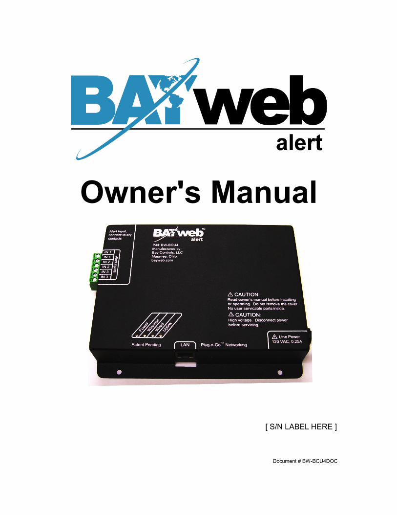
Owner's Manual
[ S/N LABEL HERE ]
Document # BW-BCU4DOC

BAYweb Alert Model BW-BCU4 Owner's ManualCopyright © 2009-2010 Bay Controls, LLCPart Number: BW-BCU4DOCRevision: 1.0 February 10, 2010
BAYweb is a registered trademarks of Bay Controls, LLC.Patent pending technologies are used in the BAYweb Alert.

Table of ContentsIntroduction.............................................................................................................1About This Manual..................................................................................................1
Safety Precautions..............................................................................................1Labels.................................................................................................................2Limited Warranty.................................................................................................3Limitation on Liability..........................................................................................3Unauthorized Repair...........................................................................................3
BAYweb Alert..........................................................................................................4Installation...............................................................................................................5
Overview.............................................................................................................5Install Control Module.........................................................................................6Install Sensors....................................................................................................7Wireless Sensors................................................................................................7Hard Wired Sensors...........................................................................................7Connect to the Internet.......................................................................................8Configuration....................................................................................................10Testing...............................................................................................................11
Operation...............................................................................................................11Web Portal........................................................................................................11Using Your Mobile Phone..................................................................................11
Reference..............................................................................................................12Control Module.................................................................................................12
Alert Inputs...................................................................................................12LAN Port.......................................................................................................12Line Power....................................................................................................13
Troubleshooting................................................................................................13Solutions to Problems..................................................................................13Obtaining Support........................................................................................15
Specifications........................................................................................................16

IntroductionThank you for purchasing the BAYweb Alert. You now have one of the most advanced web alerting systems available today.
This alert is easily installed by home owners or an electrician.
This model of BAYweb Alert (BW-BCU4) supports up to 8 wireless and up to 3 hard wired inputs with up to a total of eight zones.
About This ManualThis manual contains the information necessary for installing and operating the BAYweb Alert system. However, since installations may vary, these instructions may not cover all details or variations in the equipment supplied or every question that may possibly arise during use.
If a question or situation develops which is not answered directly in this manual, contact BAYweb support for specific answers and advice.
You should become familiar with the contents of this manual before the BAYweb Alert is put into service. This is particularly important with regard to the safety precautions listed in the Introduction section, and those included at relevant points in other sections of this manual.
Note that this manual is updated periodically. You can download the latest version at www.bayweb.com.
CAUTION: Read, be sure to clearly understand, and then carefully follow all of the directions and procedures included in this manual. Failure to adhere to the guidelines and specific instructions provided could cause equipment damage and serious personal injury or death.
Safety PrecautionsLow voltage control signals do not normally represent an electric shock hazard unless used in an environment for which the equipment was not designed for, such as a wet location.
The Web Alert is independently powered from a line cord connected to a standard 120 VAC electrical outlet. This line voltage does represent an electrical shock hazard if improperly used. Do not cut or modify the line cord in any way. Do not use a damaged line cord. Do not remove the cover of the control module. Do not expose the control module to water. Do not plug in the control module when wet.
Bay Controls, LLC. expressly disclaims responsibility or liability for any injury or damage caused by failure to observe specified or other common safety precautions or failure to exercise ordinary caution, common sense, and due care required in installing and operating the device even though not specified herein.
1
!

The alert message shown here appears throughout this manual to indicate those situations and times when special care is necessary to prevent equipment damage or personal injury.
CAUTION: This indicates that there could be the possibility of equipment damage or personal injury.
CAUTION: If this equipment is used in a manner not specified by Bay Controls, LLC., there may be a risk of equipment damage, serious personal injury, or death.
LabelsThe following safety labels alerts the installer or operator to possible hazards and serves to remind the user of specific safety precautions. Before installing and/or operating this device, be certain to review the pertinent safety labels.
CAUTION: Read owner's manual before installing or operating. Do not remove the cover. No user serviceable parts inside.
CAUTION: High – Voltage Disconnect power before servicing.
Line Power 120 VAC, 0.25 A
2
!
!
!
!
!

Limited WarrantySubject to the limitations contained below, and except as otherwise expressly provided herein, Seller warrants to the Buyer that all tangible articles supplied by Seller or services provided by Seller will be free of defects in materials or workmanship under normal use and care until the expiration of the applicable warranty period. Goods are warranted for five (5) years from the date of purchase. If Buyer discovers any defects and notifies Seller thereof in writing during the applicable warranty period, Seller shall at its option promptly correct, repair, or replace F.O.B. point of manufacture that portion of the good found by Seller to be defective, or refund the purchase price of the defective portion of the goods/services. All replacements or repairs necessitated by inadequate maintenance, normal wear and usage, unsuitable power sources, unsuitable environmental conditions, accident, misuse, improper installation, modification, repair, storage or handling, or any other cause not the fault of Seller are not covered by this limited warranty, and shall be at Buyer’s expense. Seller shall not be obligated to pay any costs or charges incurred by Buyer except as may be agreed upon in writing in advance by an authorized Seller representative. Goods repaired and parts replaced during the warranty period shall be in warranty for the remainder of the original warranty period or ninety (90) days, whichever is longer.
THERE ARE NO REPRESENTATIONS OR WARRANTIES OF ANY KIND, EXPRESS OR IMPLIED, AS TO MERCHANTABILITY, FITNESS FOR PARTICULAR PURPOSE, OR ANY OTHER MATTER WITH RESPECT TO ANY GOODS OR SERVICES.
Limitation on LiabilityTHE SOLE AND EXCLUSIVE REMEDY FOR BREACH OF WARRANTY HEREUNDER SHALL BE LIMITED TO REPAIR, CORRECTION, REPLACEMENT OR REFUND OF PURCHASE PRICE AS PROVIDED UNDER THE FOREGOING LIMITED WARRANTY. IN NO EVENT, REGARDLESS OF THE FORM OF THE CLAIM OR CAUSE OF ACTION (WHETHER BASED IN CONTRACT, INFRINGEMENT, NEGLIGENCE, STRICT LIABILITY, TORT OR OTHERWISE), SHALL SELLER’S LIABILITY TO BUYER AND/OR ITS CUSTOMERS EXCEED THE PRICE TO THE BUYER OF THE SPECIFIC GOODS SUPPLIED OR SERVICES PROVIDED BY SELLER GIVING RISE TO THE CLAIM OR CAUSE OF ACTION.
BUYER AGREES THAT IN NO EVENT SHALL SELLER’S LIABILITY TO BUYER AND/OR ITS CUSTOMERS INCLUDE “CONSEQUENTIAL DAMAGES”. FOR THIS PURPOSE, “CONSEQUENTIAL DAMAGES” SHALL INCLUDE, BUT NOT BE LIMITED TO, LOSS OF ANTICIPATED PROFITS, LOSS OF USE, LOSS OF REVENUE AND LOSS OF CAPITAL.
Unauthorized RepairIn the event that the owner allows the Web Alert to be serviced or repaired by unauthorized personnel, the coverage of the original warranty policy will be automatically terminated.
3

BAYweb Alert
The BAYweb Alert device can be used as self monitored security system.
It provides alert notification of up to 8 different zones via email and/or text enabled mobile phone.
Each alert zone will send notification messages to a list of one or more recipients. ®
Alert Sensing
The BAYweb alert device utilizes 3 wired inputs and an unlimited number of X10 wireless sensors.
There are 8 different zones which are configured to trigger an alert by sensing a signal on one or more of the wired inputs, or from an X10 wireless channel.
The wired inputs can use sensors that use either normally open, or normally closed contacts. When wired in series, up to 16 sensors can be used on a single input channel. The wired inputs are typically used for smoke alarms or other sensors that also require power to operate. These inputs are also ideal to use when retrofitting an existing alarm system.
The wireless X10 inputs support an unlimited number of sensors programmed with the X10 house/unit ID for a given zone. Wireless X10 occupancy sensors are economical and effective for sensing intrusions.
The alert server in our data center will alert you if the Internet connection used by the device goes offline for more than 10 minutes. This warns you that you will not receive other alerts until the Internet connection is restored.
Alert Handling
Upon sensing an alert condition, the alert device will immediately send a message to our data center, which in turn will send the alert message to the list of recipients configured for that zone.
Nominal response time for dispatching the notification message from our data center is 3 seconds. Delivery time of the message is dependent on your Internet or mobile provider.
Once an alert has been sent, it will not be sent again until a configurable time period has elapsed for that zone. An alert is also provided if the Internet connection goes down, and when it is restored.
The alert system can be armed or disarmed using the web and/or mobile portals.
4

Installation
OverviewInstalling the BAYweb Alert system is a relatively simple process and typically takes from 10 to 30 minutes to complete. You will need screwdrivers, a wire stripper/cutter, and a drill for installing the wall anchors to complete the installation. A volt/ohm meter can be helpful for troubleshooting but not required.
The control module may be mounted in a convenient location that allows easy access to Ethernet, AC power and hard wired sensor wiring.
You will need an Internet connection for the Control Module.
If it is not convenient to plug into your network there, consider using an optional power-line Ethernet adapter.
CAUTION: Be sure to review all of the installation steps before starting your installation.
5
!

1 Install Control ModuleA) Mount the Control Module using the following criteria:
◦ Select a location with easy access to hard wired sensor cables.
◦ Select a location within 6 feet of a power outlet, ideally on the same circuit as the furnace/AC.
◦ Select a location where you can connect to the Internet. If wiring is not convenient, we suggest using a power line Ethernet adapter that will allow you to make this connection using your existing power wiring.
B) Mount the BAYweb Alert module with the provided wall anchors and screws.
6

2 Install SensorsThere is a wide variety of additional sensors and devices that can be integrated into the alerting system. Refer to the device instructions for detail on installing those devices.
Wireless SensorsBAYweb Alert can use wireless (X10 wireless protocol) motion sensors. Bay sells a low cost wireless occupancy sensor that is ready to use with the BAYweb Alert. Just put in a couple of batteries and mount it in a location that typically sees activity when you are home. You can use as many sensors as needed enabling BAYweb Alert to monitor multiple locations in your home for occupancy.
The sensors from Bay have a 10+ foot sensing range and will sense people as they pass in front of the sensor. We have found that locating them at about chest height or higher works well.
Hard Wired Sensors
The BAYweb Alert hard wired inputs may only be connected sensors that provide dry contacts, this means no power is supplied by the sensor. The contacts must be rated for at least 12 VDC and 10 mA (0.01 Amps).
CAUTION: Do not connect the Alert input to any external voltage source. Dry contacts only. Failure to do so may cause equipment damage.
The two wires from the contacts of the sensor should be connected to the desired input. Polarity does not matter.Please refer to the instructions supplied with the sensor for mounting and wiring options.
7
!
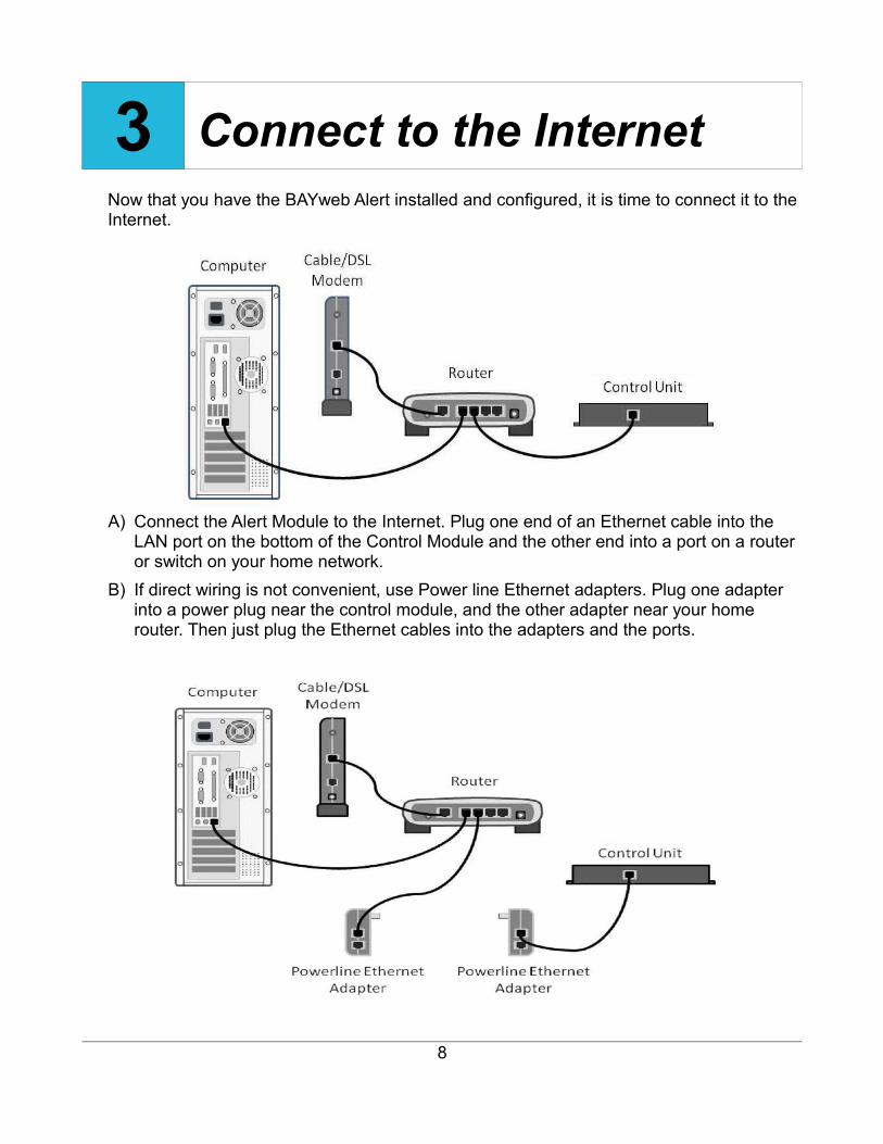
3 Connect to the InternetNow that you have the BAYweb Alert installed and configured, it is time to connect it to the Internet.
A) Connect the Alert Module to the Internet. Plug one end of an Ethernet cable into the LAN port on the bottom of the Control Module and the other end into a port on a router or switch on your home network.
B) If direct wiring is not convenient, use Power line Ethernet adapters. Plug one adapter into a power plug near the control module, and the other adapter near your home router. Then just plug the Ethernet cables into the adapters and the ports.
8

C) The BAYweb Alert does not require any configuration or programming of your networking equipment. You do not need to change security settings. Just plug it in and you are all set to go.
D) Plug the BAYweb Alert module into the power outlet.E) Verify that the “Power” light illuminates. F) In less than a minute the “Uplink” light should illuminate on the module. If it does, your
BAYweb Alert is on line and ready to go. If you do not see “Uplink” light up within a couple of minutes, refer to the Troubleshooting section of this manual.
9

4 ConfigurationUse the BAYweb Portal to access and configure your module. This portal can be accessed anytime from anywhere via web browser and Internet enabled mobile phone. Unlimited use of the portal is included at no charge.
To setup your personalized portal go to the web site (www.bayweb.com), register a new account, login and add a device (your BAYweb Alert module). You will need the serial number and key code that are on the front of this manual.
Once you have installed your equipment login to the web portal to configure them. To enable sensing select the “Settings” page from the Alert Applet menu and go to the Alerting Settings section. Configure the maximum alert frequency. This limits how often alerts will be sent if there are repeated signals. You can adjust this value later if needed to suit your lifestyle.
Each zone may be given a name of up to 16 characters. This name will be in the text messages that are sent for alerting.
Next you must configure your zones on the Alert Source Settings section. For each zone, define the wireless and wired inputs to use. Select the House/Unit code to enable wireless sensors or set House Code to NONE. For each zone, define which hardware inputs, if any will be used. The choices for hard wired inputs are:
OFF Disable input for that zone.N.C. Normally closed – Contact open for alarm condition.N.O. Normally open – Contact closed for alarm condition.
After configuring sensing review your schedule and set your “Home”, “Sleep” , and “Away” times as described above.
10

5 TestingA) Make sure that the BAYweb Alert is connected to the Internet and powered on.
CAUTION: To reduce the risk of electric shock, this product has a grounding type plug that has a third (grounding) pin. This plug will only fit into a grounding type power outlet. If the plug does not fit into the outlet, contact a qualified electrician to install the proper outlet. Do not change the plug in any way.
B) Verify that the “Power” light is illuminated on the control module. C) Verify that the Uplink light is on. This indicates that the module is communicating with
the BAYweb servers. D) Force each zone into the alarm state one at a time and verify that the zone indicates
the Alarm on the Alerting Applet. Please allow time for the status to be sent to the BAYweb center and time for your browser to refresh. This could take up to 30 seconds.
Operation
Web PortalUse the BAYweb Portal to access and configure your module. This portal can be accessed anytime from anywhere via web browser and Internet enabled mobile phone. Unlimited use of the portal is included at no charge.
Using Your Mobile PhoneOnce you have setup your personalized web portal, you can also use most any mobile phone that has web access to remotely access your device and other web devices. To access the mobile web portal, enter the following address in your mobile phone browser: www.bayweb.com/mobile.
11
!

Reference
Control Module
Alert InputsThese inputs can be used to connect to a variety of wired sensors, such as a sump pump monitor or alarm door contacts. To use this feature, wire terminal 1 to one side of a set of dry contacts, and terminal 2 to the other side. The Settings page on the Web Portal is used to configure normally open or normally closed contacts.
CAUTION: Do not connect the Alert input to any external voltage source. Dry contacts only. Failure to do so may cause equipment damage.
LAN PortThe LAN port is a standard Ethernet interface (IEEE 802.3 compatible with 10/100/1000 Base-T networks). This port operates at 10 Mbps (10Base-T). There are 2 LED activity indicators built into the the connector. The green LED will be illuminated whenever there is a physical link to your network (plugged in). The amber LED is illuminated when there is activity on the port.
12
!

Line PowerThe line cord is used to power the BAYweb Alert. This is a standard 3 blade grounded plug. Ideally this should be powered from the same circuit as your furnace/AC.
CAUTION: To reduce the risk of electric shock, this product has a grounding type plug that has a third (grounding) pin. This plug will only fit into a grounding type power outlet. If the plug does not fit into the outlet, contact a qualified electrician to install the proper outlet. Do not change the plug in any way.
TroubleshootingWe encourage you to communicate any problems you have encountered to us, even if you are able to solve them on your own. We would also like to have any suggestions or comments about the installation procedure.The preferred method of communicating with us is via email. We use an automated tracking system to insure that we respond to your messages in the quickest possible time, and provide the shortest path to problem resolution. Our support email address is [email protected]. We also have an on line support page that you can use to send a message to our support staff. If you need to speak to a support Representative, refer to the Obtaining Support section of this manual for contact information.When contacting us for support, please provide your name, web portal user ID (if you have one), and your serial number. We may also request your key code to validate that you have a given piece of equipment. The serial number and key code are located on the front cover of this manual and on the Control Module.We suggest you review the Solutions to Problems section and check the support resources on www.bayweb.com which may provide you with a simple solution to the problem.
Solutions to ProblemsProblem SolutionNo Control Module power indication. ➢ Check for power at outlet.
➢ Unplug Alert input connector, if power light comes on there is a short or improper connection on one or both of these connections.
➢ Contact support for replacement Control Module.
DHCP light is not ON:
Your Internet router is not supplying a local address to use on your network (DHCP is inoperative).
➢ Try resetting or power cycling your Internet router.
13
!

Problem SolutionThe schedule is not changing at the correct time.
➢ Review the Settings page on the Alert applet and make sure the timezone is set correctly.
Wireless occupancy sensor not working. ➢ Verify the X10 ID settings – see the settings page on the Alert applet.
➢ Verify the X10 ID settings of the sensor, refer to the instructions provided with the sensor.
➢ Check that the➢ Wireless light on the Control Module
turns ON when the sensor is activated.➢ Try adjusting/moving the antenna wire.
Wired alert input not working. ➢ Verify the wired input settings – see the Settings page on the Alert applet.
Control module not connecting to Internet, Uplink light does not come on.
➢ Verify that the green LED on the LAN connector (on the side of the Control Module) is illuminated.
➢ Verify that the amber LED on the LAN connector is blinking.
➢ Plug a laptop or PC into the connection you are using for the BAYweb Alert and verify that you can browse the Internet.
14

Obtaining SupportCustomer support is handled on line 24 hours per day, 7 days a week. Before requesting support, please review the Frequently Asked Questions and other resources available at www.bayweb.com. When contacting us for support, please provide your name, web portal user ID (if you have one), and module serial number, located on the front cover of this manual and on the Control Module.
Support email: [email protected]
Bay Controls, LLC6528 Weatherfield CtMaumee, OH 43537419-891-4390 (Monday - Friday 8:00 AM – 5:00 PM EST)
15

SpecificationsPart Number: BW-BCU4Applications: Residential, commercialSchedule: 7 day, up to 48 periods per dayClock: Synchronized with NIST atomic clock (± 1 sec) Memory: All settings and data maintained in non-volatile memory
indefinitely Alert Inputs: Unlimited X10 wireless and (3) wired dry contact inputsShipping Temperature Range: -40° to 150° FOperating Temperature Range: 0° to 120°Operating Relative Humidity: 5% to 90% (non-condensing)Power Method: Independently powered, line cordPower Requirements: 120 VAC, 60 Hz, 0.25 Amp maximumControl Electrical Rating: Class 2, 20 – 30 VAC 3.2 Amp maximumDimensions: Control Module: 6.85” W x 4.85” H x 1.3” DWeight: Control Module: 8 oz
16