Embed Size (px)
Citation preview

Owner’s Manual©2008-2013
Manufactured by:HELLENBRAND, INC.
404 Moravian Valley RoadWaunakee, Wisconsin 53597
Phone: 608-849-3050 • Fax 608-849-7398Web: www.hellenbrand.com • Email: [email protected]
Water Management System - Patent Pending

2
This owner’s manual is designed to assist owners and installers with the operation, maintenance and installation of your new water softener. It is our sincere hope that this manual is clear, concise and helpful to both owner and installer. We have included detailed in-structions on general operating conditions, pre-installation and installation instructions, start-up, and timer and meter programming. We have included a troubleshooting guide, service instructions and parts diagrams to assist you. Owners will appreciate the simplified, illustrated format for operation, programming and troubleshooting. In the event that you need professional assistance for servicing your water softener, please contact the dealer who installed this system.
Table Of COnTenTsJob Specification Sheet ...........................................................................................................................................................................3Soft Water Basics ....................................................................................................................................................................................4Operating Conditions ...............................................................................................................................................................................4 Pre-Installation Check List .......................................................................................................................................................................5Bypass Valve Operation ..........................................................................................................................................................................5Installation Instructions ............................................................................................................................................................................6Programming ...........................................................................................................................................................................................7Installer Programming .............................................................................................................................................................................8Softener Set-Up ..................................................................................................................................................................................9-12Service Reminder ..................................................................................................................................................................................13Diagnostics .......................................................................................................................................................................................13-14Valve History ..........................................................................................................................................................................................14Cycle Sequence ...............................................................................................................................................................................15-19Water Softener Disinfection ...................................................................................................................................................................20Water Softener Draining Procedure ......................................................................................................................................................20Troubleshooting ................................................................................................................................................................................21-23Parts Diagrams .................................................................................................................................................................................24-30Specifications ........................................................................................................................................................................................31Injector Flow Graphs ........................................................................................................................................................................31-32Programing Options and General Specifications...................................................................................................................................33Warranty ................................................................................................................................................................................................34

3
JOb speCifiCaTiOn sheeTMODEL NO. __________________________________________________________________________________________
*WATER TEST AT TIME OF INSTALLATION
_______ Hardness CaCo3 (gpg) ______ Other_____________________________ Iron (ppm) ______ Other_____________________________ pH ______ Other______________________
OPTIONAL RELAY SETTINGS ALT MAV AUX MAV_______ Off ______ Alternator system enabled ______ Brine Reclaim Enabled ______ Reclamation mode enabled ______ Separate Source Enabled ______ No Hard By-pass enabled ______ Separate Source enabled ______ System Board
Relay 1 Trigger _______ On Time _______Start Time, Minutes into Regeneration _______Run Time
_______ On Gallons Pulse per _______ Gallons _______ Time Relay Closed
_______ On Regen Gallons (Relay activated by flow through meter during service & regeneration) Pulse per _______ Gallons _______ Time Relay Closed
_______ On Service Alarm _______Years _______Gallons
*SIZING INFORMATIONAll Water is Softened Except:_______ Rear Hose Bib _______ Front Hose Bib _______ Kitchen Cold _______ Toilets _______ All Cold_______ Other ________________________________________________________________________________________
The average family uses 75 gallons per person daily for all water uses in the home, about 50 gallons per person daily if soft water is not supplied to the toilets, and about 30 gallons per person daily if only hot water is softened.
_______ Daily Water Usage (Gallons/Person)x _______ Family Size (Number of people in family)= _______ Total Gallons Per Dayx _______ Grains Per Gallon of Hardness (Note: Add 3 grains per gallon of hardness for each ppm iron for total compensated hardness)= _______ Total Grains Per Day
*INSTALLATION DATE _________________________________________________________________________________
*SERIAL NUMBER ____________________________________________________________________________________
NOTES ______________________________________________________________________________________________
Relay 2 Trigger _______ On Time _______Start Time, Minutes into Regeneration _______Run Time
_______ On Gallons Pulse per _______ Gallons _______ Time Relay Closed
_______ On Regen Gallons (Relay activated by flow through meter during service & regeneration) Pulse per _______ Gallons _______ Time Relay Closed
_______ On Service Alarm _______Years _______Gallons_______ Error

4
sOfT WaTer basiCshardnessExcess amounts of calcium and magnesium in water produce hardness. A water softener removes the majority of calcium and magnesium to produce softened water. Hardness is measured in terms of grains. (This grain weight is derived from the average weight of a dry grain of wheat.) When your water is tested the grain hardness is calculated and expressed as grains per gallon (gpg). This calculation, as well as the number of people in your household will help determine what type and size of water softener will most efficiently soften your water. Your water softener contains an ion exchange media (often called resin) which removes the hardness from water as it flows through the softener tank. Eventually so much hardness collects on the exchange media that the softener can no longer soften water. At this point it is considered "exhausted". Regeneration is now necessary.
regenerationTo regenerate the exchange media, it must be rinsed with a brine (salt) solution. This removes the hardness from the exchange media and replaces it with sodium. The exchange media is then ready to remove hardness from water. The hardness minerals and excess brine solution are rinsed down the drain. During the regeneration cycle the softening media is also backwashed. This reversing of the normal flow of water serves to remove sediment which may have accumulated during the softening process due to the filtering action of the exchange media. Backwashing also loosens and fluffs up the bed of exchange media to insure that during regeneration the brine solution will come into contact with all the media.
OperaTinG COnDiTiOns
Figure 1
Maintenance of Your softener Salt: Salt to a softener is what gasoline is to a car. Not only must a softener have salt, but it should be the proper type to insure efficient recharging of the unit. Ask your dealer what type of salt may best suit your needs. Always have an adequate supply of salt on hand. Check the salt level of your brine tank every couple of weeks initially to determine how much salt you use - this will depend on how much water you use. As a rule of thumb, with 20 gpg hard water, about a 1/2 lb. of salt per person per day is used. In other words, a family of four uses 60 lbs. of salt a month. Fill the tank approximately three-fourths full, with a minimum of 12” of salt. If your household does not use much water, do not fill your salt keeper over 1/2 full, salt bridging may occur in the brine tank. This may result in hard water due to ineffective regeneration. DO NOT USE Block Salt when the ProMate control is programmed with a brine tank prefill. Block salt does not dissolve quickly enough to provide a good regeneration. Cleaning Salt Tank: The salt tank may require periodic cleaning. Inspect the salt tank at least once a year for buildup of insoluble materials. It is recommended to periodically clean the salt tank no matter what kind of salt you are using. See page 19, Miscellaneous #2 for details on cleaning.
REMEMBER: Salt is the fuel to run your water softener. Buy the best clean salt available.
Your water conditioner has been designed to adequately handle up to 100 grains per gallon of hardness as well as up to 2 ppm of ferrous bicarbonate iron. This is iron that is dissolved in water and not visible to the eye in a freshly drawn sample. Upon standing in contact with air, the ferrous iron will become oxidized to the ferric state and start to precipitate as a reddish brown floc. It can be seen and may cause discolored water. In order for your softener to remove the iron, air (oxygen) must be kept from coming in contact with water until after it has been
passed through the water conditioner. In some cases, additional equipment may be required to treat water supplies having special characteristics, such as: ferric hydroxide iron, iron bacteria, low pH, taste and odors, etc. If any question should exist, contact your dealer.
This water softener is not intended to be used for treating water that is microbiologically unsafe or of unknown quality without adequate disinfection before or after treatment.

5
Water Pressure: A minimum of 25 pounds of water pressure (psi) is required for regeneration. Maximum 125 psi.Water Quality: On rural water supplies there is often a problem with sand or sediment in the water. (This problem occasionally occurs in public water supplies.) If the water is not filtered before being softened, the sand and sediment may plug up the water softener restricting the flow through the resin bed. This problem often requires rebedding of the mineral tank. Note: Well and/or pump problems affecting the operation of the softener are repairs that are not covered under warranty. To prevent these unneces-sary, and expensive repairs that are not covered under warranty, we recommend the installation of an in-line filter system ahead of a water softener.Electrical: A continuous 110 volt 60 cycle current supply is required. Make certain the current supply is uninterrupted and cannot be turned off with another switch. All electrical connec-tions must be connected per local codes. Surge protection is recommended with all electric controls.Existing Plumbing: Condition of existing plumbing must be free from lime and iron build-up. Piping that is built-up heavily
with lime and/or iron must be replaced. If piping is blocked with iron, additional equipment must be installed ahead of the water conditioner to correct the problem.Drain Line: The softener should be located close to a drain. Avoid overhead drain lines if possible to prevent back pressure on the brine injector. Overhead drains are not to exceed 8 feet above the floor and no more than 20 feet in length. The pipe size for the drain line should be a minimum of 3/4”. Backwash flow rates in excess of 7 gpm or length in excess of 20’ require 1” drain line.Bypass Valves: Always provide for the installation of a bypass valve. Softening: It is recommended that the conditioner be installed to soften both the hot and cold water supply. A separate hard water faucet may be plumbed for drinking purposes if desired. Outside faucets should be left on hard water.Caution: Water temperature is not to exceed 110°F; the condi-tioner cannot be subject to freezing conditions, or to a vacuum due to loss of pressure (such as a water main break).
pre-insTallaTiOn CheCk lisT
Figure 5Figure 4
(All electrical & plumbing should be done in accordance to all local codes)
Figure 2 Figure 3
bYpass valve OperaTiOn

6
CAUTION:• Do not use vaseline, oils or other hydrocarbon lubricants or
spray silicone anywhere. A silicon lubricant may be used on black o-rings but is not necessary. Avoid any type of lubricants, including silicone, on red or clear lip seals.
• Do not use pipe dope or other sealants on threads. Only teflon tape may be used on threads. Teflon tape is not necessary on the nut connection or caps because of o-ring seals.
• The pipe size for the drain line should be a minimum of 3/4”. Backwash flow rates in excess of 7 gpm or length in excess of 20’ require 1” drain line.
1. Place the conditioner where you want to install it, making sure it is on a clean, level and firm base.
2. Do all necessary plumbing (inlet to inlet, outlet to outlet and drain line to drain). The control valve, fittings and/or bypass are designed to accommodate minor plumbing misalignments but are not designed to support the weight of a system or the plumbing.
3. When assembling the installation fitting package (inlet and outlet), connect the fitting to the plumbing system first and then attach the nut, split ring and o-ring. Heat from soldering or solvent cements may damage the nut, split ring or o-ring. Solder joints should be cool and solvent cements should be set before installing the nut, split ring and o-ring. Avoid getting primer and solvent cement on any part of the o-rings, split rings, bypass valve or control valve.
4. A jumper ground wire should be installed between the inlet and outlet pipe whenever the metallic continuity of a water distribution piping system is interrupted. Install grounding strap on metal pipes.
5. The drain connection may be made using either 5/8” polytube (See figure 6a, page 6) or a 3/4” female adapter. If solder-ing, joints near the drain must be done prior to connecting the drain line flow control fitting. Leave at least 6” between the drain line control fitting and solder joints when solder-ing pipes that are connected on the drain line control fitting. Failure to do this could cause interior damage to the drain line flow control fitting.
6. The brine refill flow control assembly is installed in an easy to access refill elbow located on top of the control valve. The refill flow control assembly is attached to the control valve with a locking clip. The locking clip allows the elbow to rotate 270 degrees so the outlet can be orientated towards the salt tank.
7. Connect the brine line found in the brine tank to the brine connection on the control valve. The control valve has a standard refill elbow to which a 3/8” flexible tube can be connected, see figure 6a, page 6. (An optional elbow can be ordered which accommodates a 1/2” flexible tube for a high regenerant draw rate situation). Both elbows use the same refill flow control and retainer. Make sure the floor is clean beneath the salt tank and that it is level and smooth.
8. A 1/2” (inside diameter) gravity drain line may be connected to the overflow fitting on the side of the brine tank. This overflow is in case of a malfunction in the brine shut off. If the unit is installed where water may flow in the event of an overflow and cause water damage, connect a length of flexible tubing and run to a drain below the level of the overflow. (Do not connect the tubing to the drain line on the control valve. Do not run tubing above overflow height at any point.)
insTallaTiOn insTruCTiOns(All electrical & plumbing should be done in accordance to all local codes)
Figure 6a
Drain ConnectionBrine Line
Connection
Figure 6b

7
prOGraMMinG
initial start upThe initial start up will probably be done by the technician install-ing the softener system. If not, the following instructions will step you through the process.
1. Complete all plumbing connections: inlet, outlet, drain line and brine line. Do not add salt at this time.
2. Place the bypass valve in the bypass position. (See figure 3 page 6) Turn on the main water supply. Open a cold soft water faucet to flush the piping of any air and/or foreign material. Run until the water is clear.
3. Manually add 6 inches of water to the brine tank.4. Now plug the transformer into a 110-volt receptacle. (Be
certain the outlet is uninterrupted.) Within 5 seconds the control will automatically align itself into the softening mode and display will automatically alternate between time of day, gal/min and gallons remaining. (Figure 8, page 7).
5. Set the time of day by pushing clock button (figure 9, page 8) and using and buttons.
6. Push REGEN button and hold it down for 3 seconds. The system will advance to the “First” position. (Note: Depending on how the system is programmed it could read backwash, rinse, brine or fill). Pushing REGEN button until “Rinse” shows in the left upper hand corner of display. Slowly place the bypass into the “diagnostic mode” (see fig 4, page 5). Run water to the drain until it runs clear. Return the bypass valve to the by-pass position (fig 3, page 5). Push REGEN button until unit is back to softening mode.
7. Once again, push REGEN button and hold down for 3 seconds. Keep pressing REGEN button until “Back-
wash” appears. Slowly place the bypass valve into the “Diagnostic Mode” 1/2 way. Allow water to slowly fill the mineral tank. When a solid stream of water starts coming out of the drain line, open the bypass inlet valve all the way and allow to run out the drain until water clears. Then slowly place the by-pass into the “normal operation” mode by opening the outlet side of bypass valve, figure 2, page 5.
8. Press the REGEN button until LED display says “RE-GENERANT DRAW DN”. Loosen the brine line from the elbow on control valve in the brine tank. Place finger over the end of the elbow to check for suction. If no suction, see trouble-shooting guide. (See #10, Page 21) If proper suction, reattach brine tube and allow it to draw water down to the bottom of the air check, (figure 6b, page 6).
9. Press REGEN button again until LED once again dis-plays “BACKWASH”. Keep in backwash until water once again runs clear at the drain.
10. Press REGEN button again until “RINSE” is displayed. Allow rinse cycle to run its full course. While the rinse cycle is finishing, load brine tank with salt. If utilizing brine reclaim, manually add full volume of water to brine tank for first regeneration.
11. Once the rinse cycle has finished the softener control will return to the softening cycle. The LED screen will scroll between “TIME/GPM/GALLONS REMAINING”.
12. Next set your softeners water hardness, days override and regeneration time settings (see figure 10a, page 8).
Your programming is now complete.
General informationThe ProMate-6.0 control valve is the “brain” of your water soft-ener. It consists of the valve body and powerhead with solid state microprocessor. The display panel (see Figure 7) consists of the LCD display and five push buttons which are used in displaying and program-ming the water softener settings. Figure 7
user DisplaYs/seTTinGsGeneral OperationWhen the system is operating, one of several displays may be shown. Pressing NEXT will alternate between the displays. One of the displays is the current time of day. The second display is the following: days to a regen/gallons remaining. Days To A Regen is the number of days left before the system goes through a regeneration cycle. Capacity remaining is the number of gallons that will be treated before the system goes through a regeneration cycle. The third display is current flow in gal/min. The user can scroll between the displays as desired by pushing NEXT or display will scroll automatically.
When water is being treated (i.e. water is flowing through the system) the word "GPM" flashes on left side of display when other than flow rate is displayed.
Figure 8
DAYS TO A REGEN
6CAPACITY REMAINING
650REGEN TODAY
GAL
NORMAL OPERATION SCREENS
PM6:35TIME OF DAY
GPM6.8FLOW RATE
USER DISPLAY 1Typical user display. Shows capacity or days remaining before a regeneration.
USER DISPLAY 2Displays current time.
USER DISPLAY 3Displays present flow rate.
REGEN TODAYflashes in upper left corner of display between rotating dis-play when REGEN button pushed once.
GPMFlashes when the turbine is rotating.
User screens will continuously scroll, switching views every 3 seconds. If the screens are manu-ally scrolled, this screen will remain constant for 5 minutes then continue to scroll. The conditional screens will take precedence over the scrolling and the conditional conditions will apply.
To manually reduce capacity, press down button while capacity remaining or days to a regen is displayed.
DEALER NAMEDEALER PHONE NUMBER
12:00
GPM
May display if service is required.

8
= Up Arrow = Down Arrow
Step 1 - Press SET CLOCK.
Step 2 - Current Time (hour): Set the hour of the day using or buttons. AM/PM toggles after 12. Press NEXT to go to step 3.
Step 3 - Current Time (minutes): Set the minutes of day using or buttons. Press NEXT to exit Set Clock. Press REGEN to return to previous step.
Power Loss - Lithium battery on circuit board provides up to 2 years of time clock backup during power outages. If the power is out when battery is depleted, only time of day needs to be reset, all other values are stored in non-volatile memory. When time of day is flash-ing, replace lithium coin type 2032 battery.
Battery back-up feature will be activated after 24 hours of power.
Do not forget to reset for daylight savings time.
seT TiMe Of DaY
Figure 9
insTaller DisplaYs/seTTinGs
Step 1I - Press NEXT and simultaneously for 3 seconds.
Step 2I - Hardness: Set the amount of total compensated hardness in grains (hard-ness as calcium carbonate) per gallon using or buttons. The factory setting is 20 with value ranges from 1 to 150 in 1 grain increments. Note: The grains per gallon should be increased if soluble iron needs to be reduced. Add 3 grains of hardness for each ppm of iron present. If this display shows nA -, then system is set-up in “filter” mode or "AUTO" is not selected in softener system setup. (See page 32). Press NEXT to go to Step 3. Press REGEN to exit Installer Displays/Settings.
Step 3I - Day Override: This sets the number of days between regenerations. If value set to “oFF” regeneration initiation is based solely on gallons used. If value is set as a number (allowable range from 1 to 28) a regeneration initiation will be called for on that day even if sufficient number of gallons were not used to call for a regen-eration. Set Day Override using or buttons: Factory setting is 14 days.• number of days between regeneration (1 to 28); or• “oFF”
See pages 9-12, for more detail on softener setup. Press NEXT to go to step 4. Press REGEN to return to previous step.
Step 4I - Regeneration Time (hour): Set the hour of day for regeneration using or buttons. AM/PM toggles after 12. The factory setting time is 2:00 a.m. This display will show “REGEN” “IMMEDIATE ON zERO GAL” if “Immediate” is selected on Step 12 of softener set-up. See page 32. Press NEXT to go to step 5. Press REGEN to return to previous step.
Note: When installing this unit as part of a multi unit parallel system the regen time of day must be adjusted to prevent multiple units from regenerating at the same time.
Step 5I - Regeneration Time (minutes): Set the minutes of day for regeneration using or buttons. This display will not be shown if system is set for immediate regeneration. Press NEXT to exit Installer Displays/Settings. Press REGEN to return to previous step.
Figure 10a
RETURN TO ROTATING DISPLAY
Step 1
Step 2SET TIME 6:35PM
SET TIME 6:35PM Step 3
Step 1I
Step 2IWATER HARDNESS
Step 3IDAYS BETWEEN REGEN
14
Step 4IREGEN TIME HOUR
2:00AM
20
Step 5IREGEN TIME MINUTES
2:00AM
= Up Arrow = Down Arrow
SET GR
SET
SET
SET
SET
RETURN TO ROTATING DISPLAY

9
Manual regenerationSometimes there is a need to regenerate the system sooner than when the system calls for it, usually referred to as manual regeneration. There may be a period of heavy water usage because of guests or a heavy laundry day.
To initiate a manual regeneration at the preset delayed regeneration time, press and release “REGEN”. The words “REGEN TODAY” will flash in left corner of display as it scrolls through displays to indicate that the system will regenerate at the preset delayed regeneration time. If you pressed the “REGEN” button in error, pressing the button again will cancel the request.
To initiate a manual regeneration immediately, press and hold the “REGEN” button for five seconds. The system will begin to regen-erate immediately. The request cannot be cancelled. You must cycle all the way through the cycles to make it stop. PLEASE NOTE: This will reset the meter. Note: If the salt tank does not contain salt, fill with salt and wait at least two hours before regenerating. If two regenerations are desired within 24 hour period, press /release REGEN button. REGEN TODAY will flash on screen. Press and hold REGEN button until valve initiates regeneration.
Figure 11
CYCle TiMe aDJusTMenTsNormally it is not recommended to adjust the lengths of the cycle times. However, certain water conditions may dictate adjustments. This should only be done from the recommendation of a water conditioning professional. The following chart shows the upper and lower limits of each cycle.
Cycle Options Units Lower/Upper Limit Factory SettingFill Lbs. 0.1 to 200 See Page 30Softening (Service) Minutes 1 to 480 120Backwash Minutes 1 to 120 8Regenerant Draw DN Minutes 1 to 180 60Rinse-Fast Minutes 1 to 120 4
"REGEN TODAY"
320CAPACITY REMAINING
GAL
Regeneration Step(shows time remaining in regen step
is 8 minutes, 22 seconds)
BACKWASH
8:22
Regeneration ModeTypically a system is set to regenerate at a time of low water usage. An example of a time with low water usage is when the household is asleep. If there is a demand for water when the system is regenerating, untreated water will be supplied.
When the system begins to regenerate, the display will change to include information about the step of the regeneration process and the time remaining for that step to be completed (see figure 11). The system runs through the steps automatically and will reset itself to provide treated water when the regeneration has been completed.
Step 1S
Step 2S SOFTENING
Step 3SFILL
6.0
STEP 1S – Press NEXT and simultaneously for 3 seconds. If screen in Step 2S does not appear in 5 seconds the lock on the valve is activated.
STEP 2S – Select between softening or filtering. A flashing "SOFTENING" or "FILTERING" will appear. Choose SOFTENING using or button. Factory setting is Softening. Press NEXT to go to Step 3S. Press REGEN to exit Softener System Setup.
STEP 3S – Select the time for the first cycle (which in this example is FILL, setting is changed by lbs. of salt entered) using the or button. Factory setting is Low Salting, See page 30. Press NEXT to go to Step 4S. Press REGEN to return to previous step.
sOfTener seTup = Up Arrow = Down Arrow
SET
SET TYPE
LBS

10
STEP 4 S – Select the time for the second cycle (which in this example is SOFTENING) using or button. Press NEXT to go to Step 5S. Press REGEN to return to the previous step.
STEP 5 S – Select the time for the third cycle (which in this example is BACKWASH) using the or button. Press NEXT to go to Step 6S. Press REGEN to return to the previous step.
STEP 6 S – Select the time for the fourth cycle (which in this example is BRINE DRAW) using the or button. Press NEXT to go to Step 7S. Press REGEN to return to the previ-ous step.
STEP 7 S – Select the time for the fifth cycle (which in this example is SECOND BACK-WASH) using the or button. Press NEXT to go to Step 8S. Press REGEN to return to the previous step.
STEP 8 S – Select the time for the sixth cycle (which in this example is RINSE) using the or button. Press NEXT to go to Step 9S. Press REGEN to return to the previous step.
STEP 9 S - Set Grain Capacity using the or button. The ion exchange capacity is in grains of hardness as calcium carbonate for the system based on the pounds of salt that will be used. The allowable grains capacity range varies from 5,000 to 3,000,000 grains. The increment increase is 500 for the range from 5000 to 30,000; 1000 for the range of 30,000 to 100,000; and 2000 for the range of 100,000 to 3,000,000. Grains capacity is affected by the fill time. The grains capacity for the selected lbs. salting should be confirmed by testing. The capacity and hardness levels entered are used to automatically calculate reserve capacity when gallon capacity is set to AUTO. Factory setting is the capacity of the softener at low salting. See Page 30. Press NEXT to go to Step 10S. Press REGEN to return to previous step.
STEP 10 S – Select between proportional or normal brining. Use or buttons to select. Proportional brining is only available if configured as prefill/upflow softener or screen will not appear. Proportional brining will divide the actual gallons used by calcu-lated volumetric capacity then multiply fill volume by this percentage. This option requires a functioning meter. Factory Setting = Normal brining. Press NEXT to go to Step 11S. Press REGEN to return to previous step.
STEP 11 S – Set Gallons Capacity using or button. If value is set to:• “AUTO” gallon capacity will be automatically calculated and reserve capacity will be auto-matically estimated;• “oFF” regeneration will be based solely on the day override set (see Installer Display/Set-tings Step 3, page 9 / proportional brining will not function if OFF selected); or • as a number of gallons (allowable range 20 to 1,500,000) regeneration will be based on the value specified.Increment increase is 20 for the range 20 to 2000, 100 for the range of 2000 to 10,000 and 500 for the range of 10,000 to 50,000 and 2000 for range of 50,000 to 1,500,000.If “oFF” or a number is used, hardness cannot be set in Installer Displays/Settings Step 2, page 9. See page 32 for more detail. Factory Setting is AUTO. Press NEXT to go to Step 12 S. Press REGEN to return to previous step.
Figure 12a
Step 4SSOFTENING TIME
120:00MIN
Step 5S
SET 8:00MIN
BACKWASH TIME
Step 6S
SET 60:00MIN
DRAW TIME
Step 7S
SET
BACKWASH TIME
Step 8SRINSE TIME
Step 9SGRAIN OF CAPACITY
22.9
x1K
Step 11SRESERVE CALCULATOR
AUTO
SET
Step 10SSET
NORMAL
SET
8:00
SET
MIN
4:00SET MIN
FILL

11
STEP 12 S – Set Regeneration Time Options using the or button. If value is set to:• “DELAY” means regeneration will occur at the preset time; (page 8, step 4)• “IMMEDIATE” means regeneration will occur immediately when the gallons capacity reaches 0 (zero); or• “DELAY + IMMEDIATE” means regeneration will occur at one of the following:- the preset time when the gallons capacity falls below the reserve or the specified number of days between regenerations is reached, whichever comes first; or- immediately after 10 minutes of no water usage when the gallon capacity reaches 0 (zero).-Delay + Immediate is NOT available if control is programmed as a twin alternating configuration. Selecting "DELAY" will result in an immediate alternation upon capacity depletion but regeneration is delayed to preset time.See page 32 for more options. Factory Setting is DELAY + IMMEDIATE. Press NEXT to go to Step 13S. Press REGEN to return to previous step.
Step 12SDELAY + IMMEDIATE
REGEN
SET
RELAY 1 DURATION
Step 14SRELAY 1 SET POINT
10
MIN
RELAY 1 DURATION
3:00 MIN
Step 15S
RELAY 1 SETPOINT
GAL1
SET
Step 13SRELAY 1 "TIME"
TRIGGER
SET
SET
SET
SET 0:01 MIN
RELAY 1 "GALLONS"
TRIGGERSET
Step 16S
Step 18S
Step 17S
SET TRIGGER GAL
Step 19SRELAY 1 "REGEN GALLONS"
STEP 13 S – Set Relay to activate by Time, Gallons, Regen Gallons, Lockout, Off or Service Alarm by using or buttons. A relay can be used to operate a chemical feed pump or solenoid, etc. The choices are: • Relay Triggered on Time - Relay activates after set number of minutes after start
of regeneration. Start of regeneration is defined by first backwash cycle, dn brine or up brine, whichever is first. Relay deactivates after set time. Press NEXT for programming.
• Relay Triggered on Gallons - Relay activates every set number of gallons while in service and deactivates after set time. Press NEXT to go to 17S for programming.
• Relay Triggered on Regen Gallons - Relay activates after set number of gallons in service or gallons used during regeneration and de-activates after set time or when meter stops registering flow, whichever comes first. Press NEXT to go to 20S for programming.
• Service Alarm - Relay activates on service alarm setting: gallons, time or both, see step 22S.
• Relay Triggered for Lockout - Relay is activated at set number of minutes into regeneration including negative numbers to energize relay prior to regenera-tion starting. Selection of energizing relay for complete regeneration cycle is available by selecting REGEN for time setting, see step 23S.
• Off - If off is selected, Steps 14S – 22S will not be shown. Factory setting = OFF. Press NEXT to go to step 14S or other selection for relay settings, or 23S if OFF selected.
STEP 14 S – If off was selected in previous step, this screen does not appear. Time chosen to Activate Relay, use up and down arrows to set # of minutes AFTER START OF REGEN to activate relay. Start of regeneration is defined as first Backwash or Regenerant Draw mode. Time Range = 1 – 500 minutes. Press NEXT to go to Step 15S.
STEP 15 S – Use Up and Down arrows to set duration of relay activation in minutes. Range is 0:01 (1 second) to 500:00 (500 minutes). Press NEXT to go to Step 26S. Press REGEN to return to previous step.
STEP 16 S – Gallons chosen to activate relay. If Off or Time was selected in previous steps, this screen does not appear. Press NEXT for trigger programming.
STEP 17 S – Use up and down arrows to set # of gallons per relay activation. Range = 0.1 – 20,000 gallons. Press NEXT for Relay Duration. Press REGEN to return to previous step.
STEP 18 S – Use up and down arrows to set duration of relay activation in minutes. Range = 0:01 (1 second) - 500:00 (500 minutes). Press NEXT to go to Step 26S. Press REGEN to return to previous step.
STEP 19 S – REGEN gallons chosen to activate relay. Relay activates after set number of gallons have been used in service or during regeneration and then de-activates after set period of time or after flow stops, whichever comes first. Press NEXT to go to Step 20S.

12
RELAY 1 SET POINT
SET 1 GAL
STEP 20S – Use up and down arrows to select number of gallons per relay activation of regen gallon setting. Range: 0.1 -20,000 gallons. Press NEXT to go to Step 21S.
STEP 21S – If Off or Time was selected in previous steps, this screen does not appear. Use up and down arrows to set duration of relay activation in minutes. Range = 0:01 (1 second) - 500:00 (500 minutes). Press NEXT to go to Step 26S. Press REGEN to return to previous step.Meter does not read during regeneration.
STEP 22SService Alarm chosen to activate relay, relay closes whenever Service Alarm has triggered. Programming for relay closure on service reminder is done on Step 26S. Relay opens when service alarm reset. Press NEXT to go to Step 24S to set Relay 2 Settings. If off selected for Relay 2, service reminder programming on Step 26S.• Relay closes on Gallons• Relay closes on Time• Relay closes on Both• Off, Factory setting is off
STEP 23SRelay Triggered for Lockout, relay is activated for set number of minutes into regeneration including negative numbers to activate prior to regeneration starting. Press NEXT to Set Start Time.
STEP 24SUse up or down arrows to select minutes of relay activation. Range = -20 – 500 minutes. Press NEXT to select duration of relay activation. You may select REGEN if relay activation is desired for complete regeneration.
STEP 25SUse up or down arrows to select duration of relay activation. Range = 0:01 (1 second) - 500:00 (500 minutes). Press NEXT to go to Relay 2 programming.
Step 20S
RELAY 1 DURATION
SET 0:01 MINStep 21S
RELAY 1 SERV ALARM
SET TRIGGER Step 22S
RELAY 2 TRIGGER
SET REGEN GAL
Step 26S
RELAY 1 LOCKOUT
SET TRIGGER Step 23S
STEP 26S – Relay 2 programming includes identical options as Relay 1 with the addition of the ability to trigger Relay 2 in Error Mode. Relay closes when ever control enters Error Mode and immediately deactivates when error resolved and control reset. Press NEXT to go to Step 27S.
RELAY 1 SETPOINT
SET -20
Step 24S
MIN
RELAY 1 DURATION
SET 70:00 Step 25S
MIN
13
DiaGnOsTiCs
STEP 1D
= Up Arrow = Down Arrow
Reset Diagnostic Values: Hold NEXT/DOWN buttons for 3 seconds, then hold UP/DOWN buttons for 3 seconds.
STEP 2D2
DAYS SINCE REGEN
DAY
STEP 3D342
GALSINCE LAST REGEN
STEP 4D0 160
DAY
GALRESERVE HISTORY
serviCe reMinDerSTEP 27S – Set scheduled service display using or buttons. Available options are OFF, TIME, ON GAL or BOTH. Selecting OFF disables this feature. If OFF is selected, press NEXT to exit System Setup. If TIME, ON GAL or BOTH is selected press NEXT to select the TIME and/or ON GAL values. See Steps 28S and/or 29S. When days fall below 1 year, display shows "SCHED-ULED SERVICE in XXX DAYS", so service technician can reprogram if desired. This can also acti-vate relay if Service Alarm is selected on Step 22S. Press REGEN to return to the previous step.
STEP 28S – Service alarm for TIME ranges from 0.25 to 9.75 years. Press and buttons to-gether until "set" appears to select value. Press NEXT to either exit System Setup or if BOTH was selected go to Step 29S. Press REGEN to return to the previous step. When time selected and # of days drops below 1 year, the display in OEM program will show "scheduled service in XXX days" right after screen where service reminder is programmed.
STEP 29S – Service alarm for ON GAL ranges from 100 to 9,999,900 gallons. Press and buttons together until "set" appears, use arrows to select value. Press NEXT to exit System Setup. Press REGEN to return to the previous step.
Reset service reminder by pressing up and down arrows together when reminder is displayed.
SERVICE ALARM
SET BOTH Step 27S
SCHEDULED SERVICE
SET 0.25 Step 28S
YR
SCHEDULED SERVICE
SET 80000 Step 29S
GAL
RETURN TO NORMAL MODE
STEP 1D – Press or simultaneously for three seconds. If screen in step 2D does not appear in 5 seconds the lock on the valve is activated.
STEP 2D – Days, since last regeneration: This display shows the days since the last regenera-tion occurred. Press the NEXT button to go to Step 3D. Press REGEN to exit Diagnostics.
STEP 3D – Volume, since last regeneration: This display shows gallons of water that has been treated since the last regeneration. This display will equal zero if a water meter is not installed. Press the NEXT button to go to Step 4D. Press REGEN to return to previous step.
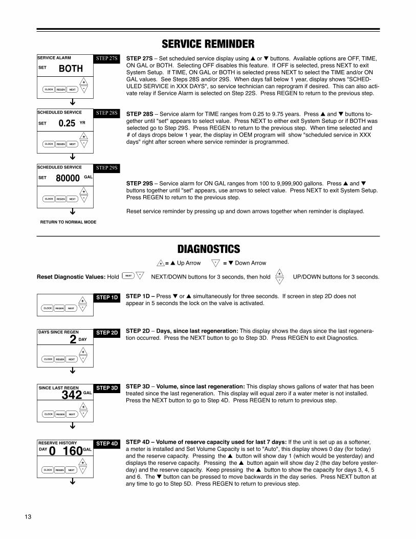
STEP 4D – Volume of reserve capacity used for last 7 days: If the unit is set up as a softener, a meter is installed and Set Volume Capacity is set to "Auto", this display shows 0 day (for today) and the reserve capacity. Pressing the button will show day 1 (which would be yesterday) and displays the reserve capacity. Pressing the button again will show day 2 (the day before yester-day) and the reserve capacity. Keep pressing the button to show the capacity for days 3, 4, 5 and 6. The button can be pressed to move backwards in the day series. Press NEXT button at any time to go to Step 5D. Press REGEN to return to previous step.

14
STEP 1VH – Press and simultaneously for three seconds and release, then press and simultaneously and release. If screen in step 2VH does not appear in 5 seconds the lock on the valve is activated.
STEP 2VH – Days, total since start-up: This display shows the total days since startup. Press the NEXT button to go to Step 3VH. Press REGEN to return to previous step.
STEP 3VH – Regenerations, total number since start-up: This display shows the total number of regenerations that have occurred since startup. Press the NEXT button to go to Step 4VH. Press REGEN to return to previous step.
STEP 4VH – Volume, total used since start-up: This display shows the total gallons treated since startup. This display will equal zero if a water meter is not installed. Press NEXT button to go to Step 5VH. Press REGEN to return to previous step.
STEP 5VH – Error Log history: up to 10 errors. Press and buttons to view each recorded error. If no errors have occurred " – – – –" is displayed. With STALL ERRORS 102, 107, 117. right upper corner of display indicates piston position at time of stall. Press NEXT to exit valve history.
STEP 1VH
valve hisTOrY
STEP 2VH970TOTAL DAYS
STEP 3VH235
STEP 4VH175
GALx1K
(Can not be reset)
TOTAL REGENS
TOTAL GALLONS
STEP 5VH1- - -
ERROR LOG
STEP 5D – Volume of water used, 63-day usage history: This display shows day 0 (for today) and 1 (for yesterday) will show day 2 (which would be the day before yesterday) and flashes the volume of water treated on that day. Continue to press the button to show the volume of water treated for the last 63 days. If a regeneration occurred on the day, the "letter R" will also be displayed. This display will show dashes if a water meter is not installed. Press the NEXT button at any time to go to Step 6D. Press REGEN to return to the previous step.
STEP 6D – Flow rate, maximum of each of last seven days: The maximum flow rate in gallons per minute that occurred in each of the last seven days will be displayed. Press arrow to dis-play maximum flow rate today = 0, yesterday = 1. This display will equal zero if a water meter is not installed. Resettable by pressing & arrows for 5 seconds. Press the NEXT button to exit Diagnostics. Press REGEN to return to the previous step.
STEP 7D – MAV Drive History – Not displayed if MAV set to off.• First - Average of 1st three drive times of MAV in that direction• Last - Last drive time measured for that MAV in that direction• Ave - Average drive time measured for MAV in that direction• TTT - Drive time (1424 = 14.24 seconds)• CCC - Total number of cycles for that MAV• VVV - Relative drive voltageMAV drives piston "in" is designated by (-) sign.MAV drives piston "out" is designated by (+) sign.
Any time MAV is rebuilt or replaced, reset diagnostics to reflect new drive characteristics.
STEP 6D12.7
GAL
MAX FLOWDAY 6
STEP 5D
USAGE HISTORY DAY 108 GAL
1
RETURN TO NORMAL MODE
Step 7D
CCC
TTT ALT + FIRSTCYC
VVV
XXXX

15
CYCle seQuenCeAnytime cycle sequence is modified, softener set-up will revert to manufacturer setting and must be reprogrammed as desired.
Cycle Sequence instructions allows the operator to set the order of the cycle. The Softener System Setup allows the operator to set how long the cycles will last. The operator may choose up to 9 cycles in any order.
END must be used as the last cycle option. The SERVICE cycle should only be used in brine prefill applications to allow salt to dissolve.
Cycle Options
BACKWASH FILL
RINSE SOFTENING END
The following is an example of how to set a valve so that when regeneration is initiated, BACKWASH occurs first, REGENERANT DRAW DN occurs second, RINSE occurs third, and FILL occurs fourth.
REGENERANT DRAW-DN
STEP 1CS – Press NEXT and simultaneously until TYPE appears on screen and release. Then press NEXT and simultaneously again for 3 seconds and release. If screen in step 2CS does not appear in 5 seconds the lock on the valve is activated.
STEP 2CS – Valve Type. Use the or to select from 1.0", 1.25", 1.50", 2.0L", 2.0" valve. ProMate-6.0 is a 1.0” meter. Press NEXT to go to Step 3CS.
STEP 1CS
STEP 2CS1.0SET
STEP 3CSOFFALTERNATOR SYSTEM
SET
VALVE TYPE
ALT AALTERNATOR SYSTEM
SET
STEP 4CS
STEP 5CSDELAYED RINSE & FILL
SET
OFF MIN
IN
STEP 3CS – Use the or to select one of the following:• Twin Alternating System – Select Alt A or Alt B, See instructions in Step 4CS; or• System Board - Allows Demand Recall Programming – See instructions in Step 10CS.• No Hard Water Bypass During Regeneration – See instructions in Step 7CS.• Reclaim Enabled - Allows control to operate in Reclamation Mode See instructions in Step 9CS.• Separate Source Enabled - Allows control to have a separate water source during the regeneration cycle. See instructions in Step 8CS.• OFF; Factory Setting is OFF - Press NEXT to go to Step 11CS.
STEP 4CS –Twin Alternating System – Allows automatic alternation between two units to provide softened water 24 hours a day.Use or buttons to select ALT A or ALT BSelect ALT A for the control valve that has the two-pin connector labeled MAV DRIVE connected to the alternator valve.Select ALT B for the control valve that will be connected via three-prong connector labeled INTERCONNECT. Must use 3-wire interconnect cable. Press NEXT to go to Step 5CS.For Alternating System, change programming:• Set softener, with volume capacity in GALLONS and select Regeneration Time Option
“IMMEDIATE” or "DELAYED" and select DAYS BETWEEN REGEN as desired.• For complete programming, see Twin Alternating MAV manual.
STEP 5CS – Select Twin Alternating Option.Use or buttons to select:• Standard - Standard Alternating Function• Refresh Rinse - Alternates every 6am & 6pm and runs programmable number of gallons
to service prior to alternating back to online unit. Press NEXT to set number of gallons.• Delayed Rinse and Fill- See below
This option delays the last two cycles of regeneration (only "Rinse" and "Fill"). This feature splits the regeneration into two portions. The first portion of the regeneration will start immediately and all programmed cycles before the "Rinse" and "Fill" cycles will be performed. After all programmed cycles before "Rinse" and "Fill" are completed the control valve will drive to the service position (displaying "Delayed Rinse + Fill Pend-ing"). When the volume of the on-line unit is depleted to 10% of its programmed capac-ity, the control valve will be triggered to finish the second portion of the regeneration and complete the "Rinse" and "Fill" cycles and return to Service and be placed into Standby mode, and wait to come on-line for service. Must be programmed for post brine fill. Press NEXT to go to Step 10CS.

16
STEP 6CS – No Hard Water Bypass Enabled - Selection requires that a connection to a Motorized Alternator Valve (MAV) is made to the two pin-connector labeled ALTERNATOR MAV DRIVE located on the printed circuit board. The MAV will be driven closed before the first regeneration cycle that is not FILL or SOFTENING or FILTERING, and be driven open after the last regeneration cycle that is not FILL. NOTE: If the control valve enters into an error state during regeneration mode, the no hard water bypass valve will remain in its current state until the error is corrected and reset. Press NEXT to go to Step 10CS.
STEP 7CS – Configuring the Control Valve for Separate Source Operation - Select Separate Source Enabled for control operation. For separate source operation, the three wire connector is not used. Selection requires that a connection to a MAV is made to the two pin connector labeled ALTERNATOR MAV DRIVE located on the print-ed circuit board. The C port of the MAV must be connected to the valve inlet and the A port connected to the separate source used during regeneration. The B port must be connected to the feed water supply. When set to Separate Source Enabled the MAV will be driven closed before the first regeneration cycle, and be driven to open after the last regeneration cycle.NOTE: If the control valve enters into an error state during regeneration mode, the MAV will remain in its current state until the error is corrected and reset. Press NEXT to go to Step 10CS.
ENABLEDNO HARD BYPASS
SET
STEP 6CS
SEPARATE SOURCE
SET
STEP 7CSENABLED
SYSTEM BOARD
SET STEP 9CSENABLED
STEP 9CS – Configuring the Control Valve to operate with the Hellenbrand System Con-troller - Select System Board Enabled to link the Control Valve to the SystemMate Controller. For communication between the Control Valve and the System Controller a three wire communi-cation cable is required.
Press NEXT to go to Step 10CS. Press REGEN to return to previous step.
STEP 8CS – Configuring the Control Valve for Water Reclamation Mode - Select Reclaim Enabled for control operation. Mo-torized Alternating Valve will advance to Bypass at a set time after the beginning of regeneration, and return to Service after a set duration. This allows water to be diverted from drain for reuse. Up to three bypass events are possible. Select reclaim enabled for 1 reclaim event, reclaim 2x for two reclaim events, reclaim 3x for three reclaim events.
The Alternating MAV transitions to Bypass at the set time after the start of regeneration. The start of regeneration is defined as the first cycle that is not FILL, SOFTENING or FILTERING. The Alternating MAV will transition back to Service after the completion of the preset duration time.
Page 10 HP Man ual
Confi guring the Control Valve to operate with Clack System Controller:Select System Board Enabled to link the Control Valve to the Clack System Controller. For communication between the Control Valve and the System Controller a three wire communication cable is required.Press NEXT to go to Step 5CS. Press REGEN to return to previous step.
Confi guring the Control Valve for Reclamation Mode:Select Reclaim Enabled for control operation. Motorized Alternating Valve will advance to Bypass at a set time after the beginning of regeneration, and return to Service after a set duration. Up to three bypass events are possible. From the SET screen, pressing SET CLOCK will increase the number of reclaim cycles up to 3.
From the RECLAIM ENABELD screen, pressing the SET CLOCK button will increase the number of reclamation cycles, up to 3. The Alternating MAV transitions to Bypass at a set time after the start of regeneration. The start of regeneration is defi ned as the fi rst cycle that is not FILL, SOFTENING or FILTERING. The Alternating MAV will transition back to Service after the completion of the presetduration time.
STEP 8CS
MAV RECLAIM DURATION MAV RECLAIM DURATION MAV RECLAIM DURATION

17
30:00AUX RECLAIM START
SET
MIN
STEP11CS
AUX RECLAIM DURATION
SET STEP 12CS6:00 MIN
STEP 11CS – Only displays if reclamation of brine is enabled in Step 11CS. Use the or buttons to select the number of minutes after the start of regeneration before the MAV will divert the brine waste water from the plumbing drain receptacle to the brine tank. Start of regeneration is defined as any mode that is not fill or softening. Use Table 1 on page 17 for settings.
Press NEXT to go to Step 12CS. Press REGEN to return to previous step.
STEP 12CS – Only displays if reclamation of brine is enabled in Step 11CS. Use the or buttons to select the number of minutes to divert the brine waste water to the brine tank. After the minutes count down to zero the waste water will once again be diverted to the plumbing drain receptacle.
Press NEXT to go to Step 13CS. Press REGEN to return to previous step.
STEP 10CS – Use the or buttons to select one of the following:• Reclaim – Allows brine reclaimation. Select Reclaim for 1 Reclaim Event, Reclaim 2x for 2 reclaim events and Reclaim 3x for 3 reclaim events – See instructions ON PAGE 18.• Separate Source –Allows Auxiliary MAV to switch positions before the start of regeneration and to switch back at the end of regeneration. See instructions in Step 13CS.• Off - Factory Setting is OffPress NEXT to go to Step 11CS when reclaim selected as trigger. Press REGEN to return to previous step.
TRIGGERAUX MAV OFF
SET
STEP 10CS
HP Manual Page 11
STEP 5CSStep 5CS – Set Auxiliary Drive Output (MAV only) to operate in one of three modes:• Set RECLAIM (Time): Allows Auxiliary MAV to switch positions at a set time in relation to the start of regeneration for a preset duration, independently of the actual regeneration status. Up to 3 bypass events are possible.• Set SEP SOURCE: Allows Auxiliary MAV to switch positions before the start of regeneration and then switch back at the end of regeneration.• Set OFF: Deactivates this output.
Only use Clack Motorized Alternating Valves (MAV) with these selections. Clack No Hard Water Bypass Valves (1” or 1.25” V3070FF or V3070FM) are not designed to be used with the reclaim or separate source functions.
Press NEXT to go to Step 6CS. Press REGEN to return to previous step.
AUX RECLAIM DURATION AUX RECLAIM DURATIONAUX RECLAIM DURATIONX

18
AUX MAV SEP SOURCE
SET
STEP 13CSTRIGGER
STEP 13CS – Separate source selection requires connection of motorized alternator valve (MAV) to Auxiliary Drive two-pin connection on board.
Auxiliary MAV Drive set to operate with a Separate Source trigger. Auxiliary MAV transitions to Bypass before the start of regen cycle #1, AFTER Alternator MAV motor transition. Auxiliary MAV transitions back to Service at the completion of the last programmed regen cycle, once the Valve Motor deactivates and BEFORE Alternator MAV transition (if scheduled). Auxiliary MAV will NOT automatically return to Service while manually stepping valve through regen, MAV will remain in Bypass until regen cycle end. Press NEXT to go to Step 14CS. Press REGEN to return to previous step.
STEP 14CS – This display will be available to select the use of an outside signal to control the initiation of a regeneration. Selection only matters if a connection is made to the two pin connec-tor labeled DP SWITCH located on the printed circuit board. Following is an explanation of the options:• IMMED REGEN – If the dP switch is closed for an accumulative time of 2 minutes, a regenera-tion will occur immediately.• DELAY REGEN – If the dP switch is closed for an accumulative time of 2 minutes, a regenera-tion will occur at the schedule regeneration time.• HOLD REGEN – If the dP switch is closed a regeneration will be prevented from occurring.• OFF - Factory setting is offPress NEXT to go to Step 15CS. Press REGEN to return to previous step.
OFFAUXILIARY INPUT
SET
REGSTEP 14CS
Table 1 – brine reClaiMstart time / stop = duration / salt setting - 10 lbs./ft3
Water Pressure PM6-24 PM6-32 PM6-32-10 PM6-48 PM6-64 35 PSI 46:00/9:40/1.5 48:00/10:00/2.0 48:00/10:00/2.0 48:00/12:00/3.3 54:00/11:00/4.2 45 PSI 42:00/7:45/1.5 44:00/8:45/2.0 44:00/8:45/2.0 46:00/11:00/3.3 52:00/11:00/4.3 55 PSI 39:00/7:20/1.5 41:00/8:30/2.0 41:00/8:30/2.0 44:00/11:00/3.3 49:00/8:30/4.0 65 PSI 38:00/6:40/1.5 40:00/7:45/2.0 40:00/7:45/2.0 43:00/9:45/3.0 48:00/7:40/4.0
start time / stop = duration / salt setting - 10 lbs./ft3 Water Pressure PM6-96 PM6-128 PM6-160 PM6-192 35 PSI 54:00/13:00/6.0 56:00/12:00/8.0 58:00/12:00/10.3 58:00/10:00/12.0 45 PSI 52:00/11:00/6.5 54:00/11:00/8.0 56:00/10:00/10.3 56:00/9:30/12.0 55 PSI 49:00/10:40/6.0 51:00/9:45/8.0 53:00/9:40/10.0 53:00/8:30/12.0 65 PSI 48:00/10:00/6.0 50:00/8:55/8.0 52:00/8:55/10.0 52:00/7:50/12.0
Brine Reclaim: When Reclaim is selected as trigger for Auxiliary MAV Drive, a portion of the brine can be diverted after it has passed through the resin bed. Brine discharge contains unused salt that can be used for brine make-up for the next regeneration. A motorized alternator valve (MAV) must be connected to the two-pin connector labeled AUX DRIVE located on the circuit board or error code 106 will result. The MAV diverts the brine discharge to brine tank. A-Port discharges to brine tank. B-Port discharges to drain, remaining port connects to the valve drain fitting. Start time and duration settings are for specified pressures, if variation occurs on site, elution study can be done to provide settings that optimize salt savings without sacrificing capacity. For 15 lb. salt setting per cubic foot, see brine reclaim specification sheet in brine recovery manual (PN: 800199).
PM6 Super HP Software REV (P101, P100.11 & >) defines start of regeneration as any mode that is not fill or softening and start time can be programmed directly from Table 1 if installed on specific pressures.
PM6 HP Software REV (P200.25 & >) defines start of regeneration as the start of brine draw and backwash time must be sub-tracted from start time found in Table 1. See REV sticker on top of PC board to identify software,.

19
STEP 15CS – Press the or buttons until selection of first cycle appears in left upper corner, in this example BACKWASH is selected. Press NEXT to go to Step 16CS. Press REGEN to return to previous step.
STEP 16CS – Press the or buttons until selection of second cycle appears in left upper corner, in this example Regenerant Draw DN is selected. For a H125 control valve: prior to select-ing DN or UP or not selecting a regenerant flow cycle, verify the correct valve body, main piston, regenerant piston and stack are being used and the injector or injector plug(s) are in the correct location. On Calendar Day Override on upflow brining, may select 20% or preprogram amount for brining. Press NEXT to go to Step 17CS. Press REGEN to return to previous step.
STEP 17CS – Press the or buttons until selection of third cycle appears in left upper corner, in this example BACKWASH is selected. A second backwash mode is recommended on iron applications > 1.0 ppm. Press NEXT to go to Step 18CS. Press REGEN to return to previous step.
STEP 18CS – Press the or buttons until selection of fourth cycle appears in left upper corner, in this example RINSE is selected. Press NEXT to go to Step 19CS. Press REGEN to return to previous step.
STEP 19CS – Press the or buttons until selection of fifth cycle appears in upper left corner. Press NEXT to go to Step 20CS. Press REGEN to return to previous step.
STEP 20CS – Press the or button until last regeneration cycle; END appears (up to 9 regeneration modes are possible). End must be selected as last cycle. Press NEXT to go to Step 21CS.
STEP 21CS – Press the or button to select number of standard regenerations which would trigger one alternate brine fill amount. Range: 1-99. Factory setting is Off. Press NEXT to go to Step 22CS.
STEP 22CS – Select amount of salt to be used when alternate regeneration requested. This screen is not displayed if off is selected in previous step. Softener Range 0.1–200 lbs. Filter Range 0.05–20.0 Gallons.
CYCLE 1BACKWASH
SET
Step 15CS
CYCLE 2REGENERANT DRAW DN
SET
Step 16CS
CYCLE 3BACKWASH
SET
Step 17CS
CYCLE 4RINSE
SET
Step 18CS
CYCLE 5FILL
SET
Step19CS
REGENSALT FILL TRIGGER
SET
Step 21CS
15.0 ALT FILL AMOUNT
SET
Step 22CS
OFF
LBS
CYCLE 6END
SET
Step 20CS

20
WaTer sOfTener DisinfeCTiOnThe construction materials of your water softener will not support bacterial growth nor will these materials contaminate a water supply. However, the normal conditions existing during shipping, storage, and installation indicate the advisability of disinfecting a softener after installation, before the softener is used to treat potable water. In ad-dition, during normal use a softener may become fouled with organic matter or in some cases, with bacteria from the water supply. Therefore, every water softener should be disinfected after installation, some will require periodic disinfection during their normal life. Disinfect as follows:SODIUM HYPOCHLORITE (household bleach)
5.25% SODIUM HYPOCHLORITE solutions are available under
such trade names such as Clorox, Linco, Bo Peep, White Sail and Eagle Brand Bleach. If stronger solutions are used, such as those sold for commercial laundries, adjust the dosage accordingly.
1. Dosage: a. Softening resin; 1.2 fluid ounce per cubic foot of resin (see page 30 for the cu ft of resin in your softener). 2. Add the required amount of hypochlorite solution to the brine well of the brine tank. a. Proceed with the normal regeneration. Press REGEN and allow the water softener to go through a normal regeneration.
1. Salt Usage: See your water conditioning professional for a recommendation on the best type of salt for your application.
2. Brine Tank Cleaning: a. Remove brine tank cover. b. Scoop out as much old salt as possible. c. Disconnect brine tubing from safety brine valve at brine well. d. Remove safety brine valve from brine well. e. Place one hand in brine well to hold overflow nut and
remove 2-piece overflow. f. Remove brine well and optional grid plate, if used, from brine tank. g. Remove any remaining salt and/or impurities from brine tank. h. Using clean water and a brush or rag, wipe and rinse inside of brine tank. Wipe and rinse the grid plate and brine well.
i. Reassemble brine tank reversing steps c - f. Note: If grid plate is used and it is damaged or cracked, replace with new one.j. Put brine tank in place making sure there is no debris or foreign material beneath it.k. Reconnect brine tubing to safety brine valve.l. Manually add 6 inches of water to the brine tank (or to approximately 1” above the grid plate, if used).m. Add new salt. Important: Do not add the old salt which was removed earlier unless it is clean and not mushy. We recommend using new salt.n. Follow the disinfection instructions found at top of page.o. Put on brine tank cover.
MisCellaneOus
WaTer sOfTener DraininG prOCeDureIn cold weather climates it is common for plumbing systems that are not in use to be “winterized“ or drained of all water to prevent any damage that may be caused by the excessive expansion of water when it freezes. To prevent damage to a water softener it must be properly drained also. A simple way to properly drain or winterize a water softener is to use compressed air to force all of the water out of the softener mineral tank. The following procedure will explain the process:1) Initiate the softener into a manual regeneration cycle. After the
refill cycle, advance control to backwash and allow it to complete the backwash cycle (this will clean the media) and start into the brine-draw cycle. Allow the regeneration to continue in the brine draw cycle until the brine is drawn out of the salt tank and the air check at the bottom of the brine pick-up tube shuts off. NOTE: Be sure you have salt in the brine tank and allow 1 hour minimum to make a saturated brine. It is important that any liquid left in the softener tank when you finished blowing out system be saturated brine solution to prevent any damage to the softener. At this time no more brine is introduced into the softener and the slow rinse process begins.
2) Turn the water supply inlet and outlet valves off to the water softener as soon as the air check shuts off and no more brine is being drawn into the softener (at the beginning of the slow rinse process).
3) Unplug the electric power leaving the softener control valve in the brine draw cycle.
4) Remove the brine refill elbow assembly from the control valve. Remove the refill flow control retainer assembly from the elbow. Reinstall the elbow assembly and secure with the locking clip. Disconnect the brine tube at the top of the salt keeper and force air into the brine tube toward the softener mineral tank and control valve. The air will force the brine/water solution that was drawn into the mineral tank out to drain through the control valve drain line. (An air compressor blow gun attachment with a portable air compressor works well.) Reinstall the brine line flow control retainer in side of the refill elbow assembly. Reinstall the brine refill elbow assembly and secure with locking clip.
CAUTION: You do not want to apply any more pressure than
necessary to force the brine/water out of the mineral tank. The small amount of brine/water that may be left in the mineral
tank will not expand enough to cause any damage to the softener when it freezes.
If your softener is equipped with an optional bottom drain on the mineral tank, you will have to follow all of the same procedures with the exception of the need for compressed air. With the brine tube disconnected from the salt keeper, raise it to a level above the softener control valve and temporarily secure it in this position. Now open the drain valve at the bottom of the mineral tank and allow all brine/water to drain from the mineral tank.
CAUTION: If a hose is connected to the drain valve to direct the brine/water to a floor drain be sure it runs downward and is unob-structed. When brine/water quits running at the drain, be sure to leave the drain valve open until you start the system up again.
5) At this time the salt keeper has very little water left in it. What liquid is left in the salt keeper is saturated brine, provided that there is still salt left in the tank. Saturated brine will not freeze solid and cause any damage and does not have to be drained any further from the brine tank.
If there is no salt left in the salt keeper when the system is drained we recommend dumping all of the water out of the brine tank at this time. See brine tank cleaning instructions. (#2 in Miscel-laneous section, below)
6) CAUTION: It is important at this time to be assured that the inlet/outlet water supply piping is properly drained. Depending on how the water supply piping was routed to the water softener control valve, a water loop or trap may have been created.
Sometimes drain valve(s) are installed at the bottom of the loop to assure all water can be drained out. If not it may be neces-sary to disconnect the control valve from the piping system and open the inlet/outlet valve(s) to allow all the water to drain from the piping. This should be done after the rest of the plumbing system is drained.
7) Draining or winterizing of your softener is complete. Refer to the start-up procedures on page 8 when you are ready to start your softener.

21
After resolving the cause of any error code or any service work on valve, press NEXT & REGEN simultaneously for 5 seconds or disconnect power supply for 5 seconds at PC board and reconnect to resynchronize software with piston position.
valve errOr CODes Error Code 101 - Unable to recognize A1. Control not reading piston position A1. Resynchronize software with piston position by start of regeneration pressing start of regeneration NEXT and REGEN buttons simultaneously for 5 seconds, until screen changes. Initiate regeneration to verify function by pressing and holding REGEN button until regeneration initiates, step through regeneration modes by pushing REGEN button each time motor stops. A2. Verify motor connection to PC board; motor wires intact and motor fully inserted to engage pinion. A3. Verify correct assembly; PC board snapped onto drive bracket and wires are in backplate guides and drive bracket snapped onto backplate. Verify three drive gears are in place on drive bracket.Error Code 102 - Unexpected stall B1. Mechanical Binding B1a. Check for any foreign material in stack assembly impeding piston movement and remove; verify seals intact and in place in stack assembly, if not replace stack assembly. B1b. Check for incorrect assembly, drive bracket not snapped into place, motor pushed inside of barrel of drive bracket (black gear on motor end should be flush with end of shaft). B1c. Drive gears unable to rotate freely - replace gear(s) if not rotating freely. B2. Improper voltage being delivered B2. Motor unable to move piston, check voltage is present to board on 12V DC motor at start of regeneration modes. Transformer should provide 12 volts when plugged into outlet and not attached to board - if not replace transformerError Code 103 - Motor ran too long, C1. High drive forces on piston C1. Loosen drive cap gear 1/4 turn timed out trying to reach next position C2. Address high drive forces C3. Motor failure during regeneration-replace motorError Code 104 - Motor ran too long, D1. Piston unable to reach home position D1. Incorrect assembly; check drive bracket is correctlytimed out trying to reach home position seated and snapped into place on backplate, wires outside of guides on backplate can impede drive bracket from correct position. D2. Check PC board is seated on posts and snapped into place on drive bracket D3. Drive gear labels dirty or missing, missing or broken gear, replace as neededMav errOr CODesAfter resolving any MAV error or servicing MAV, resynchronize software with piston positioning by pressing NEXT and REGEN buttons simultaneously for 5 seconds or disconnecting power from PC board for 5 seconds and reconnecting.
ALTERNATING MAV DRIVE - ERROR CODES 106 & 107Error Code 106 - Alternating MAV ran too long A1. Control valve is programmed for alternating or as NHWB without having MAV connected to board. Reprogram valve to proper setting or connect MAV to alternating MAV drive on PC board A2. MAV motor not fully engaged with gearsError Code 107 - Alternating MAV stalled Mechanical Binding B1. Open MAV and check for foreign material on stack assembly, remove if present, verify seals intact and in place. If not, replace stack assembly B2. Drive gear should spin freely-replace if necessary
AUXILIARY MAV DRIVE - ERROR CODES 116 & 117Error Code 116 - Auxiliary MAV ran too long A1. Control valve is programmed for auxiliary MAV without having MAV connected to board. Reprogram valve to proper setting or connect MAV to two-pin connection labeled auxiliary drive on PC board A2. MAV motor not fully engaged with gearsError Code 117 - Auxiliary MAV stalled Mechanical Binding B1. Open MAV and check for foreign material on stack assembly, remove if present, verify seals intact and in place. If not, replace stack assembly B2. Drive gear and reducing gears should spin freely, replace if necessary 1. Control valve stalled in regeneration A. Motor not operating A. Replace Motor B. No electric power at outlet B. Repair outlet or use working outlet C. Defective transformer C. Replace transformer D. Defective PC board D. Replace PC board E. Broken drive gear or drive cap assembly E. Replace drive gear or drive cap assembly F. Broken piston retainer F. Replace drive cap assembly G. Broken main or regenerant piston G. Replace main or regenerant piston
TrOuble shOOTinG PROBLEM CAUSE CORRECTION

22
2. Control valve does not regenerate A. Transformer unplugged A. Connect transformer automatically when REGEN button B. No electric power at outlet B. Repair outlet or use working outlet is depressed and held C. Broken drive gear or drive cap assembly C. Replace drive gear or drive cap assembly D. Defective PC board D. Replace PC board 3. Control valve does not regenerate A. Bypass valve in bypass position A. Put control valve in service position automatically but does when B. Meter connection disconnected B. Connect meter to PC board REGEN button is depressed C. Restricted/stalled meter turbine C. Remove meter and check for free rotation or foreign matter D. Defective meter D. Replace meter E. Defective PC board E. Replace PC board F. Programming error F. Check control valve set-up procedure 4. Time of day flashes on and off A. Battery back-up maintains time-of-day up A. Reset time of day and replace battery on PC Board to 2 years in event of power outage and (Lithium coin type battery 2032) battery is not depleted. Time of day flashes when battery is depleted. B. Prior to 2/2007, PC board did not have B. Reset time of day. battery back-up - capacitor held time of day up to 2 hours. Power outage > 2 hours. 5. Softener delivers hard water. A. Bypass valve is open or faulty. A. Close bypass valve or replace. B. No salt or low salt level in brine tank. B. Add salt to brine tank and maintain salt level above water level. C. Softener fails to draw brine. C. See problem #10. D. Excessive water usage. D. Check gallon capacity settings. E. Insufficient brine level in brine tank. E. Check brine refill setting and refill flow restrictor for blockage. F. Resin level inadequate. F. See problem #7. G. Meter faulty. G. Test meter and clean or replace meter. H. Raw water hardness fluctuation. H. Test raw water hardness and adjust settings to highest known hardness. 6. Unit uses too much salt. A. Improper brine refill setting. A. Check brine refill setting for proper salt dosage B. Improper settings. B. Check water hardness and reevaluate capacity setting specification C. Excessive water in brine tank. C. See problem #9. D. Leaking faucets, toilets, etc... D. Repair or replace those items. E. Brine line flow control out of place E. Replace Brine line flow control. 7. Loss of resin. A. Backwash controller missing. A. Install backwash controller. B. Faulty distributor tube assembly. B. Check distributor tube assembly for cracks or holes. C. Air being drawn in through brine system. C. Check for leaks in brine lines, fittings, or air check. Repair or replace. D. Air in water supply system D. 1. Install upper distributor if missing. 2. Ensure that water supply system has an air eliminator. 8. Softener delivers salty water. A. Low water pressure. A. Check incoming water pressure - Must remain at minimum of 25 psi. B. Excessive water in brine tank. B. See problem #9. C. Wrong size injector. C. Install correct injector. 9. Excessive water in brine tank. A. Plugged injector. A. Remove injector and clean ports. B. Faulty piston/seal assembly. B. Replace piston/seal assembly. C. Plugged or kinked drain line. C. Correct any kinking or plugging of drain line. D. Backwash flow controller closed off. D. Check backwash flow controller. E. Defective brine line flow control. E. Replace brine refill flow control.
10. Softener fails to draw brine. A. Injector is plugged, absent/missing oring(s) A. Remove injector and clean ports/replace if necessary B. Faulty piston assembly. B. Check piston assembly. C. Brine line connection leak. C. Inspect brine line during refill cycle for leaks. D. Drain line plugged creating excess back pressure. D. Inspect drain line for blockage. E. Drain line too long or too high. E. Refer to drain line specifications. F. Low inlet pressure. F. Increase inlet pressure to a minimum of 25 psi.
11. Continuous flow to drain. A. Piston assembly failure. A. Replace piston assembly. B. Motor failure. B. Replace motor. C. Circuit board failure. C. Replace circuit board.
12. Loss of water pressure. A. Iron build-up in resin. A. See problem #13, page 22. B. Resin bed fouled with sand or sediment. B. Rebed softener and install sediment filter ahead of softener. C. Resin bed mushing due to high amount C. Rebed softener. Install dechlorination system ahead of oxidizers in water supply (chlorine). of softener
TrOuble shOOTinG PROBLEM CAUSE CORRECTION

23
relaY TrOubleshOOTinGPROBLEM CAUSE CORRECTION18. Relay does not energize A. Relay driver programmed on "Time" A. Programmed incorrectly A. Reprogram, see pages 11 & 12 B. Defective relay, See figure below B. Replace Relay C. Defective PC Board C. Replace PC Board D. Faulty wire connections between D. Check and repair wire connections PC board and relay
B. Relay driver programmed on "Gallons" A. Programmed incorrectly A. Reprogram, see pages 11 & 12 B. Faulty meter connection B. Repair or replace meter assembly C. Defective relay, See figure below C. Replace Relay D. Defective PC Board D. Replace PC Board E. Faulty wire connections between E. Check and repair wire connections PC board and relay19. Relay energized during regeneration A. Relay programmed as "on REGEN A. Reprogram, see pages 11 & 12 gallons"
13. Iron in softened water. A. Iron has fouled resin bed. A. Use iron reducing resin cleaner to clean resin bed, and increase salt dosage or regenerate more frequently or rebed softener. Install an Iron Curtain System ahead of the softener. B. Iron is not in a soluble state. B. Test water to determine type of iron, install iron reduction system. C. Prefilter failure. C. Check prefilter. D. Iron level excessive. D. Install iron reduction system. E. Control fails to regenerate. E. See problem #3, page 21.
14. Absent or incomplete LED display A. Transformer unplugged A. Plug transformer into uninterrupted outlet B. No electric power at outlet B. Repair outlet or use working outlet C. Defective transformer C. Replace transformer D. Short in meter D. Unplug meter from PC board, if LED display lights appropriately, replace meter E. Defective PC board E. Replace PC board 15. Control does not display correct A. Power outage > 2 years A. Reset time of day time of day B. Power outage < 2 years, time of day flashing, B. Replace lithium coin type battery on circuit board battery depleted Model 2032 battery 16. No “softening” or “filtering” display A. Bypass valve in bypass position A. Put bypass valve in service position when water is flowing B. Meter connection disconnected B. Connect meter to PC board C. Restricted/stalled meter turbine C. Remove meter and check for free rotation, clean foreign material D. Defective meter D. Replace meter E. Defective PC board E. Replace PC board
17. Control valve regenerates at A. Power outages > 24 hours A. Reset control valve to correct time of day wrong time of day B. Time of day not set correctly B. Reset to correct time of day C. Time of regeneration incorrect C. Reset regeneration time D. Control valve set at “on 0” D. Check control valve set-up procedure (immediate regeneration) regeneration time option (see page 32) E. Control valve set at NORMAL + on 0 E. Check control valve set-up procedure regeneration time option (see page 32)
Relay operation while in error modes1. Relays should turn off immediately whenever a Valve Error occurs.2. Relays should remain on and continue to operate as programmed if a MAV Error
(106/107 or 116/117) occurs and the valve has already entered regen.3. Relays should remain off, and not operate as programmed, if a MAV Error (106/107
or 116/117) occurs and the valve has not entered regen.4. Lockout - Relay remains active during error, power outage and manual advance through
regeneration cycles.
TrOuble shOOTinG PROBLEM CAUSE CORRECTION

24
Item Description Qty Part #1 Metered Control Valve 1 104306 PM6-32 (see page 26 for detailed components) Specify Model - ie 24, 32, 48 2 Top Diffuser 1 1015393&4 Mineral Tank Assembly Item 3 only Item 4 only Not Shown Mineral Tank Distributor Assy Granite Tank Jacket PM6-024 8 x 44 1 104535 101505 103626 PM6-032 9 x 48 1 104539 101508 103630 PM6-032-10 10 x 44 1 104548 101505 103633 PM6-048 10 x 54 1 104554 101512 103638 PM6-064 13 x 54 1 104567 101512 PM6-096 14 x 65 1 104465 101514 Tank Adapter PM6-128 16 x 65 1 104583 101514 100314 PM6-160 18 x 65 1 104585 103512 (Hub & Lateral) 100314 PM6-192 20 x 62 1 104588 103513 (Hub & Lateral) 1003145 Ion Exchange Resin * 101113 *See Specifications for amount6 Underbedding No underbedding required for Vortech Tank7-15a Brine Tank Assy (18x40)-Granite 1 104449 b Brine Tank Assy (24x41) 104424 b 24x50 Salt Keeper Tank-Black 1 1044979a Salt Keeper Cvr 18x40 1 101488 b Salt Keeper Cvr 24x41 Included with 8b c Salt Keeper Cvr 24x50 Included with 8c10-14 a Safety Brine Valve Assy 41” 104172 b Safety Brine Valve Assy 50” 10417310 Cap, Brine Well 2 10136511* Safety Brine Valve 1 10127412 Float Assembly 1 10166013 Air Check 1 101181 14 a Brine Well 40”-41” 1 102877 b Brine Well 50” 10287815 2-Piece Overflow 1 10221716 a Grid Plate 18” (optional) 1 101758 b Grid Plate 24” (optional) 1 101754 – Owners Manual (Not Shown) 1 800198
*Must be ordered as complete assembly
prOMaTe-6.0 COnDiTiOner & brine Tank asseMblies
Qty P/N DescriptionA 1 108015 1.25" Stainless Steel BracketB 1 102032 1.25" MAV FxFxFC 1 108013 1/2"-13 1" Nylon BoltD 1 108012 1/2"-13 Nylon Wing NutE 0.5 101640 1" Solvent ElbowF 1 101639 1" MNPT Plastic ElbowG 0.25 102664 1/2"x12-1/2" PVC80 TubeH 1 100415 Adapter 1/2" TxMNPTI 2 101365 4" Well CapJ 1 101275 474 Brine ValveK 1 102664 1/2" x 12-1/2" Tube
1 102877 4"x36" Brine Well1 102878 4"x46" Brine Well
M 1 101660 FloatN 1 100342 Bushing 3/4"x1/2" SxF PV80O 1 108565 Bushing 1"x3/4" TxT PV80
L
Stock code: 103841 - 36" Well – 40" Brine Tank 103845 - 46" Well – 50" Brine Tank
Brine Recovery Option
Note: MAV bracket can be removed and valve mounted if desired. Kit # 108469 required.
NOTE: Do not use 3/4" drain nut & insert (102131 & 101871) when installing connection between softener drain & MAV

25
3
2
4b
4a
6
5
1
78
frOnT COver anD Drive asseMblY
Drive Cap asseMblY, DOWnflOW pisTOn, reGeneranT pisTOn anD spaCer sTaCk asseMblY
1 102548 Spacer Stack Assy 1 2 101613 Drive Cap Assy. 1 3 102167 O-Ring 228 -Drive Cap Assy. 1 4a 102292 Piston Downflow Assy. 1** 4b 102297 Piston Upflow Assy. 1 5 102296 Regenerant Piston 1 6 102192 O-ring 337-tank 1 7 102165 O-ring - Distributor Tube 1 8 101189 PM 5.0 Back Plate 1 9 102892 Service Wrench - Not Shown 1
QTY.ITEM NO. ORDER NO. DESCRIPTION
*102292 is labeled with DN and 102297 is labeled with UP.Note: The regenerant piston is not used in backwash only applications.**Standard Option.
After completing any valve maintenance involving the drive assembly or the drive cap assembly and pistons, press and hold NEXT and REGEN buttons for 3 seconds or unplug power source jack from the printed circuit board (black wire) and plug back in. This resets the electronics and establishes the service piston position. The display should flash all wording, then flash the software version (ex: 214) and then reset the valve to the service position.
Do not use vaseline, oils, other hydrocarbon lubricants or spray silicone anywhere. A silicone lubricant may be used on black o-rings but is not necessary. Avoid any type of lubricants, including silicone, on red or clear lip seals.
After completing any valve maintenance involving the drive assembly or the drive cap assembly and pistons, press and hold NEXT and REGEN buttons for 3 seconds or unplug power source jack from the printed circuit board (black wire) and plug back in. This resets the electronics and establishes the service piston position. The display should flash all wording, then flash the software version (ex: 214) and then reset the valve to the service position.
Figure 14
1 103473 PM 6.0 Cover Assy w/Label 1 2 102096 Motor 1 3 101262 Drive Bracket & Spring Clip 1 4 109807 PM 6.0 - PC Board 1 5 101746 Drive Gear 12x36 3 6 101459 Drive Gear Cover 1 7 Relay Kit Options: See Page 24 for Relay Wiring 1 103724 PCM Relay Installed 103723 PCM Relay Kit 103730 Pigtail Relay Installed 103729 Pigtail Relay Kit 8 102385 Relay Only 1 Not Shown 102653 Transformer 110V-12V 1
QTY.ITEM NO. ORDER NO. DESCRIPTION
Figure 15
3
8
7 6
1
5
Main Drive Gear (part of End Cap Assembly)

26
�
�
�
��
inJeCTOr Cap, inJeCTOr sCreen, inJeCTOr, pluG anD O-rinG
refill anD refill pOrT pluG
�
�
�
�
�
�
�
�
1 101375 Injector Cap 1 2 102159 O-ring 135 1 3 102457 Injector Screen 1 4 102319 Injector Assy. z Plug-Filter 1 5 101825 Injector Assy. A Black 1 101826 Injector Assy. B Brown 101827 Injector Assy. C Violet 101828 Injector Assy. D Red 101829 Injector Assy. E White 101830 Injector Assy. F Blue 101831 Injector Assy. G Yellow 101832 Injector Assy. H Green 101833 Injector Assy. I Orange 101834 Injector Assy. J Light Blue 101835 Injector Assy K Light Green Not Shown 106767 O-ring 011 * Not Shown 106768 O-ring 013 *
QTY.ITEM NO. ORDER NO. DESCRIPTION
* The injector plug and the injector each contain one 011 (lower) and 013 (upper) o-ring.See system specification, injector color on page 32 for current injector.
Note: For upflow position, injector is located in the up hole and injector plug in the down hole. For a filter that only backwashes injector plugs are located in both holes.
The nuts and caps are designed to be unscrewed or tightened by hand or with the special plastic wrench. If necessary a pliers can be used to unscrew the nut or cap. Do not use a pipe wrench to tighten or loosen nuts or caps. Do not place screwdriver in slots on caps and/or tap with a hammer.
Do not use pipe dope or other sealants on threads. Teflon tape must be used on threads of the 1” NPT connection and on the threads for the drain line connection. Teflon tape is not necessary on the nut connection nor caps because of o-rings seals.
Figure 16
Figure 17
*Assembly includes item #8.**This part is required for backwash only systems.
1 102322 Refill Port Plug Assy.** 1 2 101414 Elbow Locking Clip 1 3 101868 Polytube Insert 3/8 1 4 102130 Nut 3/8 1 5-8 103589 3/8” Refill Elbow Assembly 1 5 101620 Elbow Cap 3/8 1 6 102153 O-ring 019 1 7 102418 Refill Flow Cntrl Retainer Assy. 1 8 102421 Refill Flow Control Button 1 Not Shown 101617 1/2” Elbow w/Nut & Insert 1
QTY.ITEM NO. ORDER NO. DESCRIPTIONProper flow control orientationRounded edge & text this side

27
�
�
�
�
�
�
�
�
�
Drain line - 3/4”
Drain line - 1”
�
�
�
�
��
�
1 101414 Elbow Locking Clip 1 2 101635 Drain Ftg, 1” Straight Assy-Vent optional 2 101636 Drain Ftg, 1" Straight Assy-No Vent 1 3* 101244 Drain Ftg Body, 1” 1 4* 101160 Drain Ftg Adapter, 1” 1 5* 102153 O-ring 019 1 6* 102437 Split Ring 1 7* 102141 Nut, 1” QC 1 8* 102165 O-ring 215 1 9 101599 DLFC 9.0 gpm for 1” 101562 DLFC10.0 gpm for 1” One 101564 DLFC 11.0 gpm for 1” DLFC 101567 DLFC 13.0 gpm for 1” must be 101568 DLFC 15.0 gpm for 1” used if 101571 DLFC 17.0 gpm for 1” 1” fitting 101578 DLFC 20.0 gpm for 1” is used 101580 DLFC 25.0 gpm for 1”
QTY.ITEM NO. ORDER NO.
See System Specifications DLFC on page 32, for correct DLFC size for your unit.
The nuts and caps are designed to be unscrewed or tightened by hand or with the special plastic wrench. If necessary a pliers can be used to un-screw the nut or cap. Do not use a pipe wrench to tighten or loosen nuts or caps. Do not place screwdriver in slots on caps and/or tap with a hammer.
Do not use pipe dope or other sealants on threads. Teflon tape must be used on threads of the 1” NPT connection and on the threads for the drain line connection. Teflon tape is not necessary on the nut connection nor caps because of o-rings seals.
Figure 18
Figure 19
Systems are shipped without 3/4” nut for drain elbow (polytube instal-lation only) and 5/8” polytube insert (polytube installation only).
See System Specifications DLFC on page 32, for correct DLFC size for your unit.
1 101414 Elbow Locking Clip 1 2 101871 Polytube Insert, 5/8” Optional 3 102131 Nut 3/4” Drain Elbow Optional 4-5 101618 Drain Elb 3/4" Male Assy-Vent Optional 4-5 101619 Drain Elb 3/4” Male Assy-No Vent 1 5 102153 O-ring 019 1 6 102406 DLFC Retainer Assy. 1 7 101551 DLFC 0.7 gpm for 3/4” 1 101552 DLFC 1.0 gpm for 3/4” 101556 DLFC 1.3 gpm for 3/4” One 101559 DLFC 1.7 gpm for 3/4” DLFC 101574 DLFC 2.2 gpm for 3/4” must 101577 DLFC 2.7 gpm for 3/4” be used 101583 DLFC 3.2 gpm for 3/4” if 3/4 101588 DLFC 4.2 gpm for 3/4” fitting 101591 DLFC 5.3 gpm for 3/4” is used 101593 DLFC 6.5 gpm for 3/4” 101594 DLFC 7.5 gpm for 3/4”
QTY.ITEM NO. ORDER NO. DESCRIPTION
DESCRIPTION

28
Page 20 WS1 & WS1.25 Drawings and Service Manual
Bypass ValveDrawing No. Order No. Description Quantity
1 V3151 WS1 Nut 1” Quick Connect 22 V3150 WS1 Split Ring 23 V3105 O-Ring 215 24 V3145 WS1 Bypass 1” Rotor 25 V3146 WS1 Bypass Cap 26 V3147 WS1 Bypass Handle 27 V3148 WS1 Bypass Rotor Seal Retainer 28 V3152 O-ring 135 29 V3155 O-ring 112 210 V3156 O-ring 214 2
(Not Shown) Order No. V3191-01, Description: WS1 Bypass Vertical Adapter AssemblyOrder No. Description Quantity
V3151 WS1 Nut 1” Quick Connect 2V3150 WS1 Split Ring 2V3105 O-Ring 215 2V3191 WS1 Bypass Vertical Adapter 2bYpass valve
The nuts and caps are designed to be unscrewed or tightened by hand or with the special plastic wrench. If necessary a pliers can be used to unscrew the nut or cap. Do not use a pipe wrench to tighten or loosen nuts or caps. Do not place screwdriver in slots on caps and/or tap with a hammer.
Do not use pipe dope or other sealants on threads. Teflon tape must be used on threads of the 1” NPT connection and on the threads for the drain line connection. Teflon tape is not necessary on the nut connection nor caps because of o-ring seals.
ITEM NO. ORDER NO. DESCRIPTION QTY
1 102141 Nut 1" Quick Connect 2
2 102437 Split Ring 2
3 102165 O'Ring 215 2
4 102450 Bypass 1" Rotor 2
5 V3146 Bypass Cap 2
6 V3147 Bypass Handle 2
7 109479 Bypass Rotor Seal Retainer 2
8 102159 O-Ring 135 2
9 102161 O-Ring 112 2
10 102160 O-Ring 214 2
Bypass Valve
(Not Shown) Bypass Vertical Adapter AssemblyORDER NO. DESCRIPTION QTY
102141 Nut 1" Quick Connect 2
102437 Split Ring 2
102165 O'Ring 215 2
106858 Bypass Verticle Adapter 2
WaTer MeTer anD MeTer pluG
1 102141 Nut 1” QC 1 2-4 102051 Meter Assy. 1 3 102687 Turbine Assy. 1 4 102165 O-ring 215 1 5 102321 Meter Plug Assy.** 1
QTY.ITEM NO. ORDER NO. DESCRIPTION
*Order number 102051 includes 102687 and 1102165, which are item numbers 3 & 4.**Only used if metering is not to be done (time clock units)
The nuts and caps are designed to be unscrewed or tightened by hand or with the special plastic wrench. If necessary a pliers can be used to un-screw the nut or cap. Do not use a pipe wrench to tighten or loosen nuts or caps. Do not place screwdriver in slots on caps and/or tap with a hammer.
Figure 20
Figure 21

29
insTallaTiOn fiTTinG asseMblies
1 102141 Nut 1” Quick Connect 2 2 102437 Split Ring 2 3 102165 O-Ring 215 2 4 106761 Fitting 1” PVC Male NPT Elbow. 2 1-4 101639 Fitting 1” PVC Male NPT Asy. (Set of 2) 1
QTY.ITEM NO. ORDER NO. DESCRIPTION 1 102141 Nut 1” Quick Connect 2 2 102437 Split Ring 2 3 102165 O-Ring 215 2 4 106762 Fitting 3/4” & 1” PVC Solv. 90 2 1-4 101640 Fitting 3/4” & 1” PVC Solv 90 (set of 2) 1
QTY.ITEM NO. ORDER NO. DESCRIPTION
The nuts and caps are designed to be unscrewed or tightened by hand or with the special plastic wrench. If necessary a pliers can be used to unscrew the nut or cap. Do not use a pipe wrench to tighten or loosen nuts or caps. Do not place screwdriver in slots on caps and/or tap with a hammer.
Do not use pipe dope or other sealants on threads. Teflon tape must be used on threads of the 1” NPT connection and on the threads for the drain line connection. Teflon tape is not necessary on the nut connection nor caps because of o-rings seals.
Figure 23Figure 22
Figure 24 Figure 25
1 102141 Nut 1” Quick Connect 2 2 102437 Split Ring 2 3 102165 O-Ring 215 2 4 106765 Fitting 1” Plastic Male NPT 2 1-4 101643 Fitting 1” Male NPT Asy. (Set of 2) 1
QTY.ITEM NO. ORDER NO. DESCRIPTION QTY.ITEM NO. ORDER NO. DESCRIPTION
Figure 26 Figure 27
1 102141 Nut 1” Quick Connect 2 2 102437 Split Ring 2 3 102165 O-Ring 215 2 4 106766 Fitting 1-1/4” Plastic Male NPT 2 1-4 101644 Fitting 1-1/4” Male NPT (Set of 2) 1
1 102141 Nut 1” Quick Connect 2 2 102437 Split Ring 2 3 102165 O-Ring 215 2 4 106764 Fitting 1” Brass Sweat 2 1-4 108617 Fitting 1” Lead Free Brass Sweat Asy 1 (Set of 2)
QTY.ITEM NO. ORDER NO. DESCRIPTION 1 102141 Nut 1” Quick Connect 2 2 102437 Split Ring 2 3 102165 O-Ring 215 2 4 106763 Fitting 1” Brass Sweat 2 1-4 108618 Fitting 1” Lead Free Brass Sweat Asy 1 (Set of 2)
QTY.ITEM NO. ORDER NO. DESCRIPTION

30
1 102141 Nut 1” Quick Connect 2 2 102437 Split Ring 2 3 102165 O-Ring 215 2 4 106787 Fitting 1-1/4"&1-1/2" Brass Sweat 2 1-4 101648 Fitting 1-1/4"&1-1/2" Brass Swt Asy.(Set of 2) 1
QTY.ITEM NO. ORDER NO. DESCRIPTION 1 102141 Nut 1” Quick Connect 2 2 102437 Split Ring 2 3 102165 O-Ring 215 2 4 106786 Fitting 1-1/4"&1-1/2" PVC Solvent 2 1-4 101646 Fitting 1-1/4"&1-1/2" PVC Solvent Asy(Set of 2) 1
QTY.ITEM NO. ORDER NO. DESCRIPTION
Figure 28 Figure 29
QTY.ITEM NO. ORDER NO. DESCRIPTION QTY.ITEM NO. ORDER NO. DESCRIPTION 1 102141 Nut 1” Quick Connect 2 2 102437 Split Ring 2 3 102165 O-Ring 215 2 4 106770 Fitting 1” Brass Sharkbite 2 1-4 110136 Fitting 1" Brass Sharkbite Asy. (Set of 2) 1
1 102141 Nut 1” Quick Connect 2 2 102437 Split Ring 2 3 102165 O-Ring 215 2 4 106769 Fitting 3/4” Brass Sharkbite 2 1-4 110135 Fitting 3/4" Brass Sharkbite Asy.(Set of 2) 1
QTY.ITEM NO. ORDER NO. DESCRIPTION 1 102141 Nut 1” Quick Connect 2 2 102437 Split Ring 2 3 102165 O-Ring 215 2 4 V3790 Fitting 3/4” John Guest 2 1-4 108478 Fitting 3/4" JG QC Assy (Set of 2) 1
4
32
1
4
32
1

31
MODEL PM6-024 PM6-032 PM6-032-10 PM6-048 PM6-064 PM6-096 PM6-128 PM6-160 PM6-192 PM6-032DMTFACTORY PRESET MINUTESBackwash; Min 8 8 8 8 8 8 8 8 8 8Brine; Min. 60 60 60 60 68 68 68 68 68 60Fast Rinse; Min 4 4 4 4 4 4 4 4 4 4
Refill-Minutes -Low Salting* 3.0 4.0 4.0 6.0 8.0 12.0 16.0 20.0 24.0 3.0 -Medium Salting 5.0 6.7 6.7 10.0 13.5 20.0 27.0 33.5 40.0 6.7 -High Salting 7.5 10.0 10.0 15.0 20.0 30.0 40.0 50.0 60.0 10.0
Refill-Lbs of Salt -Low Salting* 4.5 6.0 6.0 9.0 12.0 18.0 24.0 30.0 36.0 4.5 -Medium Salting* 7.5 10.0 10.0 15.0 20.0 30.0 40.0 50.0 60.0 10.0 -High Salting 11.5 15.0 15.0 22.5 30.0 45.0 60.0 75.0 90.0 15.0
Capacity Grains -Low Salting* 17,200 22,930 22,930 34,400 45,870 68,810 91,750 114,690 137,620 20,192 -Medium Salting* 21,040 28,060 28,060 42,090 56,120 84,180 112,240 140,300 168,360 29,978 -High Salting 24,230 32,310 32,310 48,460 64,620 96,930 129,240 161,550 193,860 34,871
Water Usage (U.S. Gallons)At Factory Settingsand 40 psi inlet pressure 32.1 39.2 45.2 49.8 90.4 96 127.4 172 201 58
Service Flow Rate;Flow Rate @ 10 psi 9.8 10.1 11.3 10.5 14.2 14.4 15.1 17.3 17.8 10.4
Flow Rate @ 15 psi 13.1 13.0 14.5 14.1 18.2 19.2 20.1 22.7 23.1 12.8Resin; Cu Ft. 0.75 1 1 1.5 2 3 4 5 6 1.0Mineral Tank Dimen. 8x44 9x48 10x44 10x54 13x54 14x65 16x65 18x65 20x62 10x54Brine Tank Dimen. 18x40 18x40 18x40 18x40 18x40 24x41 24x41 24x50 24x50 18x40Drain Line Flow Control 1.3 1.7 2.2 2.2 4.2 4.2 5.3 7.5 7.5 2.2Brine Line Flow Control 0.5 0.5 0.5 0.5 0.5 0.5 0.5 0.5 0.5 0.5Injector; color C-Violet D-Red D-Red E-White G-Yellow H-Green I-Orange J-L. Blue K-L. Green D-Red
*As of 6/6/2011 factory Settings are in bold. Factory settings are programmed for clean, iron-free water, such as city water supplies, for efficient salt use. On water supplies with turbidity and/or iron concentrations >0.5 ppm, recommend programming second backwash cycle after brine cycle to maintain resin for optimal performance.
System conforms to ANSI/NSF 44 for specific performance claims as verified and substantiated by test data. Efficiency is measured by a laboratory test as described in NSF/ANSI 44, testing represents maximum efficiency system can achieve. Operational efficiency is achieved after system is installed and may be less than tested efficiency due to application parameters such as water hardness, TDS and other contaminants that reduce the softeners capacity.
prOMaTe 6.0 sYsTeM speCifiCaTiOns
VIOLET, ORDER NO. 101827 RED, ORDER NO. 101828

32
inJeCTOr flOW Graphs YELLOW, ORDER NO. 101831 GREEN, ORDER NO. 101832
ORANGE, ORDER NO. 101833 LIGHT BLUE, ORDER NO. 101834
LIGHT GREEN, ORDER NO. 101835 WHITE, ORDER NO. 101829

33
prOGraMMinG OpTiOns
AUTO DELAYED REGEN oFFReserve capacity automatically estimated.Regeneration occurs when gallons capacity falls below the reserve capacity at the next Regen Set Time.
AUTO DELAYED REGEN 1 to 28Reserve capacity automatically estimated.Regeneration occurs at the next Regen Set Time when gallons capacity falls below the reserve capacity or the specified number of days between regenerations is reached.
DELAYED REGEN oFF Reserve capacity not automatically estimated.Regeneration occurs at the next Regen Set Time when gallons capacity reaches 0.
DELAYED REGENoFFReserve capacity not automatically estimated.Regeneration occurs at the next Regen Set Time when the specified number of days between regenerations is reached.
DELAYED REGENReserve capacity not automatically estimated.Regeneration occurs at the next Regen Set Time when gallons capacity reaches 0 or the specified number of days between regenerations is reached.
AUTO IMMEDIATE REGEN
oFFReserve capacity not automatically estimated.Regeneration occurs immediately when gallons capacity reaches 0.Time of regeneration will not be allowed to be set because of regeneration will always occur when gallons capacity reaches 0.
IMMEDIATE REGEN
oFFReserve capacity not automatically estimated.Regeneration occurs immediately when gallons capacity reaches 0.Time of regeneration will not be allowed to be set because regeneration will always occur on 0.
AUTO DELAY + IMMEDIATE
oFFReserve capacity automatically estimated.Regeneration occurs when gallons capacity falls below the reservecapacity at the next Regen Set Time or regeneration occurs immediately after 10 minutes of no water usage when gallon capacity reaches 0.
AUTO* DELAY + IMMEDIATE
Reserve capacity automatically estimated.Regeneration occurs at the next Regen Set Time when gallons capacity falls below the reserve capacity or the specified number of days between regenerationsis reached or regeneration occurs immediately after 10minutes of no water usage when gallon capacity reaches 0.
DELAY + IMMEDIATE
Reserve capacity not automatically estimated.Regeneration occurs at the next Regen Set Time when specified number of days be-tween regenerations is reached or regeneration occurs immediately after 10 minutes of no water usage when gallon capacity reaches 0.
1 to 28
1 to 28
1 to 28
1 to 28*14
20 to250,000
20 to250,000
20 to250,000
20 to250,000
ReserveGallons
RegenerationType
DaysOverride
Results (Reserve capacity estimate based on history of water usage)
OPERATING PRESSURES Minimum/Maximum ..................................................................................................................................25 psi-125 psi OPERATING TEMPERATURES Minimum/Maximum ..................................................................................................................................40º - 110º F
METER Accuracy ...................................................................................................................................................±5% Flow Rate Range......................................................................................................................................0.25 - 27 GPM Gallon Range ...........................................................................................................................................20 - 250,000
DIMENSIONS Drain Line .................................................................................................................................................3/4” or 1” NPT Brine Line .................................................................................................................................................3/8” Poly Tube Electrical Current Draw/Voltage/Frequency .............................................................................................0.5A/110v/60Hz
Compatible with the following regenerants or chemicals: Sodium chloride, potassium permanganate, sodium bisulfite, sodium hydroxide, hydroxide, hydrochloric acid, chlorine and chloramines.
General speCifiCaTiOns
*Factory settings in boldTo "lockout" access to softener setup, diagnostic and valve history press X next, X and clock buttons in sequence. To "unlock" repeat sequence, press X next, z and clock buttons in order. Time of Day, Hardness, Day Override and Time of Regeneration not included in Lockout.

34
8001983/18/13–LBRY
ProMATE 6.0® SEriES WATEr SofTENErSliMiTED WArrANTy
Hellenbrand, Inc., warrants to the original consumer purchaser that the ProMate 6.0® and the parts listed below will be free from de-fects in material and/or workmanship from the date of the original installation for the following time periods: For a Period of FIVE YEARS: The filter control valve electrical parts including the motor and board, control valve body, and internal parts. For a Period of TEN YEARS: Mineral tanks, 6” Diameter - 13” Diameter. For a Period of FIVE YEARS: Mineral tanks, 14” - Up. For a Period of FIVE YEARS: The salt storage/cabinet tank. For a Period of ONE YEAR: The entire unit.Any parts used for replacement are warranted for the remainder of the original warranty period applicable to the part.
THIS WARRANTY IS EFFECTIVE TO THE ORIGINAL CONSUMER PURCHASER ONLY, AND ONLY AS LONG AS THE PROMATE 6.0® REMAINS AT THE ORIGINAL INSTALLATION SITE.
No sales representative, distributor, agent, dealer, reseller or any other person is authorized to make any other warranty on behalf of Hellenbrand, Inc. Upon expiration of the applicable warranty period(s), Hellenbrand, Inc., shall have no further liability related to the products/parts to which the warranty period(s) apply, except with respect to valid warranty claims asserted during the appropriate warranty period(s).
If a part described above becomes defective within the specified warranty period, you should notify your ProMate 6.0® sales representative and arrange a time during normal business hours for the inspection of the water conditioner at the original installation site. Any part found defective within the terms of this warranty will, at Hellenbrand, Inc.’s option, be repaired or replaced. You are responsible for freight from our factory and local service charges. This paragraph sets forth the exclusive remedy for any valid warranty claims against Hellenbrand, Inc.
THIS WARRANTY DOES NOT COVER defects caused by sand, sediment or bacteria fouling, accident, fire, flood, Act of God, misuse, misapplication, neglect, alteration, installation or operation contrary to Hellenbrand, Inc.’s printed instructions, or installation, repair or service by anyone other than Hellenbrand, Inc., or an authorized Hellenbrand reseller.
As a manufacturer, we do not know the characteristics of your water supply or the purpose for which you are purchasing this water conditioner. Please understand that the quality of water supplies may vary seasonally or over a period of time, and that your water usage rate may vary as well. Water characteristics can also change considerably if your water conditioner is moved to a new location. For these reasons, we assume no liability for the determination of the proper equipment necessary to meet your requirements and we do not authorize others to assume such obligations for us.
REMEDIES FOR DEFECTS OR FAILURES, TO THE EXTENT PERMITTED BY APPLICABLE LAW, ARE LIMITED TO THE REMEDIES PROVIDED IN THIS WARRANTY. ANY EXPRESS WARRANTY NOT PROVIDED HEREIN AND ANY WARRANTY WHICH MIGHT ARISE BY IMPLICATION OR OPERATION OF LAW, WHETHER FROM THE SELLER AND/OR MANUFACTURER OF THIS PRODUCT, IS HEREBY EXCLUDED AND DISCLAIMED, TO THE EXTENT ENFORCEABLE UNDER APPLICA-BLE LAW, INCLUDING WITHOUT LIMITATION IMPLIED WARRANTIES OF MERCHANTABILITY, FITNESS FOR ANY PARTICULAR PURPOSE OR NON-INFRINGEMENT, OR ANY WARRANTIES ARISING FROM COURSE OF PERFOR-MANCE, COURSE OF DEALING, OR FROM USAGES OF TRADE.
UNDER NO CIRCUMSTANCES SHALL HELLENBRAND, INC., BE LIABLE TO THE ORIGINAL CONSUMER PURCHASER OR TO ANY OTHER PERSON FOR ANY INCIDENTAL, SPECIAL OR CONSEQUENTIAL DAMAGES OR FOR ANY OTHER LOSS, DAMAGE, OR EXPENSE OF ANY KIND, INCLUDING LOSS OF PROFITS, WHETHER ARISING OUT OF BREACH OF WARRANTY, BREACH OF CONTRACT, IN TORT OR OTHERWISE, AND REGARDLESS OF WHETHER HELLENBRAND, INC., WAS AWARE OF THE POSSIBILITY OF SUCH LOSS. THESE LIMITATIONS WILL APPLY REGARDLESS OF ANY FAILURE OF ESSENTIAL PURPOSE OF ANY LIMITED REMEDY.
Some states do not allow limitations on how long an implied warranty lasts or exclusions or limitations of incidental or consequential damages, so the above limitations or exclusions may not apply to you. This warranty gives you specific legal rights, and you may also have other rights which vary from state to state.
Warranty Updated 6/12