Embed Size (px)
Citation preview
Owner's Manual
CRAFTSMAN8.0 Horse Power3" diameter chipping capacity
CHIPPER-SHREDDER
Model No.
247.775860
CAUTION" Before using this product,read this manual and follow all SafetyRules and Operating Instructions.
Sears, Roebuck and Co., Hoffman Estates, IL 60179, U.S.A.
Printed in U.S.A. 770-0549M(R970110)
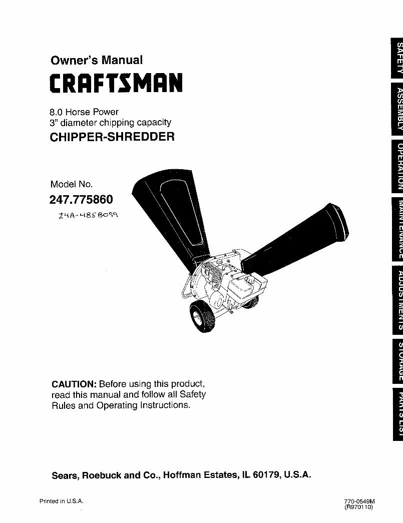
Content Page Content Page
Warranty Information 2 Service & Adjustment 14
Safe Operation Practices 3 Off-Season Storage 17
Assembly 5 Trouble-Shooting 18
Operation 8 Repair Parts 19
Maintenance 11
One-Year Warranty on Craftsman Chipper-ShredderFor one year from the date of purchase, when this Craftsman chipper-shredder is maintained, lubricated, andtuned up according to the operating and maintenance instructions inthe operator's manual, Sears will repair, freeof charge, any defect in material or workmanship.
This warranty excludes the blades, chipper blades, flails, air cleaners, spark plugs, catcher bags and tires whichare expendable parts and become worn during normal use.
If this chipper-shredder is used for commercial or rental purposes, this warranty applies for only 30 days from thedate of purchase.
WARRANTY SERVICE IS AVAILABLE BY CONTACTING THE NEAREST SEARS SERVICE CENTER IN THEUNITED STATES. THIS WARRANTY APPLIES ONLY WHILE THIS PRODUCT IS IN USE IN THE UNITEDSTATES.
This warranty gives you specific legal rights, and you may also have other rights which vary from state to state.Sears, Roebuck and Co., D/817wa, Hoffman Estates, II 60179
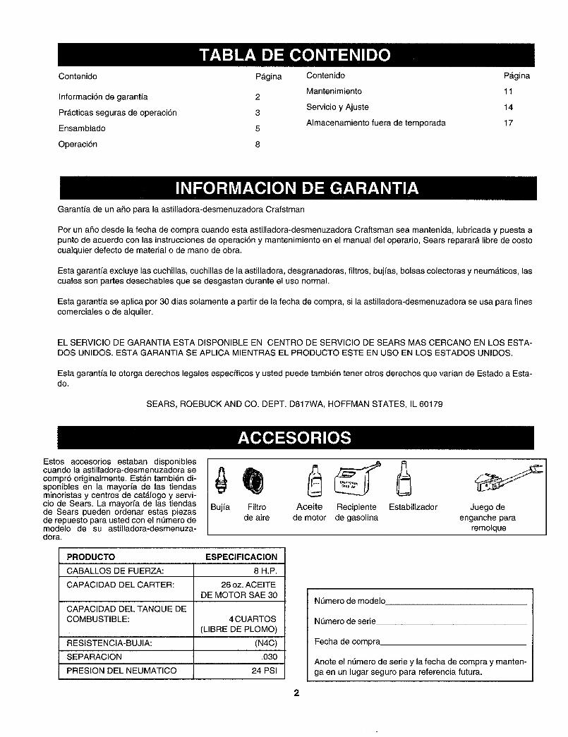
These accessories were
available when the chipper-
shredder was purchased.They are also available atmost Sears retail outlets,
catalog and service centers.Most Sears stores can order
repair parts for you when youprovide the model number of
your chipper-shredder.
Spark Air Engine Gas StabilizerPlug Filter Oil Can
Tow Hitch Kit
PRODUCT SPECIFICATION
HORSEPOWER: 8 H.P.
CRANKCASE CAPACITY: 26oz. SAE 30 ENGINE OIL
FULE TANK CAPACITY: 4 Quart (UNLEADED)
RESISTOR SPARK PLUG: (N4C)
GAP .030
TIRE PRESSURE 24 PSI
Model Number .........................................................
Serial Number ...........................................................
Date of Purchase ......................................................
Record both serial number and date of purchase andkeep in a safe place for future reference.
2
This symbol points out important safety instructions which, if not followed, could endanger the per-sonal safetyand/or property of yourselfand others.Read and follow all instructionsin this manual beforeattemptingto operate your chipper shredder.Failure to comply with these instructionsmay result inper-sonal injury.When you see thissymbol--heed its warning.
Your chipper-shredder was built to be operated according to the rules for safe operation in
DANGER: this manual. As with any type of power equipment, carelessness or error on the part of the oper-ator can result in serious injury. If you violate any of these rules, you may cause seriousinjury to yourself or others.
,_ WARNING: The Engine Exhaust from this product contains chemicals known to the State of Californiato cause cancer, birth defects or other reproductive harm.
1. GENERAL OPERATION
Read this owner's guide carefully in its entirety beforeattempting to assemble this machine. Read,understand, and follow all instructions on the machineand in the manual(s) before operation. Be completelyfamiliar with the controls and the proper use of the e
machine before operating it. Keep this manual in asafe place for future and regular reference and forordering replacement parts.Your chipper-shredder is a powerful tool, not aplaything. Therefore, exercise extreme caution at alltimes. Your unit has been designed to perform twojobs; to chip and shred vegetation found in a normal m
yard. Do not use it for any other purpose.Never allow children under age 16 to operate the unit. •Children 16 years and older should only operate theunit under close parental supervision. Onlyresponsible individuals who are familiar with theserules of safe operation should be allowed to use yourunit.
Keep the area of operation clear of all persons,
particularly small children and pets. Stop the engine owhen they are in the vicinity of the unit. Keep workarea clean and clear of branches or obstacles which
could cause you to stumble or fall.When feeding material into this equipment, be
e
extremely careful that pieces of metal, rocks, bottles,cans or other foreign objects are not included. ®
Personal injury or damage to the machine could result. e
Always wear safety glasses or safety goggles, duringoperation and while performing an adjustment orrepair, to protect eyes from foreign objects that may bethrown from the machine.
Wear sturdy, rough-soled work shoes and close fittingslacks and shirt. Shirt and slacks that cover the arms
and legs and steel-toed shoes are recommended. Donot wear loose fitting clothes or jewelry and secure hairso it is above shoulder length. They can be caught in
moving parts. Never operate a unit in bare feet,sandals or sneakers. Wear gloves when feedingmaterial in the chipper chute or shredder hopper.
Never place your hands, feet, or any part of your bodyinto the shredder hopper, chipper chute, dischargeopening, or near any moving part while the engine isrunning. Keep clear of the discharge opening at alltimes. If it becomes necessary to push material intothe chipper chute or shredder hopper, use a smalldiameter stick, NOT YOUR HANDS.
If it is necessary for any reason to unclog the feedintake or discharge openings or to inspect or repair anypart of the machine where a moving part can come incontact with your body or clothing, stop the machine,allow it to cool, disconnect the spark plug wire from thespark plug and move it away from the spark plugbefore attempting to unclog, inspect or repair.Do not operate unit while under the influence of alcoholor drugs.The machine should only be operated on a level
surface. Never operate your unit on a slippery, wet,muddy or icy surface. Keep your work area clean andclear of branches or obstacles which could cause youto stumble and fall. Do not overreach. Maintaining
proper footing and balance is essential to preventingaccidents.
Do not allow an accumulation of processed material tobuild up in the discharge area as this will preventproper discharge and can result in kick-back from thechipper chute.Keep your face and body back from chipper chute toavoid accidental bounce back of any material.Do not transport machine while engine is running.If the cutting mechanism strikes a foreign object or ifyour machine should start making an unusual noise orvibration, immediately stop the engine and allow themachine to come to a complete stop. Disconnect thespark plug wire and move it away from the spark plug.Take the following steps.
a. Inspect fordamage.b. Repair or replace any damaged parts.c. Check for any loose parts and tighten to assure
continued safe operation.Never attempt to attach or remove catcher bag whenengine is running. Shut the engine off and wait for the
e
impeller to come to a complete stop. The impellercontinues to rotate for a few seconds after the engineis shut off. Never place any part of the body in theimpeller area until you are sure the impeller hasstopped rotating.Muffler and engine become hot and can cause a burn.Do not touch.
Do not allow leaves or other debris to build-up onengine's muffler. The debris could ignite and cause afire.
Do not attempt to shred or chip material larger thanspecified in this manual. Personal injury or damage tothe machine could result.
Do not operate engine if air cleaner or cover overcarburetor air-intake is removed, except foradjustment. Removal of such parts could create a firehazard.
Only use accessories approved for this machine by themanufacturer. Read, understand, and follow all
instructions provided with the approved accessory.If situations occur which are not covered by thismanual, use care and good judgment. Contact yourdealer for assistance.
Keep discharge chute deflector, chipper chute door,and all other guards and safety devices in place andoperating properly.Only operate unit in good daylight. Do not operate unitat night or in dark areas where your vision may beimpaired.
2. CHILDREN
Tragic accidents can occur if the operator is not alert to thepresence of small children. Children are often attracted tothe chipper-shredder and the chipping and shreddingactivity. Never assume that children will remain where youlast saw them.
• Keep children out of the work area and under thewatchful eye of a responsible adult other than the
operator.• Be alert and turn the unit off if a child enters the area.
• Never allow children under the age of 16 to operate thechipper-shredder.
3. SERVICE• Use extreme care in handling gasoline and other fuels.
They are extremely flammable and the vapors areexplosive.
a. Store fuel and oil in approved containers, awayfrom heat and open flame, and out of the reach ofchildren. Check and add fuel before starting theengine. Never remove gas cap or add fuel whilethe engine is running. Allow engine to cool atleast two minutes before refueling.
b. Replace gasoline cap securely and wipe off anyspilled gasoline before starting the engine as itmay cause a fire or explosion.
c. Extinguish all cigarettes, cigars, pipes and othersources of ignition.
d. Never refuel unit indoors because flammable
vapors will accumulate in the area.e. Never store the machine or fuel container inside
where there is an open flame or spark such as agas hot water heater, space heater, clothes dryeror furnace.
Never run your machine in an enclosed area as theexhaust from the engine contains carbon monoxide,which is an odorless, tasteless and deadly poisonous
gas.To reduce fire hazard, keep engine and muffler free ofleaves, grass, and other debris build-up. Clean up fueland oil spillage. Allow unit to cool at least 5 minutesbefore storing.Before cleaning, repairing, or inspecting, make certainthe impeller and all moving parts have stopped.Disconnect the spark plug wire and keep wire awayfrom spark plug to prevent accidental starting. Do notuse flammable solutions to clean air filter.
Check the blade and engine mounting screws atfrequent intervals for proper tightness. Also visuallyinspect blades for wear and/or damage (e.g., bent,cracked). Replace with blades which meet originalequipment specifications.Keep all nuts, bolts, and screws tight to be sure theequipment is in safe working condition.Never tamper with safety devices. Check their properoperation regularly.After striking a foreign object, immediately stop theengine, disconnect the spark plug wire from the sparkplug, and thoroughly inspect the unit for any damage.Repair damage before starting and operating unit.Do not alter or tamper with the engine's governorsetting. The governor controls the maximum safeoperating speed of the engine. Over-speeding theengine is dangerous and will cause damage to theengine and to other moving parts of the machine.
4. YOUR RESPONSIBILITY
Restrict the use of this power machine topersons who read, understand and follow thewarnings and instructions in this manual and onthe machine.
SAVETHESEINSTRUCTIONSFOR FUTUREREFERENCE.
This unit is equipped with an internal combustion engine and should not be used on or near any unimproved forest-covered, brush-covered or grass-covered land unless the engine's exhaust system is equipped with a spark arrestermeeting applicable local or state laws (if any). If a spark arrester is used, it should be maintained in effective workingorder by the operator.In the State of California the above is required by law (Section 4442 of the California Public Resources Code). Otherstates may have similar laws. Federal laws apply on federal lands. A spark arrester for the muffler is available throughyour nearest Sears Authorized Service Center (See the REPAIR PARTS section of this manual.)
4
\
\\
Hopper
Discharge Chute
Chipper Chute
IMPORTANT: This unit is shipped without gasolineor oil inthe engine. After assembly, seeOPERATION section of this manual for proper fueland engine oil fill-up.
NOTE: To determine right and left hand sides of yourchipper-shredder, stand behind the unit with theengine farthest away from you.
Your chipper-shredder has been completely assembledat the factory, except for the hopper assembly, chipperchute, discharge chute and the catcher bag.These parts are shipped loose in the carton. A pair ofsafety glasses and a bottle of oil are also included inthe carton.
1. REMOVE CHIPPER-SHREDDERFROM CARTON
®
o
o
Q
4)
Cut the corners of the carton.Remove all packing inserts.Remove all loose parts including owner'smanual. See figure 1.Roll chipper-shredder out of the carton.Make certain all parts and literature have beenremoved before the carton is discarded.
2. LOOSE PARTS
a. Hopper Assemblyb. Discharge Chutec. Chipper Chuted. Catcher Bage. Bottleof Oil
f. Safety Glassesg. Owner's Manual (not shown in figure 1)
Catcher BagBottleof Oil
SafetyGlasses
Figure 1
3. TOOLS REQUIRED
1. 1/2" or Adjustable Wrenches2. 7/16" or Adjustable Wrenches3. Funnel
4. DISCONNECTING SPARK PLUG
Disconnect the spark plug wire and move itaway from the spark plug before assembling thechipper-shredder. See figure 2.
r_ /Spark Plug Wire
Figure 2
5. A'I-rACHING DISCHARGE CHUTE
Remove the wing knobs from each side of thedischarge opening on the chipper-shredder. Seefigure 3.Using two 7/16" wrenches, remove hex locknut, two spacers, and the hex bolt from top ofthe housing assembly. For easy assembly, donot remove the second spacer from the hex bolt.Place the discharge chute in position on thedischarge opening. Insert hex bolt and spacerthrough hinge on discharge chute and housing(spacer fits inside of hinge). See figure 3 inset.
Place second spacer over hex bolt inside theother part of the hinge. Secure with hex lock nut.Tighten securely.Secure both sides of discharge chute to housingusing wing knobs that you earlier removed.Tighten wing knobs.
6. A'n'ACHING HOPPER ASSEMBLY
Remove the 8-3/8" long hex bolt and the hex nutfrom the bottom of the inlet guide opening.Place the hopper assembly on the ground andhold it in the position shown in step 1 in figure 4.Holding the hopper, push hopper pivot doordown inside the hopper. See figure 4.Slide the hopper assembly towards the chipper-shredder housing so that the upper guide on thehopper assembly slides under the stop washeron each side of the inlet guide. See figure 4.Align the two holes (one on each side) of thelower hopper with the two holes (one on eachside) of the inlet guide.Insert the hex bolt (that you earlier removed)from the left through the hole on the hopper andthe inlet guide. Insert the hex nut onto the boltfrom the other side. See figure 4 inset.
Hopper Pivot Door
Inlet Guide Opening
Hopper HexNut
J
J
Hex Nut
Hex Bolt
Hinge
Stop
\
Knob
DischargeChute
Figure 3Knob
6
Inlet Guide Hopper
Figure 4
t
o
Q
Tighten the bolt. This will secure the hopperassembly to the inlet guide.To raise the hopper, hold the hopper by thehand-hold and lift it up till it clicks into position.To Iowerthe hopper, hold the hopper by thehand-hold and pull the release bar. The hoppershould drop down. See figure 5.
1. Lift hopper up
, /
2. Pull release bar
Figure 5
7. ATTACHING THE CHIPPERCHUTE
Remove the three cupped washers and hexnuts from the weld studs beside the opening onthe left side of the housing. See figure 6.
Weld Stud
Hex Nut
Brace
Weld Stud
Discharge Chute
Figure 6
o
o
Q
®
Remove the two sets of hex bolt, lock nut, andflat washer from the two holes on the upper endof the brace.
Place the chipper chute over the weld studs sothe slot on the chute is towards the bottom. Alignthe three holes on the chute with the three weldstuds. See figure 6.Secure with the three pairs of cupped washersand hex nuts that you earlier removed. Do nottighten the nuts at this time. Make sure to placethe cupped side of the washer against thechipper chute.Your unit is shipped with one end of the bracealready secured to the lower frame. Loosen thebolts securing the brace to the frame.Align the holes on the chute with the holes onthe brace. See figure 6.Insert one each of the hex bolts, lock nuts, andflat washers (that you earlier removed) througheach hole in the chute and the brace. See figure6 for the correct order. Tighten the bolts.Tighten the bolts securing the brace to the frame.Tighten the three nuts on the weld studs.
8. ATTACHING THE CATCHER BAG
Your chipper-shredder is equipped with a catcher bagto catch the shredded material.
• To attach the bag, place the opening of the bagover the chute deflector so it completely coversthe chute deflector.
• Depress the plunger on the draw- string, and pullon the drawstring until the bag is tight around thechute opening. Release plunger to lock it intoposition. See figure 7.
Plunger
Catcher
Figure 7
Read this owner's manual and safety rules before operating your chipper-shredder. Compare the illustrationswith your chipper-shredder to familiarize yourself with the location of various controls and adjustments. Savethis manual for future reference.The operation of any chipper-shredder can result in foreign objects being thrown into the eyes, which can resultin severe eye damage. Always wear safety glasses provided with the chipper-shredder or eye shields beforechipping or shredding, or while performing any adjustments or repairs.
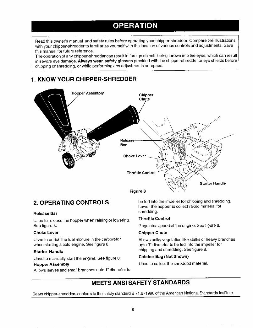
1. KNOW YOUR CHIPPER-SHREDDER
?per Assembly ChipperChute
q',\
R:lreaSe !
C
Starter Handle
2. OPERATING CONTROLS
Release Bar
Used to release the hopper when raising or lowering.See figure 8.
Choke Lever
Used to enrich the fuel mixture in the carburetorwhen starting a cold engine. See figure 8.
Starter Handle
Used to manually start the engine. See figure 8.
Hopper AssemblyAllows leaves and small branches upto 1" diameter to
be fed into the impeller for chipping and shredding.Lower the hopper to collect raked material forshredding.
Throttle Control
Regulates speed of the engine. See figure 8.
Chipper Chute
Allows bulky vegetation like stalks or heavy branchesupto 3" diameter to be fed into the impeller forchipping and shredding. See figure 8.
Catcher Bag (Not Shown)
Used to collect the shredded material.
MEETS ANSI SAFETY STANDARDS
Sears chipper-shreddersconformto the safety standard B 71.6 -1990 of the American National Standards Institute.
8
Stopping Engine
Move throttle control lever to STOP position.Disconnect spark plug wire and move away fromspark plug to prevent accidental starting.
WARNING: Before using your chipper-shredder, again refer to the safety rules onpage 3 and 4 of this manual. Always becareful.
3. GAS AND OIL FILL-UP
Oil (Packed with unit)
Only use high quality detergent oil rated withAPI service classification SF, SG or SH. Selectthe oil's viscosity grade according to yourexpected operating temperature. Follow thechart below.
Colder _ 32°F_ Warmer
5W30 [ SAE 30
NOTE: Although multi-viscosity oils (5W30, 10W30,etc.) improve starting in cold weather, thesemultiviscosity oils will result in increased oilconsumption when used above 32°F. Check the oillevel more frequently to avoid possible enginedamage from running low on oil.
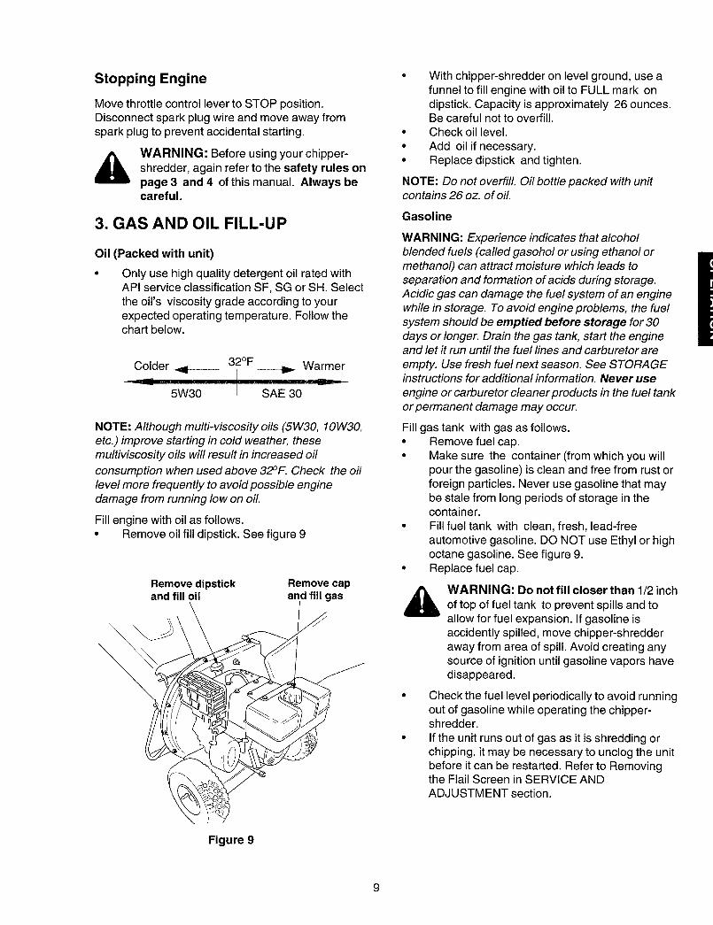
Fill engine with oil as follows.• Remove oil fill dipstick. See figure 9
Remove dipstickand fill oil
Figure 9
Remove capand fill gas
o
o
With chipper-shredder on level ground, use afunnel to fill engine with oil to FULL mark ondipstick. Capacity is approximately 26 ounces.Be careful not to overfill.Check oil level.Add oil if necessary.Replace dipstick and tighten.
NOTE: Do not overfill. Oil bottle packed with unitcontains 26 oz. of oil.
Gasoline
WARNING: Experience indicates that alcoholblended fuels (called gasohol or using ethanol ormethanol) can attract moisture which leads toseparation and formation of acids during storage.Acidic gas can damage the fuel system of an enginewhile in storage. To avoid engine problems, the fuelsystem should be emptied before storage for 30days or longer. Drain the gas tank, start the engineand let it run until the fuel lines and carburetor areempty. Use fresh fuel next season. See STORAGEinstructions for additional information. Never use
engine or carburetor cleaner products in the fuel tankor permanent damage may occur.
Fill gas tank with gas as follows.• Remove fuel cap.• Make sure the container (from which you will
pour the gasoline) is clean and free from rust orforeign particles. Never use gasoline that maybe stale from long periods of storage in thecontainer.
• Fill fuel tank with clean, fresh, lead-freeautomotive gasoline. DO NOT use Ethyl or highoctane gasoline. See figure 9.
. Replace fuel cap.
WARNING: Do not fill closer than 1/2 inch
of top of fuel tank to prevent spills and toallow for fuel expansion. If gasoline isaccidently spilled, move chipper-shredderaway from area of spill. Avoid creating anysource of ignition until gasoline vapors havedisappeared.
Check the fuel level periodically to avoid runningout of gasoline while operating the chipper-shredder.
If the unit runs out of gas as it is shredding orchipping, it may be necessary to unclog the unitbefore it can be restarted. Refer to Removingthe Flail Screen in SERVICE ANDADJUSTMENT section.
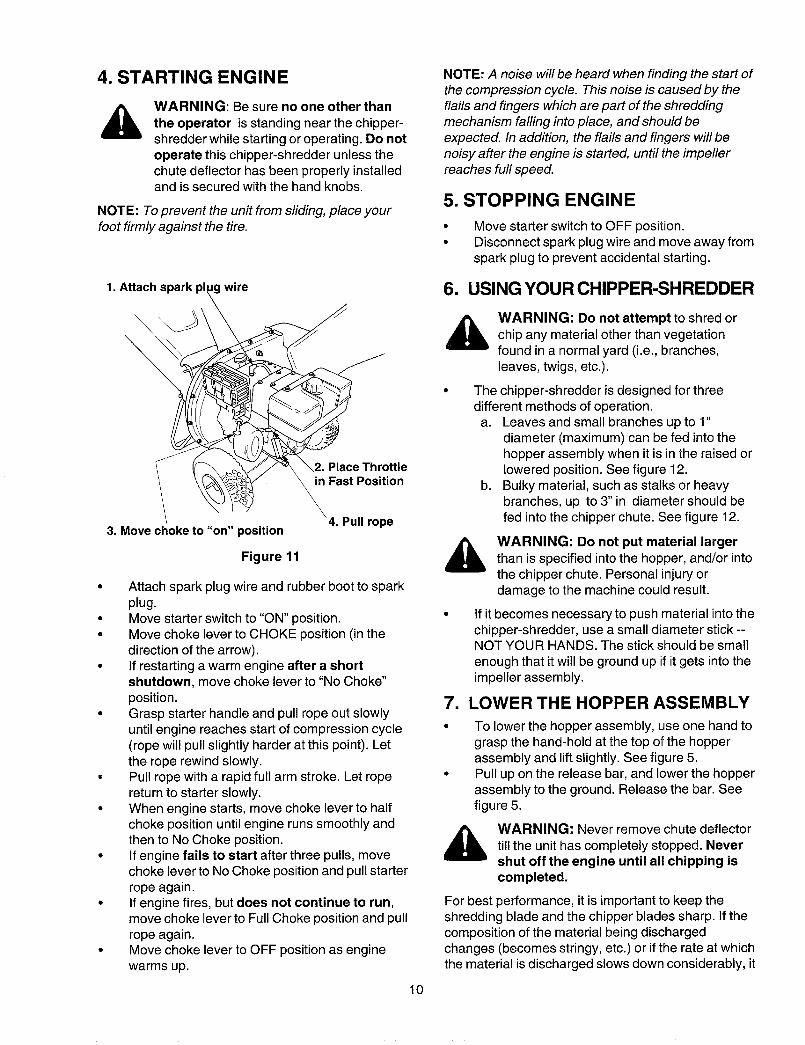
4. STARTING ENGINE
WARNING: Be sure no one other than
the operator is standing near the chipper-shredder while starting or operating. Do notoperate this chipper-shredder unless thechute deflector has been properly installedand is secured with the hand knobs.
NOTE: To prevent the unit from sliding, place yourfoot firmly against the tire.
1. Attach spark pl Jg wire
\
@
@
@
3. Move choke to "on" position
Figure 11
Place Throttlein Fast Position
\
_4. Pull rope
Attach spark plug wire and rubber boot to sparkplug.Move starter switch to "ON" position.Move choke lever to CHOKE position (in thedirection of the arrow).If restarting a warm engine after a shortshutdown, move choke lever to "No Choke"position.Grasp starter handle and pull rope out slowlyuntil engine reaches start of compression cycle(rope will pull slightly harder at this point). Letthe rope rewind slowly.Pull rope with a rapid full arm stroke. Let ropereturn to starter slowly.When engine starts, move choke lever to halfchoke position until engine runs smoothly andthen to No Choke position.If engine fails to start after three pulls, movechoke lever to No Choke position and pull starterrope again.If engine fires, but does not continue to run,move choke lever to Full Choke position and pullrope again.Move choke lever to OFF position as enginewarms up.
10
NOTE: A noise will be heard when finding the start ofthe compression cycle. This noise is caused by theflails and fingers which are part of the shreddingmechanism falling into place, and should beexpected. In addition, the flails and fingers will benoisy after the engine is started, until the impellerreaches full speed.
5. STOPPING ENGINE
Move starter switch to OFF position.Disconnect spark plug wire and move away fromspark plug to prevent accidental starting.
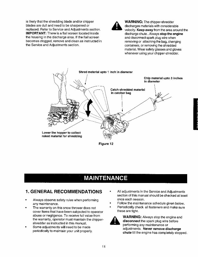
6. USING YOUR CHIPPER-SHREDDER
WARNING: Do not attempt to shred orchip any material other than vegetationfound in a normal yard (i.e., branches,leaves, twigs, etc.).
The chipper-shredder is designed for threedifferent methods of operation.
a. Leaves and small branches up to 1"diameter (maximum) can be fed into thehopper assembly when it is in the raised orlowered position. See figure 12.
b. Bulky material, such as stalks or heavybranches, up to 3" in diameter should befed into the chipper chute. See figure 12.
WARNING: Do not put material largerthan is specified into the hopper, and/or intothe chipper chute. Personal injury ordamage to the machine could result.
If it becomes necessary to push material into thechipper-shredder, use a small diameter stick --NOT YOUR HANDS. The stick should be small
enough that it will be ground up if it gets into theimpeller assembly.
7. LOWER THE HOPPER ASSEMBLY
To lower the hopper assembly, use one hand tograsp the hand-hold at the top of the hopperassembly and lift slightly. See figure 5.Pull up on the release bar, and lower the hopperassembly to the ground. Release the bar. Seefigure 5.
WARNING: Never remove chute deflectortill the unit has completely stopped. Nevershut off the engine until all chipping iscompleted.
For best performance, it is important to keep theshredding blade and the chipper blades sharp. If thecomposition of the material being dischargedchanges (becomes stringy, etc.) or if the rate at whichthe material is discharged slows down considerably, it
is likelythattheshreddingbladeand/orchipperbladesaredullandneedtobesharpenedorreplaced.RefertoServiceandAdjustmentssection.IMPORTANT:Thereisaflailscreenlocatedinsidethehousinginthedischargearea.Iftheflailscreenbecomesclogged,removeandcleanasinstructedintheServiceandAdjustmentssection.
WARNING:Thechipper-shredderdischargesmaterialswithconsiderablevelocity.Keepaway from the area around thedischarge chute. Always stop the engineand disconnect spark plug wire whenremoving or attaching the bag, changingcontainers, or removing the shreddedmaterial. Wear safety glasses and gloveswhenever using your chipper-shredder.
Shred material upto 1 inch in diameter
/ Chip material upto 3 inchesin diameter
Catch shredded materialin catcher bag
Lower the hopper to collectraked material for shredding
Figure 12
1. GENERAL RECOMMENDATIONS
o
o
Always observe safety rules when performingany maintenance.The warranty on this snow thrower does notcover items that have been subjected to operatorabuse or negligence. To receive full value fromthe warranty, operator must maintain the chipper-shredder as instructed in this manual.Some adjustments will need to be madeperiodically to maintain your unit properly.
All adjustments in the Service and Adjustmentssection of this manual should be checked at leastonce each season.Follow the maintenance schedule given below.Periodically check all fasteners and make surethese are tight.
WARNING: Always stop the engine anddisconnect the spark plug wire beforeperforming any maintenance oradjustments. Never remove dischargechute till the engine has completely stopped.
11
MAINTENANCE
CUSTOMER RESPONSIBILITIES
_ _" _ p p _o" SERVICE DATES
S
go.
u.IZm
ZILl
Oil pivot points
Clean shredder
Check engine oil
Change engine oil
Service air cleaner
Clean engine
Reset spark plug
Clean muffler
2. CLEANING
Clean the chipper-shredder by running waterfrom a hose through the hopper assembly andchipper chute with the engine running. Allowthe chipper-shredder to dry thoroughly.Wash the bag periodically with water. Allow todry thoroughly in the shade. Do not use heat.
3. ENGINE MAINTENANCE
Engine Oil
• Only use high quality detergent oil rated withAPI service classification SF, SG or SH. Selectthe oil's viscosity grade according to yourexpected operating temperature. Refer topage 9 of this manual for viscosity chart.
• The four-cycle engine of your chipper-shredder will normally consume some oil.Therefore, check engine oil level regularlyapproximately every five hours of operationand before each usage.
• Stop engine and wait several minutes before
checking oil level. With engine on level ground,the oil must be to FULL mark on dipstick.Change engine oil after the first five hours ofoperation, and every twenty-five hoursthereafter.
To Drain Oil
Drain oil while engine is warm. Follow theinstructions given below.• Remove oil drain plug. Catch oil in a suitable
container.• When engine is drained of all oil, replace drain
plug securely.• Refill with fresh oil. Refer to GAS AND OIL
FILL-UP section.• Replace dipstick.
Air Cleaner
The air cleaner prevents damaging dirt, dust, etc.,from entering the carburetor and being forced intothe engine and is important to engine life andperformance. The air cleaner consists of a pre-cleaner or foam filter, and a paper filter. Never run
12
theenginewithoutaircleanercompletelyassembled.ToServiceAir Cleaner:
1. Service pre-cleaner after every 25 hours of use,or at least once a season.
2. Service filter every 100 hours of use, or at leastonce a season.
3. Service pre-cleaner and filter more often underdusty conditions.
- Remove wing nut and cover.• Slide pre-cleaner off filter. Clean the inside of
base and cover thoroughly.
LFins
NUT
PAPER FOAMFILTER(IF SOEQUIPPED)
Figure 13
Clean pre-cleaner as follows:a. Wash in water and detergent solution, and
squeeze (do not twist) until all dirt isremoved.
b. Rinse thoroughly in clear water.c. Wrap in a clean cloth and squeeze (do not
twist) until completely dry, or allow to air dry.d. Saturate with engine oil and squeeze (don't
twist) to distribute oil and remove excess oil.
NOTE: If the pre-cleaner is torn or damaged in anyway, replace it.
• If necessary, replace paper filter (do not attemptto clean). Install new filter on base.
• Slide pre-cleaner over filter.• Install cover and wing nut.° Tighten wing nut securely.
Clean Engine
• Clean engine periodically. Remove dirt anddebris with a cloth or brush.
° Frequently remove grass clippings, dirt anddebris from cooling fins, air intake screen andlevers and linkage. This will help ensureadequate cooling and correct engine speed.See figure 14
Figure 14
Yearly or every 25 hours, whichever occurs first,remove the blower housing and clean the areasshown in figure 14 to avoid overspeeding,overheating and engine damage. Clean moreoften if necessary.
NOTE: Cleaning with a forceful spray of water is notrecommended as water could contaminate the fuel
system.
WARNING: Temperature of muffler andnearby areas may exceed 150° F(65°C).Avoid these areas.
Spark Plug
Clean the spark plug and reset the gap to .030"at least once a season or every 50 hours ofoperation. See figure 15. Spark plugreplacement is recommended at the start ofeach season. Refer to engine parts list forcorrect spark plug type.
.030" Feeler Gauge
zrk Plug
Figure 15
NOTE: Do not sandblast spark plug. Spark plugshould be cleaned by scraping or wire brushing andwashing with a commercial solvent.
13
Muffler
WARNING: Do not operate the chipper-shredder without a muffler, or tamper withthe exhaust system. Damaged mufflers orspark arresters could create a fire hazard.
Inspect periodically, and replace if necessary. Ifyour engine is equipped with a spark arresterscreen assembly, remove every 50 hours forcleaning and inspection. Replace if damaged.
WARNING: Always stop engine,disconnect spark plug wire, and move itaway from spark plug before performingany adjustments or repairs.
4. LUBRICATION
Lubricate the pivot points on the release bar, hopperassembly, chute deflector and chipper chute once aseason using a light oil. See figure 16
Figure 16: Lubrication Chart
1. REMOVING THE FLAILSCREEN
If the discharge area becomes clogged, removethe flail screen and clean area as follows.• Stop engine, make certain the chipper-
shredder has come to a complete stop anddisconnect spark plug wire from the sparkplug before unclogging the chute.
• Remove the two hand knobs on each side of
the discharge chute (also called the chutedeflector).
° Lift the discharge chute up, and keep it outof the way.
• Remove two hairpin clips from the clevispins which extend through the housing.Remove the clevis pins. See figure 17.
• Pull the flail screen from inside the housing.See figure 17.
• Clean the screen by scraping or washingwith water.
• Reinstall the screen.
• Put the discharge chute back to its originalposition and tighten the hand knobs.
NOTE: Be certain to reassemble the flail screenwith the curved side down.
HairpinClips,Clevis
Pins
Nuts,Washers
FlailScreen
cHand Knobs
Figure 17
14
2. SHARPENING OR REPLACINGTHE BLADES
Chipper Blades
Disconnect spark plug wire and move it awayfrom spark plug.Remove the flail screen as instructed in
previous section.Using a 1/2" wrench, remove the chipper chuteby removing three hex nuts and washers. Seefigure 17.Using a 7/16" wrench, remove the brace(holding the chute to the frame) by removing thehex bolts.
NOTE: When re-assembling, the cupped washergoes on the slot toward the bottom of the chipperchute with the cupped side against the chute.
Rotate the impeller assembly by hand until youlocate one of the two chipper blades in thechipper chute opening. Remove the blade, usinga 3/16" allen wrench on the outside of the bladeand 1/2" wrench on the impeller assembly(inside the housing). See figure 18.
o
Sharp EdgeFigure 18
Remove the other blade in the same manner.Replace or sharpen blades.If sharpening, make certain to remove an equalamount from each blade.Reassemble in reverse order. Make certain
blades are reassembled with the sharp edgefacing the direction shown in figure 18 (sharpedge is assembled toward the slotted opening atthe bottom).Torque bolts and nuts to 250-350 inch-pounds.
Shredding Blade
The shredding blade may be removed for sharpeningor replacement as follows.• Disconnect spark plug wire and move it away
from spark plug.• Lower the hopper assembly. Block up the
housing. See figure 19.
AllenScrews
fPipe
BladeWrench
Figure 19
• Remove the six hex lock nuts and lock washers
from the housing weld bolts using a 1/2" wrench.Separate the chipper-shredder into two halves.
• Remove the back-up plate.
NOTE: When reassembling, make certain theembossed tab faces inward towards the impeller, andopening on the back-up plate is toward the bottom ofthe unit.
Remove the two hand knobs and cuppedwashers which secure the chute deflector. Raisethe chute deflector.
Insert a 1/2" or 3/4" diameter pipe through theflail screen into the impeller to keep it fromturning, or remove the flail screen and insert apiece of wood (2 x 4) into the chute opening.Remove the two outside screws on the blade,using a 3/16" allen wrench and a 1/2" wrench.Remove the blade by removing the center bolt,lock washer and flat washer.
_ WARNING: Use caution when removingthe blade to avoid contacting the weld boltson the housing.
When sharpening the blade, follow the originalangle of grind as a guide. It is extremelyimportant that each cutting edge receives an
15
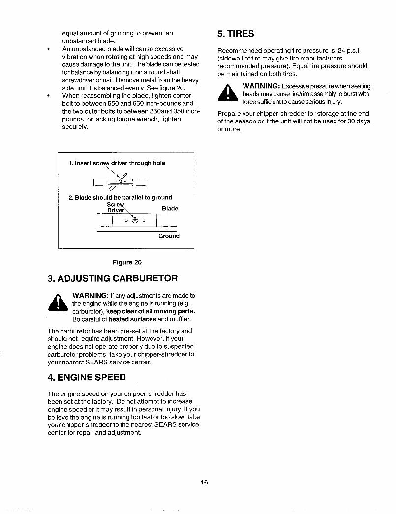
equalamountofgrindingto preventanunbalancedblade.Anunbalancedbladewillcauseexcessivevibrationwhenrotatingathighspeedsandmaycausedamagetotheunit.Thebladecanbetestedforbalancebybalancingitonaroundshaftscrewdriverornail.Removemetalfromtheheavysideuntilit isbalancedevenly.Seefigure20.Whenreassemblingtheblade,tightencenterbolttobetween550and650inch-poundsandthetwoouterboltstobetween250and350inch-pounds,or lackingtorquewrench,tightensecurely.
5. TIRES
Recommended operating tire pressure is 24 p.s.i.(sidewall of tire may give tire manufacturersrecommended pressure). Equal tire pressure shouldbe maintained on both tires.
_ ARNING: Excessive pressure when seatingbeads may cause tire/rim assembly to burst withforce sufficient to cause serious injury.
Prepare your chipper-shredder for storage at the endof the season or if the unit will not be used for 30 daysor more.
1. Insert screw driver through hole
d./
2. Blade should be parallel to groundScrev_Driver_ Bla_d_e
/
Ground
Figure 20
3. ADJUSTING CARBURETOR
WARNING: If any adjustments are made tothe engine while the engine is running (e.g.carburetor), keep clear of all moving parts.Be careful of heated surfaces and muffler.
The carburetor has been pre-set at the factory andshould not require adjustment. However, if yourengine does not operate properly due to suspectedcarburetor problems, take your chipper-shredder toyour nearest SEARS service center.
4. ENGINE SPEED
The engine speed on your chipper-shredder hasbeen set at the factory. Do not attempt to increaseengine speed or it may result in personal injury. If youbelieve the engine is running too fast or too slow, takeyour chipper-shredder to the nearest SEARS servicecenter for repair and adjustment.
16
WARNING:Neverstoremachinewithfuelinthefueltankinsideofbuildingwherefumesmayreachan open flame or spark,or where ignition sources are present suchas hot water and space heaters, furnaces,clothes dryers, stoves, electric motors, etc.
A yearly check-up by your local Sears service centeris a good way to make certain your chipper-shredderwill provide maximum performance for the nextseason.
1. CHIPPER-SHREDDER
Clean the chipper-shredder thoroughly.Wipe unit with an oiled rag to prevent rust (use alight oil or silicone).
2. ENGINE
IMPORTANT: It is important to prevent gum depositsfrom forming in essential fuel system parts such ascarburetor, fuel filter, fuel hose, or tank duringstorage. Also, experience indicates that alcoholblended fuels (called gasohol or using ethanol ormethanol) can attract moisture which leads toseparation and formation of acids during storage.Acidic gas can damage the fuel system of an enginewhile in storage.
Drain the fuel tank.Start the engine and let it run until the fuel linesand carburetor are empty.Drain carburetor by pressing upward on bowldrain which is located below the carburetor.
Never use engine or carburetor cleanerproducts in the fuel tank or permanent damagemay occur.Use fresh fuel next season.
NOTE: Fuel stabilizer is an acceptable alternative inminimizing the formation of fuel gum deposits duringstorage.
Add stabilizer to gasoline in fuel tank or storagecontainer.Always follow the mix ratio found on stabilizercontainer.Run engine at least 10 minutes after addingstabilizer to allow the stabilizer to reach the
carburetor.Do not drain the gas tank and carburetor if usingfuel stabilizer. Drain all the oil from thecrankcase (this should be done after the enginehas been operated and is still warm) and refillthe crankcase with fresh oil.If you have drained the fuel tank, protect theinside of the engine as follows.Remove spark plug, pour approximately 1/2ounce (approximately one tablespoon) of engineoil into cylinder and crank slowly to distribute oil.Replace spark plug.
3. OTHER
Do not store gasoline from one season toanother.Replace your gasoline can if your can starts torust. Rust and/or dirt in your gasoline will causeproblems. Store unit in a clean, dry area. Do notstore next to corrosive materials, such asfertilizer.
NOTE: If storing in an unventilated or metal storageshed, be certain to rustproof the equipment by coatingwith a light off or sificone.
17

PROBLEM POSSIBLE CAUSE CORRECTIVE ACTION
Engine fails to start
Loss of power; operation erratic
Engine overheats
Too much vibration
Unit does not discharge
Rate of discharge slowsconsiderably or composition ofdischarged material changes
1. Fuel tank empty, or stale fuel2. Spark plug wire disconnected3. Faulty spark plug4. Throttle control not in correct
position
1. Spark plug wire loose
2. Unit running on Choke
3. Blocked fuel line or stale fuel
4. Water or dirt in fuel system
5. Carburetor out of adjustment
6. Dirty air cleaner
1. Carburetor not adjusted properly
2. Engine oil level low
1. Loose parts or damagedimpeller
1. Discharge chute clogged
2. Foreign object lodged inimpeller
1. Shredding blade and/orchippingblade dull
1. Fill tank with clean, fresh fuel2. Connect wire to spark plug.3. Clean, adjust gap or replace.4. Move throttle control to FAST
position
1. Connect and tighten spark plugwire
2. Move choke lever to OFFposition
3. Clean fuel line; fill tank withclean, fresh gasoline.
4. Disconnect fuel line at carburetorto drain fuel tank. Refill with freshfuel.
5. Contact your SEARS servicecenter.
6. Service air cleaner.
1.
2.
1.
Contact your SEARS servicecenterFill crankcase with proper oil
Stop engine immediately anddisconnect spark plug wire.Tighten all bolts and nuts. Makeall necessary repairs. If vibrationcontinues, have unit servicedby a SEARS service center.
1. Stop engine immediately anddisconnect spark plug wire.clean flail screen and inside ofblower housing.
2. Stop engine immediately anddisconnect spark plug wire.Remove lodged object.
1. Sharpen or replace blade(s)
For repairs beyond the minor adjustments listed above, please contact your nearest SEARSservice center.
18
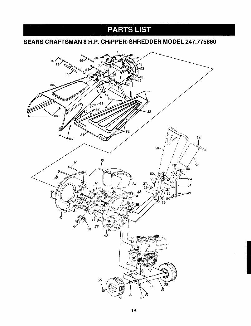
SEARS CRAFTSMAN 8 H.P. CHIPPER=SHREDDER MODEL 247.775860
79 76 8
_o_
16
82
.82
85
23
57
28
10
19
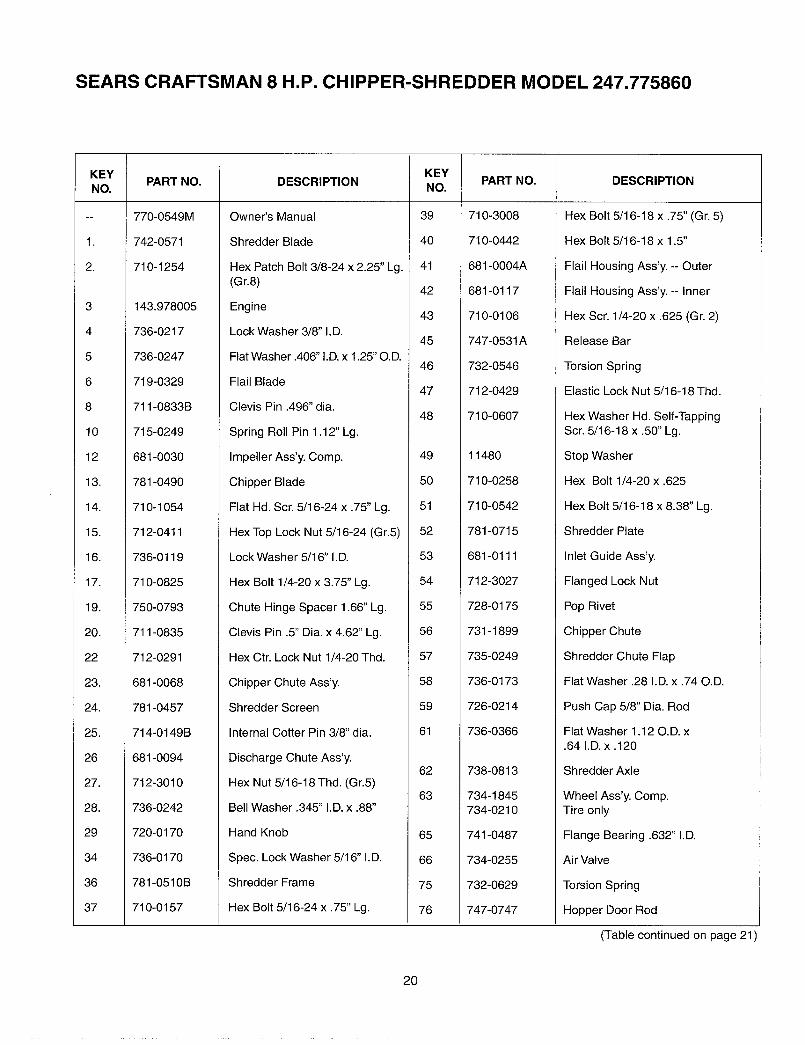
SEARS CRAFTSMAN 8 H.P. CHIPPER-SHREDDER MODEL 247.775860
L
KEYNO.
1.
2.
3
4
5
6
8
10
12
l&
14.
15.
16.
17.
19.
20.
22
23.
24.
25.
26
27.
28.
29
34
36
37
PART NO.
770-0549M
742-0571
710-1254
143,978005
736-0217
736-0247
719-0329
711-0833B
715-0249
681-0030
781-0490
710-1054
712-0411
736-0119
710-0825
750-0793
711-0835
712-0291
681-0068
781-0457
714-0149B
681-0094
712-3010
736-0242
720-0170
736-0170
781-0510B
710-0157
DESCRIPTION
Owner's Manual
Shredder Blade
Hex Patch Bolt 3/8-24 x 2.25" Lg.(Gr.8)
Engine
Lock Washer 3/8" I.D.
Flat Washer .406" I.D. x 1.25" O.D.
Flail Blade
Clevis Pin .496" dia.
Spring Roll Pin 1.12" Lg.
Impeller Ass'y. Comp,
Chipper Blade
Flat Hd. Scr. 5/16-24 x .75" Lg.
Hex Top Lock Nut 5/16-24 (Gr.5)
Lock Washer 5/16" I.D.
Hex Bolt 1/4-20 x 3.75" Lg.
Chute Hinge Spacer 1.66" Lg.
Clevis Pin .5" Dia. x 4.62" Lg.
Hex Ctr. Lock Nut 1/4-20 Thd.
Chipper Chute Ass'y.
Shredder Screen
Internal Cotter Pin 3/8" dia.
Discharge Chute Ass'y.
Hex Nut 5/16-18 Thd. (Gr.5)
Bell Washer .345" I.D. x .88"
Hand Knob
Spec. Lock Washer 5/16" I.D.
Shredder Frame
Hex Bolt 5/16-24 x .75" Lg.
KEYNO.
39
4O
41
42
43
45
46
47
48
49
5O
51
52
53
54
55
56
57
58
59
61
62
63
65
66
75
76
PART NO.
710-3008
710-0442
681-0004A
681-0117
710-0106
747-0531A
732-0546
712-0429
710-0607
11480
710-0258
710-0542
781-0715
681-0111
712-3027
728-0175
731-1899
735-0249
736-0173
726-0214
736-0366
738-0813
734-1845734-0210
741-0487
734-0255
732-0629
747-0747
DESCRIPTION
Hex Bolt 5/16-18 x .75" (Gr. 5)
Hex Bolt 5/16-18 x 1.5"
Flail Housing Ass'y. -- Outer
Flail Housing Ass'y. -- Inner
Hex Scr. 1/4-20 x .625 (Gr, 2)
Release Bar
Torsion Spring
Elastic Lock Nut 5/16-18 Thd.
Hex Washer Hd. Self-TappingScr. 5/16-18 x .50" Lg.
Stop Washer
Hex Bolt 1/4-20 x .625
Hex Bolt 5/16-18 x 8.38" Lg.
Shredder Plate
Inlet Guide Ass'y.
Flanged Lock Nut
Pop Rivet
Chipper Chute
Shredder Chute Flap
Flat Washer .28 I.D. x .74 O.D.
Push Cap 5/8" Dia. Rod
Flat Washer 1.12 O.D. x.64 I.D. x .120
Shredder Axle
Wheel Ass'y. Comp.Tire only
Flange Bearing .632" I.D.
Air Valve
Torsion Spring
Hopper Door Rod
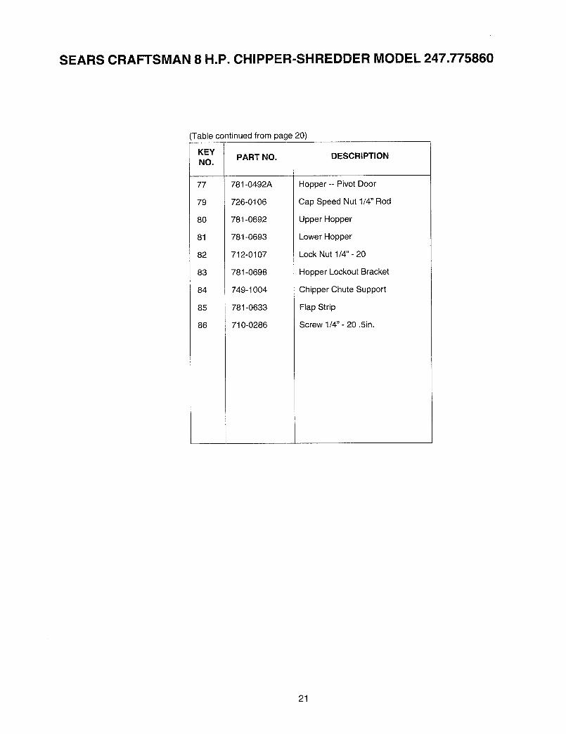
(Table continued on page 21)
20
SEARS CRAFTSMAN 8 H.P. CHIPPER-SHREDDER MODEL 247.775860
Table continued from page 20)
KEYNO.
77
79
8O
81
82
83
84
85
86
PART NO.
781-0492A
726-0106
781-0692
781-0693
712-0107
781-0698
749-1004
781-0633
710-0286
DESCRIPTION
Hopper -- Pivot Door
Cap Speed Nut 1/4" Rod
Upper Hopper
Lower Hopper
Lock Nut 1/4"- 20
Hopper Lockout Bracket
Chipper Chute Support
Flap Strip
Screw 1/4"- 20.5in.
21
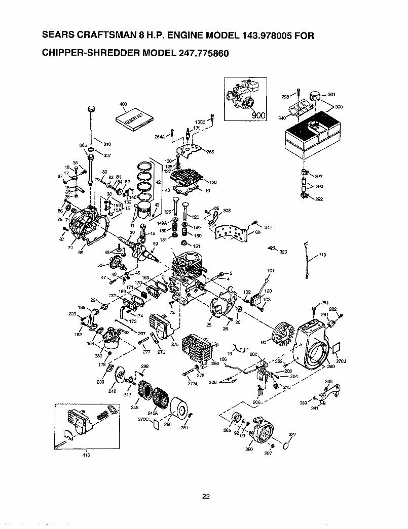
SEARS CRAFTSMAN 8 H.P. ENGINE MODEL 143.978005 FOR
CHIPPER-SHREDDER MODEL 247.775860
75 71
87
7069
ooo]
8083 81
89
47 •
342
t
_i__'_ 292
325 _..i't10101
>3OO
171169,
162 /184,
240
416
- \1
277 276
/245
245A
3700_.[_]-" 250
277A
/251
/25
26
22
SEARS CRAFTSMAN 8 H.P. ENGINE MODEL 143.978005 FOR
CHIPPER-SHREDDER MODEL 247.775860
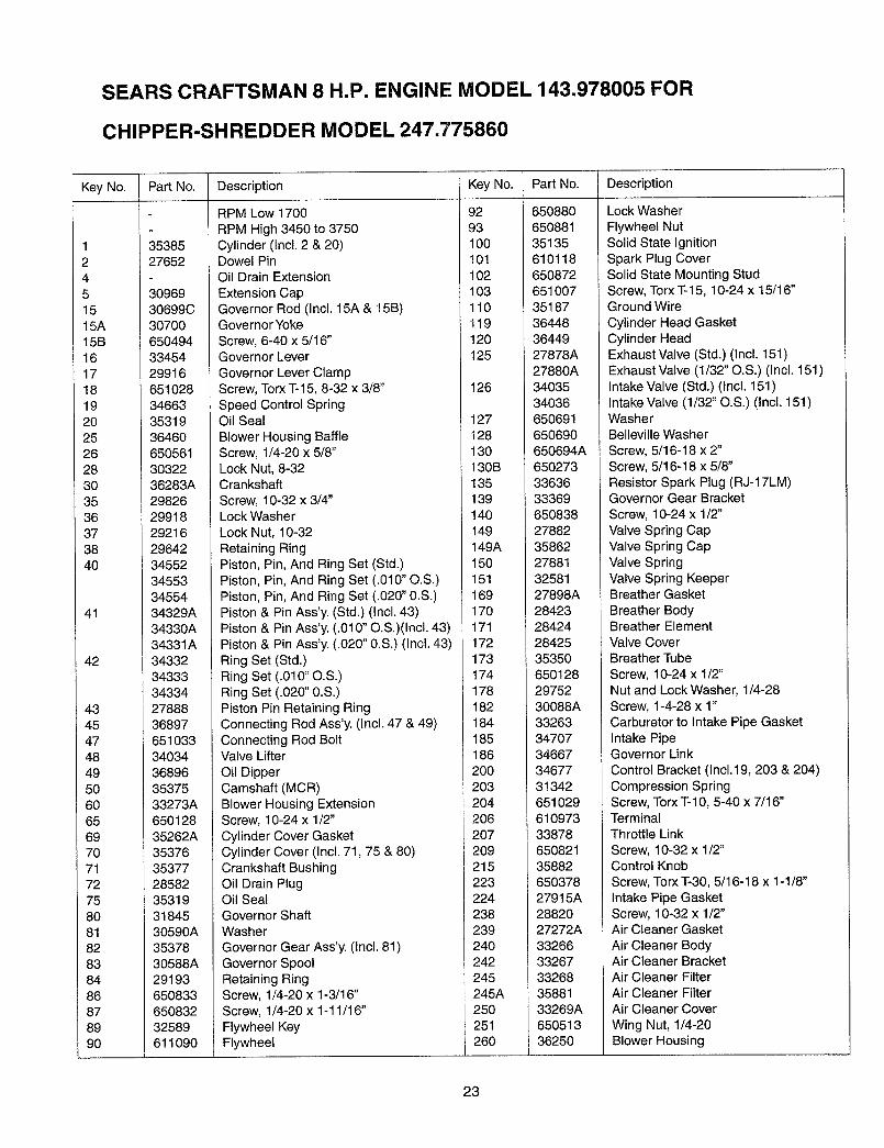
Key No.
12451515A15B1617181920252628303536373840
41
42
43454748495O606569707172758O8182838486878990
Part No.
3538527652
3096930699C30700
Description
RPM Low 1700
RPM High 3450 to 3750Cylinder (Incl. 2 & 20)Dowel PinOil Drain Extension
Extension CapGovernor Rod (Incl. 15A & 15B)Governor Yoke
Key No.
9293100101102103110119
Part No.
650880650881351356101186508726510073518736448
Description
Lock Washer
Flywheel NutSolid State IgnitionSpark Plug CoverSolid State Mounting StudScrew, Torx T-15, 10-24 x 15/16"Ground Wire
Cylinder Head Gasket65049433454299166510283466335319364606505613032236283A2982629918292162964234552345533455434329A34330A34331A343323433334334278883689765103334034368963537533273A65012835262A353763537728582353193184530590A3537830588A2919365083365083232589611O90
Screw, 6-40 x 5/16"Governor Lever
Governor Lever ClampScrew, Torx "1--15,8-32 x 3/8"Speed Control SpringOil Seal
Blower Housing BaffleScrew, 1/4-20 x 5/8"Lock Nut, 8-32CrankshaftScrew, 10-32 x 3/4"Lock Washer
Lock Nut, 10-32Retaining RingPiston, Pin, And Ring Set (Std.)Piston, Pin, And Ring Set (.010" O.S.)Piston, Pin, And Ring Set (.020" 0.S.)Piston & Pin Ass'y. (Std.) (Incl. 43)Piston & Pin Ass'y. (.010" O.S.)(Incl. 43)Piston & Pin Ass'y. (.020" 0.S.) (Incl. 43)Ring Set (Std.)Ring Set (.010" O.S.)Ring Set (.020" 0.S.)Piston Pin Retaining RingConnecting Rod Ass'y. (Incl. 47 & 49)Connecting Rod BoltValve Lifter
Oil DipperCamshaft (MCR)Blower Housing ExtensionScrew, 10-24 x 1/2"
Cylinder Cover GasketCylinder Cover (Incl. 71,75 & 80)Crankshaft BushingOil Drain PlugOil SealGovernor ShaftWasherGovernor Gear Ass'y. (Incl. 81)
Governor SpoolRetaining RingScrew, 1/4-20 x 1-3/16"Screw, 1/4-20 x 1-11/16"Flywheel KeyFlywheel
120125
126
127128130130B135139140149149A1501511691701711721731741781821841851862OO203
2042062O7209215223224238239240242
245245A25O251260
3644927878A27880A3403534036650691
650690650694A65027333636333696508382788235862278813258127898A284232842428425353506501282975230088A3326334707346673467731342651029610973338786508213588265037827915A2882027272A3326633267332683588133269A65051336250
Cylinder HeadExhaust Valve (Std.) (Incl. 151)Exhaust Valve (1/32" O.S.) (Incl. 151)Intake Valve (Std.) (Incl. 151)Intake Valve (1/32" O.S.) (Incl. 151)WasherBelleville Washer
Screw, 5/16-18 x 2"Screw, 5/16-18 x 5/8"Resistor Spark Plug (RJ-17LM)Governor Gear Bracket
Screw, 10-24 x 1/2"Valve Spring CapValve Spring CapValve SpringValve Spring KeeperBreather Gasket
Breather BodyBreather ElementValve CoverBreather Tube
Screw, 10-24 x 1/2"Nut and Lock Washer, 1/4-28Screw, 1-4-28 x 1"Carburetor to Intake Pipe GasketIntake PipeGovernor Link
Control Bracket (Inc1.19, 203 & 204)Compression SpringScrew, Torx T-10, 5-40 x 7/16"TerminalThrottle Link
Screw, 10-32 x 1/2"Control KnobScrew, Torx "1"-30,5/16-18 x 1-1/8"
Intake Pipe GasketScrew, 10-32 x 1/2"Air Cleaner Gasket
Air Cleaner BodyAir Cleaner BracketAir Cleaner FilterAir Cleaner FilterAir Cleaner Cover
Wing Nut, 1/4-20Blower Housing
23
SEARS CRAFTSMAN 8 H.P. ENGINE MODEL 143.978005 FOR
CHIPPER-SHREDDER MODEL 247.775860
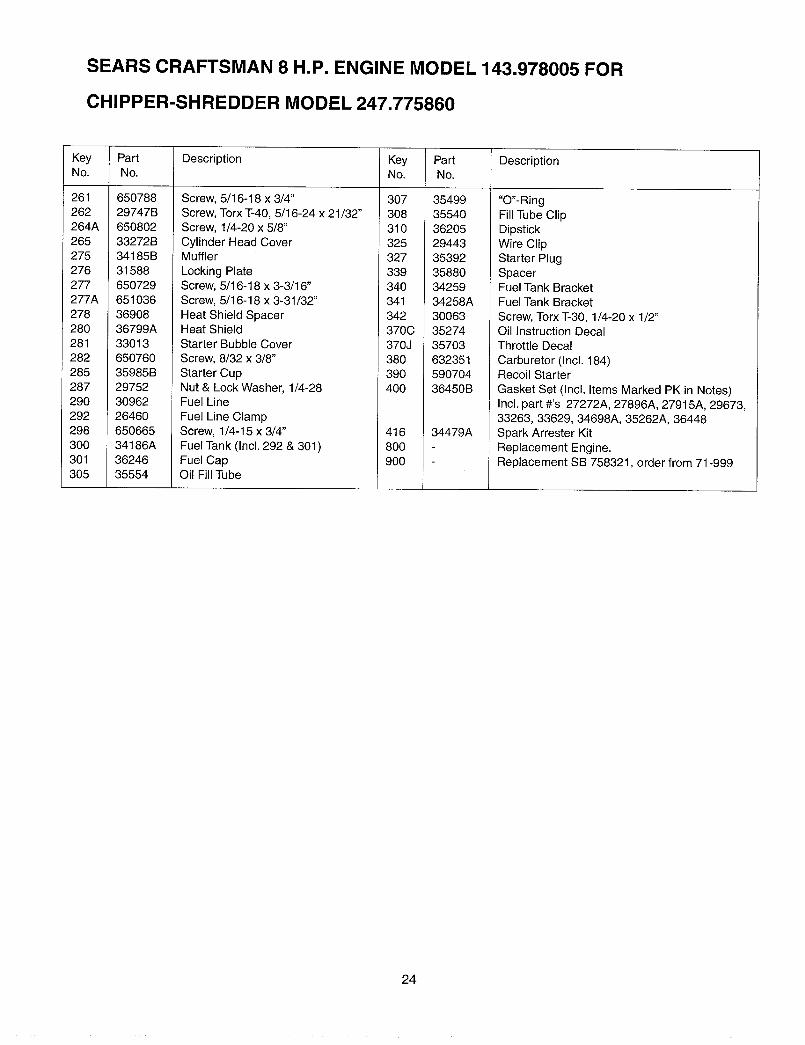
KeyNo.
261262264A265275276277277A278280281282285287290292298300301305
PartNo.
65078829747B65080233272B34185B315886507296510363690836799A3301365076035985B29752309622646065066534186A3624635554
Description Key PartNo. No.
Screw, 5/16-18 x 3/4"
Screw, Torx T-40, 5/16-24 x 21/32"Screw, 1/4-20 x 5/8"
Cylinder Head CoverMuffler
Locking PlateScrew, 5/16-18 x 3-3/16"Screw, 5/16-18 x 3-31/32"
Heat Shield SpacerHeat ShieldStarter Bubble Cover
Screw, 8/32 x 3/8"Starter CupNut & Lock Washer, 1/4-28Fuel Line
Fuel Line ClampScrew, 1/4-15 x 3/4"Fuel Tank (Incl. 292 & 301)Fuel CapOil Fill Tube
307 35499308 35540310 36205325 29443327 35392339 35880340 34259341 34258A
342 30063370C 35274370J 35703380 632351390 590704400 36450B
4168OO9OO
34479A
Description
"O"-RingFill Tube ClipDipstickWire ClipStarter PlugSpacerFuel Tank BracketFuel Tank Bracket
Screw, Torx T-30, 1/4-20 x 1/2"Oil Instruction DecalThrottle Decal
Carburetor (Incl. 184)Recoil Starter
Gasket Set (Incl. Items Marked PK in Notes)Incl. part #'s 27272A, 27896A, 27915A, 29673,33263, 33629, 34698A, 35262A, 36448Spark Arrester Kit
Replacement Engine.Replacement SB 758321, order from 71-999
24
SEARS CRAFTSMAN 8 H.P. ENGINE MODEL 143.978005 FOR
CHIPPER-SHREDDER MODEL 247.775860
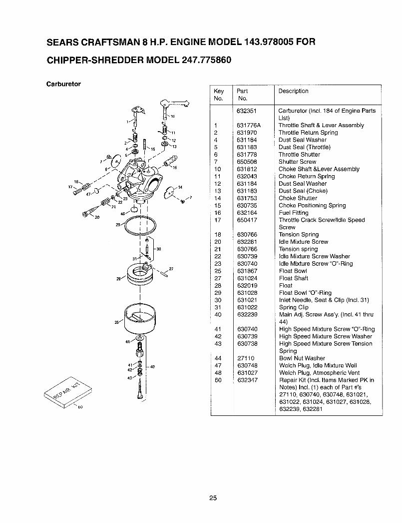
Carburetor
20
Key Part DescriptionNo. No.
632351
1245671011121314151617
182O21222325272829303140
414243
44474860
631776A631970631184631183631778650508631812632043631184631183631753630735632164650417
63076663228163O76663073963O740631867631024632019631 O28631021631022632239
630740630739630738
27110630748631027632347
Carburetor (Incl. 184 of Engine PartsList)Throttle Shaft & Lever AssemblyThrottle Return SpringDust Seal Washer
Dust Seal (Throttle)Throttle ShutterShutter Screw
Choke Shaft &Lever AssemblyChoke Return SpringDust Seal Washer
Dust Seal (Choke)Choke Shutter
Choke Positioning SpringFuel FittingThrottle Crack Screw/Idle SpeedScrew
Tension SpringIdle Mixture Screw
Tension springIdle Mixture Screw Washer
Idle Mixture Screw "O"-RingFloat BowlFloat ShaftFloat
Float Bowl "O"-RingInlet Needle, Seat & Clip (Incl. 31)Spring ClipMain Adj. Screw Ass'y. (Incl. 41 thru44)High Speed Mixture Screw "O"-RingHigh Speed Mixture Screw WasherHigh Speed Mixture Screw TensionSpringBowl Nut Washer
Welch Plug, Idle Mixture Well
Welch Plug, Atmospheric VentRepair Kit (Incl. Items Marked PK inNotes) Incl. (1) each of Part #'s27110, 630740, 630748, 631021,631022, 631024, 631027, 631028,
632239, 632281
25
SEARS CRAFTSMAN 8 H.P. ENGINE MODEL 143.978005 FOR
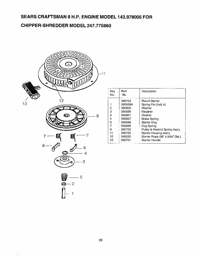
CHIPPER-SHREDDER MODEL 247.775860
-11
// 1213
8
Key Part DescriptionNo. No.
59O7041 590599A2 5906003 5906964 5906015 59O6976 5906987 5906998 59070011 59070512 59053513 590701
Recoil Starter
Spring Pin (Incl. 4)WasherRetainerWasher
Brake SpringStarter DogDog SpringPulley & Rewind Spring Ass'yStarter Housing Ass'yStarter Rope (98" x 9/64" Dia.)Starter Handle
q_--2
26
:orthe repairor replacementpartsyouneeddelivereddirectlyto yourhomeCall7 am - 7 pm, 7 daysa week
1-800-366 PART(1-800-366-7278)
Forin-homemajor.brandrepairserviceCall24 hoursa day,7 daysa week
1-8OO-4-REPAIR(1-800-473-7247)
Forthe locationofaSearsPartsandRepairCenterinyourarea
Call24 hours a day,7 daysa week
1-800-488-1222 mmmmmmmmmmmm
For informationon purchasinga SearsMaintenance Agreementor to inquire
about an existing Agreementcall 9 am - 5 prn, Monday-Saturday
1-800-827-6655
SEARSAmerica's Repair Specialists
Manual del Propietario
CRRFTSMRN8.0 HP
Capacidad de astillado de 3" de dia.metro
ASTILLADORA-DESMENUZADORA
Modelo No.
247.775860
PRECAUClON:
Antes de operareste equipolea y observetodas las reglase instrucciones
de seguridad
Sears, Roebuck and Co., Hoffman Estates, IL 60179, U.S.A.
Impreso en U.S.A. 770-0549M
Contenido
Informaci6n de garantfa
Pr_.cticas seguras de operaci6n
Ensamblado
Operaci6n
P#,gina Contenido P&gina
Mantenimiento 112
Servicio y Ajuste 143
Almacenamiento fuera de temporada 175
8
Garantfa de un afio para la astilladora-desmenuzadora Crafstman
Por un afio desde la fecha de compra cuando esta astilladora-desmenuzadora Craftsman sea mantenida, lubricada y puesta apunto de acuerdo con las instrucciones de operaci6n y mantenimiento en el manual del operario, Sears reparar& libre de costocualquier defecto de material o de mano de obra.
Esta garantfa excluye las cuchillas, cuchillas de la astilladora, desgranadoras, filtros, bujfas, bolsas colectoras y neumaticos, lascuales son partes desechables que se desgastan durante el uso normal.
Esta garantfa se aplica por 30 dfas solamente a partir de la fecha de compra, si la astilladora-desmenuzadora se usa para fines
comerciales o de alquiler.
EL SERVICIO DE GARANTIA ESTA DISPONIBLE EN CENTRO DE SERVICIO DE SEARS MAS CERCANO EN LOS ESTA-DOS UNIDOS. ESTA GARANTIA SE APLICA MIENTRAS EL PRODUCTO ESTE EN USO EN LOS ESTADOS UNIDOS.
Esta garantfa le otorga derechos legales especfficos y usted puede tambi_n tener otros derechos que varfan de Estado a Esta-do.
SEARS, ROEBUCK AND CO. DEPT. D817WA, HOFFMAN STATES, IL 60179
Estos accesorios estaban disponiblescuando la astilladora-desmenuzadora secompr5 originalmente. Estan tambi_n di-sponibles en la mayoria de las tiendasminoristas y centros de cat_.logo y servi-cio de Sears. La mayorfa de las tiendasde Sears pueden ordenar estas piezasde repuesto para usted con el nt3mero demodelo de su astilladora-desmenuza-dora.
Bujfa Filtro Aceite Recipiente Estabilizadorde aire de motor de gasolina
PRODUCTO ESPEClFICAClON
CABALLOS DE FUERZA: 8 H.P.
CAPACIDAD DEL CARTER: 26 oz. ACEITEDE MOTOR SAE 30
CAPACIDAD DEL TANQUE DECOMBUSTIBLE: 4 CUARTOS
(LIBRE DE PLOMO)
RESISTENCIA-BUJIA: (N4C)
SEPARACION .030
PRESION DEL NEUMATICO 24 PSI
Juego deenganche para
remolque
Nemero de modelo
N_mero de serie
Fecha de compra
Anote el nQmero de serie y la fecha de compra y manten-ga en un lugar seguro para referencia futura.
2
&&
Este simbolo indica instrucciones importantes de seguridad las cuales, si no se observan, pueden poner enpeligro la seguridad personal y/o la propiedad suya y de otras personas. Lea y observe todas las instrucciones deeste manual antes de intentar operar su astilladora-desmenuzadora a gasolina. La falla en cumplir con estas in-strucciones puede resultar en lesiones personales -- obedezca la advertencia.
PELIGRO:
Su astilladora-desmenuzadora fue fabricada para operarse de acuerdo con las reglas para unaoperaci6n segura en este manual. AI igual que con cualquier tipo de equipo motorizado, la faltade cuidado o error de parte del operador puede resultar en lesiones graves. Si usted viola estasreglas, puede causar lesiones graves a usted mismo y a otras personas.
ADVERTENClA: El escape del motor de este producto contiene substancias qu/micas conocidas por el Estado de Cal-ifornia como causantes de cancer, defectos de nacimiento u otras lesiones reproductivas.
1. OPERACION GENERAL• Lea cuidadosamente esta gufa del propietario en su total-
idad antes de intentar armar esta mAquina. Lea, compren-day observe todas las instrucciones en la mAquina yen elmanual(es) antes de la operaci6n. Guarde este manual enun lugar seguro para referencia futura y regular y para or-denar piezas de repuesto.
• Su astilladora-desmenuzadora es una herramienta pode-rosa y no un juguete. Por consiguiente sea extremada-mente precavido en todo momento. Su unidad ha sidodiseRada para desempeSar dos tareas; astillar y des-menuzar la vegetaci6n hallada en un patio normal. No lause para ningQn otro fin.
• Nunca permita que niSos menores de 16 aSos operen launidad. Los niSos de 16 aSos de edad y mayores debenoperar solamente bajo una supervisi6n paterna estrecha.
Debe permitirse operar la unidad a individuos respons-ables que est6n familiarizados con estas reglas de oper-aci6n segura, solamente.
• Mantenga el Area de operaci6n despejada de todas laspersonas, particularmente niSos peque5os y animalesdom_sticos. Apague el motor cuando estAn cerca de launidad. Mantenga el Area de trabajo limpia y despejada deramas u obstAculos que podrfan causar que se tropiece ocaiga.
• AI alimentar material a este equipo, sea extremadamentecuidadoso que no se incluyan piezas de metal, rocas, bo-tellas, latas u otros objetos extrahos. Podrfan resultar le-siones personales o daSos a la mAquina.
• Use siempre lentes de seguridad o antiparras de segu-ridad, durante la operaci6n y al efectuar ajustes o repara-clones, para proteger los ojos contra objetos extraSos quepueden ser despedidos por la mAquina.
• Use zapatos de trabajo resistentes, de suela aspera ypantalones y camisa ajustadas. Se recomiendan camisasy pantalones que cubran los brazos y las piernas y zapa-tos de puntera de acero. No use ropas holgadas ni joyas ysujete el cabello para que est_ por encima de los horn-bros. Pueden quedar atrapadas en las piezas m6viles.Nunca opere una unidad con los pies descalzos, sandaliaso zapatillas. AI alimentar material en la canaleta de la astil-ladora o en la tolva de la desmenuzadora, use guantes.
• Mientras est6 funcionando el motor, nunca coloque susmanos, pies o cualquier parte de su cuerpo dentro de latolva de la desmenuzadora, canaleta de la astilladora, ab-ertura de descarga ni cerca de cualquier pieza giratoria.Mant_ngase alejado en todo momento de la abertura dedescarga. Use un palo de diAmetro pequeSo y NO SUSMANOS, si fuera necesario empujar el material dentro dela canaleta de la astilladora o tolva de la desmenuzadora.
• Si por alguna raz6n es necesario destapar la toma de ali-mentaci6n o de la abertura de descarga o inspeccionar oreparar cualquier parte de la mAquina donde una piezam6vil puede entrar en contacto con su cuerpo o ropa,apague la mAquina, permita que se enfrfe, desconecte elcable de la bujfa de la bujfa y al6jelo de la bujfa antes deintentar destapar, inspeccionar o reparar.
= No opere la unidad mientras estA bajo la influencia del al-cohol o las drogas.
• La mAquina debe operarse sobre una superficie nivelada
solamente. Nunca opere su unidad sobre una superficieresbalosa, mojada, embarrada o helada. Mantenga suArea de trabajo limpia y libre de ramas u obstAculos quepueden causar que usted se tropiece y caiga. No se in-cline demasiado. El mantenerse firmemente parado y enequilibrio es esencial para prevenir accidentes.No permita que se acumule material procesado en el Areade descarga ya que esto prevendrA una descarga adecua-da y puede resultar en un contragolpe de la canaleta de laastilladora.
• Mantenga su rostro y cuerpo detrAs de la canaleta de laastilladora para evitar un rebote accidental del material.
• No transporte la maquina mientras el motor estA funciona-ndo.
• Si el mecanismo de corte golpea un objeto extrafio o si sumAquina comienza a emitir un ruido o vibraci6n no comt_n,apague inmediatamente el motor, desconecte el cable de
la bujia y mueva el cable alejado de la bujfa. Permita quela mAquina se detenga y efectt3e los pasos siguientes.
• Inspeccione por da5os.• Repare o reemplace las piezas daSadas.• Inspeccione por piezas flojas y ajuste para asegurar una
operaci6n segura continuada.
• NuncatratederetirarnivaciarlabolsacolectoracuandoelmotorestAfuncionando.Apagueelmotoryesperehas-taquelahelicesedetengacompletamente.Lah_licecon-tint_agirandoduranteunossegundosdespu6sdeapagarelmotor.NuncacoloqueningunapartedesucuerpoenelAreadelahelicehastaqueesteseguroquelahelicehadetenidosugiro.
• Elsilenciadory el motorsecalientany puedencausarquemaduras.Nolostoque.
• Nopermitaquehojasuotrosdesechosseacumulenso-breel silenciadordelmotor.Losdesechospodrfanen-cenderseycausarunincendio.
• Nuncatratededesmenuzaroastillarmaterialmasgrandequeelespecificadoenestemanual.Puederesultarenle-sionespersonalesodafiosa lamaquina.
• Nooperelamaquinasinelfiltroocubiertasobrelatomadeairedelcarburador,exceptoparaajustar.Laextracci6ndetalespartespuedecrearunriesgodeincendio.
• Uses61olosaccesoriosaprobadosparaestamaquinaporel fabricante.Lea,entienday observetodaslasinstruc-clonesprovistasconelaccesorioaprobado.
• SiocurrensituacionesquenoestAncubiertasperestemanual,useconcuidadoy buenjuicio.Paraasistenciaconsulteconsudistribuidor.
• Mantengaeldeflectordelacanaletadedescarga,lapuer-tadelacanaletadelaastilladoraytodaslasotrasguardasy mecanismosdeseguridadensulugary funcionandocorrectamente.
• Operelaunidadalaluzdeldfasolamente.Nooperelaun-idaddenocheoenAreasobscurasdondesuvisi6npuedaesta[,rrestringida.
2. NINOSPueden ocurrir accidentes trAgicos si el operador no estaalerta a la presencia de nifios pequefios. Los nifios se sient-en atrafdos a menudo a la astilladora-desmenuzadora y a laactividad de astillado y desmenuzado. Nunca suponga quelos nifios permaneceran donde usted los vio por t31timavez.• Mantenga a los nifios fuera del Area de trabajo y bajo la
mirada vigilante de un adulto responsable que no sea eloperador.
• Este alerta y apague la unidad si un nifio entra al Area.• Nunca permita que nifios menores de 16 aries de edad op-
eren la astilladora-desmenuzadora.
3. SERVIClOSea muy precavido al usar gasolina y otros combustibles. Sonextremadamente inflamables y los vapores son explosivos.
a. Almacene el combustible y aceite en recipientes apro-bados, alejados del calory de las llamas expuestas, fu-era del alcance de los nifios. Inspeccione y agreguecombustible antes de arrancar el motor. Nunca retire la
tapa de gasolina ni vierta combustible mientras el motoresta funcionando. Permita que el motor se enfrfe pordos minutos por Io menos antes de cargar combustible.
b. Vuelva a colocar la tapa de gasolina y limpie la gasoli-na derramada antes de arrancar el motor, ya quepuede causar un incendio o explosi6n.
c. Apague todos los cigarrillos, cigarros, pipas y otras fu-entes de encendido.
d. Nunca cargue combustible a la unidad bajo techo yaque los vapores inflamables se acumularAn en el Area.
e. Nunca almacene la mAquina ni el recipiente de com-bustible bajo techo donde haya llamas expuestas ochispas, tales como calentadores de agua caliente agas,, secadora de ropas u hornos.
• Nunca haga funcionar su mAquina en un Area cerrada yaque el escape del motor contiene mon6xido de carbono,que es un gas inodoro, ins/pido y envenenador mortal.
• Para reducir el riesgo de incendio, mantenga el motor y elsilenciador libre de hojas, grama, y otras acumulacionesde desechos. Limpie los derrames de combustible yaceite. Permita que la unidad se enfrie por 5 minutos porIo menos antes de arrancar.
• AsegQrese que la helice y todas las piezas m6viles estendetenidas, antes de limpiar, rep&rar o inspeccionar.Desconecte el cable de la buj/a y mantengalo alejado dela bujia para prevenir el arranque accidental. No use solu-ciones inflamables para limpiar el filtro de aire.
• Inspeccione la cuchilla y los tornillos de montaje del motora intervalos frecuentes, por un buen ajuste. Tambi6n in-speccione visualmente las cuchillas por desgaste y/odafios (por ej. doblada, agrietada). Reemplace con cuchil-las que cumplan con las especificaciones originales delequipo.
• Mantenga todas las tuercas, pernos y tornillos bien ajusta-dos para asegurarse que el equipo est_ en buenas condi-clones de trabajo.
• Nunca manipule los mecanismos de seguridad. Inspec-clone regularmente su operaci6n apropiada.
• Despu_s de golpear un objeto extrafio, apague inmediata-mente el motor, desconecte el cable de la buj/a de la bujia,e inspeccione completamente la unidad por dafios. Rep-are el dafio antes de arrancar y operar la unidad.
• No altere ni manipule la graduaci6n del regulador del mo-tor. El regulador controla la velocidad operativa maximadel motor. Es peligroso hacer funcionar el motor a una ve-Iocidad excesiva y causarA dafios al motor y a otras piezasm6viles de las maquinas.
4. SU RESPONSABILIDADRestrinja el uso de esta maquina motorizada a
,_ las personas que lean, comprendan y observenlas advertencias e instrucciones en este manual
y en la mAquina.
GUARDE ESTAS INSTRUCClONESPARA REFERENCIA FUTURA
Esta unidad estA equipada con un motor de combustion interna y no debe usarse en o cerca de tierras no mejoradascubiertas de bosques, matorrales, y/o hierbas, a menos que el sistema de escape est6 equipado con un supresorde chispas que cumpla con las leyes del estado o federales aplicables (de existir). Si se usa un supresor de chispasdebe ser mantenido en buenas condiciones de trabajo por el operador.
En el Estado de California Io indicado arriba es requerido por ley (Secci6n 4442 del C6digo de Recursos Pt_blicosde California). Otros Estados pueden tener leyes similares. Las leyes federales se aplican en las tierras federales.EstA disponible un supresor de chispas para el silenciador en su Centro de Servicio Autorizado Sears mas cercano(Vea la secci6n de PIEZAS DE REPUESTO de este manual).
4
\
\Tolva
Canaleta de descarga
Canaleta de laastilladora
IMPORTANTE: Esta unidad se despacha sin gasolina niaceite en el motor. Vea la secci6n de OPERACION de este
manual para las recomendaciones sobre combustible yaceite de motor adecuados, despues del ensamblado.
NOTA: Para determinar los lados izquierdo y derecho de suastilladora-desmenuzadora, parese detras de la unidad conel motor en posiciSn mas alejado de usted.
Su astilladora-desmenuzadora ha sido completamenteensamblada de fAbrica excepto por el conjunto de la tolva,canaleta de la astilladora, canaleta de descarga y la bolsacolectora.
Estas piezas se despachan sueltas en la caja. Se incluyentambien en la caja un par de gafas de seguridad y una botellade aceite.
1. EXTRAIGA LA ASTILLADORA-DESMENUZADORA DE LA CAJA
o Corte las esquinas de la caja.= Extraiga todas las inserciones de empaque.= Extraiga todas las piezas sueltas incluyendo el manual del
propietario. Vea la figura 1.• Ruede la astilladora-desmenuzadora fuera de la caja.• Antes de desechar la caja, asegQrese que todas las
piezas y la literatura hayan sido retiradas de la misma.
2. PIEZAS SUELTASa. Conjunto de la tolvab. Canaleta de descargac. Canaleta de la astilladorad. Bolsa colectorae. Botella de aceite
f. Gafas de seguridadg. Manual del Propietario (no se muestra en la figura 1)
Bolsa colectoraBotella de
aceite
Gafas de
seguridad
Figura 1
5
3. HERRAMIENTAS REQUERIDAS1. Llaves de 1/2" o ajustables2. Llaves de 7/16" o ajustables3. Embudo
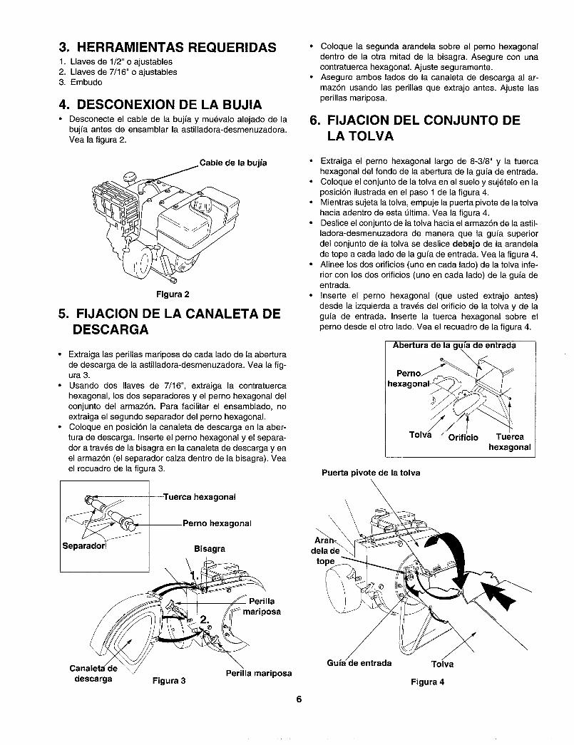
4. DESCONEXlON DE LA BUJIA• Desconecte el cable de la bujfa y mu_valo alejado de la
bujfa antes de ensamblar la astilladora-desmenuzadora.Vea la figura 2.
Cable de la bujia
Figura 2
5. FIJACION DE LA CANALETA DEDESCARGA
• Extraiga las perillas mariposa de cada lado de la aberturade descarga de la astilladora-desmenuzadora. Vea la fig-ura 3.
• Usando dos Ilaves de 7/16", extraiga la contratuercahexagonal, los dos separadores y el perno hexagonal delconjunto del armaz6n. Para facilitar el ensamblado, noextraiga el segundo separador del perno hexagonal.
• Coloque en posici6n la canaleta de descarga en la aber-tura de descarga. Inserte el perno hexagonal y el separa-dora traves de la bisagra en la canaleta de descarga y enel armaz6n (el separador calza dentro de la bisagra). Vea
el recuadro de la figura 3.
• Coloque la segunda arandela sobre el perno hexagonaldentro de la otra mitad de la bisagra. Asegure con unacontratuerca hexagonal. Ajuste seguramente.
• Asegure ambos lados de la canaleta de descarga al ar-maz6n usando las perillas que extrajo antes. Ajuste lasperillas mariposa.
6. FIJAClON DEL CONJUNTO DELA TOLVA
• Extraiga el perno hexagonal largo de 8-3/8" y la tuercahexagonal del fondo de la abertura de la gufa de entrada.
• Coloque el conjunto de la tolva en el suelo y suj_telo en laposici6n ilustrada en el paso 1 de la figura 4.
• Mientras sujeta la tolva, empuje la puerta pivote de la tolva
hacia adentro de esta _ltima. Vea la figura 4.• Deslice el conjunto de la tolva hacia el armaz6n de la astil-
ladora-desmenuzadora de manera que la gu_a superiordel conjunto de la tolva se deslice debajo de la arandelade tope a cada lado de la gufa de entrada. Vea la figura 4.
• Alinee los dos orificios (uno en cada lado) de la tolva infe-rior con los dos orificios (uno en cada lado) de la gufa deentrada.
• Inserte el perno hexagonal (que usted extrajo antes)desde la izquierda a trav_s del orificio de la tolva y de lagufa de entrada. Inserte la tuerca hexagonal sobre elperno desde el otro lado. Vea el recuadro de la figura 4.
Abertura de la guia de entrada
Puerta pivote de la tolva
Orificio Tuercahexagonal
Tuerca hexagonal
Perno hexagonal
Bisagra dela deto
Perilla
mariposa
\\
descarga Figura 3Perilla mariposa
entrada Tolva
Figura 4
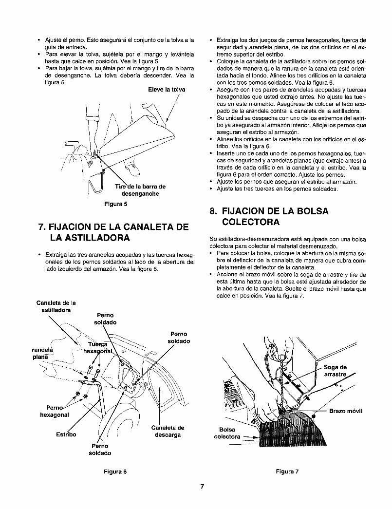
o
Ajuste el perno. Esto asegurar_, el conjunto de la tolva a lagufa de entrada.Para elevar la tolva, sujetela por el mango y lev_ntelahasta que calce en posici6n. Vea la figura 5.Para bajar la tolva, suj6tela por el mango y tire de la barrade desenganche. La tolva deberfa descender. Vea lafigura 5.
Eleve la tolva
/
la barra de
desenganche
Figura 5
7. FIJACION DE LA CANALETA DELA ASTILLADORA
• Extraiga las tres arandelas acopadas y las tuercas hexag-onales de los pernos soldados al lado de la abertura del
lado izquierdo del armaz6n. Vea la figura 6.
Pernosoldado
Pernosoldado
Pernchexagonal
Pernosoldado
Canaleta de
descarga
• Extraiga los dos juegos de pernos hexagonales, tuerca deseguridad y arandela plana, de los dos orificios en el ex-tremo superior del estribo.
• Coloque la canaleta de la astilladora sobre los pernos sol-dados de manera que la ranura en la canaleta est_ orien-tada hacia el fondo. Alinee los tres orificios en la canaleta
con los tres pernos soldados. Vea la figura 6.• Asegure con tres pares de arandelas acopadas y tuercas
hexagonales que usted extrajo antes. No ajuste las tuer-cas en este momento. Asegerese de colocar el lado aco-pado de la arandela contra la canaleta de la astilladora.
• Su unidad se despacha con uno de los extremos del estri-bo ya asegurado al armaz6n inferior. Afloje los pernos queaseguran el estribo al armaz6n.
• Alinee los orificios en la canaleta con los orificios en el es-
tribo. Vea la figura 6.• Inserte uno de cada uno de los pernos hexagonales, tuer-
cas de seguridad y arandelas planas (que extrajo antes) atrav_s de cada orificio en la canaleta y el estribo. Vea lafigura 6 para el orden correcto. Ajuste los pernos.
° Ajuste los pernos que aseguran el estribo al armaz6n.• Ajuste las tres tuercas en los pernos soldados.
8. FIJACION DE LA BOLSACOLECTORA
Su astilladora-desmenuzadora est_ equipada con una bolsacolectora para colectar el material desmenuzado.• Para colocar la bolsa, coloque la abertura de la misma so-
bre el deflector de la canaleta de manera que cubra com-pletamente el deflector de la canaleta.
• Accione el brazo m6vil sobre la soga de arrastre y tire deesta _ltima hasta que la bolsa est_ ajustada alrededor dela abertura de la canaleta. Suelte el brazo m6vil hasta quecalce en posici6n. Vea la figura 7.
a de
_vil
Bolsacolectora
Figura 6 Figura 7
7
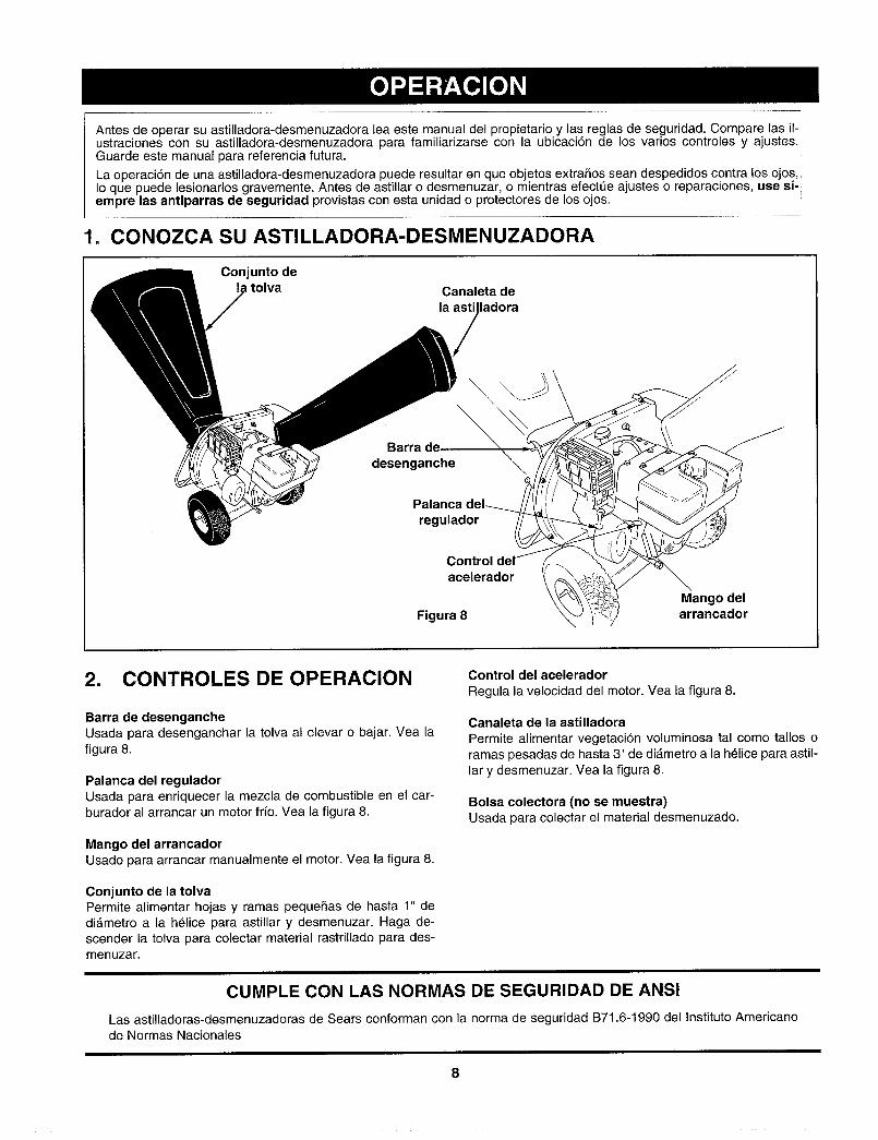
Antes de operar su astilladora-desmenuzadora lea este manual del propietario y las reglas de seguridad. Compare las il- Iustraciones con su astilladora-desmenuzadora para familiarizarse con la ubicaci6n de los varios controles y ajustes.!Guarde este manual para referencia futura.
La operaci6n de una astilladora-desmenuzadora puede resultar en que objetos extraSos sean despedidos contra los ojos, JIo que puede lesionarlos gravemente. Antes de astillar o desmenuzar, o mlentras efectQe ajustes o reparaciones, use si-empre las antiparras de seguridad provistas con esta unidad o protectores de los ojos.
1. CONOZCA SU ASTILLADORA-DESMENUZADORA
Conjunto detolva Canaleta de
la asti ladora
Barra de _ _-_desenganche
Palanca
regulador
Controlacelerador
Figura 8
2. CONTROLES DE OPERACION
Barra de desengancheUsada para desenganchar la tolva al elevar o bajar. Vea la
figura 8.
Palanca del reguladorUsada para enriquecer la mezcla de combustible en el car-burador al arrancar un motor frio. Vea la figura 8.
Mango del arrancadorUsado para arrancar manualmente el motor, Yea la figura 8.
Control del acelerador
Regula la velocidad del motor. Vea la figura 8.
Canaleta de la astilladora
Permite alimentar vegetaci6n voluminosa tal como tallos oramas pesadas de hasta 3" de diAmetro a la h61ice para astil-lar y desmenuzar. Vea la figura 8.
Bolsa colectora (no se muestra)Usada para colectar el material desmenuzado.
Conjunto de la tolvaPermite alimentar hojas y ramas pequeSas de hasta 1" dedi_.metro a la h_lice para astillar y desmenuzar. Haga de-scender la tolva para colectar material rastrillado para des-menuzar.
CUMPLE CON LAS NORMAS DE SEGURIDAD DE ANSI
Las astilladoras-desmenuzadoras de Sears cenforman con la norma de seguridad B71.6-1990 del Instituto Americanode Normas Nacionales
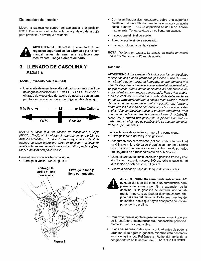
Detencibn del motor
Mueva la palanca de control del acelerador a la posici6nSTOP. Desconecte el cable de la bujia y alejelo de la bujfapara prevenir un arranque accidental.
_ ADVERTENCIA: Refierase nuevamente a lasreglas de seguridad en las pdginas 3 y 4 de estemanual, antes de usar esta astilladora-des-
menuzadora. Tenga siempre cuidado.
3. LLENADO DE GASOLINA YACEITE
Aceite (Envasado con la unidad)
Use aceite detergente de alta calidad solamente clasifica-do segL_n la clasificaci6n API de SF, SG o SH. Seleccioneel grado de viscosidad del aceite de acuerdo con su tem-peratura esperada de operaci6n. Siga la tabla de abajo.
Mds Frio _ 32° _ Mds Caliente
NOTA: A pesar que los aceites de viscosidad m#ltiple(5W30, 10W30, etc.) mejoran el arranque en tiempo fr[o, losmismos resultaran en un consumo mayor de combustiblecuando se usan sobre los 32-°F. Inspeccione su nivel deaceite mas frecuentemente para evitar da#os posibles al mo-tor al funcionar con poco aceite.
Llene el motor con aceite como sigue.• Extraiga la varilla. Vea la figura 9.
Extraiga lavarilla y Ilene
con aceite
Extraiga la tapa yIlene con gasolina
\
Figura 9
• Con la astilladora-desmenuzadora sobre una superficienivelada, use un embudo para Ilenar el motor con aceitehasta la marca FULL. La capacidad es de 26 oz. aproxi-madamente. Tenga cuidado en no Ilenar en exceso.
• Inspeccione el nivel de aceite.
• Agregue aceite si fuera necesario.
• Vuelva a colocar la varilla y ajuste.
NOTA: No Ilene en exceso. La botella de aceite envasadacon la unidad contiene 26 oz. de aceite.
Gasolina
ADVERTENCIA:La experiencia indica que los combustiblesmezclados con alcohol (llamados gasohol o el uso de etanolo metanol) pueden atraer la humedad, Io que conduce a laseparaciSn y formaciSn de #cido durante el almacenamiento.El gas acfdico puede daSar el sistema de combustible del
motor mientras permanezca almacenado. Para evitar proble-mas con el motor, el sistema de combustible debe vaciarse
antes de almacenar durante 30 dfas o mas. Drene el tanquede combustible, arranque el motor y permita que funcionehasta que las tuberfas de combustible y el carburador est#nvacfos. Use combustible fresco la prSxima temporada. Parainformaci6n adicional vea las instrucciones de ALMACE-
NAMIENTO. Nunca use productos limpiadores de motor ocarburador en el tanque de combustible ya que pueden ocur-rir da_os permanentes.
Llene el tanque de gasolina con gasolina como sigue.• Extraiga la tapa del tanque de gasolina.
• AsegQrese que el recipiente (del cual vertera la gasolina)este Iimpio y libre de 6xido o partfculas extraSas. Nuncause gasolina que pueda estar rancia despu_s de periodosprolongados de almacenamiento en el recipiente.
• Llene el tanque de combustible con gasolina fresca y librede plomo, para automotores. NO use etilo ni gasolina dealto fndice de octano. Vea la figura 9.
• Vuelva a colocar la tapa del tanque de combustible.
_ ADVERTENCIA: No Ilene hasta sobrepasar 1/2pulgada del tope del tanque de combustible paraprevenir derrames y permitir la expansi6n de lagasolina. Si la gasolina se derrama accidental-mente, mueva la astilladora-desmenuzadora ale-jada del area del derrame. Evite crear fuentes deencendido hasta que hayan desaparecido los va-pores de la gasolina.
Para evitar que se agote la gasolina mientras est_ operan-do la astilladora-desmenuzadora, inspeccione peri6dica-mente el nivel de combustible.
Puede ser necesario destapar la unidad antes de poderlaarrancar, si se agota la gasolina mientras est,. desmenu-zando o astillando. Refi_rase a "Retiro del tamiz de ladesgranadora" en la secci6n de SERVlCIO Y AJUSTES.
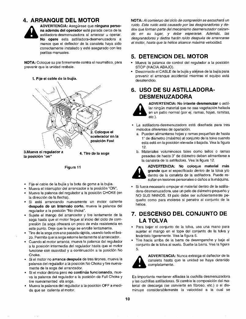
4. ARRANQUE DEL MOTOR
ADVERTENClA: AsegL_rese que ninguna perso-na ademds del operador est_ parada cerca de laastilladora-desmenuzadora al arrancar u operar.
No opere esta astilladora-desmenuzadora amenos que el deflector de la canaleta haya sidocorrectamente instalado y est_ asegurado con lasperillas manuales.
NOTA: Coloque su pie firmemente contra el neum_,tico, paraprevenir que la unidad resbale.
1. Fije el cable de la bujfa.\
3.Mueva el regulador ala posicibn "on"
Inla\ posicibn Fast
\\
4. Tire de la soga
Figura 1!
• Fije el cable de la buj{a y la bota de goma a la buj_a.• Mueva el interruptor del arrancador a la posici6n "ON".• Mueva la palanca del regulador a la posici6n CHOKE (en
la direcci6n de la flecha).• Si est_ arrancando nuevamente un motor caliente
despu_s de un intervalo corto, mueva la palanca delregulador a la posici6n "No choke".
• Sujete el mango del arrancador y tire lentamente de lasoga hasta que el motor Ilegue al inicio del ciclo de com-presi6n (la soga ofrecera un poco de m&s resistencia eneste punto. Deje que la soga se enrolle lentamente.
• Tire de la soga con una pasada r&pida, usando todo el bra-zo. Permita que la soga retorne lentamente al arrancador.
• Cuando el motor arranca, mueva la palanca del regulador
a la posici6n intermedia del regulador hasta que el motorfuncione con suavidad y a continuaci6n a la posici6n NoChoke.
• Si el motor no arranca despu_s de tres tirones, mueva lapalanca del regulador a la posici6n No Choke y tire nueva-mente de la soga del arrancador.
• Si el motor detona pero no continda funcionando, mue-va la palanca del regulador a la posici6n de Full Choke ytire nuevamented ela soga.
• Mueva la palanca del regulador a la posici6n OFF a medi-daque se calienta el motor.
10
NOTA: AI comienzo del ciclo de compresi6n se escuchar_ unruido. Este ruido est_ causado por las desgranadoras y de-dos que forman parte del mecanismo desmenuzador calzan-do en su lugar, y debe esperarse. Adem_s, lasdesgranadoras y dedos har_n ruido despu6s de arrancarseel motor, hasta que la h_lice alcance m_xima velocidad.
5. DETENCION DEL MOTOR• Mueva la palanca de control del regulador a la posici6n
STOP (HACIA ABAJO).• Desconecte el CABLE de la buj{a y al_jese de la buj/a para
prevenir el arranque accidental mientras el equipo est_desatendido.
6. USO DE SU ASTILLADORA-DESMENUZADORA
ADVERTENCIA: No intente desmenuzar o astil-lar ningt_n material que no sea vegetaci6n halladaen un patio normal (por ej. ramas, hojas, ramitas,etc.).
• La astilladora-desmenuzadora est& diseSada para tresmetodos diferentes de operaci6n.a. Pueden alimentarse hojas y ramas pequeSas de hasta
1" de di_metro (m_ximo) al conjunto de la tolva cuandoesta est_ en la posici6n elevada o bajada. Vea la figura12.
b. Materiales voluminosos tales como tallos o ramas
pesadas de hasta 3" de diametro deben alimentarse ala canaleta de la astilladora. Vea la figura 12.
ADVERTENCIA: No coloque material mdsgrande que el especificado dentro de la tolva y/odentro de la canaleta de la astilladora. Puede re-
sultar en lesiones personales o daSos a la m_.quina.
Si fuera necesario empujar el material dentro de la astilla-dora-desmenuzadora, use un palo de di&metro pequefio yNO SUS MANOS. El palo debe ser suficientemente pe-
que5o como para molerse si penetra al conjunto de lah_lice.
7. DESCENSO DEL CONJUNTO DELA TOLVA
• Para bajar el conjunto de la tolva, use una mano parasujetar el mango en el tope del conjunto de la tolva ylev_ntelo ligeramente. Vea la figura 5.
• Tire hacia arriba de la barra de desenganche y baje el
conjunto de la tolva al suelo. Suelte la barra. Vea la figura5.
_ DVERTENCIA: Nunca extraiga el deflector de lacanaleta hasta que la unidad se haya detenidocompletamente.
Es importante mantener afiladas la cuchilla desmenuzadoray las cuchillas astilladoras. Si cambia la composici6n del ma-terial de descarga (se convierte en fibroso, etc.) o si dis-minuye considerablemente la velocidad a la cual se
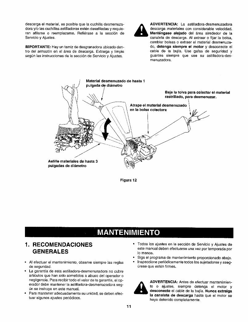
descargaelmaterial,esposiblequelacuchilladesmenuza-doray/olascuchillasastilladorasest_ndesafiladasyrequie-ranafilarseo reemplazarse.Refierasea la secci6ndeServicioyAjustes.
IMPORTANTE:Hayuntamizdedesgranadoraubicadoden-trodelarmaz6nenel_.readedescarga.Extraigay limpieseg6nlasinstruccionesdelasecci6ndeServicioyAjustes.
ADVERTENClA: La astilladora-desmenuzadora
descarga materiales con considerable velocidad.Mantdngase alejado del _rea alrededor de lacanaleta de descarga. AI extraer o fijar la bolsa,cambiar bolsas o extraer el material desmenuza-
do, detenga siempre el motor y desconecte elcable de la bujfa. Use gafas de seguridad yguantes siempre que use su astilladora-des-menuzadora.
Material desmenuzado de hasta 1
pulgada de didmetro
/ Baje la tolva para colectar el materialrastrillado, para desmenuzar.
Atrape el material desmenuzado \en la bolsa colectora
Astille materiales de hasta 3
pulgadas de didmetro
Figura 12
1. RECOMENDACIONESGENERALES
° AI efectuar el mantenimiento, observe siempre las reglasde seguridad.
° La garantfa de esta astiltadora-desmenuzadora no cubreartfculos que han sido sometidos a abuso del operador onegligencia. Para recibir todo el valor de la garantfa, el op-erador debe mantener la astilladora-desmenuzadora seg-5n se instruye en este manual.
• Para mantener adecuadamente su unidad, se deben efec-tuar algunos ajustes peri6dicos.
° Todos los ajustes en la secci6n de Servicio y Ajustes deeste manual deben efectuarse una vez por temporada porIo menos.
° Siga el programa de mantenimiento proporcionado abajo.° Inspeccione peri6dicamente todos los sujetadores y aseg-
t_rese que esten firmes.
11
_ ADVERTENCIA: Antes de efectuar mantenimien-to o ajustes, siempre detenga el motor ydesconecte el cable de la bujfa. Nunca extraigala canaleta de descarga hasta que el motor sehaya detenido completamente.
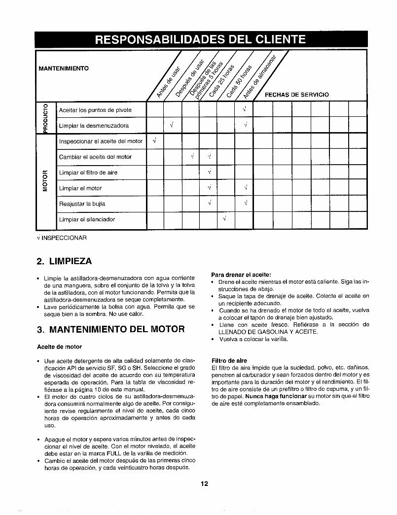
MANTENIMIENTO @
IO Aceitar los puntos de pivote _/O
a
O Limpiar la desmenuzadora */ _/n
Inspeccionar el aceite del motor _/
Cambiar el aceite del motor _J _/
Limpiar el filtro de aire _/
0 Limpiar el motor _/
Reajustar la bujia _J _/
Limpiar el silenciador 4
_/INSPECCIONAR
f FECHAS DE SERVICIO
2. LIMPIEZA
• Limpie la astilladora-desmenuzadora con agua corrientede una manguera, sobre el conjunto de la tolva y la tolvade la astilladora, con el motor funcionando. Permita que laastilladora-desmenuzadora se seque completamente.
• Lave peri6dicamente la bolsa con agua. Permita que seseque bien a la sombra. No use calor.
3. MANTENIMIENTO DEL MOTOR
Aceite de motor
• Use aceite detergente de alta calidad solamente de clas-ificaci6n API de servicio SF, SG o SH. Seleccione el gradode viscosidad del aceite de acuerdo con su temperatura
esperada de operaci6n. Para la tabla de viscosidad re-fi6rase a la pAgina 10 de este manual.
• El motor de cuatro ciclos de su astilladora-desmenuza-
dora consumirA normalmente algo de aceite. Por consigu-iente revise regularmente el nivel de aceite, cada cincohoras de operaci6n aproximadamente y antes de cadaUSO.
• Apague el motor y espere varios minutos antes de inspec-cionar el nivel de aceite. Con el motor nivelado, el aceitedebe estar en la marca FULL de la varilla de medici6n.
• Cambie el aceite del motor despues de las primeras cincohoras de operaci6n, y cada veinticuatro horas despues.
12
Para drenar el aceite:
• Drene el aceite mientras el motor est,. caliente. Siga las in-strucciones de abajo.
• Saque la tapa de drenaje de aceite. Colecte el aceite enun recipiente adecuado.
• Cuando se ha drenado el motor de todo el aceite, vuelva
a colocar el tap6n de drenaje bien ajustado.• Llene con aceite fresco. Refierase a la secci6n de
LLENADO DE GASOLINA Y ACEITE.• Vuelva a colocar la varilla.
Filtro de aire
El filtro de aire impide que la suciedad, polvo, etc. dafiinos,
penetren al carburador y sean forzados dentro del motor yesimportante para la duraci6n del motor y el rendimiento. El fil-tro de aire consiste de un prefiltro o filtro de espuma, y un ill-tro de papel. Nunca haga funcionar su motor sin que el filtrode aire est_ completamente ensamblado.
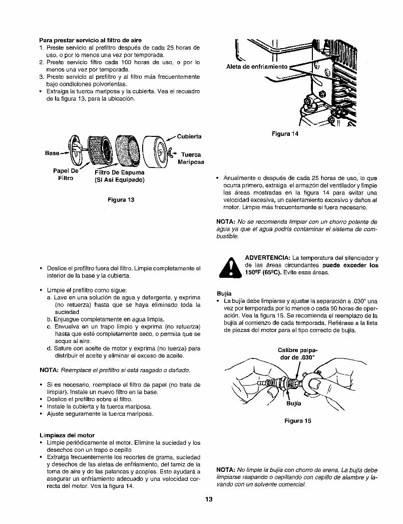
Para prestar servicio al filtro de aire1. Preste servicio al prefiltro despues de cada 25 horas de
uso, o por Io menos una vez por temporada.2. Preste servicio filtro cada 100 horas de uso, o por Io
menos una vez por temporada.3. Preste servicio al prefiltro y al filtro m_s frecuentemente
bajo condiciones polvorientas.• Extraiga la tuerca mariposa y la cubierta. Vea el recuadro
de la figura 13, para la ubicaci6n.
lAleta de enfriamiento
Base
Papel DeFiltro
.f Cubierta
_'_ Tuerca
Mariposa
Filtro De Espuma(Si Asi Equipado)
Figura 13
Figura 14
Anualmente o despu_s de cada 25 horas de uso, Io que
ocurra primero, extraiga el armaz6n del ventilador y limpietas areas mostradas en la figura 14 para evitar unavelocidad excesiva, un calentamiento excesivo y da5os almotor. Limpie m_s frecuentemente si fuera necesario.
NOTA: No se recomienda limpiar con un chorro potente deagua ya que el agua podr[a contaminar el sistema de com-bustible.
• Deslice el prefiltro fuera del filtro. Limpie completamente elinterior de la base y la cubierta.
Limpie el prefiltro como sigue:a. Lave en una soluci6n de agua y detergente, y exprima
(no retuerza) hasta que se haya eliminado toda lasuciedad
b. Enjuague completamente en agua limpia.c. Envuelva en un trapo limpio y exprima (no retuerza)
hasta que est_ completamente seco, o permita que seseque al aire.
d. Sature con aceite de motor y exprima (no tuerza) paradistribuir el aceite y eliminar el exceso de aceite.
NOTA: Reemplace el prefiltro siesta rasgado o da_ado.
• Si es necesario, reemplace el filtro de papel (no trate delimpiar). Instale un nuevo filtro en la base.
• Deslice el prefiltro sobre el filtro.• Instale la cubierta y la tuerca mariposa.• Ajuste seguramente la tuerca mariposa.
Limpieza del motor• Limpie peri6dicamente el motor. Elimine la suciedad y los
desechos con un trapo o cepillo• Extraiga frecuentemente los recortes de grama, suciedad
y desechos de las aletas de enfriamiento, del tamiz de latoma de aire y de las palancas y acoples. Esto ayudar_ aasegurar un enfriamiento adecuado y una velocidad cor-recta del motor. Vea la figura 14.
ADVERTENCIA: La temperatura del silenciador yde las Areas circundantes puede exceder los150-°F (65-°0). Evite esas _.reas.
Bujfa
• La bujfa debe limpiarse y ajustar la separaci6n a .030" unavez por temporada por Io menos o cada 50 horas de oper-aci6n. Vea la figura 15. Se recomienda el reemplazo de labujfa al comienzo de cada temporada. Refi6rase a la listade piezas del motor para el tipo correcto de bujfa.
Calibre palpa-dor de .030"
Bujia
Figura 15
NOTA: No limpie la bujfa con chorro de arena. La bujfa debelimpiarse raspando o cepillando con cepillo de alambre y la-vando con un solvente comerciaL
13
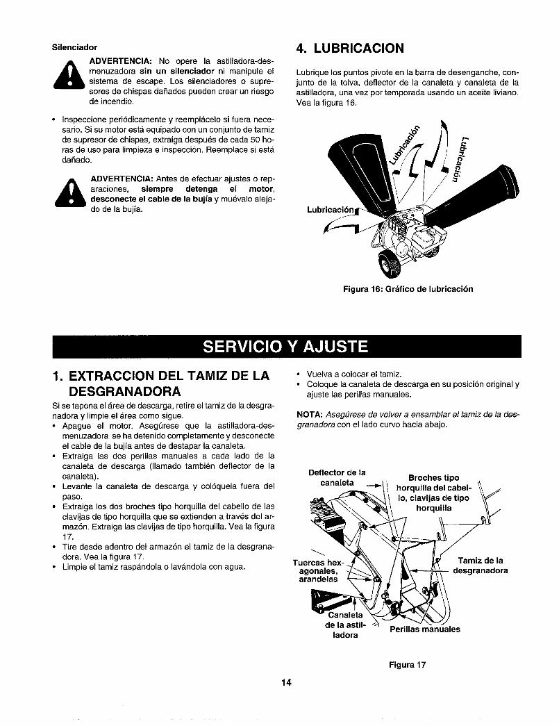
Silenciador
_i ADVERTENClA: No opere la astilladora-des-menuzadora sin un silenciador ni manipule elsistema de escape. Los silenciadores o supre-sores de chispas dafiados pueden crear un riesgode incendio.
Inspeccione peribdicamente y reempl_celo si fuera nece-sario. Si su motor est,. equipado con un conjunto de tamizde supresor de chispas, extraiga despu_s de cada 50 ho-ras de uso para limpieza e inspecci6n. Reemplace si estadafiado.
_i DVERTENCIA: Antes de efectuar ajustes o rep-araciones, siempre detenga el motor,desconecte el cable de la bujfa y muevalo aleja-do de la bujfa.
4. LUBRICACION
Lubrique los puntos pivote en la barra de desenganche, con-junto de la toIva, deflector de la canaleta y canaleta de laastilladora, una vez por temporada usando un aceite liviano.Vea la figura 16.
Lubricacion
Figura 16: Grafico de lubricaci6n
1. EXTRACCION DEL TAMIZ DE LADESGRANADORA
Si se tapona el area de descarga, retire el tamiz de la desgra-nadora y limpie el _rea como sigue.• Apague el motor. Asegerese que la astilladora-des-
menuzadora se ha detenido completamente y desconecteel cable de la bujfa antes de destapar la canaleta.
• Extraiga las dos perillas manuales a cada lado de lacanaleta de descarga (llamado tambi_n deflector de lacanaleta).
• Levante la canaleta de descarga y col6quela fuera del
paso.• Extraiga los dos broches tipo horquilla del cabello de las
clavijas de tipo horquilla que se extienden a trav_s del ar-maz6n. Extraiga las clavijas de tipo horquilla. Vea la figura17.
• Tire desde adentro del armaz6n el tamiz de la desgrana-dora. Vea la figura 17.
• Limpie el tamiz rasp_ndola o lav_ndola con agua.
• Vuelva a colocar el tamiz.
• Coloque la canaleta de descarga en su posici6n original yajuste las perillas manuales.
NOTA: AsegOrese de volver a ensamblar el tamiz de la des-granadora con el lado curvo hacia abajo.
Deflector de laBroches tipocanaleta /
! horquilladelcabel-Io, clavijas de tipo
horquilla
Tuercasagonales,arandelas
Tamiz de ladesgranadora
Canaletade la astil-
ladoraPerillas manuales
14
Figura 17
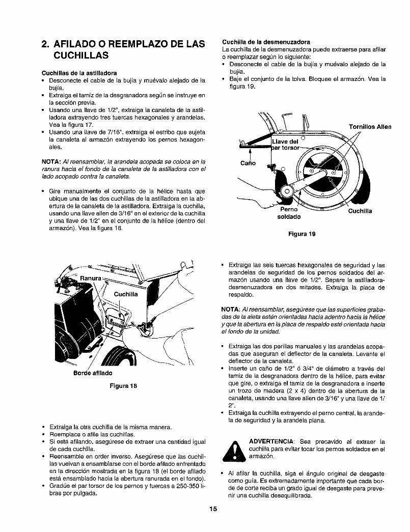
2. AFILADO O REEMPLAZO DE LASCUCHILLAS
Cuchillas de la astilladora
• Desconecte el cable de la bujfa y muevalo alejado de labujfa.
• Extraiga el tamiz de la desgranadera segt_n se instruye enla secci6n previa.
° Usando una Ilave de 1/2", extraiga la canaleta de la astil-ladora extrayendo tres tuercas hexagonales y arandelas.Vea la figura 17.
° Usando una Ilave de 7/16", extraiga el estribo que sujetala canaleta al armaz6n extrayendo los pemos hexagon-ales.
NOTA: AI reensamblar, la arandela acopada se coloca en laranura hacia el fondo de la canaleta de la astilladora con el
lado acopado contra la canaleta.
Gire manualmente el conjunto de la h61ice hasta queubique una de las dos cuchillas de la astilladora en la ab-ertura de la canaleta de la astilladora. Extraiga la cuchilla,usando una Ilave allen de 3/1 6" en el exterior de la cuchilla
y una Ilave de 1/2" en el conjunto de la h_lice (dentro delarmaz6n). Vea la figura 18.
Cuchilla de la desmenuzadora
La cuchilla de la desmenuzadora puede extraerse para afilaro reemplazar segL_n Io siguiente:• Desconecte el cable de la bujia y muevalo alejado de la
bujia.
• Baje el cenjunto de la telva. Bloquee el armaz6n. Vea lafigura 19.
Tornillos Allen
Caho
Perno Cuchillasoldado
Figura 19
Borde afilado
Figura 18
• Extraiga la otra cuchilla de la misma manera.• Reemplace o afile las cuchillas.• Siesta afilando, aseg_rese de extraer una cantidad igual
de cada cuchilla.
• Reensamble en order inverso. Asegt_rese que las cuchil-las vuetvan a ensamblarse con el borde afilado enfrentado
en la direcci6n mostrada en la figura 18 (el borde afiladoesta ensamblado hacia la abertura ranurada en el fondo).
• GradQe el par torsor de los pernos y tuercas a 250-350 li-bras por pulgada.
Extraiga las seis tuercas hexagonales de seguridad y lasarandelas de seguridad de los pernos soldados del ar-maz6n usando una Ilave de 1/2". Separe la astilladora-desmenuzadora en dos mitades. Extraiga la placa derespaldo.
NOTA: AI reensamblar, aseg#rese que las superficies graba-das de la aleta est6n orientadas hacia adentro hacia la h#lice
y que la abertura en la placa de respaldo est# orientada haciael fondo de la unidad.
• Extraiga las dos perillas manuales y las arandelas acopa-das que aseguran el deflector de la canaleta. Levante eldeflector de la canaleta.
• Inserte un caSo de 1/2" 6 3/4" de di_.metro a trav6s del
tamiz de la desgranadora dentro de la h_lice, para evitarque gire, o extraiga el tamiz de la desgranadora e inserteun trozo de madera (2 x 4) dentro de la abertura de lacanaleta, usando una Ilave allen de 3/16" y una llave de 1/2".
• Extraiga la cuchilla extrayendo el perno central, la arande-la de seguridad y la arandela ptana.
15
_) ADVERTENCIA: Sea precavido al extraer lacuchilla para evitar tocar los pernos soldados en elarmaz6n.
AI afilar la cuchilla, siga el &ngulo original de desgastecomo gufa. Es extremadamente importante que cada bor-de de corte reciba un grade igual de desgaste para preve-nir una cuchilla desequilibrada.
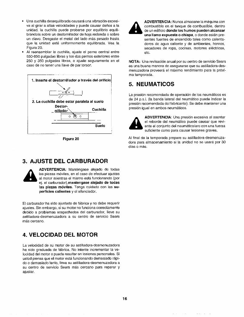
• Unacuchilladesequilibradacausaraunavibraci6nexcesi-vaalgiraraaltasvelocidadesy puedecausardafiosa launidad,lacuchillapuedeprobarseporequilibrioequili-br_ndolasobreundestornilladordehojaredondaosobreunclavo.Desgasteelmetaldelladomaspesadohastaquela unidadest6uniformementeequilibrada.YealaFigura20.
• AIreensamblarlacuchilla,ajusteel pernocentralentre550-650pulgadaslibrasy losdospernosexterioresentre250y 350pulgadaslibras,o ajusteseguramenteenelcasodenotenerunaIlavedepartorsor.
1.Inserte el destornillador a travds del orificio
d/
2. La cuchilla debe estar paralela al sueloDestor-nilladorX.. Cuchilla
-- 1 o_'_) 0 i_
Suelo
Figura 20
ADVERTENCIA: Nunca almacene la m_.quina concombustible en el tanque de combustible, dentrode un edificio donde los humos pueden alcanzaruna llama expuesta o chispa, o donde esten pre-sentes fuentes de encendido tales como calenta-
dores de agua caliente y de ambientes, hornos,secadores de ropa, cocinas, motores el6ctricos,etc.
NOTA" Una revisaci6n anual por su centro de servicio Searses una buena manera de asegurarse que su astilladora-des-menuzadora proveer_, el m_.ximo rendimiento para la pr6xi-ma temporada.
5. NEUMATICOS
La presi6n recomendada de operaci6n de los neum_.ticos esde 24 p.s.i. (la banda lateral del neumAtico puede indicar lapresi6n recomendada del fabricante). Se debe mantener unapresi6n igual en ambos neum_ticos.
ADVERTENCIA: Una presi6n excesiva al asentarel reborde del neum_ttico puede causar que revi-ente el conjunto del neumAtico/aro con una fuerzasuficiente como para causar lesiones graves.
AI final de la temporada prepare su astilladora-desmenuza-dora para almacenamiento si la unidad no se usarA por 30dfas o m#ts.
3. AJUSTE DEL CARBURADOR
,_ ADVERTENClA: Mant6ngase alejado de todaslas piezas m6viles, en el caso de efectuar ajustesal motor mientras el mismo esta. funcionando (porej. el carburador),mantengase alejado de todaslas piezas m6viles. Tenga cuidado con las su-perficies calientes y el silenciador.
El carburador ha sido ajustado de f_tbrica y no debe requerirajustes. Sin embargo, si su motor no funciona correctamentedebido a problemas sospechados del carburador, Ileve suastilladora-desmenuzadora a su centro de servicio Searsm_s cercano.
4. VELOCIDAD DEL MOTOR
La velocidad de su motor de su astilladora-desmenuzadora
ha sido graduada de fabrica. No intente incrementar la ve-Iocidad del motor o puede resultar en lesiones personales. Siusted piensa que el motor estA funcionando demasiado r_.pi-do o demasiado lento, Ileve su astilladora-desmenuzadora a
su centro de servicio Sears ma.s cercano para reparar yajustar.
16
_ ADVERTENCIA: Nunca almacene la mAquina concombustible en el tanque de combustible, dentrode un edificio donde los humos pueden alcanzar
una llama expuesta o chispa, o donde est6n pre-sentes fuentes de encendido tales como calenta-
dores de agua caliente y de ambientes, homos,secadores de ropa, cocinas, motores electricos,etc.
Una revici6n anual por su centro de servicio Sears es unabuena manera de asegurarse que su astilladora-desmenuza-dora proveerA el mAximo rendimiento para la pr6xima tempo-rada.
1. ASTILLADORA-DESMENUZADORA
• Limpie completamente la astilladora-desmenuzadora• Frote la unidad con un trapo aceitado para prevenir la ox-
idaci6n (use un aceite liviano o siliconas)
2. MOTOR
IMPORTANTE: Es importante evitar prevenir que se formendep6sitos de goma en piezas esenciales del sistema talescomo el carburador, el filtro de combustible, la manguera de
combustible o el tanque, durante el almacenamiento. Tam-bien, la experiencia indica que los combustibles mezcladoscon alcohol (llamados gasohol o que usan etanol o metanol)pueden atraer la humedad Io que resulta enla separaci6n y formaci6n de acidos durante el almace-namiento. El gas acidico puede dafiar el sistema de combus-tible del motor mientras esta en almacenamiento.
• Drene el tanque de combustible.• Arranque el motor y permita que funcione hasta que las tu-
berias de combustible y el carburador est6n vacios.• Drene el carburador presionando hacia arriba la taza de
drenaje la que estA ubicada debajo del carburador. Vea lafigura 21.
• Nunca use productos limpiadores del motor o del carbura-dor en el tanque de combustible ya que puede ocurrir undafio permanente.
• Use combustible fresco la pr6xima temporada.
NOTA: El estabilizador de combustible es una alternativa
aceptable para miniminizar la formaciSn de dep6sitos degoma del combustible durante el almacenamiento.• Agregue el estabilizador a la gasolina en el tanque de
combustible o recipiente de almacenamiento.• Siempre siga la proporci6n de mezcla de combustible in-
dicada en el recipiente del estabilizador.• Despu_s de agregar estabilizador haga funcionar el motor
durante 10 minutos por Io menos, para permitir que el es-tabilizador Ilegue el carburador.
• No drene el tanque de combustible ni el carburador si usael estabilizador de combustible. Drene todo el aceite del
carter (esto debe hacerse despues que ha funcionado elmotor y estA todavia caliente) y Ilene el carter con aceitefresco.
• Si usted ha drenado el tanque de combustible, proteja elinterior del motor como sigue.
• Extraiga la buj[a, vierta 1/2 aproximadamente (una cucha-rada de t_) de aceite de motor, dentro del cilindro e intentearrancar lentamente para distribuir el aceite.
• Vuelva a colocar la bujfa.
3. OTRO• No almacene gasolina de una temporada a la otra.• Reemplace su recipiente de gasolina si comienza a oxi-
darse. La oxidaci6n y/o la suciedad en su gasolinacausarA problemas. Almacene la unidad en un Area lim-pia, seca. No almacene cerca de materiales corrosivos, talcomo fertilizantes.
NOTA: Si se almacena en una casilla no ventilada o de met-
al, asegOrese de proteger el equipo contra el 6xido recu-bri&ndolo con un aceite fiviano o siliconas.
17
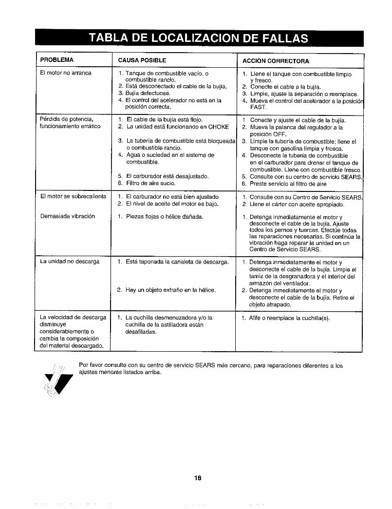
PROBLEMA CAUSA POSIBLE ACCION CORRECTORA
El motor no arranca 1. 1.
2.
3.4.
Perdida de potencia,funcionamiento err_.tico
El motor se sobrecalienta
Demasiada vibraci6n
La unidad no descarga
La velocidad de descargadisminuyeconsiderablemente o
cambia la composici6ndel material descargado.
Tanque de combustible vacfo, ocombustible rancio.Est_ desconectado el cable de la bujfa.Bujfa defectuosa.El control del acelerador no estA en laposici6n correcta.
1. El cable de la bujfa est& flojo.2. La unidad estA funcionando en CHOKE
3. La tuberfa de combustible est,. bloqueadao combustible rancio.
4. Agua o suciedad en el sistema decombustible.
5. El carburador est,. desajustado.6. Filtro de aire sucio.
1. El carburador no est,. bien ajustado2. El nivel de aceite del motor es bajo.
1. Piezas flojas o h_lice daSada.
1. Esta taponada la canaleta de descarga.
2. Hay un objeto extraSo en la h_lice.
1. La cuchilla desmenuzadora y/o lacuchilla de la astilladora estAndesafiladas.
2.
3.4.
Llene el tanque con combustible limpioy fresco.Conecte el cable a la bujfa.Limpie, ajuste la separaci6n o reemplace.Mueva el control del acelerador a la posici6rFAST.
1 Conecte y ajuste el cable de la bujfa.2. Mueva la palanca del regulador a la
posici6n OFF.3. Limpie la tuberfa de combustible; Ilene el
tanque con gasolina limpia y fresca.4. Desconecte la tuberfa de combustible
en el carburador para drenar el tanque decombustible. Llene con combustible fresco.
5. Consulte con su centro de servicio SEARS.6. Preste servicio al filtro de aire
1. Consulte con su Centro de Servicio SEARS.
2. Llene el c_rter con aceite apropiado.
1. Detenga inmediatamente el motor ydesconecte el cable de la bujfa. Ajustetodos los pernos y tuercas. Efectt3e todaslas reparaciones necesarias. Si contint_a lavibraci6n haga reparar la unidad en unCentro de Servicio SEARS.
1. Detenga inmediatamente el motor ydesconecte el cable de la bujfa. Limpie eltamiz de la desgranadora y el interior delarmaz6n del ventilador.
2. Detenga inmediatamente el motor ydesconecte el cable de la bujfa. Retire elobjeto atrapado.
1. Afile o reemplace la cuchilla(s).
Por favor consulte con su centro de servicio SEARS mas cercano, para reparaciones diferentes a losajustes menores listados arriba.
18

FSears se complace en ofrecer a sus clientesservicio de reparaci6n de aparatos electro-dom_sticos y electrbnicos de todas las marcas.
En Sears, usted puede contar con operadores enespa_ol, a los que puede Ilamar sin cargo alguno.
Para pedir servicio de reparacibna domicilio,
Llame 24 horas al dia, 7 dfas a la semana
1 800-676-5811
Para ordenar piezas con entregaa domicilio,
Llame de 7 am a 7 pm, 7 dfas a la semana
1 800-659-7O84
SEARS