Embed Size (px)
Citation preview

Kerosene#1, #2 Diesel/
Fuel Oil, JP-8 or Jet A
Congratulations!
You have purchased the finest indirect fired construction heater available.
Your new L.B. White heater incorporates the benefits from the most experiencedmanufacturer of heating products using state-of-the-art technology.
We, at L.B. White, thank you for your confidence in our products and welcome any suggestions or comments you may have...call us, toll-free, at (800) 345-7200.
Owner's Manual and InstructionsDirector™ Construction Heater
150-28136
MODELS OUTPUT (Btuh) FUEL
CP300CKI 258,700
This heater has been tested and evaluated by C.S.A. International in accordance withthe requirements of Standard UL 733 and ANSI A10.10-1990, CAN/CSA B140.0-03and CSA B140.8-1967 and is listed and approved as a ductable, indirect firedKerosene forced air construction heater with application for the temporary heating ofbuildings under construction, alteration, or repair.If you are considering using this heater for any application other than its intended use,then please contact L.B. White Co.


GENERAL HAZARD WARNING
■ Failure to comply with the precautions and instructions provided with this heater, can result in:— Death— Serious bodily injury or burns— Property damage or loss from fire or explosion— Electrical shock
■ Read this Owner’s Manual before installing or using this product.
■ Only properly-trained service people should repair or install this heater.
■ Save this Owner’s Manual for future use and reference.
■ Owner’s Manuals and replacement labels are available at no charge. For assistance, contactL.B. White at 800-345-7200.
WARNINGFire and Explosion Hazard
■ Not for home or recreational vehicle use.
■ Installation of this heater in a home orrecreational vehicle may result in a fire orexplosion.
■ Fire or explosions can cause propertydamage or loss of life.
FOR YOUR SAFETYDo not store or use gasoline or otherflammable vapors and liquids in the vicinity ofthis or any other appliance.
2
WARNINGFire and Explosion Hazard
■ Keep solid combustibles a safe distanceaway from the heater.
■ Solid combustibles include wood, paper, orplastic products, building materials anddust.
■ Do not use the heater in spaces whichcontain or may contain volatile or airbornecombustibles.
■ Volatile or airborne combustibles includegasoline, solvents, paint thinner, dustparticles or unknown chemicals.
■ Failure to follow these instructions mayresult in a fire or explosion.
■ Fire or explosions can lead to propertydamage, personal injury or loss of life.

Table of Contents
3
General InformationThis Owner's Manual includes all options and accessoriescommonly used on this heater.
When calling for technical service assistance, or for otherspecif ic information, always have model number,configuration number and serial number available. Thisinformation is contained on the dataplate.
This manual will instruct you in the operation and care ofyour unit. Have your qualified installer review this manualwith you so that you fully understand the heater and how it functions.
The installation, repair and servicing of the heater requirescontinuing expert training and knowledge of gas heatersand should not be attempted by anyone who is not soqualified. See page 6 for definition of the necessaryqualifications.
Contact your local L.B. White distributor or the L.B. WhiteCo., Inc. for assistance, or if you have any questions aboutthe use of the equipment or its application.
The L.B. White Co., Inc. has a policy of continuous productimprovement. It reserves the right to change specificationsand design without notice.
SECTION PAGE
General Information . . . . . . . . . . . . . . . . . . . . . . . . . . . . . . . . . . . . . . . . . . . . . . . . . . . . . . . . . . . . . . . . . . .3Heater Specifications . . . . . . . . . . . . . . . . . . . . . . . . . . . . . . . . . . . . . . . . . . . . . . . . . . . . . . . . . . . . . . . . . .4
Safety Precautions . . . . . . . . . . . . . . . . . . . . . . . . . . . . . . . . . . . . . . . . . . . . . . . . . . . . . . . . . . . . . . . . . . . .5
Installation Instructions . . . . . . . . . . . . . . . . . . . . . . . . . . . . . . . . . . . . . . . . . . . . . . . . . . . . . . . . . . . . . . . .6
Operation Instructions
Basics of Operation . . . . . . . . . . . . . . . . . . . . . . . . . . . . . . . . . . . . . . . . . . . . . . . . . . . . . . . . . . . . . . . .8
Fuels . . . . . . . . . . . . . . . . . . . . . . . . . . . . . . . . . . . . . . . . . . . . . . . . . . . . . . . . . . . . . . . . . . . . . . . . . . .8
Connecting Thermostat . . . . . . . . . . . . . . . . . . . . . . . . . . . . . . . . . . . . . . . . . . . . . . . . . . . . . . . . . . . . . . . .9
Start-Up Instructions . . . . . . . . . . . . . . . . . . . . . . . . . . . . . . . . . . . . . . . . . . . . . . . . . . . . . . . . . . . . . . . . .10
Shut-Down Instructions . . . . . . . . . . . . . . . . . . . . . . . . . . . . . . . . . . . . . . . . . . . . . . . . . . . . . . . . . . . . . . .11
Re-set Instructions . . . . . . . . . . . . . . . . . . . . . . . . . . . . . . . . . . . . . . . . . . . . . . . . . . . . . . . . . . . . . . . . . . .11
Maintenance Instructions . . . . . . . . . . . . . . . . . . . . . . . . . . . . . . . . . . . . . . . . . . . . . . . . . . . . . . . . . . . . .11
Cleaning and Storage Instructions . . . . . . . . . . . . . . . . . . . . . . . . . . . . . . . . . . . . . . . . . . . . . . . . . . . . . .12
Service Instructions
General . . . . . . . . . . . . . . . . . . . . . . . . . . . . . . . . . . . . . . . . . . . . . . . . . . . . . . . . . . . . . . . . . . . . . . . .13
Burner Nozzle . . . . . . . . . . . . . . . . . . . . . . . . . . . . . . . . . . . . . . . . . . . . . . . . . . . . . . . . . . . . . . . . . . .13
Fuel Pump . . . . . . . . . . . . . . . . . . . . . . . . . . . . . . . . . . . . . . . . . . . . . . . . . . . . . . . . . . . . . . . . . . . . . .14
High Limit Switch . . . . . . . . . . . . . . . . . . . . . . . . . . . . . . . . . . . . . . . . . . . . . . . . . . . . . . . . . . . . . . . .14
Setting for High Altitude . . . . . . . . . . . . . . . . . . . . . . . . . . . . . . . . . . . . . . . . . . . . . . . . . . . . . . . . . . .15
Fan and Motor . . . . . . . . . . . . . . . . . . . . . . . . . . . . . . . . . . . . . . . . . . . . . . . . . . . . . . . . . . . . . . . . . . .15
Photocell . . . . . . . . . . . . . . . . . . . . . . . . . . . . . . . . . . . . . . . . . . . . . . . . . . . . . . . . . . . . . . . . . . . . . . .16
Igniters . . . . . . . . . . . . . . . . . . . . . . . . . . . . . . . . . . . . . . . . . . . . . . . . . . . . . . . . . . . . . . . . . . . . . . . . .16
Air Pressure Switch and Tubing . . . . . . . . . . . . . . . . . . . . . . . . . . . . . . . . . . . . . . . . . . . . . . . . . . . . .17
Fuel Filter and Heating Element . . . . . . . . . . . . . . . . . . . . . . . . . . . . . . . . . . . . . . . . . . . . . . . . . . . . .17
Troubleshooting . . . . . . . . . . . . . . . . . . . . . . . . . . . . . . . . . . . . . . . . . . . . . . . . . . . . . . . . . . . . . . . . . . . . .18
Electrical Connection Diagram . . . . . . . . . . . . . . . . . . . . . . . . . . . . . . . . . . . . . . . . . . . . . . . . . . . . . . . . .21
Heater Component Function . . . . . . . . . . . . . . . . . . . . . . . . . . . . . . . . . . . . . . . . . . . . . . . . . . . . . . . . . . .22
Parts Identification
Parts Schematic . . . . . . . . . . . . . . . . . . . . . . . . . . . . . . . . . . . . . . . . . . . . . . . . . . . . . . . . . . . . . . . . .23
Parts List . . . . . . . . . . . . . . . . . . . . . . . . . . . . . . . . . . . . . . . . . . . . . . . . . . . . . . . . . . . . . . . . . .24 & 25
Warranty Policy . . . . . . . . . . . . . . . . . . . . . . . . . . . . . . . . . . . . . . . . . . . . . . . . . . . . . . . . . . . . . . . . . . . . .26
Replacement Parts and Service . . . . . . . . . . . . . . . . . . . . . . . . . . . . . . . . . . . . . . . . . . . . . . . . . . . . . . . .26

CP300CKI
Kerosene, #1 #2 Diesel/Fuel Oil, JP-8, Jet A
Max Input (BTUH) 294,000
Net Output (BTUH) 258,700
Air Flow (Hot) CFM 2,500
Pump Pressure , (PSI) 232
Fuel Tank Capacity (gal.) / Fuel Consumption per Hour (gal.) 27.7/ 2.17
28.4
6.5
65 x 22 1/4 x 34 1/2
EXHAUST OUTLET TOP 8 FT
SIDES 3 ft. 10 in.BACK 3 ft. 10 in.BLOWEROUTLET
BULK FUEL STORAGE CONTAINER
297
352
Minimum Ambient Temperaturein Which Heater May Be Used
Duct Diameter and Maximum LengthUsing 1 way Adapter 16 in. x 75 ft.
Using 2 way Adapter 2 - 12 in. x 35 ft
SPECIFICATIONS
Model
Net Weight (lbs.)
Shipping Weight (lbs.)
Electrical Supply (Volts/Hz/Phase)
Dimensions (Inches)L x W x H (w/o wheels )
Minimum SafeDistances FromNearestCombustibleMaterials
STARTING
CONTINUOUSOPERATION
Motor Characteristics
Heater Specifications
Fuel Type
1 H.P. / 1,750 RPM
4
Ball Bearing
25
10 ft.
115/60/1
- 20ºF
Amp Draw
Temperature Rise at 67F. 126 F.

5
Safety Precautions1. Do not attempt to install, repair, or service this heater
unless you have continuing expert training andknowledge of liquid fuel heaters.
Qualifications for service and installation of thisequipment are as follows:
To be a qualified liquid fuel heater service person, youmust have sufficient training and experience to handleall aspects of indirect f ired l iquid fuel heaterinstallation, service and repair. This includes the taskof installation, troubleshooting, replacement ofdefective parts and testing of the heater. You must beable to place the heater into a continuing safe andnormal operating condition. You must completelyfamiliarize yourself with the heater by reading andcomplying with the safety instructions, labels, Owner’sManual, etc., that is provided with each heater.
2. All installations and applications of L.B. White heatersmust meet all relevant local, state and nationalcodes. Included are electrical and safety codes. Yourlocal fuel supplier, a local licensed electrician, thelocal fire department or similar government agencies,or your insurance agent can help you determine coderequirements.
Refer to the following:
-- ANSI/NFPA 70, National Electrical Code.
-- ANSI A10.0, 1990 Latest Edit ion SafetyRequirements for Temporary and Portable SpaceHeating Devices and Equipment Used inConstruction Industry.
3. The area surrounding the heater shall be kept clearand free from combustible materials, gasoline, andother flammable vapors and liquids.
4. We cannot anticipate every use which maybe made ofour heaters. Check with the local fire safety authorityif you have questions about applications.
5. For safety, this heater is equipped with fan and highlimit switches. Never operate the heater with anysafety device that has been bypassed. Do notoperate this heater unless these features are fullyfunctioning.
6. Do not locate fuel containers near the blower outlet ofthe heater.
7. Do not block air intakes or discharge outlets of theheater. Doing so may cause improper combustion ordamage to heater components leading to propertydamage.
8. Check for fuel leaks and proper function upon heaterinstallation, when relocating, and after servicing.
9. This heater should be inspected for proper operationby a qualified service person before each use, notless than once per shift, and at least annually.
10. This heater is equipped with a three-prong(grounding) plug for your protection against shock
hazard and must be plugged directly into a properlygrounded three-prong receptacle. Failure to use aproperly grounded receptacle can result in electricalshock, personal injury, or death.
11. Read and understand all warnings. Keep this manualfor reference. It is your guide to safe and properoperation of this heater.
12. Use only the recommended fuels to avoid risk of fireor explosion. Never use gasoline, naptha, paintthinners, alcohol, or other highly flammable fuels.
13. Fueling:
a) Personnel involved with fueling shall be qualified and thoroughly familiar with the manufacturer’s instructions and applicable regulations regarding the safe fueling of heating units.
b) Use only the type of fuel specified within the manual.
c) All flame shall be extinguished and the heater allowed to cool prior to fueling.
d) During fueling, all fuel lines and fuel-line connections shall be inspected for leaks. Any leaksshall be repaired prior to returning the heater to service.
e) At no time shall more than one day’s supply of heater fuel be stored inside a building in the vicinityof the heater. Bulk fuel storage shall be outside the structure.
f) All fuel storage shall be located a minimum of 25 feet from heaters, torches, welding equipment, and similar sources of ignition (exception: the fuel reservoir integral with the heater unit).
g) Whenever possible, fuel storage shall be confined to areas where floor penetrations do not permit fuel to drip onto or be ignited by a fire at lower elevation.
h) Fuel storage shall be in accordance with the authority having jurisdiction.
i) Fuel storage shall not be permitted within 10 ft. of floor penetrations used for vertical access unless separated from the penetration by full masonry height walls.
14. Use only in areas free of flammable vapors or highdust content.
15. Locate heater on a stable and level surface while hotor operating.
16. Never star t heater if fuel has accumulated incombustion chamber.
17. Heater may star t at any t ime when used withthermostat.

1. Read all safety precautions and follow L. B. Whiterecommendations when installing this heater. Ifduring the installation or relocating of heater, yoususpect that a part is damaged or defective, call aqualified service agency for repair or replacement.
2. Install chimney, Part #24311 onto exhaust outlet.Install raincap, Part #24223 (optional accessory)onto chimney to protect against water entry whenheater is installed outside. See Fig. 1.
FIG. 1
3. This heater may be installed either indoors oroutdoors. For indoor installations, the heater mustbe vented to outside. See Figs. 2 & 3 on page 7 forchimney set-up and installation.
4. The heater may be ducted. Use only 20 ft. flexibleduct, part #24220, and duct adapter, part #26986.Both parts are optional accessories. Do not use anyother length of duct, field fabricated ducts, oradapters, stove pipes, etc. Locate the duct undersuitable wind barrier materials for jobsiterequirements.
5. When installed indoors, proper ventilation air must besupplied to support the combustion of the heater.Refer to Pg. 4 of this Owner’s Manual, or heater’sdataplate for ventilation air requirements.
6. Insure all heater accessories have been installed.
7. The heater must be installed so as not to interferewith or obstruct normal exits, emergency exits, doorsand walkways.
8. Railing, fencing or suitable substitute materials mustbe used to keep the heating equipment from anypeople using and visiting the structure.
9. The unit shall be located so that rain, ice, or snowdrainage from the structure does not af fectequipment operation. The heater must be mountedabove any pooled or standing water. A surroundingtrench is recommended to drain any rain, ice or snowaway from the unit.
10. The ground and surrounding terrain must be clearedof any combustible vegetation and other combustiblematerials when the heater is used.
11. Eventually, like all electrical/mechanical devices, thethermostat can fail. Thermostat failure may result inan underheating condition. The thermostat should betested to make sure it turns the heater on and offwithin a temperature differential of ±3°F.
12. Take time to understand how to operate and maintainthe heater by using this Owner’s Manual. Make sureyou know how to shut off the power supply to theheater.
13. Any defects found in performing any of the service ormaintenance procedures must be eliminated anddefective parts replaced immediately. The heatermust be retested by properly qualified servicepersonnel before placing the heater back into use.
EXTENSION CORD WIRE SIZE REQUIREMENTS FOR DIRECTOR 300
■ 6 to 100 ft. long, use 14 AWG rated cord
■ 101 to 200 ft. long, use 12 AWG rated cord
■ 201 to 300 ft. long, use 10 AWG rated cord
18. When heater is moved or stored, it must be in a levelposition or fuel spillage may occur.
19. Never move, handle, refuel, or service a hot,operating, or plugged-in heater.
20. Never attach duct work to rear of heater.
21. Follow all local codes if connecting the heater to anexternal fuel source.
22. Heaters used in the vicinity of tarpaulins, canvas, orsimilar enclosure materials shall be located in safedistance from such materials. The recommended
minimum safe distance is 10 f t. It is fur therrecommended that these enclosure materials be of afire retardant nature. These enclosure materialsshall be securely fastened to prevent them fromigniting or from upsetting the heater due to windaction.
23. Unplug heater when not in use.
24. When the heater is used in an enclosed or partiallyenclosed permanent or temporary structure, tests forthe presence of carbon monoxide shall be madewithin one hour after the start of each shift, and atleast four hours thereafter. Immediate, morefrequent testing may be dictated by job conditions.
Installation Instructions
6
CHIMNEY
EXHAUST OUTLETCHIMNEY
EXHAUST OUTLET
RAIN CAP

7
FIG. 3 VENTING TO OUTSIDE THROUGH WALLFIG. 2 VENTING TO EXISTING CHIMNEY
A) Minimal 3 ft.B) Minimal 3 ft.C) The shortestD) The same or bigger than the stacks outlet
diameter E) Minimal 3 ft.
1) Anti-wind device providedwith the heater
2) Horizontal crossing with minimal upside angle pitch of 5º3) Chimney 8 in. x 8 in. of minimal inside measure4) Chimney anti-explosion flap door5) External seating wall
Note: The above information is a recommendation only. Haveyour installation checked by local authority.
AA
4

8
THE FUEL SYSTEMThe motor turns the fuel pump. The fuel pump pulls fuelfrom the fuel tank. The fuel pump pushes fuel through afilter and a solenoid valve and out the burner head nozzle.A fine mist of fuel is sprayed into the combustion chamber.
THE AIR SYSTEM
The motor turns the fan while at the same time operatingthe pump. The fan creates air pressure, closing the airpressure switch, which delivers power to the solenoid forsupply of fuel to the burner nozzle.
Additionally, the fan is also responsible for pushing the airinto and around the combustion chamber. This air isheated and provides a stream of clean, dry, hot air.THE IGNITION SYSTEMThe electronic ignitor sends voltage to the spark plug. Thespark plug ignites the fuel and air mixture.
THE FLAME-OUT CONTROL SYSTEMThis system causes the heater to shut down if the flamegoes out. It also allows the fan to continue running afternormal shutdown of heater. This cools the combustionchamber.
Operation Instructions
BASICS OF OPERATION
Heavier fuels such as #1, #2 Diesel, JP-8, opr Jet A may beused. Using heavier fuels other than kersoene may result inin:
■ Clogged fuel filter and nozzle
■ Carbon build-up on spark plug
■ Dark smoke from stack
■ The need of non-toxic anti-icer in fuel during very cold weather.
Use a KEROSENE ONLY storage container. Be sure storagecontainer is clean. Foreign matter such as rust, dirt, orwater will cause flame-out control to shut down heater.Foreign matter may also require you to clean fuel systemoften.
FUELS
FIG. 4 Handling instructions
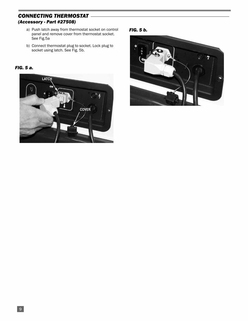
a) Push latch away from thermostat socket on control panel and remove cover from thermostat socket. See Fig.5a
b) Connect thermostat plug to socket. Lock plug to socket using latch. See Fig. 5b.
FIG. 5 a.
FIG. 5 b.
CONNECTING THERMOSTAT(Accessory - Part #27508)
149
LATCH
COVER

1410
1. Follow all ventilation and safety information.
2. Ensure electrical supply conforms to data platerequirments.
3. Fill tank with fuel.
4. Connect heater to an approved electrical supply.
5. The heater may be operated with or withoutthermostat. Without thermostat:,-- Push the top of the ON/OFF switch ( l ) to ON. The
motor will start, followed by ignition.-- The heater will operate until the switch is positioned
to OFF.With thermostat,-- Connect thermostat per instructions in this manual.-- Push the bottom of the ON/OFF switch (ll) to ON. -- The heater will start when thermostat is set above
surrounding air temperature.
6. When in normal operation, the Ignition control resetbutton with lamp emits a GREEN light.
7. When the unit is started for the first time or is startedafter the fuel tank has been totally emptied, the flowof fuel may be impaired by air in the circuit. Theignition control will shut the heater down. It may benecessary to restart the heater once or twice bydepressing the “Reset” button. To ease starting,remove the canister bottom from the pump’s fuel filterand fill with fuel. Reassemble the filter.
Start-Up Instructions
FIG. 6
RESET BUTTON WITHCONTROL LAMP
ON/OFF SWITCH THERMOSTAT SOCKETAND COVER
POWER CORD
POWER INDICATOR LIGHT

1. Turn thermostat dial to lowest temperature setting.This will shut the burner off. The motor will continueto run for 90 seconds. This allows the fan to cool thecombustion chamber. When the cooling cycle isfinished, the motor will stop.
2. Unplug extension cord from outlet.
3. To temporarily stop heater, set thermostat at atemperature lower than air around heater. Heater willcycle back on if air temperature around heatermatches thermostat setting.
Shut-Down Instructions
CAUTION
■ Do not unplug the heater while heater is in operation.
■ The heater must go through cooling cycle. The coolingcycle allows motor and fan operation after the burnerhas shut down. This cools the combustion chamber.
■ Damage to heater can occur if combustion chamber isnot cooled.
■ Do not restart heater until cooling cycle is complete.
Reset of the heater is required if the heater has failed in itsignition attempt.
RED light is observed at reset button:-- Position the ON/OFF switch to OFF.-- Push the reset button
-- Red light goes out.-- Push the ON/OFF switch to ON position (depending
if thermostat is used)-- Heater begins ignition trial.-- Light will turn GREEN once ignition is achieved..
Re-set Instructions
1411
1. Check all wiring associated terminals and electricalcomponents within the heater for corrosion, frayed orcut insulation, tight connections, etc. Repair orreplace as necessary.
2. Review all heater markings (i.e. wiring diagram,warnings, start-up, shut-down, etc.) at the time ofmaintenance for legibility. Make sure none are cut,torn, or otherwise damaged. Any damaged markingsmust be replaced immediately by contacting the L.B.White Co., Inc. Dataplates, start-up and shut-downinstructions and warnings are available at no cost. Anominal charge will be applied for wiring diagrams.
3. Inspect all fuel supply lines for cracks, abrasions, orruptures. Replace if needed.
4. The heater should be tagged and removed fromservice if it shows evidence of damage that is asafety or health hazard.
5. Refer to the following preventative maintenanceschedule:
Item Maintenance ScheduleFuel tank Flush every 50 hours of
operation or as needed
Fuel filter assembly Clean twice a heating seasonor replace as needed
Fuel filter lines Check and tighten loose connections before each use
Ignitors Clean and regap every 300 hours of operation orreplace if needed
Fan blades and Clean each season or air deflectors as needed
Air passages Check each season for dirtaround burner head and debris. Remove debris
with a clean, soft cloth.
Maintenance Instructions

WARNING
Do not use a pressure washer, water, or liquid cleaningsolution on any heater controls. Use of a pressurewasher, water, or liquid cleaning solution on the controlcomponents can cause severe personal injury orproperty damage due to water and/or liquids:
■ In electrical components, and wires causing electricalshock or equipment failure.
■ On fuel pump and hose connections causing corrosionwhich can result in fuel leaks and fire or explosion fromthe leak.
Clean all components of the heater with pressurized air, a dry brush, or a dry cloth.
Cleaning and Storage Instructions
WARNINGFire, Burn, and Explosion Hazard
■ This heater contains electrical and mechanical components in the fuel management, and safety systems.■ Such components may become inoperative or fail due to dust, dirt, wear and aging.■ Periodic cleaning and inspection as well as proper maintenance are essential to avoid serious injury or property
damage.
CLEANING
The heater should have dirt or dust removed periodically:
a. Before each use give the heater a general cleaningusing compressed air or a soft brush or dry rag onits case and internal components. At this time,dust off the motor case to prevent the motor fromover-heating.
b. At least once a year, give the heater a thoroughcleaning. At this time, remove the fan and motorassembly and brush or blow off the fan bladeassembly. Additionally, make sure the burner airventuri port is free of dust accumulation.
STORAGE
1. Drain all fuel from fuel filters, fuel lines, and pump.
2. Clean and flush fuel filter and canister.
3. Remove drain plug and drain fuel tank. Replace drainplug.
4. If any debris is noted in old fuel, add 1 or 2 quarts ofclean kerosene to tank, stir, and drain again. This willprevent debris from clogging filters during future use.Install fuel cap and drain plug.
5. Add 2 gallons of recommended fuel to fuel tank.Replace fuel cap.
6. Operate heater for 5 minutes (See Star t UpInstructions). Shut heater down, let it cool completely.
7. Remove drain plug and drain fuel tank. Replace drainplug.
8. Properly dispose of old and dirty fuel.
9. Store heater in a dry location. Make sure storageplace is free of dust and corrosive fumes.
Do not store kerosene over summer months for use duringnext heating season. Using old fuel could damage heater.
1412

1. Disconnect the electrical supply before servicingunless necessary for your service procedure.
2. Clean the heater’s nozzle with compressed air or asoft, dry rag. Do not use files, drills, broaches, etc. toclean the nozzle hole. Doing so will enlarge the hole,causing combustion or ignition problems. Replace thenozzle if it cannot be cleaned properly.
3. The high limit, thermostat, and air pressure switch canbe tested by disconnecting the leads at thecomponent, and jumpering the leads together:
-- Reconnect the electrical supply and open fuelsupply valves.
-- If the heater lights, the component is defectiveand must be replaced.
-- Do not leave the jumper on or operate the heater ifthe par t is defective. Replace the par timmediately.
-- An alternate method for checking the componentsis to perform a continuity check.
5. All serviceable components such as the burner, highlimit, switch,pump, motor, fan, and photocell areaccessed by removing the upper shell at the fan endof the heater. Electrical components,such as ignitionmodule,on/off switch, relay, and ignition transformer,are accessed by opening the control box on the heater.
6. Disconnect the electrical leads for the respectivecomponent.
7. For reassembly, reverse the respective serviceprocedure. Ensure fuel connections are tightenedsecurely.
8. After servicing, start the heater to ensure properoperation.
13
-- If cleaning out nozzle, remove the fuel line from the nozzle inlet as shown in Fig. 7. Blow out with air.
-- If removing nozzle from burner, proceed as follows.
1. Disconnect the fuel line, ignition cables, and photo cellfrom burner head. Loosen the three nuts at burner head.and remove head from heat chamber. See Fig.7.
2. Remove the nut as shown in Fig.8.
3. Remove nozzle with manifold and turbo disc fromhead.See Fig.9.
4. Loosen screw securing turbo disc to manifold. See Fig.9.
5. Remove the nozzle from the manifold.
BURNER NOZZLE
Service Instructions
WARNINGBurn Hazard
■ Heater surfaces are hot for a period of time after theheater has been shut down.
■ Allow the heater to cool before performing service,maintenance, or cleaning.
■ Failure to follow this warning will result in burnscausing injury.
WARNINGFire and Explosion Hazard
■ Do not disassemble or attempt to repair any heatercomponents.
■ All component parts must be replaced if defects arefound.
■ Failure to follow this warning will result in fire, causingproperty damage, injury, or death.
GENERAL
FIG. 7 FIG. 8
NUT
FUEL LINE
FIG. 9
IGNITION CABLES
PHOTOCELL
NUT
TURBO DISC
NOZZLE

Mounted on the heat chamber near the burner head,the high limit is a normally closed switch that opensif the burn chamber reaches abnormally hightemperatures, cutting power to the gas solenoid valve.
The switch may be tested by applying a soft flame forabout 20 seconds to the sensing side of the switchCheck for continuity before and after flame applicationto determine if the switch has opened. Allow theswitch to cool. Recheck continuity to ensure the switchhas closed.
FIG. 13
Removal
1. Disconnect fuel supply line from pump.
2. Using a 2.5 mm. allen key, loosen the three set screwswhere pump slides to motor shell. See Fig. 10.
3. Pull pump assembly from motor. Ensure pump coupling isin good condition.
4. Disconnect solenoid valve lead from pump.
FIG. 10
Checking Pressure
1. Remove pressure gauge plug from fuel pump port asshown in Fig.11, located in the upper right hand corner ofthe pump. Use a 4 mm allen wrench.
2. Install a pressure gauge that has 1/8-28 BSP (BritishStraight Pipe) threads to the fuel port marked “P”. SeeFig. 12. ( If 1/8 in. NPT is used, apply some pipe threadcompund to the threads)
3. Start heater (See Start-Up). Allow motor to reach fullspeed. Pump pressure must be that given on dataplateor Pg. 4 of Owner’s Manual.
4. To adjust pressure use 4mm allen wrench at adjustmentscrew, lower left of the pump, marked “-” and the “+” .Turn the allen head clockwise towards the “+” to increasethe pressure. Turn counter clockwise towards the “-” todecrease pressure. See Fig.11.
FIG. 11
Maintenance-- Before use, remove the filter using a 4 mm. allen key
and check for debris. See Fig.12.-- Rinse the filter with clean kerosene.
FIG. 12
14
SET SCREW
FUEL PUMP
COUPLING
PRESSURE GAUGE
ADJUSTPRESSURE
HIGH LIMIT SWITCH
HIGH LIMIT

FAN AND MOTOR
1. Remove the fan guard from the heater.
2. Using a 4 mm. allen key, loosen the set screw at thefan hub. See Fig. 15.
3. Slide the fan from the motor shaft.
4.. Disconnect the wiring for the motor and the capacitorfrom the junction box at the motor.
5. Remove the pump from the end of the motor oppositethe fan. (see Pump Service Instructions)
6. Remove all screws securing the motor to its support.See Fig.16.
NOTES: a. Ensure fan hub is spaced 1.25 inches fromshaft end. See Fig.15.
b. Fan set screw must be located directlyover the shaft flat before tightening.
FIG. 15
FIG.16
1.25
Set the air adjustment collar at the burner to compensate forchange in altitude. The heater is set from the factory tooperate at 1,000 ft. above sea level. Failure to set theburner’s air opening will result in smoke being emitted fromthe vent stack during operation.
FIG. 14
Loosen the wing screw at the burner head and slide theadjustmewnt collar accordingly to these opening sizes inthe table below. Note that these are approximate. Theopening should be increased or decreased asnecessary to prevent the heater from emitting smoke.
SETTING FOR HIGH ALTITUDE
SET SCREW
REMOVE ALL
15
Air Opening Setting Altitude
6 mm. 2,000’- 3,000’
7 mm. 4,000’- 5,000’
9 mm. 6,000’- 7,000WING SCREW
AIR OPENING

16
1. Remove the photocell by firmly grasping its body andpulling it from its holder. See Fig. 17.
2. Ensure tab on photocell body is firmly pushed withinslot of holder at reassembly to lock photcell in place
Cleaning-- Disconnect photcell from holder.-- Using a clean dry cloth, wipe lens of photocell.
Testing the photocell:-- Disconnect electrical leads of photocell.-- Connect ohm meter between leads.-- Note resistance of photocell. Ohm meter should read
anywhere from 50 to 60 k ohm.-- Shine a bright light (flash light) at the photocell lens.-- Resistance should drop to anywhere from 2 - 4 k
ohm. If no change in resistance, the photo cell is defective and should be replaced.
FIG. 17
PHOTOCELL
PHOTOCELL
IGNITERS
Cleaning and Checking Gapa. Loosen nuts at burner head.See Fig.18.b. Remove head from heat chamber.c. Clean the igniter tips using emery cloth.d. Ensure proper gap.See Fig.19
Replacement.
-- Follow steps a and b above.-- Remove the ignition cables and igniter mounting
screws.-- Ensure proper igniter gap after servicing.
FIG. 18
FIG. 19
5/32 in (.157 in.) 3/32 in. (.0938 ) 5/32 in. (.157)Y ZX
IGNITION CABLES
SCREWS
NUT
■ The air pressure switch is mounted to the inside of asmall access panel at the fan end of the heater. See Fig.20.
■ Ensure the switches flexible tubes and fittings are notblocked with dust/dir t or pinched. Tubes must besecurely connected to the pressure switch and fittings.
■ The tube fittings are located at the exterior below the fan(See Fig. 21) and in the lower barrel of the heater near awiring exit hole, see Fig. 22. Ensure this fitting ispositioned as shown.
■ The tube connected to the fitting below the fan guard isconnected to the barbed connection on lower section ofthe switch. The tube connected to the fitting at the lowerbarrel is connected to the barb on the upper section.
AIR PRESSURE SWITCH AND TUBING
FIG. 20
FIG. 21
FIG. 22
17
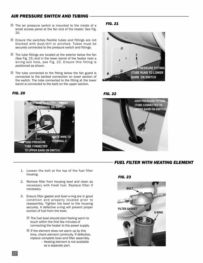
1. Loosen the bolt at the top of the fuel filterhousing.
2. Remove filter from housing bowl and clean asnecessary with fresh fuel. Replace filter ifnecessary.
3. Ensure filter gasket and bowl o-ring are in goodcondit ion and properly located prior toreassembly. Tighten the bowl to the housingsecurely. A defective o-ring will prevent propersuction of fuel from the bowl.
■ The fuel bowl should start feeling warm to touch within the first few minutes of connecting the heater to the power supply.
■ If the element does not warm up by this time, check element continuity. If defective, replace complete bowl and filter assembly.
-- Heating element is not available as a separate part.
FUEL FILTER WITH HEATING ELEMENT
O-RING
BOLT
FIG. 23
FILTER GASKET
HIGH PRESSURETUBE CONNECTEDTO UPPER BARB ON SWITCH.
RED WIRE TO NORMALLY OPEN(NO +) TERMINAL ON SWITCH
WHITE WIRE TOTERMINAL C
LOW PRESSURE FITTING(TUBE RUNS TO LOWER BARB ON SWITCH
HIGH PRESSURE FITTING(TUBE CONNECTED TOUPPER BARB ON SWITCH)

READ THIS ENTIRE SECTION BEFORE BEGINNING TOTROUBLESHOOT PROBLEMS.
This guide is intended for use by a QUALIFIED HEATERSERVICE PERSON. DO NOT ATTEMPT TO SERVICE THESEHEATERS UNLESS YOU HAVE BEEN PROPERLY TRAINED.
TEST EQUIPMENT REQUIRED
The following pieces of test equipment will be required totroubleshoot this system with minimal time and effort.
• Digital Multimeter - for measuring AC voltage and resistance.
• High Pressure Gauge - for checking pressures at the fuel pumpagainst dataplate rating.
■ Visually inspect equipment for apparent damage.
■ Check all wiring for loose connections and worninsulation.
Components should be replaced only after each step hasbeen completed and replacement is suggested in the flowchart. Refer to the Servicing sections as necessary to obtaininformation on disassembly and replacement procedures ofthe component once the problem is identified by the flowchart.
Refer to the system operation sequence in this section to gainan understanding as to how the heater operates during a callfor heat. Understanding the sequence of operation isimportant as it relates to problem solving.
If the heater is operating and ignition failure occurs, theheater will attempt one retrial for ignition. If the retry fails, theheater locksout, with the reset button emitting a red light
If RED light is observed at reset button:-- Heater has failed ignition attemptTO RESET-- Position the ON/OFF switch to OFF.-- Push and release the reset button.
-- Red light goes out.-- Push the ON/OFF switch to ON position (depending
if thermostat is used)-- Heater begins ignition cycle-- Light will turn GREEN.-- If ignition failure occurs and light turns RED, observe
ignition sequence to determine cause of failure.
Problems PageMotor does not run, heater does not light. . . . . . . . . . . . . .19
Motor runs,heater ignites, emits smoke. . . . . . . . . . . . . . . .19
Motor runs, igniter does not spark . . . . . . . . . . . . . . . . . .20
Motor runs, ignitor sparks, heater does not light.or lights but goes out . . . . . . . . . . . . . . . . . . . . . . . . . . . . .20
Motor shuts off immediately after burner shuts down . .20
OPERATION SEQUENCE:-- Power cord is connected to line voltage.-- Line voltage is sent to fuse.-- Fuse sends voltage to:
- Indicator lamp- Heated fuel filter- Relay- ON/OFF switch
-- ON/OFF switch set to on.-- Power sent to thermostat (if used)-- Thermostat closes and voltage is returned from thermostat
to ignition control. (GREEN light comes on from reset)-- Ignition control sends voltage to motor relay.
-- Relay closes- Sends power to fan motor.
- Fan motor starts- Fan motor turns pump, creating fuel pressure
-- Ignition control module sends voltage to ignition transformer and to solenoid valve
-- Ignition transformer sends high voltage to igniters- Ignitors spark
-- Solenoid valve opens-- Ignition occurs
- Ignitor continues to spark until photocell proves flame.
- Ignitor stops sparking.-- Thermostat opens once heat demand is satisfied-- Ignition control keeps the fan motor running for 90 seconds
to allow a cool down cycle for the heat chamber.- Ignition control shuts off fan motor
-- Proces begins again on a call for heat
IGNITION FAILURE SEQUENCE:-- Trial for ignition takes approximately 20 seconds.-- If photocell does not prove burner flame exists:
-- Fuel solenoid valves close.-- Ignition spark shuts off.-- Fan motor stops.-- RED light comes on from reset.
-- To retry for ignition, the system must be reset:-- Refer to Reset Instructions
Troubleshooting Information
WARNING■ This heater can start at any time.
■ Troubleshooting this system may require operating theheater with line voltage present. Use caution whenworking on the heater.
■ Failure to follow this warning may result in propertydamage, personal injury or death.
18

Pro
blem
Mot
or d
oes
not
run
on c
all
for h
eat
Is h
eate
rpl
ugge
d in
?
Is
sele
ctor
switc
h se
t to
ON
?
Plug
hea
ter i
n.M
ove
the
sele
ctor
sw
itch
to th
e O
Npo
sitio
n.
Yes
No
Yes
Yes
Is
prop
er v
olta
gesu
pplie
d to
pow
erco
rd?
Def
ectiv
em
otor
or
capa
cito
r
Set t
he th
erm
osta
t to
ate
mep
ratu
re s
ettin
gab
ove
room
tem
pera
ture
No
No
Yes
Is
ther
mos
tat s
et to
call
for h
eat?
No
Yes
Doe
s fu
se d
eliv
er
prop
er v
olta
ge?
Rep
lace
the
switc
h.
No
Is O
N/O
FF s
witc
hse
ndin
g ou
t pow
erw
hen
post
ione
d to
ON
? No
Chec
k fu
se fo
r con
tinui
ty. I
fno
ne, r
epla
ce fu
se.
Yes Ch
eck
ther
mos
tat f
or c
ontin
uity
.R
epla
ce if
def
ectiv
e.
Doe
s th
erm
osta
tse
nd o
ut v
olta
gere
ceiv
ed fr
omO
N/O
FF s
witc
h?
No
Yes
Chec
k fo
r pro
per w
iring
inte
grity
. If g
ood,
repl
ace
igni
tion
cont
rol.
Is re
lay
rece
ivin
gvo
ltage
from
igni
tion
cont
rol?
No
Yes
Def
ectiv
e re
lay.
Is re
lay
send
ing
pow
er to
fan
mot
or?
No
Yes
Det
erm
ine
elec
tric
al re
quire
men
ts o
fhe
ater
. Ens
ure
it m
atch
es p
ower
supp
ly.
Chec
k w
iring
of p
ower
sup
ply
to h
eate
r.
Mot
or ru
ns,
heat
er ig
nite
s,bu
t em
its s
mok
e
Yes
Are
air i
nlet
and
outle
t fre
e of
bloc
kage
s?
Rem
ove
bloc
kage
s
No
Verif
y co
llar
sett
ing.
and
air
open
ing.
No
Is a
ir ad
just
men
t col
lar
on b
urne
r set
to p
rope
rse
ttin
g fo
r alti
tude
?
Yes
Chec
k th
e fu
el li
nes
for
tight
ness
. If t
ight
, che
ckfo
r lea
ks. R
epla
ce if
leak
sar
e fo
undN
o
Hav
e fu
el li
nes
been
che
cked
for
leak
s?
Dra
in a
nd re
fill w
ith c
lean
fuel
. Ch
eck
filte
r and
filte
rbo
wl.
Clea
n w
ith fr
esh
kero
sene
.
No
Are
fuel
and
filte
rcl
ean
Yes
Chec
k o-
ring.
If d
efec
tive,
repl
ace
it.
No
Is fu
el fi
lter
o-rin
g in
good
cond
ition
?
Yes
Wat
er c
onde
nsat
ion
in fu
elta
nk. D
rain
and
fill
with
fres
h fu
el.
Has
noz
zle
been
chec
ked
for
bloc
kage
?
Rem
ove
nozz
le a
nd c
lean
it w
ith p
ress
uriz
ed a
ir.
No
Yes
Yes
19
Is p
ump
pres
sure
set
to re
quire
men
ts?
Chec
k fo
r cor
rect
pres
sure
.
No
Yes
Doe
s re
lay
rece
ive
pow
erw
hen
heat
eris
plu
gged
in?
Def
ectiv
e w
iring
or
elec
tric
al c
onne
ctio
n.R
epai
r as
need
ed.
No

Mot
or ru
ns,
Igni
ter d
oes
not s
park
.
Rep
lace
igni
tor.
No
Chec
k fo
r pro
per v
olta
gefr
om c
ontr
ol m
odul
e to
igni
tion
tran
sfor
mer
. Che
ckal
l wiri
ng c
onne
ctio
ns. I
fco
ntro
l boa
rd is
not
send
ing
volta
ge to
igni
tion
tran
sfor
mer
, rep
lace
igni
tion
cont
rol m
odul
e.
Has
ig
nito
r ass
embl
ybe
en c
lean
ed?
No
Yes
Is ig
nitio
ntr
ansf
orm
erre
ceiv
ing
prop
ervo
ltage
from
con
trol
mod
ule?
Yes
Yes
Is h
eate
rre
ciev
ing
prop
ervo
ltage
?
Det
erm
ine
elec
tric
alre
quire
men
ts o
f hea
ter.
Ensu
re it
mat
ches
pow
ersu
pply
. Ch
eck
wiri
ng o
f pow
ersu
pply
to h
eate
r.
No
Is
igni
tion
tran
sfor
mer
send
ing
out h
igh
volta
ge?
Chec
k bo
th ig
nitio
n ltr
ansf
orm
er le
ads
for c
ontin
uity
. If
lead
s ar
ego
od,d
eter
min
e if
igni
tion
tran
sfor
mer
is s
endi
ng h
igh
volta
ge.:
-- D
isco
nnec
t sol
enoi
d va
lve
wiri
ng.
-- R
emov
e ig
nitio
n le
ads
from
igni
tor
--Hol
d a
scre
wdr
iver
tip
abo
ut 1
/8 in
.fr
om e
nds
of b
oth
lead
s.--
Turn
hea
ter o
n.--
Spar
k sh
ould
be
seen
from
bot
hle
ads.
If n
one,
repl
ace
igni
tion
tran
sfor
mer
.
No
Ensu
re le
ads
are
conn
ecte
d at
igni
tion
tran
sfor
mer
and
ignf
itor.
No
Are
igni
tion
tran
sfor
mer
lead
sse
cure
ly c
onne
cted
?
Is
igni
tor i
nsul
ator
crac
ked?
Yes
No
Clea
n th
e ig
nito
rel
ectr
odes
. Use
em
ery
clot
h.
Yes
Yes
Pro
blem
Chec
k th
e ig
nito
rga
p. R
efer
toig
nito
r gap
ping
inst
ruct
ions
in th
ism
anua
l.
Mot
or ru
ns,
igni
ter
spar
ks,
heat
er d
oes
not
light
, or l
ight
san
d go
es o
ut
Ensu
re fi
ttin
gs a
repo
sitio
ned
acco
rdin
g to
illus
trat
ions
in m
anua
l.
No
Are
air t
ube
fittin
gs p
rope
rlypo
sitio
ned?
Chec
k tu
bes
and
fittin
gs. I
f nec
essa
ryre
mov
e an
d bl
ow o
utw
ith a
ir.No
Are
air p
ress
ure
tube
san
d fit
tings
cle
an?
Verif
y tu
bes
are
secu
re a
nd p
rope
rlyco
nnec
ted.
No
Are
air p
ress
ure
switc
h tu
bes
secu
rely
conn
ecte
d to
pro
per
port
s at
air
pres
sure
switc
h?
Yes
If fu
el ig
nite
s bu
tbu
rner
goe
s ou
t,ch
eck
phot
ocel
l.R
epla
ce if
defe
ctiv
e.
20
Yes
Yes
Chec
k fo
r con
tiuity
or
jum
per t
he s
witc
h. if
switc
h is
ope
n or
hea
ter
igni
tes
afte
r byp
assi
ngth
e sw
itch,
repl
ace
switc
h
No
Is h
igh
limit
heat
switc
h cl
osed
?M
otor
shu
ts o
ff im
med
iate
ly a
fter c
all
for h
eat i
s sa
tisfie
d
Ensu
re g
ood
elec
tric
alco
nnec
tions
. If g
ood,
repl
ace
valv
e.
No
Doe
s so
leno
idva
lve
open
?Ye
sYe
s
Chec
k fo
r pro
per p
ress
ure.
Ensu
re m
otor
is o
pera
ting
prop
erly
. Che
ck c
ondi
tion
ofco
uplin
g be
twee
n pu
mp
and
mot
or.
If m
otor
and
cou
plin
gar
e go
od, a
nd p
ump
pres
sure
cann
ot b
e se
t, re
plac
e pu
mp.
No
Has
pum
ppr
essu
re b
een
chec
ked?
Rec
onne
ct h
eate
r to
its p
ower
sup
ply
and
rese
t the
hea
ter
No
Is h
eate
rco
nnec
ted
to it
spo
wer
sup
ply?
Yes
Chec
k tu
bes
and
fittin
gs. I
f nec
essa
ryre
mov
e an
d bl
ow o
utw
ith a
ir.
Def
ectiv
eig
nitio
n co
ntro
l.R
epla
ce c
ontr
ol.
Yes St
art
the
heat
er. C
heck
cont
inui
ty a
cros
s sw
itch
term
inal
s. If
con
tact
s ar
e op
en,
jum
per t
he s
witc
h. I
f hea
ter
igni
tes,
the
switc
h is
def
ectiv
e.
No
Are
air p
ress
ure
switc
h co
ntac
tscl
osed
?
Yes
Secu
rely
att
ach
the
case
at f
an e
nd to
heat
er.
No
Is u
pper
cas
e at
fan
end
secu
rely
fast
ened
to h
eate
r?
Yes

Electrical Connection
21
AUTO RESETLIMIT SWITCH
NEUTRAL

22
Heater Component Function
Air Pressure Switch
Safety device used to insure that the proper air flow is beingachieved as the gas solenoid is opened.
Burner
Mounted to the rear of the combustion chamber. The burnermeters and mixes the amount of air entering the chamber toobtain proper combustion charactersitcs.
Fan Blade Assembly
Component used in conjunction with the motor to push thecool air over the heat exchanger for transfer of heat beforeblowing it into the occupied area.
Filter
The purpose of the filter is to trap very small particles whichmay be present in in the fuel system. The high degree offiltering is necessary to prevent foreign materials fromentering the burner nozzle.
Fuel Heating Element
Ensures the fuel being supplied to the pump remains inliquid form even when the heater is used on cold days.
Heat Exchanger
Sealed combustion chamber over which cool air passes forheat transfer. Also provides an area where burner flamemixes with combustion air, thereby providing heat.
High Limit Switch
Safety device wired into the control system, used to breakthe electrical circuit to the solenoid valve in the event of anoverheat situation.
Igniter
Ignition device used on automatic direct spark ignitioncontrol systems. Ignites fuel by spark.
Ignition Control
Cicuit board which sends voltages to various controls in anautomatic ignition system, and monitors safe operation ofthe heater. The device also incorporates a reset which mustbe pushed to restart the heater if ignition fails
Ignition Transformer
Receives 120 volts from the ignition module and thenboosts it to a very high voltage at the ignitor causing the fuelsprayed from the nozzle to ignite.
Motor
Electric device used to force preheated air through theheater and to circulate heat within a certain area. Convertselectrical energy into mechanical energy. Drives the pumpand rotates the fan.
Nozzle
Sprays the fuel under pressure from the pump. .
On/Off Switch
Simple electrical device used to supply power to the ignitioncontrol for heater operation.
Photocell
A light senstive resistor. Used to sense the presence of lightin the combsution chamber, allowing the heater to continueits operation.
Pump
Connected to the motor shaft by a coupling, the pump pullsfuel from the tank and forces it to the nozzle under pressurefor ignition when the fan motor is in operation.
Relay
Electrical component wired between ignition control andmotor. Used to feed voltage to motor upon receipt of voltagefrom ignition control.
Solenoid Valve
Electro-megnetic device mounted on the pump body. Thesolenoid acts as an on/off valve for fuel flow to the burnernozzle. On this heater, there are two solenoid valves,creating two stages of heat.
Thermostat
Electrical device used as an automatic “on/off” switch whichwill respond to changes in temperature in a certain area.Can be wired so contacts in the thermostat open or close ontemperature increase or decrease.

Parts Identification
PARTS SCHEMATIC
23
55
54
58
5956
60
57 61
63 62
31
B
4645
43
4442
41
40
53
52
5149
50
47
72
A76
64
65
66
14
68
67
61
28 27
2625
2930
24
73
74
33
21
20
16
18
2317
18 17
12
11
75
78
77
7874
10
39
9
8A
32
3122
38
B
7
3736
34
35
3
4
1 25
6
1314 78
6970
71
141516
19
24

PARTS LIST
* Bold Item Numbers Indicate Immediate Parts Availability.
Item Description1 Outlet cone 5723922 Chimney 150mm 5723933 Combustion chamber support 5726004 Combustion chamber 5725995 Exhaust end upper case 5723966 Fan end upper case 5723977 Lower case 5725988 Motor w/capicitor 5723999 Capacitor 80 uF 572601
10 Motor flange 57240111 Axial fan 57240212 Fan guard 57044913 Fuel line with fittings 57260214 Hose fitting 57240315 Filter support 57264516 Fuel line 57259717 Handle and leg 57239118 Plug 57272819 Fuel line 1/4 x 24 in. 57238820 Siphon tube and fitting 57238721 Fitting,siphon tube 57264422 Cord bracket 57240423 Fuel tank with cap 57238424 Fuel cap (standard) 572386
(with fuel gauge) 57264725 Axle with supports 57238526 Support, axle 57264227 Wheel wtih spring washer 57238328 Spring washer 57264329 Drain plug with o ring 57238230 O ring for drain plug 57264631 Electrical componets compartment assembly 57260632 Control box cover 57238133 Bushing 57263834 High limit switch 57088735 Washers for limit switch 57263936 Burner head 57260437 Terminal,burner ground 57261138 Altitude adjustment collar 57260839 Air diverter 57260740 Electrical drawer 57260541 Fuse holder 57237242 Fuse 57008643 Terminal block 57261044 Relay 57013245 Terminal strip 57260946 Ignition transformer 57261247 Ignition control 57261348 Electrical components plate 57261449 Switch ON/OFF 57236650 Thermostat plug 572615
24

PARTS LIST (cont.)
* Bold Item Numbers Indicate Immediate Parts Availability.51 Thermostat cap 57236552 Power cord 57236453 Indicator lamp 57236354 Nozzle 57261655 Burner disc 57261756 Ignitor 57261857 Nut, 57261958 Nozzle manifold 57262059 Burner flange 57262160 Ignition cables,high voltage 57262261 Fuel line 57235562 Photocell 57262363 Holder, photocell 57262464 Pump 57262565 Solenoid spool 57262666 Solenoid valve 57262767 Hose Fitting 57235568 Coupling 57235669 Heated fuel filter assembly 57238970 O ring / gasket kit for fuel filter 57264071 Fuel Filter with o ring and gasket 57235472 Reset switch cover 57262873 Air pressure swich 57263074 Tubing air pressure switch 57263175 Straight connection 57263276 Solenoid valve cable 57263377 Connection, 1/8 in. 57263478 Connection 572635
25

Contact your local L.B. White dealer for replacement partsand service or call the L.B. White Co., Inc. at (800) 345-7200 for assistance. Be sure that you have your heatermodel number and configuration number when calling.
L.B. White Co., Inc. warrants that the component parts of itsheater are free from defects in material and workmanship,when properly installed, operated, and maintained inaccordance with the Owner’s Manual safety guides andlabels contained with each unit. If, within 12 months fromthe date of purchase by the end user, any component isfound to be defective, L.B. White Co., Inc. will at its option,repair or replace the defective part or heater, with a newpar t or heater, F.O.B., Onalaska, Wisconsin.
A warranty card on file at L.B. White will automaticallyqualify the heater and its component parts for warrantyconsideration. If a warranty card is not on file, a copy of thebil l of sale wil l be required to establish warrantyqualification. If neither is available, the warranty period willbe 12 months from date of shipment from L B. White.
Warranty Policy
Replacement Parts and Service
EQUIPMENT
PARTS
L.B. White Co., Inc. warrants that replacement partspurchased from the company and used on the appropriateL. B. White heater are free from defects both in material andworkmanship for 12 months from the date of purchase bythe end user. Warranty is automatic if a component is founddefective within 12 months of the date code marked on thepart. If the defect occurs more than 12 months later thanthe date code but within 12 months from the date ofpurchase by the end user, a copy of a bill of sale will berequired to establish warranty qualification.
The warranty set forth above is the exclusive warrantyprovided by L.B. White, and all other warranties, includingany implied warranties or merchantability or fitness for aparticular purpose, are expressly disclaimed. In the eventany implied warranty is not hereby effectively disclaimeddue to operation of law, such implied warranty is limited in
duration to the duration of the applicable warranty statedabove. The remedies set forth above are the sole andexclusive remedies available hereunder. L.B. White will notbe liable for any incidental or consequential damagesdirectly or indirectly related to the sale, handling or use ofthe heater, and in any event L.B. White's liability inconnection with the heater, including for claims based onnegligence or strict liability, is limited to the purchase price.
Some states do not allow limitations on how long an impliedwarranty lasts, so the above limitation may not apply to you.Some states do not allow the exclusion or limitation ofincidental or consequential damages, so the abovelimitation or exclusion may not apply to you. This warrantygives you specific legal rights, and you may also have otherrights which vary from state to state.
26