Embed Size (px)
Citation preview
Zadar - Capri
OWNER'S MANUAL
AntibesMaiorca
This manual must be considered as an integral part of your outboard motor and has to be kept with it, also if the motor is resold. Selva joint-stock CO. reserve the right to change its product at any moment, except for the essential specifications, which will be kept as they are. Any reference to products or details of a third party has only an informative purpose and it doesn't represent an obligation. Selva joint-stock CO. doesn't take on any responsibility concerning the performance or the employment of these products.
We are glad that you have chosen a SELVA MARINE product, which means quality, technology and careful research. Your choice
will give you many advantages, which you will soon learn to appreciate. Our dealers, our after-sales service and the guarantee,
which you have signed, together with the observance of the information contained in this owner's manual are the essential
conditions to give your recent purchase a long life.
Your holiday, your favourite sport, your job, which has from today the name SELVA MARINE, will be a further moment of
satisfaction.
This manual belongs to Selva joint-stock CO. All rights reserved. Any partial or total reprinting without the permission is
prohibited.
INTRODUCTION Before operating this outboard motor, read this Owner's Manual carefully and completely, pay attention especially to the safety measures and rules. Your safety and other people's safety do not depend only on your ability at using the motor, but they depend also on your knowledge and on the efficiency of the motor as well as on the respect of the laws and regulations relating to the use of outboard motors. We suggest you improve your knowledge of the motor so that you can sail with mastery and confidence. If any kind of repair on the motor should not have been clearly described in this manual or if you want to order spare parts or accessories, or if you have any question about the operation or maintenance of your outboard motor, please consult an authorised SELVA MARINE service station or SELVA MARINE dealer
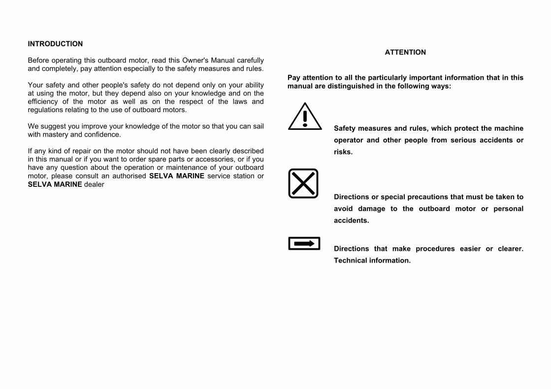
ATTENTION
Pay attention to all the particularly important information that in this manual are distinguished in the following ways:
Safety measures and rules, which protect the machine operator and other people from serious accidents or risks.
Directions or special precautions that must be taken to avoid damage to the outboard motor or personal accidents.
Directions that make procedures easier or clearer. Technical information.
3
OUTBOARD MOTOR IDENTIFICATION DATA This data is stamped on the label attached on the clamp bracket, as shown on the picture 1. When you receive your new SELVA outboard motor write down the serial number, it will be useful to you in case you will have to order spare parts or for reference if your outboard motor should be stolen.
Make sure that the data on the label is the same as the data written in your registration book. Picture No.1
Do not install an outboard motor with more horsepower than shown in the certification of your boat.
SERIAL NUMBER RECORD
Write down the identification number and the model of your outboard
motor in the spaces below.
MODEL
SERIAL NUMBER
4
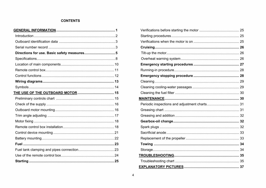
CONTENTS GENERAL INFORMATION.............................................................1 Introduction ....................................................................................2 Outboard identification data ..........................................................3 Serial number record .....................................................................3 Directions for use. Basic safety measures................................5 Specifications.................................................................................8 Location of main components.......................................................10 Remote control box.......................................................................11 Control functions...........................................................................12 Wiring diagrams..........................................................................13 Symbols ........................................................................................14
THE USE OF THE OUTBOARD MOTOR......................................15 Preliminary controls chart ............................................................15 Check of the supply ......................................................................16 Outboard motor mounting.............................................................16 Trim angle adjusting .....................................................................17 Motor fixing ...................................................................................18 Remote control box installation.....................................................18 Control device mounting ...............................................................21 Battery mounting...........................................................................22 Fuel ..............................................................................................23 Fuel tank clamping and pipes connection.....................................23 Use of the remote control box.......................................................24 Starting ........................................................................................25
Verifications before starting the motor ......................................... 25 Starting procedures...................................................................... 25 Verifications when the motor is on ............................................... 25 Cruising....................................................................................... 26 Tilt-up the motor........................................................................... 26 Overheat warning system ............................................................ 26 Emergency starting procedures ............................................... 27 Running-in procedure................................................................... 28 Emergency stopping procedure ............................................... 28 Cleaning ....................................................................................... 29 Cleaning cooling-water passages ................................................ 29 Cleaning the fuel filter .................................................................. 30
MAINTENANCE............................................................................. 30 Periodic inspections and adjustment charts................................. 31 Greasing chart ............................................................................. 31 Greasing and addition .................................................................. 32 Gearbox-oil change.................................................................... 32 Spark plugs .................................................................................. 32 Sacrificial anode........................................................................... 33 Replacement of the propeller ....................................................... 33 Towing ........................................................................................ 34 Storage......................................................................................... 34
TROUBLESHOOTING................................................................... 35 Troubleshooting chart .................................................................. 35
EXPLANATORY PICTURES......................................................... 37
5
DIRECTIONS FOR USE
BASIC SAFETY MEASURES To use the outboard motor you must have all the requisites provided by law (physical suitability, insurance, government duties, registration, and so on). We suggest you become familiar with your boat equipped with SELVA motor in places, which are not too crowded. Taking some medicines, alcoholic drinks or drugs increase considerably the risk of accidents. Make sure that you are in a physical condition suitable for driving. Pay attention to tiredness. The engine operator should not let his mind wander, or be distracted or influenced by other people, things or actions,(do not smoke, eat, read, and so on.) while steering the boat.
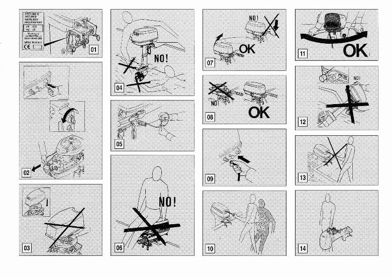
Use fuels and oils suitable for the engine, which are listed in the "greasing chart ". Check every so often the oil level and the fuel level. Stop the motor before every kind of maintenance or cleaning procedures, and in case of complicated maintenance take the spark-plug cap out. Picture No. 2. Before opening the top cowling, wait till the engine has cooled. Do not open the top cowling, when the engine is running. Picture No. 3.
6
PAY ATTENTION TO THE PROPELLER The propeller is certainly the least protected part of your motor. It is therefore forbidden to get near the propeller when this is rotating. You must leave bathers, skiers and other boats users enough space to move, in order to avoid any contact with the propeller. Picture No. 4. The engine operator must attach the engine stop switch lanyard to his wrist when the motor is on. Picture No. 5. Never sit on the motor. Picture No. 6. Never change the inclination angle of your motor using the steering rod, but use the proper handle. Picture No. 7. The motor must always have its top cowling on, when it is operating Picture-No. 8. When you connect the fuel joint, check the proper connection Picture No. 9. When starting there must be nobody within the engine operator's action radius.( model with manual start ). Picture No. 10.
There must be nobody within the motor steering radius. Picture No. 11. The free lock lever must always be engaged while the motor is in motion. Never tilt-up the motor out of the water, while it is in motion. Picture No. 12. Never pull the recoil starter handle, while the motor is running.(model with manual start ). Picture No. 13. To transport the motor use only the proper handle. Before transporting the motor you have to tilt-up the steering rod properly. The fuel tank is also provided with a handle to use for the transport. Picture No. 14. When starting or operating the engine, do not touch electrical parts and particularly the ignition-coil, the high voltage wire, the spark-plug cap and the spark-plug itself. When opening the safety valve of the fuel tank, highly flammable vapours come out. Do not smoke, inhale or use open flames close to it.
7
If the motor has had an accident, you should have it fully checked, before you use it again. If necessary let the SELVA MARINE authorised skilled staff have a look at it. Do not use the motor, if the damage could have compromised the sailing safety. Any alteration attempted on your motor or the removal of any of its basic elements, can compromise its safety, it is against the law, and it means the immediate loss of your guarantee. Observe the laws in force. Pay great attention to the weather conditions. Listen to the weather forecast and take the warnings to the sailors into consideration. Keep your boat and equipment on board in a perfect state of efficiency. Keep enough spare parts on board. Inform somebody of your route, before sailing.
Prevent fires and explosions. Before operating an outboard motor, you must know the laws and regulations relating to navigation. Avoid sudden and dangerous manoeuvres SELVA motors are only meant as propulsion for pleasure craft. SELVA joint-stock CO. declines all responsibility for any damage to items or harm done to any person, which is due to an improper use of the motor.
8
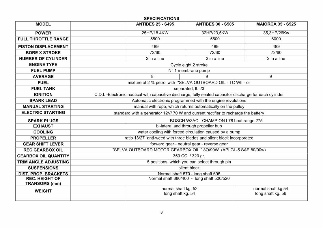
SPECIFICATIONS MODEL ANTIBES 25 - S495 ANTIBES 30 - S505 MAIORCA 35 - S525
POWER 25HP/18.4KW 32HP/23,5KW 35,3HP/26Kw FULL THROTTLE RANGE 5500 5500 6000
PISTON DISPLACEMENT 489 489 489 BORE X STROKE 72/60 72/60 72/60
NUMBER OF CYLINDER 2 in a line 2 in a line 2 in a line ENGINE TYPE Cycle eight 2 stroke FUEL PUMP N° 1 membrane pump AVERAGE 8 9 9
FUEL mixture of 2 % petrol with "SELVA OUTBOARD OIL - TC WII - oil FUEL TANK separated, lt. 23
IGNITION C.D.I. -Electronic nautical with capacitive discharge, fully sealed capacitor discharge for each cylinder SPARK LEAD Automatic electronic programmed with the engine revolutions
MANUAL STARTING manual with rope, which returns automatically on the pulley ELECTRIC STARTING standard with a generator 12V/ 70 W and current rectifier to recharge the battery
SPARK PLUGS BOSCH W3AC - CHAMPION L78 heat range 275 EXHAUST bi-lateral and through propeller hub COOLING water cooling with forced circulation caused by a pump
PROPELLER ratio 13/27 anti-weed with three blades and silent block incorporated GEAR SHIFT LEVER forward gear - neutral gear - reverse gear REC.GEARBOX OIL "SELVA OUTBOARD MOTOR GEARBOX OIL " 8O/90W (API GL-5 SAE 80/90w)
GEARBOX OIL QUANTITY 350 CC. / 320 gr. TRIM ANGLE ADJUSTING 5 positions, which you can select through pin
SUSPENSIONS silent block DIST. PROP. BRACKETS Normal shaft 570 - long shaft 695
REC. HEIGHT OF TRANSOMS (mm)
Normal shaft 380/400 - long shaft 500/520
WEIGHT normal shaft kg. 52 long shaft kg. 54
normal shaft kg.54 long shaft kg. 56

9
MODEL
ANTIBES 15XS S505XS
ANTIBES 20XS S495XS
ANTIBES 25XS S505XS
MAIORCA 25XS S495XS
MAIORCA 30XS S525XS
POWER 15HP/11KW 20HP/14.7KW 25HP/18.4KW 25HP/18.4KW 30HP/22KW FULL THROTTLE RANGE 5000 5000 5500 6000 6000 PISTON DISPLACEMENT 489
BORE X STROKE 72/60NUMBER OF CYLINDER 2 in a line
ENGINE TYPE Cycle eight 2 strokeFUEL PUMP N° 1 membrane AVERAGE 7 8 9 9 9,5
FUEL mixture of 2% petrol with "SELVA OUTBOARD OIL - TC WII - oil FUEL TANK separated, lt. 23
IGNITION C.D.I. -Electronic nautical with capacitive discharge, fully sealed capacitor discharge for each cylinder SPARK LEAD Automatic electronic programmed with the engine revolutions
MANUAL STARTING manual with rope, which returns automatically on the pulley ELECTRIC STARTING standard with a generator 12V/ 70 W and current rectifier to recharge the battery
SPARK PLUGS BOSCH W6B-CHAMPION L87Y DEGREE TERM.200 EXHAUST bi-lateral and through propeller hub COOLING water cooling with forced circulation caused by a pump
PROPELLER ratio 13/27 anti-weed with three blades and silent block incorporated GEAR SHIFT LEVER forward gear - neutral gear - reverse gear REC.GEARBOX OIL "SELVA OUTBOARD MOTOR GEARBOX OIL " 8O/90W (API GL-5 SAE 80/90w)
GEARBOX OIL QUANTITY 350 CC. / 320 gr. TRIM ANGLE ADJUSTING 5 positions, which you can select through pin
SUSPENSIONS silent block DIST. PROP. BRACKETS Normal shaft 570 - long shaft 695
REC. HEIGHT OF Normal shaft 380/400 - long shaft 500/520WEIGHT normal shaft kg. 52 long shaft kg. 54
normal shaft kg.54 long shaft kg. 56
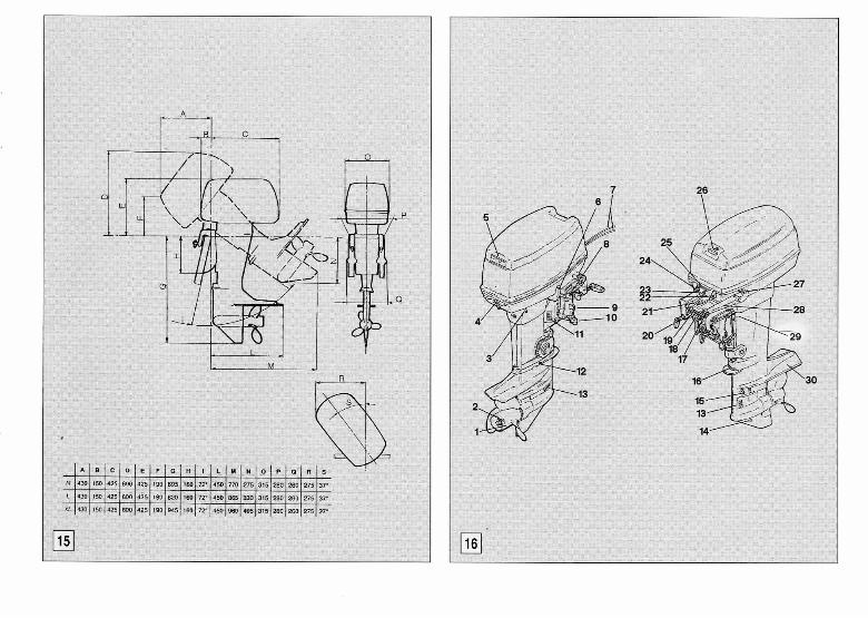
Selva joint stock CO reserve the right to change weight, construction, materials and characteristics without warning and without therefore have to change the motors, which were built previously. See picture N. 15 for the dimensions
10
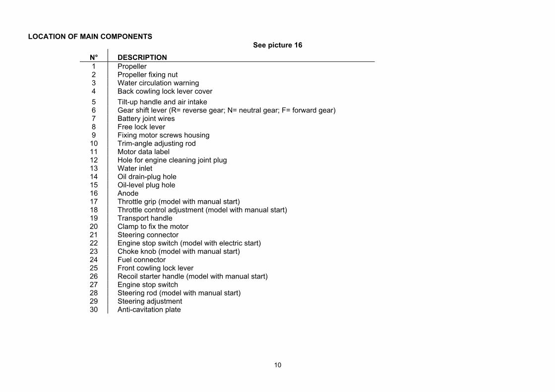
LOCATION OF MAIN COMPONENTS
See picture 16 N° DESCRIPTION 1 Propeller 2 Propeller fixing nut 3 Water circulation warning 4 Back cowling lock lever cover 5 Tilt-up handle and air intake 6 Gear shift lever (R= reverse gear; N= neutral gear; F= forward gear) 7 Battery joint wires 8 Free lock lever 9 Fixing motor screws housing
10 Trim-angle adjusting rod 11 Motor data label 12 Hole for engine cleaning joint plug 13 Water inlet 14 Oil drain-plug hole 15 Oil-level plug hole 16 Anode 17 Throttle grip (model with manual start) 18 Throttle control adjustment (model with manual start) 19 Transport handle 20 Clamp to fix the motor 21 Steering connector 22 Engine stop switch (model with electric start) 23 Choke knob (model with manual start) 24 Fuel connector 25 Front cowling lock lever 26 Recoil starter handle (model with manual start) 27 Engine stop switch 28 Steering rod (model with manual start) 29 Steering adjustment 30 Anti-cavitation plate
11
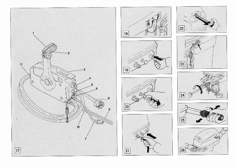
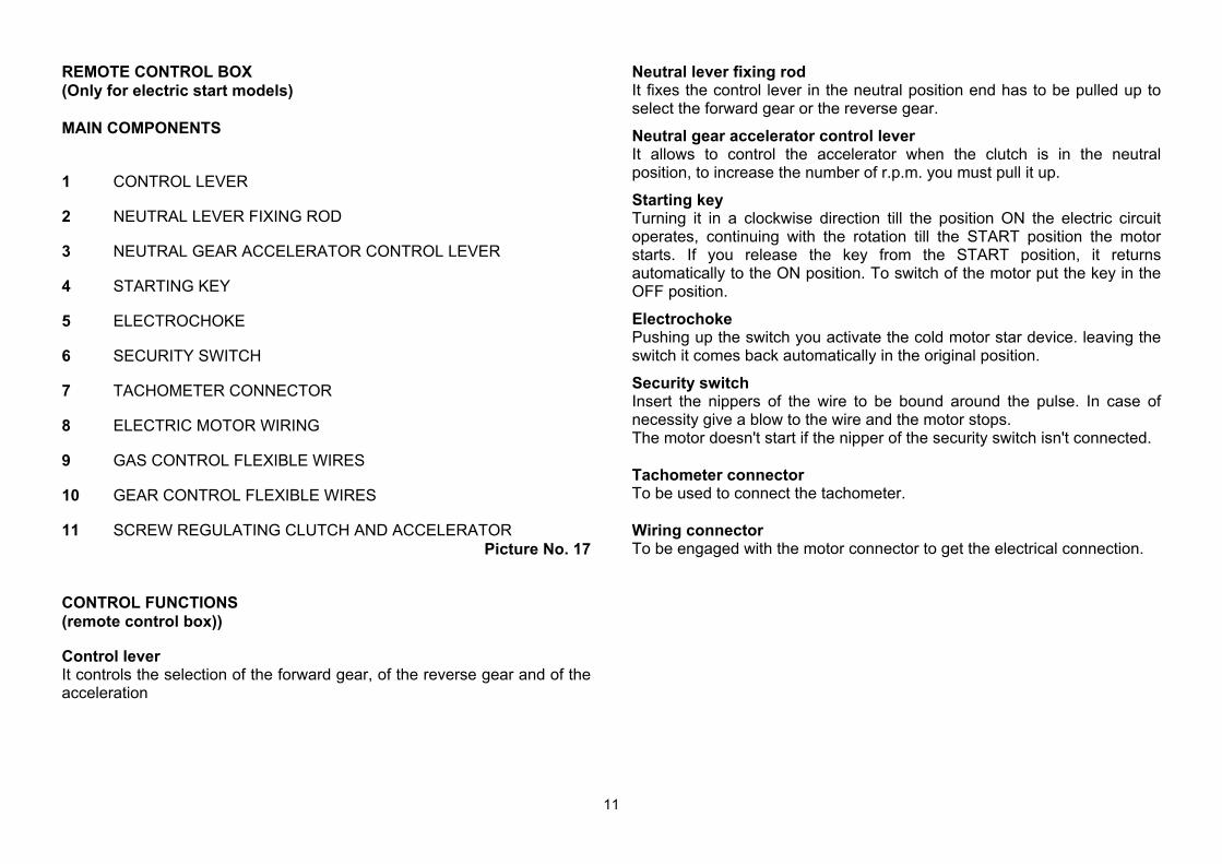
REMOTE CONTROL BOX (Only for electric start models) MAIN COMPONENTS
1 CONTROL LEVER
2 NEUTRAL LEVER FIXING ROD
3 NEUTRAL GEAR ACCELERATOR CONTROL LEVER
4 STARTING KEY
5 ELECTROCHOKE
6 SECURITY SWITCH
7 TACHOMETER CONNECTOR
8 ELECTRIC MOTOR WIRING
9 GAS CONTROL FLEXIBLE WIRES
10 GEAR CONTROL FLEXIBLE WIRES
11 SCREW REGULATING CLUTCH AND ACCELERATOR Picture No. 17
CONTROL FUNCTIONS (remote control box))
Control lever It controls the selection of the forward gear, of the reverse gear and of the acceleration
Neutral lever fixing rod It fixes the control lever in the neutral position end has to be pulled up to select the forward gear or the reverse gear. Neutral gear accelerator control lever It allows to control the accelerator when the clutch is in the neutral position, to increase the number of r.p.m. you must pull it up. Starting key Turning it in a clockwise direction till the position ON the electric circuit operates, continuing with the rotation till the START position the motor starts. If you release the key from the START position, it returns automatically to the ON position. To switch of the motor put the key in the OFF position. Electrochoke Pushing up the switch you activate the cold motor star device. leaving the switch it comes back automatically in the original position. Security switch Insert the nippers of the wire to be bound around the pulse. In case of necessity give a blow to the wire and the motor stops. The motor doesn't start if the nipper of the security switch isn't connected. Tachometer connector To be used to connect the tachometer. Wiring connector To be engaged with the motor connector to get the electrical connection.
12
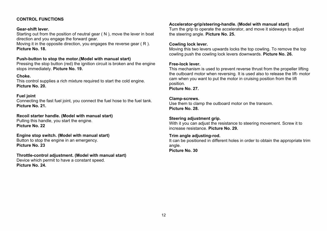
CONTROL FUNCTIONS Gear-shift lever. Starting out from the position of neutral gear ( N ), move the lever in boat direction and you engage the forward gear. Moving it in the opposite direction, you engages the reverse gear ( R ). Picture No. 18. Push-button to stop the motor.(Model with manual start) Pressing the stop button (red) the ignition circuit is broken and the engine stops immediately. Picture No. 19. Choke. This control supplies a rich mixture required to start the cold engine. Picture No. 20. Fuel joint Connecting the fast fuel joint, you connect the fuel hose to the fuel tank. Picture No. 21. Recoil starter handle. (Model with manual start) Pulling this handle, you start the engine. Picture No. 22 Engine stop switch. (Model with manual start) Button to stop the engine in an emergency. Picture No. 23 Throttle-control adjustment. (Model with manual start) Device which permit to have a constant speed. Picture No. 24.
Accelerator-grip/steering-handle. (Model with manual start) Turn the grip to operate the accelerator, and move it sideways to adjust the steering angle. Picture No. 25. Cowling lock lever. Moving this two levers upwards locks the top cowling. To remove the top cowling push the cowling lock levers downwards. Picture No. 26. Free-lock lever. This mechanism is used to prevent reverse thrust from the propeller lifting the outboard motor when reversing. It is used also to release the lift- motor cam when you want to put the motor in cruising position from the lift position. Picture No. 27. Clamp-screws. Use them to clamp the outboard motor on the transom. Picture No. 28. Steering adjustment grip. With it you can adjust the resistance to steering movement. Screw it to increase resistance. Picture No. 29. Trim angle adjusting-rod. It can be positioned in different holes in order to obtain the appropriate trim angle. Picture No. 30
13
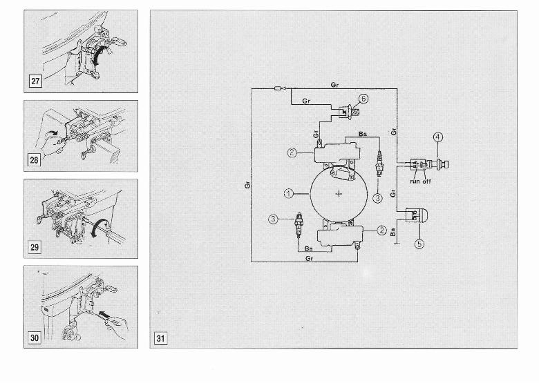
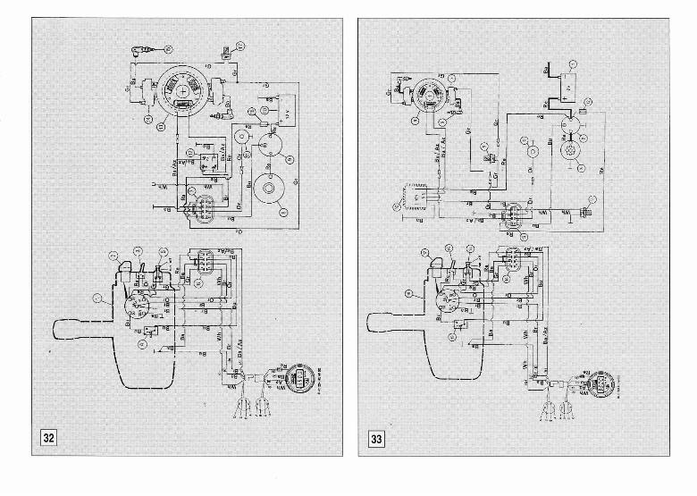
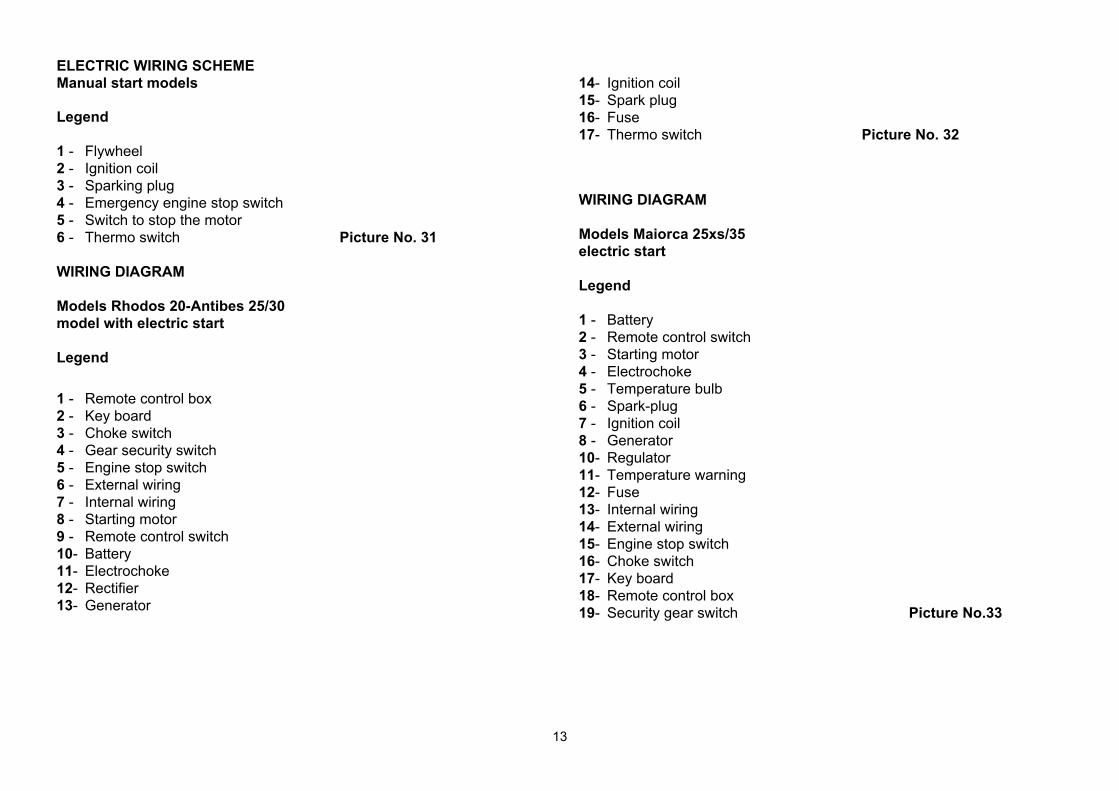
ELECTRIC WIRING SCHEME Manual start models Legend 1 - Flywheel 2 - Ignition coil 3 - Sparking plug 4 - Emergency engine stop switch 5 - Switch to stop the motor 6 - Thermo switch Picture No. 31 WIRING DIAGRAM Models Rhodos 20-Antibes 25/30 model with electric start Legend 1 - Remote control box 2 - Key board 3 - Choke switch 4 - Gear security switch 5 - Engine stop switch 6 - External wiring 7 - Internal wiring 8 - Starting motor 9 - Remote control switch 10- Battery 11- Electrochoke 12- Rectifier 13- Generator
14- Ignition coil 15- Spark plug 16- Fuse 17- Thermo switch Picture No. 32 WIRING DIAGRAM Models Maiorca 25xs/35 electric start Legend 1 - Battery 2 - Remote control switch 3 - Starting motor 4 - Electrochoke 5 - Temperature bulb 6 - Spark-plug 7 - Ignition coil 8 - Generator 10- Regulator 11- Temperature warning 12- Fuse 13- Internal wiring 14- External wiring 15- Engine stop switch 16- Choke switch 17- Key board 18- Remote control box 19- Security gear switch Picture No.33
14
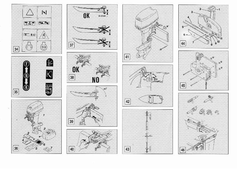
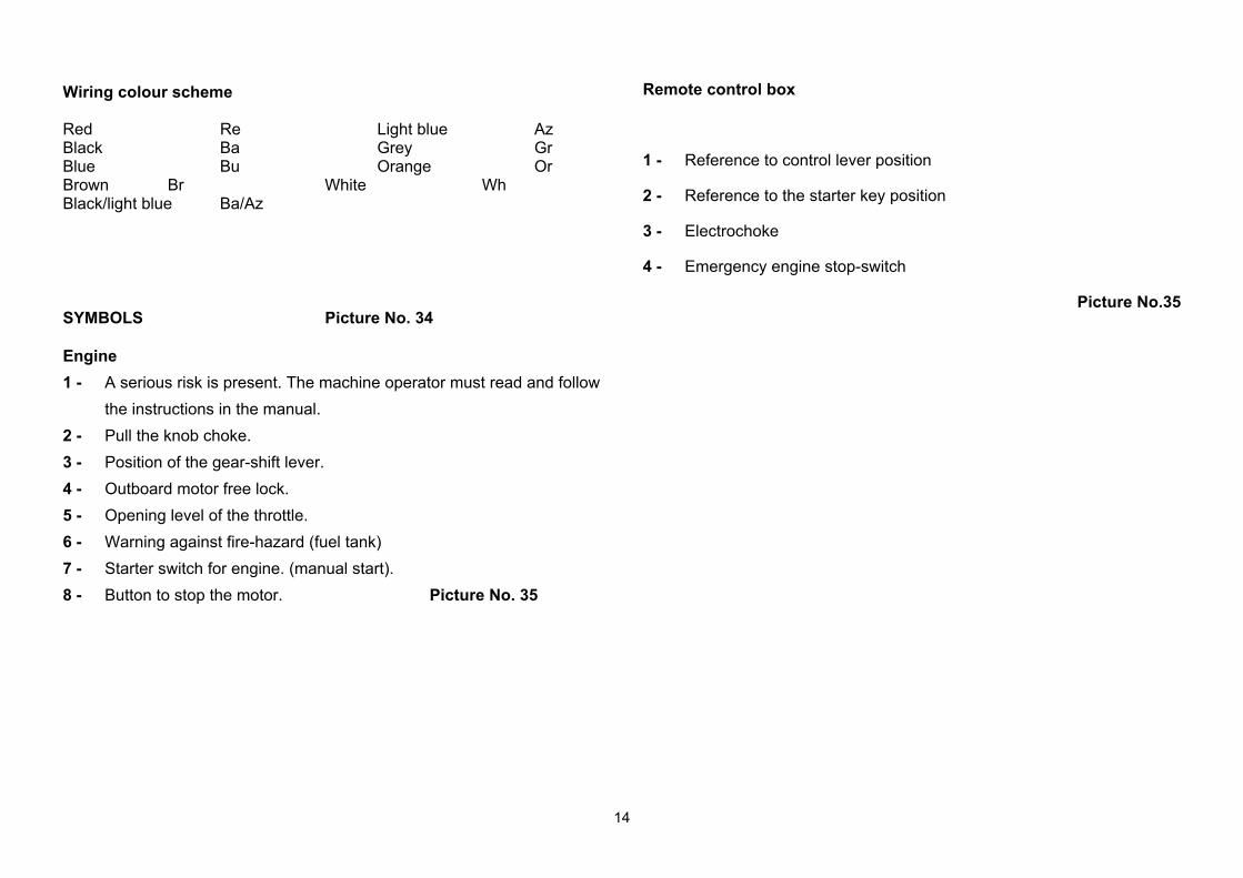
Wiring colour scheme Red Re Light blue Az Black Ba Grey Gr Blue Bu Orange Or Brown Br White Wh Black/light blue Ba/Az SYMBOLS Picture No. 34 Engine 1 - A serious risk is present. The machine operator must read and follow
the instructions in the manual. 2 - Pull the knob choke. 3 - Position of the gear-shift lever. 4 - Outboard motor free lock. 5 - Opening level of the throttle. 6 - Warning against fire-hazard (fuel tank) 7 - Starter switch for engine. (manual start). 8 - Button to stop the motor. Picture No. 35
Remote control box
1 - Reference to control lever position
2 - Reference to the starter key position
3 - Electrochoke
4 - Emergency engine stop-switch
Picture No.35
15
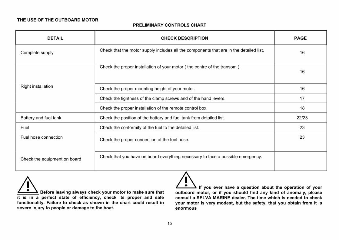
THE USE OF THE OUTBOARD MOTOR PRELIMINARY CONTROLS CHART
DETAIL CHECK DESCRIPTION PAGE
Complete supply Check that the motor supply includes all the components that are in the detailed list. 16
Check the proper installation of your motor ( the centre of the transom ). 16
Right installation Check the proper mounting height of your motor. 16
Check the tightness of the clamp screws and of the hand levers. 17
Check the proper installation of the remote control box. 18
Battery and fuel tank Check the position of the battery and fuel tank from detailed list. 22/23
Fuel Check the conformity of the fuel to the detailed list. 23
Fuel hose connection Check the proper connection of the fuel hose. 23
Check the equipment on board Check that you have on board everything necessary to face a possible emergency.
Before leaving always check your motor to make sure that it is in a perfect state of efficiency, check its proper and safe functionality. Failure to check as shown in the chart could result in severe injury to people or damage to the boat.
If you ever have a question about the operation of your outboard motor, or if you should find any kind of anomaly, please consult a SELVA MARINE dealer. The time which is needed to check your motor is very modest, but the safety, that you obtain from it is enormous
16
Check the supply.
When you receive your motor check that: - the packing is not damaged - the supply corresponds to the detailed list
1 the entire motor
2 remote control box with cables of the Kit k40 (only for models with electric start)
3 steering control rod with bolts and nuts (only for models with electric start)
4 fuel tank supplied complete with the fuel hose and quick reverse connection
5 tool- bag
6 use and maintenance manual
7 certificate of guarantee 8 declaration of conformity E.E.C. 9 list of dealers and our after-sales service
- there is no evident damage. If there is a damage or parts are missing, you must inform immediately and in details the forwarding-agent, SELVA joint stock Co. or its area agents.
Picture No.36
Outboard motor mounting.
A good position of the motor on the transom is very important to have an appropriate trim angle and therefore to obtain a good performance from your boat To have the optimum mounting height of the outboard motor, you must mount it so that the anti-cavitation plate is between the bottom of the boat and a level of 2 cm below it and it is parallel to it.
If the mounting-height is too high, cavitation tends to occur and consequently there will be a falling-off in the performance and a probable overheating of the motor. If the mounting-height is too low, the water-resistance will increase and thereby reduce engine efficiency.
Picture No. 37
The motor must be vertical to the water surface and the bracket mounted on a flat even surface and should be fully supported by the top edge of the transom. If the bracket is not fully supported or, if the transom height is too low, a hard wood block should be securely fitted between the bracket and the transom.
Picture No. 38
17
Trim angle adjusting The trim angle is the inclination angle, that should be given to the motor in order to obtain an optimal performance from your boat.
An improper trim angle does not only affect the performance of your boat, but can also cause loss of control, which means danger for the people on board.
While sailing the motor should be perpendicular to the water surface, but the trim angle can be 3 degrees to 5 degrees. If the trim angle is made too great, the buoyancy centre of the boat will shift towards the stern. In this condition, and if the stability moment at the bow is large, the boat will tend to "porpoise". If the trim angle is insufficient, the bow may "plough", making the boat unstable. When the boat is in stable trim it remains parallel to the water. To adjust the trim angle proceed as follows:
- push down the free-lock lever and tilt up the motor till the
first automatic stop; - remove the adjusting-rod and reposition it in the position
which allows the appropriate trim angle; - slightly tilt up the motor, unlock the tilt up lever, pushing it
upwards and bring the motor back to the vertical position.
Improperly distributed load on boat or in different positions, can alter the ideal trim conditions.
You must adjust the trim angle when the engine is switched off. Picture No. 39
Ensure the transom clamp screws are tightened securely Picture No. 40
18
OUTBOARD MOTOR FIXING
After having made all the operations of adjusting the trim-angle, make two holes in the transom so that they correspond to the holes of the fixation bracket. Put a layer of dope on the holes and on the screws to be used to fix (which are with the motor). Put the motor on the transom and fix it, paying attention that the fixing nuts must be inside the boat. Control the tightening of nuts and levers.
Use only bolts, nuts and washers which are in the motor packing. If you need to use other components, be sure that they are of the same quality regarding the material and strength. Tighten the bolts and check the tightning of bolts and levers after running the motor. Picture No.41 REMOTE CONTROL BOX INSTALLATION
To install the remote control box and the cables we suggest you contact an official dealer SELVA MARINE. We suggest you contact this dealer also for the control device installation.
An improper installation of a remote control box may cause a sudden and unexpected loss of control, of the boat. In case or doubts about the remote control installation, ask your SELVA MARINE dealer.
Position of the remote control box
Normally the remote control box is supplied to be in positioned on the right. If you need to have it on the opposite side, ask your dealer. When positioning the remote control box pay attention that the control lever can be gripped and operated comfortably and without obstacles. Even the cables must be put in order not to have any obstacle on their patch and must not get in the way of the passengers. Be sure that the cables are long enough and that they can't get entangled when the steering-wheel is operating. Picture No. 42
If the cables aren't correctly installed, they can get entangled causing the loss of control of the boat.
19
Never bind or entangle the cables of the remote control box. They mustn't be bound with a bending ray inferior to 300 mm. (12 feet).
The cables must be of the type C-2. Picture No.43 CONNECTION OF THE CABLES OF CONTROL Side of the remote control box To connect the control cables to the box you have to follow the following instructions: ß Remove the lower cover (6) of the remote control box by unscrewing
the two screws. ß Put the control lever (1) in neutral position. ß Screw completely the gear to connect the remote control box (9) to
the threaded extremity of the cables and fix them with the counter-nut, paying attention not to tighten it too much.
ß Put the head of the gear-control lever in the pawl of the gear lever (10) and insert the retaining ring (8).
ß Insert the head of the gas-control cable in the pawl of the accelerator lever (11) and insert the retaining ring.
ß Fix the sheathing of the cables inserting the sheathing-retainer in its
housing.
ß Screw the lower cover. Picture No. 44
Remote control box fixation After having connected the remote control cables, put the box in the foreseen position and fix it with the screws. Picture No.45 Connection side of the motor Kit k40 To connect the control cables to the motor you have to use the kit k40 which is composed by:
1 sheathing retainer (2 parts) 2 connection for gears handle 3 connection for plate control gas 4 plate to fix the sheathing-retainer (2 parts) 5 cotter pin to fix the sheathing (2 parts)
20
ß Fix the plate to the (4) handle or to the plate in correspondence
of the holes (using the screws which are in the kit k40). The plate must be fixed in order to allow the insertion of the retainer (1) beginning from up to down.
ß Insert the sheathing retainer on the cables (1) ß Screw the counter-nuts (accessories of the Kit K40) to the end
of the threaded part of the control cables ß Screw completely the gas plate connector (3) to the
accelerator control ß Insert the sheathing retainer in the fixation plate, control if
connecting the connector (3) in the pawl of the plate of control of the accelerator, the housing of the cotter pin is in correspondence of one of three holes in the sheathing retainer.
In contrary case unscrew the plate connector to achieve the correct position.
ß Insert the same connector in the plate of control of the
accelerator, and ensure the connection through the gripping of the spring fixed on the plate connector.
ß Insert in the hole of the sheathing retainer, that corresponds to
the housing of the same sheathing, the fixing cotter pin (5).
ß Screw the other fixation plate sheathing retainer to the basin in correspondence of the holes which are on one side of the gears handle. Insert in the plate the sheathing retainer mounted on the cables of the gears control.
ß Screw completely the gears handle connector on (2) the gears control cables and make the regulation of the distance between the sheathing retainer and the gear control handle for the gas control cable.
ß Insert the pin on the connector of the gears handle in the
housing which is on the same handle, push the ring nut of the pin and rotate the pin to put the retainer of the pin on the beat of the handle.
ß Insert in the sheathing retainer hole, which corresponds to the
housing of the sheathing, the fixing cotter pin (5). ß Fix the position of the gears handle connectors and of the gas
plate with the counter-nuts Picture No.46
Control at the end of the operations the correct functioning of the remote control box.
21
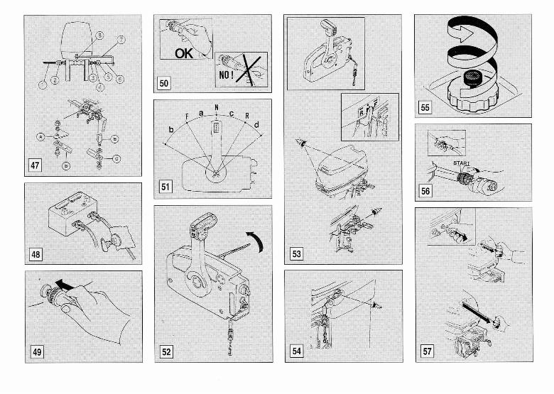
STEERING CONTROL DEVICE MOUNTING Insert the control cable in the tube brackets union. Fix one extremity of the longitudinal rod of control of the steering to the steering fixation plate, using the apposite nut, bolt and washer. Then fix the other extremity of the rod to the cable of control through the nut and the washers. Insert the sheet-retainer 2 in the control cable. Insert the cable in the tube brackets union, then on the cable itself and then the washer 4 and the ring 5. Stop the sheet in the bracket tube screwing the rings 2 and 5 completely (see the positions of the bolts shown in the picture). Picture No. 47 1 Control cable 2 Ring 3 Tube bracket union 4 Washer 5 Ring nut 6 Control cable end 7 Steering link arm kit 8 Steering plate
A Steering plate
B Steering arm kit
C Control cable end
Picture No.47
22
BATTERY MOUNTING Connecting the battery
Before connecting or disconnecting the battery leads turn the switch key in the anti-clockwise direction, to avoid risks of electric shock, fire or explosion.
It is important to install with the battery the battery disconnect switch. (not included) Mount the battery in a dry, well-ventilated, vibration-free location in the boat.
Recommended battery type: 12V 40 AH (144 kC) Connect the red lead to the positive terminal(+) first; then connect the black lead to the negative terminal(-). 1 - Red lead 2 - Black lead 3 - Battery 4 - Battery disconnect switch Picture No. 48 To disconnect the battery, disconnect the black lead first.
Battery electrolytic fluid is dangerous; it contains dilute sulphuric acid and therefore is poisonous and highly caustic Always follow these preventive measures:
• Avoid bodily contact with electrolytic fluid as it can cause severe burns or permanent eye injury.
• Wear protective eye gear when handling or working near batteries. • If any battery electrolytic fluid spills onto your skin,flush with water. • If you should get battery electrolytic fluid in your eyes flush with
water for 15 minutes and get immediate medical attention. • If you should swallow battery electrolytic fluid, drink large quantities
of water or milk followed by milk of magnesia, beaten eggs or vegetable oil. Get immediate medical attention.
Batteries also generate explosive hydrogen gas. Therefore avoid operating in areas which are not well-ventilated or near fire, spark, or open flames. DO NOT SMOKE when charging or handling batteries. KEEP BATTERIES AND ELECTROLYTIC FLUID OUT OF REACH OF CHILDREN.
23
FUEL
Fuel The fuel used for the propulsion of internal combustion engines is highly flammable and, in certain cases can become explosive. Refuelling and maintenance operations must be done in a well-ventilated area and with the engine stopped. Do not smoke while refuelling, keep away from sparks, flames, or other sources of ignition, which could cause fire or explosion. Do not spill gasoline. If gasoline spills, wipe it immediately with dry rags, before starting the motor . Do not overfill the fuel tank, because gasoline expands with the heat and the sun radiation. Tighten the filler cap securely after refuelling. Do not let gasoline get into your eyes or onto your skin. Avoid swallowing gasoline or inhaling its vapour. Do not pour fuel off using a pipe. If you should swallow some gasoline, inhale a lot of gasoline vapour, get some gasoline in your eyes, or if any gasoline spills onto your skin, get immediate medical attention. Keep out from children reach.
Preparation of the fuel
Use only petrol with a octane number higher than 95 N.O. Research and that does not contain alcohol, with the addition of 2% of oil proper for mixture (see the detailed list)
Pour first the oil and then the petrol into the fuel tank, then mix the fuel thoroughly by shaking. It is a good custom, if you use the motor after a break longer than one day, to shake the fuel tank in order to mix oil and petrol thoroughly.
Fuel tank clamping and pipes connection Put the fuel tank horizontally in the hull, anchored to the bottom, in a place where it does not hinder your movements and so that the pipe is long enough to reach the motor. Then connect the pipe to the fuel joint. For this operation you have to insert the female fast fuel connector. Picture No. 49 Now you have to check the full connection, is secure pulling lightly the joint (do not pull grasping the hose). Picture No. 50 To release it is enough to pull the ring nut of the fast connector.
24
USE OF THE REMOTE CONTROL BOX
Leaving from the position N of the control lever, to position in forward gear you have to lift the retainer lever and to put the control lever in position F. The insertion of the gear is indicated by a release of the movement. if the lever goes on in its travel, the accelerator begins to operate. At the end of the travel of the lever there is the maximum opening of the throttle valve. To select the reverse gear you have to put the control lever in position R . If, when the gear is selected, the lever goes on in its travel, the acceleration phase begins N Neutral position (neutral) F Forward gear (forward) R Reverse gear (reverse) a Travel to select the forward gear b Acceleration travel if forward gear is selected c Travel to select reverse gear d Acceleration travel if reverse gear is selected Picture No. 51
The travel of the acceleration when the reverse gear is selected is mechanically limited on the motor. To avoid damages not to force on the control lever.
Accelerating when neutral gear is selected To open the throttle when the neutral gear is selected (gear lever in N position), you have to use the neutral gear lever and turn it up. Picture No. 52
Before selecting the gear you always have to put the gas lever at the neutral position, in repose position (completely down)
The gas lever can be actionned only when the control lever is in position N. The control lever can be actionned only when the gas neural control lever is at repose position (completely down).
The micro switch 8 prevents the motor from starting when the gear is selected. Even the manual starting models have a mechanical device that prevents the starting when the gear is selected.
25
STARTING Controls before starting the motor
Check that the top cowling is locked, that the free-lock mechanism is in the lock position and that the gear-shift lever is in the neutral position ( N )
Picture No. 53.
Make sure that the lock plate is installed on the engine stop switch. Picture No. 54.
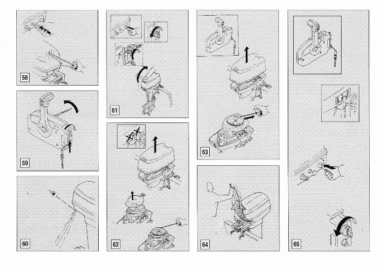
Starting procedures with cold motor Loosen the safety valve on the fuel tank. Picture No. 55 Fill up the carburettor with fuel using the little hand pump ( you have primed the carburettor, when the pump bulb has become firm ). Place the throttle-grip in the "start" position. Picture No. 56. Model with manual start Pull out the choke knob Pull the starter-handle slowly so that the starter pinion engages with the flywheel. Then give a strong pull, but not too strong, and repeat if necessary the procedure if the motor does not start. Picture No. 57. Set the choke knob to home position. . Pull the starter-handle powerfully until the engine starts. Picture No. 58. Models with electric start Check that the control lever (remote control box) is at position N. Turn up the gas control lever at neutral position. Pushing up the choke control lever and turn the starting key, keeping it in the position ON for 5 no more than five seconds. When the motor starts, release the key, the choke switch
and let down the gas control lever at neutral. Picture No. 59
When the engine is still warm, you don't need to use the choke knob. Should the engine fall to start after many attempts, refer to the section on troubleshooting.
Verifications when the motor is on
Just after starting the motor, you should make sure that :
- after 5/10 seconds, water runs out from the cooling-water pilot-holes. The indicator at the entrance of the circuit, provides only for the proper operation of the pump and not for the circulation of water in the head and in the cylinder. That means that possible shortages will not be indicated. If water does not flow from the pilot-holes check to see if the water-inlets are blocked. Picture No. 60; - that you do not hear any strange noise; - that the throttle-grip operates in a proper way; - that the gear shift lever operates properly and that with the reverse
gear selected the motor does not tilt; - that the engine stop switch operates properly;
26
CRUISING Responsibility during the navigation. The operator is responsible for the proper running of the boat and for the safety of the people on board. Everybody must read this manual before cruising. Show all the passengers the location of the safety equipment and the way to use it. Teach one of your passengers , how to pilot the boating an emergency. Familiarise yourself with the laws and regulations in force where you want to sail. Tilt-up the motor To tilt up the motor do as follows: n Switch off the engine. n Lift the free lock lever n Lift the motor using the apposite handle till the achievement of the
mechanical stop. n To bring it back to the cruising position, you just have to let down the
anti-tilt hook, let down the lilt-hook to the mechanical stop. Picture No. 61
Overheat warning system
The engine is provided with an overheat warning device Before the engine becomes too hot, the engine speed fall suddenly (as a matter of fact this device leaves out the connection of a ignition-coil).
If the overheat warning system operates, proceed as follows: Check that water runs out of the pilot hole. If OK, keep the engine at low speed for about five minutes. Then avoid overloading the engine. If no water or just a little runs out from the pilot hole, stop the engine, tilt it up, as shown in this manual and check the water inlets for blockages. If blocked, you must clean them, bring the motor back to the home position and start it and run it at low speed for about five minutes; check that water runs out of the pilot hole. If after having done all this, you start the engine and no water runs out of the pilot hole, stop immediately the motor and contact a SELVA MARINE dealer.
Always switch the engine off, before tilting it up. Once you have brought the motor back to the cruising position, lock the free-lock lever, before starting sailing again.
Do not keep the engine running, if no water runs out of the pilot hole.
27
EMERGENCY STARTING PROCEDURES If the motor doesn't start because of a damage at the starting system, it is possible to use the emergency starting cable. Models with manual start
When starting the motor with the emergency starter rope, the security device against starting when the gear is selected doesn't work. Be sure that the gear lever is at neutral position N; in different case, the boat might roll continuously during the starting, causing serious damages to the people on board.
Procedure 1 Put the gear lever at neutral position 2 Take away the cover using the levers 3 Take away the flywheel cover unscrewing the two screws 4 Insert the extremity of the cable positioning it with the knot in the
groove of the flywheel rotor, wind the cable one or two turns in a clockwise direction
5 Pull it to let the motor start. Repeat if necessary Picture No.62
Models with electric start 1 Put the control lever on N 2 Turn the starting key on the position ON 3 Take away the cover using the levers 4 Insert the extremity off the cable positioning it with the knob in the
groove of the flywheel rotor, wind the cable one or two turns in a clockwise direction
5 Pull it to let the motor start. Repeat if necessary Picture No.63
In case of electric start motors it's not possible to start the motor if the control lever isn't at the neutral position and the starting key isn't at ON position.
During the starting procedures or during the functioning of the motor don't touch the ignition coil, the high-voltage cable, the spark-plug cap or any other electrical parts at high voltage. Before pulling the emergency starting cable be sure that clothes or other objects can't get entangled in the engine. The flywheel, when operating, is very dangerous. Never try to put on the cover when the motor is operating. Go to the nearest port where you can have your motor repaired as soon as possible. Be sure that the flywheel is safe from the sprinkles of water.
28
RUNNING-IN PROCEDURE A SELVA outboard motor is tested completely in our workshop and it is partially run in a tank. A second test is done by the concessionaire It is always advisable to complete the running in procedure in the following way:
. During the first 15 running hours you must use a fuel with oil at 3%.
During the first 3 running hours do not accelerate too much, and during the following hours you can accelerate properly but only for short periods. After about 20 hours you have to change entirely the gearbox-oil (see the greasing sectioning this manual).
This running in procedure will allow you to obtain the best performance from your motor and longer endurance.
STOPPING PROCEDURE
Emergency stopping procedures.
In an emergency you can stop your motor by pulling the engine stop switch lanyard.
To start the motor again you have to install again the lanyard's lock plate on the engine stop switch. Picture No. 64.
Stopping in normal conditions Place the gear-shift lever in the neutral position " N " (neutral gear); accelerate light in order to avoid flooding, run the engine again at idling speed and then push the stop button,(for model with manual start). Turn the switch key in the anti-clockwise direction, (for model with electric start). Picture No. 65.
29
Stopping for a long period of storage.
If you will not use the motor for several days, you should stop the engine in the following way: Run the engine at idling speed, place the gear-shift lever in the neutral position "N" and keep the choke knob pulled until the engine stops.
CLEANING Cleaning outside SELVA motors don't need much cleaning; to clean the painted parts use a cloth soaked with water.
Do not use flammable solvents. Cleaning cooling-water passages Every now and then after using, clean the cooling-water passages, in order to remove mud and salt, so that they do not affect the performance of your motor.
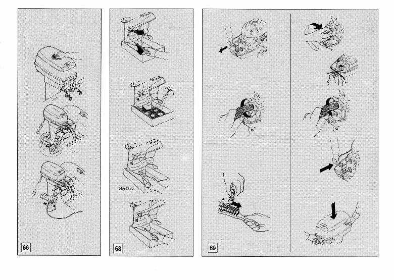
You can carry out this cleaning operation in two different ways: 1 - Immerse the outboard motor without the propeller in a tank filled up with fresh-water, make sure that the water level is over the height of the water inlets, so that no irreparable damage could be caused to the motor. Shift the gear-shift lever into neutral " N ". Start the engine and run at low speed for a few minutes. 2 - Connect a pipe of fresh-water to the hole for the engine cleaning joint plug ( use the proper joint available in the fittings series ). Stop the water inlets. Shift the gear-shift lever into neutral. Start the engine and run at low speed for a few minutes.
While cleaning the cooling water passages make sure that water always circulates in the passages, checking its running out of the pilot hole. Picture No. 66
30
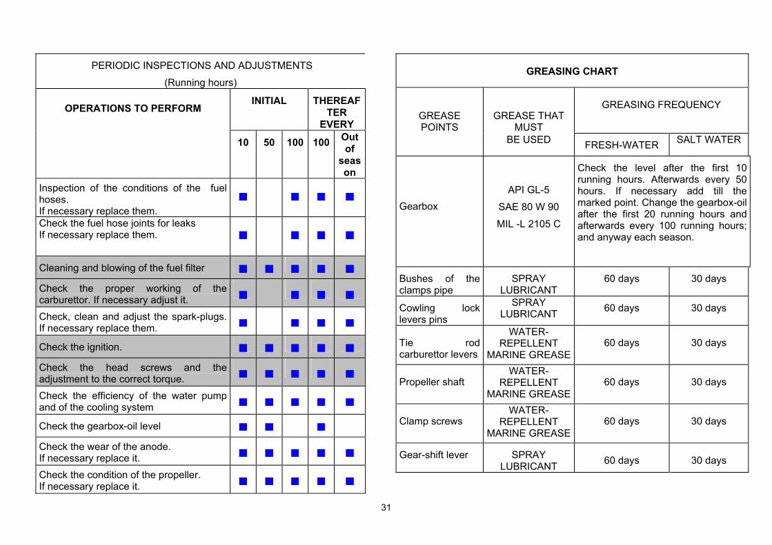
MAINTENANCE Before doing any kind of maintenance or check operation, switch off the engine and wait till it has cooled down, then remove the spark plug cap, in order to avoid an accidental starting. Pay attention to the motor parts, which are still hot, so that you do not burn yourself. Some maintenance operations must be carried out by qualified staff. Contact SELVA MARINE after-sale service. The following chart lists the periodic maintenance operations to do on your motor.
The pointed out operations must be done by qualified staff.
31
PERIODIC INSPECTIONS AND ADJUSTMENTS (Running hours)
OPERATIONS TO PERFORM INITIAL THEREAF
TER EVERY
10 50 100 100 Out of
season
Inspection of the conditions of the fuel hoses. If necessary replace them.
Check the fuel hose joints for leaks If necessary replace them.
Cleaning and blowing of the fuel filter
Check the proper working of the carburettor. If necessary adjust it.
Check, clean and adjust the spark-plugs. If necessary replace them.
Check the ignition.
Check the head screws and the adjustment to the correct torque.
Check the efficiency of the water pump and of the cooling system
Check the gearbox-oil level
Check the wear of the anode. If necessary replace it.
Check the condition of the propeller. If necessary replace it.
GREASING CHART
GREASE POINTS
GREASE THAT MUST
GREASING FREQUENCY
BE USED FRESH-WATER SALT WATER
Gearbox API GL-5
SAE 80 W 90 MIL -L 2105 C
Check the level after the first 10 running hours. Afterwards every 50 hours. If necessary add till the marked point. Change the gearbox-oil after the first 20 running hours and afterwards every 100 running hours; and anyway each season.
Bushes of the clamps pipe
SPRAY LUBRICANT
60 days 30 days
Cowling lock levers pins
SPRAY LUBRICANT 60 days 30 days
Tie rod carburettor levers
WATER-REPELLENT
MARINE GREASE60 days 30 days
Propeller shaft WATER-
REPELLENT MARINE GREASE
60 days 30 days
Clamp screws WATER-
REPELLENT MARINE GREASE
60 days 30 days
Gear-shift lever SPRAY LUBRICANT 60 days 30 days
32
Greasing and additions The only part, which must be filled with oil, is the gearbox. Selva supply the motor already with the oil, which the user will have to change completely after the first 20 cruising hours After this change you must check its level every 50 hours and change it every 100 hours, and anyway each season. Gearbox-oil change To change the oil do as follows : Keep the motor in vertical position. Place a container to collect the used oil under the gearbox. Take out the oil-level plug and the oil drain-plug.
They have a different size and after the oil change they must be replaced in their proper seat.
Wait until the oil has drained completely, (during this operation you must check, if water or other foreign bodies are to be found in the drained oil. They are signs of anomalies which must be identified and repaired by qualified staff, before using the motor again). Protecting the leaning parts, put the motor horizontally, with the oil-level plug and the oil drain-plug holes upwards. Inject the oil into the oil drain-plug hole.
The oil must agree with the characteristics listed in the greasing chart, and must comply with the quantity pointed out in the technical detailed list.
Insert and tighten the oil-level plug and the oil drain plug. Picture No. 68.
The used oil must be given to the proper collecting centres or to a SELVA service point.
Spark-plugs The spark-plug must be often inspected because heat and deposits affect its efficiency so that the performance of the motor will be affected too.
The inspection of the spark-plug must be done when the engine is not running and it has cooled down. It is very important to check, that the part made of porcelain is not damaged because this could allow external sparks, which could lead to explosion or fire.
To remove the spark-plug use the supplied spanner; using an abrasive brush, remove any depots, then check the wear condition and the spark-plug gap ( the gap must be 0,6 mm, to measure it use a thickness gauge ) . If the spark-plug is badly worn you must replace it with a new one which must agree with the characteristics listed in the specifications chart.
33
The spark-plug torque is 20 Nm ( ~ 2. kgm). If a torque-wrench is not available, you can obtain a good estimate of the correct torque turning the spark-plug completely by hand and then turning it with the spanner, a new spark-plug must be turned ~ 90° and an old one 15° ÷ 20°. Replace the spark-plug cap, checking that it is correctly fitted and then replace the top cowling. Picture No. 69
Sacrificial anode. To protect the motor against electrochemical corrosion, due to the presence in its structure of many different materials, a sacrificial anode has been applied. The anode will be subject to a strong corrosion, so you have to remove the scales from the surfaces of the anode periodically.
Failure to clean it, will affect its effectiveness.
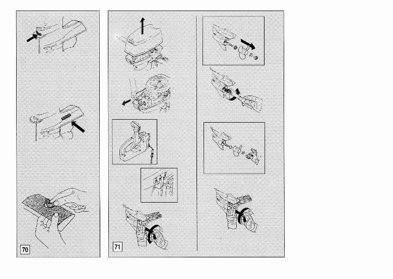
Do not paint the anode, for this would render it ineffective. When the corrosion compromise its functionality, you have to replace it. Picture No.70.
Replacement of the propeller. The propeller is one of the components, which have a great influence upon the performance of the motor. An unsuitable or damaged propeller can cause serious damages to the motor besides reduce the performance. For an careful choice of the propeller consult a SELVA MARINE service centre. Remove and replace the propeller do as follows: - wait until the motor has cooled down and remove the top cowling;
- remove the spark-plug cap, to avoid an accidental start during the operations of replacement of the propeller;
- place the gear-shift lever in the neutral position " N "; - protect your hands using strong gloves and insert a wooden lump
between the propeller blades and the anti-cavitation plate, to keep the propeller still.
- remove the self stopping nut, the internal shoulder, the propeller and the external shoulder;
- spread the propeller shaft with water-repellent grease; - by hand insert the internal shoulder, the propeller and the external
shoulder; - by hand screw the self-locking nut; - insert a wooden lump between the propeller blades and the anti-
cavitation plate. - keep the propeller pressed against the pin and screw tight the nut.
Picture No. 71. Towing
34
The motor should be towed in the normal running position. Avoid towing with the tilt-support lever only, but use a motor support device.
Storage
To help the endurance of your motor, you must carry out properly the following storage operations:
Clean the motor and the cooling-water passages. Switch off the engine as shown in the section "stopping for a long period of storage ". Remove the fuel-line connections from the motor. Clean the fuel filter. Empty the float chamber. Remove the spark-plug and pour engine-oil into the hole; turn the flywheel by hand to distribute the oil in the cylinder; replace the spark-plug.
Change the gearbox-oil. Check the screws torque. Grease all the components as shown in the greasing chart. Inspect the anode. Store the motor in vertical position, in a dry and not too cold place.
The operations of storage must be done by qualified staff. Fuel tank. Store the fuel tank in a well-ventilated place, not in direct sunlight.
For a long period of storage, drain the fuel from the tank
Battery Disconnect both battery leads from the battery, disconnecting the black lead from the negative terminal first. Store the battery on a level surface in a dry, cool, well-ventilated, out of direct sunshine.
Follow the battery manufacturer's instructions.
,oo'
35
TROUBLESHOOTING
A regular maintenance can help you prevent many problems with your outboard motor.
The following chart lists some common difficulties and their possible causes.
If you still have difficulties, after investigating these, please contact your SELVA MARINE dealer.
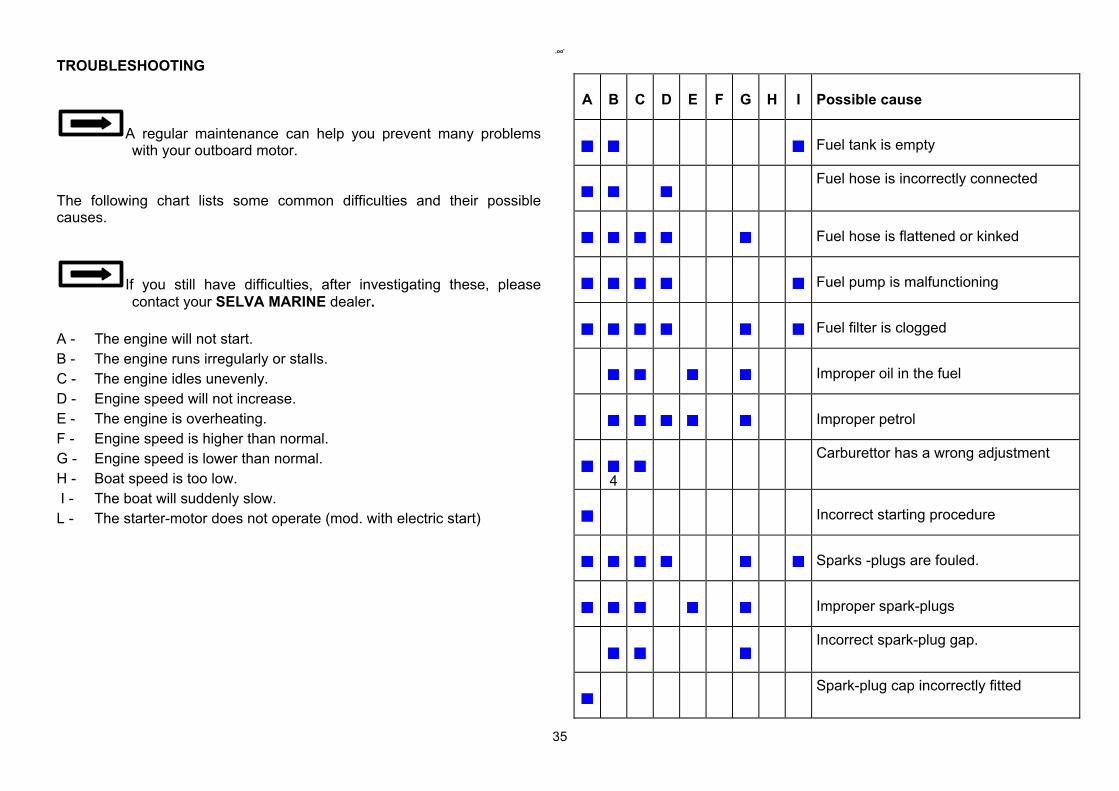
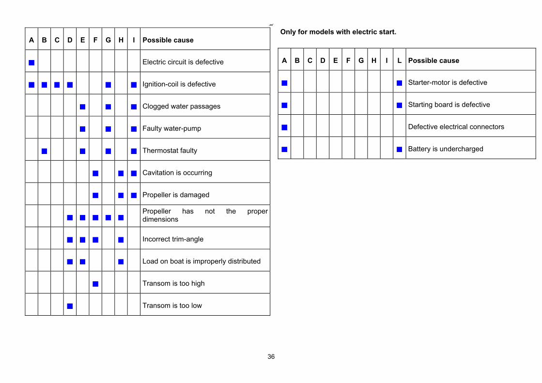
A - The engine will not start. B - The engine runs irregularly or staIls. C - The engine idles unevenly. D - Engine speed will not increase. E - The engine is overheating. F - Engine speed is higher than normal. G - Engine speed is lower than normal. H - Boat speed is too low. I - The boat will suddenly slow. L - The starter-motor does not operate (mod. with electric start)
A B C D E F G H I Possible cause
Fuel tank is empty
Fuel hose is incorrectly connected
Fuel hose is flattened or kinked
Fuel pump is malfunctioning
Fuel filter is clogged
Improper oil in the fuel
Improper petrol
4
Carburettor has a wrong adjustment
Incorrect starting procedure
Sparks -plugs are fouled.
Improper spark-plugs
Incorrect spark-plug gap.
Spark-plug cap incorrectly fitted
,oo'
36
A B C D E F G H I Possible cause
Electric circuit is defective
Ignition-coil is defective
Clogged water passages
Faulty water-pump
Thermostat faulty
Cavitation is occurring
Propeller is damaged
Propeller has not the proper dimensions
Incorrect trim-angle
Load on boat is improperly distributed
Transom is too high
Transom is too low
Only for models with electric start.
A B C D E F G H I L Possible cause
Starter-motor is defective
Starting board is defective
Defective electrical connectors
Battery is undercharged