Embed Size (px)
Citation preview
Owner’s Manual
DCAC
AC & BATTERYPOWERED
FET
Thank you, and congratulations on your choice of BOSS AC-3 Acoustic Simulator.
Before using this unit, carefully read the sections entitled: “USING THE UNIT SAFELY” and “IMPORTANT NOTES” (separate sheet). These sections provide important information con-cerning the proper operation of the unit.
Additionally, in order to feel assured that you have gained a good grasp of every feature pro-vided by your new unit, this manual should be read in its entirety. The manual should be saved and kept on hand as a convenient reference.
A battery is supplied with the unit. The life of this battery may be limited, however, since its primary purpose was to enable testing.
Copyright © 2006 BOSS CORPORATIONAll rights reserved. No part of this publication may be reproduced in any form without the written permission of BOSS CORPORATION.
2
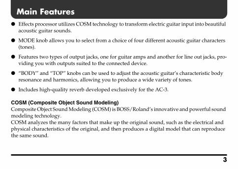
Main Features
Effects processor utilizes COSM technology to transform electric guitar input into beautifulacoustic guitar sounds.
MODE knob allows you to select from a choice of four different acoustic guitar characters (tones).
Features two types of output jacks, one for guitar amps and another for line out jacks, pro-viding you with outputs suited to the connected device.
“BODY” and “TOP” knobs can be used to adjust the acoustic guitar’s characteristic body resonance and harmonics, allowing you to produce a wide variety of tones.
Includes high-quality reverb developed exclusively for the AC-3.
COSM (Composite Object Sound Modeling)Composite Object Sound Modeling (COSM) is BOSS/Roland’s innovative and powerful sound modeling technology. COSM analyzes the many factors that make up the original sound, such as the electrical and physical characteristics of the original, and then produces a digital model that can reproduce the same sound.
3
Panel Descriptions
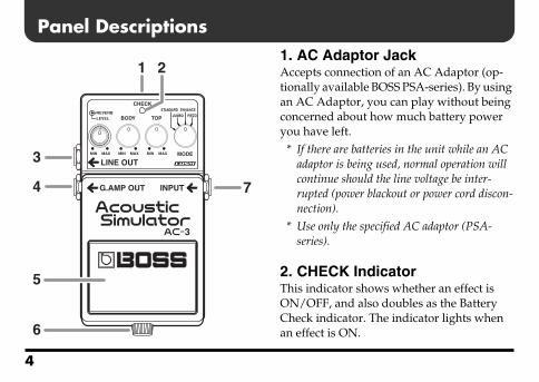
fig.01 1. AC Adaptor JackAccepts connection of an AC Adaptor (op-tionally available BOSS PSA-series). By using an AC Adaptor, you can play without being concerned about how much battery power you have left.
* If there are batteries in the unit while an AC adaptor is being used, normal operation will continue should the line voltage be inter-rupted (power blackout or power cord discon-nection).
* Use only the specified AC adaptor (PSA-series).
2. CHECK Indicator This indicator shows whether an effect is ON/OFF, and also doubles as the Battery Check indicator. The indicator lights when an effect is ON.
3
1 2
74
5
6
4
Panel Descriptions
* If this indicator goes dim or no longer lights while an effect is ON, the battery is near exhaustion and should be replaced immedi-ately. For instructions on changing the battery, refer to “Changing the Battery” (p. 16).
* The CHECK indicator shows whether the effect is being applied or not. It does not indicate whether the power to the device is on or not.
3. LINE OUT JackThis output jack is used for connecting to mixers, recorders, and other devices that ac-cept line-level input.When a cable is also connected to the G.AMP OUT jack, the output is sent from the LINE OUT jack when the effect is switched on, while the output is muted when the effect is switched off.For details, see “Connections” (p. 8–p. 13).
4. G.AMP (Guitar Amp) OUT JackThis output jack is used for connecting to guitar amps and other effects processors.The effect sound or direct sound is output from here depending on whether the effect is switched on or off.When a cable is simultaneously connected to the LINE OUT jack, the output from the G.AMP OUT jack is muted when the effect is switched on, while the direct sound is output when the effect is switched off.For details, see “Connections” (p. 8–p. 13).
5. Pedal SwitchThis switch turns the effects on/off.
5
Panel Descriptions
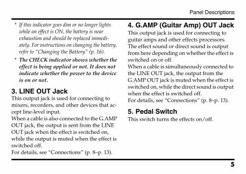
6. ThumbscrewWhen this screw is loosened, the pedal will open, allowing you to change the battery.
* For instructions on changing the battery, refer to “Changing the Battery” (p. 16).
7. INPUT JackThis jack accepts input signals (coming from a guitar, some other musical instrument, or another effects unit).
* The INPUT jack doubles as power switch. Power to the unit is turned on when you plug into the INPUT jack; the power is turned off when the cable is unplugged. When not using the effects unit, be sure to disconnect the plug from the INPUT jack.
fig.02
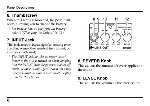
8. REVERB KnobThis adjusts the amount of reverb applied to the sound.
9. LEVEL KnobThis adjusts the volume of the effect sound.
11 128 9 10
6
Panel Descriptions
10. BODY KnobThis adjusts the resonance of the sound pro-duced by the guitar body, altering the char-acteristic mellowness and breadth of the acoustic guitar sound.
11. TOP KnobThis adjusts the sense of attack and the har-monic content of the upper range.
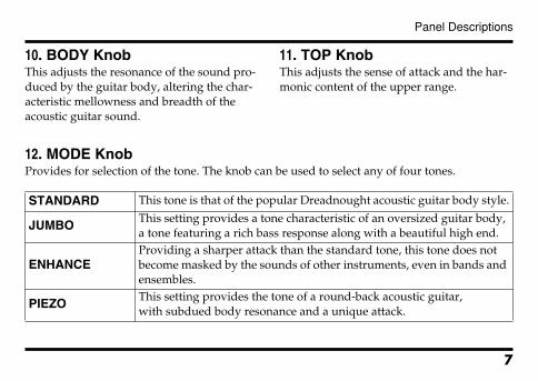
12. MODE KnobProvides for selection of the tone. The knob can be used to select any of four tones.
STANDARD This tone is that of the popular Dreadnought acoustic guitar body style.
JUMBOThis setting provides a tone characteristic of an oversized guitar body, a tone featuring a rich bass response along with a beautiful high end.
ENHANCEProviding a sharper attack than the standard tone, this tone does not become masked by the sounds of other instruments, even in bands and ensembles.
PIEZOThis setting provides the tone of a round-back acoustic guitar, with subdued body resonance and a unique attack.
7
Connections
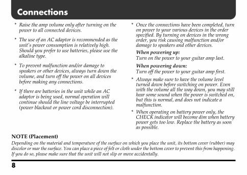
* Raise the amp volume only after turning on thepower to all connected devices.
* The use of an AC adaptor is recommended as the unit’s power consumption is relatively high. Should you prefer to use batteries, please use the alkaline type.
* To prevent malfunction and/or damage to speakers or other devices, always turn down the volume, and turn off the power on all devices before making any connections.
* If there are batteries in the unit while an AC adaptor is being used, normal operation will continue should the line voltage be interrupted (power blackout or power cord disconnection).
* Once the connections have been completed, turn on power to your various devices in the order specified. By turning on devices in the wrong order, you risk causing malfunction and/or damage to speakers and other devices.When powering up:Turn on the power to your guitar amp last.
When powering down:Turn off the power to your guitar amp first.
* Always make sure to have the volume level turned down before switching on power. Even with the volume all the way down, you may still hear some sound when the power is switched on, but this is normal, and does not indicate a malfunction.
* When operating on battery power only, the CHECK indicator will become dim when battery power gets too low. Replace the battery as soon as possible.
NOTE (Placement)Depending on the material and temperature of the surface on which you place the unit, its bottom cover (rubber) may discolor or mar the surface. You can place a piece of felt or cloth under the bottom cover to prevent this from happening. If you do so, please make sure that the unit will not slip or move accidentally.
8
Connections
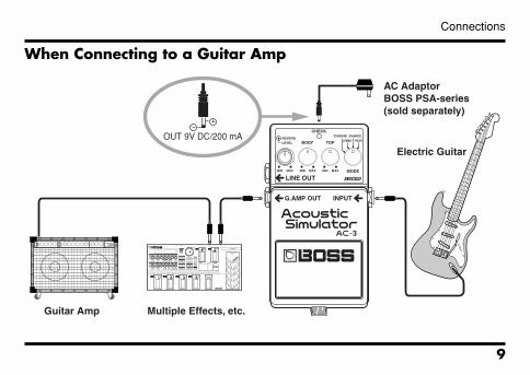
When Connecting to a Guitar Ampfig.09
AC AdaptorBOSS PSA-series(sold separately)
OUT 9V DC/200 mA
Guitar Amp Multiple Effects, etc.
Electric Guitar
9
Connections
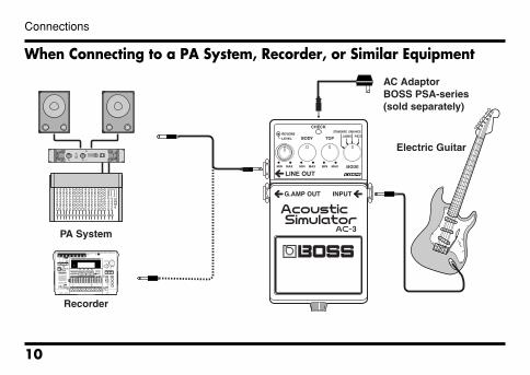
When Connecting to a PA System, Recorder, or Similar Equipmentfig.10
PA System
Recorder
AC AdaptorBOSS PSA-series(sold separately)
Electric Guitar
10
Connections
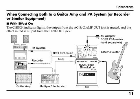
When Connecting Both to a Guitar Amp and PA System (or Recorder or Similar Equipment) With Effect OnThe CHECK indicator lights, the output from the AC-3: G.AMP OUT jack is muted, and the effect sound is output from the LINE OUT jack.fig.11
PA System
Recorder
Guitar Amp Multiple Effects, etc.
Effect sound
Mute
AC AdaptorBOSS PSA-series(sold separately)
Electric Guitar
11
Connections
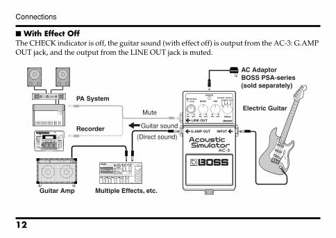
With Effect OffThe CHECK indicator is off, the guitar sound (with effect off) is output from the AC-3: G.AMP OUT jack, and the output from the LINE OUT jack is muted.fig.11_02
PA System
Recorder
Guitar Amp Multiple Effects, etc.
AC AdaptorBOSS PSA-series(sold separately)
Electric Guitar
Guitar sound
(Direct sound)
Mute
12
Connections
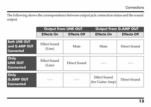
The following shows the correspondence between output jack connection status and the sound output.
Output from LINE OUT Output from G.AMP OUTEffects On Effects Off Effects On Effects Off
Both LINE OUT and G.AMP OUT Connected
Effect Sound (Line)
Mute Mute Direct Sound
Only LINE OUT Connected
Effect Sound (Line)
Direct Sound - - - - - -
Only G.AMP OUT Connected
- - - - - -Effect Sound
(for Guitar Amp)Direct Sound
13
Operating the Unit
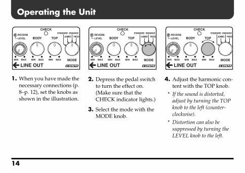
fig.031. When you have made the necessary connections (p. 8–p. 12), set the knobs as shown in the illustration.
fig.04
2. Depress the pedal switch to turn the effect on. (Make sure that the CHECK indicator lights.)
3. Select the mode with the MODE knob.
fig.05
4. Adjust the harmonic con-tent with the TOP knob.
* If the sound is distorted, adjust by turning the TOP knob to the left (counter-clockwise).
* Distortion can also be suppressed by turning the LEVEL knob to the left.
14
Operating the Unit
fig.06
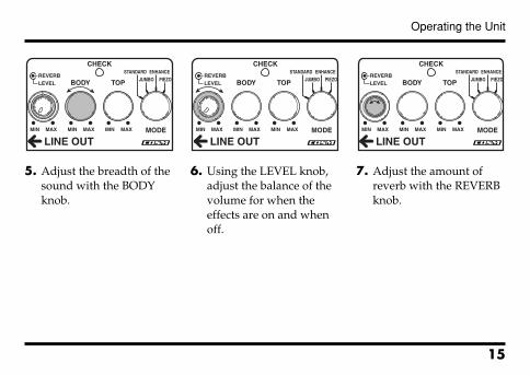
5. Adjust the breadth of the sound with the BODY knob.
fig.07
6. Using the LEVEL knob, adjust the balance of the volume for when the effects are on and when off.
fig.08
7. Adjust the amount of reverb with the REVERB knob.
15
Changing the Battery
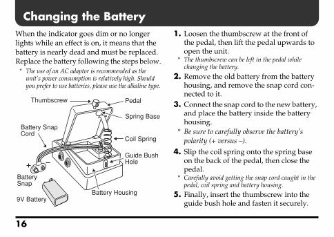
When the indicator goes dim or no longer lights while an effect is on, it means that the battery is nearly dead and must be replaced. Replace the battery following the steps below.* The use of an AC adaptor is recommended as the unit’s power consumption is relatively high. Should you prefer to use batteries, please use the alkaline type.
fig.12
1. Loosen the thumbscrew at the front of the pedal, then lift the pedal upwards to open the unit.
* The thumbscrew can be left in the pedal while changing the battery.
2. Remove the old battery from the battery housing, and remove the snap cord con-nected to it.
3. Connect the snap cord to the new battery, and place the battery inside the battery housing.
* Be sure to carefully observe the battery’s polarity (+ versus –).
4. Slip the coil spring onto the spring base on the back of the pedal, then close the pedal.
* Carefully avoid getting the snap cord caught in the pedal, coil spring and battery housing.
5. Finally, insert the thumbscrew into the guide bush hole and fasten it securely.
Thumbscrew Pedal
Spring Base
Coil Spring
Guide BushHole
Battery Housing
Battery SnapCord
BatterySnap
9V Battery
16
Troubleshooting
Power won’t come on / CHECK indicator doesn’t light: Is the specified adaptor (PSA-series;sold separately) properly connected?Check the connection once more (p. 8).
* Never use any AC adapter other than one specified for use with the AC-3.
Is the battery low or dead?Replace with a new battery (p. 16).
* The battery that was supplied with the unit is for temporary use, intended primarily for testing its operation.
* The use of an AC adaptor is recommended as the unit's power consumption is relatively high. Should you prefer to use batteries, please use the alkaline type.
* To prevent unnecessary battery consumption, be sure to disconnect the plug from the INPUT jack when not using the effects unit (p. 6).
Is your guitar properly connected to the INPUT jack?
Check the connection once more (p. 8).* The power is switched on only when a cable is
plugged in to the INPUT jack.
* The CHECK indicator shows whether the effect is being applied or not. It does not indicate whether the power to the device is on or not.
Sound is distorted: Is the battery low?
As the battery is drained, the CHECK in-dicator dims, and the AC-3 may start to function incorrectly. Replace with a new battery (p. 16).
17
Setting Samples
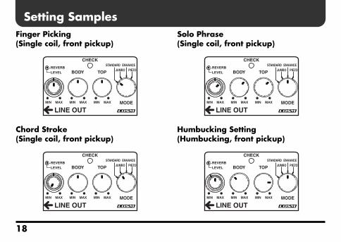
Finger Picking (Single coil, front pickup)fig.13-1Chord Stroke (Single coil, front pickup)fig.13-2
Solo Phrase (Single coil, front pickup)fig.13-3
Humbucking Setting (Humbucking, front pickup)fig.13-4
18
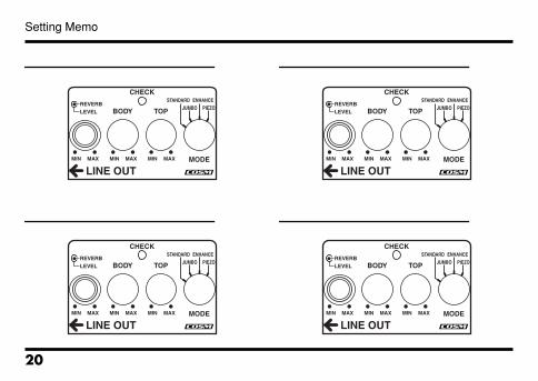
Setting Memo
fig.14
fig.14
fig.14
fig.14
19
Setting Memo
fig.14
fig.14
fig.14
fig.14
20
Specifications
AC-3: Acoustic SimulatorNominal Input Level..................... -20 dBu
Input Impedance............................ 1 MΩ
Nominal Output Level.................. -20 dBu
Output Impedance ........................ 1 kΩ
Recommended Load Impedance ...... 10 kΩ or greater
Controls........................................... Pedal switch, LEVEL knob, REVERB knob, BODY knob,TOP knob, MODE knob
Indicators ........................................ CHECK indicator (Serves also as battery check indicator)
Connectors...................................... INPUT jack, LINE OUT jack, G.AMP OUT jack, AC adaptor jack (DC 9 V)
Power Supply................................. DC 9 V: Dry battery/9 V type (6F22 (carbon), 6LR61 (alkaline)),AC Adaptor (PSA-series: optional)
21
Specifications
Current Draw ................................. 39 mA (DC 9 V)* Expected battery life under continuous use:
Carbon: 3 hours, Alkaline: 10 hoursThese figures will vary depending on the actual conditions of use.
Dimensions..................................... 73 (W) x 129 (D) x 59 (H) mm2-7/8 (W) x 5-1/8 (D) x 2-3/8 (H) inches
Weight ............................................. 440 g /1 lb (including battery)
Accessories...................................... Owner’s Manual, Leaflet (“USING THE UNIT SAFELY,” “IMPORTANT NOTES,” and “Information”),Dry battery/9 V type (6LR61)* The battery that was supplied with the unit is for temporary use-
intended primarily for testing its operation. We also suggest replacing this with an alkaline dry cell.
Option ............................................. AC Adaptor (PSA-series)
* 0 dBu = 0.775 Vrms
* In the interest of product improvement, the specifications and/or appearance of this unit are subject to change without prior notice.
22
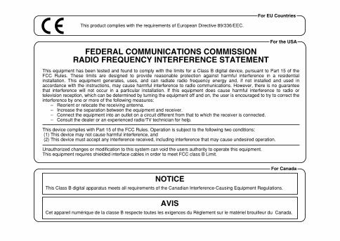
This product complies with the requirements of European Directive 89/336/EEC.
For EU Countries
For Canada
This Class B digital apparatus meets all requirements of the Canadian Interference-Causing Equipment Regulations.
Cet appareil numérique de la classe B respecte toutes les exigences du Règlement sur le matériel brouilleur du Canada.
NOTICE
AVIS
For the USA
FEDERAL COMMUNICATIONS COMMISSIONRADIO FREQUENCY INTERFERENCE STATEMENT
This equipment has been tested and found to comply with the limits for a Class B digital device, pursuant to Part 15 of the FCC Rules. These limits are designed to provide reasonable protection against harmful interference in a residential installation. This equipment generates, uses, and can radiate radio frequency energy and, if not installed and used in accordance with the instructions, may cause harmful interference to radio communications. However, there is no guarantee that interference will not occur in a particular installation. If this equipment does cause harmful interference to radio or television reception, which can be determined by turning the equipment off and on, the user is encouraged to try to correct the interference by one or more of the following measures:
– Reorient or relocate the receiving antenna.– Increase the separation between the equipment and receiver.– Connect the equipment into an outlet on a circuit different from that to which the receiver is connected.– Consult the dealer or an experienced radio/TV technician for help.
This device complies with Part 15 of the FCC Rules. Operation is subject to the following two conditions: (1) This device may not cause harmful interference, and (2) This device must accept any interference received, including interference that may cause undesired operation.
Unauthorized changes or modification to this system can void the users authority to operate this equipment.This equipment requires shielded interface cables in order to meet FCC class B Limit.

G6027114R1