Embed Size (px)
Citation preview
OWNERS MANUAL11006H
REVISION 1/2000
PART NO. 999995
SERIAL NO. __________________________
PO BOX 580697, TULSA, OK 74158-0697
4707 N. MINGO ROAD, TULSA, OK 74117-5904
PHONE (918) 836-0463
SALES FAX (918) 438-6688 SERVICE FAX (918) 834-5979
www.autocrane.com
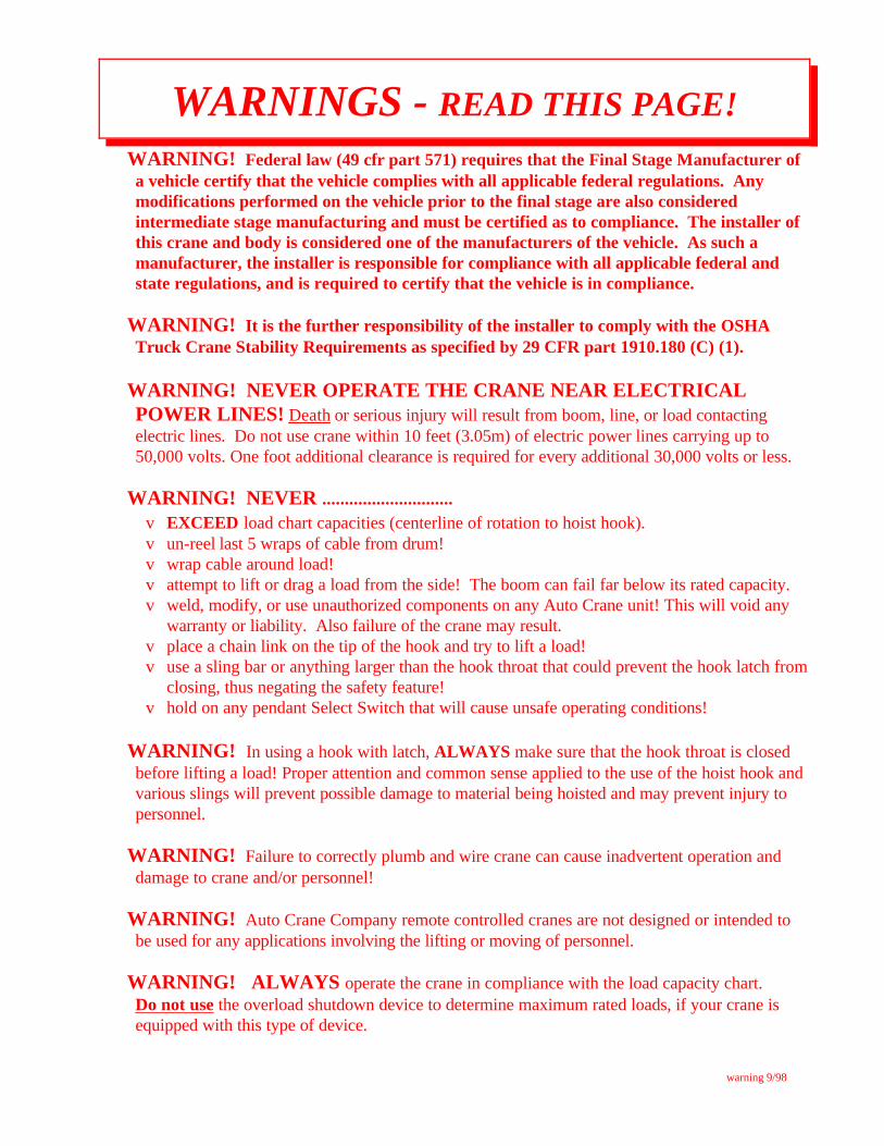
WARNING! Federal law (49 cfr part 571) requires that the Final Stage Manufacturer ofa vehicle certify that the vehicle complies with all applicable federal regulations. Anymodifications performed on the vehicle prior to the final stage are also consideredintermediate stage manufacturing and must be certified as to compliance. The installer ofthis crane and body is considered one of the manufacturers of the vehicle. As such amanufacturer, the installer is responsible for compliance with all applicable federal andstate regulations, and is required to certify that the vehicle is in compliance.
WARNING! It is the further responsibility of the installer to comply with the OSHATruck Crane Stability Requirements as specified by 29 CFR part 1910.180 (C) (1).
WARNING! NEVER OPERATE THE CRANE NEAR ELECTRICALPOWER LINES! Death or serious injury will result from boom, line, or load contactingelectric lines. Do not use crane within 10 feet (3.05m) of electric power lines carrying up to50,000 volts. One foot additional clearance is required for every additional 30,000 volts or less.
WARNING! NEVER .............................v EXCEED load chart capacities (centerline of rotation to hoist hook).v un-reel last 5 wraps of cable from drum!v wrap cable around load!v attempt to lift or drag a load from the side! The boom can fail far below its rated capacity.v weld, modify, or use unauthorized components on any Auto Crane unit! This will void any
warranty or liability. Also failure of the crane may result.v place a chain link on the tip of the hook and try to lift a load!v use a sling bar or anything larger than the hook throat that could prevent the hook latch from
closing, thus negating the safety feature!v hold on any pendant Select Switch that will cause unsafe operating conditions!
WARNING! In using a hook with latch, ALWAYS make sure that the hook throat is closedbefore lifting a load! Proper attention and common sense applied to the use of the hoist hook andvarious slings will prevent possible damage to material being hoisted and may prevent injury topersonnel.
WARNING! Failure to correctly plumb and wire crane can cause inadvertent operation anddamage to crane and/or personnel!
WARNING! Auto Crane Company remote controlled cranes are not designed or intended tobe used for any applications involving the lifting or moving of personnel.
WARNING! ALWAYS operate the crane in compliance with the load capacity chart. Do not use the overload shutdown device to determine maximum rated loads, if your crane isequipped with this type of device.
warning 9/98
WARNINGS - READ THIS PAGE!

LAST PAGEWARRANTY . . . . . . . . . . . . . . . . . . . . . . . . . . . . . . . . . . . . . . . . . . . . . . . . .
9-9.9.9LOAD CHART24 . . . . . . . . . . . . . . . . . . . . . . . . . . . . . . . . . . . . . . . . . . . . . . . .
8-1.0.0TRAVELING BLOCK ASSEMBLY23 . . . . . . . . . . . . . . . . . . . . . . . . . . . . . .
7-1.0.0OUTRIGGERS22 . . . . . . . . . . . . . . . . . . . . . . . . . . . . . . . . . . . . . . . . . . . . . . . .
6-8.0.0RESERVOIRS21 . . . . . . . . . . . . . . . . . . . . . . . . . . . . . . . . . . . . . . . . . . . . . . . .
5-2.0.0ELECTRICAL SECTION20 . . . . . . . . . . . . . . . . . . . . . . . . . . . . . . . . . . . . . . .
4-4.0.0
HOIST ACTUATOR19 . . . . . . . . . . . . . . . . . . . . . . . . . . . . . . . . . . . . . . . . . . .
4-3.0.0AUTOMATIC SAFETY BRAKE18 . . . . . . . . . . . . . . . . . . . . . . . . . . . . . . . . .
4-2.0.0BOOM ASSEMBLY17 . . . . . . . . . . . . . . . . . . . . . . . . . . . . . . . . . . . . . . . . . . .
4-1.0.0PEDESTAL ASSEMBLY16 . . . . . . . . . . . . . . . . . . . . . . . . . . . . . . . . . . . . . . .
3-4.0.0LUBRICATION & MAINTENANCE SCHEDULE15 . . . . . . . . . . . . . . . . . .
3-2.0.0HYDRAULIC VALVES TROUBLESHOOTING14 . . . . . . . . . . . . . . . . . . .
2-9.0.0RELAY KIT13 . . . . . . . . . . . . . . . . . . . . . . . . . . . . . . . . . . . . . . . . . . . . . . . . . .
2-7.0.0OPTIMETER TROUBLESHOOTING12 . . . . . . . . . . . . . . . . . . . . . . . . . . . .
2-6.0.0OVERLOAD SYSTEM / ANTI-2-BLOCK TROUBLESHOOTING11 . . . .
2-3.0.0AMPLIFIER SETUP PROCEDURE10 . . . . . . . . . . . . . . . . . . . . . . . . . . . . . .
2-2.0.0BOOM SUPPORT9 . . . . . . . . . . . . . . . . . . . . . . . . . . . . . . . . . . . . . . . . . . . . .
2-1.0.0MOUNTING & INSTALLATION8 . . . . . . . . . . . . . . . . . . . . . . . . . . . . . . . .
1-4.0.0SAFETY DECALS7 . . . . . . . . . . . . . . . . . . . . . . . . . . . . . . . . . . . . . . . . . . . . .
1-3.2.0INSPECTION, TESTING, & MAINTENANCE6 . . . . . . . . . . . . . . . . . . . . .
1-3.1.0QUALIFICATIONS FOR OPERATORS5 . . . . . . . . . . . . . . . . . . . . . . . . . . .
1-3.0.0OPERATION OF UNIT / OUTRIGGERS 4 . . . . . . . . . . . . . . . . . . . . . . . . .
1-2.0.0OPERATING PRACTICES & WARNINGS3 . . . . . . . . . . . . . . . . . . . . . . . .
1-1.1.0GENERAL SPECIFICATIONS2 . . . . . . . . . . . . . . . . . . . . . . . . . . . . . . . . . .
1-1.0.0INTRODUCTION1 . . . . . . . . . . . . . . . . . . . . . . . . . . . . . . . . . . . . . . . . . . . . .
11006 SERIES - OWNER'S MANUAL
TABLE OF CONTENTS
Auto Crane products are designed to provide manyyears of safe, trouble-free, dependable service whenproperly used and maintained.
To assist you in obtaining the best service fromyour crane and to avoid untimely crane and/or vehiclefailure, this manual provides the following operatingand service instructions. It is specificallyrecommended that all operating and service personnelconsider this manual as mandatory material for readingand study before operating or servicing Auto craneproducts. It is highly recommended that crane owners,equipment managers and supervisors also read thismanual.
Auto Crane has incorporated several safety featuresin the 11006 series cranes for your protection. Thechoice of materials and the design of the electricalsystem minimizes weight and lengthens durability. Thehydraulic components meet or exceed a 3.5:1 safetyfactor. Holding valves prevent the load from droppingif a hose should fail. A 10u filter in the return line ofthe hydraulic system removes dirt and grit that maycause erratic operation. The reservoir has a 15u airfilter in the filler cap. The pump has a 40 meshstrainer in the suction line.
For your convenience the overall dimensions of the11006 series crane are on the General DimensionDrawing. Maximum turning radius at both the hoistmotor and the rotation motor are also on that drawing.
Remember, the crane adds weight to the vehicle.Adding weight may change the driving and ridingcharacteristics of the vehicle unless the appropriateoverload spring(s) are installed on the truck. Thepayload of the vehicle is reduced by the weight of thecrane. The operator should exercise care when loadingthe vehicle. Distributing the payload on the vehicleevenly will greatly improve the driving and ridingcharacteristics of the vehicle. A minimum G.V.W. of30,000 lbs. is recommended for mounting the 11006series cranes.
It has always been Auto Crane Company policy tohandle all warranty claims we receive as promptly aspossible. If a warranty claim involves discrepantmaterial or workmanship, Auto Crane will take
immediate corrective action. It is understandable thatAuto Crane company cannot assume responsibility ofliability when it is obvious that our products have beenabused, mis-used, overloaded or otherwise damaged byinexperienced persons trying to operate the equipmentwithout reading the manual.
Auto Crane will not assume responsibilityor liability for any modifications or changesmade to unit, or installation of componentparts done without authorization.
Auto Crane maintains a strong distributor networkand a knowledgeable Customer Service Department. Inmost cases, an equipment problem is solved via phoneconversation with our customer service department.The customer service department also has the ability tobring a local distributor, a regional sales manager, or afactory serviceman into the solution of an equipmentproblem. If, through no fault of Auto crane company, itis necessary to send an experienced factory servicemanon a field service call, the rates stated in the Auto CraneDistributor's Flat Rate Manual will apply.
Auto Crane Company's extensive Research andDevelopment Program allow our customers to use thebest equipment on the market. Our Engineering Staffand our knowledgeable sales people, are alwaysavailable to our customers in solving crane andwinch-type application problems. When in doubt, callthe Auto Crane factory.
DISTRIBUTOR ASSISTANCE:Should you require any assistance not given in this
manual, we recommend that you consult your nearestAuto Crane Distributor. Our distributors sellauthorized parts and have service departments that cansolve almost any needed repair.
NOTE: THIS MANUALSHOULD REMAIN WITH
THE CRANE AT ALL TIMES.
This manual does not cover all maintenance,operating, or repair instructions pertinent to all possiblesituations. If you require additional information, pleasecontact the Auto Crane Company at the followingtelephone number: (918) 438-2760. The informationcontained in the manual is in effect at the time of thisprinting. Auto Crane Company reserves the right toupdate this material without notice or obligation.
11006int 1/99
INTRODUCTION11006 SERIES
Auto Crane Company issues a limitedwarranty certificate with each unit sold.See last page for warranty policy.
1-1.0.0
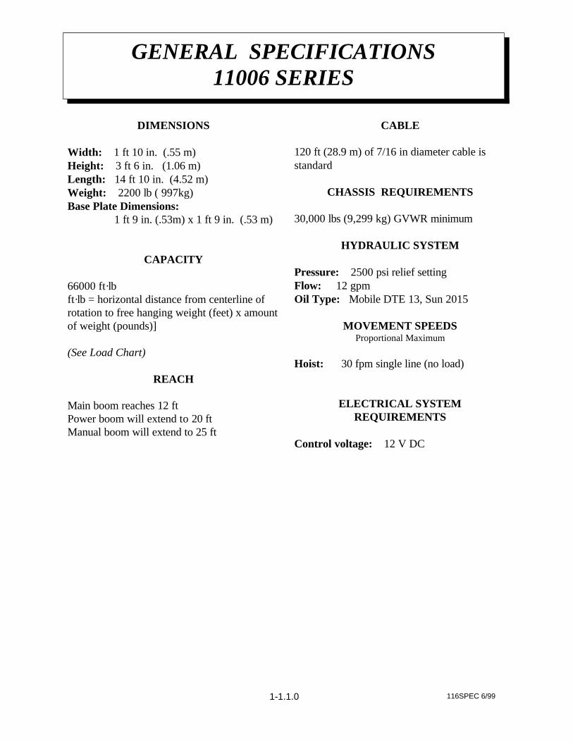
DIMENSIONS
Width: 1 ft 10 in. (.55 m)Height: 3 ft 6 in. (1.06 m)Length: 14 ft 10 in. (4.52 m) Weight: 2200 lb ( 997kg)Base Plate Dimensions: 1 ft 9 in. (.53m) x 1 ft 9 in. (.53 m)
CAPACITY
66000 ft·lbft·lb = horizontal distance from centerline ofrotation to free hanging weight (feet) x amountof weight (pounds)]
(See Load Chart)
REACH
Main boom reaches 12 ftPower boom will extend to 20 ftManual boom will extend to 25 ft
CABLE
120 ft (28.9 m) of 7/16 in diameter cable isstandard
CHASSIS REQUIREMENTS
30,000 lbs (9,299 kg) GVWR minimum
HYDRAULIC SYSTEM
Pressure: 2500 psi relief settingFlow: 12 gpm Oil Type: Mobile DTE 13, Sun 2015
MOVEMENT SPEEDSProportional Maximum
Hoist: 30 fpm single line (no load)
ELECTRICAL SYSTEMREQUIREMENTS
Control voltage: 12 V DC
GENERAL SPECIFICATIONS11006 SERIES
1-1.1.0 116SPEC 6/99
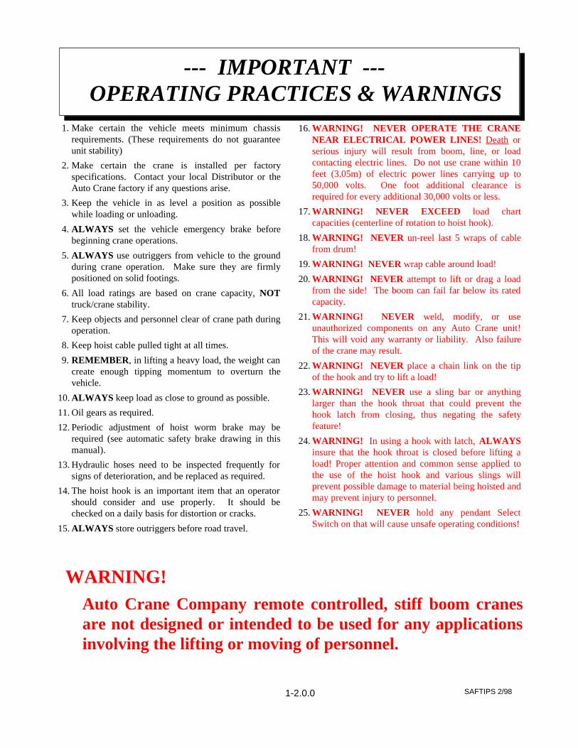
1. Make certain the vehicle meets minimum chassisrequirements. (These requirements do not guaranteeunit stability)
2. Make certain the crane is installed per factoryspecifications. Contact your local Distributor or theAuto Crane factory if any questions arise.
3. Keep the vehicle in as level a position as possiblewhile loading or unloading.
4. ALWAYS set the vehicle emergency brake beforebeginning crane operations.
5. ALWAYS use outriggers from vehicle to the groundduring crane operation. Make sure they are firmlypositioned on solid footings.
6. All load ratings are based on crane capacity, NOTtruck/crane stability.
7. Keep objects and personnel clear of crane path duringoperation.
8. Keep hoist cable pulled tight at all times.
9. REMEMBER, in lifting a heavy load, the weight cancreate enough tipping momentum to overturn thevehicle.
10. ALWAYS keep load as close to ground as possible.
11. Oil gears as required.
12. Periodic adjustment of hoist worm brake may berequired (see automatic safety brake drawing in thismanual).
13. Hydraulic hoses need to be inspected frequently forsigns of deterioration, and be replaced as required.
14. The hoist hook is an important item that an operatorshould consider and use properly. It should bechecked on a daily basis for distortion or cracks.
15. ALWAYS store outriggers before road travel.
16. WARNING! NEVER OPERATE THE CRANENEAR ELECTRICAL POWER LINES! Death orserious injury will result from boom, line, or loadcontacting electric lines. Do not use crane within 10feet (3.05m) of electric power lines carrying up to50,000 volts. One foot additional clearance isrequired for every additional 30,000 volts or less.
17. WARNING! NEVER EXCEED load chartcapacities (centerline of rotation to hoist hook).
18. WARNING! NEVER un-reel last 5 wraps of cablefrom drum!
19. WARNING! NEVER wrap cable around load!
20. WARNING! NEVER attempt to lift or drag a loadfrom the side! The boom can fail far below its ratedcapacity.
21. WARNING! NEVER weld, modify, or useunauthorized components on any Auto Crane unit!This will void any warranty or liability. Also failureof the crane may result.
22. WARNING! NEVER place a chain link on the tipof the hook and try to lift a load!
23. WARNING! NEVER use a sling bar or anythinglarger than the hook throat that could prevent thehook latch from closing, thus negating the safetyfeature!
24. WARNING! In using a hook with latch, ALWAYSinsure that the hook throat is closed before lifting aload! Proper attention and common sense applied tothe use of the hoist hook and various slings willprevent possible damage to material being hoisted andmay prevent injury to personnel.
25. WARNING! NEVER hold any pendant SelectSwitch on that will cause unsafe operating conditions!
--- IMPORTANT --- OPERATING PRACTICES & WARNINGS
WARNING!Auto Crane Company remote controlled, stiff boom cranesare not designed or intended to be used for any applicationsinvolving the lifting or moving of personnel.
1-2.0.0 SAFTIPS 2/98
26. Make sure this manual has been thoroughly read byall crane operating personnel and supervisors.
27. A routine inspection of the crane should be mandatorybefore each operating day. Any defects should becorrected immediately.
28. At a job site the vehicle should be positioned so thatthe crane can adequately reach the load within therated capacity (centerline of rotation to hoist hook).
29. Keep the vehicle as level as possible during operation.
30. For electric cranes, engage emergency brake andleave ignition on with transmission in neutral (or inpark for automatic transmissions). Activate any cranepower switches. For Auto Crane units requiringbattery and hydraulic operation, engage emergencybrake, place gear selector in neutral, press clutch,activate PTO, release clutch and after hydraulic fluidis warm, set throttle control to proper engine speed.
31. Always use outriggers from the truck to the ground.Be sure these are firm and adequately positioned.When rotating, keep load as low to the ground aspossible.
32. Remove pendant control from cab or storage area. Onsmaller units, plug pendant into receptacle on crane.On larger units, remove pendant control from guardand unwrap cable from boom. Do not operate craneuntil cable is unwound completely. On all cranes,detach hook from dead man. Crane is now ready foroperation.
33. Always boom up before rotating so the boom willclear the required boom support.
34. When extending the boom, always maintain clearancebetween the boom crown and the traveling block orhoist hook.
35. Always observe safe and practical operation to avoidpossible accidents. Refer to Safety Tips andPrecautions.
36. After completing lifting operations, return the boomto stowed position on the boom support. Avoidunneeded pressure on the boom support.
37. Store pendant control on proper location (in cab or oncrane).
38. Return outriggers to stowed position. Make sure theyare pinned in place or jacklegs are returned tocompartment.
39. Check work area for any tools or equipment notstored.
40. Release throttle control, depress clutch and disengagePTO. Deactivate any crane power switches.
41. Report any unusual occurrence during crane operationthat may indicate required maintenance or repair.
42. NEVER use two cranes to support a load too large foreither crane.
43. Spray all electrical equipment with special corrosionresistant coating. This eliminates rust or corrosiondue to melting and freezing action of condensation.
1-3.0.0 116OPER 1/99
--- IMPORTANT --- OPERATION OF UNIT
OPERATION OF OUTRIGGERS
For hydraulic outriggers:1. Shift crane/outrigger control valve to
"outrigger" position.2. After outriggers are positioned, return
crane/outrigger selector to "crane" position.3. Crane is now ready to operate.
OPERATORS
1 Crane operation shall be limited to personnel withthe following minimum qualifications:
A. designated persons
B. trainees under the direct supervision of a designatedperson
C. maintenance and test personnel (when it isnecessary in the performance of their duties)
D. inspectors (crane).
2 No one other than the personnel specified above shallenter the operating area of a crane with the exceptionof persons such as oilers, supervisors, and thosespecified persons authorized by supervisors whoseduties require them to do so and then only in theperformance of their duties and with the knowledgeof the operator or other persons.
QUALIFICATIONS FOR OPERATORS
3 Operators shall be required by the employer to pass apractical operating examination. Qualifications shallbe limited to the specific type of equipment for whichexamined.
4 Operators and operator trainees shall meet thefollowing physical qualifications:
A. Vision of at least 20/30 Snellen in one eye and20/50 in the other, with or without corrective lenses.
B. Ability to distinguish colors, regardless of position,if colors differentiation is required for operation.
C. Adequate hearing with or without hearing aid forthe specific operation.
5 Evidence of physical defects or emotional instabilitywhich render a hazard to operator or others, whichin the opinion of the examiner could interfere withthe operator's performance may be sufficient causefor disqualification. In such cases, specialized clinicalor medical judgment and tests may be required.
6 Evidence that the operator is subject to seizures orloss of physical control shall be sufficient reason fordisqualification. Specialized medical tests may berequired to determine these conditions.
7 Operators and operator trainees should have normaldepth perception, coordination, and no tendencies todizziness or similar undesirable characteristics.
8 In addition to the above listed requirements, theoperator shall:
A. Demonstrate the ability to comprehend and interpretall labels, operator's manuals, safety codes and otherinformation pertinent to correct crane operations.
B. Possess knowledge of emergency procedures andimplementation of same.
C. Demonstrate to the employer the ability to operatethe specific type of equipment.
D. Be familiar with the applicable safety regulations.
E. Understand responsibility for maintenancerequirements of crane.
F. Be thoroughly familiar with the crane and itscontrol functions.
G. Understand the operating procedures as outlined bythe manufacturer.
CONDUCT OF OPERATORS
9 The operator shall not engage in any practice whichwill divert his attention while actually operating thecrane.
10 Each operator shall be responsible for thoseoperations under the operator's direct control.Whenever there is any doubt as to safety, theoperator shall consult with the supervisor beforehandling the loads.
11 The operator should not leave a suspended loadunattended unless specific precautions have beeninstituted and are in place.
12 If there is a warning sign on the switch or enginestarting controls, the operator shall not close theswitch or start the engine until the warning sign hasbeen removed by the appointed person.
13 Before closing the switch or starting the engine, theoperator shall see that all controls are in the "OFF"or neutral position and all personnel are in the clear.
14 If power fails during operation, the operator shall:
A. move power controls to the "OFF" or neutralposition.
QUALIFICATIONS FOR AND CONDUCT OF OPERATORS AND
OPERATING PRACTICES
QUAL 7/981-3.1.0
B. land the suspended load and boom, if practical.
15 The operator shall be familiar with the equipmentand its proper care. If adjustments or repairs arenecessary, the operator shall report the samepromptly to the appointed person, and shall alsonotify the next operator.
16 All controls shall be tested by the operator at thestart of each shift. If any controls do not operateproperly, they shall be adjusted or repaired beforeoperations are begun.
17 Stabilizers shall be visible to the operator whileextending or setting unless operator is assisted by asignal person.
OPERATING PRACTICES
HANDLING THE LOAD
18 Size of load
A. No crane shall be loaded beyond the rated loadexcept for test purposes.
B. The load to be lifted is to be within the rated load ofthe crane and its existing configuration.
C. When loads which are not accurately known are tobe lifted, the person responsible for the job shallascertain that the weight of the load does not exceedthe crane rated load at the radius at which the loadis to be lifted.
19 Attaching the load
A. The load shall be attached to the hook by means ofslings or other devices of sufficient capacity.
B. Hoist rope shall not be wrapped around the load.
20 Moving the load
A. The operator shall determine that:
B. The crane is level and, where necessary, thevehicle/carrier is blocked properly.
C. The load is well secured and balanced in the sling orlifting device before it is lifted more than a fewinches.
D. Means are provided to hold the vehicle stationarywhile operating the crane.
E. Before starting to lift, the hook shall brought overthe load in such a manner as to minimize swinging.
F. During lifting care shall be taken that:
1. there is no sudden acceleration ordeceleration of the moving load.
2. load, boom or other parts of the crane donot contact any obstruction.
G. Cranes shall not be used for dragging loadssideways.
H. This standard recognizes that articulating boomcranes are designed and intended for handlingmaterials. They do not meet personnel lift orelevator requirements. Therefore, no lifting,lowering, swinging or traveling shall be done whilea person is on the hook or load. Hook attachedsuspended work platforms (baskets) shall not beused with cranes covered by this standard. Workplatforms attached to the boom must be approved bycrane manufacturer.
I. The operator should avoid carrying loads overpeople.
J. When the crane is so equipped, the stabilizers shallbe fully extended and set. Blocking under stabilizersshall meet the requirements as follows:
1. strong enough to prevent crushing.
2. of such thickness, width and length as tocompletely support the stabilizer pad.
K. Firm footing under all tires, or individual stabilizerpads should be level. Where such a footing is nototherwise supplied, it should be provided bytimbers, cribbing, or other structural members todistribute the load so as to not exceed allowablebearing capacity or the underlying material.
L. In transit, the boom shall be carried in stowedposition.
M. When rotating the crane, sudden starts and stopsshall be avoided. rotational speed shall be such thatthe load does not swing out beyond the radius atwhich it can be controlled.
N. The crane shall not be transported with a load onthe hook unless recommended by the manufacturer.
O. No person should be permitted to stand or passunder a suspended load.
21 Stowing procedure. Follow the manufacturer'sprocedure and sequence when stowing andun-stowing the crane.
QUALIFICATIONS FOR AND CONDUCT OF OPERATORS AND
OPERATING PRACTICES
QUAL 7/981-3.1.1
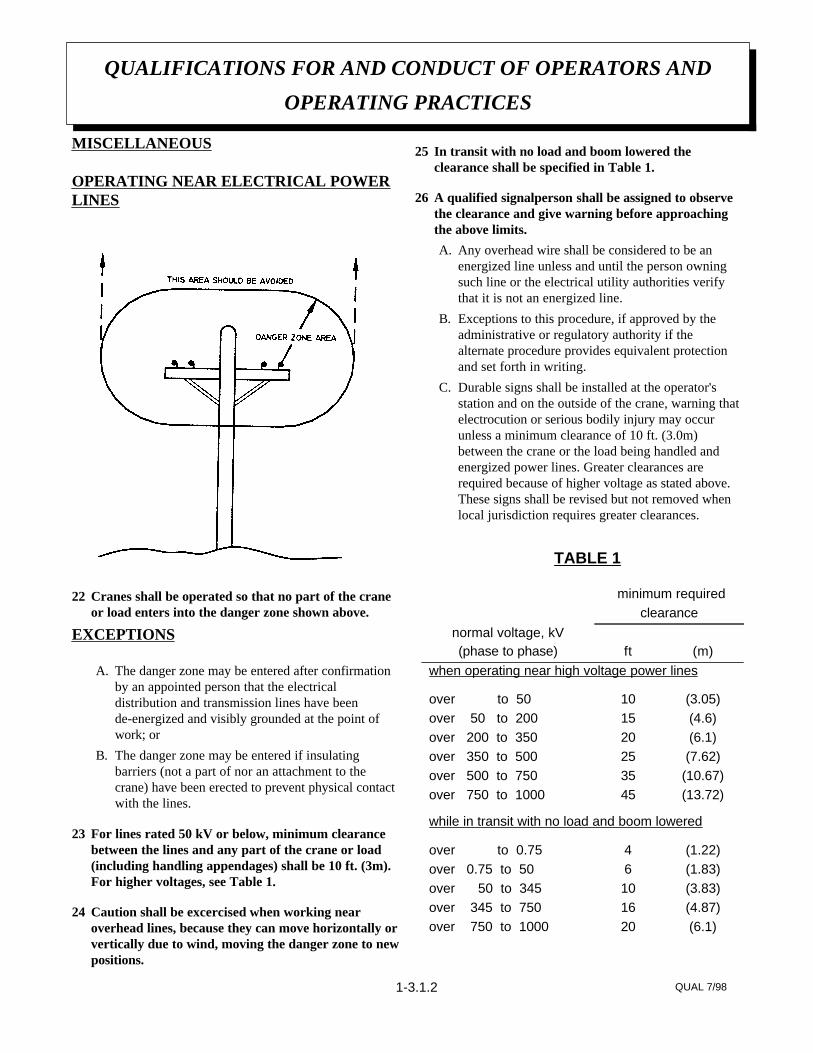
MISCELLANEOUS
OPERATING NEAR ELECTRICAL POWERLINES
22 Cranes shall be operated so that no part of the craneor load enters into the danger zone shown above.
EXCEPTIONS
A. The danger zone may be entered after confirmationby an appointed person that the electricaldistribution and transmission lines have beende-energized and visibly grounded at the point ofwork; or
B. The danger zone may be entered if insulatingbarriers (not a part of nor an attachment to thecrane) have been erected to prevent physical contactwith the lines.
23 For lines rated 50 kV or below, minimum clearancebetween the lines and any part of the crane or load(including handling appendages) shall be 10 ft. (3m).For higher voltages, see Table 1.
24 Caution shall be excercised when working nearoverhead lines, because they can move horizontally orvertically due to wind, moving the danger zone to newpositions.
25 In transit with no load and boom lowered theclearance shall be specified in Table 1.
26 A qualified signalperson shall be assigned to observethe clearance and give warning before approachingthe above limits.
A. Any overhead wire shall be considered to be anenergized line unless and until the person owningsuch line or the electrical utility authorities verifythat it is not an energized line.
B. Exceptions to this procedure, if approved by theadministrative or regulatory authority if thealternate procedure provides equivalent protectionand set forth in writing.
C. Durable signs shall be installed at the operator'sstation and on the outside of the crane, warning thatelectrocution or serious bodily injury may occurunless a minimum clearance of 10 ft. (3.0m)between the crane or the load being handled andenergized power lines. Greater clearances arerequired because of higher voltage as stated above.These signs shall be revised but not removed whenlocal jurisdiction requires greater clearances.
QUALIFICATIONS FOR AND CONDUCT OF OPERATORS AND
OPERATING PRACTICES
QUAL 7/981-3.1.2
(6.1)20over 750 to 1000(4.87)16over 345 to 750(3.83)10over 50 to 345(1.83)6over 0.75 to 50(1.22)4over to 0.75
while in transit with no load and boom lowered
(13.72)45over 750 to 1000(10.67)35over 500 to 750(7.62)25over 350 to 500(6.1)20over 200 to 350(4.6)15over 50 to 200(3.05)10over to 50
when operating near high voltage power lines
(m)ft(phase to phase)normal voltage, kV
clearance minimum required
TABLE 1
INSPECTION CLASSIFICATION
27 Initial inspection. Prior to initial use, all new, altered,modified or extensively repaired cranes shall beinspected by a designated person to insure compli-ance with provisions of this standard.
28 Regular inspection. Inspection procedure for cranesin regular service is divided into two general classifi-cations based upon the intervals at which inspectionshould be performed. The intervals in turn aredependent upon the nature of the components of thecrane and the degree of their exposure to wear,deterioration, or malfunction. The two general classi-fications are herein designated as "frequent" and"periodic" with respective intervals between inspec-tions as defined below.
A. frequent inspection - daily to monthly intervals
B. periodic inspection - one to twelve intervals, or asspecifically recommended by the manufacturer
FREQUENT INSPECTION
29 Inspection shall be performed by designatedpersonnel.
A. control mechanisms for maladjustment interferingwith proper operation - daily, when used
B. control mechanisms for excessive wear of compo-nents and contamination by lubricants or otherforeign matter
C. safety devices for malfunction
D. all hydraulic hoses, particularly those which flex innormal operation of crane functions, should bevisually inspected once every working day, whenused
E. hooks and latches for deformation, chemicaldamage, cracks, and wear. Refer to ANSI/ASMEB30.10
F. rope reeving for compliance with crane manufac-turer's specifications, if optional winch is used
G. electrical apparatus for malfunctioning, signs ofexcessive deterioration, dirt and moisture accumula-tion
H. hydraulic system for proper oil level and leaks daily
I. tires for recommended inflation pressure, cuts andloose wheel nuts
J. connecting pins and locking device for wear anddamage
PERIODIC INSPECTION
30 Deformed, cracked or corroded members in thecrane structure and carrier.
31 Loose bolts, particularly mounting bolts.
32 Cracked or worn sheaves and drums.
33 Worn, cracked, or distorted parts such as pins,bearings, shafts, gears, rollers and devices.
34 Excessive wear on brake and clutch system parts andlining.
35 Crane hooks inspected for cracks.
36 Travel steering, braking, and locking devices, formalfunction.
37 Excessively worn or damaged tires.
38 Hydraulic and pneumatic hose, fittings, and tubinginspection.
A. evidence of leakage at the surface of the flexiblehose or its junction with metal and coupling
B. blistering, or abnormal deformation to the outercovering of the hydraulic or pneumatic hose
C. leakage at threaded or clamped joints that cannot beeliminated by normal tightening or recommendedprocedures
D. evidence or excessive abrasion or scrubbing on theouter surface of a hose, rigid tube, or fitting. Meansshall be taken to eliminate the interference of
INSPECTION, TESTING AND MAINTENANCE
GENERAL
INSP 9/981-3.2.0
elements in contact or otherwise protect thecomponents
39 Hydraulic and pneumatic pumps and motorsinspection.
A. loose bolts or fasteners
B. leaks at joints between sections
C. shaft seal leaks
D. unusual noises or vibrations
E. loss of operating speed
F. excessive heating of the fluid
G. loss of pressure
40 Hydraulic and pneumatic valves inspection.
A. cracks in valve housing
B. improper return of spool to neutral position
C. leaks at spools or joints
D. sticking spools
E. failure of relief valves to attain or maintain correctpressure setting
F. relief valve pressure shall be checked as specified bythe manufacturers
41 Hydraulic and pneumatic cylinders inspection.
A. drifting caused by fluid leaking across piston
B. rod seals leaking
C. leaks at welding joints
D. scored, nicked, or dented cylinder rods
E. damaged case (barrel)
F. loose or deformed rod eyes or connecting joints
42 Hydraulic filters. Evidence of rubber particles on thefilter elements may indicate hose, "O" ring, or otherrubber component deterioration. Metal chips orpieces on the filter may denote failure in pumps,motors, or cylinders. Further checking will be
necessary to determine origin of the problem beforecorrective action can be taken.
43 Labels are to be in place and legible.
CRANES NOT IN REGULAR USE
44 A crane which has been idle for a period of over onemonth or more, but not less than six months, shall begiven an inspection conforming with the initial-regular- frequent inspections.
45 A crane which has been idle for a period of over sixmonths shall be given a complete inspection conform-ing with the initial-regular-frequent inspectionrequirements.
INSPECTION RECORDS
46 Dated records for periodic inspection should be madeon critical items such as brakes, crane hooks, rope,hydraulic and pneumatic cylinders, and hydraulicand pneumatic relief pressure valves. Records shouldbe kept available to an appointed person.
OPERATIONAL TESTS
47 Prior to initial use, all new, altered, modified, orextensively repaired cranes shall be tested for compli-ance with the operational requirements of thissection, including functions such as the following:
A. load lifting and lowering mechanisms
B. boom lifting and lowering mechanisms
C. boom extension and retraction mechanisms
D. swing mechanisms
E. safety devices
F. operating controls comply with appropriate functionlabels
Operational crane test results shall be madeavailable to an appointed person.
RATED TEST LOADPrior to initial use, altered, modified, orextensively repaired cranes shall be load
INSPECTION, TESTING AND MAINTENANCE
GENERAL
INSP 9/981-3.2.1
tested by or under the direction of anappointed person.
48 Test loads shall not exceed 110% of the manufac-turer's load ratings.
49 Written reports shall be maintained showing testprocedures and confirming the adequacy of repairs.
MAINTENANCE
PREVENTIVE MAINTENANCE
50 Before adjustment and repairs are started on a crane,the following precautions shall be taken asapplicable:
A. crane placed where it will cause the least interfer-ence with other equipment or operations
B. all controls at the "off" position
C. starting means rendered inoperative
D. boom lowered to the ground if possible or otherwisesecured against dropping
E. relieve hydraulic oil pressure from all hydrauliccircuits before loosening or removing hydrauliccomponents
51 Warning or "OUT OF ORDER" signs shall be placedon the crane controls.
52 After adjustments and repairs have been made, thecrane shall not be returned to service until all guardshave been reinstalled, trapped air removed fromhydraulic system (if required), safety devices reacti-vated, and maintenance equipment removed.
ADJUSTMENTS AND REPAIRS
53 Any hazardous conditions disclosed by the inspectionrequirements shall be corrected before operation ofcrane is resumed, Adjustments and repairs shall bedone only by designated personnel.
54 Adjustments shall be maintained to assure correctfunctioning of components, The following areexamples:
A. functional operating mechanism
B. safety devices
C. control systems
55 Repairs or replacements shall be provided as neededfor operation.
The following are examples:
A. critical parts of functional operating mechanismswhich are cracked, broken, corroded, bent, or exces-sively worn
B. critical parts of the crane structure which arecracked, bent, broken, or excessively corroded
C. crane hooks showing cracks, damage, or corrosionshall be taken out of service. Repairs by welding arenot recommended
56 Instructions shall be provided by the manufacturerfor the removal of air from hydraulic circuits.
LUBRICATIONAll moving parts of the crane, for whichlubrication is specified, should be regularlylubricated per the manufacturer'srecommendations and procedures.
ROPE INSPECTION
57 Frequent Inspection
A. All running ropes in service should be visuallyinspected once each working day. A visual inspec-tion shall consist of observation of all rope whichcan be in use during the days operations. Thesevisual observations should be considered withdiscovering gross damage such as listed below,which may be an immediate hazard.
1. distortion of the rope such as kinking,crushing, un-stranding, birdcaging, mainstrand displacement, or core protrusion.Loss of rope diameter in a short length orunevenness of outer strands should bereplaced
2. general corrosion
INSPECTION, TESTING AND MAINTENANCE
GENERAL
INSP 9/981-3.2.2
3. broken or cut strands;
4. number, distribution and type of visiblebroken wires. When such damage isdiscovered, the rope shall either beremoved from service or given asinspection.
B. Care shall be taken when inspecting sections ofrapid deterioration such as flange points, crossoverpoints, and repetitive pickup points on drums.
58 Periodic inspection
A. The inspection frequency shall be determined by aqualified person and shall be based on such factorsas:
1. expected rope life as determined byexperience on the particular installation orsimilar installations
2. severity of environment
3. percentage of capacity lifts
4. frequency rates of operation
5. exposure to shock loads
Inspection need not be at equal calendarintervals and should be more frequent as therope approaches the end of it's service life.This inspection shall be made at leastannually.
B. Periodic inspection shall be performed by a desig-nated person. This inspection shall cover the entirelength of the rope. Only the surface wires need beinspected. No attempt should be made to open therope. Any deterioration results in appreciable loss oforiginal strength, such as described below, shall benoted and determination made as to whether use ofthe rope would constitute a hazard: points listedabove reduction of rope diameter below nominaldiameter due to loss of core support, internal orexternal corrosion, or wear of outside wires;severely corroded, cracked, bent, worn or improp-erly applied connections;
C. Care shall be taken when inspecting sections subjectto rapid deterioration such as the following:
1. sections in contact with saddles, equalizersheaves, or other sheaves where rope travelis limited
2. sections of the rope at or near terminal endswhere corroded or broken wires mayprotrude
ROPE REPLACEMENT
59 No precise rules can be given for determination of theexact time for replacement of rope, since manyvariable factors are involved.
Continued use in this respect depends upongood judgement by a designated person inevaluating remaining strength in a used ropeafter allowance for deterioration disclosed byinspection. Continued rope operation dependsupon this remaining strength.
60 Conditions such as the following shall be reason forquestioning continued use of the rope or increasingthe frequency of inspection:
A. in running ropes, six randomly distributed brokenwires in one lay or three broken wires in one strandin one lay
B. one outer wire broken at the contact point with thecore of the rope structure and protrudes or loops outof the rope structure. Additional inspection of thissection is required
C. wear of one third of the original diameter of theoutside individual wire
D. kinking, crushing, birdcaging, or any other damageresulting in distortion of the rope structure
E. evidence of any heat damage from any cause
F. reduction from nominal diameter of more than 1/64in. (0.4mm) for diameters up to and including 5/16in. (8 mm), 1/32 in. (0.8 mm) for diameter 3/8 in.(9.5 mm) to and including 1/2 in. (13 mm), 3/64 in.(1.2 mm) for diameter 9/16 in. (14.5 mm) to andincluding 3/4 in. (19 mm). 1/16 in. (1.6 mm) fordiameter 7/8 in. (22 mm) to and including 11/8 in.(29 mm), 3/32 in. (2.4 mm) for diameters 11/4 in.(32 mm) to and including 11/2 in. (38 mm)
INSPECTION, TESTING AND MAINTENANCE
GENERAL
INSP 9/981-3.2.3
G. In standing ropes, more than two broken wires inone lay in sections beyond end connections or morethan one broken wire at an end connection.
H. Replacement rope shall have a strength rating atleast as great as the original rope furnished orrecommended by the crane manufacturer. Anydeviation from the original size, grade, or construc-tion shall be specified by a rope manufacturer, or aqualified person.
61 Rope not in regular use: all rope which has been idlefor a period of a month or more due to shutdown orstorage of a crane on which it is installed, shall begiven and inspection in accordance with above infor-mation before it is placed in service. This inspectionshall be for all types of deterioration and shall beperformed by a qualified person.
62 Inspection records
A. frequent inspection- no records required
B. periodic inspections- in order to establish data as abasis for judging the proper time for replacement, adated report condition at each periodic inspectionshould be kept on file. This report shall cover points of deterioration listed above.
ROPE MAINTENANCE
63 Rope should be stored to prevent damage ordeterioration.
64 Unreeling or uncoiling of rope shall be done asrecommended by the rope manufacturer and withcare to avoid kinking or inducing twist.
65 Before cutting a rope, seizing shall be placed on eachside of the place where the rope is to be cut to preventunlaying of the strands. On pre-formed rope, oneseizing on each side of the cut is required. Onnon-preformed ropes of 7/8 in. (22 mm) diameter orsmaller, two seizings on each side of the cut arerequired, and for non-preformed rope 1 in. (25 mm)diameter or larger, three seizings on each side of thecut are required.
66 During installation care should be exercised to avoiddragging of the rope in the dirt or around objectswhich will scrape, nick crush or induce sharp bendsin it.
67 Rope should be maintained in a well-lubricatedcondition. It is important that lubricant applied as apart of a maintenance program shall be compatiblewith the original lubricant and to this end the ropemanufacturer should be consulted. Lubricant appliedshall be the type which does not hinder visual inspec-tion. Those sections of rope which are located oversheaves or otherwise hidden during inspection andmaintenance procedures require special attentionwhen lubricating rope. The object of rope lubricationis to reduce internal friction and to prevent corrosion.
68 When an operating rope shows greater wear or welldefined localized areas than on the remainder of therope, rope life can be extended in cases where asection at the worn end, and thus shifting the wear todifferent areas of the rope.
INSPECTION, TESTING AND MAINTENANCE
GENERAL
INSP 9/981-3.2.4
SAFETY DECAL SECTION
116DEC 5/99
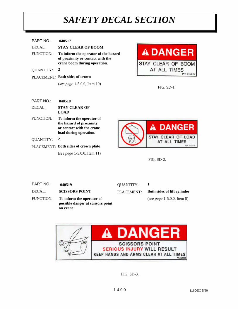
(see page 1-5.0.0, Item 10)
Both sides of crownPLACEMENT:
2QUANTITY:
To inform the operator of the hazardof proximity or contact with thecrane boom during operation.
FUNCTION:
STAY CLEAR OF BOOMDECAL:
040517PART NO.:
(see page 1-5.0.0, Item 11)
Both sides of crown platePLACEMENT:
2QUANTITY:
To inform the operator ofthe hazard of proximityor contact with the craneload during operation.
FUNCTION:
STAY CLEAR OFLOAD
DECAL:
040518PART NO.:
FIG. SD-1.
(see page 1-5.0.0, Item 8)To inform the operator ofpossible danger at scissors pointon crane.
FUNCTION:
Both sides of lift cylinderPLACEMENT:SCISSORS POINTDECAL:
1QUANTITY: 040519PART NO.:
FIG. SD-3.
FIG. SD-2.
1-4.0.0
SAFETY DECAL SECTION
116DEC 5/99
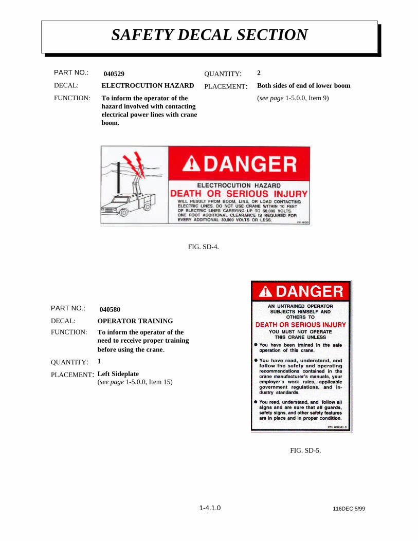
Left Sideplate(see page 1-5.0.0, Item 15)
PLACEMENT:
1QUANTITY:
To inform the operator of theneed to receive proper trainingbefore using the crane.
FUNCTION:
OPERATOR TRAININGDECAL:
040580PART NO.:
FIG. SD-5.
FIG. SD-4.
1-4.1.0
(see page 1-5.0.0, Item 9)To inform the operator of thehazard involved with contactingelectrical power lines with craneboom.
FUNCTION:
Both sides of end of lower boomPLACEMENT:ELECTROCUTION HAZARDDECAL:
2QUANTITY: 040529PART NO.:
SAFETY DECAL SECTION
116DEC 5/99
FIG. SD-7.
FIG. SD-8.
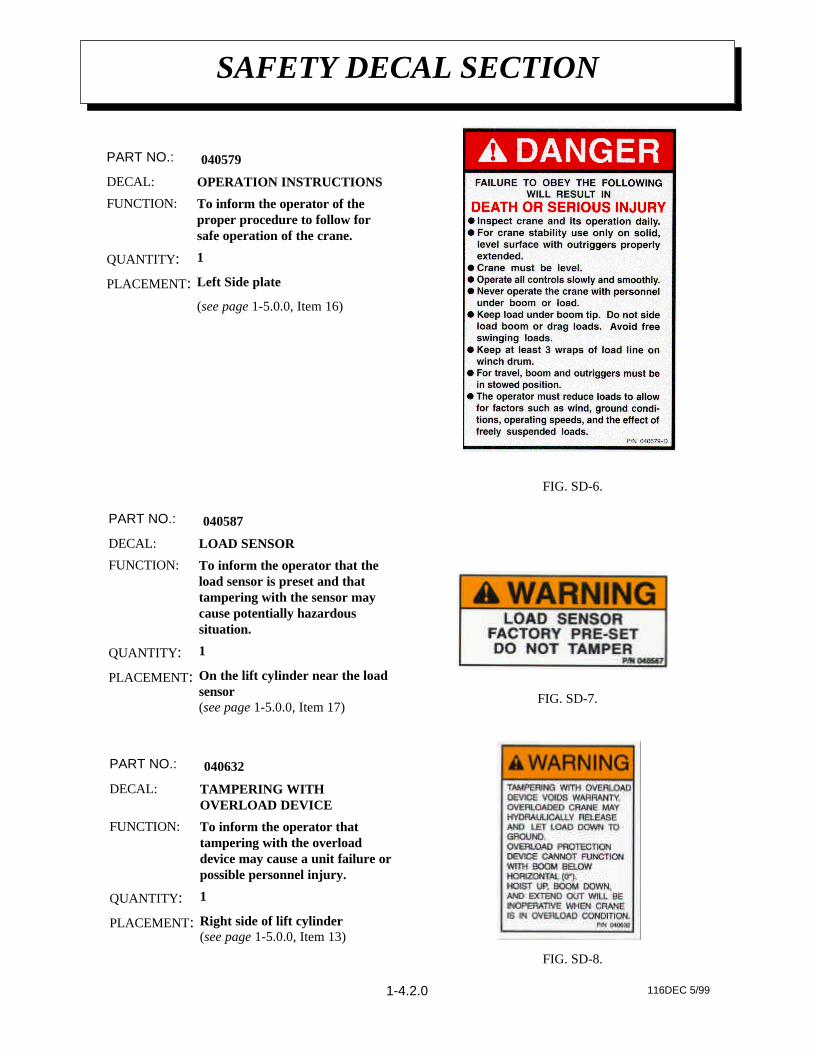
Right side of lift cylinder(see page 1-5.0.0, Item 13)
PLACEMENT:
1QUANTITY:
To inform the operator thattampering with the overloaddevice may cause a unit failure orpossible personnel injury.
FUNCTION:
TAMPERING WITHOVERLOAD DEVICE
DECAL:
040632PART NO.:
(see page 1-5.0.0, Item 16)
Left Side platePLACEMENT:
1QUANTITY:
To inform the operator of theproper procedure to follow forsafe operation of the crane.
FUNCTION:
OPERATION INSTRUCTIONSDECAL:
040579PART NO.:
FIG. SD-6.
On the lift cylinder near the loadsensor(see page 1-5.0.0, Item 17)
PLACEMENT:
1QUANTITY:
To inform the operator that theload sensor is preset and thattampering with the sensor maycause potentially hazardoussituation.
FUNCTION:
LOAD SENSORDECAL:
040587PART NO.:
1-4.2.0
SAFETY DECAL SECTION
116DEC 5/99
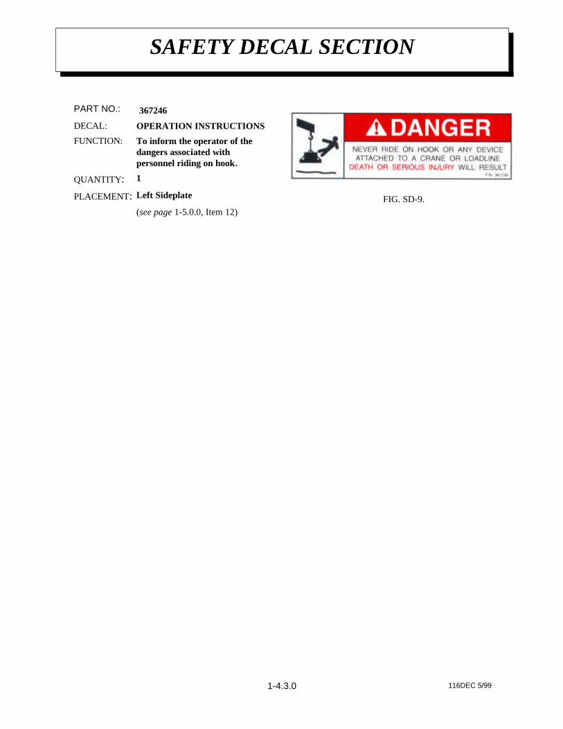
(see page 1-5.0.0, Item 12)
Left SideplatePLACEMENT:
1QUANTITY:
To inform the operator of thedangers associated withpersonnel riding on hook.
FUNCTION:
OPERATION INSTRUCTIONSDECAL:
367246PART NO.:
FIG. SD-9.
1-4.3.0
AW466210 5/99
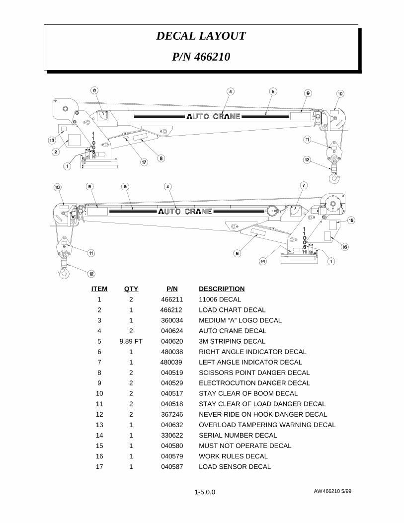
DECAL LAYOUT
P/N 466210
LOAD SENSOR DECAL040587117
WORK RULES DECAL040579116
MUST NOT OPERATE DECAL040580115
SERIAL NUMBER DECAL330622114
OVERLOAD TAMPERING WARNING DECAL040632113
NEVER RIDE ON HOOK DANGER DECAL367246212
STAY CLEAR OF LOAD DANGER DECAL040518211
STAY CLEAR OF BOOM DECAL040517210
ELECTROCUTION DANGER DECAL04052929
SCISSORS POINT DANGER DECAL04051928
LEFT ANGLE INDICATOR DECAL480039 17
RIGHT ANGLE INDICATOR DECAL48003816
3M STRIPING DECAL0406209.89 FT5
AUTO CRANE DECAL04062424
MEDIUM “A” LOGO DECAL36003413
LOAD CHART DECAL466212 12
11006 DECAL46621121
DESCRIPTIONP/NQTYITEM
1-5.0.0
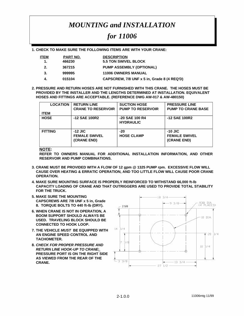
1. CHECK TO MAKE SURE THE FOLLOWING ITEMS ARE WITH YOUR CRANE:
ITEM PART NO. DESCRIPTION1. 466230 5.5 TON SWIVEL BLOCK
2. 367215 PUMP ASSEMBLY (OPTIONAL)
3. 999995 11006 OWNERS MANUAL
4. 015104 CAPSCREW, 7/8 UNF x 5 in, Grade 8 (4 REQ'D)
2. PRESSURE AND RETURN HOSES ARE NOT FURNISHED WITH THIS CRANE. THE HOSES MUST BEPROVIDED BY THE INSTALLER AND THE LENGTHS DETERMINED AT INSTALLATION. EQUIVALENTHOSES AND FITTINGS ARE ACCEPTABLE. (REFERENCE DWG AW-017 & AW-480150)
-10 JICFEMALE SWIVEL(CRANE END)
-20 HOSE CLAMP
-12 JIC FEMALE SWIVEL(CRANE END)
FITTING
-12 SAE 100R2-20 SAE 100 R4HYDRAULIC
-12 SAE 100R2HOSE
PRESSURE LINEPUMP TO CRANE BASE
SUCTION HOSEPUMP TO RESERVOIR
RETURN LINECRANE TO RESERVOIR
LOCATION
ITEM
NOTE:REFER TO OWNERS MANUAL FOR ADDITIONAL INSTALLATION INFORMATION, AND OTHERRESERVOIR AND PUMP COMBINATIONS.
3. CRANE MUST BE PROVIDED WITH A FLOW OF 12 gpm @ 1325 PUMP rpm. EXCESSIVE FLOW WILLCAUSE OVER HEATING & ERRATIC OPERATION, AND TOO LITTLE FLOW WILL CAUSE POOR CRANEOPERATION.
4. MAKE SURE MOUNTING SURFACE IS PROPERLY REINFORCED TO WITHSTAND 66,000 ft-lbCAPACITY LOADING OF CRANE AND THAT OUTRIGGERS ARE USED TO PROVIDE TOTAL STABILITYFOR THE TRUCK.
5. MAKE SURE THE MOUNTINGCAPSCREWS ARE 7/8 UNF x 5 in, Grade8. TORQUE BOLTS TO 440 ft-lb (DRY).
6. WHEN CRANE IS NOT IN OPERATION, ABOOM SUPPORT SHOULD ALWAYS BEUSED. TRAVELING BLOCK SHOULD BECONNECTED TO HOOK LOOP.
7. THE VEHICLE MUST BE EQUIPPED WITHAN ENGINE SPEED CONTROL ANDTACHOMETER.
8. CHECK FOR PROPER PRESSURE ANDRETURN LINE HOOK-UP TO CRANE: PRESSURE PORT IS ON THE RIGHT SIDEAS VIEWED FROM THE REAR OF THECRANE.
MOUNTING and INSTALLATION
for 11006
11006mtg 11/992-1.0.0
2 5/8
9. ELECTRICAL HOOK-UP:
A. CONNECT WIRES FROM BASE ON CRANE PER IN-COMPARTMENT (IC) PENDANTINSTALLATION DRAWING.
B. CONNECT POWER CONDUCTOR FROM STARTER SOLENOID TO TERMINAL “L” ON THETERMINAL STRIP. USE THE IN-LINE FUSE PROVIDED.
WARNING! FAILURE TO CORRECTLY PLUMB AND WIRE CRANE CAN CAUSEINADVERTENT OPERATION AND DAMAGE TO CRANE AND/OR PERSONNEL!
10. ONCE CRANE AND PLUMBING ARE INSTALLED ON THE TRUCK, FILL THE RESERVOIR TO TOP OFSIGHT GLASS (MOBIL DTE 13 or EQUAL). BEFORE OPERATING CRANE CONNECT TOGETHER THEPRESSURE AND RETURN HOSES GOING TO BASE OF CRANE USING -10 TO -12 JIC UNION ANDENGAGE PTO WITH ENGINE RUNNING. ALLOW OIL TO CIRCULATE FOR 15 TO 20 MINUTES. THIS
WILL FLUSH CONTAMINANTS FROM THE SYSTEM BACK TO THE RETURN LINE FILTER. OPERATEALL CYLINDERS TO FULL EXTENSION AND RETRACTION A MINIMUM OF SIX TIMES, TO BLEED AIRFROM SYSTEM. RETURN ALL CYLINDERS TO THE STORED POSITION AND DISENGAGE PTO.REFILL RESERVOIR TO TOP SIGHT GLASS. TO ENSURE 10 GALLONS PER MINUTE (GPM), INSTALLAN IN-LINE FLOW METER BETWEEN THE CRANE AND THE RESERVOIR IN THE RETURN HOSE, ORCONFIRM PUMP SPEED IS CORRECT. THE PROPER SPEED FOR AUTO CRANE GEAR PUMP P/N367215 IS 1325 RPM.
11. PROPER PRESSURE SETTING CAN BE ACHIEVED BY, WITH THE PTO DISENGAGED, REMOVING THEPIPE PLUG ON THE PROPORTIONAL VALVE AND INSTALLING A 3000 PSI PRESSURE GAUGE. THETRIGGER SHOULD BE PULLED COMPLETELY BACK (ON). READ THE PRESSURE GAUGE ANDADJUST RELIEF VALVE TO READ 2500 PSI. RECHECK PRESSURE SETTING TO VERIFYADJUSTMENT.
12. LOAD TEST THE CRANE TO ENSURE PROPER FUNCTIONING AND TRUCK STABILITY.
13. MAKE CERTAIN THE OWNER'S MANUAL IS DELIVERED TO THE CUSTOMER.
14. FOR ADDITIONAL HELP: CALL THE SERVICE DEPARTMENT AT THE AUTO CRANE COMPANY. (918) 836-0463 (TULSA, OKLAHOMA)
WARNING
FEDERAL LAW (49 CFR PART 571) REQUIRES THAT THE FINAL STAGE MANUFACTURER OF AVEHICLE CERTIFY THAT THE VEHICLE COMPLIES WITH ALL APPLICABLE FEDERAL REGULATIONS. ANYMODIFICATIONS PERFORMED ON THE VEHICLE PRIOR TO THE FINAL STAGE ARE ALSO CONSIDEREDINTERMEDIATE STAGE MANUFACTURING AND MUST BE CERTIFIED AS TO COMPLIANCE. THEINSTALLER OF THIS CRANE AND BODY IS CONSIDERED ONE OF THE MANUFACTURERS OF THEVEHICLE. AS SUCH A MANUFACTURER, THE INSTALLER IS RESPONSIBLE FOR COMPLIANCE WITH ALLAPPLICABLE FEDERAL AND STATE REGULATIONS, AND IS REQUIRED TO CERTIFY THAT THE VEHICLEIS IN COMPLIANCE.
IT IS THE FURTHER RESPONSIBILITY OF THE INSTALLER OF THE CRANE TO COMPLY WITH THE OSHATRUCK CRANE STABILITY REQUIREMENTS AS SPECIFIED BY 29 CFR PART 1910.180 (C) (1).
MOUNTING and INSTALLATION
for 11006
11006mtg 11/992-1.1.0
CAUTION - FAILURE TO USE CLEAN HYDRAULIC HOSES AND COMPONENTS MAYCONTAMINATE THE CRANE AND HYDRAULIC SYSTEM AND VOID WARRANTY.
INSTALLATION:
ATTACH WIRES IN THIS ORDER: (numbers are on 22 station terminal strip)1. Install decal 466253 & 22 station terminal strip in crane compartment.
2. Connect pig tail harness from crane to terminal strip as shown by decal.
3. Connect harness 480459 to right side of terminal strip as shown by decal.
4. Either pendant or FM receiver plugs into bayonet connector.
AMPLIFIER FACTORY SET, ADJUST ONLY IF NECESSARY.w Observe all connections for proper installation before connecting power to the terminal
block. Proceed to the setup procedure.
SETUP:1. Remove four screws on the back of the pendant.
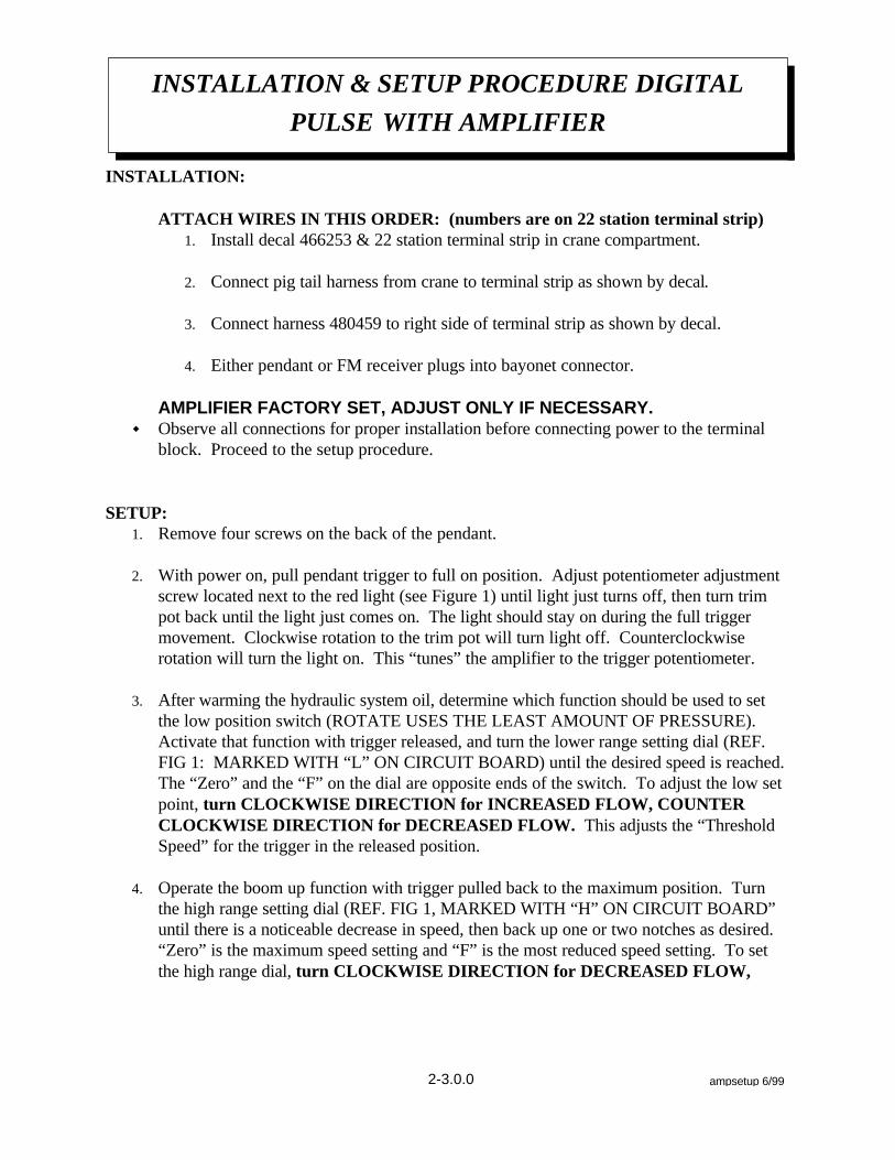
2. With power on, pull pendant trigger to full on position. Adjust potentiometer adjustmentscrew located next to the red light (see Figure 1) until light just turns off, then turn trimpot back until the light just comes on. The light should stay on during the full triggermovement. Clockwise rotation to the trim pot will turn light off. Counterclockwiserotation will turn the light on. This “tunes” the amplifier to the trigger potentiometer.
3. After warming the hydraulic system oil, determine which function should be used to setthe low position switch (ROTATE USES THE LEAST AMOUNT OF PRESSURE).Activate that function with trigger released, and turn the lower range setting dial (REF.FIG 1: MARKED WITH “L” ON CIRCUIT BOARD) until the desired speed is reached.The “Zero” and the “F” on the dial are opposite ends of the switch. To adjust the low setpoint, turn CLOCKWISE DIRECTION for INCREASED FLOW, COUNTERCLOCKWISE DIRECTION for DECREASED FLOW. This adjusts the “ThresholdSpeed” for the trigger in the released position.
4. Operate the boom up function with trigger pulled back to the maximum position. Turnthe high range setting dial (REF. FIG 1, MARKED WITH “H” ON CIRCUIT BOARD”until there is a noticeable decrease in speed, then back up one or two notches as desired. “Zero” is the maximum speed setting and “F” is the most reduced speed setting. To setthe high range dial, turn CLOCKWISE DIRECTION for DECREASED FLOW,
INSTALLATION & SETUP PROCEDURE DIGITAL
PULSE WITH AMPLIFIER
ampsetup 6/992-3.0.0
COUNTER CLOCKWISE DIRECTION FOR INCREASED FLOW. This operationadjusts the trigger “Dead Band” at the fully pulled position.
5. Replace cover and install screws.
Figure 1
INSTALLATION & SETUP PROCEDURE DIGITAL
PULSE WITH AMPLIFIER
ampsetup 6/992-3.1.0
2-2.0.0 AW766144 5/99
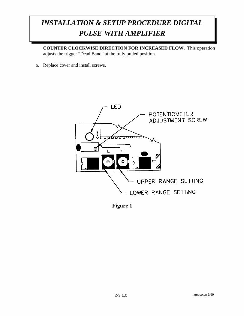
RECOMMENDED BOOM SUPPORT
P/N 766144
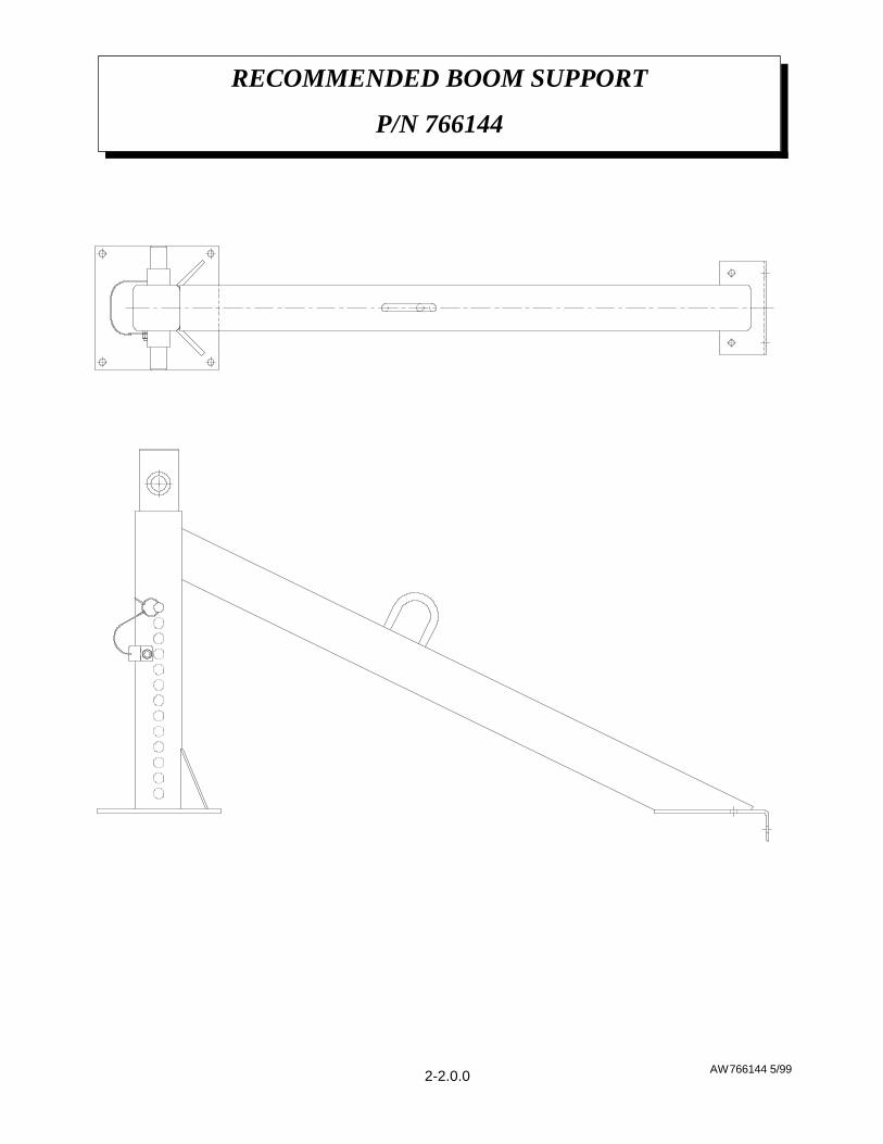
1 ANTI-2-BLOCK
A. Unplug the anti-2-block system from the overloadsystem and connect C and D to bypass theanti-2-block system.
1. If the three functions work, check continuityof anti-2-block system using continuitytester at disconnected weather packconnectors, and investigate switch at end ofboom, cable and cable reel.
2. If the three functions do not work, continueon with section #2.
2 LOAD SENSOR (Pressure Switch)
A. With crane unloaded, unplug weather packconnector on load sensor wire.
1. If the three functions work, recheck thePressure Switch by taking an ohm readingon the two wires coming from the Switch.The switch has normally open contacts, sothe reading should be the maximum. If lessthan maximum ohm reading is indicated(usually a dead short), replace the Switch.
2. If the three functions do not work, continuewith section #3.
3 RELAY BOX
A. Inside this box are two 320355 relays. Since theseare inexpensive relays, the easiest way to troubleshoot this device is to replace both relays.
1. The two relays are identical but servedifferent functions. RELAY A is the onewith the most wires going to its connector.RELAY A breaks the circuit between theground side of the solenoid valves on boomdown, extend out, and hoist up functions.This happens whenever the overload switchon the lift cylinder senses more than normalpressure indicating an overload condition.When overload happens then 12 volts ispassed through the overload switch to pull inRELAY A which then interrupts the groundcircuit of the valves controlling those
functions which could cause additionaloverload. In addition to this, when there isalso a signal from the boom down solenoid toRELAY B at the same time, RELAY Blatches RELAY A so that even if theoverload signal from the pressure switch toRELAY A is removed, RELAY A willcontinue to be on and interrupt the groundcircuit until the signal from the boom downsolenoid and pressure switch are removed.
2. The purpose of RELAY A is to interrupt theground circuit and stop hoist up, boomdown, and extend out functions fromoperating. The purpose of RELAY B is tostop boom bounce caused by the overloadsystem cycling on and off.
4 OPERATIONAL TEST AND TROUBLESHOOTING OF RELAY BOX
A. After the anti-2-block test and the load sensor testshave been performed and the overload system stilldoes not operate, check the relay box.
1. Disconnect the weatherpak connector in theload sensor pressure switch wires goingfrom the pressure switch to the relay box.Disconnect the weatherpak connectorbetween the cord reel and the relay box.
2. Check for 12 volts at pin B of load sensorconnector on relay box side of harness.Short from pin A to pin B of weatherpak.When pins A & B are shorted there shouldNOT be continuity from the cord reelweatherpak on the relay box side of theconnection to ground. When A & B are notshorted there should be continuity toground. Replace relay A if these conditionsare not met.
3. If the boom tends to bounce when boomingdown due to intermittent cycling of theoverload system, then RELAY B should bereplaced after verifying that the sense wirefrom the relay box to the boom downsolenoid valve control terminal is connected.
OVERLOAD SYSTEM / ANTI-2-BLOCK
TROUBLE SHOOTING GUIDE
OVLD 1/20002-6.0.0
IF THE THREE FUNCTIONS, BOOM DOWN, HOIST UP ANDEXTEND OUT, QUIT WORKING, the problem probably lies in either the OverloadSystem or the Anti-2-block system or both. If these three functions are NOT WORKING andmost other functions are, an investigation should be made as follows: (refer to Figure 1)
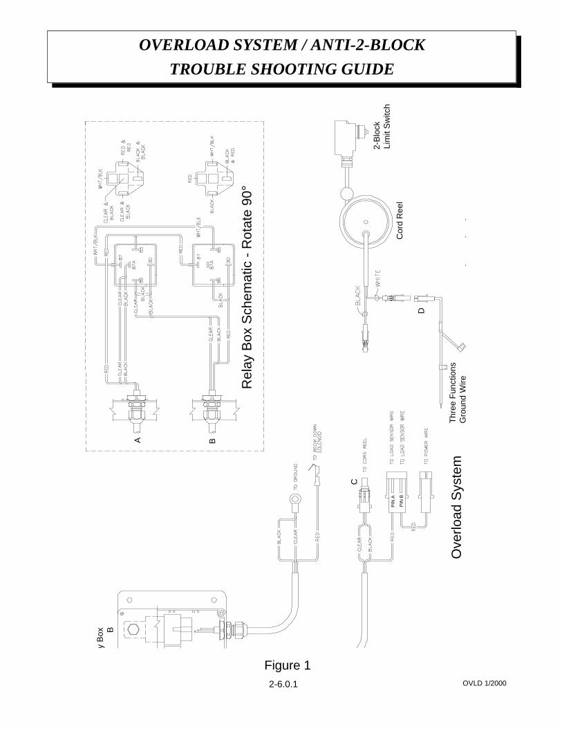
OVERLOAD SYSTEM / ANTI-2-BLOCK
TROUBLE SHOOTING GUIDE
OVLD 1/20002-6.0.1
BR
elay
Box
PIN
B
PIN
A
Rel
ay B
ox S
chem
atic
- R
otat
e 90
°
A B
C
Cor
d R
eel
2-B
lock
Lim
it S
witc
h
Ant
i-2-B
lock
Sys
tem
Ove
rload
Sys
tem
Thr
ee F
unct
ions
Gro
und
Wire
D
Figure 1
1 Obtain the proper wiring diagram and checkwiring.
2 With truck running, and master switch on, checkterminal “L” voltage.
A. If 12 - 13.75 volts, proceed.
B. If not, check for blown fuse or broken wires.
3 Install pendant, turn system power on and checkvoltage between “T & N” should read less than3 volts increasing to 9 volts when trigger ispulled.
A. If no voltage or low voltage (less than truckvoltage), make sure the power switch on theeight switch pendant is in the "on" position.
B. Then, check for loose connection in thependant or a broken wire in the pendantcable.
4 Disconnect bullet connectors on wires connect-ing from proportional valve din connector.Then ground brown wire to a chassis groundand connect blue wire to 12 volts. This shouldoperate crane at maximum speed. If not, checkproportional valve. This will send maximumcurrent thru proportional valve and should closeit completely.
OR
5 Manually override the proportional valve byturning knurled knob clockwise.
6 Check for proper crane operation.
A. If crane operates properly, proceed.
B. If not, check coil resistance from pin to pin(should be 4.7 ohms) and from pin to groundring on coil (should be infinite resistance). Ifresistance is much different than above,replace coil, then proceed.
C. Re-connect brown and blue wire.
7 The potentiometer is set by the manufacturer. Ifa problem occurs with this potentiometer, callthe Auto Crane Service Department.
8 Release trigger.
9 Set two adjustment switches ( hi & lo ) tonumber "4". (One side of the switch knob has anindicator)
10 The LO switch takes the "dead space" out of thebeginning trigger activation, and will continue toraise the low signal to give half flow with thetrigger at full released position. The higher thenumber or letter (0 thru f), the higher the flowto the crane with the trigger in the fully released position.
11 The HI switch takes the "dead space" out of thefull trigger position, and will continue to lowerthe high signal to half the flow at the maximumtrigger pulled position. The higher the numberor letter (0 thru f), the lower the flow to thecrane with the trigger in the fully pulledposition.
12 A good starting position is to have bothswitches on the number "0".
NOTE: Both switches on "F" will limit flow to amedian value and not allow any change.
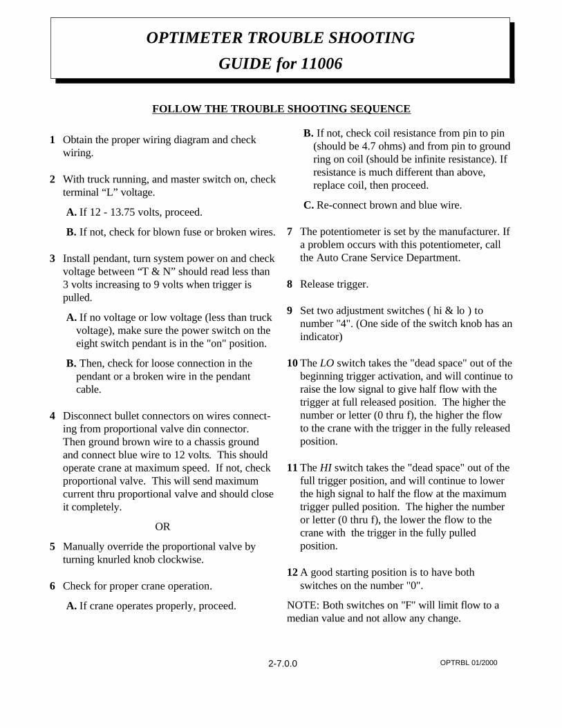
OPTRBL 01/2000
OPTIMETER TROUBLE SHOOTING
GUIDE for 11006
FOLLOW THE TROUBLE SHOOTING SEQUENCE
2-7.0.02-7.0.0
AW480533 1/99
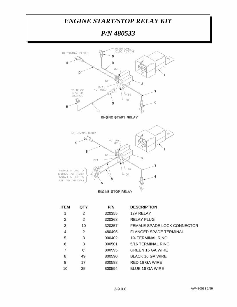
ENGINE START/STOP RELAY KIT
P/N 480533
BLUE 16 GA WIRE80059435’10
RED 16 GA WIRE80059317’9
BLACK 16 GA WIRE80059049’8
GREEN 16 GA WIRE8005956’7
5/16 TERMINAL RING 00050136
1/4 TERMINAL RING 00040235
FLANGED SPADE TERMINAL48049524
FEMALE SPADE LOCK CONNECTOR320357103
RELAY PLUG32036322
12V RELAY32035521
DESCRIPTIONP/NQTYITEM
2-9.0.0
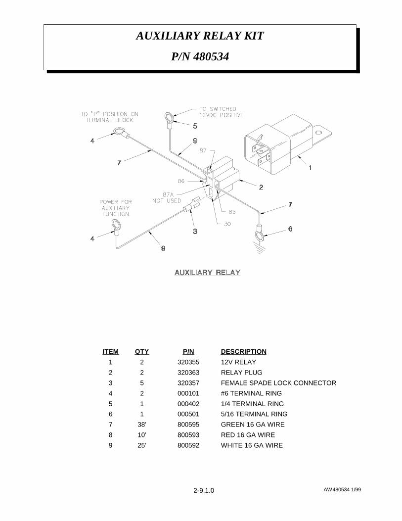
AW480534 1/99
AUXILIARY RELAY KIT
P/N 480534
WHITE 16 GA WIRE80059225’9
RED 16 GA WIRE80059310’8
GREEN 16 GA WIRE80059538’7
5/16 TERMINAL RING 00050116
1/4 TERMINAL RING 00040215
#6 TERMINAL RING00010124
FEMALE SPADE LOCK CONNECTOR32035753
RELAY PLUG32036322
12V RELAY32035521
DESCRIPTIONP/NQTYITEM
2-9.1.0
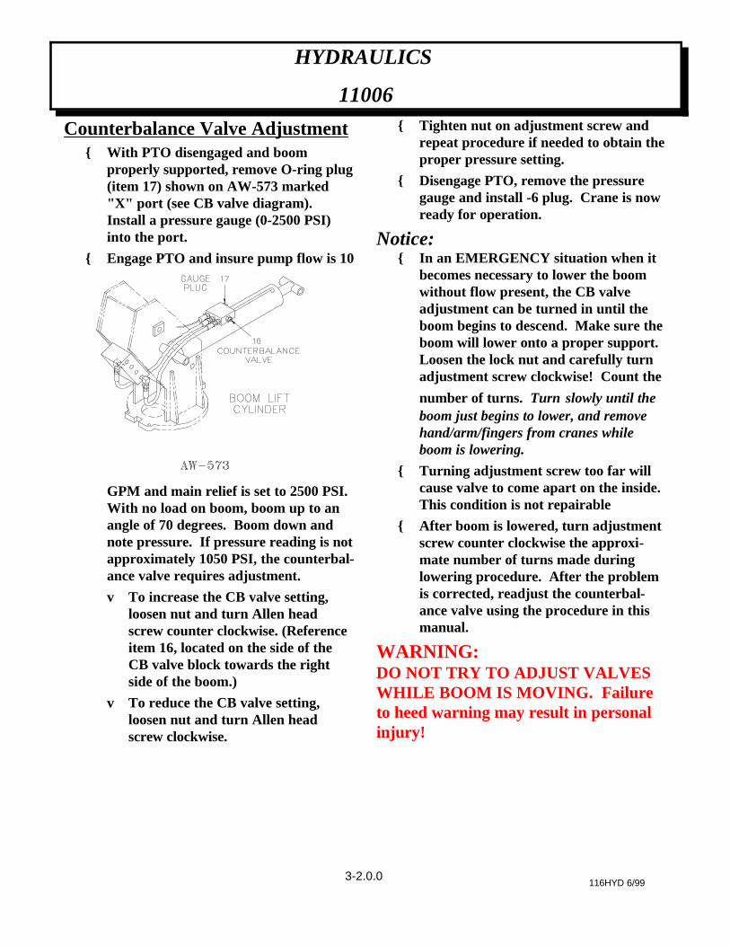
Counterbalance Valve Adjustment{ With PTO disengaged and boom
properly supported, remove O-ring plug(item 17) shown on AW-573 marked"X" port (see CB valve diagram).Install a pressure gauge (0-2500 PSI)into the port.
{ Engage PTO and insure pump flow is 10
GPM and main relief is set to 2500 PSI.With no load on boom, boom up to anangle of 70 degrees. Boom down andnote pressure. If pressure reading is notapproximately 1050 PSI, the counterbal-ance valve requires adjustment.
v To increase the CB valve setting,loosen nut and turn Allen headscrew counter clockwise. (Referenceitem 16, located on the side of theCB valve block towards the rightside of the boom.)
v To reduce the CB valve setting,loosen nut and turn Allen headscrew clockwise.
{ Tighten nut on adjustment screw andrepeat procedure if needed to obtain theproper pressure setting.
{ Disengage PTO, remove the pressuregauge and install -6 plug. Crane is nowready for operation.
Notice:{ In an EMERGENCY situation when it
becomes necessary to lower the boomwithout flow present, the CB valveadjustment can be turned in until theboom begins to descend. Make sure theboom will lower onto a proper support.Loosen the lock nut and carefully turnadjustment screw clockwise! Count the
number of turns. Turn slowly until theboom just begins to lower, and removehand/arm/fingers from cranes whileboom is lowering.
{ Turning adjustment screw too far willcause valve to come apart on the inside.This condition is not repairable
{ After boom is lowered, turn adjustmentscrew counter clockwise the approxi-mate number of turns made duringlowering procedure. After the problemis corrected, readjust the counterbal-ance valve using the procedure in thismanual.
WARNING: DO NOT TRY TO ADJUST VALVESWHILE BOOM IS MOVING. Failureto heed warning may result in personalinjury!
116HYD 6/99
HYDRAULICS
11006
3-2.0.0
CAUTION: Never check for hydraulic leaks by feeling around hoses, fittings, or any other components.High pressure oil can be injected through the skin causing severe injury, or death.
The hydraulic system of the 11006H power version is electrically operated and requires a minimum of 12V for satisfac-tory performance. The hydraulic pump is bi-rotational with a pressure relief setting of 2500 psi (Ref.). Standard pumpspeed is 1325 RPM (Ref. Pump P/N 367215). This pump is for direct flange mounting only. It is not to be shaft drivenunless it has the outboard bearing installed (367215003).
PROBLEM SOLUTIONFLOW PRESENT BUT FUNCTION WILL NOT WORK
HYDRAULIC "CHATTER"
NO FLOW OR LIMITED FLOW TOCRANE
HYDRAULIC TROUBLESHOOTING
11006
116hydtbl 12/99
Remove valve cover, P/N 466200, to gain access to the manual overrideon the end of the valve cartridge. If the pump is operating, operate therelief valve manual override or the proportional valve override and pushand twist (CCW) the directional control valve manual override to unlock,then pull to operate the function. If the function does operate, check forloose wires, low voltage or a bad ground. If the problem is traced to novoltage at the valve cartridge, remove pendant and, with the switchengaged, check for an open circuit with an ohmmeter. If the circuit isopen, check for broken wiring or a bad switch. If the function does notoperate, see the "NO FLOW" paragraph in this section.
When a hydraulic function is engaged and causes the crane to "chatter",check for a loose wire, low voltage at valve cartridge, low pump pressure,or air in the system.
Check for adequate oil supply in reservoir. Check operation of bypasssystem by using manual override on proportional valve operator onproportional valve while operating crane. If crane functions, followproportional troubleshooting procedure for the proportional valve. If thelow flow condition continues to exist when the manual override isoperated, remove relief valve cartridge and check for dirt. Other possiblecauses for a low flow condition are:1. Engine speed is too slow.
2. A blocked pressure hose from pump. This condition can be identifiedby excessive lugging of engine and rapid overheating of oil.
3. Collapsed or blocked suction hose to pump. This condition is usuallyidentified by pump cavitation noise.
4. Bad pumps: a bad pump will usually have some flow but the flow willdrop off rapidly as pressure increases. This condition will causeoverheating of the system. A drop of 4gpm or more from 0 to 2000psiis cause for pump investigation
3-3.0.0
NO PRESSURE OR TOO LOWPRESSURE
TOO HIGH FLOW
TOO HIGH PRESSURE
CAUTION
The Auto Crane 11006H series cranes are manufactured with a standard overload protection system to prevent struc-tural damage to the crane. When the crane load rating is exceeded, main boom down, extend out, and hoist up will notfunction. These operations cannot be used again until the load on the crane is reduced. Also, the main boom elevationwill be limited in its operation as the crane becomes overloaded. Attempting to raise the main boom with a load greatlyexceeding the crane rating will open the main relief valve resulting in no boom movement. This problem can beresolved by moving the load closer to the crane pedestal, or reducing the load.
HYDRAULIC TROUBLESHOOTING
11006
116hydtbl 12/99
Check to maintain adequate oil in reservoir (approx. 18 gal.), using thesight gauge. Make sure pressure gauge is functioning correctly. Possiblerelief valve stuck open. Check for excessive leakage and correct. Check toensure that pressure limit switch is correctly set.
Make sure pump size is correct and pump speed is not too fast (Consultmanufacturer's data sheet). Check or replace flow control. Check compo-nents for flow displacements. High flow may cause erratic valveoperation.
Make sure pressure relief valve is correctly set.
3-3.1.0
CHECK-TORQUE TO 180FT-LBS (DRY) AS REQUIRED
X ROTATION GEAR BOX
CHECK-TORQUE TO 150FT-LBS (DRY) AS REQUIRED
X ROTATION BEARING BOLTS
GREASE WITH MOBILPLEXEP-2 OR EQUIV. @ ZERKS
X ROTATION BEARING
CLEAN AFTER FIRST WEEK,THEN EVERY 3 MONTHS(OPTIONAL EQUIPMENT)
X HIGH PRESSURE FILTER
REPLACE ELEMENTX RETURN LINE FILTER
LUBE w/ WD-40XEXTENSION PIN
GREASE WITH MOBILPLEXEP-2 OR EQUIV. @ ZERKS
XBOOM CYLINDERPINS
CHECK AROUND CYLINDERROD FOR EXCESS FLUIDLEAKAGE
XBOOM CYLINDER
GREASE WITH MOBILPLEXEP-2 OR EQUIV. @ ZERKS
XBOOM PIVOTS
CHECK-TIGHTEN ASREQUIRED
XALL OTHER BOLTS
SEALED BEARING, REPLACEIF ROUGH OR LOOSE
XSHEAVE BEARINGS
LUBE WITH MOBILTAC LL, ORLUBRIPLATE P/N 15263, OREQUIVALENT
XROTATION RINGGEAR
CHECK-TORQUE TO 440FT-LBS (DRY) AS REQUIRED
X MOUNTING BOLTS
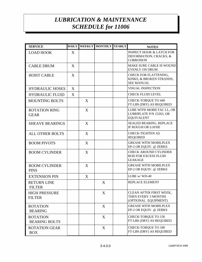
CHECK FLUID LEVELXHYDRAULIC FLUID
VISUAL INSPECTIONXHYDRAULIC HOSES
CHECK FOR FLATTENING,KINKS, & BROKEN STRANDS,SEE MANUAL
XHOIST CABLE
MAKE SURE CABLE IS WOUNDEVENLY ON DRUM
XCABLE DRUM
INSPECT HOOK & LATCH FORDEFORMATION, CRACKS, &CORROSION
XLOAD HOOK
NOTESYEARLYMONTHLYWEEKLYDAILYSERVICE PERFORMED
116MTSCH 4/99
LUBRICATION & MAINTENANCESCHEDULE for 11006
3-4.0.0
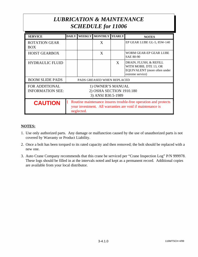
{ Routine maintenance insures trouble-free operation and protectsyour investment. All warranties are void if maintenance isneglected.
CAUTION
FOR ADDITIONAL 1) OWNER’S MANUAL INFORMATION SEE: 2) OSHA SECTION 1910.180 3) ANSI B30.5-1989
PADS GREASED WHEN REPLACEDBOOM SLIDE PADS
DRAIN, FLUSH, & REFILLWITH MOBIL DTE 13, OREQUIVALENT (more often underextreme service)
XHYDRAULIC FLUID
WORM GEAR-EP GEAR LUBESAE 80-90
XHOIST GEARBOX
EP GEAR LUBE GL-5, 85W-140X ROTATION GEAR BOX
NOTESYEARLYMONTHLYWEEKLYDAILYSERVICE PERFORMED
NOTES:
1. Use only authorized parts. Any damage or malfunction caused by the use of unauthorized parts is notcovered by Warranty or Product Liability.
2. Once a bolt has been torqued to its rated capacity and then removed; the bolt should be replaced with anew one.
3. Auto Crane Company recommends that this crane be serviced per “Crane Inspection Log” P/N 999978.These logs should be filled in at the intervals noted and kept as a permanent record. Additional copiesare available from your local distributor.
116MTSCH 4/993-4.1.0
LUBRICATION & MAINTENANCESCHEDULE for 11006

AW466144 12/99
PEDESTAL ASSEMBLY
P/N 466144 for 11006 SERIES
4-1.1.0
Val
ve B
ank
Cov
er,
P/N
466
200,
no
t sho
wn
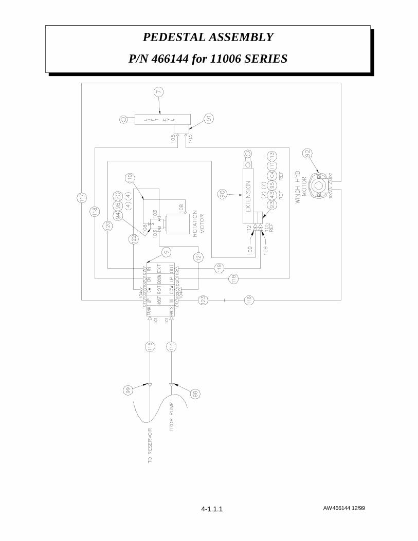
AW466144 12/99
PEDESTAL ASSEMBLY
P/N 466144 for 11006 SERIES
4-1.1.1
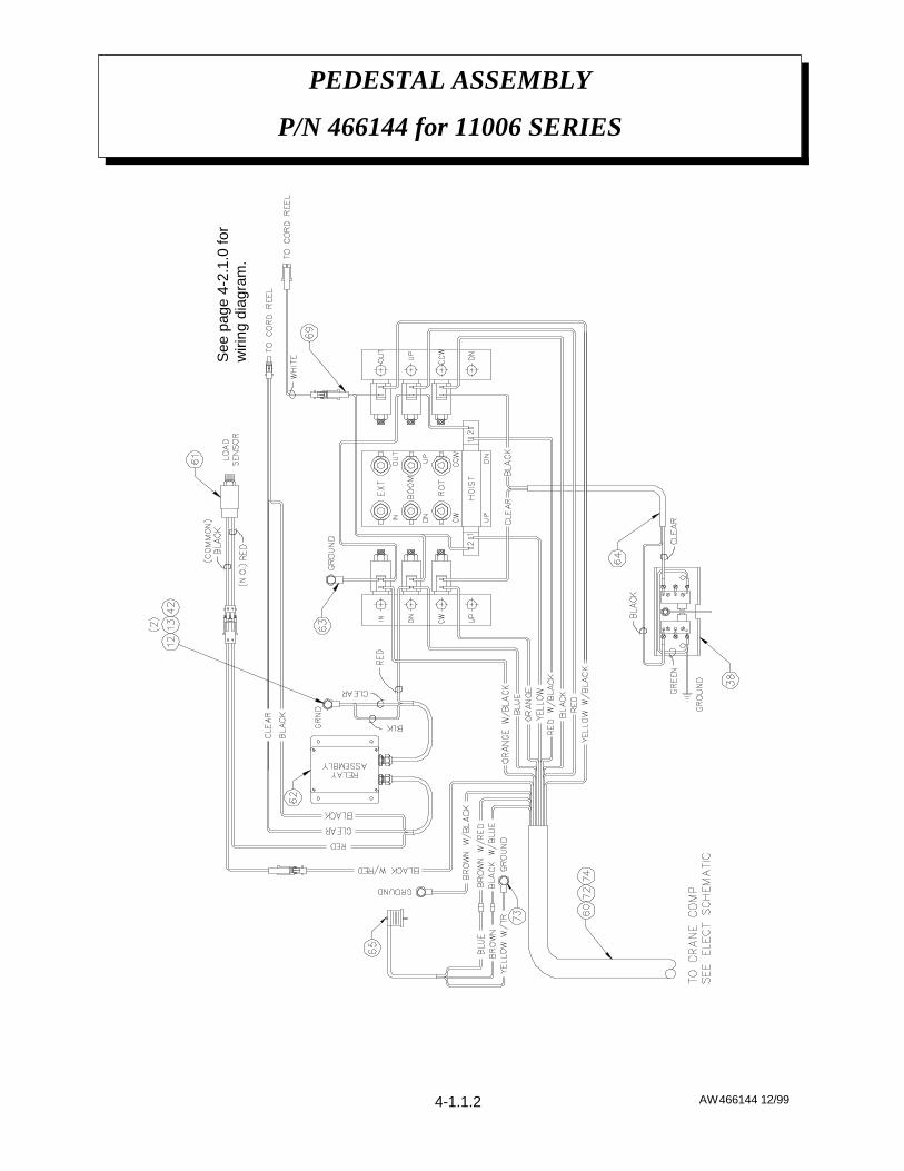
AW466144 12/99
PEDESTAL ASSEMBLY
P/N 466144 for 11006 SERIES
4-1.1.2
See
pag
e 4-
2.1.
0 fo
r w
iring
dia
gram
.

AW466144 12/99
PEDESTAL ASSEMBLY
P/N 466144 for 11006 SERIES
4-1.1.3
NUT #10 UNF015600450
ROUND HEAD SCREW #10 UNF X 5/8002609449
FLAT WASHER 3/8021200448
ELECTRICAL SCHEMATIC (466190)REFERENCE147
WASHER 1/4020200643
NUT 1/4 UNC015900 542
CABLE RETAINER480024241
SELF TAPPING CAPSCREW 1/4 UNC x 3/8002615240
CAPSCREW 3/8 UNC x 1008701639
SWITCH PANEL ASSEMBLY466203138
SWITCH COVER466198 137
ROTATION STOP466196136
CAPSCREW 3/8 UNC x 1/2008401135
HYDRAULIC MOTOR O-RING (SWING DRIVE)374103130
SOCKET HEAD SCREW 5/8 UNC x 1 1/4 006205227
SOCKET HEAD SCREW 5/8 UNC x 2 1/4367200226
CAPSCREW 5/8 UNC x 1 3/4 GR 8012198225
CAPSCREW 5/8 UNC x 2 1/4 GR 84901713724
CAPSCREW 5/8 UNC x 1 1/2 GR 8490172323
HARDENED FLAT WASHER 5/80239024622
FLAT WASHER 5/160209011021
LOCK WASHER 5/160206011620
NUT 5/160165001019
CAPSCREW 5/16 UNC x 1 1/4 GR 8007804618
NUT 3/8 UNC 330372617
LOCK WASHER 3/8021100616
CAPSCREW 3/8 UNC x 1 1/2 GR 8366159115
PEDESTAL PIN WELDMENT466152114
FLAT WASHER 1/4020300413
CAPSCREW 1/4 UNC x 3/4005500612
PEDESTAL COVER PLATE466183111
WINCH ASSEMBLY454130110
ELECTRIC DIRECTIONAL VALVE46623519
VALVE BANK MOUNTING PLATE46615118
BOOM UP CYLINDER46610117
4.5 IN.3/REV HYDRAULIC MOTOR (SWING DRIVE)36715816
SWING DRIVE36700515
SWING DRIVE SPACER PLATE46618514
PEDESTAL WELDMENT46614513
ROTATION BEARING37206412
BASE PLATE46614311
DESCRIPTIONPART NUMBERQUANTITYITEM

AW466144 12/99
PEDESTAL ASSEMBLY
P/N 466144 for 11006 SERIES
4-1.1.4
TEE -6 OR(M)/-6 JIC(M) RUN (241168)REFERENCE1112
90° ELBOW -6 NPT/-6 JIC(M) (200892REFERENCE1111
SWING DRIVE HOSE ASSEMBLY 3740681110
45° ELBOW -6 JIC(M)/-8 JIC SWIVEL (330647)REFERENCE2109
90° ELBOW -4 JIC/-4 JIC(M)3691272108
90° ELBOW -10 OR(M)/-8 JIC(M)3720442107
STRAIGHT ADAPTER -8 OR(M)/-8 JIC(M)2008762105
90° ELBOW -6 JIC SWIVEL/-6 JIC(M) LG4801942104
90° ELBOW -10 OR(M)/-6 JIC(M) 4801982103
ADAPTER -8 OR(M)/-6 JIC(M)2027566102
90° ELBOW -8 JIC (M)/-8 OR(M)3620204101
BULKHEAD ADAPTER -12 JIC(M)/-12 JIC(M)374079199
BULKHEAD ADAPTER -10 JIC(M)/-10 JIC(M)466182198
SOCKET HEAD SCREW 5/16 -18 UNC X 2 1/4367163496
CAPSCREW 1/4-20 UNC X 1 ¾ (005810)REFERENCE295
COUNTERBALANCE VALVE ROTATION367124194
COUNTERBALANCE VALVE (EXTENSION CYLINDER) (367407)REFERENCE193
HYDRAULIC MOTOR WINCH REFERENCE192
COUNTERBALANCE VALVE CARTRIDGE (LIFT CYLINDER)360223191
POWER EXTENSION CYLINDER (466100)REFERENCE190
CONDUIT NUT 3/4466184174
TERMINAL RING 14-3/8000601173
CORD CONNECTOR 370433172
NUT #8 UNC015500471
WIRE ASSEMBLY WITH WEATHER PAC466220169
DIN PLUG ASSEMBLY466237165
CONDUCTOR ASSEMBLY466193164
GROUND WIRE ASSEMBLY466194163
RELAY BOX ASSEMBLY466236162
LOAD SENSOR ASSEMBLY466209161
CRANE PIGTAIL WIRING HARNESS466195160
LOCK WASHER 1/2021500254
SOCKET HEAD SCREW ½ -13 UNC X 1 1/4367185253
HOLE PLUG 1 1/8 DIAMETER466246152
LOCK WASHER #10019800451
DESCRIPTIONPART NUMBERQUANTITY
ITEM

Notes: Item Numbers not used: 28, 29, 31, 32, 33, 34, 44, 45, 46, 55, 56, 57, 58, 59, 66, 67, 68, 70, 75, 76, 77,78, 79, 80, 81, 82, 83, 84, 85, 86, 87, 88, 89, 97, 100, 106.Valve Bank Cover, P/N 466200, not shown.
AW466144 12/99
PEDESTAL ASSEMBLY
P/N 466144 for 11006 SERIES
4-1.1.5
TUBE ASSEMBLY -8 HOIST4662391123
HOSE ASSEMBLY (F)JIC/(F)JIC 90° ELBOW (LONG) X 15812206-0151122
HOSE ASSEMBLY (F)JIC/(F)JIC 90° ELBOW (LONG) X 16812206-0161121
HOSE ASSEMBLY (F)JIC/(F)JIC 90° ELBOW (LONG) X 33812206-0331120
HOSE ASSEMBLY (F)JIC SWIVEL/(F)JIC 90° ELBOW (SHORT) X 33812209-0331119
HOSE ASSEMBLY (F)JIC SWIVEL/(F)JIC 90° ELBOW (SHORT) X 36812209-0362118
HOSE ASSEMBLY (F)JIC SWIVEL/(F)JIC 90° ELBOW (SHORT) X 20812309-0201117
HOSE ASSEMBLY (M)JIC/(F)JIC 90° ELBOW (LONG) X 16812312-0161116
HOSE ASSEMBLY -12(F)/-8 JIC(F) 90°E LBOW X 15812327-0161115
HOSE ASSEMBLY -10(F)/-8 JIC(F) 90° ELBOW (SHORT) X 16812328-0161114
TUBE ASSEMBLY (480212)REFERENCE1113
DESCRIPTIONPART NUMBERQUANTITYITEM
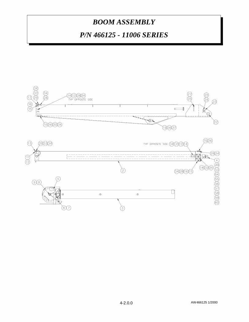
AW466125 1/2000
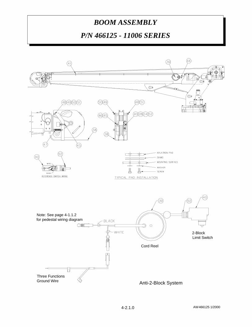
BOOM ASSEMBLY
P/N 466125 - 11006 SERIES
4-2.0.0
AW466125 1/2000
BOOM ASSEMBLY
P/N 466125 - 11006 SERIES
Three FunctionsGround Wire
2-BlockLimit Switch
Anti-2-Block System
Cord Reel
Note: See page 4-1.1.2 for pedestal wiring diagram
4-2.1.0

AW466125 1/2000
BOOM ASSEMBLY
P/N 466125 - 11006 SERIES
4-2.2.0
2-BLOCK SWITCH ASSEMBLY466243140
CORD REEL ASSEMBLY366973-001139
2-BLOCK WELDMENT466135138
NYLOCK NUT 3/8 UNC (370538)REF137
CAPSCREW 3/8 UNC x 1 1/2 GR8 (366159)REF136
LOCK WASHER 1/2021500835
LOCK WASHER 1/40202002834
FLAT WASHER 1/4020300433
CAPSCREW 124 UNF x 1 1/2010201832
CAPSCREW ¼ UNF x 1/2005406431
CAPSCREW ¼ UNF x 3/4005501430
CAPSCREW ¼ UNF x 1005601429
CAPSCREW ¼ UNF x 5/80051021628
HEX LOCK NUT ¼ UNC016300227
ANGLE INDICATOR360038226
RETAINING RING480029225
EXTENSION CYLINDER PIN480129124
SPACER480121223
GREASE ZERK239000122
---21
STEEL-POWER BOOM PAD 466186 220
BOOM / CYLINDER PIN (466126)REF119
EXTENSION CYLINDER RETAINER480105218
BOOM PAD366201117
LARGE SHIM .032 THICK480033616
LARGE NYLATRON BOOM PAD480032415
SMALL NYLATRON BOOM PAD480036414
POWER BOOM PAD480118113
SMALL SHIM .032 THICK (use as required)4800371012
STEEL PAD 3 x 2 x 5/16 THICK 466218111
MANUAL BOOM PIN480030110
NUT ¾ UNF01860019
CAPSCREW ¾ UNF x 501440018
BLOCK PIN36012517
HITCH PIN36012416
SHEAVE ASSEMBLY 7/16 ROPE46613015
POWER EXTENSION CYLINDER46610014
MANUAL BOOM 46611613
POWER BOOM 46611512
LOWER BOOM 46611011
DESCRIPTIONP/NQTYITEM
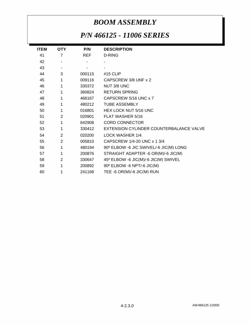
AW466125 1/2000
BOOM ASSEMBLY
P/N 466125 - 11006 SERIES
TEE -6 OR(M)/-6 JIC(M) RUN 241168 160
90º ELBOW -6 NPT/-6 JIC(M)200892159
45º ELBOW -6 JIC(M)/-6 JIC(M) SWIVEL330647258
STRAIGHT ADAPTER -6 OR(M)/-6 JIC(M)200876157
90º ELBOW -6 JIC SWIVEL/-6 JIC(M) LONG480194156
CAPSCREW 1/4-20 UNC x 1 3/4005810255
LOCK WASHER 1/4020200254
EXTENSION CYLINDER COUNTERBALANCE VALVE330412153
CORD CONNECTOR642908152
FLAT WASHER 5/16020901251
HEX LOCK NUT 5/16 UNC016801150
TUBE ASSEMBLY480212149
CAPSCREW 5/16 UNC x 7466167148
RETURN SPRING360824147
NUT 3/8 UNC330372146
CAPSCREW 3/8 UNF x 2009116145
#15 CLIP000115344
- --43
- --42
D-RINGREF741
DESCRIPTIONP/NQTYITEM
4-2.3.0

ASSEMBLY INSTRUCTIONS:1. Winch has right hand worm and gear. Cable spools over drum. Use number
one slots for brake balls(7) in cam plate(2).2. Install brake hub(5) through brake housing(4) on winch worm with key.3. Assemble balls(7) in cam plate(2) using hard grease to hold balls in place.4. Place cam plate(2) on brake hub(5), matching its holes with the balls.5. Install thrust plate(16).6. Thread capscrew(10) with jam nut (12) and thread seal (11) through housing
cover(3).7. Place gasket(15) on housing cover(3).8. Install coil spring(9) on capscrew(10).9. Install flat spring(1) on capscrew(10).
10. Secure retainer plate(6) and flat spring(1) to housing cover(3) usingcapscrews(8) and washers(14).
11. Using capscrews(8) and thead seals(13) attach housing cover(3) to brakehousing(4).
12. Test brake by shifting winch to UP then DOWN to see if brake is working inproper rotation. If not, remove housing cover(3) and locate brake balls(7) inopposite set of slots of cam plate(2).
13. Adjust to suit by tightening or loosening capscrew(10) on outside of housingcover(3). When proper adjustment is obtained, secure capscrew(10) with jamnut(12).
AUTOMATIC SAFETY BRAKE ASSEMBLY
(OIL COOLED) HOIST
AW368 1/994-3.1.0
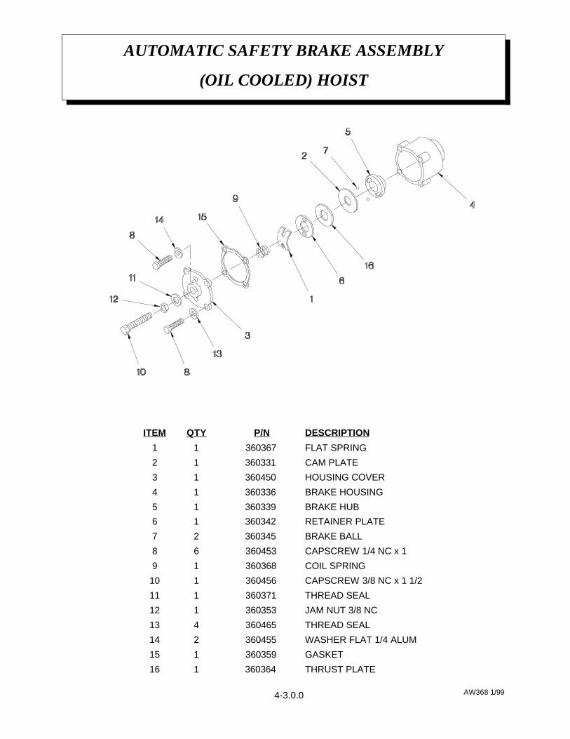
AUTOMATIC SAFETY BRAKE ASSEMBLY
(OIL COOLED) HOIST
AW368 1/99
THRUST PLATE360364 116
GASKET360359 115
WASHER FLAT 1/4 ALUM360455 214
THREAD SEAL360465 413
JAM NUT 3/8 NC360353 112
THREAD SEAL360371 111
CAPSCREW 3/8 NC x 1 1/2 360456 110
COIL SPRING360368 19
CAPSCREW 1/4 NC x 1 360453 68
BRAKE BALL360345 27
RETAINER PLATE360342 16
BRAKE HUB360339 15
BRAKE HOUSING360336 14
HOUSING COVER360450 13
CAM PLATE360331 12
FLAT SPRING360367 11
DESCRIPTIONP/NQTYITEM
4-3.0.0
AW466175 1/2000
HOIST ACTUATOR
P/N 466175 - MODEL 11006
4-4.0.0

AW466175 1/2000
HOIST ACTUATOR
P/N 466175 - MODEL 11006
KEY367488221
OUTPUT SHAFT367487120
RIGHT HAND WORM367474119
OIL SEAL367466118
PIPE PLUG367465117
PIPE PLUG367464116
REDUCER367463115
QUAD RING367462214
RELIEF FITTING367461113
GASKET367460112
GASKET367459211
CAPSCREW 5/16-18 UNC X 1 1/4367458610
CAPSCREW 5/16-18 UNC X ¾36745789
BALL BEARING36745628
ROUND END KEY36745527
GEAR HOUSING36745416
RIGHT HAND GEAR36745315
COVER36745214
BUSHING36745123
ADAPTER36745012
COUPLING ASSEMBLY36744911
DESCRIPTIONPART NUMBERQUANTITYITEM
4-4.1.0

AW466175 1/2000
HOIST ACTUATOR
P/N 466175 - MODEL 11006
4-4.1.0
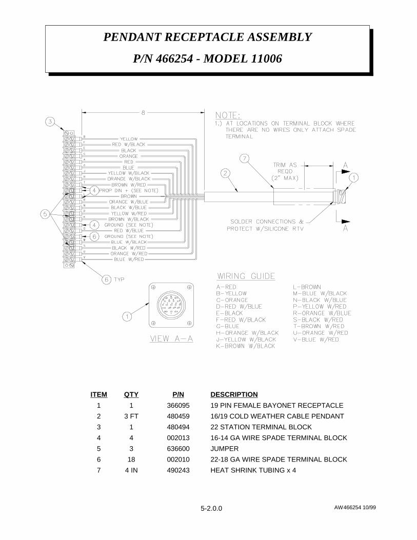
AW466254 10/99
PENDANT RECEPTACLE ASSEMBLY
P/N 466254 - MODEL 11006
HEAT SHRINK TUBING x 44902434 IN7
22-18 GA WIRE SPADE TERMINAL BLOCK002010186
JUMPER63660035
16-14 GA WIRE SPADE TERMINAL BLOCK00201344
22 STATION TERMINAL BLOCK48049413
16/19 COLD WEATHER CABLE PENDANT4804593 FT2
19 PIN FEMALE BAYONET RECEPTACLE36609511
DESCRIPTIONP/NQTYITEM
5-2.0.0
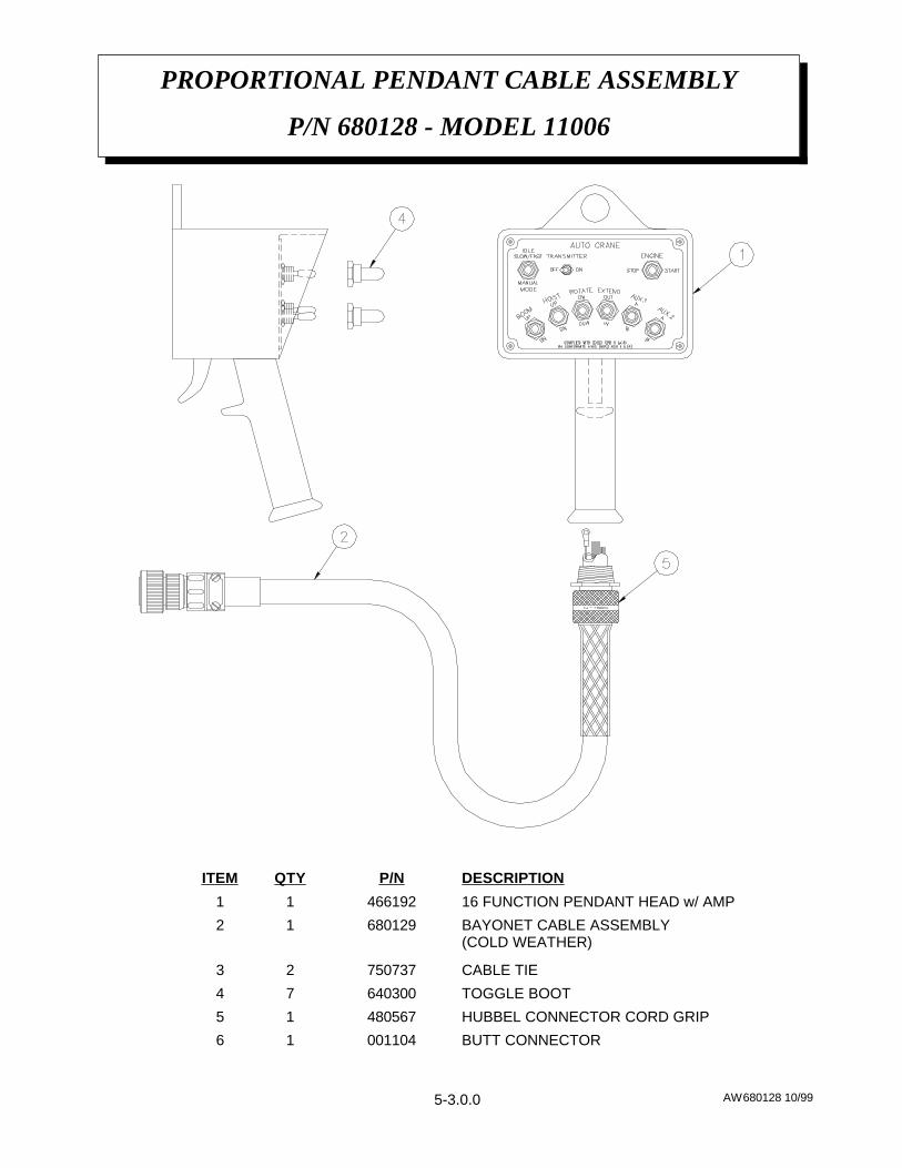
AW680128 10/99
PROPORTIONAL PENDANT CABLE ASSEMBLY
P/N 680128 - MODEL 11006
BUTT CONNECTOR00110416
HUBBEL CONNECTOR CORD GRIP48056715
TOGGLE BOOT64030074
CABLE TIE75073723
BAYONET CABLE ASSEMBLY (COLD WEATHER)
68012912
16 FUNCTION PENDANT HEAD w/ AMP46619211
DESCRIPTIONP/NQTYITEM
5-3.0.0
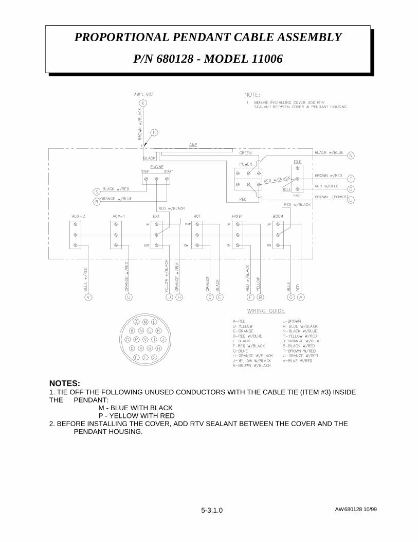
NOTES:1. TIE OFF THE FOLLOWING UNUSED CONDUCTORS WITH THE CABLE TIE (ITEM #3) INSIDETHE PENDANT:
M - BLUE WITH BLACKP - YELLOW WITH RED
2. BEFORE INSTALLING THE COVER, ADD RTV SEALANT BETWEEN THE COVER AND THE PENDANT HOUSING.
AW680128 10/99
PROPORTIONAL PENDANT CABLE ASSEMBLY
P/N 680128 - MODEL 11006
5-3.1.0
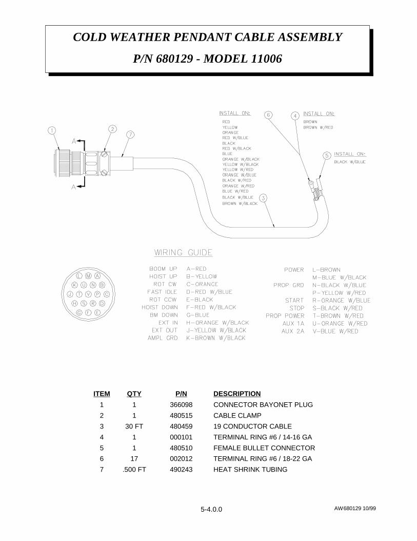
AW680129 10/99
COLD WEATHER PENDANT CABLE ASSEMBLY
P/N 680129 - MODEL 11006
HEAT SHRINK TUBING490243.500 FT7
TERMINAL RING #6 / 18-22 GA002012176
FEMALE BULLET CONNECTOR48051015
TERMINAL RING #6 / 14-16 GA00010114
19 CONDUCTOR CABLE48045930 FT3
CABLE CLAMP48051512
CONNECTOR BAYONET PLUG36609811
DESCRIPTIONP/NQTYITEM
5-4.0.0
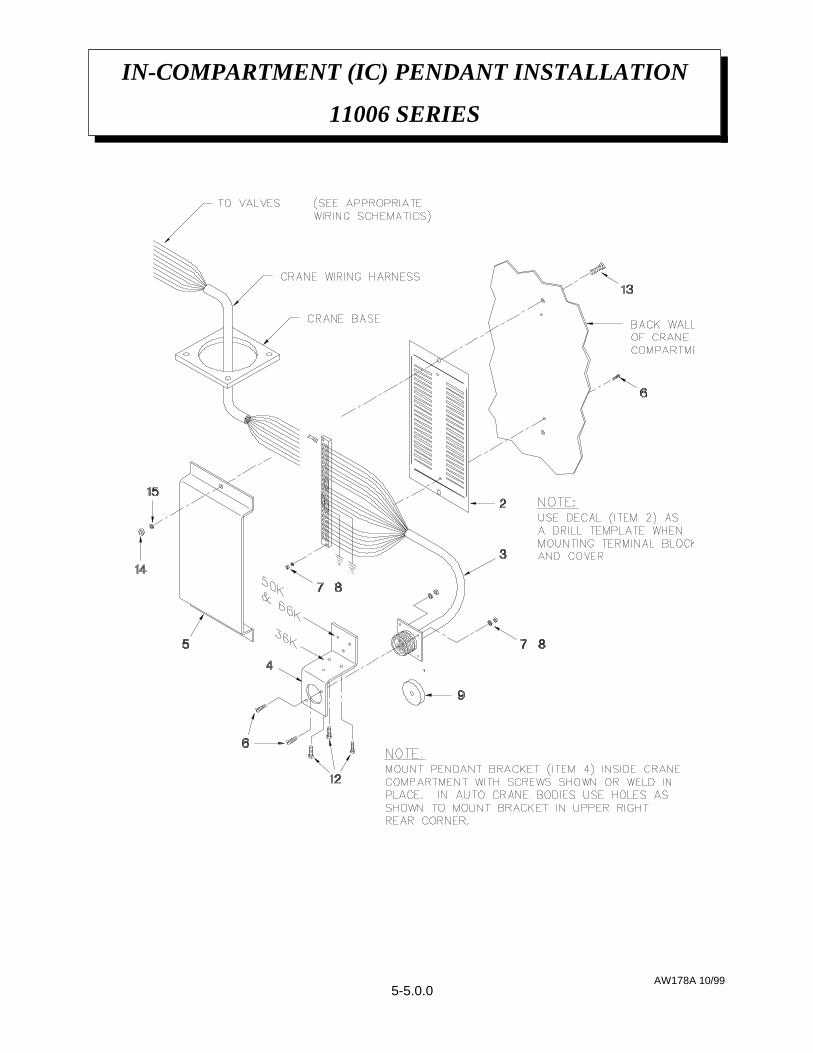
AW178A 10/99
IN-COMPARTMENT (IC) PENDANT INSTALLATION
11006 SERIES
5-5.0.0

AW178A 10/99
IN-COMPARTMENT (IC) PENDANT INSTALLATION
11006 SERIES
SPLIT LOCK WASHER 1/4020200215
HEX NUT 1/4-20 NC015900214
CAPSCREW 1/4-20 NC x 3/4 G5005500213
CAPSCREW #10-24 NC x 3/4 SELF TAPPING330038312
WIRE TIE x 7" 634401611
WIRE TIE STICK ON RETAINER750738610
19 PIN RECEPTACLE CAP36609719
SPLIT LOCK WASHER #601960048
HEX NUT #6-32 NC01540047
ROUND HEAD SCREW #6-32 NC x 5/8 00040446
22 STATION TERMINAL BLOCK COVER48049315
PENDANT BRACKET48062614
22 STATION / 19 PIN SOCKET HARNESS48045913
22 STATION TERMINAL BLOCK DECAL46625312
---1
DESCRIPTIONP/NQTYITEM
5-5.1.0
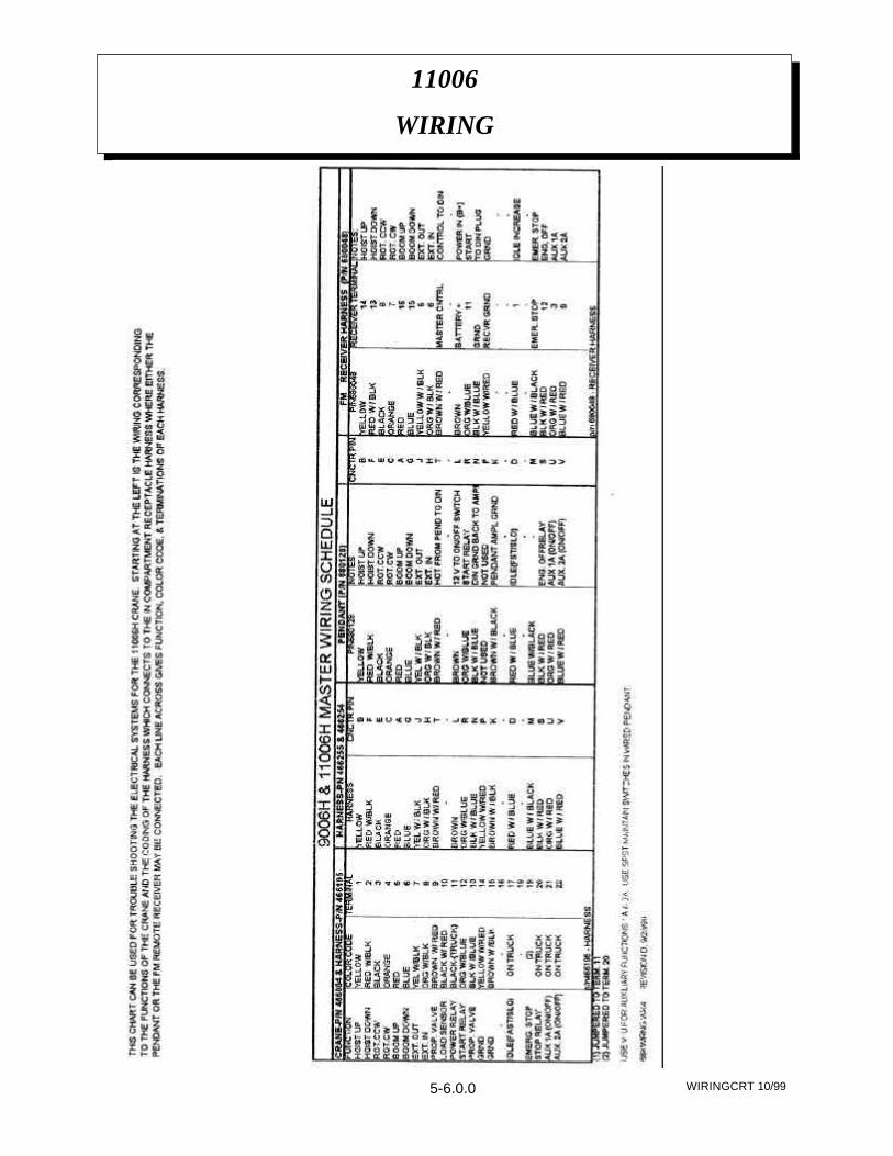
WIRINGCRT 10/99
11006
WIRING
5-6.0.0
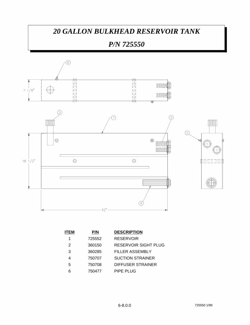
6-8.0.0 725550 1/99
20 GALLON BULKHEAD RESERVOIR TANK
P/N 725550
PIPE PLUG750477 6
DIFFUSER STRAINER750708 5
SUCTION STRAINER750707 4
FILLER ASSEMBLY360285 3
RESERVOIR SIGHT PLUG360150 2
RESERVOIR725552 1
DESCRIPTIONP/NITEM
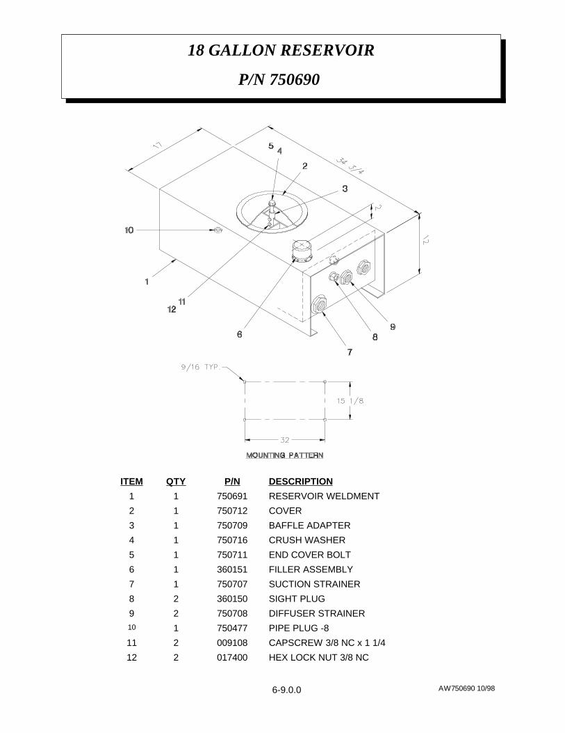
AW750690 10/98
18 GALLON RESERVOIR
P/N 750690
6-9.0.0
HEX LOCK NUT 3/8 NC017400212
CAPSCREW 3/8 NC x 1 1/4009108211
PIPE PLUG -8750477110
DIFFUSER STRAINER75070829
SIGHT PLUG36015028
SUCTION STRAINER75070717
FILLER ASSEMBLY36015116
END COVER BOLT75071115
CRUSH WASHER75071614
BAFFLE ADAPTER75070913
COVER75071212
RESERVOIR WELDMENT75069111
DESCRIPTIONP/NQTYITEM
AW766081 5/99
HYDRAULIC OUTRIGGERS
CURBSIDE CRANE - P/N 766081
7-1.0.0

AW766081 5/99
HYDRAULIC OUTRIGGERS
CURBSIDE CRANE - P/N 766081
SELF TAPPING SCREW #10-24 x 3/4320371434
HEX HEAD NUT 5/16016500333
SPLIT LOCK WASHER 5/16020601332
HEX HEAD SCREW 5/16811029331
90º ADAPTER -8 JICM/-8 ORM362020230
45º ADAPTER -8 SWIVEL /-8 JIC MALE369394129
CAP -8360445228
SCREW 3/8 x 1/2 UNC008401227
45º ADAPTER -6 ORB/-6 JIC480195626
CAUTION “STAND CLEAR” DECAL040581225
CAUTION DECAL759017224
DANGER DECAL759016223
STREET/CURB COVER766046222
VALVE COVER766128121
90º ADAPTER -6 JIC MALE/-6 JIC SWIVEL480194420
BULK HEAD STRAIGHT ADAPTER -6 MALE/-6 MALE320734419
90º BULK HEAD ADAPTER -6 MALE/-6 MALE367136418
HOSE ASSEMBLY -6 FEMALE/-6 FEMALE812026-016417
90º ELBOW HOSE ASSEMBLY -6 FEMALE/-6 FEMALE (812209-018)
REF116
90º ELBOW ADAPTER -6 ORM/-6 JIC MALE241175115
90º EXTRA LONG ELBOW ADAPTER -6 JIC/-6 JIC MALE330645114
45º SWIVEL ELBOW ADAPTER -6 JIC330647113
SPLIT LOCK WASHER 5/8023800112
FLAT WASHER 5/8 x 1 3/4021802311
HOSE ASSEMBLY -6 FEMALE/-6 FEMALE812026-081410
SCREW 5/8 x 2 1/449017119
HEX NUT 3/833037228
SPLIT LOCK WASHER 3/802110047
FLAT HEAD SCREW 3/8 x 100830026
TRUNNION MOUNT76610915
VALVE BANK76617214
CURB SIDE SLIDE ASSEMBLY76617313
STREET SIDE SLIDE ASSEMBLY76617412
BODY WELDMENT 766016REF11
DESCRIPTIONP/NQTYITEM
7-1.1.0
AW766202 10/99
HYDRAULIC OUTRIGGERS
STREETSIDE CRANE - P/N 766202
7-1.2.0

AW766202 10/99
HYDRAULIC OUTRIGGERS
STREETSIDE CRANE - P/N 766202
SELF TAPPING SCREW #10-24 x 3/4320371434
HEX HEAD NUT 5/16016500333
SPLIT LOCK WASHER 5/16020601332
CAPSCREW 5/16811029331
90º ADAPTER -8 JICM/-8 ORM362020230
45º ADAPTER -8 SWIVEL /-8 JIC MALE369394129
CAP -8360445228
SCREW 3/8 x 1/2 UNC008401227
45º ADAPTER -6 ORB/-6 JIC480195626
CAUTION “STAND CLEAR” DECAL040581225
CAUTION DECAL759017224
DANGER DECAL759016223
STREET/CURB COVER766046222
VALVE COVER766128121
90º ADAPTER -6 JIC MALE/-6 JIC SWIVEL480194420
BULK HEAD STRAIGHT ADAPTER -6 MALE/-6 MALE320734419
90º BULK HEAD ADAPTER -6 MALE/-6 MALE367136418
HOSE ASSEMBLY -6 FEMALE/-6 FEMALE812026-016417
90º ELBOW HOSE ASSEMBLY -6 FEMALE/-6 FEMALE (812209-018)
REF116
90º ELBOW ADAPTER -6 ORM/-6 JIC MALE241175115
90º EXTRA LONG ELBOW ADAPTER -6 JIC/-6 JIC MALE330645114
45º SWIVEL ELBOW ADAPTER -6 JIC330647113
SPLIT LOCK WASHER 5/8023800112
FLAT WASHER 5/8 x 1 3/4021802311
HOSE ASSEMBLY -6 FEMALE/-6 FEMALE812026-081410
SCREW 5/8 x 2 1/449017119
HEX NUT 3/833037228
SPLIT LOCK WASHER 3/802110047
FLAT HEAD SCREW 3/8 x 100830026
TRUNNION MOUNT76610915
VALVE BANK76617214
CURB SIDE SLIDE ASSEMBLY76617313
STREET SIDE SLIDE ASSEMBLY76617412
BODY WELDMENT 766400REF11
DESCRIPTIONP/NQTYITEM
7-1.3.0
7-2.0.0 AW766081b 6/99
HYDRAULIC OUTRIGGERS FLOW DIAGRAM
11006 SERIES
TANK
STREET SIDEOUTRIGGER
OUTRIGGERCURB SIDE
CURB SIDE
STREET SIDEOUTRIGGER
OUTRIGGER
HANDLE SIDE
SELECTOR VALVEP/N 480236
AW466230 1/99
TRAVELING BLOCK ASSEMBLY
P/N 466230 - MODEL 11006
LOCK NUT 3/8 NC017301210
SCREW 3/8 NC x 481102329
ROUND TUBING 1 1/4 x .120W x 1 1/2 L46623318
PIN BLOCK 1 DIA46623227
HITCH PIN36012446
HEX LOCK NUT 3/4 NF01860015
SHEAVE BOLT w/ ZERK FITTING 3/4 NF x 449031314
SIDE PLATE TRAVELING BLOCK46623123
5 TON SWIVEL HOOK48002612
SHEAVE BLOCK ASSEMBLY49025611
DESCRIPTIONP/NQTYITEM
8-1.0.0
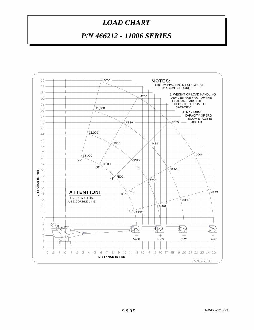
AW466212 6/99
LOAD CHART
P/N 466212 - 11006 SERIES
9-9.9.9
5400 4000 3125 2475
15°
30°
45°
60°
75°
5650
4200
6200
47007500
565010,000
7500
11,000
11,000
11,000
5850
4450
3750
3350
DISTANCE IN FEET
DIS
TA
NC
E IN
FE
ET
NOTES:1.BOOM PIVOT POINT SHOWN AT
8'-0" ABOVE GROUND
2. WEIGHT OF LOAD HANDLING DEVICES ARE PART OF THE LOAD AND MUST BE DEDUCTED FROM THE CAPACITY
OVER 5500 LBS. USE DOUBLE LINE
9000
4700
2650
3000
3550
ATTENTION!
3. MAXIMUMCAPACITY OF 3RD
BOOM STAGE IS 9000 LB.