Embed Size (px)
Citation preview

2003 OWNERS MANUAL
Manual No. 999951 Rev. 9/2/2003
Serial No. __________________ Mailing Address: P.O. Box 580697 Tulsa, OK 74158-0697 Physical Address: Phone (918) 836-0463 4707 N. Mingo Rd. Fax (918) 834-5979 Tulsa, OK 74117-5904 http://www.autocrane.com


To: Fax:From: Date:Re: Pages:
Name: Phone:Address:City: State: Zip:Contact:
Name:Address:City: State: Zip:Contact:
VIN #
ONE REGISTRATION FORM PER UNIT (CRANE OR BODY)Registration form must be mailed or faxed within 15 days of customer installation.
Mail to:Warranty DepartmentAuto Crane Company
P.O. Box 581510Tulsa, OK 74158-0697
Date Product Delivered: Date Processed:** For Auto Crane use only
Product Information: (Required for Warranty Activation)
Model No.: Serial No.:
E-mail Address:
Distributor Information: (Required for Warranty Activation)
Product Registration
E-mail Address:
(Required for Warranty Activation)
Auto Crane Warranty Registration
(918) 834-5979Warranty Department
End User Information:
Fax Transmission
Warranty Registration Rev. 072403


2003 SERIES OWNER’S MANUAL – REVISION RECORD
i
Revision Date
Section(s) Or
Page(s) Description of Change
09/02/03 Last page New 2-year warranty policy to replace 1-year warranty policy


WARNINGS
READ THIS PAGEWarnings 12/2002
WARNING! Federal law (49 cfr part 571) requires that the Final Stage Manufacturer of a vehiclecertify that the vehicle complies with all applicable federal regulations. Any modifications performedon the vehicle prior to the final state are also considered intermediate stage manufacturing and mustbe certified as to compliance. The installer of this crane and body is considered on of themanufacturers of the vehicle. As such a manufacturer, the installer is responsible for compliancewith all applicable federal and state regulations, and is required to certify that the vehicle is incompliance.
WARNING! It is the further responsibility of the installer to comply with the OSHA Truck CraneStability Requirements as specified by 29 CFR part 1910.180 (C) (1).
WARNING! NEVER OPERATE THE CRANE NEAR ELECTRICAL POWER LINES!Death or serious injury will result from boom, line, or load contacting electric lines. Do not use cranewithin 10 feet (3.05m) of electric power lines carrying up to 50,000 volts. One foot additionalclearance is required for every additional 30,000 volts or less. SEE DANGER DECAL (P/N 040529)in this Owner's Manual.
WARNING! NEVER.........................................♦ EXCEED load chart capacities (centerline of rotation to hoist hook).♦ Un-reel last 5 wraps of cable from drum!♦ Wrap cable around load!♦ Attempt to lift or drag a load from the side! The boom can fail far below its rated capacity.♦ Weld, modify, or use unauthorized components on any Auto Crane unit! This will void any
warranty or liability. Also failure of the crane may result.♦ Place a chain link on the tip of the hook and try to lift a load!♦ Use a sling bar or anything larger than the hook throat that could prevent the hook latch from
closing, thus negating the safety feature!♦ Hold on any pendant Select Switch that will cause unsafe operating conditions!
WARNING! In using a hook with latch, ALWAYS make sure that the hook throat is closed beforelifting a load! Proper attention and common sense applied to the use of the hoist hook and variousslings will prevent possible damage to material being hoisted and may prevent injury to personnel.
WARNING! Failure to correctly plumb and wire crane can cause inadvertent operation and damageto crane and/or personnel!
WARNING! Auto Crane Company remote controlled cranes are not designed or intended to beused for any applications involving the lifting or moving of personnel.
WARNING! ALWAYS operate the crane in compliance with the load capacity chart. DO NOT USEthe overload shutdown device to determine maximum rated loads, if the crane is equipped with thistype of device.


TABLE OF CONTENTS2003 SERIES
6-11-2003
INTRODUCTION 1-1
SAFETY TIPS AND PRECAUTIONS 2-1
OPERATING PRACTICES & WARNINGS 2-3
OPERATION OF UNIT / OUTRIGGERS 2-4
QUALIFICATIONS FOR OPERATORS 2-5
INSPECTION, TESTING, AND MAINTENANCE 2-8
SAFETY DECAL SECTION 3-1
GENERAL DIMENSIONS 3-4
MOUNTING AND INSTALLATION 3-5
LUBERCATION AND MAINTENCE SCHEDULE 3-7
GENERAL ASSEMBLY 4-1
HOIST ASSEMBLY 7-1
MANUAL BRAKE ASSEMBLY 7-4
ELECTRICAL SCHEMATIC 8-1
PENDANT CONTROL ASSMEBLY 8-3
LOAD CHART 10-1
WARRANTY LAST PAGE


INTRODUCTION2003 SERIES
1-16/26/2003
Auto Crane products are designed to providemany years of safe, trouble-free, dependableservice when properly used and maintained. To assist you in obtaining the best servicefrom your crane and to avoid untimely craneand/or vehicle failure, this manual provides thefollowing operating and service instructions. It isspecifically recommended that all operating andservice personnel consider this manual asmandatory material for reading and study beforeoperating or servicing Auto Crane products. It ishighly recommended that crane owners,equipment managers and supervisors also readthis manual. Auto Crane has incorporated several safetyfeatures in the 2003 crane for your protection. For your convenience the overall dimensionsof the 2003 crane are included on the GeneralDimension Drawing. Rotation and turning radiusare also listed on that drawing. Remember, the crane adds weight to thevehicle. Adding weight may change the drivingand riding characteristics of the vehicle unlessthe appropriate overload spring(s) are installedon the truck. The payload of the vehicle isreduced by the weight of the crane. The operatorshould exercise care when loading the vehicle.Distributing the payload on the vehicle evenlywill greatly improve the driving and ridingcharacteristics of the vehicle.Auto Crane Company issues alimited warranty certificate with eachunit sold. See last page for warranty The 2003 cranes are attached directly to your12 volt truck electrical system. The power cableis included with the crane. The 2003 is anotherhighly efficient Auto Crane product. The use ofa maintenance-free battery is not recommendedfor use on any Auto Crane product. Therecommended alternator and battery that willgive the longest life with the most useful dutycycle is a 75 amp alternator with a 500 coldcranking amp battery. These specificationsshould be considered minimum. It has always been Auto Crane Companypolicy to handle all warranty claims we receiveas promptly as possible. If a warranty claiminvolves discrepant material or workmanship,Auto Crane will take immediate correctiveaction. It is understandable that Auto CraneCompany cannot assume responsibility ofliability when it is obvious that our products
have been abused, misused, overloaded orotherwise damaged by inexperienced personstrying to operate the equipment without readingthe manual.
Auto Crane will not assumeresponsibility or liability for anymodifications or changes made to unit,or installation of component parts donewithout authorization.
Auto Crane maintains a strongdistributor network and a knowledgeableCustomer Service Department. In most cases, anequipment problem is solved via phoneconversation with our customer servicedepartment. The customer service departmentalso has the ability to bring a local distributor, aregional sales manager, or a factory servicemaninto the solution of an equipment problem. If,through no fault of Auto Crane Company, it isnecessary to send an experienced factoryserviceman on a field service call, the rates statedin the Auto Crane Distributor's Flat Rate Manualwill apply.
Auto Crane Company's extensiveResearch and Development Program allow ourcustomers to use the best equipment on themarket. Our Engineering Staff and ourknowledgeable sales people, are always availableto our customers in solving crane and winch-typeapplication problems. When in doubt, call theAuto Crane factory.
DISTRIBUTOR ASSISTANCE: Should you require any assistance not givenin this manual, we recommend that you consultyour nearest Auto Crane Distributor. Ourdistributors sell authorized parts and have servicedepartments that can solve almost any neededrepair.
NOTE: THIS MANUAL SHOULD REMAIN
WITH THE CRANE AT ALL TIMES. This manual does not cover all maintenance,operating, or repair instructions pertinent to allpossible situations. If you require additionalinformation, please contact the Auto CraneCompany at the following telephone number:(918) 836-0463. The information contained inthe manual is in effect at the time of thisprinting. Auto Crane Company reserves the rightto update this material without notice orobligation.

GENERAL SPECIFICATIONS2003 SERIES
1-26/26/2003
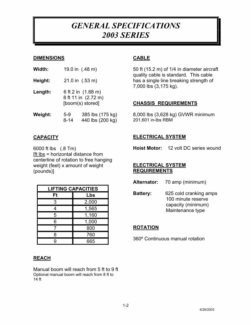
DIMENSIONS
Width: 19.0 in (.48 m)
Height: 21.0 in (.53 m)
Length: 6 ft 2 in (1.88 m) 8 ft 11 in (2.72 m) [boom(s) stored]
Weight: 5-9 385 lbs (175 kg) 8-14 440 lbs (200 kg)
CAPACITY
6000 ft lbs (.8 Tm)[ft lbs = horizontal distance fromcenterline of rotation to free hangingweight (feet) x amount of weight(pounds)]
Ft Lbs3 2,0004 1,5655 1,1606 1,0007 8008 7609 665
LIFTING CAPACITIES
REACH
Manual boom will reach from 5 ft to 9 ftOptional manual boom will reach from 8 ft to14 ft
CABLE
50 ft (15.2 m) of 1/4 in diameter aircraftquality cable is standard. This cablehas a single line breaking strength of7,000 lbs (3,175 kg).
CHASSIS REQUIREMENTS
8,000 lbs (3,628 kg) GVWR minimum201,601 in-lbs RBM
ELECTRICAL SYSTEM
Hoist Motor: 12 volt DC series wound
ELECTRICAL SYSTEMREQUIREMENTS
Alternator: 70 amp (minimum)
Battery: 625 cold cranking amps 100 minute reserve capacity (minimum) Maintenance type
ROTATION
360º Continuous manual rotation

--- IMPORTANT ---SAFETY TIPS AND PRECAUTIONS
2-112/2002
1. No unqualified or unauthorized person shall beallowed to operate the crane.
2. WARNING: Never weld, modify, or useunauthorized components / parts on any Auto Craneunit. This will void any warranty or liability. Also,failure of the crane may result.
3. Make certain the vehicle meets minimum chassisrequirements. (These requirements do not guaranteeunit stability.)
4. Make certain the crane is installed per factoryspecifications. Contact your local distributor or theAuto Crane factory if any questions arise.
5. Visual inspections and tests should be conducted atthe beginning of each shift each day to ensure that thecrane and all its operating systems are in goodcondition and working order before it is used.
6. Inspect hydraulic hoses frequently for signs ofdeterioration, and replace them as required.
7. If a hydraulic break occurs, leave the area of thebreak and do not attempt to stop the break by hand asthe hydraulic oil may be hot and under high pressurewhich can cause serious injury. Shut the systemdown as soon as possible.
8. Check the hook at least every thirty days fordistortions or cracks and replace it as required.
9. Oil gears as required.10. Stop all operations when cleaning, adjusting or
lubricating the machine.11. Keep dirt and grit out of moving parts by keeping a
crane clean. Make sure machine is free of excess oil,grease, mud and rubbish, thus reducing accidents andfire hazards.
12. When a new cable is installed, operate first with alight load to let the cable adjust itself.
13. Locate the vehicle at the work site for the beststability possible.
14. Keep the vehicle in a level position while loading orunloading.
15. Observe operating area for obstructions and/or powerlines that might be a hazard
16. WARNING: NEVER OPERATE THE CRANENEAR ELECTRICAL POWER LINES. Auto CraneCompany recommends that the crane never be anycloser to a power line (including telephone lines) than10 feet at any point.
17. Allow the vehicle engine to warm up beforeoperating crane.
18. Know the weight of your rigging and load to avoidoverloading the crane.
19. Deduct the weight of the load handling equipmentfrom the load rating to determine how much weightcan be lifted.
20. All load ratings are based on crane capacity, NOT thevehicle stability.Remember in lifting a heavy load, the weight cancreate enough tipping moment to overturn the vehicle
21. Always comply with load chart capacities, (centerlineof rotation to hook).
22. Secure all loads before lifting.23. Always set the emergency brake before beginning
operation.24. Keep objects and personnel clear of crane path during
operation.25. Operate control levers slowly and smoothly in order
to meter oil flow for safe operation.26. Always use outriggers from vehicle to the ground
during crane operation. Ensure that they are firmlypositioned on solid footings. Stand clear ofoutriggers while they are being extended.
27. If any outrigger, when extended, rests on a curb orother object that prevents it from extending to itsmaximum distance, shorten bearing or fulcrum pointand reduce the maximum load accordingly.
28. When an outrigger will not reach the ground due toholes or grades, it shall be blocked up to providelevel and firm support for the truck.
29. When working in soft earth, use wide pads underoutrigger feet to prevent sinking.
30. Always store outriggers before transportation.
WARNING!Auto Crane Company cranes are not designed or intended for use in lifting or moving persons. Any such useshall be considered to be improper and the seller shall not be responsible for any claims arising there from.This sale is made with the express understanding that there is no warranty that the goods shall be fit for thepurpose of lifting or moving persons or other improper use and there is no implied warranty or responsibilityfor such purposes.

--- IMPORTANT ---SAFETY TIPS AND PRECAUTIONS
2-212/2002
31. Always store the crane in its stowed position fortransportation.
32. Remember the overall height of the entire unit forgarage door clearance or when moving underobjects with low overhead clearance
33. Disengage power takeoff (PTO) before movingthe vehicle.
34. Always walk around the vehicle before moving.35. Never drive with a load suspended from crane.36. Do not take your eyes off a moving load. Look
in the direction you are moving.37. Never swing a load over people.38. Do not stop the load sharply in midair so that it
swings like a pendulum. Meter the control leversto avoid this situation.
39. Crane boom length should be kept as short aspossible for maximum lifting capacity and greatersafety. Longer booms require additional care inaccelerating and decelerating the swing motion,and thus slow down the working cycle and reduceproductivity.
40. Keep the load directly and vertically under theboom point at all times. Crane booms aredesigned primarily to handle vertical loads, notside lifts.WARNING: Never attempt to lift, drag, tow orpull a load from the side. The boom can fail farbelow its rated capacity.
41. Do not push down on anything with boomextensions, lift or outer boom function.
42. Do not lift personnel with any wire ropeattachment or hook. There is no impliedwarranty or responsibility for such purposes.
43. WARNING: In using a safety hook, ALWAYSclose the hook throat before lifting a load. Properattention and common sense applied to the use ofthe hook and various slings will prevent possibledamage to material being hoisted and mayprevent injury to personnel.
44. WARNING: Never place a chain link on the tipof the hook and try to lift a load with the hoist.
45. WARNING: Never use a sling bar or anythinglarger than the hook throat which could preventthe safety latch from closing, thus negating thesafety feature.
46. If the crane is equipped with an optional winch: do NOT allow personnel to ride on
loadline, hook, load, or any other deviceattached to winch line.
do NOT extend boom without reeling offline at the same time when using winch.
do pull load-block up against the boom tip.47. Do not wrap the wire rope around sharp objects
when using winch.48. WARNING: Never unreel last 5 wraps of cable
from drum.

--- IMPORTANT ---OPERATING PRACTICES AND WARNINGS
2-312/2002
1. Make certain the vehicle meets minimum chassisrequirements. (These requirements do not guarantee unitstability)
2. Make certain the crane is installed per factoryspecifications. Contact your local Distributor or theAuto Crane factory if any questions arise.
3. Keep the vehicle in as level a position as possible whileloading or unloading.
4. ALWAYS set the vehicle emergency brake beforebeginning crane operations.
5. ALWAYS use outriggers from vehicle to the groundduring crane operation. Make sure they are firmlypositioned on solid footings.
6. All load ratings are based on crane capacity, NOTtruck/crane stability.
7. Keep objects and personnel clear of crane path duringoperation.
8. Keep hoist cable pulled tight at all times.9. REMEMBER, in lifting a heavy load, the weight can
create enough tipping momentum to overturn thevehicle.
10. ALWAYS keep load as close to ground as possible.11. Hydraulic hoses need to be inspected frequently for signs
of deterioration, and be replaced as required.12. The hoist hook is an important item that an operator
should consider and use properly. It should be checkedon a daily basis for distortion or cracks.
13. ALWAYS store outriggers before road travel.
14. WARNING! NEVER OPERATE THE CRANENEAR ELECTRICAL POWER LINES! Death orserious injury will result from boom, line, or loadcontacting electric lines. Do not use crane within 10feet (3.05m) of electric power lines carrying up to50,000 volts. One foot additional clearance is requiredfor every additional 30,000 volts or less.
15. WARNING! NEVER EXCEED load chartcapacities (centerline of rotation to hoist hook).
16. WARNING! NEVER un-reel last 5 wraps of cablefrom drum!
17. WARNING! NEVER wrap cable around load!18. WARNING! NEVER attempt to lift or drag a load
from the side! The boom can fail far below its ratedcapacity.
19. WARNING! NEVER weld, modify, or useunauthorized components on any Auto Crane unit!This will void any warranty or liability. Also failureof the crane may result.
20. WARNING! NEVER place a chain link on the tip ofthe hook and try to lift a load!
21. WARNING! NEVER use a sling bar or anythinglarger than the hook throat that could prevent the hooklatch from closing, thus negating the safety feature!
22. WARNING! In using a hook with latch, ALWAYSinsure that the hook throat is closed before lifting aload! Proper attention and common sense applied tothe use of the hoist hook and various slings willprevent possible damage to material being hoisted andmay prevent injury to personnel. Switch on that willcause unsafe operating conditions!WARNING! NEVER hold any Control SelectSwitch on that will cause unsafe operating conditions!
WARNING!Auto Crane Company remote controlled, stiff boom
cranes are not designed or intended to be used for anyapplications involving the lifting or moving of personnel.

--- IMPORTANT ---OPERATION OF UNIT
2-412/2002
1. Make sure this manual has been thoroughly read byall crane operating personnel and supervisors.
2. A routine inspection of the crane should bemandatory before each operating day. Any defectsshould be corrected immediately.
3. At a job site the vehicle should be positioned so thatthe crane can adequately reach the load within therated capacity (centerline of rotation to hoist hook).
4. Keep the vehicle as level as possible duringoperation.
5. For electric cranes, engage emergency brake andleave ignition on with transmission in neutral (or inpark for automatic transmissions). Activate anycrane power switches. For Auto Crane unitsrequiring battery and hydraulic operation, engageemergency brake, place gear selector in neutral,press clutch, activate PTO, release clutch and afterhydraulic fluid is warm, set throttle control to properengine speed.
6. Always use outriggers from the truck to the ground.Be sure these are firm and adequately positioned.When rotating, keep load as low to the ground aspossible.
7. Remove the transmitter from cab or storage area.Power transmitter on. Detach hook from dead man.Crane is now ready for operation.
8. Always boom up before rotating so the boom willclear the required boom support.
9. When extending the boom, always maintain clearancebetween the boom crown and the traveling block orhoist hook.
10. Always observe safe and practical operation to avoidpossible accidents. Refer to Safety Tips andPrecautions.
11. After completing lifting operations, return the boom tostowed position on the boom support. Avoidunneeded pressure on the boom support.
12. Store transmitter in proper location (in cab or storagearea).
13. Return outriggers to stowed position. Make sure theyare pinned in place or jacklegs are returned tocompartment.
14. Check work area for any tools or equipment notstored.
15. Release throttle control, depress clutch and disengagePTO. Deactivate any crane power switches.
16. Report any unusual occurrence during crane operationthat may indicate required maintenance or repair.
17. NEVER use two cranes to support a load too large foreither crane.
OPERATION OFOUTRIGGERS
For hydraulic outriggers: 1. Shift crane/outrigger control valve to
"outrigger" position. 2. Operate the outrigger control valves (located
on the outrigger cylinders) to position theoutriggers.
3. After outriggers are positioned, returncrane/outrigger selector to "crane" position.
4. Crane is now ready to operate.
For manual outriggers: 1. Pull lock pins to release jack leg or drop down
outrigger and move to outermost lock position. 2. Make sure lock pins are reinstalled properly. 3. Lower outrigger pad to firm ground and adjust
foot to take out slack. 4. Crane is now ready to operate.

QUALIFICATIONS FOR AND CONDUCT OF OPERATORSAND OPERATING PRACTICES
OPERATORS
1. Crane operation shall be limited to personnel withthe following minimum qualifications:
A. Designated persons.B. Trainees under the direct supervision of a
designated person.C. Maintenance and test personnel (when it is
necessary in the performance of their duties).D. Inspectors (crane).
2. No one other than the personnel specified aboveshall enter the operating area of a crane with theexception of persons such as oilers, supervisors,and those specified persons authorized bysupervisors whose duties require them to do so andthen only in the performance of their duties andwith the knowledge of the operator or otherpersons.
QUALIFICATIONS FOR OPERATORS
3. Operators shall be required by the employer topass a practical operating examination.Qualifications shall be limited to the specific type ofequipment for which examined.
4. Operators and operator trainees shall meet thefollowing physical qualifications:
A. Vision of at least 20/30 Snellen in one eye and20/50 in the other, with or without correctivelenses.
B. Ability to distinguish colors, regardless of position,if colors differentiation is required for operation.
C. Adequate hearing with or without hearing aid forthe specific operation.
5. Evidence of physical defects or emotionalinstability which render a hazard to operator orothers, which in the opinion of the examiner couldinterfere with the operator's performance may besufficient cause for disqualification. In such cases,specialized clinical or medical judgment and testsmay be required.
6. Evidence that the operator is subject to seizures orloss of physical control shall be sufficient reason fordisqualification. Specialized medical tests may berequired to determine these conditions.
7. Operators and operator trainees should havenormal depth perception, coordination, and no
tendencies to dizziness or similar undesirablecharacteristics.
8. In addition to the above listed requirements, theoperator shall:
A. Demonstrate the ability to comprehend andinterpret all labels, operator's manuals, safetycodes and other information pertinent to correctcrane operations.
B. Possess knowledge of emergency procedures andimplementation of same.
C. Demonstrate to the employer the ability to operatethe specific type of equipment.
D. Be familiar with the applicable safety regulations.E. Understand responsibility for maintenance
requirements of crane.F. Be thoroughly familiar with the crane and its
control functions.G. Understand the operating procedures as outlined
by the manufacturer.
CONDUCT OF OPERATORS
9. The operator shall not engage in any practice,which will divert his attention while actuallyoperating the crane.
10. Each operator shall be responsible for thoseoperations under the operator's direct control.Whenever there is any doubt as to safety, theoperator shall consult with the supervisor beforehandling the loads.
11. The operator should not leave a suspended loadunattended unless specific precautions have beeninstituted and are in place.
12. If there is a warning sign on the switch or enginestarting controls, the operator shall not close theswitch or start the engine until the warning signhas been removed by the appointed person.
13. Before closing the switch or starting the engine,the operator shall see that all controls are in the"OFF" or neutral position and all personnel arein the clear.
14. If power fails during operation, the operator shall:A. move power controls to the "OFF" or neutral
position.B. land the suspended load and boom, if practical.
2-512/2002

QUALIFICATIONS FOR AND CONDUCT OF OPERATORSAND OPERATING PRACTICES
15. The operator shall be familiar with the equipmentand its proper care. If adjustments or repairs arenecessary, the operator shall report the samepromptly to the appointed person, and shall alsonotify the next operator.
16. All controls shall be tested by the operator at thestart of each shift. If any controls do not operateproperly, they shall be adjusted or repairedbefore operations are begun
17. Stabilizers shall be visible to the operator whileextending or setting unless operator is assisted bya signal person.
OPERATING PRACTICESHANDLING THE LOAD
18. Size of load
A. No crane shall be loaded beyond the rated loadexcept for test purposes.
B. The load to be lifted is to be within the rated loadof the crane and its existing configuration.
C. When loads which are not accurately known areto be lifted, the person responsible for the jobshall ascertain that the weight of the load does notexceed the crane rated load at the radius at whichthe load is to be lifted.
19. Attaching the load
A. The load shall be attached to the hook by meansof slings or other devices of sufficient capacity.
B. Hoist rope shall not be wrapped around the load.
20. Moving the load
A. The operator shall determine that:B. The crane is level and, where necessary, the
vehicle/carrier is blocked properly.C. The load is well secured and balanced in the
sling or lifting device before it is lifted morethan a few inches.
D. Means are provided to hold the vehiclestationary while operating the crane.
E. Before starting to lift, the hook shall broughtover the load in such a manner as to minimizeswinging.
F. During lifting care shall be taken that:
1. There is no sudden acceleration ordeceleration of the moving load.
2. Load, boom or other parts of the crane donot contact any obstruction.
G. Cranes shall not be used for dragging loadssideways.
H. This standard recognizes that articulating boomcranes are designed and intended for handlingmaterials. They do not meet personnel lift orelevator requirements. Therefore, no lifting,lowering, swinging or traveling shall be donewhile a person is on the hook or load. Hookattached suspended work platforms (baskets)shall not be used with cranes covered by thisstandard. Work platforms attached to the boommust be approved by crane manufacturer.
I. The operator should avoid carrying loads overpeople.
J. When the crane is so equipped, the stabilizersshall be fully extended and set. Blocking understabilizers shall meet the requirements asfollows:1. Strong enough to prevent crushing.2. Of such thickness, width and length as to
completely support the stabilizer pad.K. Firm footing under all tires, or individual
stabilizer pads should be level. Where such afooting is not otherwise supplied, it should beprovided by timbers, cribbing, or other structuralmembers to distribute the load so as to notexceed allowable bearing capacity or theunderlying material.
L. In transit, the boom shall be carried in stowedposition.
M. When rotating the crane, sudden starts and stopsshall be avoided. rotational speed shall be suchthat the load does not swing out beyond theradius at which it can be controlled.
N. The crane shall not be transported with a load onthe hook unless recommended by themanufacturer.
O. No person should be permitted to stand or passunder a suspended load.
21. Stowing procedure. Follow the manufacturer'sprocedure and sequence when stowing and un-stowing the crane
2-612/2002

QUALIFICATIONS FOR AND CONDUCT OF OPERATORSAND OPERATING PRACTICES
MISCELLANEOUSOPERATING NEAR ELECTRICAL POWERLINES
22. Cranes shall be operated so that no part of thecrane or load enters into the danger zone shownabove.
EXCEPTIONS
A. The danger zone may be entered after confirmationby an appointed person that the electrical distributionand transmission lines have been de-energized andvisibly grounded at the point of work; or
B. The danger zone may be entered if insulatingbarriers (not a part of nor an attachment to the crane)have been erected to prevent physical contact withthe lines.
23. For lines rated 50 kV or below, minimumclearance between the lines and any part of thecrane or load (including handling appendages)shall be 10-ft. (3m). For higher voltages, seeTable1.
24. Caution shall be exercised when working nearoverhead lines, because they can movehorizontally or vertically due to wind, moving thedanger zone to new positions.
25. In transit with no load and boom lowered theclearance shall be specified in Table 1.
26. A qualified signalperson shall be assigned toobserve the clearance and give warning beforeapproaching the above limits.
A. Any overhead wire shall be considered to be anenergized line unless and until the personowning such line or the electrical utilityauthorities verify that it is not an energized line.
B. Exceptions to this procedure, if approved by theadministrative or regulatory authority if thealternate procedure provides equivalentprotection and set forth in writing.
C. Durable signs shall be installed at the operator'sstation and on the outside of the crane, warningthat electrocution or serious bodily injury mayoccur unless a minimum clearance of 10 ft.(3.0m) between the crane or the load beinghandled and energized power lines. Greaterclearances are required because of highervoltage as stated above. These signs shall berevised but not removed when local jurisdictionrequires greater clearances.
normal voltage, kV(phase to phase) ft (m)
over to 50 10 (3.50)over 50 to 200 15 (4.6)over 200 to 350 20 (6.1)over 350 to 500 25 (7.62)over 500 to 750 35 (10.67)over 750 to 1000 45 (13.72)
over to 0.75 4 (1.22)over 0.75 to 50 6 (1.83)over 50 to 345 10 (3.83)over 345 to 750 16 (4.87)over 750 to 1000 20 (6.1)
while in transit with no load and boom lowered
TABLE 1minimum required
____clearance____
when operating near high voltage poower lines
2-712/2002

INSPECTION, TESTING AND MAINTENANCEGENERAL
INSPECTION CLASSIFICATION
1. Initial inspection. Prior to initial use, all new,altered, modified or extensively repaired cranesshall be inspected by a designated person toinsure compliance with provisions of thisstandard.
2. Regular inspection. Inspection procedure forcranes in regular service is divided into twogeneral classifications based upon the intervalsat which inspection should be performed. Theintervals in turn are dependent upon the natureof the components of the crane and the degreeof their exposure to wear, deterioration, ormalfunction. The two general classifications areherein designated as "frequent" and "periodic"with respective intervals between inspectionsas defined below.A. frequent inspection - daily to monthly intervalsB. periodic inspection - one to twelve intervals or
as specifically recommended by themanufacturer
FREQUENT INSPECTION
3. Inspection shall be performed by designatedpersonnel.A. control mechanisms for maladjustment
interfering with proper operation - daily, whenused
B. control mechanisms for excessive wear ofcomponents and contamination by lubricants orother foreign matter
C. safety devices for malfunctionD. all hydraulic hoses, particularly those which flex
in normal operation of crane functions, shouldbe visually inspected once every working day,when used
E. hooks and latches for deformation, chemicaldamage, cracks, and wear. Refer toANSI/ASME B30.10
F. rope reeving for compliance with cranemanufacturer's specifications, if optional winchis used
G. electrical apparatus for malfunctioning, signs ofexcessive deterioration, dirt and moistureaccumulation
H. hydraulic system for proper oil level and leaksdaily
I. tires for recommended inflation pressure, cutsand loose wheel nuts
J. connecting pins and locking device for wear anddamage
PERIODIC INSPECTION
4. Deformed, cracked or corroded members in thecrane structure and carrier
5. Loose bolts, particularly mounting bolts.6. Cracked or worn sheaves and drums.7. Worn, cracked, or distorted parts such as pins,
bearings, shafts, gears, rollers and devices.8. Excessive wear on brake and clutch system
parts and lining.9. Crane hooks inspected for cracks.10. Travel steering, braking, and locking devices,
for malfunction.11. Excessively worn or damaged tires.12. Hydraulic and pneumatic hose, fittings, and
tubing inspection.A. evidence of leakage at the surface of the
flexible hose or its junction with metal andcoupling
B. A. blistering, or abnormal deformation to theouter covering of the hydraulic or pneumatichose
C. A. leakage at threaded or clamped joints thatcannot be eliminated by normal tightening orrecommended procedures
D. A. evidence or excessive abrasion or scrubbingon the outer surface of a hose, rigid tube, orfitting. Means shall be taken to eliminate theinterference of elements in contact or otherwiseprotect the components
2-812/2002
INSPECTION, TESTING AND MAINTENANCEGENERAL
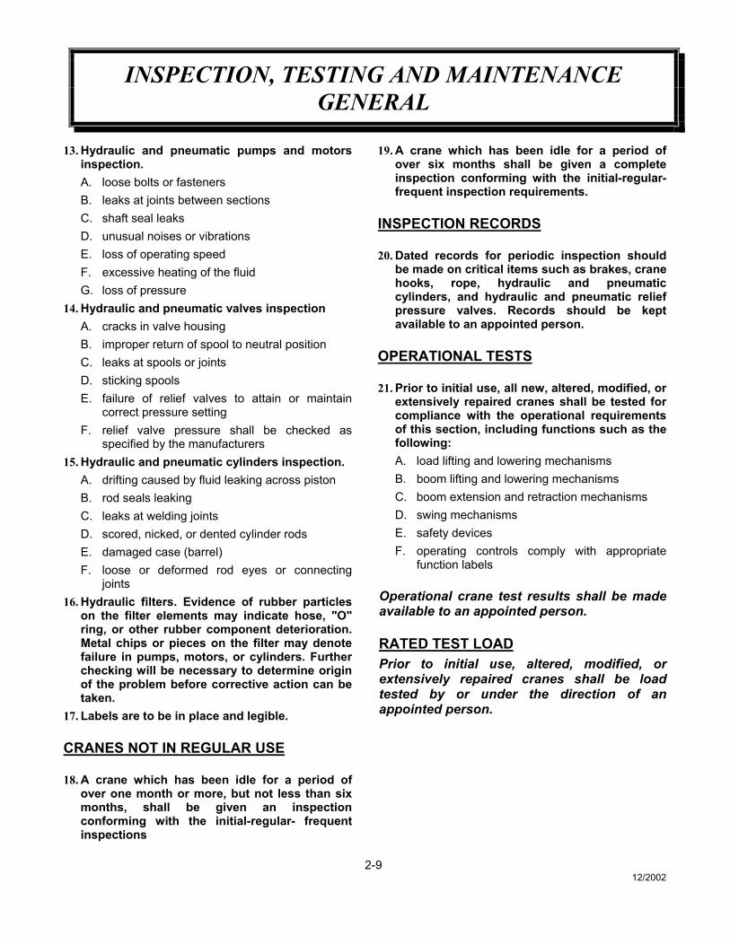
13. Hydraulic and pneumatic pumps and motorsinspection.A. loose bolts or fastenersB. leaks at joints between sectionsC. shaft seal leaksD. unusual noises or vibrationsE. loss of operating speedF. excessive heating of the fluidG. loss of pressure
14. Hydraulic and pneumatic valves inspectionA. cracks in valve housingB. improper return of spool to neutral positionC. leaks at spools or jointsD. sticking spoolsE. failure of relief valves to attain or maintain
correct pressure settingF. relief valve pressure shall be checked as
specified by the manufacturers15. Hydraulic and pneumatic cylinders inspection.
A. drifting caused by fluid leaking across pistonB. rod seals leakingC. leaks at welding jointsD. scored, nicked, or dented cylinder rodsE. damaged case (barrel)F. loose or deformed rod eyes or connecting
joints16. Hydraulic filters. Evidence of rubber particles
on the filter elements may indicate hose, "O"ring, or other rubber component deterioration.Metal chips or pieces on the filter may denotefailure in pumps, motors, or cylinders. Furtherchecking will be necessary to determine originof the problem before corrective action can betaken.
17. Labels are to be in place and legible.
CRANES NOT IN REGULAR USE
18. A crane which has been idle for a period ofover one month or more, but not less than sixmonths, shall be given an inspectionconforming with the initial-regular- frequentinspections
19. A crane which has been idle for a period ofover six months shall be given a completeinspection conforming with the initial-regular-frequent inspection requirements.
INSPECTION RECORDS
20. Dated records for periodic inspection shouldbe made on critical items such as brakes, cranehooks, rope, hydraulic and pneumaticcylinders, and hydraulic and pneumatic reliefpressure valves. Records should be keptavailable to an appointed person.
OPERATIONAL TESTS
21. Prior to initial use, all new, altered, modified, orextensively repaired cranes shall be tested forcompliance with the operational requirementsof this section, including functions such as thefollowing:A. load lifting and lowering mechanismsB. boom lifting and lowering mechanismsC. boom extension and retraction mechanismsD. swing mechanismsE. safety devicesF. operating controls comply with appropriate
function labels
Operational crane test results shall be madeavailable to an appointed person.
RATED TEST LOADPrior to initial use, altered, modified, orextensively repaired cranes shall be loadtested by or under the direction of anappointed person.
2-912/2002

INSPECTION, TESTING AND MAINTENANCEGENERAL
22. Test loads shall not exceed 110% of themanufacturer's load ratings.
23. Written reports shall be maintained showingtest procedures and confirming the adequacyof repairs.
MAINTENANCE
PREVENTIVE MAINTENANCE
24. Before adjustment and repairs are started on acrane, the following precautions shall be takenas applicable:A. crane placed where it will cause the least
interference with other equipment oroperations
B. all controls at the "off" positionC. starting means rendered inoperativeD. boom lowered to the ground if possible or
otherwise secured against droppingE. relieve hydraulic oil pressure from all hydraulic
circuits before loosening or removing hydrauliccomponents
25. Warning or "OUT OF ORDER" signs shall beplaced on the crane controls.
26. After adjustments and repairs have been made,the crane shall not be returned to service untilall guards have been reinstalled, trapped airremoved from hydraulic system (if required),safety devices reactivated, and maintenanceequipment removed.
ADJUSTMENTS AND REPAIRS
27. Any hazardous conditions disclosed by theinspection requirements shall be correctedbefore operation of crane is resumed,Adjustments and repairs shall be done only bydesignated personnel.
28. Adjustments shall be maintained to assurecorrect functioning of components, Thefollowing are examples:A. functional operating mechanismB. safety devicesC. control systems
29. Repairs or replacements shall be provided asneeded for operation.The following are examples:A. critical parts of functional operating
mechanisms which are cracked, broken,corroded, bent, or excessively worn
B. critical parts of the crane structure which arecracked, bent, broken, or excessively corroded
C. crane hooks showing cracks, damage, orcorrosion shall be taken out of service. Repairsby welding are not recommended
30. Instructions shall be provided by themanufacturer for the removal of air fromhydraulic circuits.
LUBRICATION
All moving parts of the crane, for whichlubrication is specified, should be regularlylubricated per the manufacturer'srecommendations and procedures.
ROPE INSPECTION
31. Frequent InspectionA. All running ropes in service should be visually
inspected once each working day. A visualinspection shall consist of observation of allrope which can be in use during the daysoperations. These visual observations shouldbe considered with discovering gross damagesuch as listed below, which may be animmediate hazard.1. distortion of the rope such as kinking,
crushing, un-stranding, birdcaging, mainstrand displacement, or core protrusion.Loss of rope diameter in a short length orunevenness of outer strands should bereplaced
2. general corrosion3. broken or cut strands;4. number, distribution and type of visible
broken wires. When such damage isdiscovered, the rope shall either beremoved from service or given asinspection.
2-1012/2002

INSPECTION, TESTING AND MAINTENANCEGENERAL
B. Care shall be taken when inspecting sectionsof rapid deterioration such as flange points,crossover points, and repetitive pickup pointson drums.
32. Periodic inspectionA. The inspection frequency shall be determined
by a qualified person and shall be based onsuch factors as1. expected rope life as determined by
experience on the particular installation orsimilar installations
2. severity of environment3. percentage of capacity lifts4. frequency rates of operation5. exposure to shock loads
Inspection need not be at equal calendarintervals and should be more frequent as therope approaches the end of it's service life.This inspection shall be made at leastannually.
B. Periodic inspection shall be performed by adesignated person. This inspection shall coverthe entire length of the rope. Only the surfacewires need be inspected. No attempt should bemade to open the rope. Any deteriorationresults in appreciable loss of original strength,such as described below, shall be noted anddetermination made as to whether use of therope would constitute a hazard: points listedabove reduction of rope diameter belownominal diameter due to loss of core support,internal or external corrosion, or wear ofoutside wires; severely corroded, cracked,bent, worn or improperly applied connections;
C. Care shall be taken when inspecting sectionssubject to rapid deterioration such as thefollowing:1. sections in contact with saddles, equalizer
sheaves, or other sheaves where ropetravel is limited
2. sections of the rope at or near terminalends where corroded or broken wires mayprotrude
ROPE REPLACEMENT
33. No precise rules can be given for determinationof the exact time for replacement of rope, sincemany variable factors are involved.
Continued use in this respect depends upon goodjudgement by a designated person in evaluatingremaining strength in a used rope after allowancefor deterioration disclosed by inspection.Continued rope operation depends upon thisremaining strength.
34. Conditions such as the following shall bereason for questioning continued use of therope or increasing the frequency of inspection:A. in running ropes, six randomly distributed
broken wires in one lay or three broken wiresin one strand in one lay
B. one outer wire broken at the contact point withthe core of the rope structure and protrudes orloops out of the rope structure. Additionalinspection of this section is required
C. wear of one third of the original diameter of theoutside individual wire
D. kinking, crushing, birdcaging, or any otherdamage resulting in distortion of the ropestructure
E. evidence of any heat damage from any causeF. reduction from nominal diameter of more than
1/64 in. (0.4mm) for diameters up to andincluding 5/16 in. (8 mm), 1/32 in. (0.8 mm) fordiameter 3/8 in. (9.5 mm) to and including 1/2in. (13 mm), 3/64 in. (1.2 mm) for diameter9/16 in. (14.5 mm) to and including 3/4 in. (19mm). 1/16 in. (1.6 mm) for diameter 7/8 in. (22mm) to and including 11/8 in. (29 mm), 3/32 in.(2.4 mm) for diameters 11/4 in. (32 mm) to andincluding 11/2 in. (38 mm)
G. In standing ropes, more than two broken wiresin one lay in sections beyond end connectionsor more than one broken wire at an endconnection.
2-1112/2002
INSPECTION, TESTING AND MAINTENANCEGENERAL
H. Replacement rope shall have a strength ratingat least as great as the original rope furnishedor recommended by the crane manufacturer.Any deviation from the original size, grade, orconstruction shall be specified by a ropemanufacturer, or a qualified person.
35. Rope not in regular use: all rope which hasbeen idle for a period of a month or more dueto shutdown or storage of a crane on which it isinstalled, shall be given and inspection inaccordance with above information before it isplaced in service. This inspection shall be forall types of deterioration and shall beperformed by a qualified person.
36. Inspection recordsA. A. frequent inspection- no records
requiredB. A. periodic inspections- in order to
establish data as a basis for judging theproper time for replacement, a dated reportcondition at each periodic inspectionshould be kept on file. This report shallcover points of deterioration listed above.
ROPE MAINTENANCE
37. Rope should be stored to prevent damage ordeterioration.
38. Unreeling or uncoiling of rope shall be done asrecommended by the rope manufacturer andwith care to avoid kinking or inducing twist.
39. Before cutting a rope, seizing shall be placedon each side of the place where the rope is to
be cut to prevent unlaying of the strands. Onpre-formed rope, one seizing on each side ofthe cut is required. On non-preformed ropes of7/8 in. (22 mm) diameter or smaller, twoseizings on each side of the cut are required,and for non-preformed rope 1 in. (25 mm)diameter or larger, three seizings on each sideof the cut are required.
40. During installation care should be exercised toavoid dragging of the rope in the dirt or aroundobjects which will scrape, nick crush or inducesharp bends in it.
41. Rope should be maintained in a well-lubricatedcondition. It is important that lubricant appliedas a part of a maintenance program shall becompatible with the original lubricant and tothis end the rope manufacturer should beconsulted. Lubricant applied shall be the typewhich does not hinder visual inspection. Thosesections of rope which are located oversheaves or otherwise hidden during inspectionand maintenance procedures require specialattention when lubricating rope. The object ofrope lubrication is to reduce internal frictionand to prevent corrosion.
42. When an operating rope shows greater wear orwell defined localized areas than on theremainder of the rope, rope life can beextended in cases where a section at the wornend, and thus shifting the wear to differentareas of the rope.
2-1212/2002

MAINTENANCE OF BATTERIES
2-139/98
Maintenance of Auto Crane unit batteries differs verylittle from the generally prescribed maintenance of anylead acid battery. All batteries must be kept properlycharged, properly filled with water, and relatively clean.
Keep Properly Charged
Many things affect the proper charge to a battery, suchas:
1 Regulator settings
2 Proper tightness of belts on the alternatoror generator
3 Good, clean connections of all cablesand wires at the following places:A. BatteryB. RegulatorC. Starting motorD. Alternator or generatorE. Ground connections (most important)
It is of extreme importance to keep the battery as fullycharged as possible without overcharging, especiallywhen vehicles are left outside for extended periods inextremely cold climates. A battery can freeze. Freezingpoints for various specific gravities of acid are asfollows:
Specific Gravity Freezing Temp.(Corrected to 80ºF) Degrees F.
1.280 -90ºF 1.250 -62ºF 1.200 -16ºF 1.150 5ºF 1.100 19ºF
As shown, a half-charged battery (about 1.200 specificgravity) cannot stand for any length of time at 20ºF or itwill freeze.
The main reason for keeping the battery as fully chargedas possible without over-charging is to ensure that poweris available even though the vehicle has been standingfor some time.
Keep Properly Filled with Water
The battery should always be properly filled with water.If the electrolyte level is allowed to fall below the top ofthe plates, the results become threefold:
1 The exposed portion of the plate will becomesulfated.
2 The portion of the plate exposed is not usable.
3 That portion of the acid remaining becomes moreconcentrated and may cause more rapid deteriorationof the remaining parts of the battery.
Keep A Relatively Clean Battery
The battery should be kept clean. Batteries filled withacid and which are not in use self-discharge to a limiteddegree because of the nature of the materials within thebattery. If dirt is allowed to collect on the top of thebattery (and this dirt absorbs moisture) and electrical pathcan be set up between the various terminals of the batteryand the ground. Once such a path has been established,the self-discharge of the battery is accelerated. This alsoaccelerates corrosion of the battery cables at theterminals.
Periodic Maintenance is Needed
A definite program of periodic maintenance of allbatteries should be conducted on a regular basis. Periodicmaintenance includes:
1 Checking belts for tightness on the chargingequipment
2 Checking battery electrolyte levels
3 Checking cables for good connections
4 Cleaning where corrosion is apparent
When corrosion is cleaned off, the cable terminals andbattery terminals should be coated with a light coating ofpetroleum jelly before they are replaced. When terminalsare cleaned, the top of the battery should be cleaned witha mild solution of soda water.

MAINTENANCE OF BATTERIES
2-149/98
Low Maintenance Batteries(Maintenance Free)
Low maintenance batteries should not be used onAuto Cranes or trucks equipped with Auto Cranes.The batteries are not designed for "deep" discharge.
Testing Your Battery
If the condition of the battery is in question, it should beremoved from the vehicle, taken to the shop, andallowed to reach room temperature. It should then berecharged until specific gravity readings taken at one-half hour intervals. If the specific gravity readings arefairly uniform, the battery should be checked with a highrate tester. Use the tester in accordance with themanufacturer's instructions. The high rate tester is thebest method to test a questionable battery.
If, after charging, it is noted that the specific gravityreading of one cell is 30 points less than any of the othercells, it may be assumed that the cell is bad and that thebattery should be replaced. If all cells are uniform butnot up to full charge, a low rate of charge should beattempted for an extended time. This usually willrecover a badly sulfated battery.
Replacing a Battery
If it is necessary to replace a battery, and a dry chargebattery is used, the following procedure applies:
1 Fill the battery with electrolyte of the proper specificgravity.
2 Place the battery on charge according to themanufacturer's instructions.
It is essential that the second step above be followed toensure that the battery going on the vehicle is fullycharged.
It is also very important that the battery hold-downs bechecked periodically to ensure that the batteries areproperly positioned to avoid vibration problems, breakageof cables or terminals. Care must be taken to avoidcracking or breaking containers or covers by tighteninghold-down fixtures excessively. They also must not be soloose that breakage results from a hold-down that is tooloose.

SAFETY DECAL SECTION2003 SERIES
3-16/26/2003
PART NO.: 40579000DECAL: OPERATING INSTRUCTIONSFUNCTION: To inform the operator of the proper
procedure to follow for safe operation of the crane.
USED ON: All CranesQUANTITY: 1PLACEMENT: Right side plate
PART NO.: 040529000 USED ON: Articulated & Stiff Boom CranesDECAL: ELECTROCUTION HAZARD QUANTITY: 2FUNCTION: To inform the operator of the
hazard involved with contacting electrical power lines with crane boom.
PLACEMENT: Both sides of end of lower boom

SAFETY DECAL SECTION2003 SERIES
3-26/26/2003
PART NO.: 040517000DECAL: STAY CLEAR OF BOOMFUNCTION: To inform the operator of the
hazard of proximity or contact with the crane boom during operation.
USED ON: All CranesQUANTITY: 2PLACEMENT: Both sides of crown
PART NO.: 040518000 USED ON: All cranes.DECAL: STAY SLEAR OF LOAD QUANTITY: 2FUNCTION: To inform the operator of the hazard of
proximity or contact with the crane load during operation.
PLACEMENT: Both sides of the down haul weight
AT ALL TIMESP/N 040518
PART NO.: 040519000 USED ON: All cranes.DECAL: SCISSORS POINT QUANTITY: 1FUNCTION: To inform the operator of possible
danger at scissors point on crane.PLACEMENT: Both sides of the lift cylinder

DECAL LAYOUTP/N: 600048 – 9’ BOOM
3-37/7/2003
9
8
2
30
SERIAL NUMBER
5
3
6
20
4
1 10
SERIAL NUMBER
7
7
10 16
.18
ITEM NO. QTY. PART NO. DESCRIPTION1 2 040517 DECAL STAY CLEAR2 1 600006 DECAL LOAD CHART 9" BOOM3 1 330967 DECAL 20034 1 320318 DECAL ANGLE INDICATOR5 1 040579 DECAL WORK RULES6 2 040518 DECAL STAY CLEAR7 2 600047 DECAL AUTO CRANE8 1 040619 DECAL A/C LOGO9 1 040519 DECAL SCISSIRS POINT
10 2 040529 DECAL DANGER ELECT
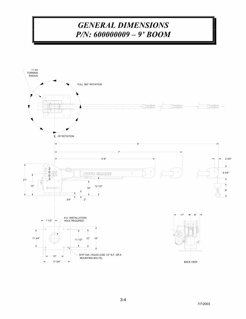
GENERAL DIMENSIONSP/N: 600000009 – 9’ BOOM
3-47/7/2003
MOUNTING BOLTS)9/16" DIA. HOLES (USE 1/2" N.F. GR 8
17 3/4"
11 3/4"
12"
7 1/2"
11 1/2" 12"
8 in. INSTALLATIONHOLE REQUIRED
15"
BACK VIEW
11" 6"
12 1/2"
FULL 360° ROTATION
14"
21"
3/4" 2"
10"
CL OF ROTATION
11 3/4TURNING
RADIUS
5'-6"
7'
9'
9"
6 3/4"
2 3/4"
02
03

MOUNTING AND INSTALLATION2003 SERIES
3-57/7/2003
DRILL 13/16THRU FLOOR
NUT
NO. BB-50 INSULATORBUSHING ON CABLEASSEMBLY
POSITIVE POLESTARTERSOLENOID
STARTER
BATTERY CABLEFROM CRANE
GROUND FROM MOTORTO CHASSIS FRAMECHASSIS
FRAME
BATTERY CABLE
03
02
FOR OVER THE ROAD USE.MAKE SURE HOIST ANCHOR IS USED
INSTALLATION-BATTERY CABLE
1. Drill 13/16” hole in floor. Installation bushing, which is connected to cable, so it fits holesnug.
2. Run cable to positive battery terminal. Connect black cable to negative batteryterminal or suitable chassis ground point. Locate cables so that they will be protected.Avoid sharp edges. Use the No. 083800 frame clips provided to hold cables securelyin place.
3. If the battery is grounded to the engine it may be necessary to add an additionalground cable from the engine to the chassis frame to obtain maximum power at crane.

OPERATING INSTRUCTUIONS2003 SERIES
3-67/7/2003
To Extend:Turn Brake Handle (1) counterclock-wise to release brake andturn boom to a convenientlocation for extending boom.Tighten Brake by turning BrakeHandle clock-wise. Use pendantcontrol to let out more cable forboom extension. Remove BoomExtension Pin (2) in Lower Boom(3). Slide Upper Boom out ofLower Boom until a new set of pinholes in Upper Boom appear inpin hole in Lower Boom. ReplacePin in Lower Boom.
Boom is now ready to raise.
To Raise:Use pendant control to let outmore cable for boom elevation.Remove Hitch Clip from BoomElevation Pin (4) in BoomHousing (5). Place hand onLower Boom Handle (6) andgently pull down on handle. PullBoom Elevation Pin out of Boomand Boom Housing. Raise Boomto desired elevation. Align tube inBoom with holes in Housing andreplace Boom Elevation Pin.Replace Hitch Clip on BoomElevation Pin.
The crane is now ready to lift theload.
6
23
5
4
1
5
4
3
00
2
1 62
3
CAUTION:DO NOT STAND DIRECTLY UNDER BOOM WHEN RAISING OR LOWERINGBOOM OR SERIOUS INJURY MAY RESULT.
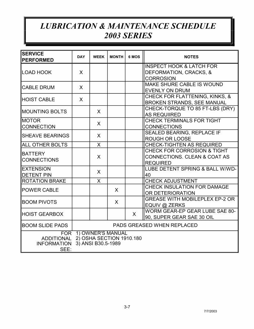
LUBRICATION & MAINTENANCE SCHEDULE2003 SERIES
3-77/7/2003
SERVICE PERFORMED
DAY WEEK MONTH 6 MOS NOTES
LOAD HOOK XINSPECT HOOK & LATCH FOR DEFORMATION, CRACKS, & CORROSION
CABLE DRUM X MAKE SHURE CABLE IS WOUND EVENLY ON DRUM
HOIST CABLE X CHECK FOR FLATTENING, KINKS, & BROKEN STRANDS, SEE MANUAL
MOUNTING BOLTS X CHECK-TORQUE TO 85 FT-LBS (DRY) AS REQUIIRED
MOTOR CONNECTION X CHECK TERMINALS FOR TIGHT
CONNECTIONS
SHEAVE BEARINGS X SEALED BEARING, REPLACE IF ROUGH OR LOOSE
ALL OTHER BOLTS X CHECK-TIGHTEN AS REQUIRED
BATTERY CONNECTIONS X
CHECK FOR CORROSION & TIGHT CONNECTIONS. CLEAN & COAT AS REQUIRED
EXTENSION DETENT PIN X LUBE DETENT SPRING & BALL W/WD-
40ROTATION BRAKE X CHECK ADJUSTMENT
POWER CABLE X CHECK INSULATION FOR DAMAGE OR DETERIORATION
BOOM PIVOTS X GREASE WITH MOBILEPLEX EP-2 OR EQUIV @ ZERKS
HOIST GEARBOX X WORM GEAR-EP GEAR LUBE SAE 80-90, SUPER GEAR SAE 30 OIL
BOOM SLIDE PADSFOR
ADDITIONAL INFORMATION
SEE:
PADS GREASED WHEN REPLACED 1) OWNER'S MANUAL 2) OSHA SECTION 1910.180 3) ANSI B30.5-1989

LUBRICATION & MAINTENANCE SCHEDULE2003 SERIES
3-87/7/2003
CAUTION: Routine maintenance insures trouble-free operation and protectsyour investment. All warranties are void if maintenance is neglected.
NOTES:1. Use only authorized parts. Any damage or malfunction caused by the use of
unauthorized parts is not covered by Warranty or Product Liability2. Once a bolt has been torqued to its rated capacity and then removed; the bolt
should be replaced with a new one.3. Auto Crane Company recommends that this crane be serviced per “Crane
Inspection Log” P/N 999978. These logs should be filled in at the intervals notedand kept as a permanent record. Additional copies are available from your localdistributor.
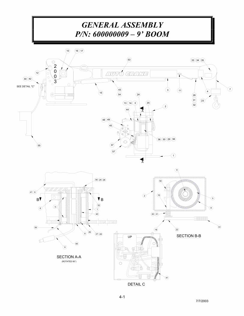
GENERAL ASSEMBLYP/N: 600000009 – 9’ BOOM
4-17/7/2003
37
353433
15
42
231413
45
44
74
28
31
32
11
10 16
12
3
36 30
A
A
23
1
43
55
17
25
49
54
48
30
29
002
3
56
SEE DETAIL "C"
24
57
53
26
SECTION A-A(ROTATED 90°)
9
9 2827
8
B
41 6
5
40
1
52
B
29 2856
SECTION B-B
DETAIL C
41
UP
2120
2 19
9
50
8
5
18 225159
60
GENERAL ASSEMBLYP/N: 600000009 – 9’ BOOM
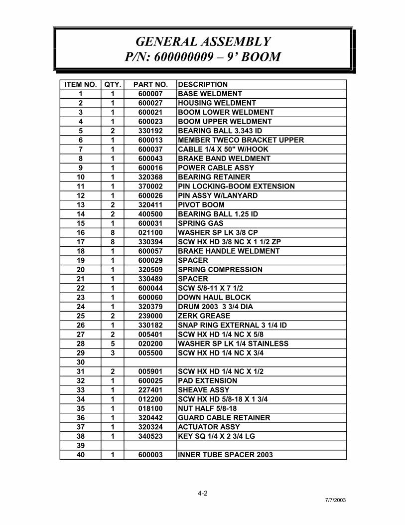
4-27/7/2003
ITEM NO. QTY. PART NO. DESCRIPTION1 1 600007 BASE WELDMENT2 1 600027 HOUSING WELDMENT3 1 600021 BOOM LOWER WELDMENT4 1 600023 BOOM UPPER WELDMENT5 2 330192 BEARING BALL 3.343 ID6 1 600013 MEMBER TWECO BRACKET UPPER7 1 600037 CABLE 1/4 X 50" W/HOOK8 1 600043 BRAKE BAND WELDMENT9 1 600016 POWER CABLE ASSY
10 1 320368 BEARING RETAINER11 1 370002 PIN LOCKING-BOOM EXTENSION12 1 600026 PIN ASSY W/LANYARD13 2 320411 PIVOT BOOM14 2 400500 BEARING BALL 1.25 ID15 1 600031 SPRING GAS16 8 021100 WASHER SP LK 3/8 CP17 8 330394 SCW HX HD 3/8 NC X 1 1/2 ZP18 1 600057 BRAKE HANDLE WELDMENT19 1 600029 SPACER20 1 320509 SPRING COMPRESSION21 1 330489 SPACER22 1 600044 SCW 5/8-11 X 7 1/223 1 600060 DOWN HAUL BLOCK24 1 320379 DRUM 2003 3 3/4 DIA25 2 239000 ZERK GREASE26 1 330182 SNAP RING EXTERNAL 3 1/4 ID27 2 005401 SCW HX HD 1/4 NC X 5/828 5 020200 WASHER SP LK 1/4 STAINLESS29 3 005500 SCW HX HD 1/4 NC X 3/43031 2 005901 SCW HX HD 1/4 NC X 1/232 1 600025 PAD EXTENSION33 1 227401 SHEAVE ASSY34 1 012200 SCW HX HD 5/8-18 X 1 3/435 1 018100 NUT HALF 5/8-1836 1 320442 GUARD CABLE RETAINER37 1 320324 ACTUATOR ASSY38 1 340523 KEY SQ 1/4 X 2 3/4 LG3940 1 600003 INNER TUBE SPACER 2003

NOTES

GENERAL ASSEMBLYP/N: 600000009 – 9’ BOOM
4-37/7/2003
ITEM NO. QTY. PART NO. DESCRIPTION41 1 600078 TWECO-MALE POWER CONDUCTOR42 1 600099 RELAY ASSY43 2 600077 GAS SPRING PIN44 1 600034 BRACKET ACTUATOR45 1 600039 GROMMET WIRE GUIDE46 1 600073 SHIP KIT NEW 2003 CRANE4748 4 007807 SCW HX HD 5/16-18 X 3/449 4 020600 WASHER 5/1650 1 018201 NUT 5/8-1151 1 600058 HANDLE GRIP52 1 023700 ROLL PIN 1/8 DIA53 1 600048 DECAL LAYOUT54 2 366813 PIN HITCH CLIP55 1 330519 PENDANT56 2 020300 WASHER FL 1/457 3 270326 INSULATOR BOOT BLACK58 1 634401 TIE CABLE-MEDIUM
HOIST ACTUATOR ASSEMBLYP/N: 160269 - 2003 SERIES
7-16/18/2003
22
42
10
32
1460
219
61
5 38 65 31
30
37
59
35
45
155
2313
25
51
27
638
26
44
3 51 28
12
48
34
9
49
64
46
1156 42 25
5233
167
6224
4354
4
6654
62
2462
207
6
5047
3936
58
40
29
2118
5747
4153
17

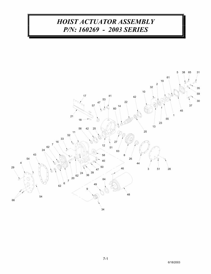
HOIST ACTUATOR ASSEMBLYP/N: 160269 - 2003 SERIES
7-26/18/2003
ITEM NO. QTY. PART NO. DESCRIPTION1 1 360637 FLAT SPRING2 1 360331 CAM PLATE3 1 300041 GEAR HOUSING COVER4 1 300042 SPUR GEAR HOUSING COVER5 1 360450 BRAKE COVER6 1 300043 IDLER GEAR7 2 300044 SPUR GEAR8 1 300045 WORM R.H. GEAR9 1 300046 PINION GEAR
10 1 360336 BRAKE HOUSING11 1 300047 SPUR GEAR HOUSING12 1 300048 GEAR HOUSING COVER13 1 360339 BRAKE HUB14 1 300049 KEY 3/16 SQ X 1/2 LG15 N/A 16 1 300050 KEY 3/16 SQ X 1 9/16 LG17 1 341561 KEY 1/4 SQ X 2 3/4 LG18 2 300052 KEY RD 5/16 X 5/16 X 15/16 LG19 1 360342 RETAINER PLATE20 1 300053 SPUR GEAR SHAFT21 1 320323 OUTPUT SHAFT22 1 320312 RIGHT HAND WORM GEAR23 2 360345 BALL24 3 300056 NEEDLE BEARING25 2 300057 BALL BEARING26 1 300058 BUSHING27 1 300059 BUSHING28 10 320313 SCW HX HD 1/4 NC X 3/4 LG NYLOCK29 12 005500 SCW HX HD 1/4 NC X 3/4 LG 30 4 005604 SCW HX HD 1/4 NC X 1 LG31 1 320311 SCW HX HD 3/8 NC X 1 1/2 LG ALL THD32 4 320310 SCW HX HD 1/4 NC X 1 LG33 4 300060 SCW HX HD 1/4 NC X 3/4 LG LOC-WEL34 1 300061 SCW HX HD 1/4 NC X 5/16 LG LOC-WEL35 1 360353 NUT HX JAM 3/8 NC36 3 071012 NUT HX 3/8 NF37 4 360354 WASHER SP LK 1/4 MED SECT38 2 360455 WASHER FL 1/4 ALUM39 3 021100 WASHER SP LK 3/840 1 320314 ELL 90 DEG 3/8-18 NPT BOTH ENDS

NOTES

HOIST ACTUATOR ASSEMBLYP/N: 160269 - 2003 SERIES
7-36/18/2003
ITEM NO. QTY. PART NO. DESCRIPTION41 1 320315 ELL 90 DEG 1/4-18 NOT BOTHE ENDS42 2 300062 GASKET BEARING43 1 300063 SPUR GEAR HOUSING GASKET44 1 300064 GEAR HOUSING COVER GASKET45 1 360359 BRAKE COVER GASKET46 1 300065 WOODRUFF KEY47 2 300066 RELIEF FITTING48 1 300067 12V MOTOR49 1 300068 O-RING 1 OD X 1/8 THK50 1 300069 REDUCER -6 NPT/-2 NPT51 2 300070 PLUG PIPE -4 NPT SQ HD52 1 300073 PLUG PIPE -6 NPT HX SOC HEADLESS53 1 300074 REDUCER -4 NPT/-2 NPT54 2 300075 DOWEL PIN55 2 360364 THRUST PLATE56 1 300076 OIL SEAL 3/4 ID X 1 1/4 OD X 1/4 THK57 1 300077 OIL SEAL 1 1/4 ID X 1 3/4 OD X 1/4 THK58 1 300078 OIL SEAL 1 1/2 ID X 2 1/4 OD X 5/16 THK59 1 360371 THREAD SEAL60 1 300079 SNAP RING61 1 360368 SPRING62 3 300080 THRUST WASHER63 1 300081 THRUST WASHER64 1 300082 FIBER WASHER65 2 360456 SCW 1/4 NC X 1 LG ALL THD66 2 320382 PIPE PLUG
AUTOMATIC SAFETY BRAKE ASSEMBLY(OIL COOLED) HOIST - 2003 SERIES
7-46/19/2003
10 8
13
3
1
616
4
5
72
9
15
11
12
148
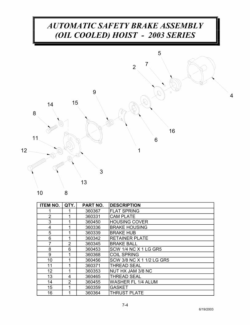
ITEM NO. QTY. PART NO. DESCRIPTION1 1 360367 FLAT SPRING2 1 360331 CAM PLATE3 1 360450 HOUSING COVER 4 1 360336 BRAKE HOUSING5 1 360339 BRAKE HUB6 1 360342 RETAINER PLATE7 2 360345 BRAKE BALL8 6 360453 SCW 1/4 NC X 1 LG GR59 1 360368 COIL SPRING
10 1 360456 SCW 3/8 NC X 1 1/2 LG GR511 1 360371 THREAD SEAL12 1 360353 NUT HX JAM 3/8 NC13 4 360465 THREAD SEAL14 2 360455 WASHER FL 1/4 ALUM15 1 360359 GASKET16 1 360364 THRUST PLATE

AUTOMATIC SAFETY BRAKE ASSEMBLY(OIL COOLED) HOIST - 2003 SERIES
7-56/19/2003
ASSEMBLY INSTRUCTIONS: 1. Winch has right hand worm and gear. Cable spools over drum.
Use number one slots for brake balls (7) in cam plate (2). 2. Install brake hub (5) through brake housing (4) on winch worm
with key. 3. Assemble balls (7) in cam plate (2) using hard grease to hold
balls in place. 4. Place cam plate (2) on brake hub (5), matching its holes with
the balls. 5. Install thrust plate (16). 6. Thread capscrew (10) with jam nut (12) and thread seal (11)
through housing cover (3). 7. Place gasket (15) on housing cover (3). 8. Install coil spring (9) on capscrew (10). 9. Install flat spring (1) on capscrew (10). 10. Secure retainer plate (6) and flat spring(1) to housing cover(3)
using capscrews (8) and washers (14). 11. Using capscrews (8) and thread seals (13) attach housing
cover (3) to brake housing (4). 12. Test brake by shifting winch to UP then DOWN to see if brake
is working in proper rotation. If not, remove housing cover (3)and locate brake balls (7) in opposite set of slots of camplate (2).
13. Adjust to suit by tightening or loosening capscrew (10) onoutside of housing cover (3). When proper adjustment isobtained, secure capscrew (10) with jam nut (12).

WIRING DIAGRAM2003 SERIES
8-17/8/2003
UP5
1
4
5
9 6 8GREEN BLACK
712 WHITE
2
RIA
SCHEMATIC
R2B
R2L
R2A
PENDANT
RIL
RIB
TWECO 12 VDC
HOISTA1 F1
UP
F2
DOWNHOIST
A2
3
ITEM NO. QTY. PART NO. DESCRIPTION1 1 330519 HOIST CONTROL PENDANT2 1 330517 FEMALE SOCKET3 1 600016 POWER CABLE ASSEMBLY4 1 622323 CONDUCTOR 6 GA 600V BLACK X 26"5 2 622327 CONDUCTOR 6 GA 600V BLACK X 28"6 1 600061 CONDUCTOR 16 GA ST GREEN X 2 3/4"7 1 600062 CONDUCTOR 16 GA ST WHITE X 2 3/4"8 1 600063 CONDUCTOR 16 GA ST BLACK X 1 1/4"9 2 330033 12V RELAY

POWER CABLE ASSEMBLYP/N: 600016
8-22/98
3
2
6
1
7 8
SIDE PLATES
OUTER TUBE
BASE PLATE
4
5
5
*
*
*
9*10
*
11
ITEM NO. QTY. PART NO. DESCRIPTION1 1 669200 FEMALE TWECO CONNECTOR2 1 600015 TWECO BRACKET3 1 330258 TWECO POWER CONNECTOR4 1 002900 SCW SOC HD 1/4 NC X 3/8 GR85 2 669300 MALE TWECO CONNECTOR6 1 341219 CONDUCTOR 600V X 29"7 1 005500 SCW HX HD 1/4 NC X 3/48 1 020300 WASHER FL 1/4 CP9 1 600015 LOWER TWECO BRACKET
10 2 005401 SCW HX HD 1/4 NC X 5/811 2 020200 WASHER SP LK 1/4

PENDANT ASSEMBLYP/N: 330519
8-36/19/2003
1
2
3
4
5
3
3
6
3
3 7
8
GREEN
WHITEBLACK
ITEM NO. QTY. PART NO. DESCRIPTION1 1 675271 NUT HX2 1 675281 WASHER TANG3 1 675206 HOUSING KIT4 1 675202 SWITCH W/SEAL NUT5 1 675201 HOUSING 6 1 675261 SEAL7 1 675291 CABLE PENDANT8 1 330518 FEMALE PLUG
TROUBLESHOOTING2003 SERIES
PROBLEM CAUSE/SOLUTION
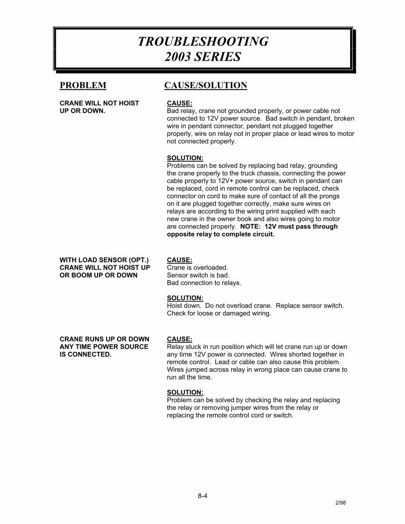
CRANE WILL NOT HOISTUP OR DOWN.
CAUSE:Bad relay, crane not grounded properly, or power cable notconnected to 12V power source. Bad switch in pendant, brokenwire in pendant connector, pendant not plugged togetherproperly, wire on relay not in proper place or lead wires to motornot connected properly.
SOLUTION:Problems can be solved by replacing bad relay, groundingthe crane properly to the truck chassis, connecting the powercable properly to 12V+ power source, switch in pendant canbe replaced, cord in remote control can be replaced, checkconnector on cord to make sure of contact of all the prongson it are plugged together correctly, make sure wires onrelays are according to the wiring print supplied with eachnew crane in the owner book and also wires going to motorare connected properly. NOTE: 12V must pass throughopposite relay to complete circuit.
WITH LOAD SENSOR (OPT.)CRANE WILL NOT HOIST UPOR BOOM UP OR DOWN
CAUSE:Crane is overloaded.Sensor switch is bad.Bad connection to relays.
SOLUTION:Hoist down. Do not overload crane. Replace sensor switch.Check for loose or damaged wiring.
CRANE RUNS UP OR DOWNANY TIME POWER SOURCEIS CONNECTED.
CAUSE:Relay stuck in run position which will let crane run up or downany time 12V power is connected. Wires shorted together inremote control. Lead or cable can also cause this problem.Wires jumped across relay in wrong place can cause crane torun all the time.
SOLUTION:Problem can be solved by checking the relay and replacingthe relay or removing jumper wires from the relay orreplacing the remote control cord or switch.
8-42/98

TROUBLESHOOTING2003 SERIES
HOW TO CHECK RELAY:Our relays are normally closed across thebottom posts (C & D). When activated, theywill open across (C & D) and close across A& B). To activate these relays, use 12Vpositive and 12V negative wires and placethem on posts (F & E). You may place 12V+on post F or E as long as you place 12V onthe remaining post (F & E) using an ohmmeter or test light. Check across posts (A &B). You should get an ohm reading or yourtest light should be on when you have therelay activated. With the relay still activated,check across posts (C & D). You shouldhave no ohm reading or test light at this pointwith relay activated. (At this point, disconnect12V+ and 12V– from posts (F & E).
This should let relay return to its normalposition. Using your ohm meter or test lightagain, check the relay across posts (A & B).If relay is working correctly, you should haveno reading at all. Then check across posts(C & D). You should have an ohm reading ortest light should be on. If you get the aboveresults, relay is okay. If you get any variationin the above explanation on the relay you arechecking, check the relay again. If it stillshows a difference, the relay is bad andshould be replaced. NOTE: The aboveexplanation is with relays completelydisconnected from all wires on motorcircuits and ground wires. These circuitscan give you false readings sometimes.
A BF
C D
E
8-52/98

LOAD CHARTP/N: 600006
10-17/8/2003
CAPACITY IN POUNDSHORIZONTAL REACH IN FT
685#
1160#
945#
1285#
1330#
1565#
2000#
2000# 10'
9'
8'
7'
6'
5'
4'
3'
2'
1'
0
9'8'7'6'5'4'3'2'1'0
30°
45°
60°
75°
15°
1125# 665#
770#2000#

P.O. Box 580697 * Tulsa, OK 74158-0697
4707 N. Mingo Rd. * Phone (918) 836-0463
LIMITED WARRANTY 2 YEAR PARTS AND LABOR
Auto Crane will warranty to the consumer for a period of (2) years parts and labor from the date of purchase. Each new Auto Crane unit they sell will be free under normal use and service from defects in material and workmanship. Date of purchase will be honored as the date indicated on the Bill of Sale, which must accompany the Warranty Registration and be on file with Auto Crane. Absent a valid Warranty Registration and appropriate documentation, the original date of manufacture, as indicated by the serial number on the product, will be used to determine the effective date of the 2 year warranty. The obligation of Auto Crane under this warranty is limited to the replacement or repair of parts that appear to the manufacturer after review and/or inspection to be defective and paid flat rate labor for replacing defective parts. This warranty does not obligate Auto Crane to bear the travel time charges in connection with the replacement or repair of defective parts. Responsibility for customer's claims arising from misapplication, abuse, misuse or alteration of equipment or parts lies with the distributor or user and no warranty obligation is assumed in these circumstances by Auto Crane. Auto Crane will in no event be liable for any consequential damages or contingent liabilities arising out of the failure of any Auto Crane Product or parts to operate properly. Auto Crane makes no warranty in respect to component accessories, it being subject to the warranties of their respective manufacturers. If field service, at the request of the distributor, is rendered and fault is found not to be with Auto Crane's product, the distributor shall pay the time and expense of the field representative. Claims for service labor or other expenses that have incurred by the buyer without approval or authorization or Auto Crane will not be accepted. When applying for warranty, claims may be handled by contacting your nearest authorized Auto Crane Distributor. All claims are to be filed in writing on an Auto Crane Warranty Claim Form. AUTO CRANE COMPANY IS UNDER NO OLIGATION TO EXTEND THIS WARRANTY TO ANY CUSTOMER FOR WHICH AN AUTO CRANE DELIVERY REPORT FORM HAS NOT BEEN COMPLETED AND ON FILE WITH AUTO CRANE COMPANY
Limited Warranty 2 Years Effective September 2, 2003