Embed Size (px)
Citation preview

www.lambtonconveyor.comEmail: [email protected]
Phone: (519) 627-8228 Fax: (519) 627-0250
102 Arnold Street, Wallaceburg ON, Canada N8A 3P4
GLD & GLR SERIES LEVEL DRAGSSTANDARD AND ROUND BOTTOM
Owner’s Manual


Warranty & Terms of Sale
i
LAMBTON CONVEYOR LIMITED WARRANTS ALL PRODUCTS MANUFACTURED BY LAMBTON
CONVEYOR TO BE FREE OF DEFECTS IN MATERIAL AND WORKMANSHIP UNDER NORMAL
USAGE AND CONDITIONS FOR A PERIOD OF 2 YEARS AFTER RETAIL SALE TO THE ORIGINAL
END USER OF SUCH PRODUCTS. LAMBTON CONVEYOR’S ONLY OBLIGATION IS, AND
PURCHASER’S SOLE REMEDY SHALL BE FOR LAMBTON CONVEYOR, TO REPAIR OR REPLACE,
AT LAMBTON CONVEYOR’S OPTION AND EXPENSE, PRODUCTS THAT, IN LAMBTON
CONVEYOR’S SOLE JUDGMENT, CONTAIN A MATERIAL DEFECT DUE TO MATERIALS OR
WORKMANSHIP. ALL DELIVERY AND SHIPMENT CHARGES TO AND FROM LAMBTON
CONVEYOR FACTORY WILL BE PURCHASER’S RESPONSIBILITY. EXPENSES INCURRED BY OR
ON BEHALF OF THE PURCHASER WITHOUT PRIOR WRITTEN AUTHORIZATION FROM AN
EMPLOYEE OF LAMBTON CONVEYOR LIMITED SHALL BE THE SOLE RESPONSIBILITY OF THE
PURCHASER.
EXCEPT FOR THE ABOVE STATED EXPRESS LIMITED WARRANTIES, LAMBTON CONVEYOR
LIMITED MAKES NO WARRANTY OF ANY KIND, EXPRESSED OR IMPLIED, INCLUDING,
WITHOUT LIMITATION, WARRANTIES OF MERCHANTABILITY OF FITNESS FOR A PARTICULAR
PURPOSE OR USE IN CONNECTION WITH (I) PRODUCT MANUFACTURED OR SOLD BY LAMBTON
CONVEYOR LIMITED OR (II) ANY ADVICE, INSTRUCTION, RECOMMENDATION OR SUGGESTION
PROVIDED BY AN AGENT, REPRESENTATIVE OR EMPLOYEE OF LAMBTON CONVEYOR LIMITED
REGARDING OR RELATED TO THE CONFIGURATION, INSTALLATION, LAYOUT, SUITABILITY
FOR A PARTICULAR PURPOSE, OR DESIGN OF SUCH PRODUCT OR PRODUCTS.
IN NO EVENT SHALL LAMBTON CONVEYOR LIMITED BE LIABLE FOR ANY DIRECT, INDIRECT,
INCIDENTAL OR CONSEQUENTIAL DAMAGES, INCLUDING, WITHOUT LIMITATION, LOSS OF
ANTICIPATED PROFITS OR BENEFITS. PURCHASER’S SOLE AND EXCLUSIVE REMEDY SHALL BE
LIMITED TO THAT STATED ABOVE, WHICH SHALL NOT EXCEED THE AMOUNT PAID FOR THE
PRODUCT PURCHASED. THIS WARRANTY IS NOT TRANSFERABLE AND APPLIES ONLY TO THE
ORIGINAL PURCHASER. LAMBTON CONVEYOR LIMITED SHALL HAVE NO OBLIGATION OR
RESPONSIBILITY FOR ANY REPRESENTATIVE OR WARRANTIES MADE BY OR ON BEHALF OF
ANY DEALER, AGENT OR DISTRIBUTION OF LAMBTON CONVEYOR LIMITED.
LAMBTON CONVEYOR ASSUMES NO RESPONSIBILITY FOR FIELD MODIFICATIONS OR
ERECTION DEFECTS, WHICH CREATE STRUCTURAL OR STORAGE QUALITY PROBLEMS.
MODIFICATIONS TO THE PRODUCT NOT SPECIFICALLY COVERED BY THE CONTENTS OF THIS
MANUAL WILL NULLIFY ANY PRODUCT WARRANTY THAT MIGHT HAVE BEEN OTHERWISE
AVAILABLE.
THE FOREGOING WARRANTY SHALL NOT COVER PRODUCTS OR PARTS, WHICH HAVE BEEN
DAMAGED BY NEGLIGENT USE, MISUSE, ALTERNATION OR ACCIDENT. THIS WARRANTY
COVERS PRODUCTS MANUFACTURED BY LAMBTON CONVEYOR LIMITED ONLY. THIS
WARRANTY IS EXCLUSIVE AND IN LIEU OF ALL OTHER WARRANTIES EXPRESS OR IMPLIED.
LAMBTON CONVEYOR LIMITED RESERVES THE RIGHT TO MAKE DESIGN OR SPECIFICATION
CHANGES AT ANY TIME.
PRIOR TO INSTALLATION, PURCHASER HAS THE RESPONSIBILITY TO RESEARCH AND
COMPLY WITH ALL FEDERAL, PROVINCIAL AND LOCAL CODES WHICH MAY APPLY TO THE
LOCATION AND INSTALLATION.

TABLE OF CONTENTS
1
Introduction ................................................................. Pg. 2
Safety Guidelines ................................................................. Pg. 3
Receiving & Pre-Installation ................................................................. Pg. 4
Drag Parts ................................................................. Pg. 5-6
Assembly ................................................................. Pg. 7-10
Chain Installation ................................................................. Pg. 11-12
Trunking Top Covers ................................................................. Pg. 13
Gates & Discharges ................................................................. Pg. 14
Inlets ................................................................. Pg. 15-18
Chain Coup. Install. ................................................................. Pg. 19-20
Drive Assembly ................................................................. Pg. 21-28
Lubrication ................................................................. Pg. 29
Start-up ................................................................. Pg. 29
Troubleshooting ................................................................. Pg. 30
Maintenance ................................................................. Pg. 31
Training Sign-off ................................................................. Pg. 32
Quality Analysis Report ................................................................. Pg. 33

This manual covers general information on the installation and maintenance of a Lambton Conveyor drag conveyor including flat and round bottom of the level type. It also covers the many safety precautions that should be followed by all operators and personnel working around the equipment.
Due to the various situations we cannot cover all aspects of installing the drag. We have provided a method for installation to be used as a guideline only; qualified contractors should be relied on to construct the drag. Some conditions and surroundings alter the practices and steps that should be taken during assembly. For these reasons we cannot be responsible for the installation of the drag. All personnel operating, installing, or maintaining the drag conveyor should thoroughly read and understand this manual before working with the equipment.
It is Lambton Conveyors concern that all personnel associated with our grain handling equipment are kept safe. It is the buyer’s responsibility to ensure that this manual is accessible to all personnel working with the drag conveyor. Safety labels have been installed at the manufacturing plant and should never be removed, altered, or covered in any way. Guards have been provided and should be in place at all times unless the drag has been locked out. Failure to follow these guidelines could produce an extremely dangerous situation and may cause serious injury or death.
The following decal is found on various sections of the conveyor, it is located where caution must be taken to avoid serious injury or death.
INTRODUCTION
2

This manual contains information that is important for the owner/operators to know and understand. The information pertains to safety precautions and preventative maintenance procedures when operating and maintaining this equipment. It is the owner/operators responsibility to ensure that the operators and personnel working close to this equipment are aware of these safety guidelines. Failure to read and understand this manual is a misuse of the equipment and could result in serious injury or death.
Conveyors shall not be operated unless all covers and/or guards for the conveyor or drive unit are in place. If the conveyor is to be opened for inspection, cleaning, maintenance, or observation the power to the motor driving the conveyor must be locked out in such a manner that the conveyor cannot be restarted by anyone.
Do not attempt any maintenance or repairs of the conveyor until power has been locked out.
Do not place hands, feet, or any part of your body in the conveyor at any time unless the conveyor has been locked out.
Do not poke or prod material into the conveyor with a bar or stick inserted through the openings.
Keep area around the conveyor drive and control station free of debris and obstacles.
Eliminate all sources of stored energy (materials or devices that could cause conveyor components to move without applied power) before opening the conveyor.
Do not attempt to clear a jammed conveyor until power has been locked out.
Electrical controls, machinery guards, railings, walkways, and operator training are all necessary to ensure a safe working environment. It is the responsibility of the contractor, installer, owner, and user to supply the materials and services required to cover these areas.
SAFETY GUIDELINES
3

Carefully inspect your shipment as soon as it is received. Verify that the quantity of parts or packages corresponds with the packing slip. Any discrepancies should be taken care of immediately. Report any damages or shortage of parts to the delivering carrier as soon as possible. Lambton Conveyors responsibility to damaged equipment ends with your acceptance to delivery. Save all paperwork and documentation with any of the drag conveyor components.
Familiarize yourself with this manual and all the conveyor parts to aid in the assembly and installation of your conveyor.
Start by unpacking and arranging all the conveyor components in a way that they are all easily accessible. The head, trunking, pit hopper (optional) and boot all come preassembled but are required to be joined. Blocking or sawhorses will be a helpful aid throughout to raise the sections off the ground. Ensure that all supports used will provide adequate strength and sturdiness. Arrange the conveyor components in order from start to finish while referring to the conveyor parts section of this manual located on the parts identification pages.
Lambton Conveyor level drag conveyors have been designed to move material horizontally only. Slight inclines to a maximum of 4 degrees can be achieved depending on the cleanliness, and moisture of the product. In this case optional double paddles need to be used.
RECEIVING & PRE-INSTALLATION
4

STANDARD LEVEL DRAG PART IDENTIFICATION
5
HEAD SECTION
HEAD TOP PLATE
BOOT TOP PLATE
BOOT SECTION
TOP JOINER
TOP JOINER
TRUNK SECTION TOP PLATE
TRUNK SECTION
UHMW RETURN ROLLERS
STANDARD TOP INLET
BOTTOM JOINER
SIDE JOINER
SIDE JOINER
INSPECTION PANEL
HEAD SPROCKET
BOOT SPROCKET

ROUND BOTTOM LEVEL DRAG PART IDENTIFICATION
6
HEAD SECTION
HEAD TOP PLATE
BOOT TOP PLATE
BOOT SECTION
TOP JOINER
TOP JOINER
TRUNK SECTION TOP PLATE
TRUNK SECTION
UHMW RETURN ROLLERS
STANDARD TOP INLET
BOTTOM JOINERSIDE JOINER
INSPECTION PANELHEAD SPROCKET
BOOT SPROCKET
TRUNK SECTION TOP PLATE
TOP JOINER
SIDE JOINER
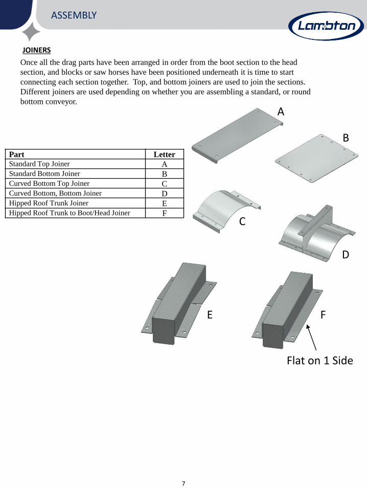
Once all the drag parts have been arranged in order from the boot section to the head
section, and blocks or saw horses have been positioned underneath it is time to start
connecting each section together. Top, and bottom joiners are used to join the sections.
Different joiners are used depending on whether you are assembling a standard, or round
bottom conveyor.
ASSEMBLY
7
Part Letter
Standard Top Joiner AStandard Bottom Joiner BCurved Bottom Top Joiner CCurved Bottom, Bottom Joiner DHipped Roof Trunk Joiner EHipped Roof Trunk to Boot/Head Joiner F
JOINERS
A
B
C
D
E F
Flat on 1 Side

ASSEMBLY
8
BOOT SECTION
The boot section will be joined to either your hopper or first section of trunking using a Top
Joiner, Bottom joiner and Side joiners. Use 5/16” x 1” hex head bolts on outside flanges,
and 5/16” x 3/4” flat head socket cap screws on the walls of the boot section to prevent any
obstructions. The boot sprocket should be checked to ensure it is centred on the shaft and
tightened adequately.
STANDARD BOOT SECTION ROUND BOTTOM BOOT SECTION
1
2
3

Intermediate trunking sections can now be joined together using side, top, and bottom joiners
for your application. All top covers should be removed and stored along with the hardware in a
safe place to minimize any possible damage or loss. Take time to familiarize yourself with your
trunking. If your conveyor is equipped with UHMW return rollers, check that the rollers are in
the centre of the trunking and tightened adequately.
During assembly of each trunk section to the next carefully inspect each joint to ensure that the
inside bottom, and side surfaces are flush. A chalk line is helpful to ensure the proper
alignment. Maximum run-out in any direction is ¼” (with all joints connected). Proper
alignment will minimize wear on flights and other potential damage to the conveyor. Make sure
that the conveyor is as horizontal as possible to minimize any performance losses.
ASSEMBLY
9
INTERMEDIATE TRUNKING

ASSEMBLY
10
HEAD SECTION
The head section of the conveyor can now be joined to the end piece of trunking using the supplied
joiners. Note: the two side joiners have been attached to the head section prior to shipping. This is
a good time to ensure the head sprocket is in the centre of the shaft and tightened.
STANDARD HEAD SECTION ROUND BOTTOM HEAD SECTION

The drag conveyor chain should be installed after all components of the drag have been joined. Start
by loosening the chain tensioners located on the boot section to its loosest position. When using
UHMW return roller trunking the chain is installed over the rollers, head sprocket, and boot sprocket.
The UHMW paddles should be facing the direction that grain is to flow and tilted at a 15-degree angle
as shown when installed to produce a downward force on the chain. UHMW paddles come in full and
part paddle sections. Low profile drags use a full paddle for every 10 ft of chain and part paddles for
the rest. Standard drags use full paddles for the full length of the chain. Refer to the below diagram
for proper fastening procedures. Fasten chains together using the supplied hardware (connecting links).
If return cups are to be installed on the chain refer to the Return Cups section of this manual.
CHAIN INSTALLATION
11
Once the drag chain has been installed and connected in the drag assembly it can be tightened by
adjusting the chain tensioners on the boot section. The tensioners should be adjusted in small
increments to ensure the boot sprocket is kept square. Chain tension is correct when deflection is
approximately ½” at a point midway between the UHMW rollers. Refer to the below diagram for
clarification.
Once the chain has been tensioned, it should be rotated at least one complete revolution through the
conveyor. Check to see that the chain and paddles are not catching on flanges or rubbing on the sides
of the trunk due to improper boot and/or head pulley alignment. Make adjustments if necessary.
Chain Tensioners Grain Flow
150
Trunk Bottom
Paddle
Part Paddle
Full Paddle

CARRY OVER RETURN CUPS
12
PaddlePaddle Attachment
Return Carry Over CupBolting Location
Return Cup Placement
Paddles Return Cups
10 ‘
Carry over Return Cups are required when using intermediate discharge slide gates in conjunction
with a head discharge gate. The Return cups will return material from the head section to the boot
section where it will again be conveyed to the intermediate discharge gate. Failure to use Return Cups
in this application will eventually lead to material build up in the head section which will cause
damage to the machine.
The purpose of using the head discharge gate is to prevent the mixing of grains. Alternatives to this
method would include having the head section discharge into a reclaim conveyor or bulk tank for
reclaim later. Carry over refers to small amount of material (typically less than 1% of conveyed
material) that does not fall through the intermediate discharge opening and will “carry over” to the
head section, either by riding on the chain assembly or some other mechanic.
Return Cups should be placed twice in every ten-foot section of chain. To accomplish this, we suggest
putting one cup near the start of the ten-foot section and the other cup near the middle of the same
section but on the opposite side of the chain as the other cup. This will stagger the cups at equal
distances throughout the drag length providing you with optimal performance.
Return Cups will be bolted on the backside of the paddles using the same holes as the paddles.
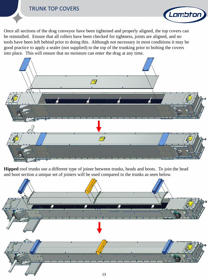
Once all sections of the drag conveyor have been tightened and properly aligned, the top covers can
be reinstalled. Ensure that all rollers have been checked for tightness, joints are aligned, and no
tools have been left behind prior to doing this. Although not necessary in most conditions it may be
good practice to apply a sealer (not supplied) to the top of the trunking prior to bolting the covers
into place. This will ensure that no moisture can enter the drag at any time.
TRUNK TOP COVERS
13
Hipped roof trunks use a different type of joiner between trunks, heads and boots. To join the head
and boot section a unique set of joiners will be used compared to the trunks as seen below.

INTERMEDIATE DISCHARGE GATES
14
Use the template bolted to the top of the gate to cut a pattern in the bottom of the conveyor
trunking then discard the template and bolt the gate directly to the bottom of the conveyor.
Once tightened ensure that the slide plate moves freely. If it does not, adjust the UHMW slide
rails that support the slide plate. These slide rails are bolted in slotted holes that allow for
adjustment. The owner assumes all responsibility for any alterations to the drag conveyor.
Cut template

Optional inlets include the Standard Top Inlet and various sizes of Pit Hoppers. Pit hoppers bolt directly
to the trunking sections while the top inlet requires field cutting the drag at the required location.
Lambton Conveyor recommends a minimum of 12” between the boot section and the start of the inlet.
Inlets bolt directly to the top of the trunking, to ensure a weather tight seal be sure to apply a quality
sealer (not supplied) around the inlet edges. More information on pit hopper foundation
recommendations and inlet sizes are located on the next page.
INLETS
15
STANDARD TOP INLET
Warning: Lambton Conveyor recommends all welding be performed prior to the installation of any
electrical components including the drive system. By not following this recommendation the owner
assumes all risks associated with this installation.
12” Min from Boot

INLETS
16
CE
ME
NT
CE
ME
NT
DRIV E OV ER G RAT ING
3. 5 S td.3. 5" St d.
Q
R
Q REPRESE NTS M I NDE PTH O F PI T
PIT SUGGESTIONS
DRAG HOPPER & DRIVE OVER GRATE
B
3" C
D
A
VIEW A-A
THROUGH RECEIVING HOPPER
3"
F
12" 12"
BO O TA-A
E
F
HH
J
P
N
G
LM
B
48", 96" O R 144"O PTI O NAL RE CEI VI NG HO PPE R
80"O PTI O NAL I NTE RM EDI AT E GA TE
HE AD
O PTI O NAL HE AD
DI SCHARGE
O PTI O NAL I NLET
MODEL A B C D E F G H J L M N P Q R
9x9 9 9 30 7∕8 25 1∕2 9 1∕4 24 9 9 16 19 3 1∕2 36 13 1∕2 29 31
9x17 9 17 30 7∕8 25 1∕2 17 1∕4 30 8 12 20 19 3 1∕2 36 13 1∕2 29 31
12x17 12 17 30 7∕8 27 17 1∕4 30 8 12 20 19 3 1∕2 36 13 1∕2 30 1∕2 31
16x17 16 17 30 7∕8 27 17 1∕4 30 8 16 20 19 3 1∕2 36 11 1∕2 30 1∕2 31
16x20 16 20 30 7∕8 30 20 1∕4 36 8 20 24 19 3 1∕2 36 11 1∕2 33 1∕2 31
20x20 20 20 30 7∕8 30 20 1∕4 42 8 20 24 19 3 1∕2 36 11 1∕2 33 1∕2 31
24x24 24 24 34 7∕8 36 27 1∕4 48 12 24 28 24 3 1∕2 37 15 1∕4 42 36
STANDARD DRAG (Dimensions in Inches)
MODEL A B C D E F G H J K L M N P Q R
9x9 9 9 ¼ 30 20
15/16
16 1/2 34 ½ 8 12 ¼ 20 31 ½ 19 1 7/8 42 1/4 22 7/16 34 ½ 31
9x17 9 17 ¼ 30 28 5/16 24 ½ 34 ½ 8 12 ¼ 20 31 ½ 19 1 7/8 42 22 7/16 X X
ROUND BOTTOM DRAG
MODEL A B C D E F G H J L M N P Q R
9x9 9 9 30 7∕8 25 1∕2 9 1∕4 24 9 9 13 19 3 1∕2 36 13 1∕2 29 31
13x11 13 11 30 7∕8 25 1∕2 15 1∕4 24 6 10 16 20 3 1∕2 36 14 1∕2 NA NA
LOW PROFILE DRAG

Top (Double Sided) Inlet Hopper
17
First determine where your hopper should be located. Next determine the proper spacing of the Side
Plates by measuring the length of the Front Hopper Plate. This is the distance that should be between
your two side plates (not the holes). Next drill the holes for the side plates and bolt them into place.
Once the side plates have been positioned at a 90-degree angle to the bottom of the trunking the
required hole can be marked out. The hole will start ¾” from the top edge of the trunk to the bottom tip
of the side plates. Once you are satisfied with the positioning of your hole mark it on the other side as
well, remove the side plates and cut the holes. For clarification refer to the below diagrams.
The four Hopper Side Plates can now be bolted to the trunking then welded into place. The plates will be
located just outside the hole with the bends facing out. Use 5/16” x ¾” button head bolts with the head of
the bolt on the inside of the trunking.
Next locate the Hopper Front Plates and bolt them into place as shown using 5/16” x ¾” hex head bolts.
Hopper Side Plates
Hopper Front Plates
Joiner Plate
Grain Deflector
Rain Shield
Bottom Tip of Side Plate

Next bolt the two Joiner Plates to the outside of the hopper side plates on each side. The Grain Deflector can
also be bolted into place as shown in the diagram. Use 5/16” x ¾” hex head bolts.
Top (Double Sided) Inlet Hopper
18
Bolt the Rain Shield to the hopper using 5/16” x ¾” hex head bolts. The hopper is now finished and should
resemble the below picture.
Grain Deflector
Joiner Plate
Rain Shield
For fixed inlet feeding the hole should be cut as far away from the head as possible and centred to improve
loading speeds.

19

20

The following instructions detail the steps required to assemble a right hand conveyor drive
assembly. For left hand drive conveyors, reconfigure the components to position the torque
arm as shown in Figure 1.
DRIVE ASSEMBLY
21
It is imperative that the torque arm be in tension when the
conveyor is under load. A torque arm mounted in compression
can cause equipment failure resulting in serious injury or death.
Figure 1 - Drive Configurations
Due to the numerous different conveyor and/or drive configurations, we cannot cover all aspects of the
drive assembly. The following instructions are general guidelines only and some components shown
may differ slightly from those supplied. Carefully read and understand all instructions before starting
any work. Again, only qualified personnel should install this equipment.
Ensure the conveyor output shaft is clean, free of burrs and properly positioned in the head. This is
also a good time to check that the head sprocket is centered and aligned on the shaft. A sprocket that
is not properly aligned will prevent the chain from tracking correctly and cause excessive wear. Follow
the manufacturer’s instructions to install the speed reducer in the 12 o’clock orientation as shown in
Figure 2. It may be necessary to relocate the lifting lug from the factory position depending on your
conveyor and/or drive configuration. (Refer to manufacturer’s instructions for housing flange bolt
torque specifications.) Secure the speed reducer to the output shaft with the supplied bushing kit
installed in the Rear Mounting Configuration with Stabilizer Ring. The output shaft should not
extend through the end cap. It may be necessary to restrain the speed reducer in the 12 o’clock
orientation until the torque arm kit is completely installed later in these instructions.
Speed reducers are shipped without oil. See the
Lubrication section in this manual for further information.

22
Using the speed reducer housing flange bolts, install the motor mount/torque arm supports and motor
mount supports as shown in Figure 3. Do not reinstall the flat washers on the bolts. Refer to the
speed reducer manufacturer’s instructions for housing flange bolt torque specifications.
DRIVE ASSEMBLY

23
Install the motor mount adapter and the motor mount adapter inner reinforcements (407 and 415
speed reducers only) to the motor mount/torque arm supports and motor mount supports as shown in
Figure 4.
Install the motor base on top of the motor base reinforcement and position above motor mount adapter
using the supplied threaded rod and flange nuts as shown in Figure 5. Excess length of threaded rod
should project downwards so it does not interfere with the motor. Ensure motor mounting holes are
positioned so that the end with fewer holes is at the front of the speed reducer where the input shaft is.
DRIVE ASSEMBLY

24
Install belt guard mounting brackets to the motor mount/torque arm supports and motor mount
supports using supplied hardware as shown in Figure 6.
DRIVE ASSEMBLY

25
Install the torque arm mounting brackets to the motor mount/torque arm supports using supplied
hardware as shown in Figure 7. Placement of the torque arm mounting brackets will depend on your
specific conveyor and/or drive configuration. Torque arm mounting brackets can be placed anywhere
along the side of the motor mount assembly, including the motor mount adapter, in order to achieve
the torque arm manufacturer’s installation specifications.
Mount the torque arm channel to the conveyor head and/or trunk section using a minimum of four
existing fasteners (two per side). Placement will depend on your specific conveyor and/or drive
configuration. Figure 8 shows the most common installation.
DRIVE ASSEMBLY
26
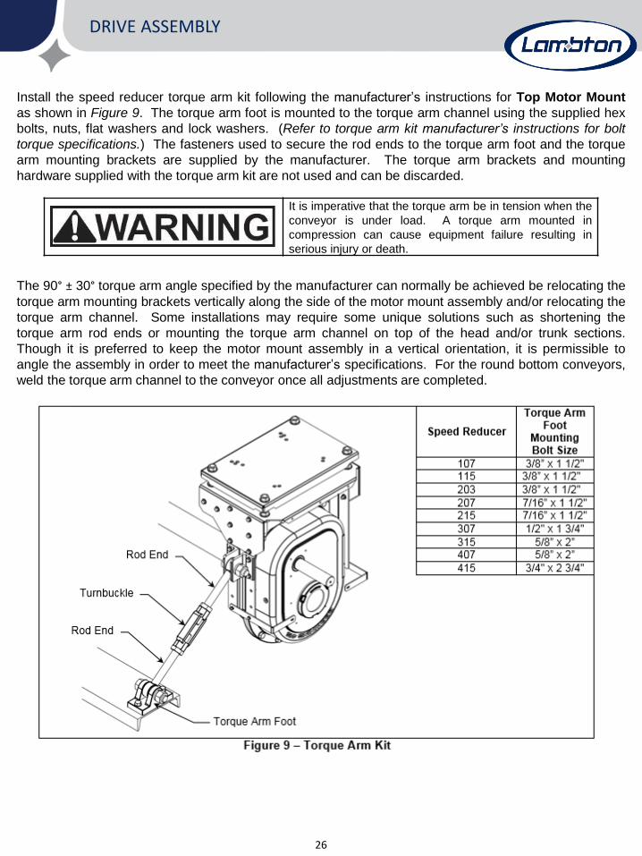
Install the speed reducer torque arm kit following the manufacturer’s instructions for Top Motor Mount
as shown in Figure 9. The torque arm foot is mounted to the torque arm channel using the supplied hex
bolts, nuts, flat washers and lock washers. (Refer to torque arm kit manufacturer’s instructions for bolt
torque specifications.) The fasteners used to secure the rod ends to the torque arm foot and the torque
arm mounting brackets are supplied by the manufacturer. The torque arm brackets and mounting
hardware supplied with the torque arm kit are not used and can be discarded.
It is imperative that the torque arm be in tension when the
conveyor is under load. A torque arm mounted in
compression can cause equipment failure resulting in
serious injury or death.
The 90° ± 30° torque arm angle specified by the manufacturer can normally be achieved be relocating the
torque arm mounting brackets vertically along the side of the motor mount assembly and/or relocating the
torque arm channel. Some installations may require some unique solutions such as shortening the
torque arm rod ends or mounting the torque arm channel on top of the head and/or trunk sections.
Though it is preferred to keep the motor mount assembly in a vertical orientation, it is permissible to
angle the assembly in order to meet the manufacturer’s specifications. For the round bottom conveyors,
weld the torque arm channel to the conveyor once all adjustments are completed.
DRIVE ASSEMBLY

27
Install motor onto motor base as shown in Figure 10.
Note: Electric motor is not provided. Always use a motor with the correct HP rating. Too small of a
motor will not supply the horsepower required to achieve capacity and damage to the motor may
occur. Too large of a motor may cause high stress on components resulting in shorter life. “Soft
Start” motors are also recommended to protect the conveyor from high torque shocks against a unit
that may have inadvertently been stopped under load or plugged. Electric motors and controls shall
be installed by a qualified electrician. Controls should be located so that the operator has a full view
of the entire operation. An amp meter for the drive motor should be installed so the operator can
easily monitor and avoid overloading the system. A magnetic starter should be used to protect your
motor when starting and stopping. It should stop the motor in case of power interruption, conductor
fault, low voltage, circuit interruption, or motor overload. The motor must be restarted manually.
Some motors have a built-in thermal protection overload protection. If this type of motor is used, use
only those with manual reset.
Disconnect power before resetting motor overloads.
Make certain electric motors are grounded.
IMPORTANT: After the motor is mounted and all controls are complete, run the motor prior to
installing sheaves and belts to check rotational direction. A conveyor chain travelling in the wrong
direction can lead to equipment failure.
If applicable, mount the fan kit to the speed reducer following the manufacturer’s instructions prior to
mounting belt guard assembly Mount the belt guard assembly to the motor mount adapter and the belt
guard mounting brackets with the supplied hardware as shown in Figure 11.
The conveyor should never operate without guards in
place. Failure to follow these precautions could result in
serious injury or death.
DRIVE ASSEMBLY

28
Install sheaves and bushings onto the reducer input shaft and motor shaft as shown in Figure 12.
Refer to bushing manufacturer’s instructions for additional information and torque specifications.
Sheaves should be installed as close to the motor and reducer as possible to prevent overhung
loads, and aligned using a straight edge to avoid excessive belt wear. Be sure drive keys are
properly installed. The drive belts can now be installed and tensioned using the motor mount
adjustment rods. Ensure adjustment rods are turned equally to keep motor sheave parallel to the
reducer sheave. Belts must be tightened sufficiently to avoid slipping which will result in excessive
wear during normal operation. Over tightening creates high stress on belts and conveyor
components resulting in shorter life. Close belt guard door and secure using supplied hardware.
DRIVE ASSEMBLY

29
Lubrication
Reducers are shipped without oil; refer to the Manufacturers owner’s manual to determine the proper
type and quantity for your application. All bearings should be lightly lubricated before initial start-up
but fully lubricated during. Some bearings are equipped with auto greasers (optional) to prevent over
lubricating. It has been our experience that most bearings are ruined from over lubricating rather than
lack of it. Pressure guns tend to break the seals, in which they are unable to retain lubricant. Ensure that
all employees are aware of this fact.
Start-Up
A final check of all parts to ensure that no foreign objects or tools have been left in the drag is a good
idea. All guards, inspection panels, and removable sections should be checked for proper placement.
The boot chain tensioners need to be adjusted to tighten the chain on the sprockets, refer to drag chain
section for more info. The drive should once again be turned by hand to check for proper tracking, and
to ensure there are no obstructions. Finally check all setscrews to ensure they are tightened.
After a check of all mentioned components carefully run the conveyor without load and check for any
problems or necessary adjustments. Make certain that the chain is running in proper alignment along
the UHMW rollers and sprockets. If adjustments are required refer to the troubleshooting section of this
manual.
Once all sections of the conveyor have been thoroughly checked, all adjustments have been made and
proper lubrication is done the conveyor can be run without load for several hours for an initial break in.
Look and listen carefully for any irregularities before running any material through the conveyor.
Once you are satisfied with the operation of your conveyor it can be put into use. At this point it may be
a good idea to check the rest of your flow system. Be sure any outlets, inlets, etc are functioning
properly.
A chart is located on the following page to assist you in recognizing and repairing any problems you
may have with your conveyor during start-up or in the future. We at Lambton Conveyor stand ready to
assist you with any problems or concerns regarding the operation of our equipment. Feel free to call
upon us at any time for information or assistance.

30
Troubleshooting
Problem Cause Solution
Low Capacity
Improper Chain Speed
Loose Chain
Improper Feeding
Plugged
Check for proper shaft RPM
Check chain tension
Check inlet grain level
Check discharges
Noisy Operation
Loose UHMW Paddles
Bottom not Aligned
Worn Return Rollers
Worn Drive Components
Worn Sprocket
Check all bolts and chains
Check trunking joints for alignment
Check return rollers (should turn easily)
Check oil levels and shaft seals
V-belt alignment, and tension
Replace
Uneven UHMW (paddle wear)Conveyor Misalignment
Sprocket Slipped on shaft
Check conveyor alignment
Check sprocket set screws
Excessive carry-over Discharge Gates not fully open Check gate operation
Uneven Sprocket Wear
Worn Chain
Improper Alignment
Carry-over into discharge
Replace Chain
Check Sprocket alignment
Check inlet location (pg. 10)
Tel #: (519) 627-8228
Toll Free #: 1 (888) 239-9713
Fax #: (519) 627-0250

Maintenance
31
Warning! Power must be locked out prior to any maintenance or repairs being performed on the
equipment to prevent accidental start-up. Failure to follow this precaution may result in serious
injury or death.
To extend the life of your drag conveyor perform the tasks listed frequently. Like all equipment the overall
life of your drag conveyor can be greatly reduced if it is abused and poorly maintained.
Check all bearings and moving parts daily during operation for any problems
Lubricate all bearings, and drive components as needed according to the manufacturers recommendations.
Inspect the v-belts frequently for proper tension and wear. Replace when necessary.
Check drag chain, and sprockets periodically for wear, damage and proper adjustment. Any worn or
broken paddles should be replaced or straightened.
Tightening of bolts, electrical connections, and switches
Routine maintenance may include but is not limited to the above.

Employer/Employee Training Sign-off
32
Lambton Conveyor has included this training sign-off sheet for the owner/operator to make use of in
the training, installation, and operation processes of the equipment described in this manual. Read the
entire manual, sign-off and date the chart below.
Date Employee Signature Employee Name Printed

Quality Analysis Report
33

![Welcome []...• Welcome & Introductions • GLR Inc. Update • GLR Economic Development Update • GLR Workforce Development Update • GLR Communications Update • Wrap-Up 1,414](https://img.pdfslide.us/doc/110x75/5ed221c2821d0855e2414db8/welcome-a-welcome-introductions-a-glr-inc-update-a-glr-economic.jpg)