Embed Size (px)
Citation preview

OWNER’S MANUAL
TEMPERATURE SENSORSModels ST-100, ST-110, ST- 150, ST-200, and ST-300
APOGEE INSTRUMENTS, INC. | 721 WEST 1800 NORTH, LOGAN, UTAH 84321, USATEL: (435) 792-4700 | FAX: (435) 787-8268 | WEB: APOGEEINSTRUMENTS.COM
Copyright © 2020 Apogee Instruments, Inc.

2
TABLE OF CONTENTS
Owner’s Manual...............................................................................................................................................................................1
Table of Contents.............................................................................................................................................................................2
Certificate of Compliance........................................................................................................................................................3
Introduction............................................................................................................................................................................4
Sensor Models.........................................................................................................................................................................5
Specifications..........................................................................................................................................................................6
Deployment and Installation...................................................................................................................................................8
Operation and Measurement..................................................................................................................................................9
Maintenance and Recalibration............................................................................................................................................15
Troubleshooting and Customer Support...............................................................................................................................16
Return and Warranty Policy..................................................................................................................................................18

3
CERTIFICATE OF COMPLIANCE
EU Declaration of Conformity
This declaration of conformity is issued under the sole responsibility of the manufacturer:
Apogee Instruments, Inc.721 W 1800 NLogan, Utah 84321USA
for the following product(s):
Models: ST-100, ST-110, ST-150, ST-200, ST-300 Type: Temperature Sensor
The object of the declaration described above is in conformity with the relevant Union harmonization legislation:
2014/30/EU Electromagnetic Compatibility (EMC) Directive2011/65/EU Restriction of Hazardous Substances (RoHS 2) Directive2015/863/EU Amending Annex II to Directive 2011/65/EU (RoHS 3)
Standards referenced during compliance assessment:
EN 61326-1:2013 Electrical equipment for measurement, control and laboratory use – EMC requirementsEN 50581:2012 Technical documentation for the assessment of electrical and electronic products with respect to
the restriction of hazardous substances
Please be advised that based on the information available to us from our raw material suppliers, the products manufactured by us do not contain, as intentional additives, any of the restricted materials including lead (see note below), mercury, cadmium, hexavalent chromium, polybrominated biphenyls (PBB), polybrominated diphenyls (PBDE), bis(2-ethylhexyl) phthalate (DEHP), butyl benzyl phthalate (BBP), dibutyl phthalate (DBP), and diisobutyl phthalate (DIBP). However, please note that articles containing greater than 0.1% lead concentration are RoHS 3 compliant using exemption 6c.
Further note that Apogee Instruments does not specifically run any analysis on our raw materials or end products for the presence of these substances, but rely on the information provided to us by our material suppliers.
Signed for and on behalf of:Apogee Instruments, April 2020
Bruce BugbeePresidentApogee Instruments, Inc.

4
INTRODUCTIONTemperature is generally thought of as the relative degree of ‘hotness’ or ‘coldness’ of a specific object or material. In actuality, temperature is a measure of the average thermal energy (internal kinetic energy) of an object. Thermal energy is associated with the motion (kinetic energy) of the atoms and molecules making up the object/material. Higher temperatures correspond to higher thermal energies (faster motion of atoms and molecules), whereas colder temperatures correspond to lower thermal energies (slower motion of atoms and molecules).
Properties of materials, and nearly all biological, chemical, and physical processes, are temperature dependent. Temperature is also a fundamental weather variable. As a result, temperature is perhaps the most widely measured environmental variable.
Thermometers are sensors that measure temperature. Thermometers are often electronic, with multiple options available. The main advantages of thermistors over other electronic thermometers (thermocouples, platinum resistance thermometers) are high signal-to-noise ratio, requirement of only a single-ended channel for measurement, and low cost, while still maintaining comparable accuracy.
Apogee Instruments ST-100 temperature sensors consist of a precision thermistor enclosed in a waterproof rubber covering, a precision bridge resistor, and lead wires to connect the sensor to a measurement device. ST-100 sensors are weatherproof and are designed for continuous temperature measurement in air, soil, or water.
ST-110 temperature sensors consist of a precision thermistor, a precision bridge resistor, and lead wires to connect the sensor to a measurement device. ST-110 sensors are weatherproof, have excellent long-term stability, but do not offer the same level of ingress protection as the ST-100. The ST-110 is designed for continuous air temperature measurement when housed in the TS-100 aspirated radiation shield. Thermal conductivity to the precision thermistor is minimized by using constantan wire, which has twenty-fold lower thermal conductivity than copper wire.
ST-150 is a platinum resistive thermometer (PRT) enclosed in a stainless steel sheath, and lead wires to connect the sensor to a measurement device. The sensor is weatherproof and is designed for continuous air temperature measurement when housed in the TS-100 aspirated radiation shield. The ST-150 is designed to be used with dataloggers that have resistors built in.
ST-200 temperature sensors have a fine-wire precision thermistor, precision bridge resistor, and lead wires, but the thermistor is not packaged in a weatherproof housing. ST-200 sensors are weather resistant and are designed for temperature measurement of delicate surfaces (e.g., leaves, fruits) and small samples (where a narrow field of view infrared radiometer may not be suitable due to the integration over the conical field of view), or applications where rapid response is required.
ST-300 is a platinum resistance thermometer (PRT), consisting of a platinum resistive element enclosed in a stainless steel sheath, and lead wires to connect the sensor to a measurement device. ST-300 sensor are weatherproof and is designed for continuous air temperature measurement when housed in the TS-100 aspirated radiation shield.

5
All Apogee thermistor temperature sensors output an analog voltage (when supplied with an input voltage) that is related to thermistor resistance. Resistance is directly related to temperature.
SENSOR MODELSThe ST-100 temperature sensor includes a rugged, weatherproof housing and can be exposed to a wide range of environmental conditions, including submersion in water and burial in soil/porous media.
The ST-200 temperature sensor does not include the weatherproof housing and is designed for fast response measurements, or measurements of small samples and fragile surfaces.
The ST-110 thermistor temperature sensor is designed for use inside the Apogee fan-aspirated radiation shield, model TS-100.
The ST-150 PRT temperature sensor is an accurate and durable sensor for use in all applications, including air temperature measurements in the TS-100.
The ST-300 PRT temperature sensor is a highly accurate (1/10 DIN) and durable sensor for use in all applications, including for air temperature measurements in the TS-100.
Sensor model number and serial number are located on a label near the pigtail lead wires. If you need the manufacturing date of your sensor, please contact Apogee Instruments with the serial number of your sensor.

6
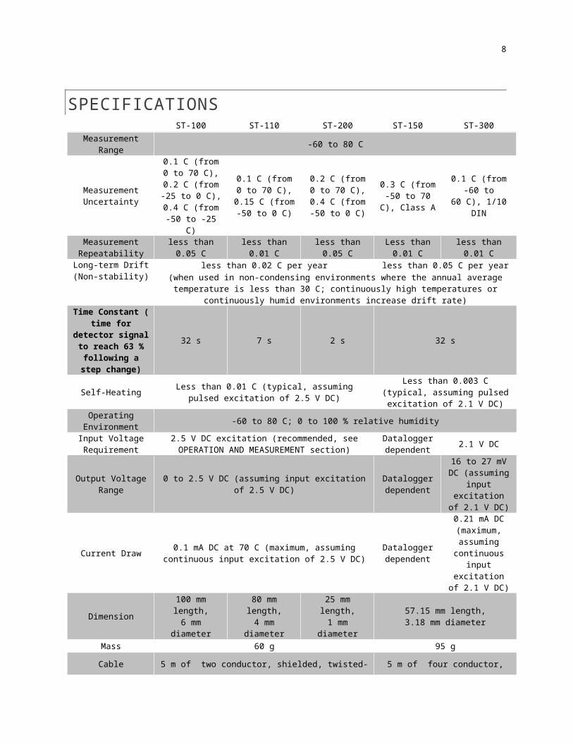
SPECIFICATIONSST-100 ST-110 ST-200 ST-150 ST-300
Measurement Range -60 to 80 C
Measurement Uncertainty
0.1 C (from 0 to 70 C), 0.2 C (from -25 to 0 C), 0.4 C
(from-50 to -25 C)
0.1 C (from 0 to 70 C), 0.15 C
(from -50 to 0 C)
0.2 C (from 0 to 70 C), 0.4 C (from
-50 to 0 C)
0.3 C (from -50 to 70 C), Class A
0.1 C (from -60 to60 C), 1/10 DIN
Measurement Repeatability less than 0.05 C less than 0.01 C less than 0.05 C Less than 0.01 C less than 0.01 C
Long-term Drift(Non-stability)
less than 0.02 C per year less than 0.05 C per year(when used in non-condensing environments where the annual average temperature is less than 30 C;
continuously high temperatures or continuously humid environments increase drift rate)Time Constant ( time for detector signal to reach 63 % following
a step change)
32 s 7 s 2 s 32 s
Self-Heating Less than 0.01 C (typical, assuming pulsed excitation of 2.5 V DC)
Less than 0.003 C (typical, assuming pulsed excitation of 2.1 V DC)
Operating Environment -60 to 80 C; 0 to 100 % relative humidity
Input Voltage Requirement
2.5 V DC excitation (recommended, see OPERATION AND MEASUREMENT section)
Datalogger dependent 2.1 V DC
Output Voltage Range 0 to 2.5 V DC (assuming input excitation of 2.5 V DC) Datalogger dependent
16 to 27 mV DC (assuming input
excitation of 2.1 V DC)
Current Draw 0.1 mA DC at 70 C (maximum, assuming continuous input excitation of 2.5 V DC)
Datalogger dependent
0.21 mA DC (maximum, assuming
continuous input excitation of 2.1 V
DC)
Dimension 100 mm length,6 mm diameter
80 mm length,4 mm diameter
25 mm length,1 mm diameter
57.15 mm length,3.18 mm diameter
Mass 60 g 95 g
Cable
5 m of two conductor, shielded, twisted-pair wire; additional cable available in multiples of 5 m; TPR jacket (high water resistance, high UV stability, flexibility in cold conditions);
pigtail lead wires
5 m of four conductor, shielded, twisted-pair wire; additional cable available in multiples of 5 m; TPR
jacket (high water resistance, high UV stability, flexibility in cold conditions);
pigtail lead wires

7
Calibration Traceability
Apogee ST-100, ST-110, and ST-200 temperature sensors are not factory calibrated, but come with a generic calibration (see Steinhart-Hart coefficients in OPERATION AND MEASUREMENT section). A custom calibration can be derived by comparing the temperature from the thermistor to a reference temperature measurement. Often, a simple offset can be used to make measured temperature match reference temperature.
Apogee ST-110, ST-150, and ST-300 temperature sensors are factory verified to ensure accuracy. Sensors are compared for absolute temperature against the mean of two reference PRTs in a constant temperature bath, over a range of approximately -35 to 60 C. The reference PRT calibrations are directly traceable to NIST.
8
DEPLOYMENT AND INSTALLATIONApogee ST Series temperature sensors are designed to be mounted inside solar radiation shields, such as the model TS-100 fan aspirated radiation shield (see picture below). ST-100, ST-150, and ST-300 sensors can also be buried in soil/porous media, or submerged in water. ST-200 sensors have thin, flexible wires near the fine-wire thermistor and are less sensitive to breakage than similarly-sized fine-wire thermocouples.
The temperature measurement returned by a temperature sensor is the temperature for the sensor itself and not that of the environment the sensor is in, unless the sensor is in thermal equilibrium with the environment. In order to get representative temperature measurements, ST series sensors must be in thermal contact with the medium of interest. Accurate air temperature measurement requires a radiation shield (see picture below) to minimize the effects of shortwave radiation absorption (causes warming; occurs during the day) and longwave radiation emission (causes cooling; occurs on clear nights) by the sensor. Proper ventilation is also required to ensure coupling and thermal equilibrium with air. Condensation on air temperature sensors can pose a problem because it is a source of latent heat that can warm the sensor. When the condensed water evaporates, it cools the sensor via removal of latent heat (evaporational cooling).
During installation of ST-100, ST-150, and ST-300 sensors in soil, care should be taken to minimize soil disturbance, which may potentially alter soil thermal properties.
Top left: SP-230 Heated PyranometerCenter: TS-100 Fan Aspirated Radiation ShieldRight: RM Young 41303 Static Solar Radiation Shield.

9
OPERATION AND MEASUREMENT
VERY IMPORTANT: Apogee changed all wiring colors of our bare-lead sensors in March 2018. To ensure proper connection to your data device, please note your serial number then use the appropriate wiring configuration below.
Wiring for ST-100 Serial Numbers 2725 and above, ST-110 Serial Numbers 2725 and above, and ST-200 Serial Numbers 1352 and above
Wiring for ST-100 Serial Numbers range 0-2724, ST-110 Serial Numbers range 0-2724, and ST-200 Serial Numbers range 0-1351
Plug each wire into the appropriate data logger terminal following the illustrations below:
Blue: Analog Ground (negative thermistor lead)
Red: Excitation Channel (excitation for thermistor)
Black: Single-ended channel (positive thermistor lead)
Clear: Ground (shield wire)
White: Single-ended channel (positive thermistor lead)
Red: Excitation channel (excitation for thermistor)
Black: Ground (negative thermistor lead)
Clear: Shield/Ground

NOTE: The wiring diagram above is based off the new wiring colors for serial numbers 2725 or 1352 and above.
10
Measurement devices (e.g., datalogger, controller) do not measure resistance directly, but determine resistance from a half-bridge measurement, where an excitation voltage is input across the thermistor and an output voltage is measured across the bridge resistor.
An excitation voltage of 2.5 V DC is recommended to minimize self-heating and current drain, while still maintaining adequate measurement sensitivity (mV output from thermistor per C). However, other excitation voltages can be used. Decreasing the excitation voltage will decrease self-heating and current drain, but will also decrease thermistor measurement sensitivity. Increasing the excitation voltage will increase thermistor measurement sensitivity, but will also increase self-heating and current drain.
Conversion of Thermistor Resistance to Temperature
The thermistor is a resistive element, where resistance changes with temperature. Thermistor resistance (RT, in Ω) is measured with a half-bridge measurement, requiring a known excitation voltage input (VEX) and a measurement of output voltage (VOUT):
RT=24900( V EXVOUT−1)
(1)
where 24900 is the resistance of the bridge resistor in Ω. From resistance, temperature (TK, in Kelvin) is calculated with the Steinhart-Hart equation and thermistor specific coefficients:
TK=1
A+B ln(RT )+C ( ln(RT ))3
(2)
where A = 1.129241 x 10⁻³, B = 2.341077 x 10⁻⁴, and C = 8.775468 x 10⁻⁸ (Steinhart-Hart coefficients).

White: High Side of Differential Channel 1
Green: High Side of Differential Channel 2
Blue: Low Side of Differential Channel 2
Black: Low Side of Differential Channel 1
Clear: Ground (shield wire)
11
If desired, measured temperature in Kelvin can be converted to Celsius (TC):
TC=TK−273.15 . (3)
ST-150
The ST-150 does not include bridge resistors and is therefore meant to be used with dataloggers or controllers that are capable of internally converting the measured resistance from the ST-150 into a temperature reading. Although the ST-150 can be used in a 2-wire or 3-wire measurement configuration, a 4-wire configuration is always preferred for best accuracy. If a half-bridge measurement is desired, the same wiring and bridge resistors detailed below in the ST-300 section can be used to achieve the measurement.
Note: as shown in the schematic, the 4-wire PRT can be directly measured. The black and white wires are electrically connected to one side of the PRT while the red and green wires are electronically connected to the other side of the PRT.

12
ST-300 PRT
Connect the sensor to a measurement device (meter, datalogger, controller) capable of inputting 2.1 V DC, and measuring and displaying or recording a millivolt (mV) signal (an input measurement range of 16 to 27 mV is required to cover the entire temperature range of the sensor). In order to maximize measurement resolution and signal-to-noise ratio, the input range of the measurement device should closely match the output range of the thermistor.
VERY IMPORTANT: Apogee changed all wiring colors of our bare-lead sensors in March 2018. To ensure proper connection to your data device, please note your serial number then use the appropriate wiring configuration below.
Wiring for ST-300 Serial Numbers 1076 and above
Wiring for ST-300 Serial Numbers range 0-1075
White: Analog Ground
Black: Low Side of Differential Channel 2
Green: Low Side of Differential Channel 1
Orange: PRT Excitation Channel
White: High Side of Differential Channel 1
Black: Low Side of Differential Channel 1
Green: High Side of Differential Channel 2
Yellow: Analog Ground
Blue: Low Side of Differential Channel 2
Red: Excitation channel (excitation for PRT)
Clear: Shield/Ground

Note: as shown in the schematic, the 4-wire PRT can be directly measured without the bridge resistors. The blue and yellow wires are electrically connected to one side of the PRT while the green and black wires are electrically connected to the other side of the PRT.
NOTE: The wiring diagram below is based off the new wiring colors for serial numbers 1076 and above.
13
Measurement of PRT resistance is very similar to measurement of thermistor resistance, where a half-bridge measurement is used. An excitation voltage is input across the bridge resistor and an output voltage is measured across the PRT.
An excitation voltage of 2.1 V DC is recommended to minimize current drain, while still maintaining an adequate voltage signal. However, other excitation voltages can be used. Decreasing the excitation voltage will decrease current drain, but will also decrease output voltage. Increasing the excitation voltage will increase output voltage, but will also increase current drain.
Conversion of PRT Resistance to Temperature
The PRT is a resistive element, where resistance changes with temperature. PRT resistance (RPRT, in Ω) is measured with a half-bridge measurement, requiring a known excitation voltage input (VEX) and a measurement of output voltage (VOUT):
White: Analog Ground
Black: Low Side of Differential Channel 2
Green: Low Side of Differential Channel 1
Orange: PRT Excitation Channel

14
RPRT=100ΩV PRTV 100Ω (1)
where 100 Ω is resistance of the bridge resistor, V100Ω is the voltage measured across the 100 Ω bridge resistor, and VPRT is the voltage measured across the PRT. From resistance, temperature (TC, in Celsius) is calculated with:
T C=−A+√A2−4 B(1−RPRT100 )
2B (2)
where A = 3.9083 x 10⁻³, B = 5.7750 x 10⁻⁷, and C = 4.1830 x 10⁻¹².

15

16
MAINTENANCE AND RECALIBRATIONWhen sensors are not in use, it is recommended that they be removed from the measurement environment, cleaned, and stored. ST series temperature sensors used to measure air temperature should be periodically cleaned to remove all dust and debris.
Apogee ST-100 temperature sensors are weatherproof and can be submerged in water or buried in soil/porous media. ST-110 sensors are weatherproof and designed for air temperature measurements inside radiation shields. ST-200 series sensors are weather resistant, but not weatherproof. When sensors are not in use, it is recommended that they be removed from the measurement environment, cleaned, and stored. ST series temperature sensors used to measure air temperature should be periodically cleaned to remove all dust and debris.

17
TROUBLESHOOTING AND CUSTOMER SUPPORTIndependent Verification of Functionality
Apogee ST Series thermistor temperature sensors yield a resistance proportional to temperature. A quick and easy check of thermistor/sensor functionality can be accomplished with an ohmmeter. Connect the lead wires of the ohmmeter to the red and white wires from the sensor. The resistance should read 10 kΩ (10,000 ohms) at 25 C. If sensor temperature is less than 25 C, resistance will be higher. If sensor temperature is greater than 25 C, resistance will be lower. Connect the lead wires of the ohmmeter to the white and black wires from the sensor. The resistance should read 24.9 kΩ, and should not vary. Connect the lead wires of the ohmmeter to the red and black wires from the sensor. The resistance should be the sum of resistances measured across the red and white wires, and white and black wires (e.g., 10 kΩ plus 24.9 kΩ at 25 C).
Apogee ST-300 temperature sensors yield a resistance proportional to temperature. A quick and easy check of sensor functionality can be accomplished with an ohmmeter. Connect the lead wires of the ohmmeter to the blue/yellow and green/black wires from the sensor. The resistance should read 100Ω (0.1 kΩ) at 0 C. If the sensor temperature is less than 0 C, the resistance will be lower. If the sensor temperature is greater than 0 C, the resistance will be higher. The blue and yellow wires are connected internally, without a resistor between them; continuity between blue and yellow wires indicates both wires are functional. Similarly, the green and black wires are connected internally, without a resistor between them; continuity between green and black wires indicates both wires are functional. Connect the lead wires of the ohmmeter to the green/black and white wires from the sensor. The resistance should read 100 Ω, and should not vary. Connect the lead wires of the ohmmeter to the white and red wires from the sensor. The resistance should read 10 kΩ, and should not vary. Connect the lead wires of the ohmmeter to the blue/yellow and red wires from the sensor. The resistance should be the sum of the resistances measured across the blue/yellow and green/black wires, green/black and white wires, and white and red wires (e.g., 100 Ω plus 100 Ω plus 10 kΩ at 0 C).
Compatible Measurement Devices (Dataloggers/Controllers/Meters)
Measurement of thermistor resistance requires an input excitation voltage, where 2.5 V DC is recommended. Measurement of ST-300 PRT resistance also requires an input excitation voltage, where 2.1 V DC is recommended. A compatible measurement device should have the capability to supply the necessary voltage.
The sensitivity (mV output from thermistor per C) of the temperature measurement varies with the excitation voltage, and varies as a function of temperature. With an excitation voltage of 2.5 V DC, the sensitivity is lowest near the ends of the measurement range, -60 and 80 C. A compatible measurement device (e.g., datalogger or controller) should have resolution of at least 0.6 mV, in order to produce temperature resolution of less than 0.1 C across the entire temperature measurement range (less than 0.05 C from -35 to 45 C).
The sensitivity (mV output from PRT per C) of the temperature measurement from the ST-300 PRT is approximately constant across the entire measurement range. With an excitation voltage of 2.1 V DC, a compatible measurement device should have resolution of at least 0.008 mV, in order to produce temperature resolution of less than 0.1 C across the entire temperature measurement range.
An example datalogger program for Campbell Scientific dataloggers can be found on the Apogee webpage at http://www.apogeeinstruments.com/content/Thermistor-Temperature-Sensor.CR1.

18
Modifying Cable Length
When the sensor is connected to a measurement device with high input impedance, sensor output signals are not changed by splicing on additional cable in the field. Tests have shown that if the input impedance of the measurements device is 1 mega-ohm or higher then there is negligible effect on ST series temperature sensors, even after adding up to 100 m of cable. See Apogee webpage for details on how to extend sensor cable length (http://www.apogeeinstruments.com/how-to-make-a-weatherproof-cable-splice/). For cable extensions, shielded, twisted pair cable is recommended, in order to minimize electromagnetic interference. This is particularly important for long lead lengths in electromagnetically noisy environments.
The precision bridge resistor is located at the pigtail end of the ST-300 cable. Thus, the ST-300 temperature sensor cables should not be shortened, otherwise the bridge resistor will be removed.

19
RETURN AND WARRANTY POLICY
RETURN POLICY
Apogee Instruments will accept returns within 30 days of purchase as long as the product is in new condition (to be determined by Apogee). Returns are subject to a 10 % restocking fee.
WARRANTY POLICY
What is CoveredAll products manufactured by Apogee Instruments are warranted to be free from defects in materials and craftsmanship for a period of four (4) years from the date of shipment from our factory. To be considered for warranty coverage an item must be evaluated either at our factory or by an authorized distributor.
Products not manufactured by Apogee (spectroradiometers, chlorophyll content meters, EE08-SS probes) are covered for a period of one (1) year.
What is Not CoveredThe customer is responsible for all costs associated with the removal, reinstallation, and shipping of suspected warranty items to our factory.
The warranty does not cover equipment that has been damaged due to the following conditions:
1. Improper installation or abuse.
2. Operation of the instrument outside of its specified operating range.
3. Natural occurrences such as lightning, fire, etc.
4. Unauthorized modification.
5. Improper or unauthorized repair.
Please note that nominal accuracy drift is normal over time. Routine recalibration of sensors/meters is considered part of proper maintenance and is not covered under warranty.
Who is CoveredThis warranty covers the original purchaser of the product or other party who may own it during the warranty period.
What Apogee Will DoAt no charge Apogee will:
1. Either repair or replace (at our discretion) the item under warranty.
2. Ship the item back to the customer by the carrier of our choice.
Different or expedited shipping methods will be at the customer’s expense.

20
How To Return An Item 1. Please do not send any products back to Apogee Instruments until you have received a Return Merchandise Authorization (RMA) number from our technical support department by calling (435) 245-8012 or by submitting an online RMA form at www.apogeeinstruments.com/tech-support-recalibration-repairs/. We will use your RMA number for tracking of the service item.
2. Send all RMA sensors and meters back in the following condition: Clean the sensor’s exterior and cord. Do not modify the sensors or wires, including splicing, cutting wire leads, etc. If a connector has been attached to the cable end, please include the mating connector – otherwise the sensor connector will be removed in order to complete the repair/recalibration.
3. Please write the RMA number on the outside of the shipping container.
4. Return the item with freight pre-paid and fully insured to our factory address shown below. We are not responsible for any costs associated with the transportation of products across international borders.
5. Upon receipt, Apogee Instruments will determine the cause of failure. If the product is found to be defective in terms of operation to the published specifications due to a failure of product materials or craftsmanship, Apogee Instruments will repair or replace the items free of charge. If it is determined that your product is not covered under warranty, you will be informed and given an estimated repair/replacement cost.
Apogee Instruments, Inc. 721 West 1800 North Logan, UT84321, USA
PRODUCTS BEYOND THE WARRANTY PERIOD
For issues with sensors beyond the warranty period, please contact Apogee at [email protected] to discuss repair or replacement options.
OTHER TERMS
The available remedy of defects under this warranty is for the repair or replacement of the original product, and Apogee Instruments is not responsible for any direct, indirect, incidental, or consequential damages, including but not limited to loss of income, loss of revenue, loss of profit, loss of wages, loss of time, loss of sales, accruement of debts or expenses, injury to personal property, or injury to any person or any other type of damage or loss.
This limited warranty and any disputes arising out of or in connection with this limited warranty ("Disputes") shall be governed by the laws of the State of Utah, USA, excluding conflicts of law principles and excluding the Convention for the International Sale of Goods. The courts located in the State of Utah, USA, shall have exclusive jurisdiction over any Disputes.
This limited warranty gives you specific legal rights, and you may also have other rights, which vary from state to state and jurisdiction to jurisdiction, and which shall not be affected by this limited warranty. This warranty extends only to you and cannot by transferred or assigned. If any provision of this limited warranty is unlawful, void or unenforceable, that provision shall be deemed severable and shall not affect any remaining provisions. In case of any inconsistency between the English and other versions of this limited warranty, the English version shall prevail.
This warranty cannot be changed, assumed, or amended by any other person or agreement.
APOGEE INSTRUMENTS, INC. | 721 WEST 1800 NORTH, LOGAN, UTAH 84321, USA

21
TEL: (435) 792-4700 | FAX: (435) 787-8268 | WEB: APOGEEINSTRUMENTS.COM
Copyright © 2020 Apogee Instruments, Inc.