Embed Size (px)
Citation preview

OWNER’S MANUAL
Genius
TEAMBMPRO.COM


Born by the innovative spirit of our parent company Setec, with over 50 years’ experience in power solutions, and design and manufacturing facilities in Melbourne, we are the leading experts in RV power management.
Inspired by the great Australian outdoors, we have created a range of rugged, smart and reliable products to power your adventures.
Our range of battery chargers, monitors and power management systems for caravans gives you peace of mind when you are on the road, so that you can relax in even the most far-flung destinations, knowing that you have control over your vehicle power.
To learn more about the BMPRO range of products, please visit our website teambmpro.com
TEAMBMPRO
.COM
POWERING YOUR ADVENTURES
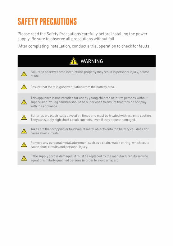
Failure to observe these instructions properly may result in personal injury, or loss of life.
Ensure that there is good ventilation from the battery area.
This appliance is not intended for use by young children or infirm persons without supervision. Young children should be supervised to ensure that they do not play with the appliance.
Batteries are electrically alive at all times and must be treated with extreme caution. They can supply high short circuit currents, even if they appear damaged.
Take care that dropping or touching of metal objects onto the battery cell does not cause short circuits.
Remove any personal metal adornment such as a chain, watch or ring, which could cause short circuits and personal injury.
If the supply cord is damaged, it must be replaced by the manufacturer, its service agent or similarly qualified persons in order to avoid a hazard.
SAFETY PRECAUTIONSPlease read the Safety Precautions carefully before installing the power supply. Be sure to observe all precautions without fail
After completing installation, conduct a trial operation to check for faults.
WARNING
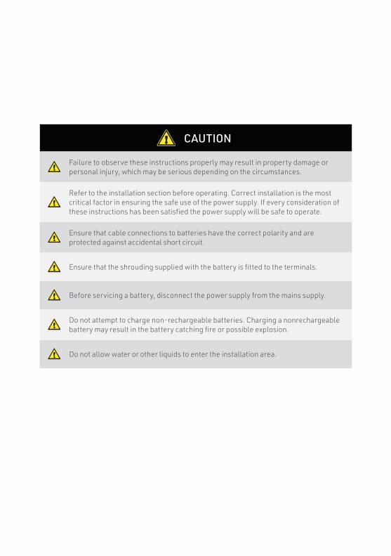
Failure to observe these instructions properly may result in property damage or personal injury, which may be serious depending on the circumstances.
Refer to the installation section before operating. Correct installation is the most critical factor in ensuring the safe use of the power supply. If every consideration of these instructions has been satisfied the power supply will be safe to operate.
Ensure that cable connections to batteries have the correct polarity and are protected against accidental short circuit.
Ensure that the shrouding supplied with the battery is fitted to the terminals.
Before servicing a battery, disconnect the power supply from the mains supply.
Do not attempt to charge non-rechargeable batteries. Charging a nonrechargeable battery may result in the battery catching fire or possible explosion.
Do not allow water or other liquids to enter the installation area.
CAUTION

6
The BMPRO product range is proudly designed and manufactured in Melbourne, Australia, and represent a high-quality product that will power your adventures for years to come.
DISCLAIMER BMPRO accepts no liability for any loss or damage which may occur from the improper or unsafe use of its products. Warranty is only valid if the unit has not been modified or misused by the customer.Copyright © 2019
MANUAL PART 033930 REV 1C
7
CONTENTS
SAFETY PRECAUTIONS 4
ABOUT THE GENIUS-II POWER SUPPLY 8
DESCRIPTION OF PARTS 9
INSTALLING THE GENIUS-II POWER SUPPLY 10 Personnel 10 Ventilation, Orientation and Thermal Considerations 10 Mounting 10 Mains Cable 10 Load, Battery and External DC Input Connections 11 Remote Load-Isolator Switch Connection 14 Battery Connection / Disconnection Procedure 15
BATTERIES 16 Paralleling Batteries 16 Storage 17 Deeply Discharged Batteries 17
SERVICING 18
FUNCTIONAL DESCRIPTION 18 Functional Diagram 18 AC/DC Power Supply 19 Fault Protection 19 Fusing 19 Battery Charging Features 19 Battery Charging Management 20 Battery Charging Store Mode 20
LED INDICATOR 21
SPECIFICATIONS 22
REPAIRS & AFTER-SALES SERVICE 22
WARRANTY TERMS AND CONDITIONS 23

8
ABOUT THE GENIUS-II POWER SUPPLYThe Genius-II has been designed for use in caravans and similar recreational vehicles, providing a DC power system with optional battery back up. The units operate from 240 Vac and provide an isolated 13.65 Vdc output at 35 A for powering the load and charging the caravan battery. All the necessary protection and operating features for the load and battery are provided. An optional DC input is also provided to enable battery charging and powering of the load from an external +13.8 V DC power source.
The unit is fully enclosed ready for direct wall mounting. All connections are at the base of unit providing convenient wiring and installation. User access to all load and battery fusing has been provided at the base of the unit.
The Genius-II is available in two different battery charge currents.
WHAT’S INCLUDEDIncluded with this product are:
9 9 Genius-II Power Supply9 9 Genius-II Owner’s Manual
Table 1: Genius II Models and their respective maximum battery charge current ratings
MODEL BATTERY CHARGE CURRENT
Genius-II Genius-IIA Genius-IIN 15A
Genius-IIH Genius-IIHA Genius-IIHN 30A
9
DESCRIPTION OF PARTS
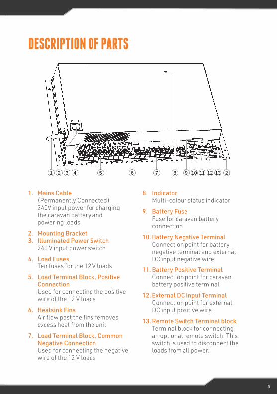
1. Mains Cable (Permanently Connected) 240V input power for charging the caravan battery and powering loads
2. Mounting Bracket3. Illuminated Power Switch
240 V input power switch
4. Load FusesTen fuses for the 12 V loads
5. Load Terminal Block, Positive ConnectionUsed for connecting the positive wire of the 12 V loads
6. Heatsink FinsAir flow past the fins removes excess heat from the unit
7. Load Terminal Block, Common Negative ConnectionUsed for connecting the negative wire of the 12 V loads
8. IndicatorMulti-colour status indicator
9. Battery FuseFuse for caravan battery connection
10. Battery Negative TerminalConnection point for battery negative terminal and external DC input negative wire
11. Battery Positive TerminalConnection point for caravan battery positive terminal
12. External DC Input TerminalConnection point for external DC input positive wire
13. Remote Switch Terminal blockTerminal block for connecting an optional remote switch. This switch is used to disconnect the loads from all power.
Names and Functions of Parts
Mains Cable (permanently connected)
240 V input power for charging the caravan battery and powering loads
Mounting Bracket
Illuminated Power Switch240 V input power switch
Load FusesTen fuses for the 12 V loads
Load Terminal Block, Positive Connection
Used for connecting the positive wire of the 12 V loads
Heatsink FinsAir flow past the fins removes excess heat from the unit
Load Terminal Block, Common Negative Connection
Used for connecting the negative wire of the 12 V loads
IndicatorMulti-colour status indicator
Battery FuseFuse for caravan battery connection
Battery Negative TerminalConnection point for battery negative terminal and external DC input negative wire
Battery Positive TerminalConnection point for caravan battery positive terminal
External DC Input TerminalConnection point for external DC inputpositive wire
Remote Switch Terminal blockTerminal block for connecting an optional remote switch. This switch is used to disconnect the loads from all power.
6
10
11
12
13
9
8
7
6
5
4
3
2
1
3 4 7 12 13821 5 111096 2

10
INSTALLING THE GENIUS-II POWER SUPPLYPERSONNELInstallation is to be carried out only by suitable qualified personnel.
VENTILATION, ORIENTATION AND THERMAL CONSIDERATIONSThe preferred orientation is with the cooling fins vertical and located such that there is a minimum of 80 mm free air space above and below them. This allows for the lowest operating temperature of the internal electronics and hence the highest reliability of the product.
The final enclosure must also provide adequate ventilation to the outside world (or larger internal cavity) to prevent excessive heating of the air within the enclosure.
The unit is rated to provide full power in both vertical and horizontal orientations with enclosure air temperatures up to 50°C.
Note: The enclosure air temperature can easily exceed 50°C if adequate ventilation is not provided.
The unit has over-temperature protection, meaning it will shut down if its internal temperature rises above a safe level. The unit will automatically restart once it has cooled to an acceptable level.
MOUNTINGThe Genius-II should be securely mounted to a suitably strong surface, using the two pre-drilled mounting brackets. Dimensional details are provided in Figure 1.
MAINS CABLEThis is pre-cabled and fitted with AS/NZ mains plug ready for connection to an internal 240 V GPO. Ensure that the connection to the mains supply is in accordance with the national wiring rules, and that the earth connection is installed.
WARNING
Do not install unit in same compartment where flammable material such as petrol is stored.
11
Figure 1: Mounting holesLoad, Battery and External DC Input Connections
All DC connections should be wired according to Figure 3 on page 11.
A block diagram of the basic internal wiring of the Genius-II can be found in Figure 5 on page 15.
Wire Size
DC cables must be sized to carry the maximum full load current and to not exceedthe system volt drop requirements. The following cable sizes are recommended.
When running wires, if they pass through panels or wall, ensure the wires are protected from damage by sharp edges. One option is to use cable glands.
Current Minimum Wire Size
0 – 10 A 1.0 mm² or 18 AWG
10 – 20 A 3.0 mm² or 14 AWG
20 – 30 A 5.5 mm² or 10 AWG
Table 2: Wire Size Recommendations
8
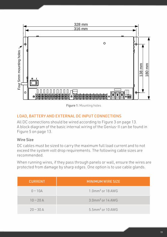
Figure 1: Mounting holes
Four
5m
m m
ounting h
ole
s
328 mm316 mm
13
8 m
m
180
mm
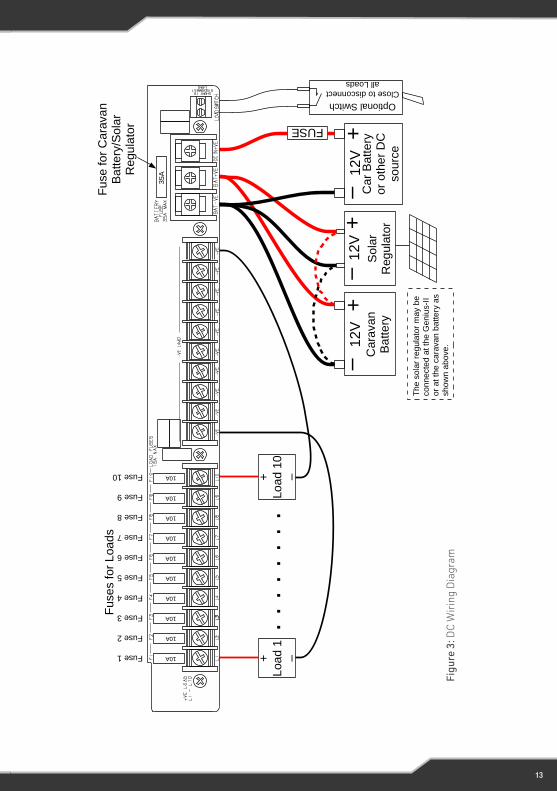
LOAD, BATTERY AND EXTERNAL DC INPUT CONNECTIONSAll DC connections should be wired according to Figure 3 on page 13. A block diagram of the basic internal wiring of the Genius-II can be found in Figure 5 on page 13.
Wire SizeDC cables must be sized to carry the maximum full load current and to not exceed the system volt drop requirements. The following cable sizes are recommended.
When running wires, if they pass through panels or wall, ensure the wires are protected from damage by sharp edges. One option is to use cable glands.
CURRENT MINIMUM WIRE SIZE
0 — 10A 1.0mm² or 18 AWG
10 — 20 A 3.0mm² or 14 AWG
20 — 30 A 5.5mm² or 10 AWG
12
Load Connections
Up to 10 independently-fused loads may beconnected. Loads are attached using the two 10-wayterminal blocks.
Refer to Table 2 for wire size recommendations.
Where the wires connect to the terminal blocks, theyshould preferably be fitted with a spade terminal. Inorder to fit into the terminal block, spade terminalsneed to conform to the dimensions provided inFigure 2.
Caravan Battery Connection
Connect the caravan battery to the terminals shown in Figure 3 on page 11.
Refer to Table 2 for wire size recommendations.
The positive connection has an on-board fuse so no additional fusing is required.
External DC Input Connection
CAUTION: Suitable fuse protection must be provided for the “DC In +VE” input. A fuse rating not exceeding 30 Amps must be used.
The power supply terminal “DC In +VE” provides an alternative option for powering of the load and charging of the batteries when mains voltages are not present. This input is to be powered from a suitable +12 V system (e.g. your Car). The voltage of this external DC power source should not exceed 14.8 V.
This input is diode isolated, so it is strictly an input; the Genius-II will never supply current to anything connected to this terminal.
This is the preferred input for a car battery connection.
Note: The Genius-II does not provide battery charging management when operating in this configuration (no mains, DC power provided through the externalinput). In this configuration current and voltage control for the battery must be provided from the external source.
Solar Panel Connection
CAUTION: Solar panels should not be directly connected; a solar panel voltage regulator must be fitted between solar panels and the battery.
Solar power should (through a series voltage regulator) be connected directly intothe caravan battery circuit. See Figure 3 on page 11.
The solar power may be wired directly to the caravan battery, or to the caravan
9
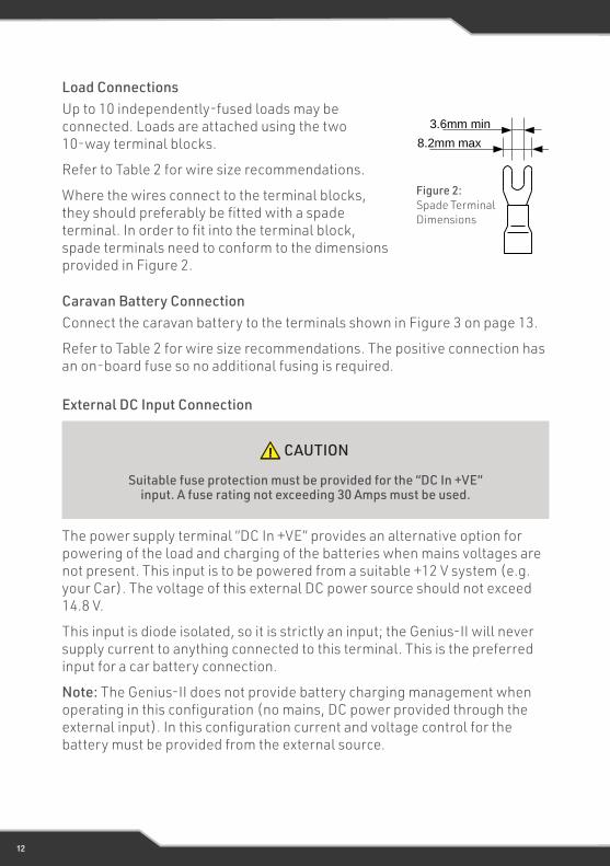
Figure 2: Spade TerminalDimensions
8.2mm max
3.6mm min
Load ConnectionsUp to 10 independently-fused loads may be connected. Loads are attached using the two 10-way terminal blocks.
Refer to Table 2 for wire size recommendations.
Where the wires connect to the terminal blocks, they should preferably be fitted with a spade terminal. In order to fit into the terminal block, spade terminals need to conform to the dimensions provided in Figure 2.
The power supply terminal “DC In +VE” provides an alternative option for powering of the load and charging of the batteries when mains voltages are not present. This input is to be powered from a suitable +12 V system (e.g. your Car). The voltage of this external DC power source should not exceed 14.8 V.
This input is diode isolated, so it is strictly an input; the Genius-II will never supply current to anything connected to this terminal. This is the preferred input for a car battery connection.
Note: The Genius-II does not provide battery charging management when operating in this configuration (no mains, DC power provided through the external input). In this configuration current and voltage control for the battery must be provided from the external source.
Figure 2: Spade Terminal Dimensions
Caravan Battery ConnectionConnect the caravan battery to the terminals shown in Figure 3 on page 13.
Refer to Table 2 for wire size recommendations. The positive connection has an on-board fuse so no additional fusing is required.
CAUTION
Suitable fuse protection must be provided for the “DC In +VE” input. A fuse rating not exceeding 30 Amps must be used.
External DC Input Connection
13
11
Fig
ure
3:
DC
Wirin
g D
iag
ram
Cara
va
nB
atte
ry
–+
12V
FUSE
+L
oa
d 1
–
Optional Switch
Close to disconnect all Loads
Fu
se
fo
r C
ara
va
n
Ba
tte
ry/S
ola
r R
egu
lato
r
+Lo
ad 1
0–
. . .
. . .
. .
Fuse 1
Fuse 2
Fuse 3
Fuse 4
Fuse 5
Fuse 6
Fuse 7
Fuse 8
Fuse 9
Fuse 10
Fuse
s f
or
Loa
ds
+– 1
2V
So
lar
Reg
ula
tor
Car
Batt
ery
or
oth
er
DC
so
urc
e
–+
12
V
10A
10A
10A
10A
10A
10A
10A
10A
10A
10A
35A
The s
ola
r re
gula
tor
may b
e
connecte
d a
t th
e G
eniu
s-I
I or
at th
e c
ara
van b
attery
as
show
n a
bove.
Figu
re 3
: DC
Wir
ing
Dia
gram
14
Solar Panel Connection
Solar power should (through a series voltage regulator) be connected directly into the caravan battery circuit. See Figure 3 on page 9. The solar power may be wired directly to the caravan battery, or to the caravan battery connections on the Genius-II. Use whichever connection point is most convenient from a wiring perspective.
Note: A solar panel voltage regulator with maximum output voltage not exceeding 14.8 V must be used at all times. In some situations the led can blink randomly, this is because the solar charger voltage is greater than the charger voltage. This occurs only when the mains and the solar charger are both present.
CAUTION
Solar panels should not be directly connected; a solar panel voltage regulator must be fitted between solar panels and the battery.
REMOTE LOAD-ISOLATOR SWITCH CONNECTIONThe Genius-II allows for remote control of the load connections. A pair of contacts are provided for connection to the external switch. When this switch is closed, all loads are disconnected from all power. Battery charging is not effected by this switch. The switch current when closed is less than 1 mA, so any convenient switch and wire size may be used.
15
Battery Connection ProcedureThe caravan battery should be connected as per the following steps.
1. Remove mains power to the Genius-II Turn off the power switch on the Genius-II
2. Disconnect all loads Turn off all 12V equipment connected to the Genius-II
3. Connect the positive battery terminal
4. Connect the negative battery terminal
If the battery negative is connected to chassis, ensure a connection exists from chassis to the “Bat—VE” terminal of the Genius-II.
WARNING
Sparks have the potential to cause an explosion should combustible gases be present. The following procedures are designed to minimise the
risk of spark generation while connecting or disconnecting the battery.
BATTERY CONNECTION/DISCONNECTION PROCEDURE
Battery Disconnection ProcedureThe caravan battery should be disconnected as per the following steps.
1. Disconnect all loads Turn off all 12V equipment connected to the Genius-II or disconnect the loads using the remove load-disconnect switch
2. Remove mains power to the Genius-II Turn off the power switch on the Genius-II
3. Disonnect the negative battery
4. Disconnect the positive battery terminal
16
(AGM) and Gel batteries.
Charge Current Battery Capacity Charging Times
15 A100 Ah 8 hours
200 Ah 16 hours
30 A
100 Ah 4 hours
200 Ah 8 hours
300 Ah 12 hours
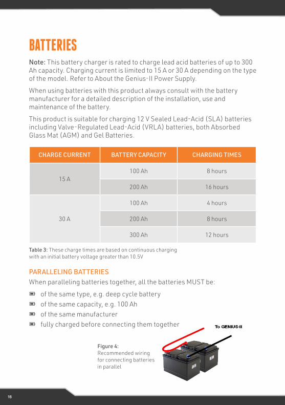
Table 3: These charge times are based on continuous charging with an initialbattery voltage greater than 10.5 V.
Paralleling Batteries
When paralleling batteries together, all the batteries MUST be
• of the same type, e.g. deep cycle battery
• of the same capacity, e.g. 100 Ah
• of the same manufacturer
• fully charged before connecting them together
WARNING: Do not install battery in same compartment where flammable material such as petrol is stored.
Storage
If the caravan is to be stored for a long period of time, first fully charge the battery and ensure all loads are disconnected. Recharge the battery at least once every 6 months. Regular recharging will prevent the battery from becoming deeply
13
Figure 4: Recommended wiring forconnecting batteries in parallel.
Table 3: These charge times are based on continuous charging with an initial battery voltage greater than 10.5V
CHARGE CURRENT BATTERY CAPACITY CHARGING TIMES
15 A100 Ah 8 hours
200 Ah 16 hours
30 A
100 Ah 4 hours
200 Ah 8 hours
300 Ah 12 hours
PARALLELING BATTERIESWhen paralleling batteries together, all the batteries MUST be:
9 9 of the same type, e.g. deep cycle battery9 9 of the same capacity, e.g. 100 Ah9 9 of the same manufacturer9 9 fully charged before connecting them together
Figure 4: Recommended wiring for connecting batteries in parallel
BATTERIESNote: This battery charger is rated to charge lead acid batteries of up to 300 Ah capacity. Charging current is limited to 15 A or 30 A depending on the type of the model. Refer to About the Genius-II Power Supply.
When using batteries with this product always consult with the battery manufacturer for a detailed description of the installation, use and maintenance of the battery.
This product is suitable for charging 12 V Sealed Lead-Acid (SLA) batteries including Valve-Regulated Lead-Acid (VRLA) batteries, both Absorbed Glass Mat (AGM) and Gel Batteries.
17
STORAGEIf the caravan is to be stored for a long period of time, first fully charge the battery and ensure all loads are disconnected. Recharge the battery at least once every 6 months. Regular recharging will prevent the battery from becoming deeply discharged—a condition which can significantly shorten battery life.
DEEPLY DISCHARGED BATTERIESThis battery charger is not designed to charge deeply discharged batteries. Its effectiveness in charging such a battery is a function of the depth of discharge and the battery size. Bigger (higher capacity) batteries will be more troublesome in this respect.
In normal use a battery connected to the Genius-II should never become deeply discharged, so recharging it should never be a problem.
If a battery has become deeply discharged and the Genius-II will not charge it, remove the battery (see Battery Connection/Disconnection Procedure on page 10) and charge it with a stand-alone charger. Once the battery voltage has recovered to normal levels and the charge current is less than 15 A, it may be reinstalled.
WARNING
Do not install battery in the same compartment where flammable material such as petrol is stored.
18
SERVICINGThis product contains hazardous voltages and energy hazards, which can result in death or injury. Only properly qualified service personnel may service it.
There are no internal user serviceable parts. Only the fuses located in the exposed terminal block area are user serviceable.
Isolate mains power, batteries and other DC input sources before servicing.
Fuses: Only the DC output load and battery fuses may be replacedFuse ratings: Loads: 32 V Automotive mini-blade Fuse, 15A maximumBattery: 32 V Automotive regular blade Fuse, 35A maximum
Factory-fitted FuseLoad fuses: 10 A FuseBattery fuse: 35 A Fuse
FUNCTIONAL DESCRIPTIONFUNCTIONAL DIAGRAMFunctional Description
Functional Diagram
AC/DC Power Supply
This provides an isolated 13.65 V DC output for powering of the load and charging of the battery. Battery current is sensed and monitored by the power supply to limit the charging current to 15 A or 30 A maximum depending on the model. Refer to About the Genius-II Power Supply.
Fault Protection
The power supply provides automatic protection for overload including short circuit, over-voltage, over-temperature and reverse connected battery.
In overload, short circuit, and over voltage condition the power supply will shut down. It will then automatically attempt to restart every 5 seconds until such case that the fault is removed.
Fusing
Each load circuit and the caravan battery connection have been fused to provide fault protection and discrimination. Refer to the servicing section for fuse ratings.
Battery Charging Features
The power supply (Genius-II) provides full battery management as per the
15
Figure 5: Functional Schematic
AC Input
Isense
10 x LoadOutputs
Caravan Battery
AC / DC
Vadj
Battery Low-voltageDisconnect Circuit
Load Remote-disconnect Circuit
Remote Load on/off Input
Battery –Ve
ReverseBattery
Protection
3.3mΩ
10 x LoadReturns
Car Battery
BAT –VE
BAT +VE
DC IN+VE
–VE
L1 – L10
LOAD SWITCH
BATERY FUSE
LOAD FUSES
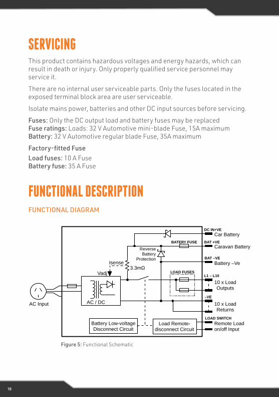
Figure 5: Functional Schematic
19
AC/DC POWER SUPPLYThis provides an isolated 13.65 V DC output for powering of the load and charging of the battery. Battery current is sensed and monitored by the power supply to limit the charging current to 15 A or 30 A maximum depending on the model. Refer to About the Genius-II Power Supply.
FAULT PROTECTIONThe power supply provides automatic protection for overload including short circuit, over-voltage, over-temperature and reverse connected battery.
In overload, short circuit, and over voltage condition the power supply will shut down. It will then automatically attempt to restart every 5 seconds until such case that the fault is removed.
FUSINGEach load circuit and the caravan battery connection have been fused to provide fault protection and discrimination. Refer to the servicing section for fuse ratings.
BATTERY CHARGING FEATURESThe power supply (Genius-II) provides full battery management as per the following: The power supply is a three stage battery charger with Boost, Float, and Store charging modes to ensure long battery life. Charging current is limited to a maximum of 15 A or 30 A maximum depending on the model. Details of the charging process can be found in the Battery Charging Management section below.
The power supply is able to deliver 35 A maximum to the battery and loads on all models. For GENIUS-II, GENIUS-IIA and GENIUS-IIN, the 15 A battery charging rate is only possible if the load current is 20A or less. If the load current exceeds 20 A, the maximum battery charging current will be reduced accordingly. The same logic goes for GENIUS-IIH, GENIUS-IIHA and GENIUS-IIHN models, but have maximum battery charge current of 30 A.
Note that for the Genius-II to operate in the manner described above, all loads must be connected to load terminals, not directly to the caravan battery.
Low Voltage Disconnection of the batteries is provided to prevent deep discharge of the battery. Automatic reconnection occurs when battery voltage recovers. Battery Current Drain is less than 3 mA.
20
Figure 6: Charging Algorithm
Charging Algorithm
Float Mode Store Mode Periodic Boost Mode
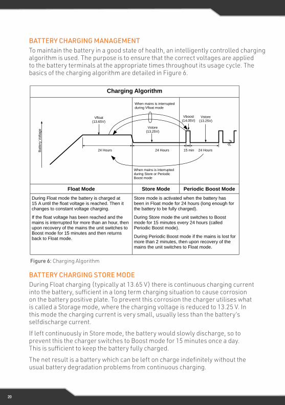
During Float mode the battery is charged at 15 A until the float voltage is reached. Then it changes to constant voltage charging.
If the float voltage has been reached and the mains is interrupted for more than an hour, then upon recovery of the mains the unit switches to Boost mode for 15 minutes and then returns back to Float mode.
Store mode is activated when the battery has been in Float mode for 24 hours (long enough for the battery to be fully charged).
During Store mode the unit switches to Boost mode for 15 minutes every 24 hours (called Periodic Boost mode).
During Periodic Boost mode if the mains is lost for more than 2 minutes, then upon recovery of the mains the unit switches to Float mode.
Figure 6: Charging Algorithm
Battery Charging Store Mode
During Float charging (typically at 13.65 V) there is continuous charging current into the battery, sufficient in a long term charging situation to cause corrosion on the battery positive plate. To prevent this corrosion the charger utilises what is called a Storage mode, where the charging voltage is reduced to 13.25 V. In this mode the charging current is very small, usually less than the battery's self-discharge current.
If left continuously in Store mode, the battery would slowly discharge, so to prevent this the charger switches to Boost mode for 15 minutes once a day. This is sufficient to keep the battery fully charged.
The net result is a battery which can be left on charge indefinitely without the usual battery degradation problems from continuous charging.
17
When mains is interrupted during Vfloat mode
When mains is interrupted
during Store or Periodic Boost mode
15 min 24 Hours24 Hours
Vfloat (13.65V)
Vstore (13.25V)
Vboost
(14.05V)
Vstore (13.25V)
24 HoursBa
ttery
Voltag
e
BATTERY CHARGING STORE MODEDuring Float charging (typically at 13.65 V) there is continuous charging current into the battery, sufficient in a long term charging situation to cause corrosion on the battery positive plate. To prevent this corrosion the charger utilises what is called a Storage mode, where the charging voltage is reduced to 13.25 V. In this mode the charging current is very small, usually less than the battery’s selfdischarge current.
If left continuously in Store mode, the battery would slowly discharge, so to prevent this the charger switches to Boost mode for 15 minutes once a day. This is sufficient to keep the battery fully charged.
The net result is a battery which can be left on charge indefinitely without the usual battery degradation problems from continuous charging.
BATTERY CHARGING MANAGEMENTTo maintain the battery in a good state of health, an intelligently controlled charging algorithm is used. The purpose is to ensure that the correct voltages are applied to the battery terminals at the appropriate times throughout its usage cycle. The basics of the charging algorithm are detailed in Figure 6.
21
LED Indicator
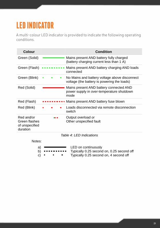
A multi-colour LED indicator is provided to indicate the following operating conditions:
Colour Condition
Green (Solid) Mains present AND battery fully charged(battery charging current less than 1 A)
Green (Flash) Mains present AND battery charging AND loads connected
Green (Blink) No Mains and battery voltage above disconnect voltage (the battery is powering the loads)
Red (Solid) Mains present AND battery connected AND power supply in over-temperature shutdown mode
Red (Flash) Mains present AND battery fuse blown
Red (Blink) Loads disconnected via remote disconnection switch
Red and/or Green flashesof unspecifiedduration
Output overload orOther unspecified fault
Table 4: LED Indications
Notes:
a) LED on continuouslyb) Typically 0.25 second on, 0.25 second offc) Typically 0.25 second on, 4 second off
18
LED INDICATORA multi-colour LED indicator is provided to indicate the following operating conditions.
22
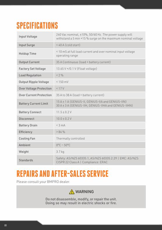
Input Voltage 240 Vac nominal, ±10%, 50/60 Hz. The power supply will withstand a 5 min +15 % surge on the maximum nominal voltage
Input Surge < 40 A (cold start)
Holdup Time < 10 mS at full load current and over nominal input voltage operating range
Output Current 35 A Continuous (load + battery current)
Factory Set Voltage 13.65 V +/0.1 V (Float voltage)
Load Regulation < 2 %
Output Ripple Voltage < 150 mV
Over Voltage Protection < 17 V
Over Current Protection 35 A to 38 A (load + battery current)
Battery Current Limit 15 A ± 1 A (GENIUS-II, GENIUS-IIA and GENIUS-IIN) 30 A ± 3 A (GENIUS-IIH, GENIUS-IIHA and GENIUS-IIHN)
Battery Connect 11.5 ± 0.2 V
Disconnect 10.0 ± 0.2 V
Battery Drain < 3 mA
Efficiency > 84 %
Cooling Fan Thermally controlled
Ambient 0°C – 50°C
Weight 3.7 kg
Standards Safety: AS/NZS 60335.1, AS/NZS 60335.2.29 | EMC: AS/NZS CISPR 22 Class A | Compliance: ERAC
SPECIFICATIONS
REPAIRS AND AFTER-SALES SERVICEPlease consult your BMPRO dealer.
WARNING
Do not disassemble, modify, or repair the unit. Doing so may result in electric shocks or fire.

23
Registering your BMPRO product is an important step to ensure that you receive all of the benefits you are entitled to. Please visit www.teambmpro.com to complete the online registration form for your new product today.
1. BMPRO goods come with guarantees that cannot be excluded under Australian Consumer Law. You are entitled to a replacement or refund for major failure and for compensation for any reasonably foreseeable loss or damage. You are entitled to have the goods repaired or replaced if the goods fail to be of acceptable quality and the failure does not amount to a major failure. The benefits under this Warranty are in addition to your other rights and remedies under a law in relation to the goods to which this Warranty relates (Australian Consumer Law).
2. BMPRO warrants products against defects for a period of two years, commencing from the original date of purchase. Proof of purchase is required before you can make a claim under this warranty.
HOW TO PROTECT YOUR RIGHTS UNDER THIS WARRANTY:
3. The GENIUS II is designed to be installed by a suitably qualified installer. You or your installer should carefully inspect the product before installation for any visible manufacturing defects. We accept no responsibility in addition to our consumer guarantee obligations where a product has been installed incorrectly.
4. This warranty does not extend to product failures or defects caused by, or associated with, but not limited to: failure to install or maintain correctly, unsuitable physical or operating environment, accident, acts of God, hazard, misuse, unauthorised repair, modification or alteration, natural disaster, corrosive environment, insect or vermin infestation and failure to comply with any additional instructions supplied with the product.
5. BMPRO may seek reimbursement of any costs incurred by BMPRO when a product is found to be in proper working order or damaged as a result of any of the warranty exclusions mentioned in point 4 of this statement.
6. To enquire or make a claim under this warranty, please follow these steps:
a) Prior to returning a BMPRO product, please email [email protected] to obtain a Return Material Authorisation (RMA) number
b) Package and send the product to:BMPRO Warranty Department 19 Henderson Road Knoxfield, VIC 3180
Please mark RMA details on the outside of the packaging
c) Please ensure the package also includes: a copy of the proof of purchase, a detailed description of the fault and your contact details including phone number and return address.
7. BMPRO will not be liable for any costs, charges or expenses incurred in the process of returning a product in order to initiate a warranty claim
WARRANTY TERMS AND CONDITIONS

TEAMBMPRO
.COM
POW
ERIN
G YO
UR A
DVEN
TURE
S.
BMPRO+61 3 9763 0962 | [email protected] 19 Henderson Rd, Knoxfield VIC 3180 Australia teambmpro.com