Embed Size (px)
Citation preview
Improper installation, adjustment, alteration, service or maintenance can cause personal injury or property damage. Refer to this manual. For assistance or additional information, contact a qualified installer, service agency, or the LP gas supplier.
FOR YOUR SAFETY Do not store or use gasoline or other flammable vapors and liquid in the vicinity of this or any other appliance.
FOR YOUR SAFETYIf you smell gas:
1. Open windows.2. Don’t touch electrical switches.3. Extinguish any open flame.4. Immediately call your gas supplier.
Thetford Customer Support Telephone: (61) 03-9358-0700
Fax: (61) 03-9357-7060Web Site: www.thetford.com.au
Part No. 636586D (1/17/2017)
Installation ManualFor Australian refrigerator models:
N314E.3F (93 liter 3-way operation with LP gas, 240 volts AC, or 12 volts DC )
N414E.3F (128 liter 3-way operation with LP gas, 240 volts AC, or 12 volts DC )
N514E.3F (164 liter 3-way operation with LP gas, 240 volts AC, or 12 volts DC )
DO NOT install this refrigerator in below deck marine applications. Do not install this refrigerator in fixed indoor cabin or other dwelling applications. This refrigerator must use only Thetford designed and approved outside air intake and exhaust ventilation for correct and safe operation. Any other ventilation could cause lethal combustion exhaust fumes and/or explosive LP gas fumes to be in the living area and/or to be below deck.
Thetford Australia41 Lara WayCampbellfield, VIC 3061
WARNING!
WARNING!
More information https://www.caravansplus.com.au
Installation Manual 2
Table of Contents
Safety Instructions
Safety Awareness
Safety Awareness .....................................................................................................................................................................................2Safety Instructions ....................................................................................................................................................................................2Certification and Code Requirements.......................................................................................................................................................3Ventilation Requirements..........................................................................................................................................................................3Assemble the Enclosure ...........................................................................................................................................................................4Install the Upper and Lower Vents............................................................................................................................................................4Install the Refrigerator ..............................................................................................................................................................................7Installation Options ...................................................................................................................................................................................7 Install the decorative door panel .......................................................................................................................................................7 Reverse the door swing.....................................................................................................................................................................8 Change the travel latch position ........................................................................................................................................................9Connect the Electrical Components .........................................................................................................................................................9 Connect the 240 volt AC supply ......................................................................................................................................................10 Connect the 12 volt DC supply ........................................................................................................................................................10Connect the LP Gas Components .......................................................................................................................................................... 11 Connect the LP gas supply system ................................................................................................................................................. 11 Connect the LP gas supply line to the refrigerator .......................................................................................................................... 11 Examine the LP gas supply system for leaks .................................................................................................................................. 11Operation Check.....................................................................................................................................................................................12Troubleshooting Refrigerator Problems ..................................................................................................................................................12
Read this manual carefully and understand the contents before you install the refrigerator.
Be aware of possible safety hazards when you see the safety alert symbol on the refrigerator and in this manual. A signal word follows the safety alert symbol and identifies the danger of the hazard. Carefully read the descriptions of these signal words to fully know their meanings. They are for your safety.
This signal word means a hazard which, if ignored, can cause dangerous personal injury, death, or much property damage.
This signal word means a hazard which, if ignored, can cause small personal injury or much property damage.
- This refrigerator is made for use in Recreational Vehicle and towable applications, and is correct for camping use. It is made to operate with, and be connected to, multiple energy sources. Disconnect all energy sources before you remove the refrigerator or do servicing to the refrigerator.
- This refrigerator is not approved for use as a free standing refrigerator. It is equipped for the use of LP gas only and can not be changed to use natural gas.
- Incorrect installation, adjustment, alteration, or maintenance of this refrigerator can cause personal injury, property damage, or both.
- Obey the instructions in this manual to install the intake and exhaust vents.
- Do not install the refrigerator directly on carpet. Put the refrigerator on a metal or wood panel that extends the full width and depth of the refrigerator.
- Do not allow anything to touch the refrigerator cooling system.
WARNING!
WARNING!
CAUTION!
More information https://www.caravansplus.com.au
Installation Manual 3
- LP gas can ignite and cause an explosion that can result in property damage, personal injury, or death. Do not smoke or create sparks. Do not use an open flame to examine the LP gas supply line for leaks. Always use two wrenches to tighten or loosen the LP gas supply line connections.
- Make sure the electrical installation obeys all applicable codes. See “Certification and Code Requirements” section.
- Do not bypass or change the refrigerator’s electrical components or features.
- Do not spray liquids near electrical outlets, connections, or the refrigerator components. Many liquids are electrically conductive and can cause a shock hazard, electrical shorts, and in some cases fire.
- The refrigerator cooling system is under pressure. Do not try to repair or to recharge a defective cooling system. The cooling system contains sodium chromate. The breathing of certain chromium compounds can cause cancer. The cooling system contents can cause severe skin and eye burns, and can ignite and burn with an intense flame. Do not bend, drop, weld, move, drill, puncture, or hit the cooling system.
- The rear of the refrigerator has sharp edges and corners. To prevent cuts or abrasions when working on the refrigerator, use caution and wear cut resistant gloves.CAUTION!
Certification and Code Requirements
This refrigerator is certified under the latest edition of the Australian Gas Association Standard AS4555/AG105 and the Australian National Electric Standard for household and similar electrical appliances AS/NZS 3350.1:1994.
The refrigerator is made for installation in a caravan or a recreational vehicle. The installation must obey the requirements of this “installation Manual” for the THETFORD limited warranty to be in effect.
The installation must agree with local codes. In the absence of local codes, the installation must obey these standards:
- Gas Installations AS5601.
- National Fuel Gas Code, ANSI Z223.1 (latest edition).
- Manufactured Home Construction and Safety Standard, Title 24 CFR, Part 3280.
- Standard for Recreational Vehicles, RVIA A119.2 latest edition.
- All gas supply piping and fittings must obey local and national codes about type and size.
Ventilation Requirements
The completed installation must:
- Make sure there is sufficient intake of fresh air for combustion.
- Make sure the living space is completely isolated from the combustion system of the refrigerator.
- Make sure there is complete and unrestricted ventilation of the flue exhaust which, in gas mode, can produce carbon monoxide. The breathing of carbon monoxide fumes can cause dizziness, nausea, or in extreme cases, death.
- Make sure the refrigerator is completely isolated from its heat generating components through the correct use of baffles and panel construction.
WARNING!
More information https://www.caravansplus.com.au
Installation Manual 4
Certified installation needs one lower intake vent and one upper exhaust vent. Install the upper exhaust vent either through the roof or through the side wall of the vehicle exactly as written in this manual. Any other installation method voids both the certification and the factory warranty of the refrigerator.
The bottom of the opening for the lower intake vent, which is also the service access door, must be even with or immediately below the floor level. This allows any leaking LP gas to escape to the outside and not to collect at floor level.
While there are no maximum clearances specified for certification, the following maximum clearances are necessary for correct refrigeration:
Bottom 0 mm min. 0 mm max.
Each Side 0 mm min 3 mm max.
Top 0 mm min. 6 mm max.
Rear 0 mm min. 25 mm max.
These clearances plus the lower and upper vents cause the natural air draft that is necessary for good refrigeration. Cooler air comes in through the lower intake vent, goes up around the refrigerator coils where it removes the excess heat from the refrigerator components, and goes out through the upper exhaust vent. If this air flow is blocked or decreased, the refrigerator will not cool correctly.Assemble the Enclosure1. Make sure the enclosure is:
N314E.3F models - 756 mm high x 521 mm wide x 543 mm deep.
N414E.3F models - 929 mm high x 602 mm wide x 620 mm deep.
N514E.3F models - 1083 mm high x 602 mm wide x 620 mm deep.
2. Make sure the floor is solid and level.
- The floor must be metal or a wood panel and extend the full width and depth of the enclosure.
- The floor must be able to support the weight of the refrigerator and its contents.
3. Make sure there are no adjacent heat sources such as a furnace vent, a hot water heater vent, etc.
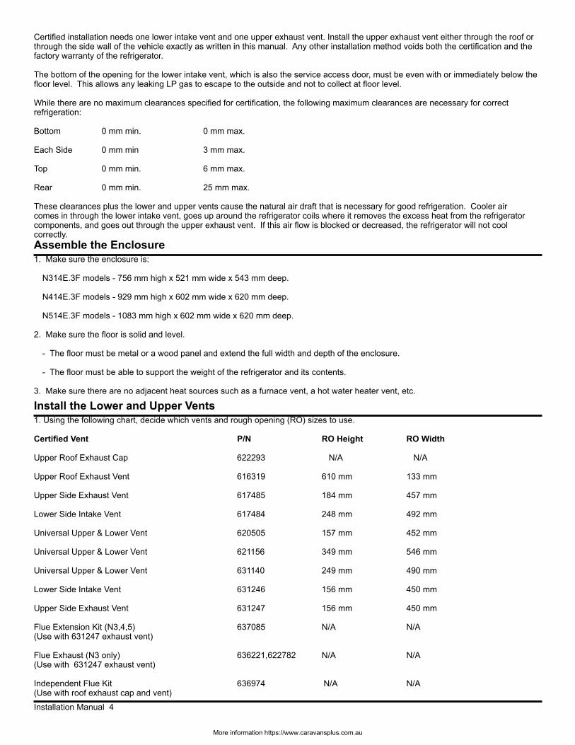
Install the Lower and Upper Vents1. Using the following chart, decide which vents and rough opening (RO) sizes to use.
Certified Vent P/N RO Height RO Width
Upper Roof Exhaust Cap 622293 N/A N/A Upper Roof Exhaust Vent 616319 610 mm 133 mm
Upper Side Exhaust Vent 617485 184 mm 457 mm Lower Side Intake Vent 617484 248 mm 492 mm
Universal Upper & Lower Vent 620505 157 mm 452 mm
Universal Upper & Lower Vent 621156 349 mm 546 mm
Universal Upper & Lower Vent 631140 249 mm 490 mm
Lower Side Intake Vent 631246 156 mm 450 mm
Upper Side Exhaust Vent 631247 156 mm 450 mm
Flue Extension Kit (N3,4,5) 637085 N/A N/A(Use with 631247 exhaust vent)
Flue Exhaust (N3 only) 636221,622782 N/A N/A(Use with 631247 exhaust vent)
Independent Flue Kit 636974 N/A N/A (Use with roof exhaust cap and vent)
More information https://www.caravansplus.com.au
Installation Manual 5
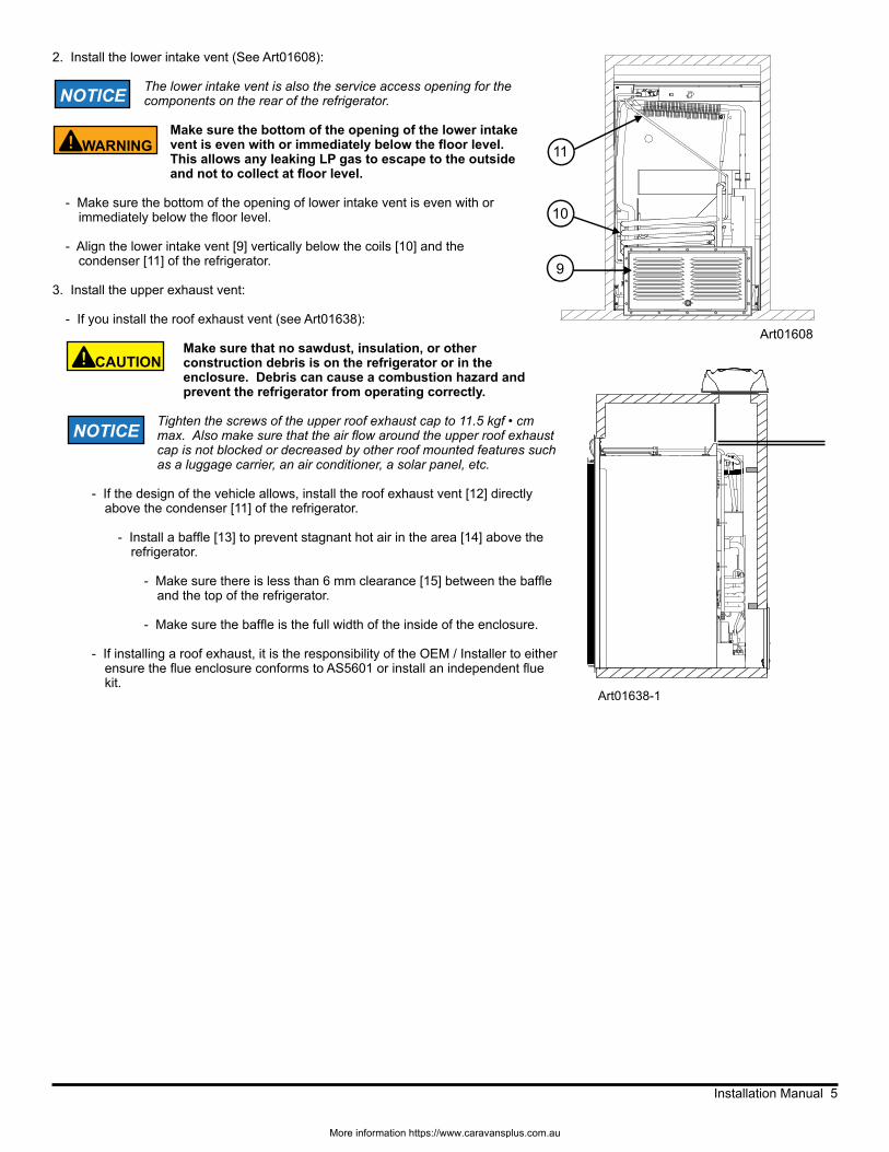
2. Install the lower intake vent (See Art01608):
The lower intake vent is also the service access opening for the components on the rear of the refrigerator.
Make sure the bottom of the opening of the lower intake vent is even with or immediately below the floor level. This allows any leaking LP gas to escape to the outside and not to collect at floor level.
- Make sure the bottom of the opening of lower intake vent is even with or immediately below the floor level.
- Align the lower intake vent [9] vertically below the coils [10] and the condenser [11] of the refrigerator.
3. Install the upper exhaust vent:
- If you install the roof exhaust vent (see Art01638):
Make sure that no sawdust, insulation, or other construction debris is on the refrigerator or in the enclosure. Debris can cause a combustion hazard and prevent the refrigerator from operating correctly.
Tighten the screws of the upper roof exhaust cap to 11.5 kgf • cm max. Also make sure that the air flow around the upper roof exhaust cap is not blocked or decreased by other roof mounted features such as a luggage carrier, an air conditioner, a solar panel, etc.
- If the design of the vehicle allows, install the roof exhaust vent [12] directly above the condenser [11] of the refrigerator.
- Install a baffle [13] to prevent stagnant hot air in the area [14] above the refrigerator.
- Make sure there is less than 6 mm clearance [15] between the baffle and the top of the refrigerator.
- Make sure the baffle is the full width of the inside of the enclosure.
- If installing a roof exhaust, it is the responsibility of the OEM / Installer to either ensure the flue enclosure conforms to AS5601 or install an independent flue kit.
Art01638-1
11
10
9
Art01608
CAUTION!
WARNING!
NOTICE
NOTICE
More information https://www.caravansplus.com.au
Installation Manual 6
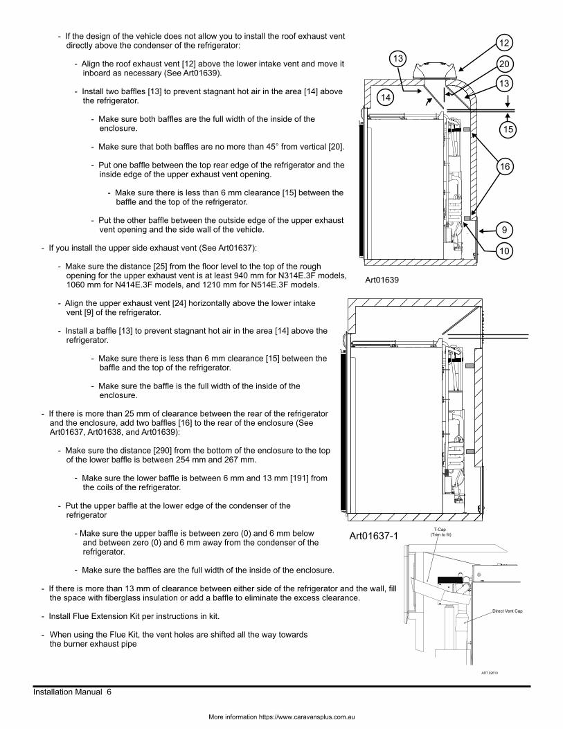
- If the design of the vehicle does not allow you to install the roof exhaust vent directly above the condenser of the refrigerator:
- Align the roof exhaust vent [12] above the lower intake vent and move it inboard as necessary (See Art01639).
- Install two baffles [13] to prevent stagnant hot air in the area [14] above the refrigerator.
- Make sure both baffles are the full width of the inside of the enclosure.
- Make sure that both baffles are no more than 45° from vertical [20].
- Put one baffle between the top rear edge of the refrigerator and the inside edge of the upper exhaust vent opening.
- Make sure there is less than 6 mm clearance [15] between the baffle and the top of the refrigerator.
- Put the other baffle between the outside edge of the upper exhaust vent opening and the side wall of the vehicle.
- If you install the upper side exhaust vent (See Art01637):
- Make sure the distance [25] from the floor level to the top of the rough opening for the upper exhaust vent is at least 940 mm for N314E.3F models, 1060 mm for N414E.3F models, and 1210 mm for N514E.3F models.
- Align the upper exhaust vent [24] horizontally above the lower intake vent [9] of the refrigerator.
- Install a baffle [13] to prevent stagnant hot air in the area [14] above the refrigerator.
- Make sure there is less than 6 mm clearance [15] between the baffle and the top of the refrigerator.
- Make sure the baffle is the full width of the inside of the enclosure.
- If there is more than 25 mm of clearance between the rear of the refrigerator and the enclosure, add two baffles [16] to the rear of the enclosure (See Art01637, Art01638, and Art01639):
- Make sure the distance [290] from the bottom of the enclosure to the top of the lower baffle is between 254 mm and 267 mm.
- Make sure the lower baffle is between 6 mm and 13 mm [191] from the coils of the refrigerator.
- Put the upper baffle at the lower edge of the condenser of the refrigerator
- Make sure the upper baffle is between zero (0) and 6 mm below and between zero (0) and 6 mm away from the condenser of the refrigerator.
- Make sure the baffles are the full width of the inside of the enclosure.
- If there is more than 13 mm of clearance between either side of the refrigerator and the wall, fill the space with fiberglass insulation or add a baffle to eliminate the excess clearance.
- Install Flue Extension Kit per instructions in kit.
- When using the Flue Kit, the vent holes are shifted all the way towards the burner exhaust pipe
14
13
12
13
16
10
Art01639
15
20
9
Art01637-1
Direct Vent Cap
T-Cap(Trim to fit)
ART 02610
More information https://www.caravansplus.com.au

Installation Manual 7
- If the construction of the vehicle does not allow the distance [25] to be 940mm for N314E.3F models, the distance can be as little as 739mm (see Art02422) if you:
- Add two baffles [17] to the rear of the enclosure:
- Make sure the distance [290] from the bottom of the enclosure to the top of the lower baffle is between 254 and 267mm.
- Put the upper baffle at the lower edge of the condenser of the refrigerator
- Make sure the upper baffle is between zero (0) and 6mm [15] below and zero (0) and 6mm away from the condenser of the refrigerator.
- Make sure the baffles are the full width of the inside of the enclosure.
- Install 636221 and 622782 as shown for the flue exhaust. 622782 may be cut off to fit over 636221.(See Art02610)
Art02422
13
17
25
14
17
15
290
191
11
Install the Refrigerator
Put the refrigerator into position (see Art01288):
Make sure the combustion seal [28] is not broken, is completely around the refrigerator mounting flanges [156], and is between the mounting flanges and the wall of the enclosure. If the combustion seal is not complete, exhaust fumes can be present in the living area of the vehicle. The breathing of exhaust fumes can cause dizziness, nausea, or in extreme cases, death.
- On N414E.3F and N514E.3F models, remove the door from the refrigerator (See “Reverse the door swing” section).
- Put screws through the holes of the refrigerator mounting flanges and into the enclosure wall.
To avoid bending the breaker, make sure that the screws are perpendicular to the breaker and do not overtighten the screws.
- Attach the door to the refrigerator.
- Put a screw through the holes [121] in the braces at the lower rear corners of the refrigerator and into the floor. Art01288
28
156121
WARNING!
NOTICE
Installation OptionsInstall the decorative door panel:
The decorative panels must be 5 mm or less in thickness.
- Make a decorative door panel [38] that is (See Art00977):
- 659 mm high x 511 mm wide for N314E.3F models.
- 787 mm high x 541 mm wide for N414E.3F models.
- 939 mm high x 541 mm wide for N514E.3F models.
- Push the decorative door panel into the slots [157] of the door end caps [158].
- Push each panel retainer [37] into the slot on the edge of the door.
NOTICE
Art0097738
15837
157
More information https://www.caravansplus.com.au
Installation Manual 8
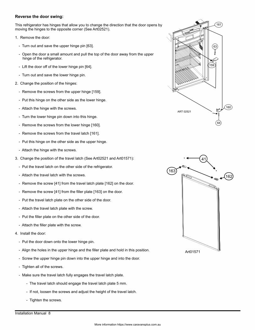
Reverse the door swing:
This refrigerator has hinges that allow you to change the direction that the door opens by moving the hinges to the opposite corner (See Art02521).
1. Remove the door:
- Turn out and save the upper hinge pin [63].
- Open the door a small amount and pull the top of the door away from the upper hinge of the refrigerator.
- Lift the door off of the lower hinge pin [64].
- Turn out and save the lower hinge pin.
2. Change the position of the hinges:
- Remove the screws from the upper hinge [159].
- Put this hinge on the other side as the lower hinge.
- Attach the hinge with the screws.
- Turn the lower hinge pin down into this hinge.
- Remove the screws from the lower hinge [160].
- Remove the screws from the travel latch [161].
- Put this hinge on the other side as the upper hinge.
- Attach the hinge with the screws.
3. Change the position of the travel latch (See Art02521 and Art01571):
- Put the travel latch on the other side of the refrigerator.
- Attach the travel latch with the screws.
- Remove the screw [41] from the travel latch plate [162] on the door.
- Remove the screw [41] from the filler plate [163] on the door.
- Put the travel latch plate on the other side of the door.
- Attach the travel latch plate with the screw.
- Put the filler plate on the other side of the door.
- Attach the filler plate with the screw.
4. Install the door:
- Put the door down onto the lower hinge pin.
- Align the holes in the upper hinge and the filler plate and hold in this position.
- Screw the upper hinge pin down into the upper hinge and into the door.
- Tighten all of the screws.
- Make sure the travel latch fully engages the travel latch plate.
- The travel latch should engage the travel latch plate 5 mm.
- If not, loosen the screws and adjust the height of the travel latch.
- Tighten the screws.
Art01571
162163
41
160
64
161
159
63
ART 02521
More information https://www.caravansplus.com.au
Installation Manual 9
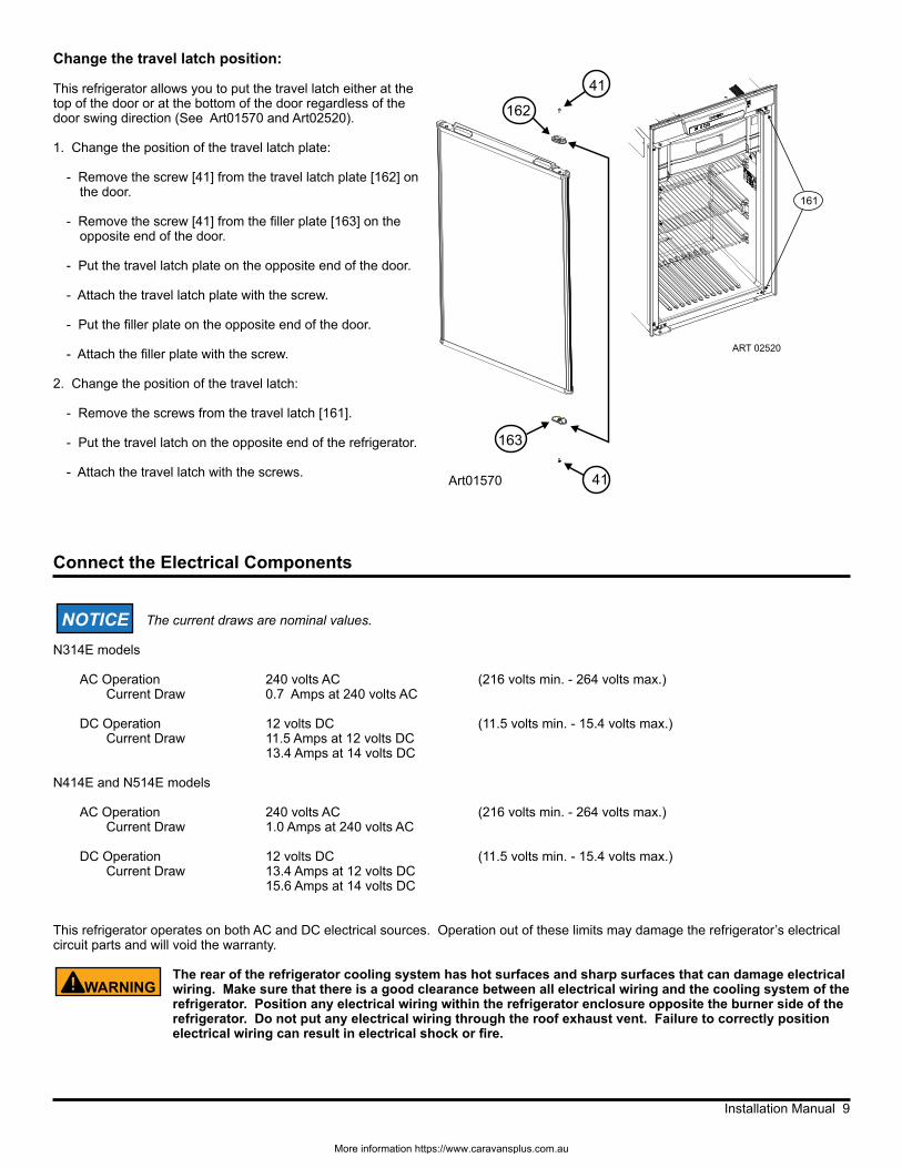
Change the travel latch position:
This refrigerator allows you to put the travel latch either at the top of the door or at the bottom of the door regardless of the door swing direction (See Art01570 and Art02520).
1. Change the position of the travel latch plate:
- Remove the screw [41] from the travel latch plate [162] on the door.
- Remove the screw [41] from the filler plate [163] on the opposite end of the door.
- Put the travel latch plate on the opposite end of the door.
- Attach the travel latch plate with the screw.
- Put the filler plate on the opposite end of the door.
- Attach the filler plate with the screw.
2. Change the position of the travel latch:
- Remove the screws from the travel latch [161].
- Put the travel latch on the opposite end of the refrigerator.
- Attach the travel latch with the screws.
Connect the Electrical Components
The current draws are nominal values.
N314E models
AC Operation 240 volts AC (216 volts min. - 264 volts max.) Current Draw 0.7 Amps at 240 volts AC
DC Operation 12 volts DC (11.5 volts min. - 15.4 volts max.) Current Draw 11.5 Amps at 12 volts DC 13.4 Amps at 14 volts DC
N414E and N514E models
AC Operation 240 volts AC (216 volts min. - 264 volts max.) Current Draw 1.0 Amps at 240 volts AC
DC Operation 12 volts DC (11.5 volts min. - 15.4 volts max.) Current Draw 13.4 Amps at 12 volts DC 15.6 Amps at 14 volts DC
This refrigerator operates on both AC and DC electrical sources. Operation out of these limits may damage the refrigerator’s electrical circuit parts and will void the warranty.
The rear of the refrigerator cooling system has hot surfaces and sharp surfaces that can damage electrical wiring. Make sure that there is a good clearance between all electrical wiring and the cooling system of the refrigerator. Position any electrical wiring within the refrigerator enclosure opposite the burner side of the refrigerator. Do not put any electrical wiring through the roof exhaust vent. Failure to correctly position electrical wiring can result in electrical shock or fire.
162
163
41
41Art01570
WARNING!
NOTICE
161
ART 02520
More information https://www.caravansplus.com.au
Installation Manual 10
Connect the 240 volt AC supply:
Connect the AC power cord only to a grounded three-prong power point. Do not remove the earth pin from the power cord. Do not use a two-prong adapter or an extension cord. Operation of the refrigerator without correct ground can cause dangerous electrical shock or death if you are touching the metal parts of the refrigerator.
Put the AC power cord into a grounded three-prong power point:
- Make sure the power point is 100-150 mm above the floor of the enclosure and is positioned within easy reach of the lower intake vent.
- Make sure the power cord does not touch the burner cover, the flue pipe, or any hot component that could damage the insulation of the power cord.
Connect the 12 volt DC supply :
As the distance from the vehicle battery to the refrigerator increases, the correct wire size and fuse size also increases. If the wire size is too small for the distance, a voltage drop occurs. The voltage drop decreases the output of the system heater and causes poor cooling performance.
1. Determine the min. wire size and the max. fuse size to use:
If you use an incorrect wire size and/or fuse size, electrical fire can result.
- Measure the distance from the vehicle battery to the refrigerator and use the following size wire and fuse:
Distance Models Min wire size Fuse size
5 m N314E.3F 4 mm² 20 Amp N414E.3F/N514E.3F 4 mm² 30 Amp
8 m N314E.3F 6 mm² 30 Amp N414E.3F/N514E.3F 6 mm² 40 Amp
- If the wire is larger than the min. size, use the correct fuse per local codes.
The wire connections must be clean, tight, and free of corrosion. If any of these items are not correct:
- A voltage drop to the refrigerator will occur.
- The voltage drop will reduce the cooling performance of the refrigerator.
The terminals for connecting the DC power supplies are marked positive (+) and ground ( ). Make sure that:
- Each DC power supply wire is attached to the correct polarity terminal.
- The chassis or the vehicle frame is not used as one of the conductors.
- The DC power supply wires including the fuses are routed directly from the battery to the refrigerator.
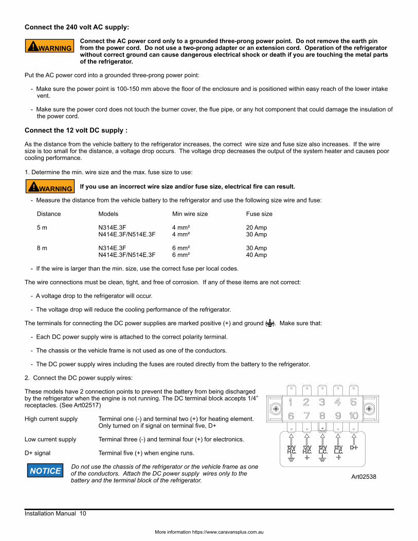
2. Connect the DC power supply wires:
These models have 2 connection points to prevent the battery from being discharged by the refrigerator when the engine is not running. The DC terminal block accepts 1/4” receptacles. (See Art02517)
High current supply Terminal one (-) and terminal two (+) for heating element. Only turned on if signal on terminal five, D+
Low current supply Terminal three (-) and terminal four (+) for electronics.
D+ signal Terminal five (+) when engine runs.
Do not use the chassis of the refrigerator or the vehicle frame as one of the conductors. Attach the DC power supply wires only to the battery and the terminal block of the refrigerator.
WARNING!
WARNING!
NOTICEArt02538
More information https://www.caravansplus.com.au
Installation Manual 11
Connect the LP Gas Components
This refrigerator operates on LP gas at a pressure of 2.7kPa LP gas. The refrigerator LP gas usage is:
N314E.3F models 1.00 MJ/h N414E.3F and N514E.3F models 1.40 MJ/h
Connect the LP gas supply system:
Be very careful when working on or near the LP gas system.
- Do not smoke or use an open flame near the LP gas system.
- Do not use an open flame to examine for leaks.
- Do not connect the refrigerator to the LP gas tank without a pressure regulator between them.
- To avoid an LP gas leak, always use two wrenches to tighten or loosen the LP gas supply line connections.
- Leaking LP gas can ignite or explode and result in dangerous personal injury or death.
Connect the LP gas supply line to the refrigerator:
- Make sure all tubing and fittings obey all local, state, and national codes about size and type.
- Use of 3/8 inch copper tubing as the LP gas supply line and a 3/8 inch SAE (UNF 5/8-18) female flare fitting as the connection to the refrigerator.
- Put the LP gas supply line up through the floor of the enclosure.
- Make sure the hole through the floor is large enough to allow clearance for the LP gas supply line.
- Put a weather resistant seal (grommet, sealant, etc.) around the LP gas supply line where it goes through the floor to prevent vibration and abrasion.
- To prevent vibration and abrasion, make sure that the LP gas supply line is not against anything in the enclosure.
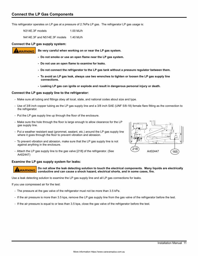
- Attach the LP gas supply line to the gas valve [218] of the refrigerator. (See Art02447)
Examine the LP gas supply system for leaks:
Do not allow the leak detecting solution to touch the electrical components. Many liquids are electrically conductive and can cause a shock hazard, electrical shorts, and in some cases, fire.
Use a leak detecting solution to examine the LP gas supply line and all LP gas connections for leaks.
If you use compressed air for the test:
- The pressure at the gas valve of the refrigerator must not be more than 3.5 kPa.
- If the air pressure is more than 3.5 kpa, remove the LP gas supply line from the gas valve of the refrigerator before the test.
- If the air pressure is equal to or less than 3.5 kpa, close the gas valve of the refrigerator before the test.
WARNING!
WARNING!
Art02447 165218
More information https://www.caravansplus.com.au
Installation Manual 12
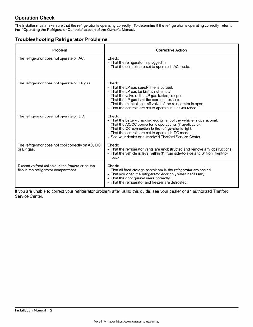
If you are unable to correct your refrigerator problem after using this guide, see your dealer or an authorized Thetford Service Center.
Operation CheckThe installer must make sure that the refrigerator is operating correctly. To determine if the refrigerator is operating correctly, refer to the “Operating the Refrigerator Controls” section of the Owner’s Manual.
Problem
The refrigerator does not operate on AC.
The refrigerator does not operate on LP gas.
The refrigerator does not operate on DC.
The refrigerator does not cool correctly on AC, DC, or LP gas.
Excessive frost collects in the freezer or on the fins in the refrigerator compartment.
Corrective Action
Check:- That the refrigerator is plugged in.- That the controls are set to operate in AC mode.
Check:- That the LP gas supply line is purged.- That the LP gas tank(s) is not empty.- That the valve of the LP gas tank(s) is open.- That the LP gas is at the correct pressure.- That the manual shut off valve of the refrigerator is open.- That the controls are set to operate in LP Gas Mode.
Check:- That the battery charging equipment of the vehicle is operational.- That the AC/DC converter is operational (if applicable).- That the DC connection to the refrigerator is tight.- That the controls are set to operate in DC mode.- See your dealer or authorized Thetford Service Center.
Check:- That the refrigerator vents are unobstructed and remove any obstructions.- That the vehicle is level within 3° from side-to-side and 6° from front-to- back.
Check:- That all food storage containers in the refrigerator are sealed.- That you open the refrigerator door only when necessary.- That the door gasket seals correctly.- That the refrigerator and freezer are defrosted.
Troubleshooting Refrigerator Problems
More information https://www.caravansplus.com.au