Embed Size (px)
Citation preview

OWNER MANUALMANUALE D’USO
DX 2006 2 IN / 6 OUT DIGITAL SIGNAL PROCESSOR PROCESSORE DIGITALE DI SEGNALE CON 2 INGRESSI E 6 USCITE
-
-


INDEXINDICE
ENGLISHSAFETY PRECAUTIONS
INSTALLATION DESCRIPTIONFRONT PANEL
REAR PANELDISPLAY ‘HOME PAGE’
INPUT / OUTPUT MENUSSYSTEM MENUSSPECIFICATIONS
ITALIANOAVVERTENZE PER LA SICUREZZA
INSTALLAZIONEDESCRIZIONE
PANNELLO FRONTALEPANNELLO POSTERIORE
SCHERMATA INIZIALE DEL DISPLAYMENÙ DEGLI INGRESSI E DELLE USCITE
MENÙ DI SISTEMADATI TECNICI
46678991418
202222232425253034
�
ENG
LISH
IMPORTANTBefore connecting and using this product, please read this instruction manual carefully and keep it on hand for future reference.The manual is to be considered an integral part of this product and must accompany it when it changes ownership as a reference for correct installation and use as well as for the safety precautions. RCF S.p.A. will not assume any responsibility for the incorrect installation and / or use of this product.
WARNING: To prevent the risk of fire or electric shock, never expose this product to rain or humidity.
SAFETY PRECAUTIONS1. All the precautions, in particular the safety ones, must be read with special attention, as they provide important information.
2. POWER SUPPLY FROM MAINSThe mains voltage is sufficiently high to involve a risk of electrocution; therefore, never install or connect this product when its power cable is plugged in.Before powering up, make sure that all the connections have been made correctly and the voltage of your mains corresponds to the voltage shown on the rating plate on the unit, if not, please contact your RCF dealer.The metallic parts of the unit are earthed by means of the power cable.An apparatus with CLASS I construction shall be connected to a mains socket outlet with a protective earthing connection.Protect the power cable from damage.Make sure it is positioned in a way that it cannot be stepped on or crushed by objects.To prevent the risk of electric shock, never open the product: there are no parts inside that the user needs to access.
3. Make sure that no objects or liquids can get into this product, as this may cause a short circuit. This apparatus shall not be exposed to dripping or splashing. No objects filled with liquid, such as vases, shall be placed on this apparatus. No naked sources (such as lighted candles) should be placed on this apparatus.
4. Never attempt to carry out any operations, modifications or repairs that are not expressly described in this manual. Contact your authorized service centre or qualified personnel should any of the following occur:
The product does not function (or functions in an anomalous way).The power supply cable has been damaged.Objects or liquids have got in the unit.The product has been subject to a heavy impact.
5. If this product is not used for a long period, disconnect the power cable.
6. If this product begins emitting any strange odours or smoke, switch it off immediately and disconnect the power supply cable.
7. Do not connect this product to any equipment or accessories not foreseen.For suspended installation, only use the dedicated anchoring points and do not try to hang this product by using elements that are unsuitable or not specific for this purpose.Also check the suitability of the support surface to which the product is anchored (wall, ceiling, structure, etc.), and the components used for attachment (screw anchors, screws, brackets not supplied by RCF etc.), which must guarantee the security of the system / installation over time, also considering, for example, the mechanical vibrations normally generated by transducers.
a.
b.
c.d.
e.f.
g.
----
IMPORTANT
WARNING
SAFETY PRECAUTIONS
�
ENG
LISH
To prevent the risk of falling equipment, do not stack multiple units of this product unless this possibility is specified in the user manual.
8. RCF S.p.A. strongly recommends this product is only installed by professional qualified installers (or specialised firms) who can ensure correct installation and certify it according to the regulations in force.The entire audio system must comply with the current standards and regulations regarding electrical systems.
9. Supports and trolleysThe equipment should be only used on trolleys or supports, where necessary, that are recommended by the manufacturer. The equipment / support / trolley assembly must be moved with extreme caution. Sudden stops, excessive pushing force and uneven floors may cause the assembly to overturn.
10. There are numerous mechanical and electrical factors to be considered when installing a professional audio system (in addition to those which are strictly acoustic, such as sound pressure, angles of coverage, frequency response, etc.).
11. Hearing lossExposure to high sound levels can cause permanent hearing loss. The acoustic pressure level that leads to hearing loss is different from person to person and depends on the duration of exposure. To prevent potentially dangerous exposure to high levels of acoustic pressure, anyone who is exposed to these levels should use adequate protection devices.When a transducer capable of producing high sound levels is being used, it is therefore necessary to wear ear plugs or protective earphones.See the technical specifications in loudspeaker instruction manuals to know their maximum sound pressure levels.
12. To prevent the occurrence of noise, use screened cables only and avoid putting them close to:
Equipment that produces high-intensity electromagnetic fields (for example, high power transformers)Mains cablesLoudspeaker lines.
13. Situate this product far from any heat sources.
14. force the control elements (keys, knobs, etc. ).
15. Do not use solvents, alcohol, benzene or other volatile substances for cleaning the external parts of this product.
-
--
�
ENG
LISH
RCF S.P.A. THANKS YOU FOR PURCHASING THIS PRODUCT, WHICH HAS BEEN DESIGNED TO GUARANTEE RELIABILITY AND HIGH PERFORMANCES.
DESCRIPTION
DX 2006 is a digital signal processor designed for loudspeaker management on touring or fixed sound systems.Its features include 2 inputs and 6 outputs, 40-bit floating point processors, high performance 24-bit converters.The unit has 30 presets to store and recall all settings.
The parameter list includes I/O levels, delay, polarity, 8-band EQ per channel, multiple crossover selections and limiters.Precise frequency control is achieved with its 1 Hz resolution.Inputs can be routed to outputs in multiple configurations.DX 2006 can be configured in real time either on its front panel or through its intuitive PC ‘XConsole’ graphic user interface (‘GUI’, via either RS-232 or USB).Future firmware upgrades (via PC) will keep the device current with newly developed algorithms and functions.
THE PACKAGE INCLUDES (besides the DX 2006 processor):User manualPC ‘Xconsole’ softwarePower cable
FEATURES:2 inputs that can be mixed to 6 outputs40-bit floating point DSP96 kHz sampling rate24-bit A/D D/A converters1 Hz frequency resolution (EQ / filters)8 equalizers for each input and outputMultiple crossover types; limitersLevel, polarity and delay settingsFirmware upgrade via PCIndividual channel buttons (for editing) with linking capability2-Line x 16 character backlit LCD display5-segment LED arrays indicating the signal levels of every input and outputStorage of up to 30 presetsSecurity Lock (with password)USB and RS232 ports for PC configuration.
---
---------------
INSTALLATION
This device can be installed into a 19” rack cabinet (1 unit) with 4 screws thanks to its rack ears.
�
ENG
LISH
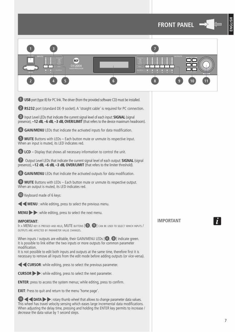
FRONT PANEL
1 USB port (type B) for PC link. The driver (from the provided software CD) must be installed.
2 RS232 port (standard DE-9 socket). A ‘straight cable’ is required for PC connection.
3 Input Level LEDs that indicate the current signal level of each input: SIGNAL (signal presence), –12 dB, –6 dB, –3 dB, OVER/LIMIT (that refers to the device maximum headroom).
4 GAIN/MENU LEDs that indicate the activated inputs for data modification.
5 MUTE Buttons with LEDs – Each button mute or unmute its respective input.When an input is muted, its LED indicates red.
6 LCD – Display that shows all necessary information to control the unit.
7 Output Level LEDs that indicate the current signal level of each output: SIGNAL (signal presence), –12 dB, –6 dB, –3 dB, OVER/LIMIT (that refers to the limiter threshold).
8 GAIN/MENU LEDs that indicate the activated outputs for data modification.
9 MUTE Buttons with LEDs – Each button mute or unmute its respective output.When an output is muted, its LED indicates red.
P Keyboard made of 6 keys:
MENU : while editing, press to select the previous menu.
MENU : while editing, press to select the next menu.
IMPORTANT:If a MENU kEy Is prEssEd aNd hEld, MUTE bUTToNs [5, 9] caN bE UsEd To sElEcT whIch INpUTs / oUTpUTs arE affEcTEd by paraMETEr valUE chaNgEs.
When inputs / outputs are editable, their GAIN/MENU LEDs [4, 8] indicate green. It is possible to link either the two inputs or more outputs for common parameter modification.It is not possible to edit both inputs and outputs at the same time, therefore first it is necessary to remove all inputs from the edit mode before adding outputs (or vice-versa).
CURSOR: while editing, press to select the previous parameter.
CURSOR : while editing, press to select the next parameter.
ENTER: press to access the system menus; while editing, press to confirm.
EXIT: Press to quit and return to the menu ‘home page’.
{ DATA : rotary thumb wheel that allows to change parameter data values.This wheel has travel velocity sensing which eases large incremental data modifications.When adjusting the delay time, pressing and holding the ENTER key permits to increase / decrease the data value by 1 second steps.
IMPORTANT
1
2
3
4 5 6 8
7
9 10 11

�
ENG
LISH
REAR PANEL
} INPUTS – Audio (analogue) balanced inputs (3-pin female XLR connectors).
q OUTPUTS – Audio (analogue) balanced outputs (3-pin male XLR connectors).
w Power connector (standard IEC socket). A compatible power cord is supplied with the unit.The operating voltage is 90 ÷ 240 V ac (50-60 Hz).
e Fuse type: T2.5A-250V.
r POWER – power switch (I : ON, O = OFF).
– ground
– hot
– cold
CABLE MALE XLR CONNECTOR PINS:
OUTPUTS INPUTS
1 2 3 4 5 6 1 2
POW ER BALANCED SIGNAL
2
3GND
AUDIO PROCESSOR
DX
12
3GND
1
INPUTSOUTPUTS
16 13
15
14 12
SHIELD
�
ENG
LISH
DISPLAY ‘HOME PAGE’
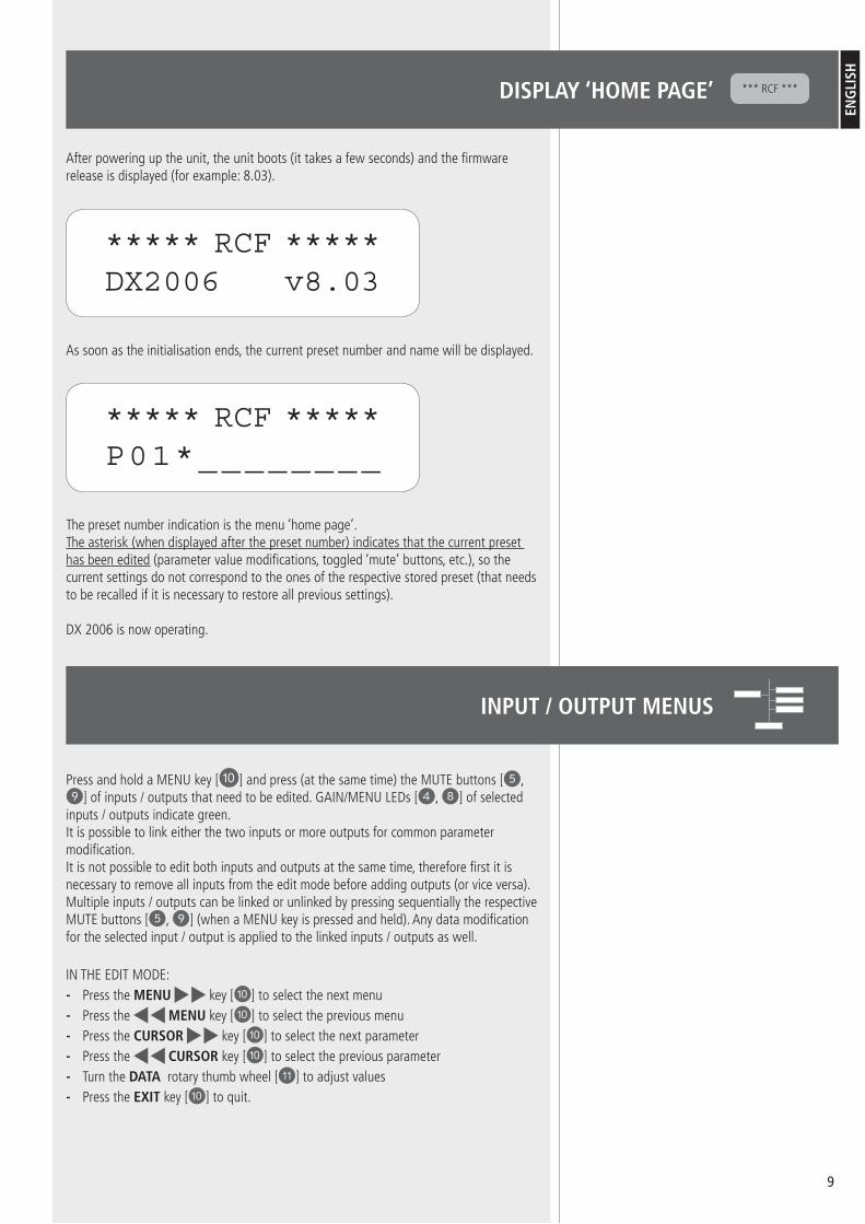
After powering up the unit, the unit boots (it takes a few seconds) and the firmware release is displayed (for example: 8.03).
As soon as the initialisation ends, the current preset number and name will be displayed.
The preset number indication is the menu ‘home page’.The asterisk (when displayed after the preset number) indicates that the current preset has been edited (parameter value modifications, toggled ‘mute’ buttons, etc.), so the current settings do not correspond to the ones of the respective stored preset (that needs to be recalled if it is necessary to restore all previous settings).
DX 2006 is now operating.
*** RCF ***
***** RCF *****DX2006 v8.03
***** RCF *****P01*________
Press and hold a MENU key [P] and press (at the same time) the MUTE buttons [5, 9] of inputs / outputs that need to be edited. GAIN/MENU LEDs [4, 8] of selected inputs / outputs indicate green. It is possible to link either the two inputs or more outputs for common parameter modification.It is not possible to edit both inputs and outputs at the same time, therefore first it is necessary to remove all inputs from the edit mode before adding outputs (or vice versa).Multiple inputs / outputs can be linked or unlinked by pressing sequentially the respective MUTE buttons [5, 9] (when a MENU key is pressed and held). Any data modification for the selected input / output is applied to the linked inputs / outputs as well.
IN THE EDIT MODE:Press the MENU key [P] to select the next menuPress the MENU key [P] to select the previous menuPress the CURSOR key [P] to select the next parameterPress the CURSOR key [P] to select the previous parameterTurn the DATA rotary thumb wheel [{] to adjust valuesPress the EXIT key [P] to quit.
------
INPUT / OUTPUT MENUS

10
ENG
LISH
THE AVAILABLE MENUS ARE: SIGNALEQ (8-band equalizer, from EQ1 to EQ8) XOVER (crossover, on outputs only)LIMIT (limiter, on outputs only)SOURCE (on outputs only)NAME
DISPLAY:
C : edited channelI1 : input 1, I2 : input 2O1 : output 1, O2 : output 2, O3 : output 3, O4 : output 4
If INpUTs / oUTpUTs arE lINkEd, aNy ModIfIcaTIoN affEcTs all of ThEM (alThoUgh ThE dIsplay INdIcaTEs oNly oNE IN ITs Top lEfT-haNd corNEr).
M : selected menu
P : selected parameter and its value
------
••
I1:_____ SignalLEVEL:0.00dB
C M
P
DISPLAY
I1:_____ SignalLEVEL:0.00dB
LEVELSignal level, range: from – 40 dB to + 15 dB (in 0.25 dB steps).
POLSignal polarity (phase) that can be normal (+) or inverted (–).Normal (+) is the suggested default setting.
ThE phasE INvErsIoN May bE UsEfUl To coMpENsaTE or MINIMIsE possIblE UNdEsIrEd acoUsTIcal dEsTrUcTIvE INTErfErENcEs, dUE To parTIcUlar loUdspEakEr posITIoNs.
DELAYSignal delay, range 0 ÷ 40 ms (in steps of ca. 10 μS; press and hold the ENTER key to increase / decrease the data value by ca. 1 second steps). It can be displayed in either milliseconds (ms) or equivalent feet (ft) or metres (m); this setting is explained in the ‘System menus’ manual section.
I1:_____ SignalPOL:+
I1:_____ SignalDELAY:000.000ms
SIGNAL MENUSIGNAL MENU

11
ENG
LISH
I1:______ EQ1EQ#:1
EQ#Selection of the band to be edited among the 8 available (EQ1 ÷ EQ8).
BYPASSThis parameter toggles the selected band bypass.If set to ON, the current band setting will not affect the signal.
TYPEIt is possible to choose among 5 different types:
parametric equalizer (PEQ)low-shelf filter (LO-SHF)hi-shelf filter (HI-SHF)first-order all-pass filter (AP-1)second-order all-pass filter (AP-2)
Parametric equalizers (PEQ) allow to adjust the level L at the settable centre frequency Fc and specify the bandwidth BW (the adjusted level can be widened or narrowed).
-----
I1:______ EQ1BYPASS:Off
I1:______ EQ1TYPE:PEQ
Low-shelf filters increase or decrease the level of all frequencies below the centre frequency by the specified amount.
Hi-shelf filters increase or decrease the level of all frequencies above the centre frequency by the specified amount.
All-pass filters pass all frequencies equally, but change the signal phase.
FREQEqualizer centre frequency setting. Its range is from 20 Hz to 30 kHz in either 1 Hz or 1/36 octave steps (the frequency steps can be chosen in the ‘System menu’, please refer to the respective manual section).
BW (PEQ, LO-SHF, HI-SHF, AP-2 filters only)Equalizer bandwidth setting.Its range is from 0.02 to 3.61 octaves in 0.01 steps.The equivalent ‘Q factor’ value is automatically displayed besides the octave value.
DEG (AP-1 filter only)If the first-order all-pass (AP-1) filter is selected, this parameter will set the phase shift degree at the centre frequency.The phase shift is gradually changed from 180 degrees to the specified value of the centre frequency.
LEVEL (PEQ, LO-SHF, HI-SHF filters only)Equalizer level setting.Its range is from –30.00 dB to +15.00 dB in 0.25 dB steps.
I1:______ EQ1FREQ:1000Hz
I1:______ EQ1BW:0.33 Q=4.36
I1:______ EQ1DEG:15.5 deg
I1:______ EQ1LEVEL:0.00dB
EQ (EQUALIZATION) MENUEQ (EQUALIZATION) MENU
PEQ

12
ENG
LISH
O1:______ XOverTYPL:Off
crossovErs arE NEEdEd To splIT ThE aUdIo sIgNal INTo sEparaTE frEqUENcy baNds (IN ordEr To gET MUlTI-way soUNd sysTEMs), whIch caN bE haNdlEd by INdIvIdUal loUdspEakErs (I.E. woofErs, MIdraNgE spEakErs, TwEETErs) dEsIgNEd for ThosE baNds.
TYPL (filter type for the band lower frequency)It allows to select the high-pass filter type among Butterworth, Linkwitz-Riley or Bessel.The OFF setting disables the high-pass filter.
FRQL (band lower frequency)
High-pass filter cut-off frequency setting.Its range is from 20 Hz to 30 kHz in either 1 Hz or 1/36 octave steps (the frequency steps can be chosen in the ‘System menu’, please refer to the respective manual section).
SLPL (filter slope for the band lower frequency)High-pass filter slope setting.The available slopes are:
From 6 dB to 48 dB, 6 dB steps, for the Butterworth and Bessel filter typesFrom 12 dB to 48 dB, 12 dB steps, for the Linkwitz-Riley filter type.
TYPH (filter type for the band upper frequency)It allows to select the low-pass filter type among Butterworth, Linkwitz-Riley or Bessel.The OFF setting disables the low-pass filter.
FRQH (band upper frequency)
Low-pass filter cut-off frequency setting.Its range is from 20 Hz to 30 kHz in either 1 Hz or 1/36 octave steps (the frequency steps can be chosen in the ‘System menu’, please refer to the respective manual section).
SLPH (filter slope for the band upper frequency) Low-pass filter slope setting.The available slopes are:
From 6 dB to 48 dB, 6 dB steps, for the Butterworth and Bessel filter typesFrom 12 dB to 48 dB, 12 dB steps, for the Linkwitz-Riley filter type.
ThE INsErTIoN of boTh hI-pass aNd low-pass fIlTErs Is a baNd-pass fIlTEr.
--
--
O1:______ XOverFRQL:1000Hz
O1:______ XOverSLPL:24dB
O1:______ XOverTYPH:Off
O1:______ XOverFRQH:1000Hz
O1:______ XOverSLPH:24dB
XOVER MENU (CROSSOVER, ON OUTPUTS ONLY)
XOVER MENU (CROSSOVER, ON OUTPUTS ONLY)
FRQL
L
F
FRQH
L
F
FRQL
L
FFRQH
13
ENG
LISH
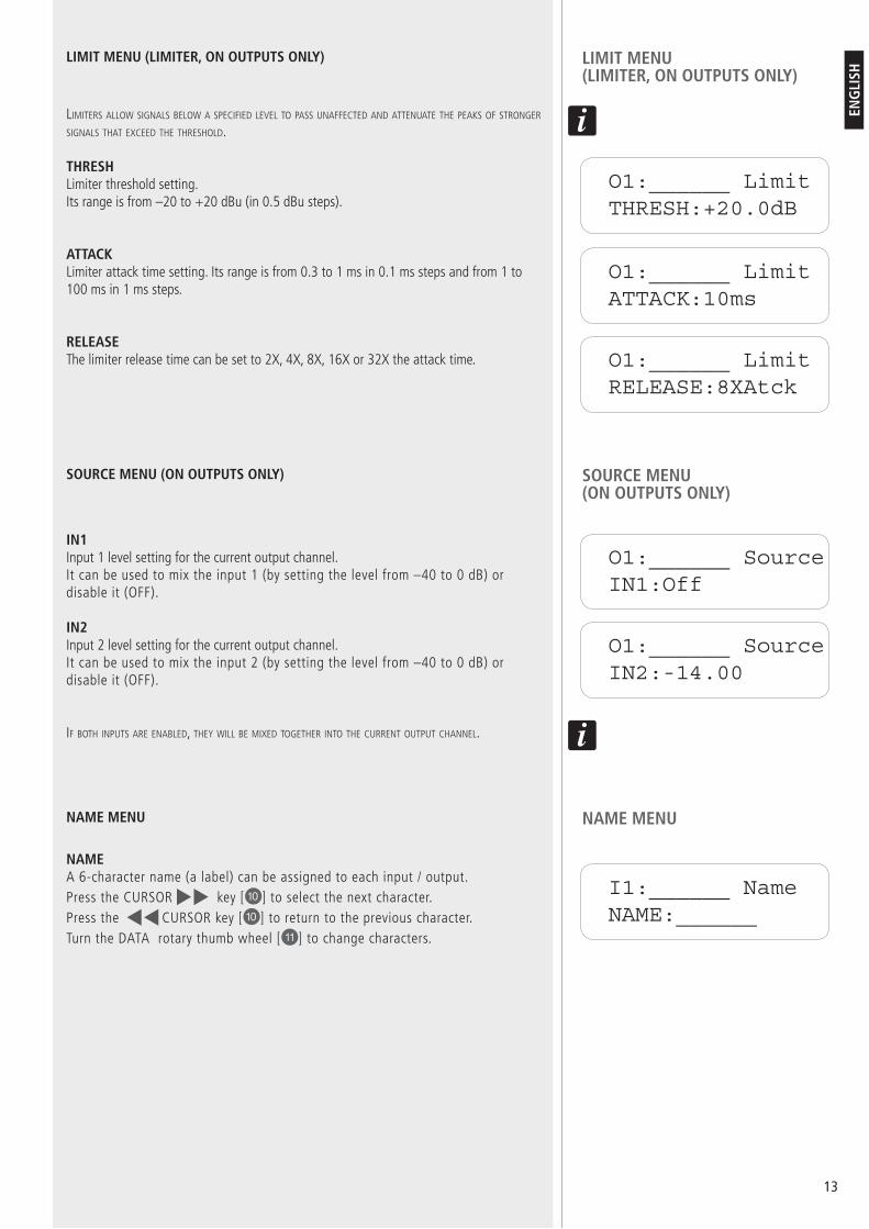
O1:______ LimitTHRESH:+20.0dB
lIMITErs allow sIgNals bElow a spEcIfIEd lEvEl To pass UNaffEcTEd aNd aTTENUaTE ThE pEaks of sTroNgEr sIgNals ThaT ExcEEd ThE ThrEshold.
THRESHLimiter threshold setting.Its range is from –20 to +20 dBu (in 0.5 dBu steps).
ATTACKLimiter attack time setting. Its range is from 0.3 to 1 ms in 0.1 ms steps and from 1 to 100 ms in 1 ms steps.
RELEASEThe limiter release time can be set to 2X, 4X, 8X, 16X or 32X the attack time.
O1:______ LimitATTACK:10ms
O1:______ LimitRELEASE:8XAtck
IN1Input 1 level setting for the current output channel.It can be used to mix the input 1 (by setting the level from –40 to 0 dB) or disable it (OFF).
IN2Input 2 level setting for the current output channel.It can be used to mix the input 2 (by setting the level from –40 to 0 dB) or disable it (OFF).
If boTh INpUTs arE ENablEd, ThEy wIll bE MIxEd TogEThEr INTo ThE cUrrENT oUTpUT chaNNEl.
O1:______ SourceIN1:Off
O1:______ SourceIN2:-14.00
NAMEA 6-character name (a label) can be assigned to each input / output.Press the CURSOR key [P] to select the next character.Press the CURSOR key [P] to return to the previous character.Turn the DATA rotary thumb wheel [{] to change characters.
I1:______ NameNAME:______
LIMIT MENU (LIMITER, ON OUTPUTS ONLY)
LIMIT MENU (LIMITER, ON OUTPUTS ONLY)
SOURCE MENU (ON OUTPUTS ONLY)
SOURCE MENU (ON OUTPUTS ONLY)
NAME MENUNAME MENU

1�
ENG
LISH
SYSTEM MENUS
The system menus allow the user to control and change parameters that are related to the unit general operation. These can be accessed by pressing the ENTER key [P] when the display shows the ‘home page’ (when no input/output menu is activated).All system menus require to press ENTER key [P] twice to confirm and save new settings.
AFTER ENTERING:Press the MENU key [P] to select the next menuPress the MENU key [P] to select the previous menuPress the CURSOR key [P] to select the next parameterPress the CURSOR key [P] to select the previous parameterTurn the DATA rotary thumb wheel [{] to adjust valuesPress the ENTER key [P] to proceed / confirmPress the EXIT key to quit.
THE AVAILABLE MENUS ARE: PRESET RECALL (‘Recall’ is displayed)PRESET STORE (‘Store’ is displayed) INPUT / OUPUT COPY (‘Copy’ is displayed) GENERAL SETTINGS (‘Generl’ is displayed)COMMUNICATION SETTINGS (‘Comm’ is displayed)SECURITY (‘Secure’ is displayed)FACTORY SETTINGS (‘Reset’ is displayed)INTERNAL SYSTEM OPTIMIZER (noise gate, ‘ISO’ is displayed) INFO
-------
---------
PRESET RECALL MENU
P:nThis parameter allows to select which preset (n) will be recalled from the internal memory.The program name is displayed beside the program number.
PRESET STORE MENU
DX 2006 has a built in non-volatile memory that can store up to 30 different presets.
A preset can be stored using this menu. The old preset having with the same number will be replaced. Once the preset is stored on the internal memory, it can be always recalled, even after powering down.
P:nThis parameter allows to select which preset (n) will be stored on the internal memory.
NAM:A descriptive name (a label) of up to 12 characters can be assigned to each preset. Press the CURSOR key [P] to select the next character.Press the CURSOR key [P] to return to the previous character.Turn the DATA rotary thumb wheel [{] to change characters.
PRESET RECALL MENU
PRESET STORE MENU
SYSTEM RecallP:1 _________
SYSTEM StoreP:1
SYSTEM StoreNAM:_________

1�
ENG
LISH
INPUT / OUPUT COPY MENU
THIS MENU ALLOWS TO COPY INPUTS / OUTPUTS:When the source and the target are both inputs, all parameter values will be copiedWhen the source and the target are both outputs, all parameters values will be copiedIf the source is an input and the target is an output (or vice-versa), ‘Level’, ‘Polarity’, ‘Delay’, ‘EQ’ and ‘Name’ will be copied only.
SOURCESource input / output from which data are copied.
TARGETTarget input / output to which data are copied.
GENERAL SETTINGS MENU
FREQ MODESetting of the frequency control mode for EQ and crossover filters.It can be either 36 steps/octave or all frequencies (1 Hz resolution).
DELAY UNITDelay unit setting: the delay can be displayed in either milliseconds (ms) or equivalent feet (ft) or metres (m).
COMMUNICATION SETTINGS MENU
NoTE: ThE UNIT NEEds To bE rEbooTEd (swITch ThE UNIT off, ThEN oN agaIN) bEforE NEw coMMUNIcaTIoN sETTINgs TakE EffEcT.
DEVICE ID This setting assigns a device ID number (from 1 to 16) to the unit. This ID is only useful when a network of more than 1 device is used. In normal operation the device ID is 1.
BAUD RATESerial communication baud rate setting.PC ‘XConsole’ uses a baud rate of 115200, so this value should be left unchanged.
SECURITY MENU
PASSWORDA new DX 2006 does not require a password.The device can be protected against unauthorized editing by a 4-character password, which can be stored when using the PC ‘Xconsole’ software only.When the correct password is entered, the parameter protection will be disabled.After re-entering the password (or turning the unit off), the parameter protection will be enabled again.Press the CURSOR key [P] to select the next character.Press the CURSOR key [P] to return to the previous character.Turn the DATA rotary thumb wheel [{] to change characters.
---
INPUT / OUPUT COPY MENU
GENERAL SETTINGS MENU
COMMUNICATION SETTINGS MENU
SECURITY MENU
SYSTEM CopySOURCE:In1
SYSTEM CopyTARGET:In2
SYSTEM GenerlFREQ MODE:All
SYSTEM GenerlDELAY UNIT:ms
SYSTEM CommDEVICE ID:1
SYSTEM CommBAUD RATE:115200
SYSTEM SecurePASSWORD:____

1�
ENG
LISH
SYSTEM ResetCURRENT:Yes
FACTORY SETTINGS MENU
RESET CURRENTIf necessary, turn the DATA rotary thumb wheel [11] to select YES, then press ENTER [10] twice to reset all current parameter values back to factory default settings.
NoTE: sTorEd prEsETs aNd sysTEM sETTINgs arE NoT affEcTEd by ThE rEsET fUNcTIoN!
aTTENTIoN: ThIs fUNcTIoN dElETEs all cUrrENT valUE chaNgEs!
INTERNAL SYSTEM OPTIMIZER MENU (NOISE GATE)
The unit features a ‘noise gate’ that reduces the ground floor noise when no signal is present on inputs.
THRESHOLDThe noise gate threshold level can be adjusted (from 80 to 120).
BYPASSIf unwanted noise gate effects are audible on low sound levels, the noise gate can be disabled by setting BYPASS to ON.
INFO MENU
NAM (name)The device name is displayed.
FIRMWAREThe firmware release is displayed.
CODEThis code is 11110000 if no security password has been set (factory setting).If this code is not 11110000, a security password has been set and parameters cannot be modified by an user that does not know the right password.
FACTORY SETTINGS MENU
INTERNAL SYSTEM OPTIMIZER MENU (NOISE GATE)
INFO MENU
SYSTEM ISOTHRESHOLD:102
SYSTEM ISOBYPASS:On
SYSTEM InfoNAM:_________
SYSTEM InfoFIRMWARE:v8.00
SYSTEM InfoCODE:11110000

1�
ENG
LISH
CHANNEL PARAMETER REFERENCE
PC SOFTWAREDX 2006 is shipped with a special PC Graphic User Interface (GUI) application, named ‘Xconsole’, which allows the user to control the unit from a PC.Presets can be recalled and stored from/to PC hard disk.DX 2006 can be linked to a PC via either RS232 or USB.USB may require the installation of additional drivers.
MENU PARAMETER MIN. VALUE MAX. VALUE STEPS UNIT
Signal
Level – 40 + 15 0.25 dB
Polarity + / –
Delay
0 40 0.010 / 0.011 mS
0 45.538 0.011 / 0.012 ft
0 13.876 0.003 / 0.004 m
Equalizer
EQ number 1 8 1
Bypass Off / On
Type PEQ / LO-SHF / HI-SHF / AP-1 / AP-2
Frequency 20 30 000 1 Hz / 1/36oct Hz / octaves
Bandwidth 0.02 3.61 0.01 octaves
Degree (AP-1) 0 179.5 0.5 degrees
Level – 30 + 15 0.25 dB
Crossover(high-pass,low-pass)
Type Off / Butterworth / Linkwitz-Riley / Bessel
Cutoff frequency 20 30 000 1 Hz / 1/36oct Hz / octaves
Slope 6 /(12 LR) 48 6 / (12 LR) dB
Limiter
Threshold – 20 + 20 0.5 dBu
Attack time 0.3 100 0.1 / 1 ms
Release time 2x / 4x / 8x / 16x / 32x Attack time
SourceInput 1 level Off / – 40 0 0.25 dB
Input 2 level Off / – 40 0 0.25 dB
Name Name 6 characters
1�
ENG
LISH
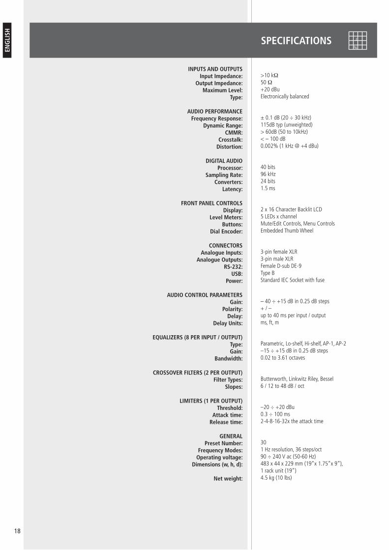
SPECIFICATIONS
INPUTS AND OUTPUTSInput Impedance:
Output Impedance: Maximum Level:
Type:
AUDIO PERFORMANCEFrequency Response:
Dynamic Range:CMMR:
Crosstalk:Distortion:
DIGITAL AUDIOProcessor:
Sampling Rate:Converters:
Latency:
FRONT PANEL CONTROLSDisplay:
Level Meters:Buttons:
Dial Encoder:
CONNECTORSAnalogue Inputs:
Analogue Outputs:RS-232:
USB:Power:
AUDIO CONTROL PARAMETERSGain:
Polarity:Delay:
Delay Units:
EQUALIZERS (8 PER INPUT / OUTPUT)Type:Gain:
Bandwidth:
CROSSOVER FILTERS (2 PER OUTPUT)Filter Types:
Slopes:
LIMITERS (1 PER OUTPUT)Threshold:
Attack time:Release time:
GENERALPreset Number:
Frequency Modes:Operating voltage:
Dimensions (w, h, d):
Net weight:
>10 kΩ50 Ω+20 dBuElectronically balanced
± 0.1 dB (20 ÷ 30 kHz)115dB typ (unweighted)> 60dB (50 to 10kHz)< – 100 dB0.002% (1 kHz @ +4 dBu)
40 bits96 kHz24 bits1.5 ms
2 x 16 Character Backlit LCD5 LEDs x channelMute/Edit Controls, Menu ControlsEmbedded Thumb Wheel
3-pin female XLR3-pin male XLRFemale D-sub DE-9Type BStandard IEC Socket with fuse
– 40 ÷ +15 dB in 0.25 dB steps+ / – up to 40 ms per input / outputms, ft, m
Parametric, Lo-shelf, Hi-shelf, AP-1, AP-2–15 ÷ +15 dB in 0.25 dB steps0.02 to 3.61 octaves
Butterworth, Linkwitz Riley, Bessel6 / 12 to 48 dB / oct
–20 ÷ +20 dBu0.3 ÷ 100 ms2-4-8-16-32x the attack time
301 Hz resolution, 36 steps/oct 90 ÷ 240 V ac (50-60 Hz)483 x 44 x 229 mm (19”x 1.75”x 9”), 1 rack unit (19”) 4.5 kg (10 lbs)


20
ITA
LIA
NO
IMPORTANTEPrima di collegare ed utilizzare questo prodotto, leggere attentamente le istruzioni contenute in questo manuale, il quale è da conservare per riferimenti futuri. Il presente manuale costituisce parte integrante del prodotto e deve accompagnare quest’ultimo anche nei passaggi di proprietà, per permettere al nuovo proprietario di conoscere le modalità d’installazione e d’utilizzo e le avvertenze per la sicurezza.L’installazione e l’utilizzo errati del prodotto esimono la RCF S.p.A. da ogni responsabilità.
ATTENZIONE: Per prevenire i rischi di fiamme o scosse elettriche, non esporre mai questo prodotto alla pioggia o all’umidità.
AVVERTENZE PER LA SICUREZZA1. Tutte le avvertenze, in particolare quelle relative alla sicurezza, devono essere lette con particolare attenzione, in quanto contengono importanti informazioni.
2. ALIMENTAZIONE DIRETTA DA RETELa tensione di alimentazione dell’apparecchio ha un valore sufficientemente alto da costituire un rischio di folgorazione per le persone: non procedere mai all’installazione o connessione dell’apparecchio con il cavo d’alimentazione collegato alla rete.Prima di alimentare questo prodotto, assicurarsi che tutte le connessioni siano corrette e che la tensione della vostra rete di alimentazione corrisponda quella di targa dell’apparecchio, in caso contrario rivolgetevi ad un rivenditore RCF.Le parti metalliche dell’apparecchio sono collegate a terra tramite il cavo di alimentazione. Un apparecchio avente costruzione di CLASSE I deve essere connesso alla presa di rete con un collegamento alla terra di protezione.Accertarsi che il cavo di alimentazione dell’apparecchio non possa essere calpestato o schiacciato da oggetti, al fine di salvaguardarne la perfetta integrità.Per evitare il rischio di shock elettrici, non aprire mai l’apparecchio: all’interno non vi sono parti che possono essere utilizzate dall’utente.
3. Impedire che oggetti o liquidi entrino all’interno del prodotto, perché potrebbero causare un corto circuito. L’apparecchio non deve essere esposto a stillicidio o a spruzzi d’acqua; nessun oggetto pieno di liquido, quali vasi, deve essere posto sull’apparecchio.Nessuna sorgente di fiamma nuda (es. candele accese) deve essere posta sull’apparecchio.
4. Non eseguire sul prodotto interventi / modifiche / riparazioni se non quelle espressamente descritte sul manuale istruzioni.Contattare centri di assistenza autorizzati o personale altamente qualificato quando:
l’apparecchio non funziona (o funziona in modo anomalo);il cavo di alimentazione ha subito gravi danni;oggetti o liquidi sono entrati nell’apparecchio;l’apparecchio ha subito forti urti.
5. Qualora questo prodotto non sia utilizzato per lunghi periodi, scollegare il cavo d’alimentazione.
6. Nel caso che dal prodotto provengano odori anomali o fumo, spegnerlo immediatamente e scollegare il cavo d’alimentazione. 7. Non collegare a questo prodotto altri apparecchi e accessori non previsti.Quando è prevista l’installazione sospesa, utilizzare solamente gli appositi punti di ancoraggio e non cercare di appendere questo prodotto tramite elementi non idonei o previsti allo scopo.Verificare inoltre l’idoneità del supporto (parete, soffitto, struttura ecc., al quale è ancorato il prodotto) e dei componenti utilizzati per il fissaggio (tasselli, viti, staffe non fornite da RCF ecc.) che devono garantire la sicurezza dell’impianto / installazione nel tempo, anche considerando, ad esempio, vibrazioni meccaniche normalmente generate da un trasduttore.Per evitare il pericolo di cadute, non sovrapporre fra loro più unità di questo prodotto, quando questa possibilità non è espressamente contemplata dal manuale istruzioni.
a.
b.
c.
d.
e.
----
IMPORTANTE
ATTENZIONE
AVVERTENZE PERLA SICUREZZA
21
ITA
LIA
NO
8. La RCF S.p.A. raccomanda vivamente che l’installazione di questo prodotto sia eseguita solamente da installatori professionali qualificati (oppure da ditte specializzate) in grado di farla correttamente e certificarla in accordo con le normative vigenti.Tutto il sistema audio dovrà essere in conformità con le norme e le leggi vigenti in materia di impianti elettrici.
9. Sostegni e CarrelliSe previsto, il prodotto va utilizzato solo su carrelli o sostegni consigliati dal produttore. L’insieme apparecchio-sostegno / carrello va mosso con estrema cura. Arresti improvvisi, spinte eccessive e superfici irregolari o inclinate possono provocare il ribaltamento dell’assieme.
10. Vi sono numerosi fattori meccanici ed elettrici da considerare quando si installa un sistema audio professionale (oltre a quelli prettamente acustici, come la pressione sonora, gli angoli di copertura, la risposta in frequenza, ecc.).
11. Perdita dell’uditoL’esposizione ad elevati livelli sonori può provocare la perdita permanente dell’udito. Il livello di pressione acustica pericolosa per l’udito varia sensibilmente da persona a persona e dipende dalla durata dell’esposizione. Per evitare un’esposizione potenzialmente pericolosa ad elevati livelli di pressione acustica, è necessario che chiunque sia sottoposto a tali livelli utilizzi delle adeguate protezioni; quando si fa funzionare un trasduttore in grado di produrre elevati livelli sonori è necessario indossare dei tappi per orecchie o delle cuffie protettive.Consultare i dati tecnici contenuti nei manuali istruzioni per conoscere le massime pressioni sonore che i diffusori acustici sono in grado di produrre.
12. Per evitare fenomeni di rumorosità indotta sui cavi che trasportano segnali audio, usare solo cavi schermati ed evitare di posarli nelle vicinanze di:
apparecchiature che producono campi elettromagnetici di forte intensità (per esempio trasformatori di grande di potenza);cavi di rete;linee che alimentano altoparlanti.
13. Collocare il prodotto lontano da fonti di calore.
14. Non forzare mai gli organi di comando (tasti, manopole ecc.).
15. Non usare solventi, alcool, benzina o altre sostanze volatili per la pulitura delle parti esterne dell’unità.
-
--

22
ITA
LIA
NO
RCF S.P.A. VI RINGRAZIA PER L’ACQUISTO DI QUESTO PRODOTTO, REALIZZATO IN MODO DA GARANTIRNE L’AFFIDABILITÀ E PRESTAZIONI ELEVATE.
DESCRIZIONE
DX 2006 è un processore digitale di segnale per la gestione dei diffusori nei sistemi ad installazione fissa o per tour.Include 2 ingressi e 6 uscite, un processore 40-bit a virgola mobile, convertitori 24 bit ad alte prestazioni.L’unità ha 30 programmi / memorie (“preset”) per memorizzare e richiamare tutte le impostazioni.
Tra i parametri, sono presenti i livelli degli ingressi e delle uscite, il ritardo (“delay”), la polarità, un equalizzatore ad 8 bande EQ per canale, selezioni multiple di crossover, limitatori.È possibile un controllo preciso della frequenza d’intervento grazie alla risoluzione di 1 Hz.I 2 ingressi possono essere inviati alle 6 uscite in diverse configurazioni.Il processore DX 2006 può essere configurato in tempo reale tramite il suo pannello frontale o attraverso l’intuitiva interfaccia grafica del software per PC “Xconsole” (via RS-232 od USB).Aggiornamenti futuri del firmware (tramite PC) manterranno l’apparecchio attuale con gli ultimi algoritmi e funzioni disponibili.
NELL’IMBALLO SONO INCLUSI (oltre al processore DX 2006):il manuale d’uso;il software per PC ‘Xconsole’;il cavo d’alimentazione.
CARATTERISTICHE PRINCIPALI:2 ingressi miscelabili verso 6 uscite;DSP 40-bit a virgola mobile; frequenza di campionamento 96 kHz;convertitori A/D D/A a 24-bit;risoluzione della frequenza 1 Hz (equalizzatori, filtri);8 equalizzatori per ogni ingresso ed uscita;diversi tipi di crossover; limitatori;impostazioni dei livelli, polarità e ritardo;aggiornamento del firmware tramite PC;tasti individuali (con possibilità di raggrupparli) per la selezione di ciascun canale da modificare;display retroilluminato 2 linee x 16 caratteri;linee di 5 LED per le indicazione dei segnali di ciascun ingresso ed uscita;memorizzazione di (max.) 30 “presets” (configurazioni);blocco di sicurezza tramite password;porte USB e RS232 per la configurazione da PC.
---
----------
-----
INSTALLAZIONE
L’apparecchio può essere installato in un rack 19” (1 unità) tramite 4 viti, grazie alle sue alette laterali.

23
ITA
LIA
NO
PANNELLO FRONTALE
1 Porta USB (tipo B) per collegamento a PC. Il “driver” (sul CD a corredo) deve essere installato.
2 Porta RS232 (presa standard DE-9). E’ necessario un cavo “pin to pin” per il collegamento al PC.
3 Indicatori (LED) del livello corrente del segnale di ciascun ingresso: SIGNAL (presenza del segnale), –12 dB, –6 dB, –3 dB, OVER/LIMIT (livello massimo, picco).
4 Indicatori (LED) GAIN/MENU degli ingressi selezionati per la modifica dei parametri.
5 Tasti MUTE con LED – Ogni tasto disattiva (“mute”) od attiva il rispettivo ingresso.Quando un ingresso è disattivato, si accende il LED rosso del relativo tasto.
6 Display dove sono mostrate le informazioni necessarie per l’uso dell’apparecchio.
7 Indicatori (LED) del livello corrente del segnale di ciascuna uscita: SIGNAL (presenza del segnale), –12 dB, –6 dB, –3 dB, OVER/LIMIT (livello massimo, picco).
8 Indicatori (LED) GAIN/MENU delle uscite selezionate per la modifica dei parametri.
9 Tasti MUTE con LED – Ogni tasto disattiva (“mute”) od attiva la rispettiva uscita.Quando un’uscita è disattivata, si accende il LED rosso del relativo tasto.
P Tastiera avente 6 tasti:
MENU : durante le modifiche, premere per selezionare il menu precedente.
MENU : durante le modifiche, premere per selezionare il menu successivo.
IMPORTANTE:sE sI MaNTIENE prEMUTo UN TasTo MENU, I TasTI MUTE [5, 9] possoNo EssErE UsaTI pEr sElEzIoNarE qUalI INgrEssI / UscITE soNo soggETTI alla ModIfIca dEI paraMETrI.
Quando gli ingressi / le uscite sono modificabili, i loro LED verdi GAIN/MENU [4, 8] sono accesi. È possibile collegare sia i due ingressi si più uscite tra loro per una modifica comune dei parametri. Non è possibile modificare insieme ingressi ed uscite allo stesso tempo, pertanto è necessario togliere gli ingressi dalla modalità di modifica prima di selezionare le uscite (o viceversa).
CURSOR: durante le modifiche, premere per selezionare il parametro precedente.
CURSOR : durante le modifiche, premere per selezionare il parametro successivo.
ENTER: premere per accedere ai menù di sistema; durante le modifiche, premere per confermare.
EXIT: premere per uscire e ritornare alla schermata iniziale del display.
{ DATA : controllo rotante che permette di cambiare il valore dei parametri.Questo controllo è sensibile alla velocità di rotazione: aumentandola, si ha un maggiore incremento differenziale. Quando si modifica il tempo di ritardo (“delay”), tenere premuto il tasto ENTER consente di aumentare o diminuire il valore con passi da un secondo.
IMPORTANTE
1
2
3
4 5 6 8
7
9 10 11

2�
ITA
LIA
NO
PANNELLO POSTERIORE
} INPUTS – Ingressi audio bilanciati (analogici) con connettori XLR tripolari femmine.
q OUTPUTS – Uscite audio bilanciate (analogiche) con connettori XLR tripolari maschi.
w Connettore (IEC standard) per il cavo d’alimentazione fornito a corredo.La tensione di funzionamento è 90 ÷ 240 V ac (50-60 Hz).
e Tipo di fusibile: T2.5A-250V.
r Interruttore principale (I : acceso, O = spento).
– massa
– segnale
– segnale
CONTATTI DI UN CONNETTORE XLR MASCHIO (DEL CAVO):
OUTPUTS INPUTS
1 2 3 4 5 6 1 2
POW ER BALANCED SIGNAL
2
3GND
AUDIO PROCESSOR
DX
12
3GND
1
INPUTSOUTPUTS
16 13
15
14 12
CALZA
2�
ITA
LIA
NO
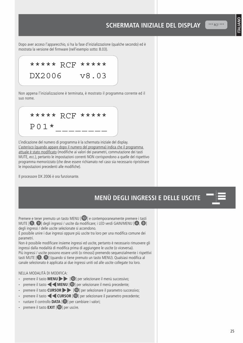
SCHERMATA INIZIALE DEL DISPLAY
Dopo aver acceso l’apparecchio, si ha la fase d’inizializzazione (qualche secondo) ed è mostrata la versione del firmware (nell’esempio sotto: 8.03).
Non appena l’inizializzazione è terminata, è mostrato il programma corrente ed il suo nome.
L’indicazione del numero di programma è la schermata iniziale del display.L’asterisco (quando appare dopo il numero del programma) indica che il programma attuale è stato modificato (modifiche ai valori dei parametri, commutazione dei tasti MUTE, ecc.), pertanto le impostazioni correnti NON corrispondono a quelle del rispettivo programma memorizzato (che deve essere richiamato nel caso sia necessario ripristinare le impostazioni precedenti alle modifiche).
Il processore DX 2006 è ora funzionante.
*** RCF ***
***** RCF *****DX2006 v8.03
***** RCF *****P01*________
Premere e tener premuto un tasto MENU [P] e contemporaneamente premere i tasti MUTE [5, 9] degli ingressi / uscite da modificare; i LED verdi GAIN/MENU [4, 8] degli ingressi / delle uscite selezionate si accendono. È possibile unire i due ingressi oppure più uscite tra loro per una modifica comune dei parametri.Non è possibile modificare insieme ingressi ed uscite, pertanto è necessario rimuovere gli ingressi dalla modalità di modifica prima di aggiungere le uscite (o viceversa).Più ingressi / uscite possono essere uniti (o rimossi) premendo sequenzialmente i rispettivi tasti MUTE [5, 9] (quando si tiene premuto un tasto MENU). Qualsiasi modifica al canale selezionato è applicata ai due ingressi uniti od alle uscite collegate tra loro.
NELLA MODALITÀ DI MODIFICA:premere il tasto MENU [P] per selezionare il menù successivo;premere il tasto MENU [P] per selezionare il menù precedente;premere il tasto CURSOR [P] per selezionare il parametro successivo;premere il tasto CURSOR [P] per selezionare il parametro precedente;ruotare il controllo DATA [{] per cambiare i valori;premere il tasto EXIT [P] per uscire.
------
MENÙ DEGLI INGRESSI E DELLE USCITE

2�
ITA
LIA
NO
I MENÙ DISPONIBILI SONO: SIGNAL (segnale audio)EQ (equalizzatore a 8 bande, da EQ1 a EQ8) XOVER (crossover; disponibile solo per le uscite)LIMIT (limitatore; disponibile solo per le uscite)SOURCE (miscelazione degli ingressi; disponibile solo per le uscite)NAME (nome)
INDICAZIONI SUL DISPLAY:
C : canale selezionato per le modificheI1 : ingresso 1, I2 : ingresso 2O1 : uscita 1, O2 : uscita 2, O3 : uscita 3, O4 : uscita 4
sE I 2 INgrEssI o pIù UscITE soNo collEgaTI Tra loro, qUalsIasI ModIfIca è coMUNE a TUTTI I caNalI sElEzIoNaTI (NoNosTaNTE Il dIsplay INdIchI solo UN caNalE NEl sUo aNgolo IN alTo a sINIsTra).
M : menù selezionato
P : parametro selezionato ed il suo valore
------
••
I1:_____ SignalLEVEL:0.00dB
C M
P
INDICAZIONI SUL DISPLAY
I1:_____ SignalLEVEL:0.00dB
LEVEL(livello)Livello del segnale (da – 40 dB a + 15 dB con passi da 0,25 dB).
POL (polarità)Polarità (fase) del segnale, che può essere normale (+) od invertita (–). La polarità normale (+) è quella consigliata e preimpostata.
l’INvErsIoNE dI fasE poTrEbbE EssErE UTIlE pEr coMpENsarE or MINIMIzzarE possIbIlI (Ed INdEsIdEraTE) INTErfErENzE acUsTIchE dIsTrUTTIvE dovUTE, pEr EsEMpIo, a parTIcolarI posIzIoNI dEI dIffUsorI acUsTIcI.
DELAY (ritardo)Ritardo del segnale (tempo: 0 ÷ 40 ms, con passi da c. 10 μS). Premere e tenere premuto il tasto ENTER per aumentare / diminuire il tempo con passi da ca. 1 secondo). Il ritardo può essere indicato in millisecondi (ms) o negli equivalenti “piedi” (“feet”, abb. “ft”) o in metri (m); questa impostazione è descritta nella sezione del manuale “Menù di sistema”.
I1:_____ SignalPOL:+
I1:_____ SignalDELAY:000.000ms
MENÙ SIGNAL (SEGNALE)MENÙ SIGNAL (SEGNALE)

2�
ITA
LIA
NO
I1:______ EQ1EQ#:1
EQ#Selezione della banda da modificare tra le 8 disponibili (EQ1 ÷ EQ8).
BYPASSQuesto parametro, se impostato su ON, disattiva l’equalizzatore nella banda selezionata.
TYPE (tipo)È possibile scegliere tra 5 tipi di equalizzatore:
parametrico (PEQ)filtro “low-shelf” (LO-SHF)filtro “hi-shelf” (HI-SHF)filtro passa-tutto di primo ordine (AP-1)filtro passa-tutto di secondo ordine (AP-2)
EQUALIZZATORE PARAMETRICO (PEQ): permette di impostare il livello L nella frequenza centrale selezionata Fc e di specificare l’ampiezza di banda BW su cui intervenire.
-----
I1:______ EQ1BYPASS:Off
I1:______ EQ1TYPE:PEQ
Il filtro “Low-shelf” aumenta o diminuisce il livello (secondo un valore specifico) di tutte le frequenze sotto quella centrale.
Il filtro “Hi-shelf” aumenta o diminuisce il livello (secondo un valore specifico) di tutte le frequenze sopra quella centrale.
I filtri “All-pass” lasciano passare equamente tutte le frequenze, ma cambiano la fase.
FREQImpostazione della frequenza centrale: da 20 Hz a 30 kHz con passi da 1 Hz o 1/36 d’ottava (la scelta si effettua nel “menù di sistema”; vedere la relativa sezione del manuale).
BW (solo PEQ e filtri LO-SHF, HI-SHF, AP-2)Impostazione della larghezza di banda.Il campo è compreso tra 0,02 e 3.61 ottave (con passi da 0,01).L’equivalente “fattore di merito” (Q) è automaticamente mostrato a fianco del valore d’ottava.
DEG (solo filtro AP-1)Se è selezionato il filtro passa-tutto di primo ordine (AP-1), questo parametro permette di impostare l’angolo di sfasamento alla frequenza centrale. La fase cambia gradualmente da 180 gradi fino al valore specificato della frequenza centrale.
LEVEL (solo PEQ e filtri LO-SHF, HI-SHF)Impostazione del livello dell’equalizzatore, tra –30,00 dB a +15,00 dB, con passi da 0,25 dB.
PEQ
I1:______ EQ1FREQ:1000Hz
I1:______ EQ1BW:0.33 Q=4.36
I1:______ EQ1DEG:15.5 deg
I1:______ EQ1LEVEL:0.00dB
MENÙ EQ (EQUALIZZAZIONE)MENÙ EQ (EQUALIZZAZIONE)

2�
ITA
LIA
NO
O1:______ XOverTYPL:Off
I “crossovEr” soNo NEcEssarI pEr sUddIvIdErE UN sEgNalE aUdIo IN baNdE dI frEqUENzE sEparaTE (IN Modo da oTTENErE sIsTEMI MUlTIvIa), chE possoNo EssErE rIprodoTTE da dIvErsI TIpI dI alToparlaNTI spEcIfIcI (Es. “woofEr” pEr lE bassE frEqUENzE, “MIdraNgE” pEr lE MEdIE, “TwEETEr” pEr lE alTE).
TYPL (tipo filtro per la frequenza inferiore della banda)Permette di scegliere il tipo di filtro passa-alto tra Butterworth, Linkwitz-Riley o Bessel.L’impostazione OFF disabilità il filtro passa-alto.
FRQL (frequenza inferiore della banda)
Impostazione della frequenza di taglio del filtro passa-alto, tra 20 Hz e 30 kHz, con passi da 1 Hz o 1/36 d’ottava (la scelta si effettua nel “menù di sistema”; vedere la relativa sezione del manuale).
SLPL (pendenza filtro per la frequenza inferiore della banda)Impostazione della pendenza del filtro passa-alto.Le pendenze disponibili sono:
da 6 dB a 48 dB, con passi da 6 dB, per i filtri Butterworth e Bessel;da 12 dB a 48 dB, con passi da 12 dB, per il filtro Linkwitz-Riley.
TYPH (tipo filtro per la frequenza superiore della banda)Permette di scegliere il tipo di filtro passa-basso tra Butterworth, Linkwitz-Riley o Bessel.L’impostazione OFF disabilità il filtro passa-basso.
FRQH (frequenza superiore della banda)
Impostazione della frequenza di taglio del filtro passa-basso, tra 20 Hz e 30 kHz, con passi da 1 Hz o 1/36 d’ottava (la scelta si effettua nel “menù di sistema”; vedere la relativa sezione del manuale).
SLPH (pendenza filtro per la frequenza superiore della banda)Impostazione della pendenza del filtro passa-basso.Le pendenze disponibili sono:
da 6 dB a 48 dB, con passi da 6 dB, per i filtri Butterworth e Bessel;da 12 dB a 48 dB, con passi da 12 dB, per il filtro Linkwitz-Riley.
l’INsErzIoNE dI ENTraMbI I fIlTrI (passa-alTo E passa-basso) pErMETTE dI rEalIzzarE UN fIlTro passa-baNda.
--
--
O1:______ XOverFRQL:1000Hz
O1:______ XOverSLPL:24dB
O1:______ XOverTYPH:Off
O1:______ XOverFRQH:1000Hz
O1:______ XOverSLPH:24dB
MENÙ XOVERMENÙ XOVER (CROSSOVER, DISPONIBILE SOLO PER LE USCITE)
FRQL
L
F
FRQH
L
F
FRQL
L
FFRQH

2�
ITA
LIA
NO
O1:______ LimitTHRESH:+20.0dB
Il lIMITaTorE (“lIMITEr”) lascIa INalTEraTo UN sEgNalE avENTE UN lIvEllo INfErIorE alla soglIa prEfIssaTa Ed INvEcE aTTENUa UN sEgNalE coN lIvEllo sUpErIorE.
THRESH (“Threshold”: soglia)Impostazione della soglia tra i livelli –20 e +20 dBu (con passi da 0,5 dBu).
ATTACK (attacco)Impostazione del tempo di inserimento del limitatore tra 0,3 e 1 ms (con passi da 0,1 ms) oppure tra 1 e 100 ms (con passi da 1 ms).
RELEASE (rilascio)Impostazione del tempo di rilascio del limitatore, che può essere 2X (2 volte), 4X, 8X, 16X o 32X il tempo di inserimento “Attack”.
O1:______ LimitATTACK:10ms
O1:______ LimitRELEASE:8XAtck
IN1Impostazione del livello dell’ingresso 1 verso l’uscita selezionata. Si utilizza per miscelare l’ingresso 1 (impostando il livello da –40 a 0 dB) o per disabilitarlo (OFF).
IN2Impostazione del livello dell’ingresso 2 verso l’uscita selezionata. Si utilizza per miscelare l’ingresso 2 (impostando il livello da –40 a 0 dB) o per disabilitarlo (OFF).
sE ENTraMbI glI INgrEssI soNo abIlITaTI, sI ha la loro MIscElazIoNE vErso l’UscITa sElEzIoNaTa.
O1:______ SourceIN1:Off
O1:______ SourceIN2:-14.00
NAME (nome)Ad ogni ingresso / uscita si può assegnare un nome composto da 6 caratteri.Premere il tasto CURSOR [P] per selezionare il carattere successivo.Premere il tasto CURSOR [P] per ritornare al carattere precedente.Ruotare il controllo DATA [{] per cambiare i caratteri.
I1:______ NameNAME:______
MENÙ LIMITMENÙ LIMIT (LIMITATORE, DISPONIBILE SOLO PER LE USCITE)
MENÙ SOURCE MENÙ SOURCE (MISCELAZIONE DEGLI INGRESSI, MENÙ DISPONIBILE SOLO PER LE USCITE)
MENÙ NAME (NOME)MENÙ NAME (NOME)

30
ITA
LIA
NO
MENÙ DI SISTEMA
I menù di sistema consentono all’utente di controllare e cambiare i parametri relativi al funzionamento dell’unità e delle sue funzioni generiche. Per accedere ai menù, occorre premere il tasto ENTER [P] quando il display mostra la pagina iniziale “nr. programma” (e quindi non è in corso alcuna modifica dei parametri degli ingressi o delle uscite).All’interno dei menù di sistema, è necessario premere due volte il tasto ENTER [P] per confermare e salvare le nuove impostazioni.
NEI MENÙ DI SISTEMA:premere il tasto MENU [P] per selezionare il menù successivo;premere il tasto MENU [P] per selezionare il menù precedente;premere il tasto CURSOR [P] per selezionare il parametro successivo;premere il tasto CURSOR [P] per selezionare il parametro precedente;ruotare il controllo DATA [{] per cambiare i valori;premere il tasto ENTER [P] per procedere / confermare;premere il tasto EXIT per uscire.
I MENÙ DISPONIBILI SONO: PRESET RECALL (“Recall” sul display): richiamo dei programmiPRESET STORE (“Store” sul display): memorizzazione dei programmi INPUT / OUPUT COPY (“Copy” sul display): copia degli ingressi / delle uscite GENERAL SETTINGS (“Generl” sul display): impostazioni genericheCOMMUNICATION SETTINGS (“Comm” sul display): impostazioni porta serialeSECURITY (“Secure” sul display): inserimento passwordFACTORY SETTINGS (“Reset” sul display): ripristino impostazioni di fabbricaINTERNAL SYSTEM OPTIMIZER (“ISO” sul display): impostazioni del “noise gate” INFO (informazioni)
-------
---------
MENÙ PRESET RECALL (richiamo dei programmi)
P:nQuesto parametro permette di selezionare quale programma (n) sarà richiamato dalla memoria interna.Il nome del programma è mostrato a fianco del numero.
MENÙ PRESET STORE (memorizzazione dei programmi)
La memoria interna del processore DX 2006 può mantenere 30 programmi differenti.
Un programma può essere memorizzato tramite questo menù. Le impostazioni precedenti dello stesso programma saranno sostituite da quelle nuove. Non appena il programma è memorizzato, potrà sempre essere richiamato (“recall”) successivamente, persino dopo aver spento l’apparecchio.
P:nQuesto parametro permette di selezionare quale programma (n) sarà memorizzato nella memoria interna.
NAM:Si può assegnare un nome di max. 12 caratteri a ciascun programma. Premere il tasto CURSOR [P] per selezionare il carattere successivo.Premete il tasto CURSOR [P] per ritornare al carattere precedente.Ruotare il controllo DATA [{] per cambiare i caratteri.
MENÙ PRESET RECALL
MENÙ PRESET STORE
SYSTEM RecallP:1 _________
SYSTEM StoreP:1
SYSTEM StoreNAM:_________

31
ITA
LIA
NO
MENÙ INPUT / OUTPUT COPY (copia degli ingressi / delle uscite)
È POSSIBILE COPIARE I DATI RELATIVI AGLI INGRESSI ED ALLE USCITE:se si effettua la copia da un ingresso all’altro, sono copiati tutti i valori dei parametri;se si effettua la copia da un’uscita all’altra, sono copiati tutti i valori dei parametri;se si effettua la copia un ingresso verso un’uscita (o viceversa), sono copiati solo i valori dei parametri “Level” (livello), “Polarity” (polarità), “Delay” (ritardo), “EQ” (equalizzatori) e “Name” (nome).
SOURCE (sorgente, origine)Ingresso / uscita da cui sono prelevati i dati.
TARGET (destinazione)Ingresso / uscita in cui sono copiati i dati.
MENÙ GENERAL SETTINGS (impostazioni generiche)
FREQ MODE (risoluzione della frequenza)Scelta della risoluzione della frequenza nelle impostazioni degli equalizzatori e dei crossover: può essere in trentaseiesimi d’ottava oppure 1 Hz (tutte le frequenze, “All”).
DELAY UNIT (unità di misura della linea di ritardo)Il ritardo può essere indicato in millisecondi (ms) o negli equivalenti “piedi” (ft) oppure metri (m).
MENÙ COMMUNICATION SETTINGS (impostazioni porta seriale)
NoTa: l’apparEcchIo dEvE EssErE spENTo E poI rIaccEso prIMa chE lE NUovE IMposTazIoNI abbIaNo EffETTo.
DEVICE ID (numero identificativo) Impostazione del numero identificativo ID (da 1 a 16) dell’unità.Il numero identificativo serve solo quando sono presenti più DX 2006 in una rete; normalmente è impostato a 1.
BAUD RATE (velocità di trasmissione / ricezione)Impostazione della velocità della comunicazione seriale.Il software per PC ‘XConsole’ necessita di un “baud rate” 115200, pertanto lasciare inalterato questo parametro.
MENÙ SECURITY (inserimento password)
PASSWORDUn nuovo DX 2006 non richiede l’inserimento della password.L’unità può essere protetta contro eventuali modifiche ai parametri non autorizzate tramite una password di 4 caratteri, che può essere memorizzata solo quando si utilizza il software per PC ‘Xconsole’.Dopo aver inserito la password corretta, i parametri saranno modificabili; dopo aver inserito una seconda volta la password (o spento l’apparecchio), i parametri saranno di nuovo protetti.Premere il tasto [P] per selezionare il carattere successivo.Premete il tasto CURSOR [P] per ritornare al carattere precedente.Ruotare il controllo [{] per cambiare i caratteri.
---
MENÙ INPUT / OUTPUT COPY
GENERAL SETTINGS MENU
MENÙ COMMUNICATION SETTINGS
MENÙ SECURITY
SYSTEM CopySOURCE:In1
SYSTEM CopyTARGET:In2
SYSTEM GenerlFREQ MODE:All
SYSTEM GenerlDELAY UNIT:ms
SYSTEM CommDEVICE ID:1
SYSTEM CommBAUD RATE:115200
SYSTEM SecurePASSWORD:____
32
ITA
LIA
NO
MENÙ FACTORY SETTINGS (ripristino impostazioni di fabbrica)
RESET CURRENT (ripristino dei parametri)Se necessario, si possono ripristinare i valori preimpostati di fabbrica dei parametri: ruotare il controllo DATA [11] per selezionare YES, poi premere ENTER [10] due volte (la seconda per confermare).
NoTa: I prograMMI gIà MEMorIzzaTI E lE IMposTazIoNI dI sIsTEMa NoN soNo ModIfIcaTI.
aTTENzIoNE: qUEsTa fUNzIoNE caNcElla TUTTE lE ModIfIchE EvENTUalMENTE apporTaTE aI paraMETrI!
MENÙ INTERNAL SYSTEM OPTIMIZER (“noise gate”)
L’apparecchio dispone della funzione “noise gate”, ovvero un controllo automatico del volume che attenua il rumore di fondo (il fruscio) quando nessun segnale è presente agli ingressi audio.
THRESHOLD (soglia di intervento, sensibilità)La soglia di intervento può essere regolata (da 80 a 120).
BYPASS (disattivazione)Se l’effetto del “noise gate” risulta essere fastidioso (solitamente con segnali di livello basso), la funzione può essere disattivata impostando il parametro BYPASS su ON.
MENÙ INFO (informazioni)
NAM (nome)È mostrato il nome dell’unità.
FIRMWAREÈ indicata l’attuale versione del firmware.
CODE (codice controllo inserimento password)Questo codice è 11110000 se nessuna password di sicurezza è stata impostata.Se il codice è diverso da 11110000, la password di sicurezza è stata impostata ed i parametri non possono essere modificati dall’utente senza aver prima inserito la password corretta.
MENÙ FACTORY SETTINGS
MENÙ INTERNAL SYSTEM OPTIMIZER
MENÙ INFO
SYSTEM InfoNAM:_________
SYSTEM InfoFIRMWARE:v8.00
SYSTEM InfoCODE:11110000
SYSTEM ResetCURRENT:Yes
SYSTEM ISOTHRESHOLD:102
SYSTEM ISOBYPASS:On
33
ITA
LIA
NO
MENÙ PARAMETRO VALORE MIN. VALORE MAX. PASSI UNITÀ DI MISURA
Segnale
Livello – 40 + 15 0,25 dB
Polarità + / –
Ritardo
0 40 0,010 / 0,011 mS
0 45,538 0,011 / 0,012 ft
0 13,876 0,003 / 0,004 m
Equalizzatore
EQ (numero) 1 8 1
Bypass Off / On
Tipo PEQ / LO-SHF / HI-SHF / AP-1 / AP-2
Frequenza 20 30 000 1 Hz / 1/36ott Hz / ottave
Larghezza di banda 0,02 3,61 0,01 ottave
Fase (AP-1) 0 179,5 0,5 gradi
Livello – 30 + 15 0,25 dB
Crossover(passa-alto,
passa-basso)
Tipo Off / Butterworth / Linkwitz-Riley / Bessel
Frequenza di taglio 20 30 000 1 Hz / 1/36ott Hz / ottave
Slope 6 /(12 LR) 48 6 / (12 LR) dB
Limitatore
Livello di soglia – 20 + 20 0,5 dBu
Tempo di attacco 0,3 100 0,1 / 1 ms
Tempo di rilascio 2x / 4x / 8x / 16x / 32x il tempo di attacco
SorgenteLivello ingresso 1 Off / – 40 0 0,25 dB
Livello ingresso 2 Off / – 40 0 0,25 dB
Nome Nome 6 caratteri
TABELLA PARAMETRI DI CANALE
SOFTWARE PER PCIl DX 2006 ha a corredo un software, “Xconsole”, per la configurazione grafica dell’unità tramite un computer (PC).I programmi possono essere richiamati e memorizzati da e verso l’hard disk del PC.Il processore DX 2006 può essere collegato al PC tramite interfaccia RS232 oppure USB.La connessione USB potrebbe richiedere l’installazione di driver addizionali.

3�
ITA
LIA
NO
DATI TECNICI
INGRESSI ED USCITEImpedenza ingressi:
Impedenza uscite:Livello massimo:
Tipo:
PRESTAZIONI AUDIORisposta in frequenza:
Dinamica: Rapporto reiezione di modo comune:
Diafonia: Distorsione:
AUDIO DIGITALEProcessore:
Frequenza di campionamento:Convertitori:
Latenza:
CONTROLLI PANNELLO FRONTALEDisplay:
Indicatori livello segnale:Tasti:
Modifica dati:
CONNETTORIIngressi analogici:Uscite analogiche:
RS-232: USB:
Alimentazione:
PARAMETRI DI CONTROLLO AUDIOGuadagno:
Polarità: Ritardo:
Unità di misura della linea di ritardo:
EQUALIZZATORI (8 PER INGRESSO / USCITA)Tipo:
Guadagno:Larghezza di banda:
CROSSOVER (2 PER USCITA)Tipo:
Pendenza:
LIMITATORI (1 PER OGNI USCITA)Soglia di intervento:
Tempo di attacco:Tempo di rilascio:
DATI GENERICINumero di programmi:
Scelta frequenze: Tensione di funzionamento:
Dimensioni (l, h, p):Peso netto:
>10 kΩ50 Ω+20 dBuBilanciati elettronicamente
± 0,1 dB (20 ÷ 30 kHz)115 dB tip. (non pesato)> 60dB (50 ÷ 10 kHz)< – 100 dB0,002% (1 kHz a +4 dBu)
40 bit96 kHz24-bit1,5 ms
LCD retroilluminato, 2 linee x 16 caratteri5 LED per canale “Mute” (scelta canali modificabili), controlli dei menùcontrollo rotante (“encoder”) DATA
XLR tripolare femminaXLR tripolare maschioconnettore DE-9Tipo BPresa standard IEC con fusibile
– 40 ÷ +15 dB in passi da 0,25 dB+ / – fino a 40 ms per ingresso / uscitams, ft, m
Parametrico, Lo-shelf, Hi-shelf, AP-1, AP-2–15 ÷ +15 dB in passi da 0,25 dBda 0,02 a 3,61 ottave
Butterworth, Linkwitz-Riley, Besselda 6 / 12 a 48 dB / ott
–20 ÷ +20 dBu0,3 ÷ 100 ms2-4-8-16-32x il tempo di attacco
30risoluzione di 1 Hz oppure trentaseiesimi d’ottava 90 ÷ 240 V c.a. (50-60 Hz)483 x 44 x 229 mm (1 unità rack 19”)4,5 kg


www.rcfaudio.com
103
07 2
65 R
evA
RCF SpA: Via Raffaello, 13 - 42124 Reggio Emilia > Italytel. +39 0522 274411 - fax +39 0522 274484 - e-mail: [email protected]