Embed Size (px)
Citation preview
L ow-Budget Hydro-formingWe are often looking for methods for cre-
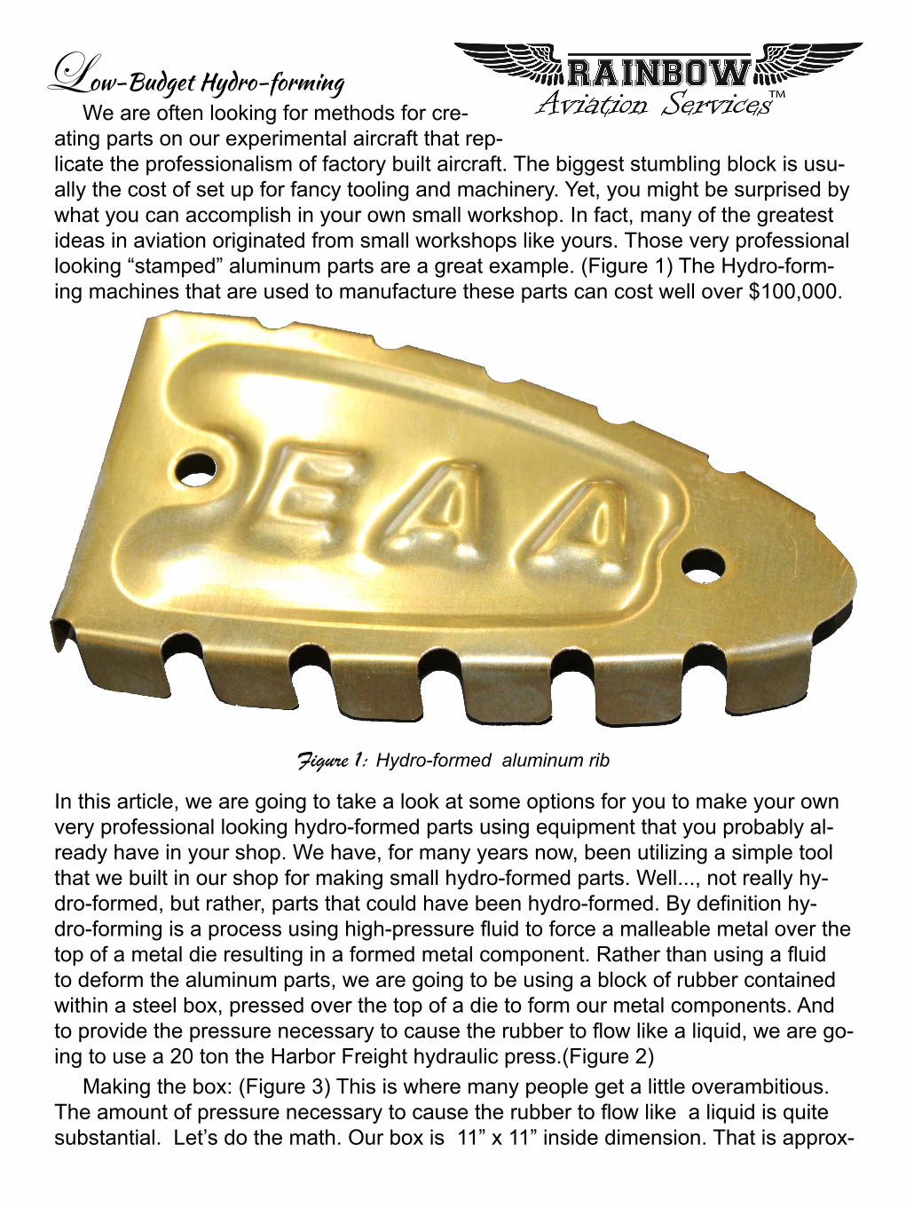
ating parts on our experimental aircraft that rep-licate the professionalism of factory built aircraft. The biggest stumbling block is usu-ally the cost of set up for fancy tooling and machinery. Yet, you might be surprised by what you can accomplish in your own small workshop. In fact, many of the greatest ideas in aviation originated from small workshops like yours. Those very professional looking “stamped” aluminum parts are a great example. (Figure 1) The Hydro-form-ing machines that are used to manufacture these parts can cost well over $100,000.
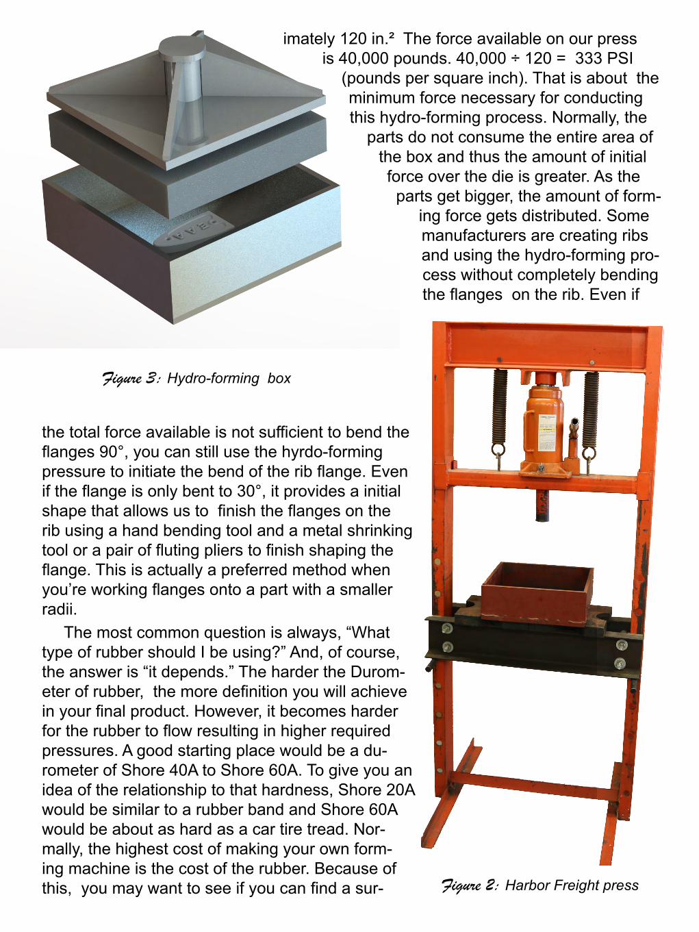
In this article, we are going to take a look at some options for you to make your own very professional looking hydro-formed parts using equipment that you probably al-ready have in your shop. We have, for many years now, been utilizing a simple tool that we built in our shop for making small hydro-formed parts. Well..., not really hy-dro-formed, but rather, parts that could have been hydro-formed. By definition hy-dro-forming is a process using high-pressure fluid to force a malleable metal over the top of a metal die resulting in a formed metal component. Rather than using a fluid to deform the aluminum parts, we are going to be using a block of rubber contained within a steel box, pressed over the top of a die to form our metal components. And to provide the pressure necessary to cause the rubber to flow like a liquid, we are go-ing to use a 20 ton the Harbor Freight hydraulic press.(Figure 2)
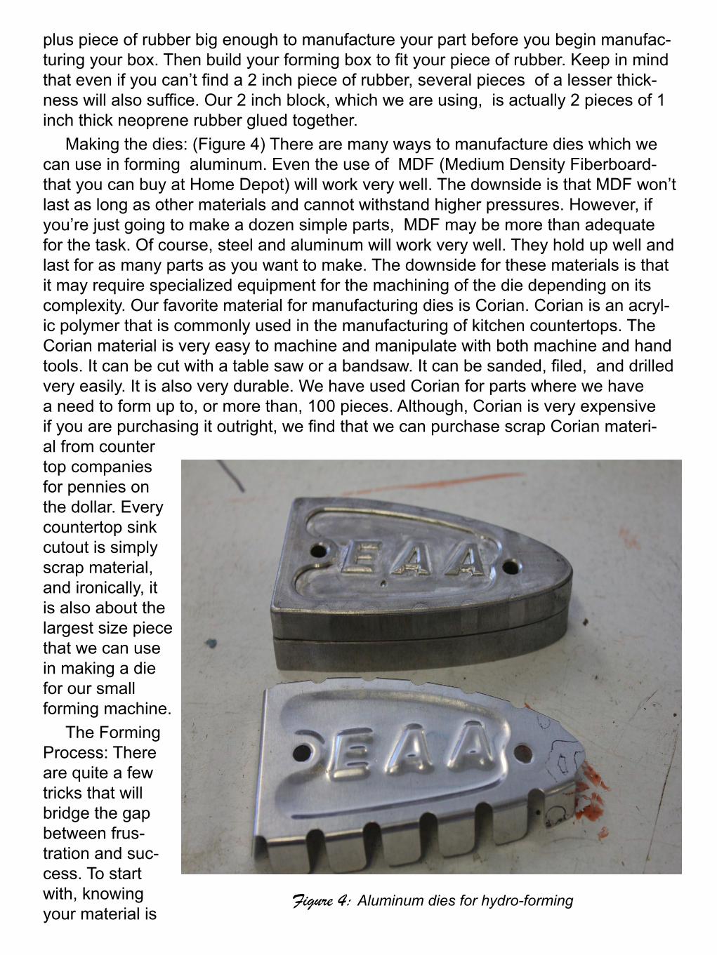
Making the box: (Figure 3) This is where many people get a little overambitious. The amount of pressure necessary to cause the rubber to flow like a liquid is quite substantial. Let’s do the math. Our box is 11” x 11” inside dimension. That is approx-
Figure 1: Hydro-formed aluminum rib
imately 120 in.² The force available on our press is 40,000 pounds. 40,000 ÷ 120 = 333 PSI
(pounds per square inch). That is about the minimum force necessary for conducting this hydro-forming process. Normally, the
parts do not consume the entire area of the box and thus the amount of initial force over the die is greater. As the parts get bigger, the amount of form-
ing force gets distributed. Some manufacturers are creating ribs and using the hydro-forming pro-cess without completely bending the flanges on the rib. Even if
the total force available is not sufficient to bend the flanges 90°, you can still use the hyrdo-forming pressure to initiate the bend of the rib flange. Even if the flange is only bent to 30°, it provides a initial shape that allows us to finish the flanges on the rib using a hand bending tool and a metal shrinking tool or a pair of fluting pliers to finish shaping the flange. This is actually a preferred method when you’re working flanges onto a part with a smaller radii.
The most common question is always, “What type of rubber should I be using?” And, of course, the answer is “it depends.” The harder the Durom-eter of rubber, the more definition you will achieve in your final product. However, it becomes harder for the rubber to flow resulting in higher required pressures. A good starting place would be a du-rometer of Shore 40A to Shore 60A. To give you an idea of the relationship to that hardness, Shore 20A would be similar to a rubber band and Shore 60A would be about as hard as a car tire tread. Nor-mally, the highest cost of making your own form-ing machine is the cost of the rubber. Because of this, you may want to see if you can find a sur- Figure 2: Harbor Freight press
Figure 3: Hydro-forming box
plus piece of rubber big enough to manufacture your part before you begin manufac-turing your box. Then build your forming box to fit your piece of rubber. Keep in mind that even if you can’t find a 2 inch piece of rubber, several pieces of a lesser thick-ness will also suffice. Our 2 inch block, which we are using, is actually 2 pieces of 1 inch thick neoprene rubber glued together.
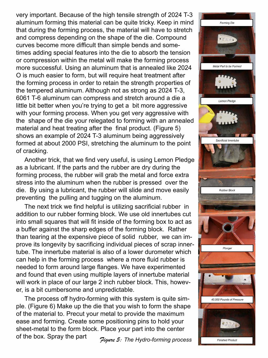
Making the dies: (Figure 4) There are many ways to manufacture dies which we can use in forming aluminum. Even the use of MDF (Medium Density Fiberboard- that you can buy at Home Depot) will work very well. The downside is that MDF won’t last as long as other materials and cannot withstand higher pressures. However, if you’re just going to make a dozen simple parts, MDF may be more than adequate for the task. Of course, steel and aluminum will work very well. They hold up well and last for as many parts as you want to make. The downside for these materials is that it may require specialized equipment for the machining of the die depending on its complexity. Our favorite material for manufacturing dies is Corian. Corian is an acryl-ic polymer that is commonly used in the manufacturing of kitchen countertops. The Corian material is very easy to machine and manipulate with both machine and hand tools. It can be cut with a table saw or a bandsaw. It can be sanded, filed, and drilled very easily. It is also very durable. We have used Corian for parts where we have a need to form up to, or more than, 100 pieces. Although, Corian is very expensive if you are purchasing it outright, we find that we can purchase scrap Corian materi-al from counter top companies for pennies on the dollar. Every countertop sink cutout is simply scrap material, and ironically, it is also about the largest size piece that we can use in making a die for our small forming machine.
The Forming Process: There are quite a few tricks that will bridge the gap between frus-tration and suc-cess. To start with, knowing your material is
Figure 4: Aluminum dies for hydro-forming
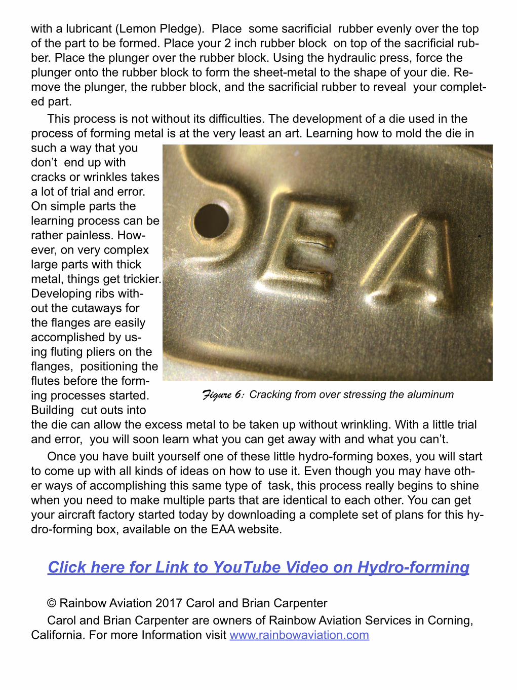
very important. Because of the high tensile strength of 2024 T-3 aluminum forming this material can be quite tricky. Keep in mind that during the forming process, the material will have to stretch and compress depending on the shape of the die. Compound curves become more difficult than simple bends and some-times adding special features into the die to absorb the tension or compression within the metal will make the forming process more successful. Using an aluminum that is annealed like 2024 O is much easier to form, but will require heat treatment after the forming process in order to retain the strength properties of the tempered aluminum. Although not as strong as 2024 T-3, 6061 T-6 aluminum can compress and stretch around a die a little bit better when you’re trying to get a bit more aggressive with your forming process. When you get very aggressive with the shape of the die your relegated to forming with an annealed material and heat treating after the final product. (Figure 5) shows an example of 2024 T-3 aluminum being aggressively formed at about 2000 PSI, stretching the aluminum to the point of cracking.
Another trick, that we find very useful, is using Lemon Pledge as a lubricant. If the parts and the rubber are dry during the forming process, the rubber will grab the metal and force extra stress into the aluminum when the rubber is pressed over the die. By using a lubricant, the rubber will slide and move easily preventing the pulling and tugging on the aluminum.
The next trick we find helpful is utilizing sacrificial rubber in addition to our rubber forming block. We use old innertubes cut into small squares that will fit inside of the forming box to act as a buffer against the sharp edges of the forming block. Rather than tearing at the expensive piece of solid rubber, we can im-prove its longevity by sacrificing individual pieces of scrap inner-tube. The innertube material is also of a lower durometer which can help in the forming process where a more fluid rubber is needed to form around large flanges. We have experimented and found that even using multiple layers of innertube material will work in place of our large 2 inch rubber block. This, howev-er, is a bit cumbersome and unpredictable.
The process off hydro-forming with this system is quite sim-ple. (Figure 6) Make up the die that you wish to form the shape of the material to. Precut your metal to provide the maximum ease and forming. Create some positioning pins to hold your sheet-metal to the form block. Place your part into the center of the box. Spray the part Figure 5: The Hydro-forming process
with a lubricant (Lemon Pledge). Place some sacrificial rubber evenly over the top of the part to be formed. Place your 2 inch rubber block on top of the sacrificial rub-ber. Place the plunger over the rubber block. Using the hydraulic press, force the plunger onto the rubber block to form the sheet-metal to the shape of your die. Re-move the plunger, the rubber block, and the sacrificial rubber to reveal your complet-ed part.
This process is not without its difficulties. The development of a die used in the process of forming metal is at the very least an art. Learning how to mold the die in such a way that you don’t end up with cracks or wrinkles takes a lot of trial and error. On simple parts the learning process can be rather painless. How-ever, on very complex large parts with thick metal, things get trickier. Developing ribs with-out the cutaways for the flanges are easily accomplished by us-ing fluting pliers on the flanges, positioning the flutes before the form-ing processes started. Building cut outs into the die can allow the excess metal to be taken up without wrinkling. With a little trial and error, you will soon learn what you can get away with and what you can’t.
Once you have built yourself one of these little hydro-forming boxes, you will start to come up with all kinds of ideas on how to use it. Even though you may have oth-er ways of accomplishing this same type of task, this process really begins to shine when you need to make multiple parts that are identical to each other. You can get your aircraft factory started today by downloading a complete set of plans for this hy-dro-forming box, available on the EAA website.
Click here for Link to YouTube Video on Hydro-forming
© Rainbow Aviation 2017 Carol and Brian CarpenterCarol and Brian Carpenter are owners of Rainbow Aviation Services in Corning,
California. For more Information visit www.rainbowaviation.com
Figure 6: Cracking from over stressing the aluminum