Embed Size (px)
Citation preview
International Research Journal of Engineering and Technology (IRJET) e-ISSN: 2395 -0056
Volume: 02 Issue: 05 | Aug-2015 www.irjet.net p-ISSN: 2395-0072
© 2015, IRJET ISO 9001:2008 Certified Journal Page 902
Numerical and Experimental Study of the hydroforming process for
forming the spherical parts
Mahmoud Samadi3، Kaveh Rahmani 2 ،AliReza Rahmani1
1 MS in Manufacturing Engineering, Islamic Azad University, Science and Research Branch Kermanshah,Iran 2 Undergraduate Manufacturing Engineering, Islamic Azad University Branch of Takestan,Iran
3 MS of Applied Engineering, Islamic Azad University Branch of Takestan,Iran
---------------------------------------------------------------------***---------------------------------------------------------------------Abstract - One of the processes ofsheet metal
formingdefined as Hydromechanical deep drawing. In
this paper, changing the minimum thickness of the
sheetin the hydro-mechanical deep drawing process is
reviewedexperimentally and numerically.For this
purpose, the hemispherical parts in the laboratory
process are used.Numerical ABAQUS softwareis used in
order to solve the numerical of the hydro mechanical
deep drawing process of hemispherical
parts.Coefficients of friction between the punch, sheet
and clamp and fluid pressure on the curve of elasticity
and thickness change is analysed completely. The sheet
shrinkage in the flange area is also examined. In order
to confirm the results of finite element simulation a
studyconducted with laboratory equipmentand the
results were compared.It was noted that no wrinkling
and thinning parts were made in the flange.
Key Words: Hydroforming forming, deep drawing,
parts hemispherical, numerical ABAQUS
1. INTRODUCTION
Sheet metal formingand causing plastic deformation of the
sheet is to produce adesired piece of geometry. The
technology in the production of components used in
various industries is including the automotive and
aerospace industries. Various processes occurs such as
deep drawing, expansion, bending, machining for forming
plates, which they were used to produce pieces, depending
on factors such as work piece geometry, material of the
sheetand volume of the deformation and so on. There are
limitations on conversion processes andsheet production
that necessitatea suitableproduction of the piece. Because
the processes havedrawing nature, instability in stretching
and tearing is animportant limiting factor in conversion
processes.
Folding sheets caused by compressive tensions in parts of
the piece, spring back and thickness non-uniformity
distribution are among the other defects that are caused in
these processes.
Basically, fewer restrictions on the sheetwork process,
costs reduction and increaseof theflexibility are among the
things that have always been favoured in designing and
carrying out these processes. This problem is enhanced by
increasing use of lightweight high-strength alloys that
make the conversion process facedwith problems and
further restrictions and the need to produce various parts
with complex shapes is enhanced.
Baratamarkvs [1] has studied the experimental and
theoretical analysis of asymmetric forms with ABAQUS
software and the effect of friction coefficient. Meryra and
FEROON [2] investigated tearing in the formation of
spherical parts using numerical and experimental analysis.
Abdullah Shaaban [3] has been examined numerically
strain rate effect on hydroforming parts of the spherical
shape. Yoshida and Katayama [4] studied formation of
spherical parts with high strength sheet numerically.
Chrome and Etheridge [5] investigatedspherical copper
parts by using the finite element method with changing
the shape in several stages, with thedistribution of loading
pressure.
Dailami and colleagues [6], by numerical simulation of
hydromechanical deep drawing process and experiments,
studied the effect of factors such as pre-bulge pressure,the
bulge height and thickness distribution over the chamber
pressure in the cylindrical parts.
The most important parameters in the process of thinning and thickening in hydromechanical deep drawing for aconstant draw ratio including chamber pressure, pre-bulge pressure, pre-bulge height and the distance between the plate and the clamp. The purpose of this paper is to analyze hydromechanical deep drawing process
International Research Journal of Engineering and Technology (IRJET) e-ISSN: 2395 -0056
Volume: 02 Issue: 05 | Aug-2015 www.irjet.net p-ISSN: 2395-0072
© 2015, IRJET ISO 9001:2008 Certified Journal Page 903
numerically and experimentally, which in particular, the spherical parts have been examined. The impact of changes in chamber pressure, pre-bulge pressureand height of the tablet and punch on thedistribution of the thickness was studied.Abaqus software is usedfor the numerical solution.The study was also performed to designing laboratory equipment process in order to verify finite element simulation. Comparing experimental and numerical results show good agreement.
2. Hydromechanical deep drawing process
modeling
For hydro-mechanical deep drawing process
modellingnumerical Abaqus software is used. Explicit
solutions are used for this type of solution. In the
simulation in order to apply the effect of fluidpressure,
shaping of the pressure is used with the surface uniform
distribution .Because of the time consuming process of
solving the problem without sacrificing a whole, and to
save computation time, total time taken to form was 11/0
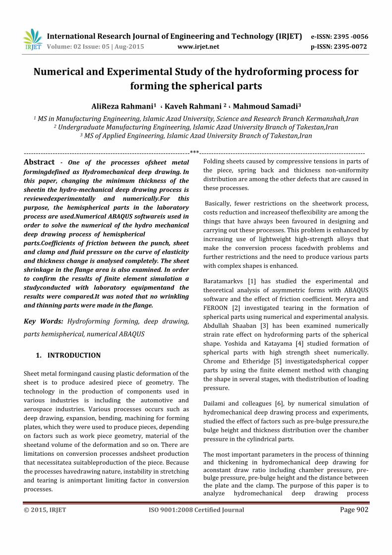
seconds. As can be seen in Figure 1, the pressure changes
in the process for forming and pre-bulge are linear.
Figure - 1: The chamber pressure changes during
the process
The material used is ST12 with the properties in Table 1.
Table-1: material properties and process parameters
size characteristics (unit)
Low-carbon
steel St-12
Material
1 Thickness (mm)
294 Yield strength (MPa)
401 The ultimate stress (MPa)
7.8 Density (g / cm3)
515 Coefficient of strength(MPa)
0.22 The strain hardening
0.3 Poisson's ratio
210 Modulus of elasticity (GPa)
60 Mandrel height (mm)
25 Radius mandrel (mm)
30×30 Matrix hole dimensions (mm × mm)
Mould, punch and plumb are modelled as rigid. The
definition of the friction surfaces in the process of deep
drawing is one of the most critical steps in the simulation
process. The thickness of the pieces has to be modelled
perfectly. Changing the Thickness has the most important
effect inhaving contact between the surface of the sheet
with the plumb andmatrix. Based on the experiments the
most ideal coefficient of friction was considered.
Coefficient of friction between the sheet and the plumb is
05 / 0 andbetween the punch and matrixis 1/0 and
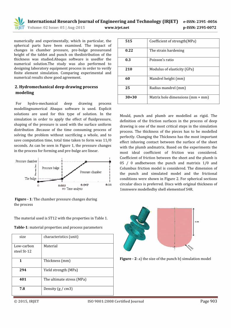
Columbus friction model is considered. The dimension of
the punch and simulated model and the frictional
conditions were shown in Figure 2. For spherical sections
circular discs is preferred. Discs with original thickness of
1mmwere modelledby shell elementsof S4R.
Figure - 2: a) the size of the punch b) simulation model
International Research Journal of Engineering and Technology (IRJET) e-ISSN: 2395 -0056
Volume: 02 Issue: 05 | Aug-2015 www.irjet.net p-ISSN: 2395-0072
© 2015, IRJET ISO 9001:2008 Certified Journal Page 904
Table-2: Coefficients of friction between the tablet
and tools
0/05 The coefficient of friction at the contact
surface between the sheet and plumb
0/1 The coefficient of friction at the contact
surface between the sheet and punch
0/05 The coefficient of friction at the contact
surface between the plate and mold
3. Drawing ratio
In The circular pieces,the ratio of sheet diameter to punch
diameterof draw ratio is defined as the ratio of elasticity.
4. The impact of the pressure chamber
The force of forming includes the primary pressure of
chamber and the ultimate pressure. The first step is
sheetbuilding;total degrees of freedom for punch, matrix
and plumbwere taken. In the first phase, the fluid pressure
gradually applied to the sheet to prevent the dynamic
effects. Fluid pressure increases linearly in bulging stage
in order toapply the primary pressure chamber. By
applying the pressure at the end of this stage, the top of
the sheet will be tangent to the punch.
In the second phase,degrees of freedom of punch were
moved to the matrix hole .punch moves to the matrix with
a maximum speed mm / s5. At this stage, with the moves
of punch into the chamber pressure gradually increased to
reach the pressure of relief valve setting. Various
scenarios have been considered for the fluid pressure
changes to determine the impact on the chamber pressure
on the maximum thinning and different simulations for
final chamber pressure Bar 500 and 450..... 100 and 50
were performed. In all phasespre-bulge pressure was
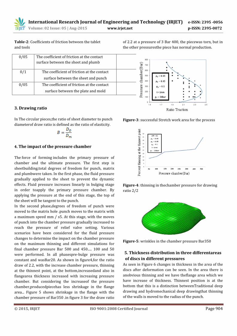
constant and wasBar20. As shown in figure4,for the ratio
draw of 2.2, with the increase chamber pressure, thinning
at the thinnest point, at the bottom,increasedand also in
flangearea thickness increased with increasing pressure
chamber. But considering the increaseof the pressure
chamber,producedpiecehas less shrinkage in the flange
area... Figure 5 shows shrinkage in the flange with the
chamber pressure of Bar350 .in figure 3 for the draw ratio
of 2.2 at a pressure of 3 Bar 400, the piecewas torn, but in
the other pressuresthe piece has normal production.
Figure-3: successful Stretch work area for the process
Figure-4: thinning in thechamber pressure for drawing
ratio 2/2
Figure-5: wrinkles in the chamber pressure Bar350
5. Thickness distribution in three differentareas
of discs in different pressures
As seen in Figure 6 changes in thickness in the area of the
discs after deformation can be seen. In the area there is
anobvious thinning and we have theflange area which we
have increase of thickness. Thinnest position is at the
bottom that this is a distinction betweenTraditional deep
drawing and hydromechanical deep drawingthat thinning
of the walls is moved to the radius of the punch.
International Research Journal of Engineering and Technology (IRJET) e-ISSN: 2395 -0056
Volume: 02 Issue: 05 | Aug-2015 www.irjet.net p-ISSN: 2395-0072
© 2015, IRJET ISO 9001:2008 Certified Journal Page 905
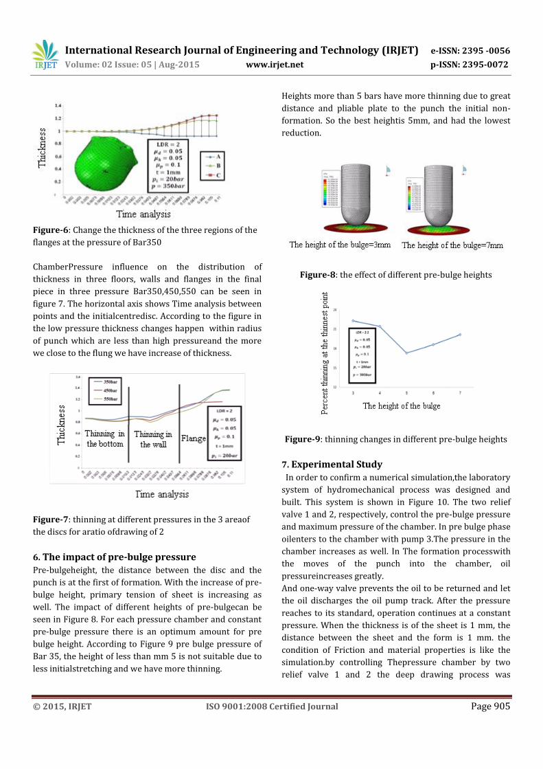
Figure-6: Change the thickness of the three regions of the
flanges at the pressure of Bar350
ChamberPressure influence on the distribution of
thickness in three floors, walls and flanges in the final
piece in three pressure Bar350,450,550 can be seen in
figure 7. The horizontal axis shows Time analysis between
points and the initialcentredisc. According to the figure in
the low pressure thickness changes happen within radius
of punch which are less than high pressureand the more
we close to the flung we have increase of thickness.
Figure-7: thinning at different pressures in the 3 areaof
the discs for aratio ofdrawing of 2
6. The impact of pre-bulge pressure
Pre-bulgeheight, the distance between the disc and the
punch is at the first of formation. With the increase of pre-
bulge height, primary tension of sheet is increasing as
well. The impact of different heights of pre-bulgecan be
seen in Figure 8. For each pressure chamber and constant
pre-bulge pressure there is an optimum amount for pre
bulge height. According to Figure 9 pre bulge pressure of
Bar 35, the height of less than mm 5 is not suitable due to
less initialstretching and we have more thinning.
Heights more than 5 bars have more thinning due to great
distance and pliable plate to the punch the initial non-
formation. So the best heightis 5mm, and had the lowest
reduction.
Figure-8: the effect of different pre-bulge heights
Figure-9: thinning changes in different pre-bulge heights
7. Experimental Study
In order to confirm a numerical simulation,the laboratory
system of hydromechanical process was designed and
built. This system is shown in Figure 10. The two relief
valve 1 and 2, respectively, control the pre-bulge pressure
and maximum pressure of the chamber. In pre bulge phase
oilenters to the chamber with pump 3.The pressure in the
chamber increases as well. In The formation processwith
the moves of the punch into the chamber, oil
pressureincreases greatly.
And one-way valve prevents the oil to be returned and let
the oil discharges the oil pump track. After the pressure
reaches to its standard, operation continues at a constant
pressure. When the thickness is of the sheet is 1 mm, the
distance between the sheet and the form is 1 mm. the
condition of Friction and material properties is like the
simulation.by controlling Thepressure chamber by two
relief valve 1 and 2 the deep drawing process was
International Research Journal of Engineering and Technology (IRJET) e-ISSN: 2395 -0056
Volume: 02 Issue: 05 | Aug-2015 www.irjet.net p-ISSN: 2395-0072
© 2015, IRJET ISO 9001:2008 Certified Journal Page 906
conducted under different drawing ratios and the
distribution of thickness and work area was designated.
Figure-10: experimental test system of HDD process
8. Comparing thinning and empiricalsimulation
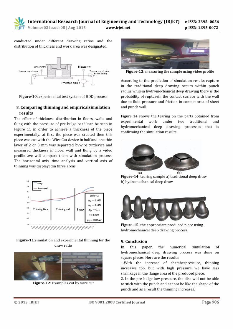
results The effect of thickness distribution in floors, walls and
flung with the pressure of pre-bulge bar20can be seen in
Figure 11 in order to achieve a thickness of the piece
experimentally, at first the piece was created then this
piece was cut with the Wire Cut device in half and one thin
layer of 2 or 3 mm was separated bywire cutdevice and
measured thickness in floor, wall and flung by a video
profile .we will compare them with simulation process.
The horizontal axis, time analysis and vertical axis of
thinning was displayedin three areas.
Figure-11:simulation and experimental thinning for the
draw ratio
Figure-12: Examples cut by wire cut
Figure-13: measuring the sample using video profile
According to the prediction of simulation results rupture
in the traditional deep drawing occurs within punch
radius whilein hydromechanical deep drawing there is the
probability of rupturein the contact surface with the wall
due to fluid pressure and friction in contact area of sheet
and punch wall.
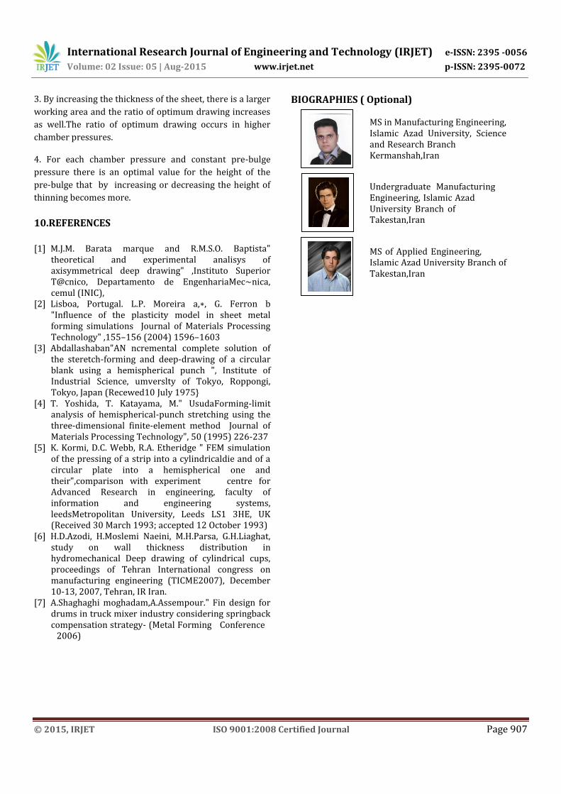
Figure 14 shows the tearing on the parts obtained from
experimental work under two traditional and
hydromechanical deep drawing processes that is
confirming the simulation results.
Figure-14: tearing sample a) traditional deep draw
b) hydromechanical deep draw
Figure-15: the appropriate produced piece using
hydromechanical deep drawing process
9. Conclusion
In this paper, the numerical simulation of
hydromechanical deep drawing process was done on
square pieces. Here are the results:
1.With the increase of chamberpressure, thinning
increases too, but with high pressure we have less
shrinkage in the flange area of the produced piece.
2. In the pre-bulge low pressure, the disc will not be able
to stick with the punch and cannot be like the shape of the
punch and as a result the thinning increases.
International Research Journal of Engineering and Technology (IRJET) e-ISSN: 2395 -0056
Volume: 02 Issue: 05 | Aug-2015 www.irjet.net p-ISSN: 2395-0072
© 2015, IRJET ISO 9001:2008 Certified Journal Page 907
3. By increasing the thickness of the sheet, there is a larger
working area and the ratio of optimum drawing increases
as well.The ratio of optimum drawing occurs in higher
chamber pressures.
4. For each chamber pressure and constant pre-bulge
pressure there is an optimal value for the height of the
pre-bulge that by increasing or decreasing the height of
thinning becomes more.
10.REFERENCES
[1] M.J.M. Barata marque and R.M.S.O. Baptista" theoretical and experimental analisys of axisymmetrical deep drawing" ,Instituto Superior T@cnico, Departamento de EngenhariaMec~nica, cemul (INIC),
[2] Lisboa, Portugal. L.P. Moreira a,∗, G. Ferron b "Influence of the plasticity model in sheet metal forming simulations Journal of Materials Processing Technology" ,155–156 (2004) 1596–1603
[3] Abdallashaban"AN ncremental complete solution of the steretch-forming and deep-drawing of a circular blank using a hemispherical punch ", Institute of Industrial Science, umverslty of Tokyo, Roppongi, Tokyo, Japan (Recewed10 July 1975}
[4] T. Yoshida, T. Katayama, M." UsudaForming-limit analysis of hemispherical-punch stretching using the three-dimensional finite-element method Journal of Materials Processing Technology", 50 (1995) 226-237
[5] K. Kormi, D.C. Webb, R.A. Etheridge " FEM simulation of the pressing of a strip into a cylindricaldie and of a circular plate into a hemispherical one and their",comparison with experiment centre for Advanced Research in engineering, faculty of information and engineering systems, leedsMetropolitan University, Leeds LS1 3HE, UK (Received 30 March 1993; accepted 12 October 1993)
[6] H.D.Azodi, H.Moslemi Naeini, M.H.Parsa, G.H.Liaghat, study on wall thickness distribution in hydromechanical Deep drawing of cylindrical cups, proceedings of Tehran International congress on manufacturing engineering (TICME2007), December 10-13, 2007, Tehran, IR Iran.
[7] A.Shaghaghi moghadam,A.Assempour." Fin design for drums in truck mixer industry considering springback compensation strategy- (Metal Forming Conference 2006)
BIOGRAPHIES ( Optional)
MS in Manufacturing Engineering, Islamic Azad University, Science and Research Branch Kermanshah,Iran
Undergraduate Manufacturing Engineering, Islamic Azad University Branch of Takestan,Iran
MS of Applied Engineering, Islamic Azad University Branch of Takestan,Iran